

Page 1
SiS964/Silicon 3112A SATA
RAID User’s Manual
User’s Guide
Page 2

Serial ATA RAID User’s Guide
Edition
V1.0
P/N:
91-185-755-10-00
Trademarks
All brand or product names mentioned are trademarks or registered
trademarks of their respective holders.
Page 3

Serial ATA RAID User’s Guide
CONTENTS
Introduction ................................................................................................1
Features.......................................................................................................2
Support operating Systems........................................................................2
KNOW HOW..........................................................................................3
PERFORMANCE HINTS AND RECOMMEND SETTING.............3
Step 1. Hardware Setup .............................................................................4
HARD DRIVES SETUP ........................................................................4
FOR RAID 0 (STRIPING ARRAY) ...............................................................4
FOR RAID 1 (MIRROR ARRAY).................................................................. 4
FOR JBOD (SPANNING ARRAY)................................................................4
Step 2. Installing Software Drivers ...........................................................5
WINDOWS XP/2000..............................................................................5
NEW WINDOWS XP/2000 INSTALLATION ................................................ 5
EXISTING WINDOWS XP/2000 INSTALLATION.......................................6
CONFIRMING WINDOWS XP/2000 DRIVER INSTALLATION................6
Step 3. BIOS Utility Operation..................................................................7
STARTING BIOS UTILITY.................................................................7
CREATE RAID ....................................................................................10
CREATING A RAID 0 (STRIPE) ARRAY FOR PERFORMANCE............ 10
CREATING A RAID 1 (MIRROR) ARRAY.................................................14
CREATING A JBOD ARRAY ...................................................................... 18
DELETE RAID.....................................................................................22
STARTING TO DELETE A RAID ARRAY................................................. 22
Step 4. SiS964 RAID Utility.....................................................................25
STARTING TO USE SIS964 RAID UTILITY..................................25
Page 4

Serial ATA RAID User’s Guide
ABOUT CREATE RAID....................................................................28
VIEWING THE “CREATE RAID” ...............................................................28
CREATE A RAID SET.................................................................................. 30
ABOUT DELETE RAID.....................................................................38
VIEWING THE RAIDTYPE MEANING......................................................38
DELETE A RAID SET ..................................................................................39
ABOUT RAID RECOVERY..............................................................41
RAID RECOVERY OPERATION................................................................. 41
SATA RAID Software to be used with the SiI 3112..............................43
Page 5

Serial ATA RAID User’s Guide
Introduction
The South Bridge SiS964 SATA controller support two Serial ATA on two
independent ports. Specifications are as follows:
Serial ATA Interface
Serial ATA (SATA) is the latest generation of the ATA interface. SAT A hard
drives deliver blistering transfer speeds of up to 150MB/sec. Serial ATA uses
long, thin cables, making it easier to connect your drive and improving the
airflow inside your PC.
♦ Supports 150 MB/s transfers with CRC error checking
♦ Large LBA support for drives over 137 GB
♦ Data handling optimizations including tagged command queuing, elevator seek
and packet chain command
Serial ATA RAID Interfaces
The Serial ATA RAID is designed to provide a cost-effective, high
performance RAID solution that adds performance and/or reliability to PC
desktops and/or servers using Serial ATA/150 hard disks.
Serial ATA RAID function supports striping (RAID 0), mirroring (RAID 1) and
span (JBOD).
With striping, identical drives can read and write data in parallel to increase
performance. Mirroring increases read performance through load balancing
and elevator sorting while creating a complete backup of your files. Span
would increase the logic hard disk space.
Serial ATA RAID striped arrays can double the sustained data transfer rate
of Serial ATA/150 drives. Serial ATA RAID fully supports Serial ATA/150
specification of up to 150MB/sec per drive, depending on individual drive
specifications.
The technology also offers fault tolerant, data redundancy for entry-level
network file servers or simply for desktop PC users wanting to continually
protect valuable data on their PC. The Serial ATA RAID offers RAID 1
mirroring (for two SATA drives) to protect data. Should a drive that is part of
a mirrored array fail, Serial ATA RAID technology uses the mirrored drive
(which contains identical data) to assume all data handling. When a new
replacement drive is later installed, Serial ATA RAID rebuilds data to the new
drive from the mirrored drive to restore fault tolerance.
1
Page 6

Serial ATA RAID User’s Guide
Features
The South Bridge SiS964 SATA controller only support two Serial ATA
(Serial ATA RAID) drivers.
Support RAID function: RAID 0, RAID 1 and JBOD.
Support bootable disk.
Windows-based SiS RAID Utility software tool (only support Windows
XP and 2000).
BIOS RAID Setting Utility.
Support operating Systems
Microsoft Windows 2000 Professional and Server
Microsoft Windows XP
2
Page 7

Serial ATA RAID User’s Guide
Step 0. What is RAID
Know How
This section will give you an overview about the RAID system and introduce
the basic background and glossary which you need to know before using
“SiS RAID Controller Application”.
1. RAID: (Redundant Array of Independent Disk Drives) use jointly several
hard drives to increase data transfer rates and data security. It depends
on the number of drives present and RAID function you select to fulfill
the security or performance purposes or both.
2. RAID 0: Also known as “Stripping”. All of the data are distributed evenly
to all of the existing drives. You gain benefits on performance because
the data transfer rate is multiplied by the number of drives. However,
RAID 0 has high risks of data security. All of the stored data will be lost if
even any one drive in the RAID set crashes.
3. RAID 1: Also known as “Mirroring”. Two hard drives are required. The
goal of RAID 1 is to ensure data security. Data is written to two or more
drives synchronously. That is, 100% duplication of data from one drive
to another.
4. JBOD: (Just a Bunch of Drives). Also known as “Spanning”. Two or
more hard drives are required. Several hard disk types configured as a
single hard disk. The hard drives are simply hooked up in series. This
expands the capacity of your drive and results in a useable total capacity.
However, JBOD will not increase any performance or data security.
Performance hints and recommend setting
For the best performance and reliability, please read the following
suggestions.
1. Use the same model hard drives.
2. If you have only two Serial ATA drives, the auto-configure function will
assign each on a different channel as a master drive.
3. Always use 80-conductor cables.
4. We strongly recommend you should use “DMA” transfer mode.
5. The recommended block size is “64K” when creating RAID 0.
3
Page 8

Serial ATA RAID User’s Guide
Step 1. Hardware Setup
Hard Drives setup
The South Bridge SiS964 SATA controller only supports two Serial ATA
hard drivers.
For RAID 0 (Striping array)
Any of 2 SATA Hard disks would make a stripe system.
The South Bridge SiS964 SATA controller only supports combination 6.
NOTE: Storage Capacity: the number of hard drives times the capacity of the
smallest drive in the disk array
Working Speed: the speed of the lowest drive in the disk array
For RAID 1 (Mirror array)
Any of 2 SATA Hard disks would make a mirror system.
The South Bridge SiS964 SATA controller only supports combination 6.
NOTE: Storage Capacity: the capacity of the smallest drive in the disk array
Working Speed: the speed of the lowest drive in the disk array
For JBOD (Spanning array)
Any of 2 SATA Hard disks would combine to a JBOD system.
The South Bridge SiS964 SATA controller only supports combination 6.
NOTE: Storage Capacity: the number of hard drives times the capacity of the
smallest drive in the disk array
Working Speed: the speed of the lowest drive in the disk array
4
Page 9

Serial ATA RAID User’s Guide
NOTE: Before Installing software drivers, make sure to set the item
“SIS Serial ATA Mode” to Raid in “Integrated Peripherals”
of BIOS Setup.
Step 2. Installing Software Drivers
SiS RAID driver support Microsoft Windows XP/2000
1. South Bridge SiS964 SATA controller support Serial ATA W/ RAID0,
RAID 1 and JBOD by installing SiS RAID driver. For RAID function, SIS
964 support RAID0, RAID1 and JBOD by software RAID driver.
2. Support the function of installing Windows Operation System to
RAID array.
For special occasions, users can refer to the following sections with
details on the SiS964 driver installation when used with Windows
XP/2000 operating systems.
Windows XP/2000
New Windows XP/2000 Installation
The following details the installation of the drivers while installing new
Windows XP/2000.
1. Start the installation:
Boot from the CD-ROM. Press F6 when the message “Press F6
key if you need to install third party SCSI or RAID driver” appears.
2. When the Windows XP/2000 Setup window is generated, press S
key to specify an Additional Device(s).
3. Insert the driver diskette into drive A: and press Enter.
4. Choose one of the following items:
“WinXP SiS Raid/IDE Controller ”,
“Win2000 SiS Raid/IDE Controller”,
5
Page 10

Serial ATA RAID User’s Guide
that appears on screen, and then press the Enter key.
5. Press Enter to continue with installation or if you need to specify
any additional devices to be installed, do so at this time. Once all
devices are specified, Press Enter to continue with installation.
6. From the Windows XP/2000 Setup screen, press the Enter key.
Setup will now load all device files and then continue the
Windows XP/2000 installation.
7. Please install the driver package again (ex. SiS RAID driver
v1.03) while the operation system has been setup.
Remark:
If you would like to install windows to any RAID sets, you should
create RAID from BIOS RAID setting Utility or SiS964 RAID Utility
first and then follow the steps above. Pleaser refer to step 3 or step
4.
Existing Windows XP/2000 Installation
1. Install the driver by execute SiS RAID driver setup utility.
2. The drivers will be automatically installed.
Confirming Windows XP/2000 Driver Installation
1. From Windows XP/2000, open the Control Panel from “My
Computer” followed by the System icon.
2. Choose the “Hardware” tab, then click the “Device Manager” tab.
3. Click the “+” in front of “SCSI and RAID Controllers” hardware type.
The driver “ SiS 180 Raid Controller ” should appear.
6
Page 11
Serial ATA RAID User’s Guide
Step 3. BIOS Utility Operation
Note:
For the best performance and reliability, please read “Performance Hints
and Recommend Setting” section in Step 0.
Starting BIOS Utility
1. Boot your system. If this is the first time you have booted with the
SiS964 and the drives installed, the BIOS will display the following.
Silicon Integrated Systems Corp. RAID BIOS Setting Utility v0.XX
(c) 2003-2005 Silicon Integrated Systems Corp. All Rights Reserved.
Press <Ctrl><S> to run BIOS Setting Utility
Scan Devices. Please wait…………
Primary Master : XXXXXXXXXX XXXXXMB UDMA X
Secondary Master : < SATA Device Not Found >
[ RAID Information ]
[ RAID Information ] includes some statements. See below :
a. No RAID Install !! Not any completed RAID exists.
b. Raid 1 (Mirror) : [Disk X] [Disk X] Have a RAID set.
c. Broken RAID detected. Do you want to enter Setup Menu (Y/N)?
Y
You can select [Y] to enter setup menu to handle it. Or you can select
[N] to ignore this message.
d. Found a new HD! Do you want to rebuild RAID 1?
Y Occurs when
the controller has broken Raid 1 and single HDD existing simultaneously
and the location of single HDD is just conformed it’s rebuild conditions.
e. The Raid is wrong!! Do you want to fix it??(Y/N) Occurs when the
locations of two SATA HDD change owing to ATA HDD existing or not.
7
Page 12
Serial ATA RAID User’s Guide
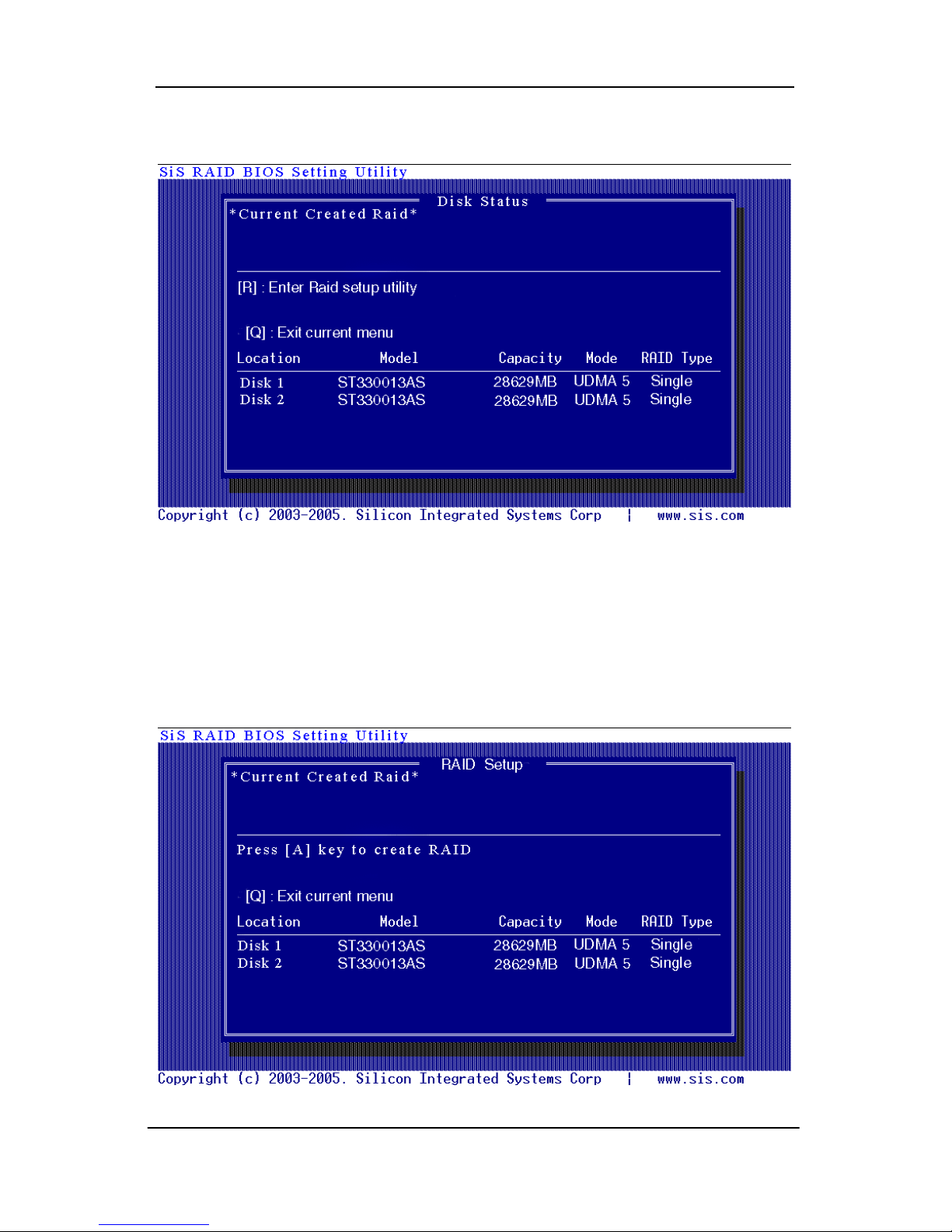
2. Press <Ctrl-S> keys to display the SiS964 Utility Main Menu.
3. Press <R> to display the RAID setup menu below. This is the fastest
and easiest method to create your first array. The [A] and [D] key will
appear randomly in the different conditions.
[a]. No RAID existing but have available disks existing :
8
Page 13
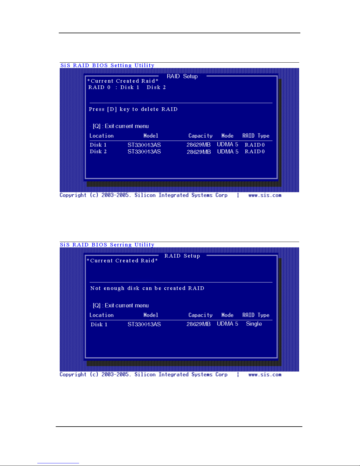
Serial ATA RAID User’s Guide
[b]. No available disk existing but have RAID existing:
[c]. Available disk is not enough to create RAID:
9
Page 14
Serial ATA RAID User’s Guide
Create RAID
Creating a RAID 0 (Stripe) Array for Performance
NOTE:
SiS964 only supports 2 SATA drivers to create a stripe array.
To create an array for best performance, follow these steps:
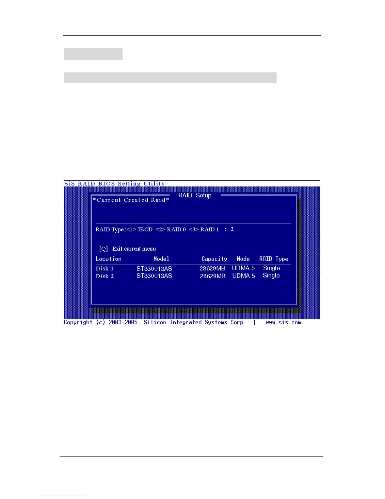
1. Press <A> to start creating a RAID array.
2. Press <2> and <Enter> to select RAID 0.
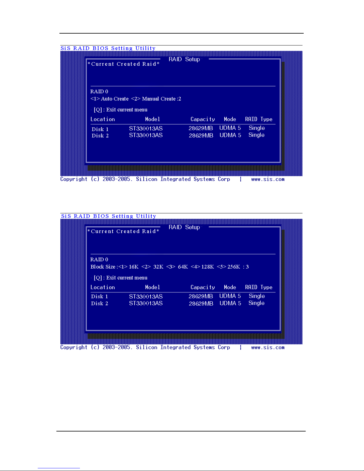
3. You will have two selections to create a RAID 0 array. The default
value is <1>. If you select <1>Auto Create, you can create a RAID 0
array faster and easier. The Blocksize will be selected by its default
value “64K”. The result after auto creating will be shown on step 6.
Besides, you also can select <2>Manual Create, see following steps.
10
Page 15
Serial ATA RAID User’s Guide
4. Press <1>─<5> keys and <Enter> to select Block Size. ( Default : 64K )
5. Use <↑> <↓> to select disk , and press <Enter> to select disk, <Q> to
exit. When you press <Enter> on the disk you wanted, the RAID Type
will be changed from Single to RAID 0. And the disk you select first will
be the SOURCE disk.
11
Page 16

Serial ATA RAID User’s Guide
6. Next, you will see a message “Split the SOURCE(Disk x) data to RAID
disks?”. Press <N> and <Enter> to create RAID 0 array only or press
<Y> and <Enter> to split the data from source disk to other disks.
12
Page 17
Serial ATA RAID User’s Guide
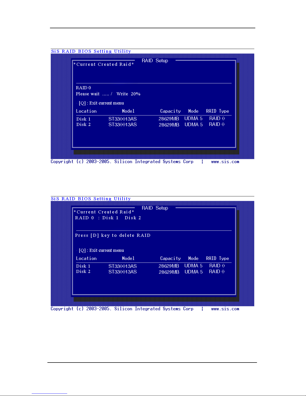
7. Starting splitting action, the following frame will be shown.
8. After all steps finished, press <Q> until escape the setup menu and
RAID 0 array will be shown on the top of the main frame.
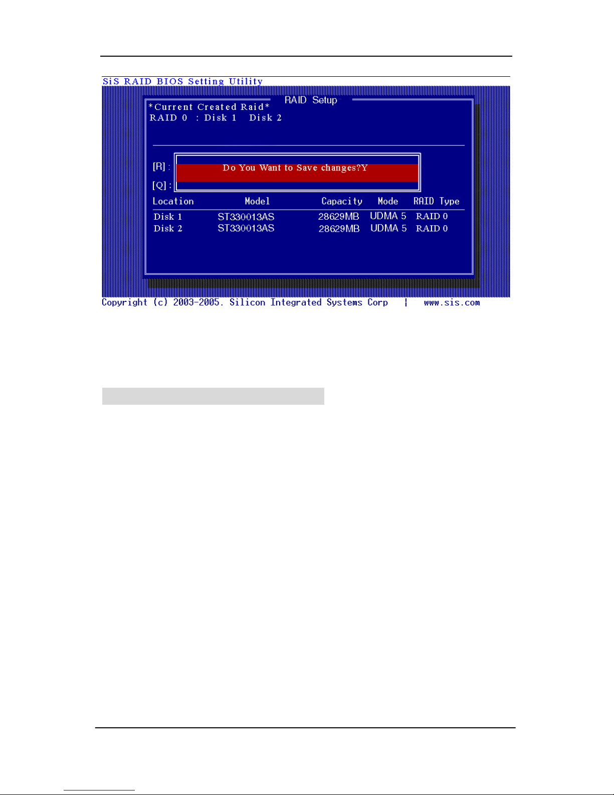
9. Press <Q> until exit this BIOS utility and the red message frame will
show. Press <Y> and <Enter> to save changes.
13
Page 18
Serial ATA RAID User’s Guide
10. Once the array has been created, you will need to FDISK and FORMAT
the array as if it was a new single hard drive.
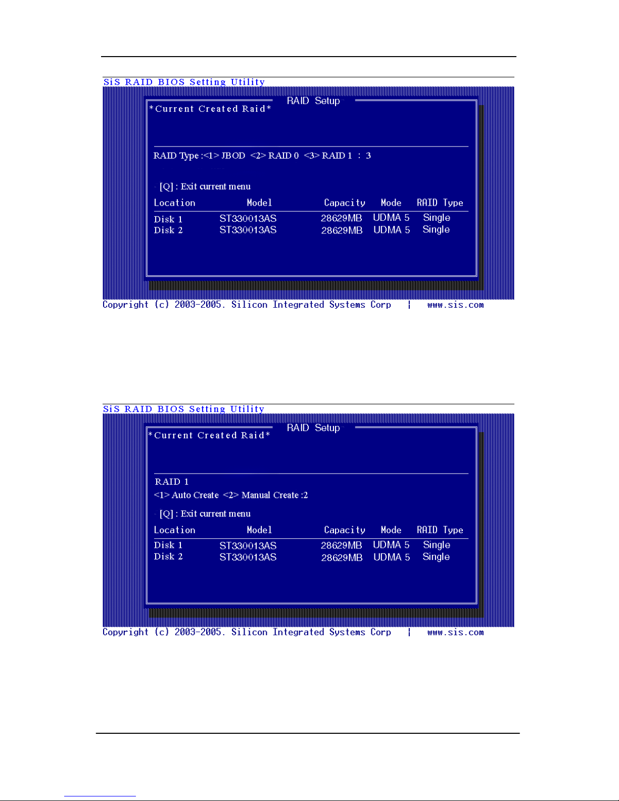
Creating a RAID 1 (Mirror) Array
NOTE:
SiS964 enables users to create Mirror arrays with pair of drives only.
To create a Mirror array, follow these steps:
1. Press <A> to start creating a RAID array.
2. Press <3> and <Enter> to select Mirror.
14
Page 19
Serial ATA RAID User’s Guide
3. You will have two selections to create a RAID 1 array. The default
value is <1>. If you select <1>Auto Create, you can create a RAID 1
array faster and easier. The result after creating will be shown on step 5.
Besides, you also can select <2>Manual Create, see following steps.
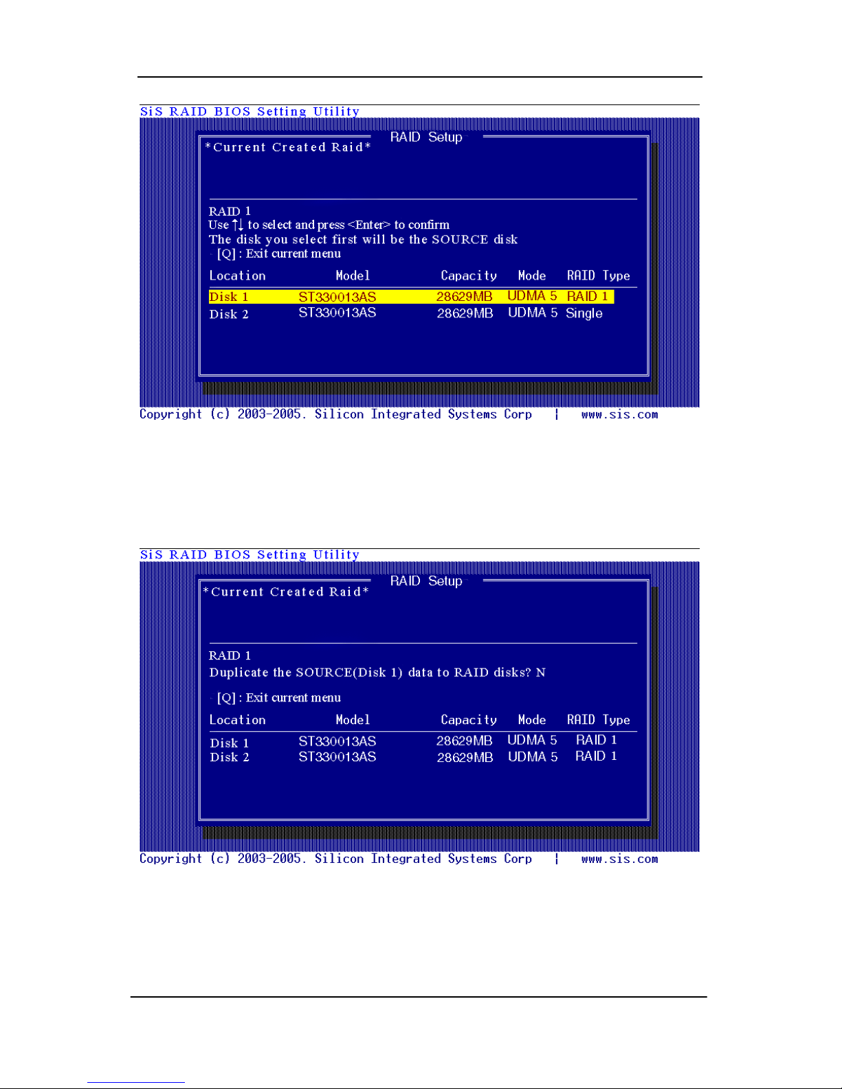
4. Use <↑> <↓> to select disk , and press <Enter> to select disk, <Q> to
exit. When you press <Enter> on the disk you wanted, the RAID Type
will be changed from Single to RAID 1. The same as RAID 0, the disk
you select first will be the SOURCE disk.
15
Page 20
Serial ATA RAID User’s Guide
5. Next, you will see a message “Duplicate the SOURCE(Disk x) data to
RAID disks?”. Press <N> and <Enter> to create RAID 1 array only or
press <Y> and <Enter> to duplicate the data from source disk to mirror
disk.
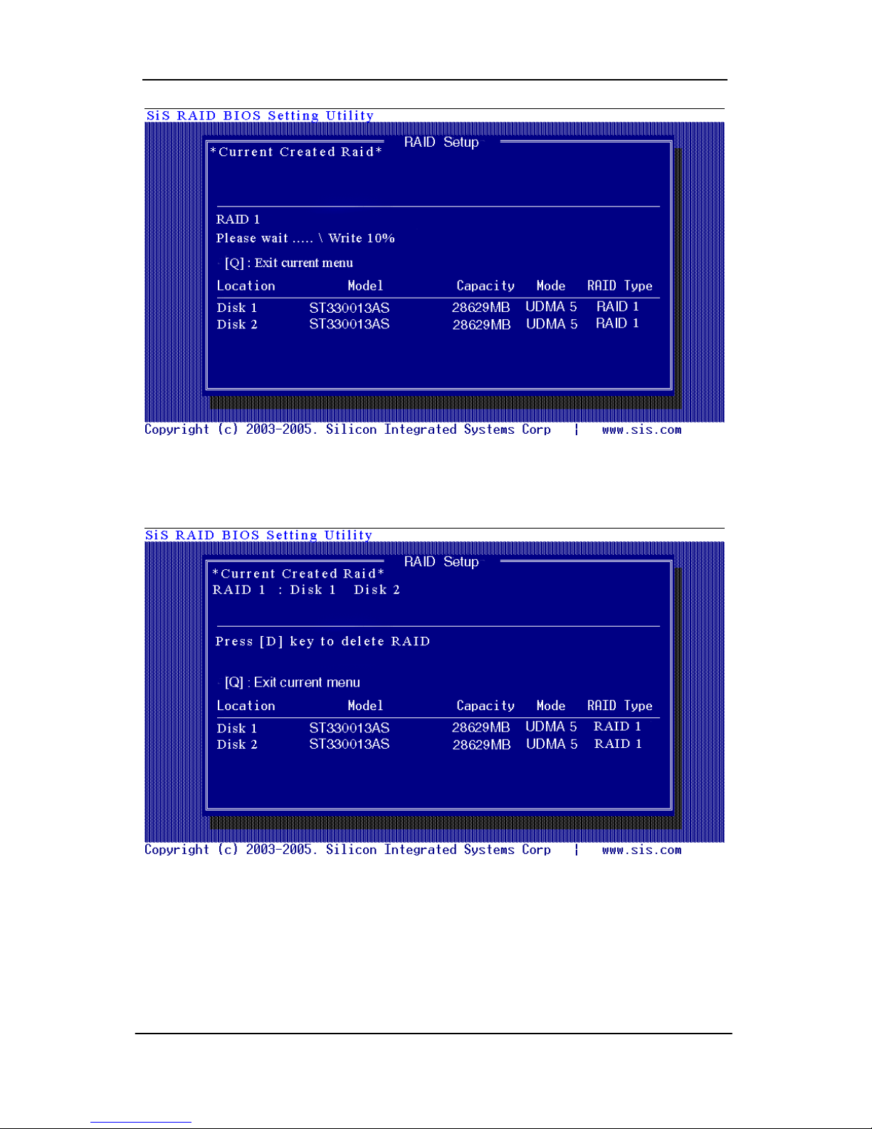
6. Starting duplicating action, the following frame will be showing.
16
Page 21
Serial ATA RAID User’s Guide
7. After all steps finished, press <Q> until escape the setup menu and
RAID 1 array will be shown on the top of the main frame.
8. Press <Q> until exit this BIOS utility and the red message frame will
show as the same as the creation of the RAID 0 array. Press <Y> and
<Enter> to save changes.
17
Page 22

Serial ATA RAID User’s Guide
9. Once the array has been created, you will need to FDISK and FORMAT
the array as if it were a new single hard drive.
Creating a JBOD Array
NOTE:
SiS964 only supports 2 SATA drivers to create a JBOD array.
To create a JBOD array, follow these steps:
1. Press <A> to start creating a RAID array.
2. Press <1> and <Enter> to select JBOD.
18
Page 23

Serial ATA RAID User’s Guide
3. You will have two selections to create a JBOD array. The default value
is <1>. If you select <1>Auto Create, you can create a JBOD array
faster and easier. The result after creating will be shown on step 5.
Besides, you also can select <2>Manual Create, see following steps.
4. Use<↑> <↓> to select disk , and press <Enter> to select disk, <Q> to
exit. When you press <Enter> on the disk you wanted, the RAID Type
will be changed from Single to JBOD.
19
Page 24

Serial ATA RAID User’s Guide
5. After all steps finished, press <Q> until escape the setup menu and
JBOD array will be shown on the top of the main frame.
6. Press <Q> until exit this BIOS utility and the red message frame will
show as the same as the creation of the RAID 0 array. Press <Y> and
<Enter> to save changes.
20
Page 25

Serial ATA RAID User’s Guide
7. Once the array has been created, you will need to FDISK and FORMAT
the array as if it were a new single hard drive.
21
Page 26

Serial ATA RAID User’s Guide
Delete RAID
Starting to delete a RAID array
1. After enter the SiS964 Utility Main Menu, press <R> to display the
RAID setup menu below. This is the fastest and easiest method to delete
your first array.
2. Press <D> to start deleting a RAID array.
22
Page 27

Serial ATA RAID User’s Guide
3. Press <Enter> to select the RAID array that you want to delete. And a
message “Are you sure to delete this RAID?” will show on this frame.
4. Press <Y> and <Enter>, the deleting action finish. And the RAID Type of
all disk members of this RAID array will be changed from RAID 0 to
Single.
23
Page 28

Serial ATA RAID User’s Guide
5. Press <Q> until escape the BIOS Utility, and the red message frame will
show on it.
6. Press <Y> and <Enter> to save all changes.
24
Page 29

Serial ATA RAID User’s Guide
Step 4. SiS964 RAID Utility
Note:
1.
For the best performance and reliability, please read “Performance
Hints and Recommend Setting” section in Step 0.
2. T his Utility only supports Windows XP/2000.
Starting to use SiS964 RAID Utility
1) After installing the SiS RAID utility, go to “Start” menu and choose
“Programs.” From the “Programs” menu, choose “SiS RAID” and click on
“SiSRaid”.
The detail process of installing the SiS RAID utility, please refer 755
series user manual page 60
25
Page 30

Serial ATA RAID User’s Guide
2) This SiS RAID utility will be resident in the toolbar. You can click the right
button of the mouse on the SiS Raid Utility’s icon and some selection will
be popup. You can click “Exit” to close this resident utility or let it always
be resident in the toolbar. Or click “SiS Raid” to open the SiS RAID Utility
as Step (3). The “Help” will show the help document to tell you how to
use this RAID Utility and the “About” will show as Step (5).
3) The SiS RAID Utility window opens as below. The main interface has two
tabs: View and Configuration. You can switch to different tabs by clicking
on it. On “View” tab, we can see some device information on different
controllers. You can click the drop-down box “Adapter” to select the
controller you want to use. The default value is the information of the first
device on “SiS RAID controller 1”.
26
Page 31

Serial ATA RAID User’s Guide
Besides, if this controller has some broken RAID existing, this AP will
show some warning message on initial time. If this broken RAID is RAID 1,
it will tell you that you can go to the “Raid Recovery” tab to recovery this
broken RAID 1.
3) Click the button “Help”, you can open a help document that tell you how
to use this RAID utility.
4) Click the button “About”, you can find an about message. It show that
RAID utility version ( version 0.XX ) and some copyright information.
5) Click the tab “configuration”, you can find three tabs: Create Raid, Delete
Raid and Raid Recovery. In the same way, you can switch to different
tabs by clicking on it.
27
Page 32

Serial ATA RAID User’s Guide
About Create Raid
Click the tab “Create Raid”, you can find three drop-down boxs and three
panes. Those meaning will be showing below.
Viewing the “Create Raid”
a) Raid Type: Click the drop-down box “Raid Type”. This box enables the
user to select array type. There are four array types that the user can
select: JBOD, RAID 0 (Stripe) and RAID 1 (Mirror). User can select any
one array type to create a RAID set.
b) Block Size: If user selected RAID 0 array type in the “Array Type” box,
the “Block Size” drop-down box will be enabled and user must select a
block size. Clicking the drop-down box “Block Size”, there are seven
block sizes that the user can select: 8k, 16k, 32k, 64K, 128K, 256K and
512K. User can select any one block size to create a RAID 0 set. The
default selection is 64K.
28
Page 33

Serial ATA RAID User’s Guide
c) Mode Type: Click the drop-down box “Mode Type”. This box enables
the user to select mode type. There are two mode types that the user
can select: PIO and DMA. User can select any one mode type to
create a RAID set. The default selection is DMA.
d) Available Disks: This pane will list out all the disks that can be used to
create a RAID set currently. It will show some disk information.
29
Page 34

Serial ATA RAID User’s Guide
e) Selected Disks: This pane will list out all the disks that have been
selected to create a RAID set. User can highlight the specific disk that
we want in the “Available Disks” pane and click the downward arrow
icon or double click the marked disk to select the disk into the
“Selected Disks” pane. In the same way, user can click the upward
arrow icon or double click the marked disk in the “Selected Disks” to
get back the disk that we might select wrong to the “Available Disks”
pane.
f) Information: This pane will show the information about creating a
RAID set after clicking the button “Create”. The information may be
“Please select the <Raid Type> first!”, "Please select the <Mode Type>
first!", "Please select the <Block Size> first!", "Please select the disk
you want first!", "Mirror supports TWO DISKS only.", "Raid Created
successful! Reboot please!!" or "Raid Creation failed!".
Create a RAID set
a) To create a JBOD array, follow these steps:
NOTE: You should use two SATA hard disks to create a JBOD array.
1. “Configuration” → “Create Raid” → “Raid Type” → JBOD.
2. From the drop-down box “Mode Type”, select the mode type you want
or use the default value “DMA”.
3. From the “Available Disks” pane, select the disk and click downward
arrow icon or double click it to add the disk on the “Selected Disks”
pane.
30
Page 35

Serial ATA RAID User’s Guide
4. When the JBOD array’s configuration is finished, click the button
“Create”. Then a warning message will be popup. Pay attention to the
warning message, and then click “Yes” button to finish the creation of
JBOD array, or click “No” button to cancel.
NOTE: If the disk you selected has the ability of booting, another
warning message will be popup before “SiS Software RAID”
message. You can click “Yes” button to continue or click “No”
button to cancel.
31
Page 36

Serial ATA RAID User’s Guide
5. Next, another message box will be popup to tell user that disk setting
has been changed and ask whether to restart the computer or not.
Click “Yes” button to restart the computer and you can get new setting.
Or click “Cancel” button to skip restarting.
b) To create a RAID 0 (Stripe) array, follow these steps:
NOTE: You should use two SATA hard disks to create a RAID0 array.
1. “Configuration” → “Create Raid” → “Raid Type” → RAID 0.
2. From the drop-down box “Block Size”, select the block size you want
or use the default value “64K”.
3. From the drop-down box “Mode Type”, select the mode type you want
or use the default value “DMA”.
32
Page 37

Serial ATA RAID User’s Guide
4. From the “Available Disks” pane, select the disk and click downward
arrow icon or double click it to add the disk on the “Selected Disks”
pane. This action is the same as the operation to create a JBOD array.
5. When the RAID0 array’s configuration is finished, click the button
“Create”. Then a “Create Stripe RaidSet” dialog will be popup.
<Note>
Source : The first selected disk.
Target : All other disks but first one.
Create Only : This operation will destroy all data on all the selected
disks and create a clean stripe array without any data
on it.
<Split data into Raid0 Set>
Source is NOT a boot device: Split operation will split data from
source disk into all the selected
disks. In this operation, the source
disk can’t be a boot device.
Source is a boot device: This operation is similar to “Source is NOT
a boot device” operation, but the source
disk is a boot device.
33
Page 38

Serial ATA RAID User’s Guide
OK: Start the selected operation.
<Disk Copy Remaining Sector>: Show the remaining splitting data
sector numbers.
NOTE: miniCapacity x N > SourceCapacity
miniCapacity: The minimum size of all selected disks.
SourceCapacity: The size of source disk.
N: Total disk numbers.
6. Next, you can click “OK” button to continue after the operation being
selected. The differential warning messages will be popup following
the differential operations. If the operation is “Create Only”, the
warning messages are similar to JBOD array creation.
7. If the operation is “Source is NOT a boot device” of <Split data
into Raid0 Set>, the following warning message will be popup, seeing
below:
Next, you can click “Yes” button to start the operation or click “No” button
to cancel. When you click “Yes” button to start this operation, the following
warning message will be popup.
34
Page 39

Serial ATA RAID User’s Guide
Next, you can click “Yes” button to start the operation or click “No” button
to cancel. When you click “Yes” button to start this operation, the
operation will begin.
When this operation is beginning, you still can click the destroy button on
the “Create Stripe RaidSet” dialog to stop this operation. But this action
will cause the data of the source disk broken. And the following
message will be popup to remind you.
8. If the operation is “Source is a boot device” of <Split data into
Raid0 Set>, the following warning message will be popup, seeing
below:
Next, you can click “Yes” button to start the operation or click “No” button
to cancel. When you click “Yes” button to start this operation, the following
warning message will be popup.
35
Page 40

Serial ATA RAID User’s Guide
Next, you can click “Yes” button to start the operation or click “No” button
to cancel. When you click “Yes” button to start this operation, the following
warning message will be popup.
Next, you can click “Ok” button to restart the windows and start the
operation “Source is a boot device” of <Split data into Raid0 Set>. Or
click “Cancel” button to suspend this operation. But, this operation is still
done after restarting the windows next time.
c) To create a RAID 1 (Mirror) array, follow these steps:
NOTE: You should use two SATA hard disks to create a RAID1 array.
1. “Configuration” → “Create Raid” → “Raid Type” → RAID 1.
2. From the drop-down box “Mode Type”, select the mode type you want
or use the default value “DMA”.
3. From the “Available Disks” pane, select the disk and click downward
arrow icon or double click it to add the disk on the “Selected Disks”
pane. This action is the same as the operation to create a JBOD array.
4. When the RAID1 array’s configuration is finished, click the button
“Create”. Then a “Create Mirror RaidSet” dialog will be popup.
36
Page 41

Serial ATA RAID User’s Guide
<Note>
Source: The first selected disk.
Target: The second selected disk.
Create Only: This operation will destroy all data on all the selected
disks and create a clean mirror array without any data
on it.
Create and Duplicate: Duplicate operation will reserve data on the
source disk and copy them onto the target
disk.
OK: Start the operation.
Cancel: Cancel the operation.
<Disk Copy Remaining Sector>: Show the remaining copying data.
5. Next, you can click “Cancel” button to leave or click “OK” button to
continue after the operation being selected. The warning messages
will be popup following the differential operations. If the operation is
“Create Only”, the warning messages are similar to JBOD array
creation.
6. If the operation is “Create and Duplicate”, the following warning
message will be popup, seeing below:
37
Page 42

Serial ATA RAID User’s Guide
Next, you can click “Yes” button to start the operation or click “No”
button to cancel. When you click “Yes” button to start this operation, the
following warning message will be popup.
Click “OK” button to start this duplicating action. Don’t restart your
computer or it will cause the action fail.
7. When the operation is finished, the restart warning message will be
popup as well as JBOD array creation.
About Delete Raid
Click the tab “Delete Raid”, you can find some panes and two
buttons. The RaidType meaning will show below.
Viewing the RaidType meaning
General case: RAID0 (A = B C | D E)
<Meaning>
RAID0: Raid Type
38
Page 43

Serial ATA RAID User’s Guide
A: total number of disks in this Raid
B,C: the serial number of each disk in this Raid
D,E: a) Raid is correct, B=D C=E
b) Raid is error, D or E will show “?” or “!”.
In which, the meaning of “?” and “!” will show below.
Delete a Raid set
a) To delete a JBOD, RAID0 or RAID1 array, follow these steps:
1. “Configuration” → “Delete Raid”, the following windows will appear:
39
Page 44

Serial ATA RAID User’s Guide
2. Highlight the disk array in the “Current RaidType” pane, and then click
the “Information” button or double click the array. You can get some
information about the disk array.
3. If you want to delete a disk array you selected, you can highlight the
disk array and then click the button “Delete”. Then a warning message
will be popup, and pay attention to the warning message. You can click
“Yes” to delete the selected disk array or click “No” to cancel.
4. Next, another message will be popup to tell user the setting of these
disks have been changed and ask whether to restart the computer.
40
Page 45

Serial ATA RAID User’s Guide
About Raid Recovery
Click the tab “Raid Recovery”, you can find two panes and some buttons.
Those meaning will be showed below.
Raid Recovery Operation
NOTE: The recovering operation is workable only when error RAID1 set
exist.
a) First, you can click the button “Available Raid” to find whether any error
Raid set existing. See below:
Next, highlight the error Raid set you want to recovery. And you can
click the button “OK” to continue or click “Cancel” to cancel this operation.
41
Page 46

Serial ATA RAID User’s Guide
b) After “Available RAID” selected, click the button “Available Disk” to find
whether any empty hard disk existing. See below:
Next, highlight the empty hard disk you want to select. And you can click
the button “OK” to continue or click “Cancel” to give up this selection.
c) When the “Available Raid” and “Available Disk” is finished, you can click
the button “Start” to start this operation. And the button “Start” will
become “Pause”. Then you can click the button “Pause” to pause the
thread operation. And the button “Pause” will become “Start”. Or you can
click the button “Stop” to cancel this operation. This operation can be
broken off if you want to close this RAID utility or shut down your
computer, and it can continue when you open this RAID utility again or
restart you computer next time.
42
Page 47

Serial ATA RAID User’s Guide
SATA RAID Software to be used with
the SiI 3112
Product Overview
Silicon Image’s SATARaidTM provides Serial ATA Software RAID including
Striping and Mirroring to enhance the industry’s first proven PCI-to-SATA
host controller product. Two major challenges facing the storage industry
today are keeping pace with the increasing performance demands of
computer systems by improving disk I/O throughput and providing data
accessibility in the face of hard disk failures. With the SiI 3112 Serial ATA
host controller and SATARaid, both of these problems are solved.
RAID Striping greatly improves hard disk I/O performance by concurrently
Striping data across multiple drives. RAID Mirroring enables users to enjoy
the confidence of data availability regardless of a single disk failure as data
is simultaneously written to two drives.
Standard with SATARaid software is a Graphical User Interface (GUI) that
provides easy-to-use configurations for the different RAID Sets supported.
SATARaid Features
• RAID 0 and 1
• Hot Spare and On-line Mirror Rebuilding
• System GUI Monitoring Utility:
- Displays/Logs/Alerts Users to Vital RAID Set Information
- Manages RAID Set Functions (configures, rebuilds, etc.)
• RAID Set Accommodates Multiple Size HDDs
• HDDs Function Normally When Not in RAID Sets
• Adjustable Stripe Size for RAID 0
• Automatically Selects Highest Available Transfer Speed for All ATA and
ATAPI Devices
• Supports:
- UDMA up to 150MB/Sec.
- All UDMA and PIO Modes
- Up to 2 SATA devices
- ACPI and ATA/ATAPI6
RAID Explained
RAID - Redundant Array of Independent Disks
RAID technology manages multiple disk drives to enhance I/O performance
43
Page 48

Serial ATA RAID User’s Guide
and provide redundncy in order to withstand the failure of any individual
member, without loss of data.
SATARaid provides two RAID Set types, Striped (RAID 0) and Mirrored
(RAID 1).
Disk Striping (RAID 0)
Striping is a performance-oriented, non-redundant data mapping technique.
While Striping is discussed as a RAID Set type, it is actually does not provide
fault tolerance. With modern SATA and ATA bus mastering technology,
multiple I/O operations can be done in parallel, enhancing performance.
Striping arrays use multiple disks to form a larger virtual disk.
This figure shows a stripe set using three disks with stripe one written to disk
one, stripe two to disk two, and so forth.
Disk Mirroring (RAID 1)
Disk mirroring creates an identical twin for a selected disk by having the data
simultaneously written to two disks. This redundancy provides instantaneous
protection from a single disk failure. If a read failure occurs on one drive, the
system reads the data from the other drive.
Creating and Deleting RAID Sets (SATA3/4):
Creating and deleting RAID sets is a function found in the Raid
Configuration Utility - Silicon Image. During booting up, the following
message will appear, pausing for a few moments to allow the user to choose
what to do:
Press <Ctrl+S> or F4 to enter RAID utility
An easy-to-use screen will appear with the following choices in the top left:
Create RAID Set
Delete RAID Set
Rebuild RAID Set
Resolve Conflicts
Low Level Format
Below this will be listed the drives currently installed on the system.
The top right half of the screen displays directions and comments for the
user. The bottom right half lists the command keys:
Arrows up and down are Select Keys
ESC takes the user to the previous menu
Enter selects the user’s choice
Ctrl-E exits the utility.
44
Page 49

Serial ATA RAID User’s Guide
Creating RAID Sets (SATA3/4):
During the Power-On Self Test (POST), press the <Ctrl> and <S> keys or
<F4> key simultaneously to enter the Raid Configuration Utility - Silicon
Image. The following screen menu appears.
1. Switch the highlight bar to the Create RAID set and press the
<Enter> key to create RAID set.
2. Switch the highlight bar to the Striped/Mirrored and press the
<Enter>
key to create RAID 0/1.
3. Select if you want the utility to Auto Configure the RAID Set or if you want
to manually configure the RAID Set. For Striped Sets, you can change the
45
Page 50

Serial ATA RAID User’s Guide
chunk size. For Mirrored Sets, you assign which is the Source and Target
drives, as well as if you want Disk Copy.
What is Disk Copy? If the disk assigned as the source disk already has
been partitioned and has data stored on it, and then a second disk is
added for redundancy, the data on the source drive can be copied to the
destination drive, so the disks are identical, and all subsequent data will
be written to both drives as a Mirrored set. If, however, the source disk
does not have data already stored on it, there is no need for Disk Copy.
4. The utility will ask “Are You Sure?” before completing the configuration.
5. Press the <Y> key then the following screen appears.
46
Page 51

Serial ATA RAID User’s Guide
Deleting RAID set:
1. To remove one or more RAID sets select Delete RAID set and press the
<Enter> key.
2. Select desired set and press Y when asked “Are You Sure?”
47
Page 52

Serial ATA RAID User’s Guide
Resolving Conflict
When a RAID set is created, the metadata written to the disk includes drive
connection information (Primary Channel, Secondary Channel). If, after a
disk failure, the replacement disk was previously part of a RAID set (or used
in another system), it may have conflicting metadata, specifically in reference
to the drive connection information. If so, this will prohibit the RAID set from
being either created or rebuilt,
In order for the RAID set to function properly, this old metadata must be first
overwritten with the new metadata. To resolve this, select “Resolve Conflict”
and the correct metadata, including the correct drive connection information,
will be written to the replacement disk.
Low Level Format
Selecting this item will format your hard disk.
48
Page 53

Serial ATA RAID User’s Guide
Installing Drivers and Software
Windows XP/2000 Operating System
The driver is located on the provided floppy disk. Insert the floppy disk into
the floppy disk drive and click Browse.
Most floppy disk drives are configured as [A:]. Choose the [A:] drive in your
browser and the Si3112r.inf file for the SiI 3112. Select the file and click
Open:
Verify that the directly listed in this window is A: and click OK.
Now, a window verifying that the new Driver for the board has been properly
installed. Click Finish.
It is always good to Restart the computer after an installation.When asked to
do so, Click Yes.
To install SATARaid GUI, use Windows InstallShield by performing the
following:
1. After computer restarts, insert cd in disk drive.
2. Double-click on Install SATARaid.exe.
3. Follow on-screen instructions to complete installation. Note: Do
NOT install in the Start Up folder. Choose the Default folder
(normally Accessories or Administrative Tools or something
similar).
Attention:
After driver installation, please install JAVA-SATARaid.exe Windows userinterface utility. When complete, please install java runtime environment j2re1_4_2-windows-i586-iftw.exe. Please note that when installing the java
kernel, this requires an internet connection (ideally high-speed) to download
the run-time environment.
Install WinXP With Silicon 3112A RAID0:
1. Setup RAID0 function in the RAID Configuration Utility - Silicon
Image
.
2. Insert a WinXP installation CD.
3. Press the <F6> when the following picture appears:
49
Page 54

Serial ATA RAID User’s Guide
4. Insert the previous floppy disk (RAID driver installation disk).
5. Press <S> to continue.
6. Press <Enter> to continue.
50
Page 55

Serial ATA RAID User’s Guide
7. Press <Enter> to continue.
8. Press <Enter> to continue.
Install WinXP With Silicon 3112A RAID1:
1 . S e t u p R A I D 1 f u n c t i o n in Raid Configuration Utility - Silicon Image
2. The remainder of the process is the same as installing WinXP
with RAID0
Install Win2K With Silicon 3112A RAID0:
The process is the same as installing WinXP with RAID0
Install Win2K With Silicon 3112A RAID1:
The process is the same as installing WinXP with RAID1
51
Page 56

Serial ATA RAID User’s Guide
C R E AT I N G / N A M I N G PA RT I T I O N S
The creating and naming of partitions is something done within the Windows
operating system. And while Windows XP/2000 use the Disk Management
window, there are enough nuances that make it important to follow the
procedure specifically for the appropriate operating system. The procedure
for Windows 98/Me is significantly different from the others.
Windows XP/2000
Windows XP/2000 Operating System
Before creating any partitions, RAID sets must firstly be created/dissolved by
using the BIOS RAID Utility.
Once completed, continue booting Windows.
Once Windows is running, open the Disk Management window located at:
Control PanelAdministrative ToolsComputer ManagementStorage
Disk Management
Something similar to the following window should appear:
52
Page 57

Serial ATA RAID User’s Guide
This window has three main sections:
SECTION 1: System listing of all formatted and available disks/RAID Sets.
SECTION 2: Report of physical connection of disks/RAID Sets.
SECTION 3: Report of partition status, disk letter, and volume name.
Initial Window
In SECTION 2, every disk should report as:
Basic
Disk Size (the actual available disk space will be reported here)
Online
Instead of “Basic”, a disk may also report as either “Unknown” or “Dynamic”.
If the disk reports as “Unknown”, right-click on the disk (SECTION 2) and
click on Write Signature.
At this point, a window will appear with the disk in question (all “Unknown”
disks may appear in this window).Make sure the box next to each disk is
checked, then click OK.
The disk should now report as “Basic”.
If a disk reports as “Dynamic”, right-click on SECTION 2 of that disk, and
click on “Return disk to Basic...” Within seconds the disk should report as
Basic.
53
Page 58

Serial ATA RAID User’s Guide
Creating Partitions
In SECTION 2, the disk order corresponds directly to the order the Sets
appear in the BIOS. Therefore, the first Unallocated Partition represents Set
1, and so on.
1. At this point, there should be three disks with Unallocated partitions.
Right- click on the partition of the first disk and click on “Create Partition”.
The “Create Partition Wizard” should appear.
1. The first window is an introductory window to the Wizard. Click
Next.
2. The second window designates the partition as a primary partition.
Click Next.
3. The third window designates the partition size. Since this is a
Striped RAID set, utilizing 2 disk drives, the size of the partition
should be approximately double the size of a single disk drive
(assuming all disks are of identical size). Click Next.
4. The fourth window designates the drive letter of the partition.
5. The fifth window allows the user to label the volume name, and
choose the type of formatting to take place upon the creation of the
partition. Choose which ever drive letter is desired (the lowest
possible value is automatically entered), name the volume
whatever is desired (suggestions being something generic such as
STRIPED SET or something specific to use such as FINANCIAL,
CRITICAL, MISCELLANEOUS, etc.) then check the box next to
“quick format”. Click Next.
6. The sixth window is a summary window listing all of the selections
made. lick Finish.
Depending on the size of the disk drive(s) included in the partition, the
partition should change from “Unallocated” to “Healthy” with its name and
drive letter reported as well in a matter of minutes or less. Do not attempt to
create a partition for the next disk until the disk currently being formatted is
complete and reports Healthy.
Also note that once the disk reports Healthy, it appears in the listing in
SECTION 1 with all of its pertinent information as well.
2. Repeat this procedure for the partition of the second and third disk.
3. Close the Data Management window by clicking on the small boxed “X” in
the top right corner of the window.
4. Click on the “My Computer” icon on the Desktop. The three new drives
should now be visible and properly named. Data may now be stored to
each of these disks if desired.
54
Page 59

Serial ATA RAID User’s Guide
USING SILICON IMAGE SATARaid GUI
Overview
The SATARaid GUI offers the user the ability to easily monitor your RAID
Set.
To launch the GUI, double-click on the icon located in the bottom right hand
corner of the Desktop; or right-click on the icon located in the bottom right
hand corner of the Desktop, and then clik “open”.If the icon does not appear
in the bottom right hand corner of the desktop, find where the application
was saved and launch from there.
Upon launching the GUI, then the first window which identifies the computer
running SATARaid should appear similar to the following:
Raid Management
Configure SATARaid
Send configuration
Save configuration
Copy configuration
System View
SATARaid Help
Configuration
Tree
55
Page 60

Serial ATA RAID User’s Guide
Selecting different component in the configuration tree provides specific
information for that component, such as the chip.
Selecting a specific channel, either channel 0 or channel 1, the following
information is reported:
56
Page 61

Serial ATA RAID User’s Guide
Selecting a specific drive reports all pertinent information to that drive,
including Configuration and Disk Identification information.
Click here
Click here
57
Page 62

Serial ATA RAID User’s Guide
Click here
Selecting Sets lists the Sets in the configuration tree and provides
information on RIO Version:
58
Page 63

Serial ATA RAID User’s Guide
By selecting a specific RAID set, such as Set 0, the type of RAID set, the
number of members and capacity is reported.
Click here
Click here
The Device Location refers to how each
physical disk was reported in the BIOS
RAID utility.
59
Page 64

Serial ATA RAID User’s Guide
The Members tab of this window reports the device identification
(corresponding with the information in the BIOS) and the State of each
device.
Besides reporting information, the Members tab of a Mirrored set allows the
user to remove a specific drive from that set, as well as add a designated
Spare drive to a Mirrored set that has experienced a disk failure. A drive can
NOT be removed from a Striped set as this would destroy all data. Note that
when a Mirrored Set is first created, the State of the “destination” drive may
report as Rebuild for as much as 30-90 minutes depending on the size of the
disk.
SMART and Configuration information, as well as Data Identification is again
provided for each Set.
Click here
60
Page 65

Serial ATA RAID User’s Guide
Click here
SATARaid Configuration Menu
By clicking on the toolbox icon in the top left of the SATARaid GUI window,
or right-clicking on the conductor icon in the bottom right of the computer
screen (with other start-up icons), the user may configure SATARaid
including customizing the settings for SMTP, E-mail, Notification, Event
Level, Log File, Audio, and Popup.
SMTP
The SMTP server is the serve
r
that is used to send emails.Normally, the network
administrator knows what this
name is. Both the name and
domain must be entered.
61
Page 66

Serial ATA RAID User’s Guide
E-Mail
The current SATARaid
configuration may be sent via
e-mail. Using the e-mail tab in
the SATARaid Configuration
Menu, the user may set the
default e-mail address and
subject line to where the
configuration would be sent.
This, however, can be
overridden at the time o
f
sending the email.
Notification
When different types of events
occur, SATARaid may be
configured to send notices to
assigned individual e-mail
addresses. Using the
Notification tab, all e-mail
addresses desired to receive
the notices may be entered.
62
Page 67

Serial ATA RAID User’s Guide
Event Level
There are different types of email notifications that may be
sent which are set with the
Event Level tab. The different
levels are:
Disabled - No event logs will be
sent.
Informational - The following
events will be sent:
- Informational
- Warnings
- Errors
Warning - The following events
will be sent:
- Warnings
- Errors
Errors - The following events
will be sent:
- Errors
Log File
The log file is used to store
event information received
from all the Silicon Image RAID
drivers. The log file is a text file
and can be viewed with
Notepad or SATARaid. Use the
Log File tab to set where the
log file should be stored and
the name of the file as well.
63
Page 68

Serial ATA RAID User’s Guide
A
udio
The user may set different
audio alerts for the different
levels of events.
Popup
The popup window is a visual
notification that an event
occurred. The popup windo
w
can be disabled or set to popup
for only certain event levels.
The different levels are:
Disabled - No popup will occur.
Informational - The popup
window will be displayed for the
following events:
- Informational
- Warnings
- Errors
Warning - The popup windo
w
will be displayed for the
following events:
- Warnings
- Errors
Errors - The popup window will
be displayed for the following
events:
64
 Loading...