

Page 1

Rattler Series
Motherboard
User’s Manual
Page 2

Statement:
This manual is the intellectual property of Foxconn, Inc. Although the information
in this manual may be changed or modied at any time, Foxconn does not obligate
itself to inform the user of these changes.
Trademark:
All trademarks are the property of their respective owners.
Version:
User’s Manual V1.0 for Rattler Series motherboard.
P/N: 3A222P700-000-G
Symbol description:
N
O
I
T
U
A
C
W
Caution: refers to important information that can help you to use motherboard
!
I
N
N
G
R
A
!
better, and tells you how to avoid problems.
Warning: indicating a potential risk of hardware damage or physical injury may
exist.
WEEE:
The use of this symbol indicates that this product may not be treated as household
waste. By ensuring this product is disposed of correctly, you will help prevent potential
negative consequences for the environment and human health, which could other-
wise be caused by inappropriate waste handling of this product. For more detailed
information about recycling of this product, please contact your local city ofce, your
household waste disposal service or the shop where you purchased this product.
More information:
If you want more information about our products, please visit Foxconn’s
website: http://www.foxconnchannel.com
© All rights reserved.
All trade names are registered trademarks of respective manufacturers listed.
All images are for reference only, please refer to the physical motherboard for specic features.
Page 3

Declaration of conformity
HON HAI PRECISION INDUSTRY COMPANY LTD
66 , CHUNG SHAN RD., TU-CHENG INDUSTRIAL DISTRICT,
TAIPEI HSIEN, TAIWAN, R.O.C.
declares that the product
Motherboard Rattler / Rattler GTI
is in conformity with
(reference to the specication under which conformity is declared in
accordance with 89/336 EEC-EMC Directive)
■ EN 55022: 1998/A2: 2003 Limits and methods of measurements of radio
disturbance characteristics of information technology
equipment
■ EN 61000-3-2/:2000 Electromagnetic compatibility (EMC)
Part 3: Limits
Section 2: Limits for harmonic current emissions
(equipment input current <= 16A per phase)
■ EN 61000-3-3/A1:2001 Electromagnetic compatibility (EMC)
Part 3: Limits
Section 2: Limits of voltage uctuations and icker in low
voltage supply systems for equipment with rated current
<= 16A
■ EN 55024/A2:2003 Information technology equipment-Immunity
characteristics limits and methods of measurement
Signature : Place / Date : TAIPEI/2011
Printed Name : James Liang
Page 4

Declaration of conformity
Trade Name: FOXCONN
Model Name: Rattler / Rattler GTI
Responsible Party: PCE Industry Inc.
Address: 458 E. Lambert Rd.
Fullerton, CA 92835
Telephone: 714-738-8868
Facsimile: 714-738-8838
Equipment Classication: FCC Class B Subassembly
Type of Product: Motherboard
Manufacturer: HON HAI PRECISION INDUSTRY
COMPANY LTD
Address: 66 , CHUNG SHAN RD., TU-CHENG
INDUSTRIAL DISTRICT, TAIPEI HSIEN,
TAIWAN, R.O.C.
Supplementary Information:
This device complies with Part 15 of the FCC Rules. Operation is subject to the following
two conditions : (1) this device may not cause harmful interference, and (2) this device
must accept any interference received, including interference that may cause undesired
operation.
Tested to comply with FCC standards.
Signature : Date : 2011
Page 5

Installation Precautions
I
N
N
G
R
A
!
W
■ Electrostatic discharge (ESD) is the sudden and momentary electric current
that ows between two objects at different electrical potentials. Normally it
comes out as a spark which will quickly damage your electronic equipment.
Please wear an electrostatic discharge (ESD) wrist strap when handling
components such as a motherboard, CPU or memory.
■ Ensure that the DC power supply is turned off before installing or removing
CPU, memory, expansion cards or other peripherals. It is recommended to
unplug the AC power cord from the power supply outlet. Failure to unplug
the power supply cord may result in serious damage to your system.
N
O
I
T
U
A
C
!
Please carefully read the following procedures to install your computer :
■ It is suggested to select high-quality, certied fans in order to avoid damage
to the motherboard and CPU due to high temperature. Never turn on the
computer if the CPU fan is not properly installed.
■ We cannot guarantee that your system can operate normally when your
CPU is overclocked. Normal operation depends on the overclocking capac-
ity of your device.
■ If there is any, when connecting USB, audio, 1394a, RS232 COM, IrDA or
S/PDIF cables to the internal connectors on the motherboard, make sure
their pinouts are matching with the connectors on the motherboard. Incorrect
connections might damage the motherboard.
■ When handling the motherboard, avoid touching any metal leads or connec-
tors.
■ If there is a PCI Express x16 graphics card installed in your system, we
recommend using a 24-pin ATX power supply to get the best performance.
■ Before turning on the power, please make sure the power supply AC input
voltage setting has been congured to the local standard.
■ To prevent damage to the motherboard, do not allow screws to come in contact
with the motherboard circuit or its components. Also, make sure there are no
leftover screws or metal components placed on the motherboard or within the
computer casing.
■ If you are uncertain about any installation steps or have a problem related to
the use of the product, please consult a certied computer technician.
Page 6

TABLE OF CONTENTS
Chapter 1 Product Introduction
Product Specications ..............................................................................2
Layout.......................................................................................................4
Back Panel Connectors ............................................................................5
Chapter 2 Hardware Install
Install the CPU and CPU Cooler ..............................................................8
Install the Memory ..................................................................................11
Install an Expansion Card ......................................................................13
Install other Internal Connectors ............................................................14
Jumpers ..................................................................................................18
OnBoard Button......................................................................................19
OnBoard Debug LED .............................................................................20
Chapter 3 BIOS Setup
Enter BIOS Setup ...................................................................................22
Main .......................................................................................................23
Advanced ...............................................................................................25
Chipset ...................................................................................................32
Boot ........................................................................................................37
Security ..................................................................................................38
Save & Exit .............................................................................................39
Quantum BIOS .......................................................................................41
Chapter 4 CD Instruction
Utility CD content....................................................................................49
Install driver and utility ............................................................................50
Aegis Panel
Main Page ........................................................................................52
HW Monitor ......................................................................................53
Overclocking .....................................................................................55
Conguration ....................................................................................55
FOX LOGO .............................................................................................56
FOX DMI ................................................................................................57
Browser Conguration Utility ..................................................................58
Chapter 5 RAID Conguration
RAID Conguration Introduction.............................................................61
Intel® Matrix Storage Manager ..............................................................63
Create a RAID Driver Diskette ...............................................................64
Page 7

BIOS Conguration ................................................................................66
Create RAID in BIOS..............................................................................66
Install a New Windows XP .....................................................................95
Existing Windows XP with RAID built as data storage ...........................99
Appendix - CrossFireTM Technology ............................................................103
Technical Support :
Support
Website :
http://www.foxconnchannel.com
Support Website :
http://www.foxconnsupport.com
Worldwide online contact Support :
http://www.foxconnsupport.com/inquiry.aspx
CPU Support List :
http://www.foxconnsupport.com/cpusupportlist.aspx
Memory, VGA Compatibility List :
http://www.foxconnsupport.com/complist.aspx
Page 8

Thank you for buying Foxconn Rattler Series motherboard. Foxconn
products are engineered to maximize computing power, providing
only what you need for break-through performance.
With advanced overclocking capability and a range of connectivity
features for today multi-media computing requirements, Rattler/Rattler
GTI enables you to unleash more power from your computer.
This chapter includes the following information:
■ Product Specications
■ Layout
■ Back Panel Connectors
Page 9

1-1 Product Specications
CPU
1
Support CPU TDP up to 95W
Supports Intel® Hyper-Threading technology
For the latest CPU information,
http://www.foxconnsupport.com/cpusupportlist.aspx
Chipset
Memory 4 x 240-pin DDR3 DIMMs
Support up to 16GB of system memory
Expansion Slots 2 x PCI Express x16 slots
3 x PCI Express x1 slots
1 x PCI slot
Storage 1 x IDE connector
2 x eSATA ports
4 x SATA 2.0 connectors (300MB/s data transfer rate)
2 x SATA 3.0 connectors (600MB/s data transfer rate)
Support RAID 0, 1, 5,10, Recovery
Support hot plug and NCQ (Native Command Queuing )
LAN 2 x Realtek 8111E
Audio Realtek ALC892
- High Denition Audio
- 2/4/5.1/7.1-channel
- Support for S/PDIF Out
- Support Jack-Sensing function
USB Support hot plug
Support up to 12 x USB 2.0 ports (6 rear panel ports, 3 onboard USB
headers supporting 6 extra ports)
Support USB 2.0 protocol up to 480Mb/s
2 x USB 3.0 ports
Internal Connectors 1 x 24-pin ATX main power connector
1 x 8-pin ATX 12V power connector
1 x CPU fan header (4-pin)
3 x System fan headers (3-pin)
2 x Fan headers (3-pin)
3 x USB 2.0 connectors (supporting 6 x USB devices)
1 x Front panel connector
Support LGA1155 for Intel Sandybridge series CPU
please visit:
Intel®
P67
Dual channel DDR3 2133(oc*)/1866(oc*)/1600(oc*)/1333/1066 MHz architecture
(oc*: Overclocking)
1 x 1394a connector (Only for Rattler, controlled by VIA VT6308S )
(Continued on the next page)
2
Page 10

Internal Connectors 4 x SATA2.0 connectors (Controlled by
2 x SATA3.0 connectors (Controlled by
1 x IDE connector (Controlled by Marvel
1 x Speaker connector
1 x CD-IN connector
1 x Front Audio connector
2 x SPDIF-OUT connectors
1 x Reset button
1 x Power on button
Back Panel 1 x PS/2 Keyboard port
Connectors 6 x USB 2.0 ports
1 x Clear CMOS button
1 x Optical S/PDIF out connector
1 x Coaxial S/PDIF out connector
1 x 1394a port
2 x LAN ports
2 x USB 3.0 ports
2 x eSATA ports (Only for Rattler)
8-channel Audio ports
Hardware Monitor System voltage detection
CPU/System temperature detection
CPU/System fan speed detection
CPU overheating warning
CPU/System fan speed control
PCI Express x1 Gen2.0 Support 250MB/s (500MB/s concurrent) bandwidth
Low power consumption and power management features
PCI Express x16 Gen2.0 Support 8GB/s (16GB/s concurrent) bandwidth
Low power consumption and power management features
Green Function Support ACPI (Advanced Conguration and Power Interface)
Support S0 (normal), S1 (power on suspend), S3 (suspend to RAM),
S4 (suspend to disk), S5 (soft - off)
Support EuP Function
Bundled Software
FOX LOGO
FOX DMI
Browser Conguration Utility
Operating System Support for Microsoft® Windows® 7/Vista/XP
Form Factor ATX Form Factor, 12.0 inches x 9.6 inch
AEGIS PANEL
Intel®
P67 )
Intel®
P67 )
88SE6121
es (30.5cm x 24.4cm)
)
1
3
Page 11
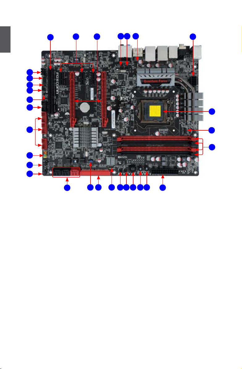
1-2 Layout
1
8
9
10
11
12
13
34
7
6
5
2
1
30
14
15
16
17
18
19
1. 8-pin ATX 12V Power Connector
2. SPDIF-OUT2 Connector
3. SYS_FAN3 Header
4. FAN1 Header
5. PCI Express x16 Slots
6. PCI Express x1 Slots
7. PCI Slot
8. CD_IN Connector
9. Front Audio Connector
10. SPDIF-OUT3 Connector
11. SYS_FAN1 Header
12. CLear CMOS Jumper
13. 1394a Connector
14. Front USB Connectors
15. Front Panel Connector
2120
27
24
22 23 25 26
16. Reset Button
17. Power On Button
18. SATA Connectors
19. BIOS_Select Jumper
20. IDE Connector
21. Speaker Connector
22. SYS_FAN2 Header
23. FAN2 Header
24. OC_Switch1 Button
25. OC_Switch2 Button
26. OC_Switch3 Button
27. 24-pin ATX Power Connector
28. DDR3 DIMM Slots
29. CPU_FAN1 Header
30. LGA1155 CPU Socket
29
28
Note : The above motherboard layout is for reference only, please refer to the physical
motherboard for detail.
4
Page 12
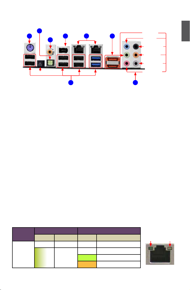
1-3 Back Panel Connectors
Optical
S/PDIF Out
PS/2 Port
3
Coaxial
1
S/PDIF Out
1394a Port
4
5
LAN Ports
6
External
SATA Ports
7
Line Out
1
Line In
Rear Speaker
Subwoofer
Side Speaker
Clear CMOS Button
2
USB Ports
Microphone In
8
Audio Ports
1. PS/2 Keyboard Port
Use this port (purple) to connect a PS/2 keyboard.
2. USB Ports
The USB port supports the USB 3.0 (blue) /2.0/1.1 specication. Use this port for USB devices
such as an USB keyboard/mouse, USB printer, USB ash drive and etc. But you need to install
the USB 3.0 driver in the Driver CD before using it.
3. Optical S/PDIF Out Port
This port provides digital audio out to an external audio system that supports digital optical
audio.
4. Coaxial S/PDIF Out Port
This connector provides digital audio out to an external audio system that supports digital co-
axial audio. Before using this feature, ensure that your audio system provides a coaxial digital
audio in connector.
5. 1394a Port
This port is used to connect a 1394a device.
6. LAN Ports
The Ethernet LAN port provides Internet connection at up to 10/100/1000Mb/s data rate.
LAN Type
Left: Active Right: Link
Status Description Status Description
Active
LED
Off No Link Off No Link
1000M
Green
Blinking
Data
Activity
Off 10Mb/s Connection
Green 100Mb/s Connection
Orange 1000Mb/s Connection
5
Link
LED
Page 13
7. External SATA Ports (Only for Rattler)
To connect external SATA device(s) to your system by expanding the internal SATA port(s) to
the chassis back panel. External SATA device shall provide power by its own.
1
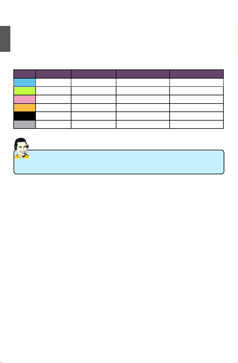
8. Audio Ports
For the denition of each audio port, please refer to the table below :
Port 2-channel 4-channel 5.1-channel 7.1-channel
Blue Line In Line In Line In Line In
Green Line Out Front Speaker Out Front Speaker Out Front Speaker Out
Pink Microphone In Microphone In Microphone In Microphone In
Orange - - Center/Subwoofer Out Center/Subwoofer Out
Black - Rear Speaker Out Rear Speaker Out Rear Speaker Out
Grey - - - Side Speaker Out
We will introduce the Clear CMOS Button in the
chapter.
OnBoard Button section of the
following
6
Page 14

This chapter introduces the hardware installation process, including
the installation of the CPU, memory, power supply, slots, pin
headers and the mounting of jumpers. Caution should be exercised
during the installation of these modules. Please refer to the
motherboard layout prior to any installation and read the contents in
this chapter carefully.
This chapter includes the following information :
■ Install the CPU and CPU Cooler
■ Install the Memory
■ Install an Expansion Card
■ Install other Internal Connectors
■ Jumpers
■ OnBoard Button
■ OnBoard Debug LED
Please visit the following website for more supporting information about your motherboard.
CPU Support List:
http://www.foxconnsupport.com/cpusupportlist.aspx
Memory, VGA Compatibility List:
http://www.foxconnsupport.com/complist.aspx
Page 15
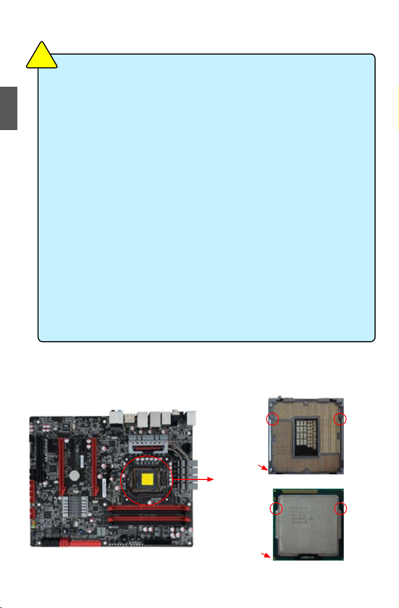
2-1 Install the CPU and CPU Cooler
N
O
I
T
U
A
C
!
Read the following guidelines before you begin to install the CPU :
■ Make sure that the motherboard supports the CPU.
■ Always turn off the computer and unplug the power cord from the power supply before
2
installing the CPU to prevent hardware damage.
■ Locate the pin one of the CPU. The CPU cannot be inserted if oriented incorrectly. (Or
you may locate the notches on both sides of the CPU and alignment keys on the CPU
socket.)
■ Apply an even and thin layer of thermal grease on the surface of the CPU.
■ Do not turn on the computer if the CPU cooler is not installed, otherwise overheating
and damage of the CPU may occur.
■ Set the CPU host frequency in accordance with the CPU specications. It is not
recommended that the system bus frequency be set beyond hardware specications
since it does not meet the standard requirements for the peripherals. If you wish to
set the frequency beyond the standard specications, please do so according to your
hardware specications including the CPU, graphics card, memory, hard drive, etc.
Hyper-Threading Technology System Requirements:
(Go to Intel's website for more information about the Hyper-Threading Technology)
■ An Intel® CPU that supports HT Technology
■ A chipset that supports HT Technology
■ An operating system that is optimized for HT Technology
■ A BIOS that supports HT Technology and has it enabled
Install the CPU
Locate the alignment keys on the motherboard CPU socket and the notches on the CPU.
LGA1155 CPU Socket
Alignment Key
Pin-1 corner of
the CPU Socket
LGA1155 CPU
Notch
Pin-1 triangle
marking of CPU
8
8
Page 16
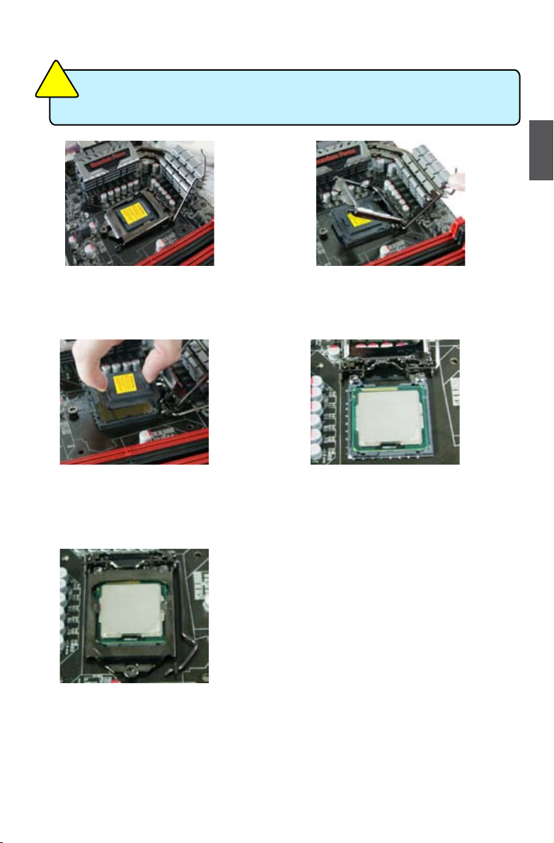
Follow the steps to install the CPU onto the CPU socket :
N
O
UTI
CA
!
Before installing the CPU, make sure to turn off the computer and unplug the power
cord from the power outlet to prevent damage to the CPU.
2
1. Release the CPU socket lever.
3. Remove protective socket cover.
2. Lift the metal cover on the CPU
socket.
4. Check pin one marking (triangle)
with the pin one corner of the CPU
socket, align the CPU notches with
the socket alignment keys and gently
put the CPU onto the socket.
5. When CPU is properly seated,
replace the metal cover and push the
CPU socket lever back to its locked
position.
9
9
Page 17
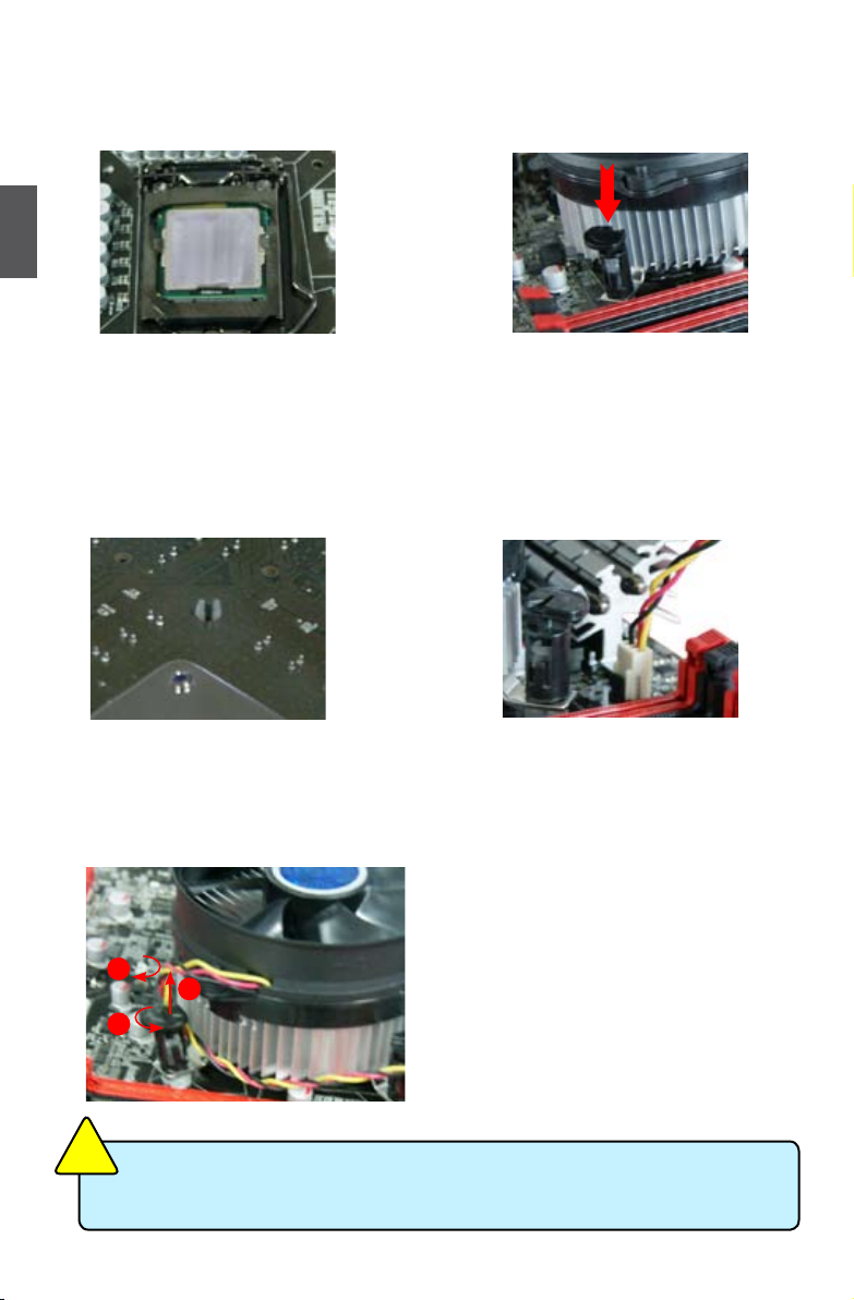
Install the CPU Cooler
Follow the steps below to correctly install the CPU cooler on the motherboard.
2
1. Apply and spread an even thermal
grease on the surface of CPU.
3. Chec k the sol de r side of the
motherboard, the push pin should be
xed as depicted in the picture.
3
2
1
2. Place the four bolts of the CPU
cooler to the holes of the motherboard,
push them straight down from the top,
and the bolts will be fastened on the
motherboard. That's it.
4. Attach t he 4-wire C PU cooler
connector to the CPU FAN header
on the motherboard .
Release bolts of CPU cooler from
motherboard :
1.Tu r n i n g th e p u s h pi n (b o l t )
along with the direction of arrow
(counterclockwise).
2. Pull the push pin straight up.
3. Turning push pin clockwise to its
default position.
N
O
I
T
U
A
!
C
Use extreme care when removing the CPU cooler because the thermal grease may
adhere to the CPU. Inadequately removing the CPU cooler may damage the CPU.
10
10
Page 18
2-2 Install the Memory
N
O
I
T
U
A
C
!
Read the following guidelines before you begin to install the memory :
■ Make sure that the motherboard supports the memory. It is recommended that memory
of the same capacity, brand, speed, and chips be used.
■ Always turn off the computer and unplug the power cord from the power outlet before
installing the memory to prevent hardware damage.
■ Memory modules have a foolproof design. A memory module can be installed in only
one direction. If you are unable to insert the memory, switch the direction.
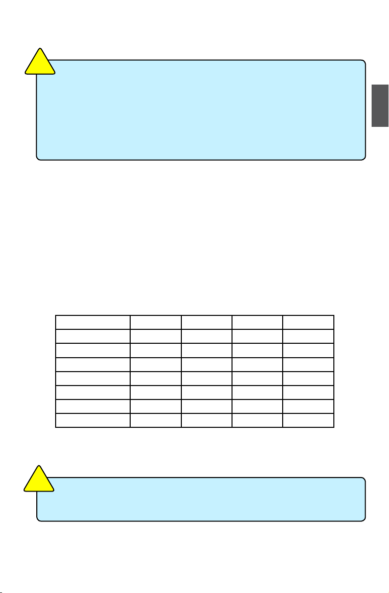
Dual Channel Memory Conguration
This motherboard provides four DDR3 memory sockets and supports Dual Channel Technology.
When memory is installed, the BIOS will automatically check the memory in your system.
Four DDR3 memory sockets are divided into two channels:
Channel 0 : DIMM1, DIMM3
Channel 1 : DIMM2, DIMM4
The combinations of DIMM modules are :
2
DIMM1 DIMM2 DIMM3 DIMM4
Single Channel DS/SS - - -
Single Channel DS/SS - DS/SS -
Single Channel - DS/SS - -
Single Channel - DS/SS - DS/SS
Dual Channel DS/SS DS/SS - -
Dual Channel - - DS/SS DS/SS
Dual Channel DS/SS DS/SS DS/SS DS/SS
(DS : Dual Side, SS : Single Side, - : No Memory)
N
O
I
T
U
A
C
!
It is recommended that memory of the same capacity, brand, speed, and chips be
used and please select dual channel rst to achieve optimum performance.
11
11
Page 19
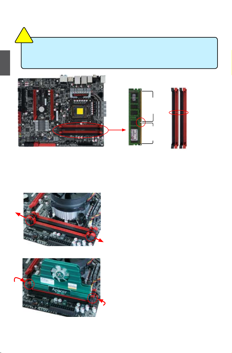
Installing a Memory
N
O
I
T
U
A
C
!
■ Before installing a memory module, make sure to turn off the computer and unplug the
power cord from the power outlet to prevent damage to the memory module. Be sure to
2
install DDR3 DIMMs on this motherboard.
144-Pin
96-Pin
Notch
If you take a look at front side of memory module, it has asymmetric pin counts on both sides separated
by a notch in the middle, so it can only t in one direction. Follow the steps below to correctly install
your memory modules into the sockets.
Step 1:
Spread the clips at both ends of the memory socket.
Place the memory module onto the socket, then put your
ngers on top edge of the module, and push it down rmly
and seat it vertically into the memory socket.
Step 2:
The clips at both ends of the socket will snap into place
when the memory module is securely inserted.
12
12
Page 20
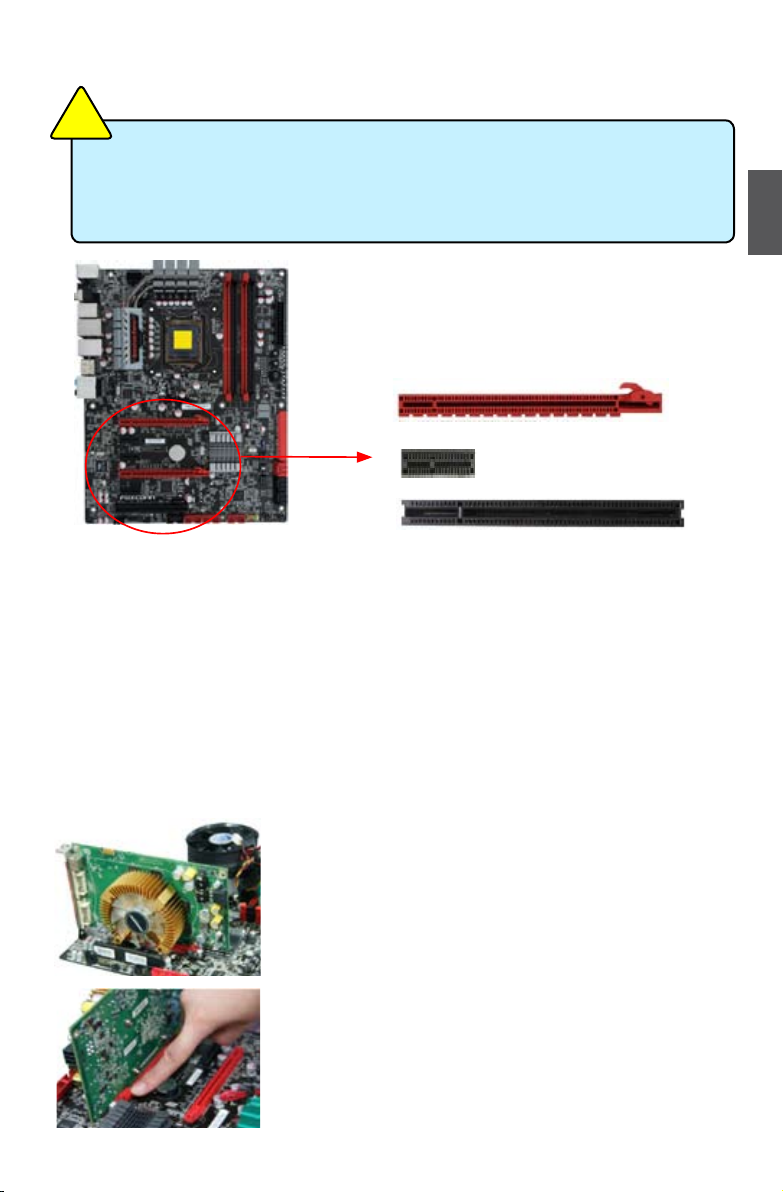
2-3 Install an Expansion Card
N
O
I
T
U
A
C
!
■ Make sure the motherboard supports the expansion card. Carefully read the manual
that came with your expansion card.
■ Always turn off the computer and unplug the power cord from the power outlet before
installing an expansion card to prevent hardware damage.
PCI Express x16
PCI Express x4
PCI
Follow the steps below to correctly install your expansion card in the expansion slot.
1. Locate an expansion slot that supports your card. Remove the metal slot cover from the chassis
back panel.
2. Align the card with the slot, and press down on the card until it is fully seated in the slot.
3. Make sure the metal contacts on the card are completely inserted into the slot.
4. Secure the card's metal bracket to the chassis back panel with a screw.
5. After installing all expansion cards, replace the chassis cover.
6. Turn on your computer. If necessary, go to BIOS Setup to make any required BIOS changes for
your expansion card(s).
7. Install the driver provided with the expansion card in your operating system.
Installing and Removing a PCI Express x16 Graphics Card :
2
• Installing a Graphics Card:
Gently insert the graphics card into the PCI Express x16 slot. Make
sure the graphics card is locked by the latch at the end of the PCI
Express x16 slot.
• Removing the Card:
Push the latch at the end of the PCI Express x16 slot to release
the card and then pull the card straight up from the slot.
13
13
Page 21
2-4 Install other Internal Connectors
Power Connectors
This motherboard uses an ATX power supply. In order not to damage any device, make sure all the
devices have been installed properly before applying the power supply.
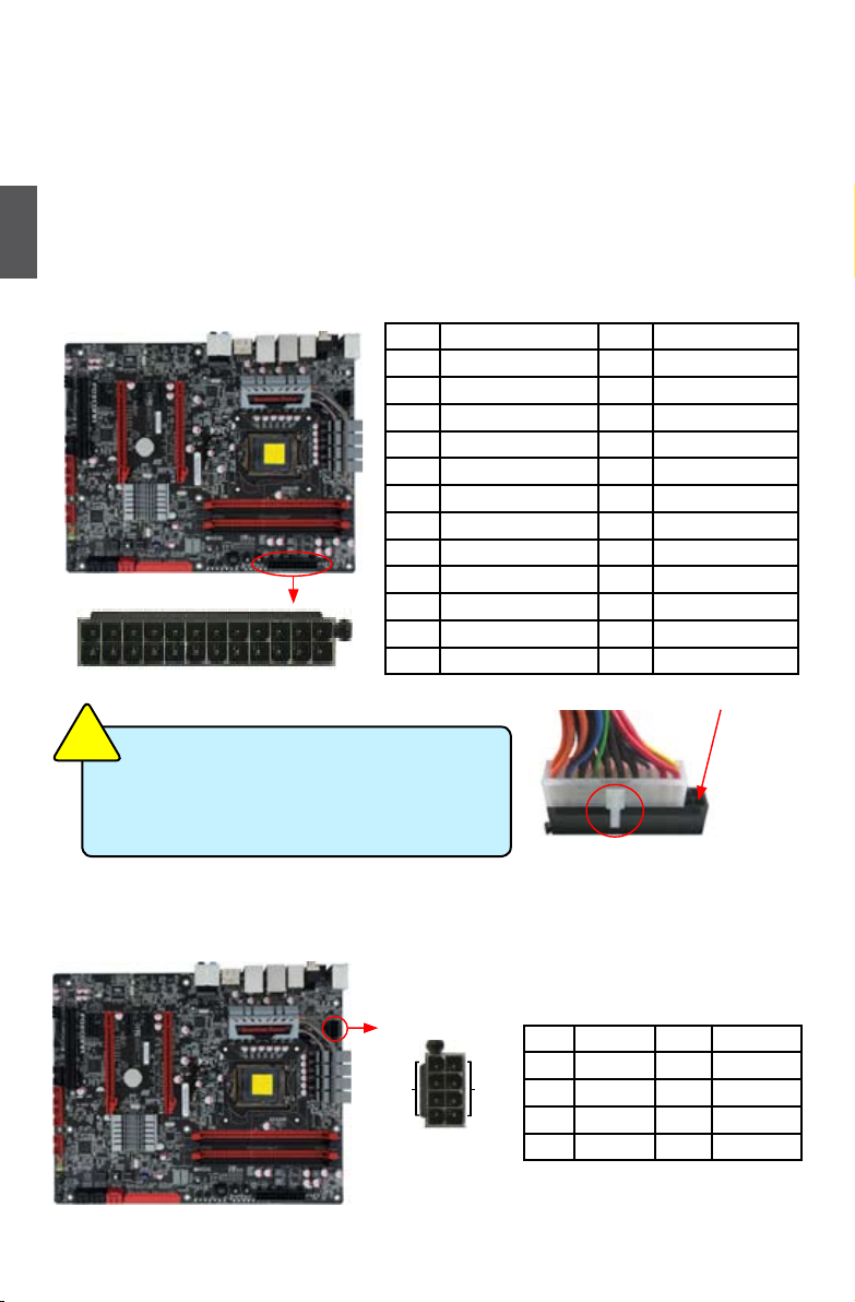
24-pin ATX Power Connector : PWR1
2
PWR1 is the ATX power supply connector. Make sure that the power supply cable and pins are
properly aligned with the connector on the motherboard. Firmly plug the power supply cable into the
connector and make sure it is secure.
Pin # Denition Pin # Denition
1 3.3V 13 3.3V
2 3.3V 14 -12V
3 GND 15 GND
4 +5V 16 PS_ON(Soft On/Off)
5 GND 17 GND
6 +5V 18 GND
7 GND 19 GND
8 Power Good 20 NC
9 +5V SB(Stand by +5V) 21 +5V
24 13
12
N
O
I
T
U
A
C
!
PWR1
We recommend you using a 24-pin power supply.
1
If you are using a 20-pin power supply, you need
to align the ATX power connector according to
the picture.
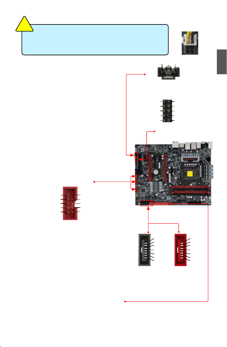
8-pin ATX 12 V Power Connector : PWR2
Connect the 8-pin ATX 12V power supply to PWR2 and provides power to the CPU.
10 +12V 22 +5V
11 +12V 23 +5V
12 3.3V 24 GND
Pin No. 24
20-Pin Power
+12V
5
PWR2
14
14
1
48
Pin # Denition Pin # Denition
GND
1 GND 5 +12V
2 GND 6 +12V
3 GND 7 +12V
4 GND 8 +12V
Page 22
N
O
I
T
U
A
C
!
Connect a 4-pin
power plug
We recommend you using an 8-pin ATX 12V power supply. If
you are using a 4-pin power supply, you need to align the ATX
power connector according to the picture on the right.
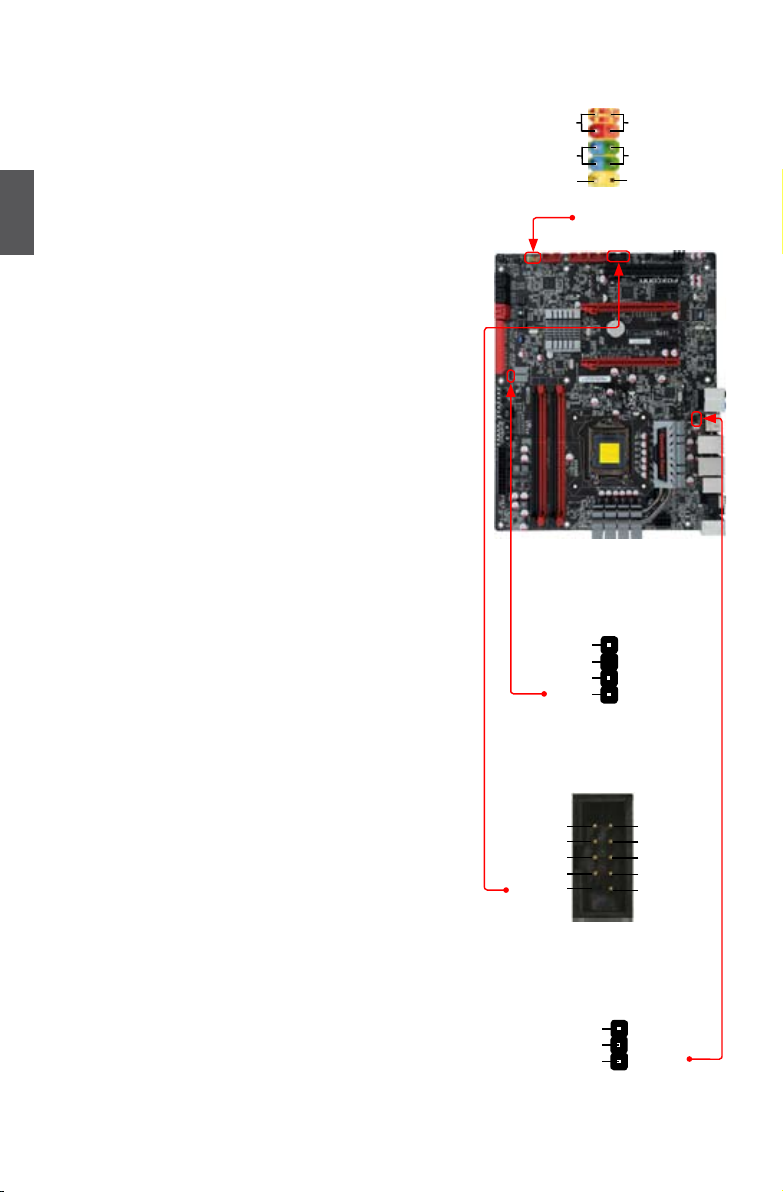
Audio Connector : CD_IN
CD_IN is a Sony standard audio connector, it can
be connected to a CD/DVD-ROM drive through a
CD/DVD audio cable.
Audio Connector : F_AUDIO
The audio connector supports HD Audio standard. It
provides the Front Audio output choice.
USB Connectors : F_USB1/2/3
In addition to the eight USB ports on the rear panel,
this product also provides three 10-pin USB headers
on its motherboard. By connecting through USB cables
with them, user can quickly expand another six USB
ports on the front panel.
1 2
VCC
GND
EMPTY
D-
D+
VCC
DD+
GND
GND
109
F_USB 1/2/3
Serial ATA Connectors : SATA_1/2/3/4/5/6
The Serial ATA connector is used to connect with
SATA Hard Disk or CD devices which support this
feature. The black connectors support current Serial ATA II interface and allows up to 300MB/s data
transfer rate.The two red connectors support the
current SATA III interface and allows upto 600MB/s
data transfer rate.
CD_L GND CD_R
1
CD_IN
A_MIC2_L
A_MIC2_R
A_LINE2_R
SENSE_SEND
A_LINE2_L
1
F_AUDIO
1
GND
TX+
TXGND
RXRX+
GND
SATA3_4/SATA5_6
2
AUD_GND
PRESENCEJ
SENSE1_RETURN
EMPTY
SENSE2_RETURN
109
SATA1_2
1
GND
TX+
TXGND
RXRX+
GND
2
IDE Connector : PIDE
With the provided Ultra DMA IDE ribbon cable, you
can connect to any IDE type of hard disk and CD/DVD
ROM/RW drive.
15
15
Page 23
Front Panel Connector : FP1
This motherboard includes one connector for connecting
the front panel switch and LED Indicators.
Hard Disk LED Connector (HDD-LED)
Connect to the chassis front panel IDE indicator LED. It
indicates the active status of the hard disks. This 2-pin
2
connector is directional with +/- sign.
Reset Switch (RESET-SW)
Attach the connector to the Reset switch on the front
panel of the case; the system will restart when the
switch is pressed.
Power LED Connector (PWR-LED)
Connect to the power LED indicator on the front panel
of the chassis. The Power LED indicates the system’s
status. When the system is in operation (S0 status),
the LED is on. When the system gets into sleep mode
(S1) , the LED is blinking; When the system is in S3/S4
sleep state or power off mode (S5), the LED is off. This
2-pin connector is directional with +/- sign.
Power Switch Connector (PWR-SW)
Connect to the power button on the front panel of the
chassis. Push this switch allows the system to be turned
on and off rather than using the power supply button.
Speaker Connector : SPEAKER
The speaker connector is used to connect speaker of the
chassis.
HDD-LED
RESET-SW
EMPTY
1
+
-
NC
10
9
FP1
PWR
NC
SPKJ
SPEAKER
2
+
-
1
2
3
4
PWR-LED
PWR-SW
EMPTY
1394a Connector : F_1394
The 1394a expansion cable can be connected to either
the front (provided that the front panel of your chassis is
equipped with the appropriate interface) or real panel of
the chassis.
S/PDIF Connector : SPDIF_OUT2
The connector is used for S/PDIF output.
16
16
TPA+
GND
TPB+
+12V
EMPTY
SPDIF_OUT
SPDIF_OUT2
1
10
9
F_1394
+5V
GND
2
TPAGND
TPB+12V
GND
1
2
3
Page 24
S/PDIF Connector : SPDIF_OUT3
The connector is used for S/PDIF output.
SPDIF_OUT
GND
1
2
SPDIF_OUT3
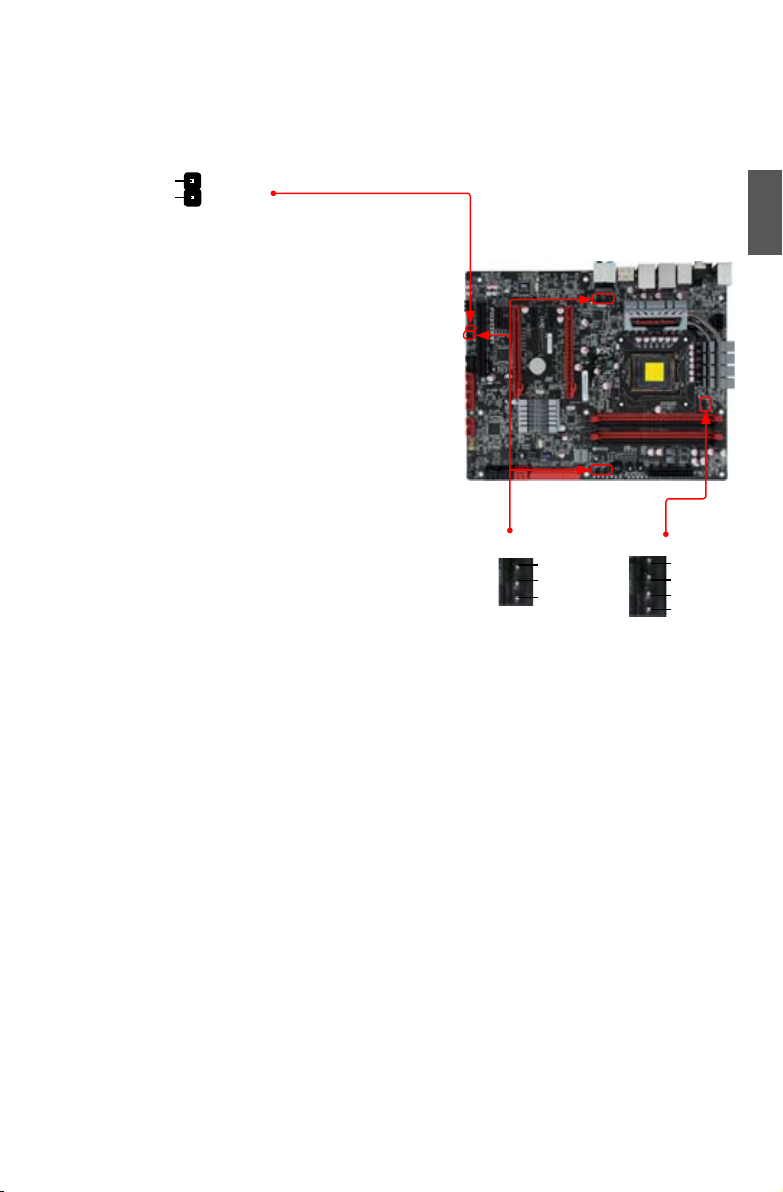
Fan Connectors : CPU_FAN, FAN1/2,
SYS_FAN1/2/3
There are six main fan headers on this motherboard. The
fan speed can be controlled and monitored in “Quantum
BIOS” section of the BIOS Setup. These fans can be
automatically turned off after the system enters
S3, S4 and S5 sleeping states.
1
GND
+12V
NC
FAN1/2,
SYS_FAN1/2/3
1
CPU_FAN1
GND
POWER
SENSE
CONTROL
2
17
17
Page 25
2-5 Jumpers
For some features needed, users can change the jumper settings on this motherboard to modify them.
This section explains how to use the various functions of this motherboard by changing the jumper
settings. Users should read the following content carefully prior to modifying any jumper setting.
Description of Jumpers
1. For any jumper on this motherboard, pin 1 can be identied by the bold silkscreen next to it.
2
However, in this manual, pin 1 is simply labeled as “1”.
2. The following table explains different types of the jumper settings. "Closed" means placing a jumper
cap on the two pins to temporarily short them. The shorting can also be done by touching two
pins by a screwdriver for a few seconds, but using jumper cap is recommended. It can prevent
hazardous ESD (Electrical Static Discharge) problem.
Jumper Diagram Denition Description
1
1
1
1
1
1
Clear CMOS Jumper: CLR_CMOS
The motherboard uses CMOS RAM to store the basic hardware information (such as BIOS data,
date, time information, hardware password...etc.). Clear CMOS data is the fast way to go back to
factory default when the BIOS settings were mistakenly modied.
Closed Set Pin 1 and Pin 2 closed
Open Set Pin 1 and Pin 2 Open
1-2 Set Pin 1 and Pin 2 closed
2-3 Set Pin 2 and Pin 3 closed
The steps to clear CMOS data are :
1. Turn off the computer, unplug the power cord from the power outlet.
2.
Put a metal object(such as a screwdriver) onto pins 1-2 to short them. This will clear CMOS data.
3. After a few seconds, remove the metal object to leave the Pins 1-2 open.
4. Plug in the power cord to your computer and turn it on.
5. Go to BIOS Setup to congure new system as described in next chapter.
Clear
Normal
(Default)
I
N
N
G
R
A
!
W
CLR_CMOS
1
2
1
2
■ Disconnect the power cable before adjusting the jumper settings.
■ Do not clear the CMOS while the system is turned on.
18
18
Page 26
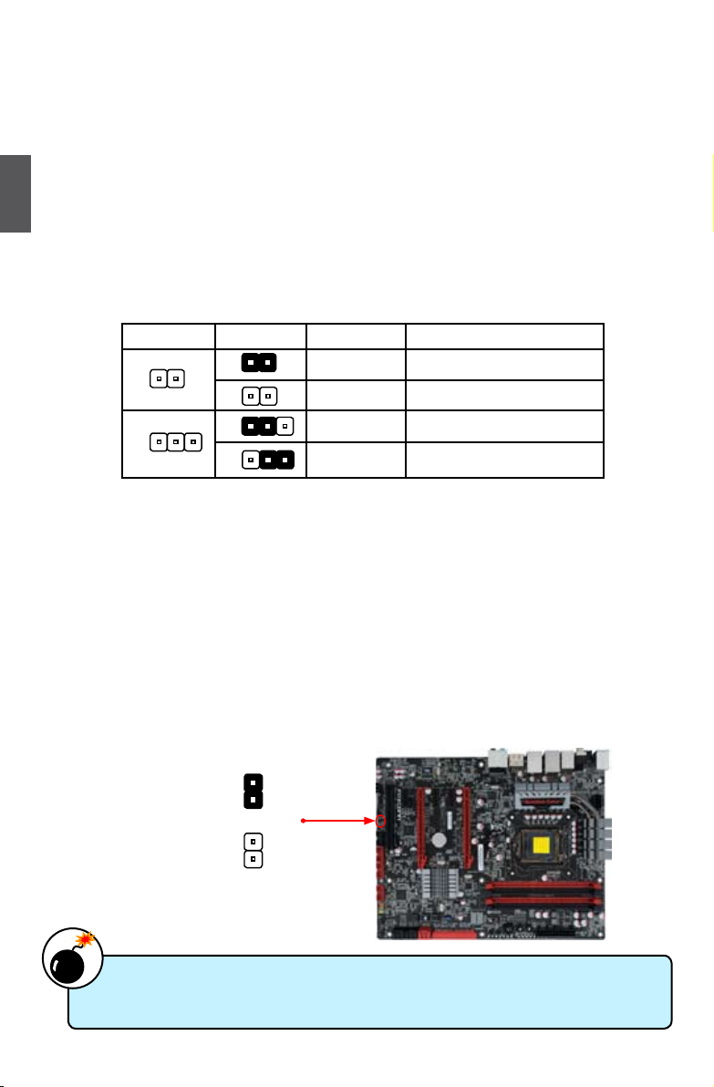
BIOS Select Jumper: BIOS_SELECT
The jumper is used to select a BIOS ROM to boot from. You can refer to the following table for
reference.
How to recover BIOS
When one of BIOS has been
damaged, you can use another
workable BIOS to boot to DOS.
Then switch the jumper to change
to your bad BIOS.And then run the
“FPT” reash program.
1
(Default)
2
3
1
2
3
SPI 1
SPI 2
BIOS_SELECT
Denition Description Function
1-2(default) Set Pin 1 and Pin 2 closed Select SPI1 (BIOS ROM 1)
N
O
I
T
U
A
C
!
2-3 Set Pin 2 and Pin 3 closed Select SPI2 (BIOS ROM 2)
■ Besides you are doing the BIOS recovery procedure, don’t change the jumper setting
when system is power on.
2-6 OnBoard Button
2
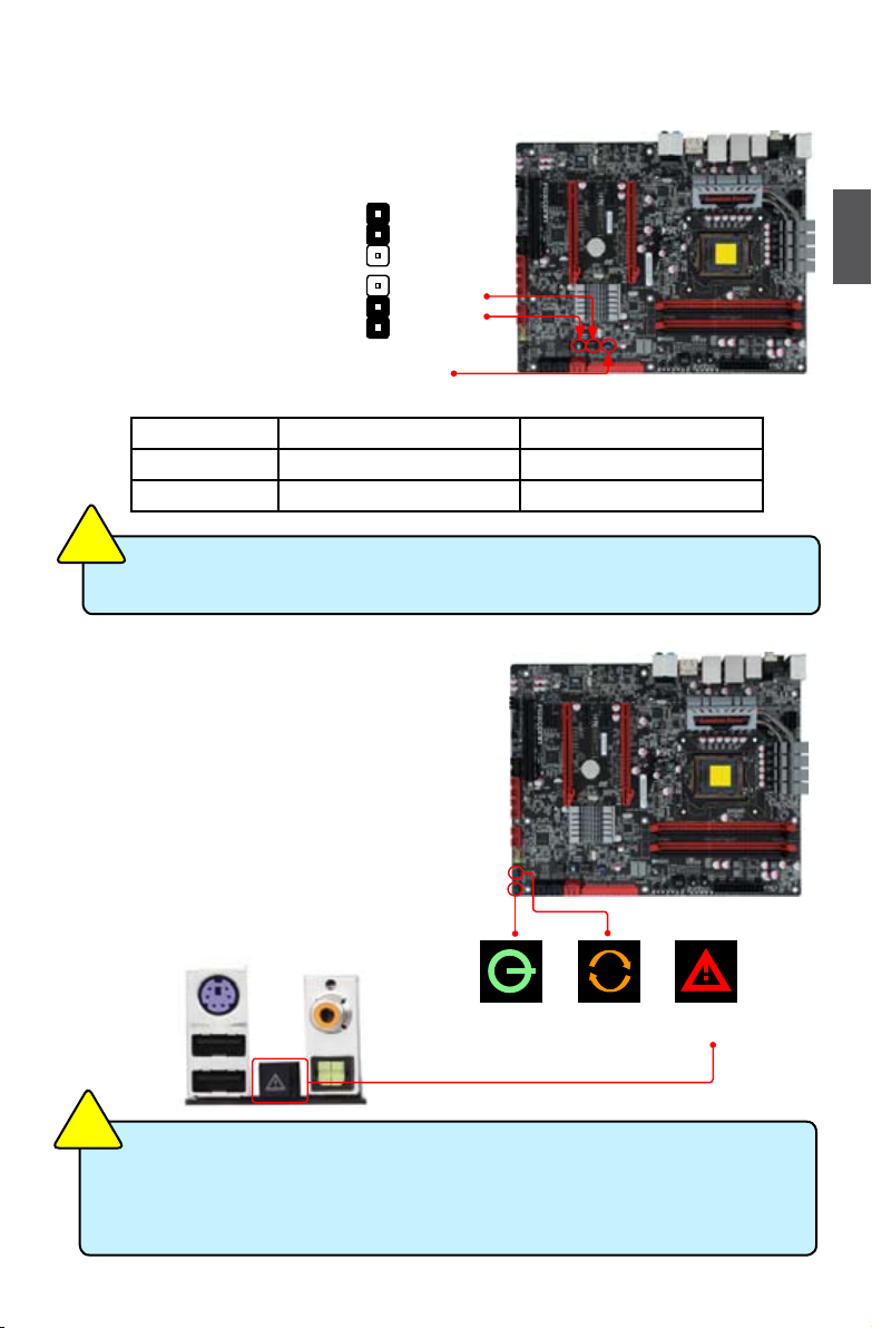
Power on Button: PWR_ON
Push the power on button to power on the system.
Reset Button: RST
Push the reset button to reboot the system.
Clear CMOS Button: CLS_CMOS
Turn off the AC power supply, press the CLS_CMOS
button and hold there for a couple of seconds to clear
CMOS.
PWR_ON RST CLS_CMOS
N
O
I
T
U
A
C
!
■ Make sure the power supply is turned off before pressing the CLS_CMOS button to
clear CMOS.
■ Push down the CLS_CMOS button and hold it there for a couple of seconds to clear
the CMOS completely, then release.
19
19
Page 27
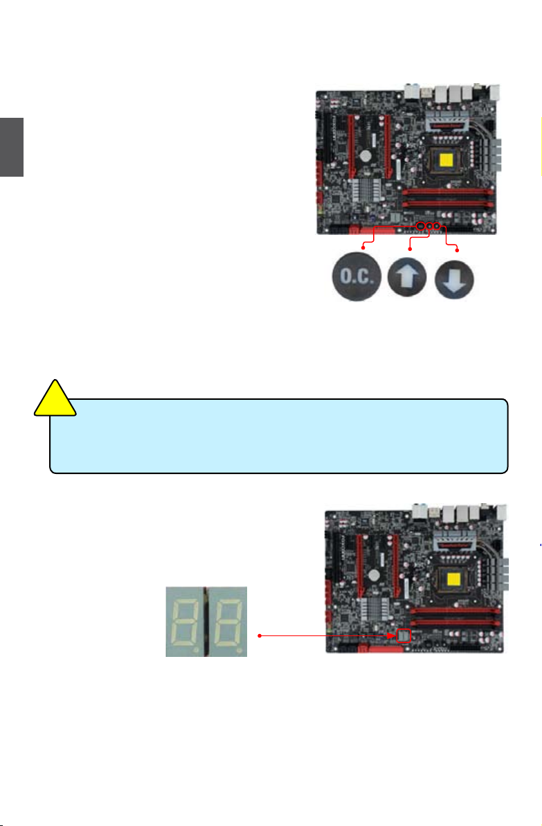
OC Switch Button: OC_SW1/2/3
You could press the three buttons to adjust the CPU
clock directly, without to enter BIOS setup or any software. This process will not use any system resource,
so there is no effect to the system performance.
■ Normally the OC function is disabled. All the
2
led lights on these buttons will be turned off.
■ During booting, when the boot screen appears, press the OC_SW1 button to enter
the OC mode and the led lights will turn
on. At this moment the debug led will show
“0.0”. It means the CPU current clock is
100MHz(Default).
■ In the OC mode, pressing the OC_SW2 button will increase the CPU clock by 1 MHz per
step, and the debug led code will increase 0.1
at the same time. The debug led code “0.1”
means the CPU clock is 101 MHz.
■ In the OC mode, pressing the OC_SW3 button will decrease the clock by 1 MHz per step.
This project does not support a clock lower
than 100MHz.
N
O
I
T
U
A
C
!
■ When the OC function is enabled by OC_SW1, the overclocking items in BIOS or
software will be availble. It is controlled by the onboard buttons completely.
■ We do not guarantee the system will keep stable status In the overclocking mode.
OC_SW1 OC_SW2 OC_SW3
2-7 OnBoard Debug LED
2-digital LED readout displays hardware status and
enables quick error diagnosis.
20
20
Page 28
This chapter tells how to change system settings through
the BIOS Setup menus. Detailed descriptions of the BIOS
parameters are also provided.
You have to run the Setup Program when the following cases
occur :
1. An error message appears on the screen during the system
Power On Self Test (POST) process.
2. You want to change the default CMOS settings.
This chapter includes the following information :
■ Enter BIOS Setup
■ Main
■ Advanced
■ Chipset
■ Boot
■ Security
■ Save & Exit
■ Quantum BIOS
Since BIOS could be updated some other times, the BIOS information described
in this manual is for reference only. We do not guarantee the content of this
manual will remain consistent with the newly released BIOS at any given time in
the future. Please visit our website for updated manual if it is available.
Page 29

Enter BIOS Setup
The BIOS is the communication bridge between hardware and software, correctly setting up the
BIOS parameters is critical to maintain optimal system performance. Power on the computer,
when the message "Press TAB to show POST screen, DEL to enter SETUP" appears at the
bottom of the screen, you can press <DEL> key to enter Setup.
N
O
I
T
U
A
C
!
We do not suggest that you change the default values in the BIOS Setup, and we
shall not be responsible for any damage which resulted from the change you made.
3
Use the arrow right/left keys to select a specic function and go to the submenu. Each function is
explained below:
Main
It displays the basic system conguration, such as CPU Name, memory size, system date,
time and so on. They all can be viewed or set up through this menu.
Advanced
The advanced system features can be set up through this menu.
Chipset
The values for the chipset can be changed through this menu, and the system performance
can be optimized.
Boot
Boot features can be set up through this menu. You can set the boot device priority and enable
"Quiet Boot" feature here.
Security
The Administrator/User password can be set up through this menu to prevent unauthorized
use of your computer. If you set a password, the system will ask you to key in correct
password before boot or access to Setup.
Save&Exit
The optimal performance settings can be loaded through this menu. However, it may offer
better performance in some ways (such as less I/O cards, less memory ...etc.), still, it may
cause problem if you have more memory or I/O cards installed. It means, if your system
loading is heavy, set to optimal default may sometimes come out an unstable system. What
you need now is to adjust BIOS setting one by one, trial and error, to nd out the best setting
for your current system. You also can save or discard the changes and exit BIOS setup here.
Quantum BIOS
Some special proprietary features can be set up through this menu.
22
Page 30
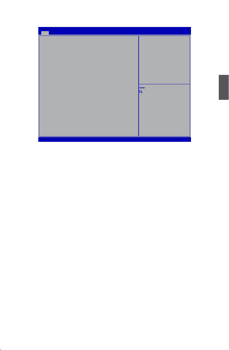
Main
Main Advanced Chipset Boot Security Save & Exit Quantum BIOS
Main
BIOS Information
BIOS Vendor American Megatrends
BIOS Build Date 12/09/2010 09:44:32
System BIOS Version D18
Model Name Rattler
CPU Information
Genuine Intel(R) CPU 0 @ 3.00GHz
Processor Stepping 206a3
Microcode Revision 8
Processor Cores 4
Memory Information
Total Memory 1024 MB (DDR3 1333)
System Date [Sat 12/10/2005]
System Time [17:44:01]
Access Level Administrator
BIOS Information
► BIOS Vendor
This item shows the BIOS vendor information.
► BIOS Build Date
This item shows the BIOS building date and time.
► System BIOS Version
It displays the current BIOS version. User can check this information and discuss with the eld
service people if a BIOS upgrade is needed.
► Model Name
This item shows the model name of this product.
CPU Information
► Genuine Intel(R) CPU 0 @ 3.00GHz
This item shows the current CPU name.
► Processor Stepping
This item shows the processor stepping value.
► Microcode Revision
This item shows the microcode revision number.
► Processor Cores
This item shows the CPU number.
Memory Information
► Total Memory
This item displays the total memory size. The size is depending on how many memory mod-
ules are installed in your system before powering on.
► System Date
<weekday><month><date> <year> format.
Day—weekday from Sun. to Sat., this message is automatically displayed by BIOS (Read
Aptio Setup Utility - Copyright (C) 2010 American Megatrends, Inc.
Set the Date. Use Tab to
switch between Date elements.
→ ←: Select Screen
↑ ↓: Select Item
Enter: Select
+/-: Change Opt.
F1: General Help
F2: Previous Values
F3: Optimized Defaults
F4: Save & Exit
ESC: Exit
Version 2.10.1208. Copyright (C) 2010 American Megatrends, Inc.
23
3
Page 31

Only).
Month—month from 1 to 12.
Date—date from 1 to 31.
Year—year, set up by users.
Use [ENTER], [TAB] or [SHIFT-TAB] to select a eld. Use [+] or [-] to input the value.
► System Time
This item allows you to congure the desired time. Use [ENTER], [TAB] or [SHIFT-TAB] to
select a eld. Use [+] or [-] to input the value.
The three elds of the setting are <hour> : <minute> : <second> respectively.
► Access Level
3
It displays your current access level. If you enter system with a user password, it will dispaly
“User”. If no password is set or you enter system with administrator password, this item will
dispaly “Administrator”.
24
Page 32
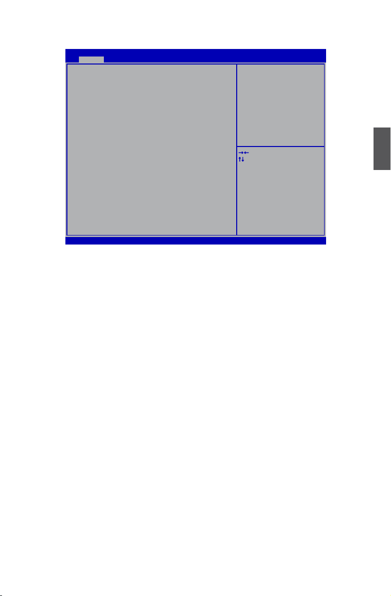
Advanced
Main Advanced Chipset Boot Power Health Security Save & Exit
Advanced
Legacy OpROM Support
Launch LAN 1 PXE OpROM [Disabled]
Launch LAN 2 PXE OpROM [Disabled]
Launch Storage OpROM [Enabled]
80h Debug Code Send to [LPC Bus]
► PCI Subsystem Settings
► ACPI Settings
► Onboard Device
► SATA Configuration
► USB Configuration
► CMOS
Aptio Setup Utility - Copyright (C) 2010 American Megatrends, Inc.
Enable or Disable Boot Option
for Legacy Network Devices.
→ ←: Select Screen
↑ ↓: Select Item
Enter: Select
+/-: Change Opt.
F1: General Help
F2: Previous Values
F3: Optimized Defaults
F4: Save & Exit
ESC: Exit
Version 2.10.1208. Copyright (C) 2010 American Megatrends, Inc.
Legacy OpROM Support
► Launch LAN 1/2 PXE OpROM
This item is used to enable or disable boot option for legacy network devices.
► Launch Storage OpROM
This item is used to enable or disable boot option for legacy mass storage devices with option
ROM.
► 80h Debug Code Send to
The legacy I/O 80h debug port message will send to LPC bus or PCI bus as your selection.
► PCI Subsystem settings/ACPI Settings/Onboard Device/SATA Conguration/Thermal
Conguration/USB Conguration/CMOS
Press [Enter] to go to the submenu.
3
25
Page 33

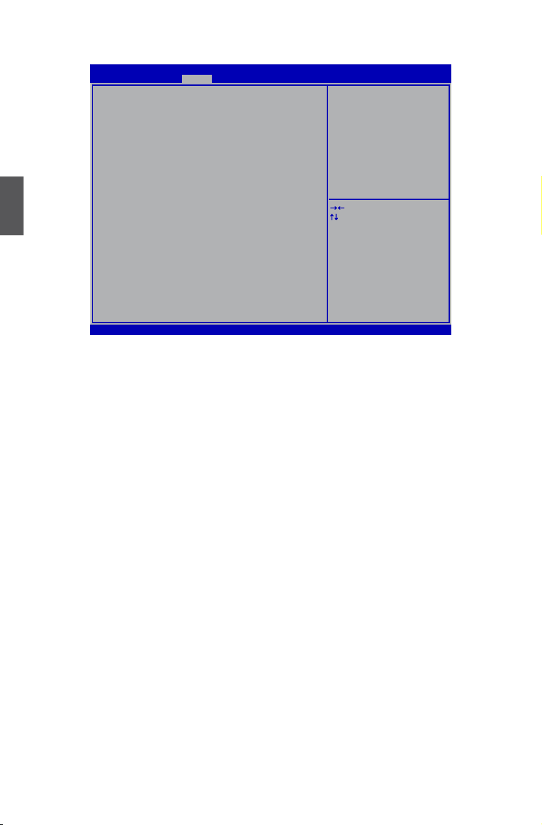
PCI Subsystem Settings
Advanced
PCI Bus Driver Version V 2.03.00 In case of multiple Option
PCI ROM Priority [EFI Compatible ROM] ROMs(Legacy and EFI
Compatible), species what
PCI Common Settings PCI Option ROM to launch.
PCI Latency Timer [32 PCI Bus Clocks]
VGA Palette Snoop [Disabled]
PERR# Generation [Disabled]
SERR# Generation [Disabled]
PCI Express Device Settings
Relaxed Ordering [Disabled]
Extended Tag [Disabled]
3
No Snoop [Enabled]
Maximum Payload [Auto]
Maximum Read Request [Auto]
PCI Express Link Settings
ASPM Support [Disabled]
WARNING: Enabling ASPM may cause some
PCI-E devices to fail
Extended Synch [Disabled]
Aptio Setup Utility - Copyright (C) 2010 American Megatrends, Inc.
→ ←: Select Screen
↑ ↓: Select Item
Enter: Select
+/-: Change Opt.
F1: General Help
F2: Previous Values
F3: Optimized Defaults
F4: Save & Exit
ESC: Exit
Version 2.10.1208. Copyright (C) 2010 American Megatrends, Inc.
► PCI Bus Driver Version
This item shows the PCI bus driver version information.
► PCI ROM Priority
This item is used to specify what PCI option ROM to launch. The default option is [EFI Com-
patible ROM].
PCI Common Settings
► PCI Legacy Timer
The value you chose will be programmed into PCI legacy timer register.
► VGA Palette Snoop
This item is used to enable or disable VGA palette register snooping.
► PERR# Generation
This item is used to enable or disable the PCI device to generate PERR# or not, when a data
parity error is detected.
► SERR# Generation
This item is used to enable or disable the PCI device to generate an SERR#.
PCI Express Device Settings
► Relaxed ordering
This item is used to enable or disable the PCI Express device relaxed ordering.
► Extended Tag
This item is used to allow the PCI Express devices to use the extended 8-bit tag eld as a
requester or not .
► No Snoop
This item is used to enable or disable the PCI Express device no snoop option.
► Maximum Payload
This item is used to set the maximum payload of PCI Express Device, or you can set [Auto]
to allow system BIOS to select the value.
26
Page 34

► Maximum Read Request
This item is used to set the maximum read request size of PCI Express Device, or you can set
[Auto] to allow system BIOS to select the value.
PCI Express Link Settings
► ASPM Support
You can set the ASPM level here:
[Force L0]: Force all links to L0 state.
[Auto]: BIOS auto congure it.
[Disable]: Disable the ASPM.
► Extended Synch
This item is used to allow generation of extended synchronization patterns.
ACPI Settings
Advanced
ACPI Settings
Enable Hibernation [Enabled]
ACPI Sleep State [S3 (Suspend to RAM)
Lock Legacy Resources [Disabled]
S3 Video Repost [Disabled]
S4 and S5 Wake-Up Power Supply [Disabled]
PS2 KB Wake-Up From S1 and S3 [Enabled]
USB Device Wake-Up Power Supply [Enabled]
PCI(e) Device Wake-Up Power Supply [Disabled]
Aptio Setup Utility - Copyright (C) 2010 American Megatrends, Inc.
Enables or Disables System ability to
Hibernate(OS/S4 Sleep State). This
option may
be not effective with some OS.
→ ←: Select Screen
↑ ↓: Select Item
Enter: Select
+/-: Change Opt.
F1: General Help
F2: Previous Values
F3: Optimized Defaults
F4: Save & Exit
ESC: Exit
3
Version 2.10.1208. Copyright (C) 2010 American Megatrends, Inc.
ACPI Settings
► Enable Hibernation
This item is used to enable or disable the hibernation.
► ACPI Sleep State
This item is used to set the energy saving mode of the ACPI function. When you select “S1
(POS)” mode, the power is always on and computer can be resumed at any time. When
you select “S3 (STR)” mode, the power will be down after a period of time. The status of the
computer before it entering STR will be saved in memory, and the computer can quickly return
to previous state when the STR function wakes.When you select “Auto”, it means OS will
automatically take care and assign which mode is the most suitable now.
► Lock Legacy Resources
This item is used to enable or disable lock of legacy resources.
► S3 Video Repost
27
Page 35

This item determines whether to invoke VGA BIOS post on S3/STR resume.
► S4 and S5 Wake-Up Power Supply
when you select [Disabled], only the power button can wake up the system in S4 and S5 state.
► PS2 KB Wake-Up From S1 and S3
This item is used to enable or disable PS2 key board wake up from S1 and S3 state.
► USB Device Wake-Up Power Supply
This item is used to enable or disable USB devices wake up system from S3,S4,S5 state.
When you set “ S4 and S5 Wake-up Power Supply” to [Disabled] and set this item to
[Enabled], only S3 state can be wake up.
► PCI(e) Device Wake-Up Power Supply
3
This item is used to enable or disable PCI and PCIe devices wake up system from S3,S4,S5
state. When you set “ S4 and S5 Wake-up Power Supply” to [Disabled] and set this item to
[Enabled], only S3 state can be wake up.
OnBoard Device
Advanced
Onboard Device Configuration
Realtek 8111E Gigabit LAN 1 [Enabled]
Realtek 8111E Gigabit LAN 2 [Enabled]
Marvell 6121 PATA and eSATA [Enabled]
NEC USB30 Controller(D720200F1) [Enabled]
VIA 1394 Controller(VT6308S) [Enabled]
Aptio Setup Utility - Copyright (C) 2010 American Megatrends, Inc.
Enable or Disable Onboard
Gigabit LAN 1
→ ←: Select Screen
↑ ↓: Select Item
Enter: Select
+/-: Change Opt.
F1: General Help
F2: Previous Values
F3: Optimized Defaults
F4: Save & Exit
ESC: Exit
Version 2.10.1208. Copyright (C) 2010 American Megatrends, Inc.
Onboard Device Configuration
► Realtek 8111E Gigabit LAN 1/2
This item allows you to enable or disable the onboard Gigabit LAN1/2.
► Marvell 6121 PATA and eSATA
This item allows you to enable or disable
the onboard PATA and eSATA ports
Marvell chip to control PATA and eSATA devices.
► NEC USB3.0 Controller(D720200F1)
This item allows you to enable or disable the NEC USB3.0 controller.
► VIA 1394 Controller(VT6308S)
This item allows you to enable or disable the onboard VIA 1394 device.
28
. We are using
Page 36

SATA Conguration
Advanced
SATA Configuration
SATA Mode [AHCI Mode]
Aggressive Link Power Management [Enabled]
SATA Port 0 Not Present
Staggered Spin-up [Disabled]
External SATA Port [Disabled]
Hot Plug [Disabled]
SATA Port 1 Not Present
Staggered Spin-up [Disabled]
External SATA Port [Disabled]
Hot Plug [Disabled]
SATA Port 2 Not Present
Staggered Spin-up [Disabled]
External SATA Port [Disabled]
Hot Plug [Disabled]
SATA Port 3 Not Present
Staggered Spin-up [Disabled]
External SATA Port [Disabled]
Hot Plug [Disabled]
SATA Conguration
► SATA Mode
This item is used to set the operating mode of your SATA ports. Setting options: [IDE Mode];
[AHCI Mode]; [RAID Mode].
[IDE Mode] - This congures the SATA ports to support IDE mode.
[RAID Mode] - When you enable RAID, it means all your SATA drives must also support AHCI.
[AHCI Mode] - The Advanced Host Controller Interface (AHCI) specication describes the reg-
ister level interface for a Host Controller for Serial ATA. The specication includes a description
of the hardware/software interface between system software and the host controller hardware.
AHCI provides more advanced features including SATA features, but some SATA drives may
not support AHCI, unless they are labeled with AHCI support in its specication.
If your motherboard supporting AHCI, and you have a SATA device, which also supports AHCI,
then you can select IDE option to have fair performance (only PATA, SATA level), or you can
select AHCI to get its best performance.
► Aggressive Link Power Management (Appears when “SATA Mode” is set to [AHCI
Mode])
The SATA controller supports auto-generating link requests to the partial or slumber states
when there are no commands to process. This item is used to enable or disable this function.
When enabled, the SATA controller will aggressively enter a lower link power state (partial or
slumber) based upon the setting of the ASP bit (bit 27).
► Serial-ATA Controller 0 (Appears when “SATA Mode” is set to [IDE Mode])
Serial-ATA Controller 0 are the SATA ports 1, 2, 3, 4 of the motherboard. This item allows you
select the mode of the SATA ports. Setting values are: [Disabled], [Compatible], [Enhanced].
► Serial-ATA Controller 1 (Appears when “SATA Mode” is set to [IDE Mode])
Serial-ATA Controller 1 are the SATA ports 5,6 of the motherboard. This item allows you select
the mode of the SATA ports. Setting values are: [Disabled], [Enhanced].
Aptio Setup Utility - Copyright (C) 2010 American Megatrends, Inc.
(1) IDE Mode. (2) AHCI Mode
(3) RAID Mode.
→ ←: Select Screen
↑ ↓: Select Item
Enter: Select
+/-: Change Opt.
F1: General Help
F2: Previous Values
F3: Optimized Defaults
F4: Save & Exit
ESC: Exit
Version 2.10.1208. Copyright (C) 2010 American Megatrends, Inc.
3
29
Page 37

We will use SATA Port 0 as an example to explain the SATA ports features:
► SATA Port 0
This item shows the SATA device information connected to Port 0.
► Staggered Spin-up (Appears when “SATA Mode” is set to [AHCI Mode])
This item is used to select if the SATA controller supports staggered spin-up on its ports, for
use in balancing power spikes. This value is loaded by platform BIOS prior to OS initialization.
► External SATA Port (Appears when “SATA Mode” is set to [AHCI Mode])
This item is used to allow an outside the box connection of up to 2 meters (when using the
cable dened in SATA-IO) or not.
► Hot Plug (Appears when “SATA Mode” is set to [RAID Mode]/[AHCI Mode])
3
The hot plug function allows for device detection without power being applied and ability to
connect and disconnect devices without prior notication to the system. This item is used to
enable or disable hot plug function for SATA hard disks when in RAID/AHCI mode.
USB Conguration
Advanced
USB Configuration
USB Devices:
2 Hubs
Legacy USB Support [Enabled]
EHCI Hand-off [Disabled]
USB hardware delays and time-outs:
USB Transfer time-out [20 sec]
Device reset time-out [20 sec]
Device power-up delay [Auto]
Aptio Setup Utility - Copyright (C) 2010 American Megatrends, Inc.
Enables legacy USB support.
AUTO option disables legacy
support if no USB devices are connected.
DISABLE option will keep USB devices
available
only for EFI applications.
→ ←: Select Screen
↑ ↓: Select Item
Enter: Select
+/-: Change Opt.
F1: General Help
F2: Previous Values
F3: Optimized Defaults
F4: Save & Exit
ESC: Exit
Version 2.10.1208. Copyright (C) 2010 American Megatrends, Inc.
► Legacy USB Support
This item is used to enable the support for USB devices on legacy OS. If you have a USB
keyboard or mouse, set to enabled.
[Enabled]: This option will enable the legacy USB support.
[Disabled]: This option will keep USB devices available only for EFI applications.
[Auto]: This option will disable the legacy support if no USB devices are connected.
► EHCI Hand-off
This is a workaround for OSes without EHCI hand-off support. The EHCI ownership change
should be claimed by EHCI driver. The default option is: [Disabled].
USB hardware delays and time-outs:
30
Page 38

► USB Transfer time-out
This item is used to select a time-out value for Control,Bulk and Interrupt Transfers. Default
value is [20 sec].
► Device reset time-out
This item is used to select the USB mass storage device start unit command time-out. Default
value is [20 sec].
► Device power-up delay
This item is used to set the maximum time the device will take before it can report itself to the
host controller.
[Auto] : This is default option. For a root port, the default time is 100ms. For a hub port, the
delay is taken from hub descriptor.
[Manual]: you can change the time you want by the following item.
► Device Power-up delay in seconds(Only appears when set “Device power-up delay” to
[Manual])
You can change the value by pressing “+/-” keys, or input the number you want directly. The
value can be changed from 5 to 40.
3
31
Page 39

Chipset
Main Advanced Chipset Boot Power Health Security Save & Exit
►North Bridge
►South Bridge
►ME Subsystem
Aptio Setup Utility - Copyright (C) 2010 American Megatrends, Inc.
Chipset
3
Version 2.10.1208. Copyright (C) 2010 American Megatrends, Inc.
► North Bridge/South Bridge/ME Subsystem
Press <Enter> to go to its submenu.
North Bridge
North Bridge Parameters
→ ←: Select Screen
↑ ↓: Select Item
Enter: Select
+/-: Change Opt.
F1: General Help
F2: Previous Values
F3: Optimized Defaults
F4: Save & Exit
ESC: Exit
Memory Information
Total Memory 1024 MB (DDR3 1333)
Memory Slot0 1024 MB (DDR3 1333)
Memory Slot1 0 MB (DDR3 1333)
Memory Slot2 0 MB (DDR3 1333)
Memory Slot3 0 MB (DDR3 1333)
Low MMIO Align [1024M]
DMI Gen2 [Enabled]
VT-d [Disabled]
Initate Graphic Adapter [PEG/PCI]
PCI Express Port [Auto]
PEG Force Gen1 [Disabled]
Detect Non-Compliance Device [Disabled]
MRC Message Print [Disabled]
Aptio Setup Utility - Copyright (C) 2010 American Megatrends, Inc.
Chipset
Version 2.10.1208. Copyright (C) 2010 American Megatrends, Inc.
► Total Memory
This item displays the current using memory information.
► Memory Slot 0/1/2/3
These items display the memory size installed on each slot.
32
Low MMIO resources align at
64MB/1024MB.
→ ←: Select Screen
↑ ↓: Select Item
Enter: Select
+/-: Change Opt.
F1: General Help
F2: Previous Values
F3: Optimized Defaults
F4: Save & Exit
ESC: Exit
Page 40

► Low MMIO Align
This item is used to align resources to low MMIO. Default option is: [1024M].
► DMI Gen2
This item is used to enable or disable the DMI Gen2.
► VT-d
This item is used to enable or disable the VT-d feature. Intel® Virtualization Technology for
Directed I/O (VT-d) can help end users improve security and reliability of the systems and also
improve performance of I/O devices in virtualized environment.
► Initate Graphic Adapter
This item is used to select which graphics controller is used as the primary boot device.
► PCI Express Port
This item is used to enable or disable the PCI port. Default option is: [Auto].
► PEG Force Gen1
This item is used to enable or disable the PCI Express Port Force Gen1. Default option is:
[Disable].
► Detect Non-Compliance Device
This item is used to detect the non-compliance device in PEG. Default option is: [Disabled].
► MRC Message Print
This item is used to print the memory initialize message. Default option is: [Disabled].
South Bridge
SB Chipset Configuration
SMBus Controller [Enabled]
Restore AC Power Loss [Power Off]
SLP_S4 Assertion Stretch Enable [Enabled]
SLP-S4 Assertion Width [4-5 Seconds]
Audio Configuration
Azalia HD Audio [Enabled]
High Precision Event Timer Configuration
High Precision Timer [Enabled]
► PCI Express Ports Configuration
► USB Configuration
Aptio Setup Utility - Copyright (C) 2010 American Megatrends, Inc.
Chipset
Enabled/Disabled SMBus Controller.
→ ←: Select Screen
↑ ↓: Select Item
Enter: Select
+/-: Change Opt.
F1: General Help
F2: Previous Values
F3: Optimized Defaults
F4: Save & Exit
ESC: Exit
3
Version 2.10.1208. Copyright (C) 2010 American Megatrends, Inc.
SB Chipset Configuration
► SMBus Controller
This item is used to enable or disable the SMBus controller.
►Restore AC Power Loss
This item is used to set which state the computer will take with when it resumes after an AC
power loss.
33
Page 41

► SLP_S4 Assertion Stretch Enable
This item is used to enable or disable the SLP-S4 assertion strech.
► SLP-S4 Assertion Width
This item is used to set the SLP_S4 assertion width.
Audio Conguration
► Azalia HD Audio
This item is used to enable or disable the Azalia HD audio.
High Precision Event Timer Conguration
► High Precision Timer
This item is used to enable or disable the high precision timer.
3
► PCI Express Ports Conguration/ USB Conguration
Press <Enter> to go to its submenu.
PCI Express Ports Conguration
PCI Express Ports Configuration
PCI Express Port 1 [Auto]
PCI Express Port 2 [Auto]
PCI Express Port 3 [Auto]
PCI Express Port 4 [Auto]
PCI Express Port 5 [Auto]
PCI Express Port 6 [Auto]
PCI Express Port 7 [Auto]
PCI Express Port 8 [Auto]
PCIe Sub Decode [Disabled]
Aptio Setup Utility - Copyright (C) 2010 American Megatrends, Inc.
Chipset
Enabled/Disabled the PCI
Express Ports in the chipset.
→ ←: Select Screen
↑ ↓: Select Item
Enter: Select
+/-: Change Opt.
F1: General Help
F2: Previous Values
F3: Optimized Defaults
F4: Save & Exit
ESC: Exit
Version 2.10.1208. Copyright (C) 2010 American Megatrends, Inc.
PCI Express Ports Conguration
► PCI Express Port 1/2/3/4/5/6/7/8
These item are used to show the device information in the PCI express ports.
► PCIe Sub Decode
This item is used to enable or disable PCIe sub decode port. This item is available when
subtractive decode agent is enabled.
34
Page 42

USB Conguration
USB Configuration
All USB Devices [Enabled]
EHCI Controller 1 [Enabled]
EHCI Controller 2 [Enabled]
USB Port 0 [Enabled]
USB Port 1 [Enabled]
USB Port 2 [Enabled]
USB Port 3 [Enabled]
USB Port 4 [Enabled]
USB Port 5 [Enabled]
USB Port 6 [Enabled]
USB Port 7 [Enabled]
USB Port 8 [Enabled]
USB Port 9 [Enabled]
USB Port 10 [Enabled]
USB Port 11 [Enabled]
USB Port 12 [Enabled]
USB Port 13 [Enabled]
USB Conguration
► All USB devices
This item is used to enable or disable all the USB devices.
► EHCI Controller 1/2
This item is used to enable or disable USB 2.0 (EHCI) Support.
► USB Port 0/1/2/3/4/5/6/7/8/9/10/11/12/13
This item is used to enable or disable the USB port.
Aptio Setup Utility - Copyright (C) 2010 American Megatrends, Inc.
Chipset
Version 2.10.1208. Copyright (C) 2010 American Megatrends, Inc.
Enabled/Disabled All USB Devices
→ ←: Select Screen
↑ ↓: Select Item
Enter: Select
+/-: Change Opt.
F1: General Help
F2: Previous Values
F3: Optimized Defaults
F4: Save & Exit
ESC: Exit
3
35
Page 43

ME Subsystem
Intel ME Subsystem Configuration
ME Version N/A
ME System [Enabled]
ME Temporary Disable [Disabled]
End of Post Message [Enabled]
3
Aptio Setup Utility - Copyright (C) 2010 American Megatrends, Inc.
Chipset
Version 2.10.1208. Copyright (C) 2010 American Megatrends, Inc.
ME Subsystem Help
→ ←: Select Screen
↑ ↓: Select Item
Enter: Select
+/-: Change Opt.
F1: General Help
F2: Previous Values
F3: Optimized Defaults
F4: Save & Exit
ESC: Exit
Intel ME Subsystem Conguration
► ME Version
This item is used to show the ME version.
► ME Subsystem
This item is used to enable or disable the ME subsystem help.
► ME Temporary Disable
This item is used to enable or disable the ME Temporary Disable help.
► End of Post Message
This item is used to enable or disable the end of the post message help.
36
Page 44

Boot
Main Advanced Chipset Boot Security Save & Exit Quantum BIOS
Boot Configuration
Setup Prompt Timeout 1
Bootup Numlock State [On]
Quiet Boot [Enabled]
Fast Boot [Disabled]
CSM16 Module Version 07.64
Option ROM Messages [Force BIOS]
Interrupt 19 Capture [Disabled]
HDD BootSector Write [Normal]
ZIP Emulation Type [Floppy]
Boot Option Priorities
Boot Conguration
►Setup Prompt Timeout
This item is used to set the number of seconds to wait for setup activation key.
65535(0xFFFF) means indenite waiting.
► Bootup Numlock State
This item is used to select the keyboard numlock state. The defaulte setting is [On].
► Quiet Boot
This item is used to enable/disable the quiet boot.
[Disabled] : Displays the normal POST messages.
[Enabled] : Displays OEM customer logo instead of POST messages.
► Fast Boot
This item is used to enable or disable boot with initialization of a minimal set of devices required
to launch active boot option. This is no effect for BBS boot options.
► CSM16 Module Version
This item is used to the version of the CSM16 module.
► Option ROM Message
This item is used to set the display mode for option ROM.
► Interrupt 19 Capture
When set to [Enabled], system will allow option ROMs to trap Int 19.
► HDD BootSector Write
This item is used to enable or disable write to hard disk sector 0.
► ZIP Emulation Type
This item is used to set the emulation type for ZIP drives.
Aptio Setup Utility - Copyright (C) 2010 American Megatrends, Inc.
Boot
1
Version 2.10.1208. Copyright (C) 2010 American Megatrends, Inc.
Number of seconds to wait for
setup activation key.
65535(0xFFFF) means indefinite waiting.
→ ←: Select Screen
↑ ↓: Select Item
Enter: Select
+/-: Change Opt.
F1: General Help
F2: Previous Values
F3: Optimized Defaults
F4: Save & Exit
ESC: Exit
3
37
Page 45
Security
Main Advanced Chipset Boot Security Save & Exit Quantum BIOS
Password Description
If ONLY the Administrator’s password is set,
then this only limits access to Setup and is
only asked for when entering Setup.
If ONLY the User’s password is set, then this
is a power on password and must be entered to
boot or enter Setup. In Setup the User will
have Administrator rights.
The password must be 3 to 20 characters long.
Administrator Password
3
User Password
► Administrator Password
This item is used to install or change administrator password. After you input administrator
password, it then will ask you to conrm the password.
► User Password
This item is used to install or change user password.
“HDD Security Configuration” appears only when you connect HDD to your system. Press “Enter”
key on the item “HDD 0:ST3160815AS” to enter into the “HDD Password Configuration” inter-
face, then press “Enter” on “Set HDD Password” to set, modify or clear HardDisk password. HDD
Password need to be installed for enabling Security.
Aptio Setup Utility - Copyright (C) 2010 American Megatrends, Inc.
Security
Set Setup Administrator Password
→ ←: Select Screen
↑ ↓: Select Item
Enter: Select
+/-: Change Opt.
F1: General Help
F2: Previous Values
F3: Optimized Defaults
F4: Save & Exit
ESC: Exit
Version 2.10.1208. Copyright (C) 2010 American Megatrends, Inc.
38
Page 46
Save & Exit
Main Advanced Chipset Boot Security Save & Exit Quantum BIOS
Save Changes and Exit
Discard Changes and Exit
Save Changes and Reset
Discard Changes and Reset
Save Options
Save Changes
Discard Changes
Restore Defaults
Save as User Defaults
Restore User Defaults
Boot Override
Launch EFI Shell from lesystem device
► Save Changes and Exit
If you select this option and press <Enter>, a message will be displayed in the screen.
Select [Yes] to save your changes and exit, select [No] or <ESC> to return to the main menu.
► Discard Changes and Exit
If you select this option and press <Enter>, a message will be displayed in the screen.
Select [Yes] to exit setup utility without saving your modications, select [No] or <ESC> to
return to the main menu.
► Save Changes and Reset
If you select this option and press <Enter>, a message will be displayed in the screen.
Select [Yes] to save your changes and reset computer, select [No] or <ESC> to return to the
main menu.
► Discard Changes and Reset
If you select this option and press <Enter>, a message will be displayed in the screen.
Select [Yes] to exit setup utility and reset computer without saving your modications, select
[No] or <ESC> to return to the main menu.
Save Options
► Save Changes
If you select this option and press <Enter>, a message will be displayed in the center of the
screen. Select [Yes] to save your changes, select [No] or <ESC> to return to the main menu.
► Discard Changes
If you select this option and press <Enter>, a message will be displayed in the center of the
screen. Select [Yes] to discard your modications, select [No] or <ESC> to return to the main
menu.
► Restore Defaults
Optimal defaults are the best settings of this motherboard.
Always load the Optimal defaults after updating the BIOS or after clearing the CMOS values.
Select this option and press Enter, it will pop out a dialogue box to let you load the defaults.
Aptio Setup Utility - Copyright (C) 2010 American Megatrends, Inc.
Save & Exit
Version 2.10.1208. Copyright (C) 2010 American Megatrends, Inc.
39
Exit system setup after saving
the changes.
→ ←: Select Screen
↑ ↓: Select Item
Enter: Select
+/-: Change Opt.
F1: General Help
F2: Previous Values
F3: Optimized Defaults
F4: Save & Exit
ESC: Exit
3
Page 47

Select <Yes> and then press <Enter> to load the defaults. Select <No> and press <Enter>, it
will not load.
By this default, BIOS have set the optimal performance parameters of system to improve the
performances of system components. But if the optimal performance parameters to be set
cannot be supported by your hardware devices (for example, too many expansion cards were
installed), the system might fail to work.
► Save as User Defaults
If you select this option and press <Enter>, a message will be displayed in the screen.
Select [Yes] to save the changes done so far as user defaults, select [No] or <ESC> to return
to the main menu.
3
► Restore User Defaults
If you select this option and press <Enter>, a message will be displayed in the screen.
Select [Yes] to restore the user defaults to all the setup options, select [No] or <ESC> to return
to the main menu.
►Boot Override
You can select the boot device through this item without changing the booting sequence in
setup.
►Launch EFI Shell from lesystem device
This item is used to launch EFI shell application (Shellx64. e) from one of the available
lesystem devices.
40
Page 48

Quantum BIOS
Main Advanced Chipset Boot Security Save & Exit Quantum BIOS
► CPU Conguration
► Memory Settings
► All Voltage Settings
► OC Gear
► Hardware Monitor
CPU Core Multiplier 30
CPU Bclock (FSB) [100 MHz]
Memory Multiplier [13.33]
Over Clock Recovery [Disabled]
Aptio Setup Utility - Copyright (C) 2010 American Megatrends, Inc.
Quantum BIOS
CPU Configuration Parameters.
Version 2.10.1208. Copyright (C) 2010 American Megatrends, Inc.
→ ←: Select Screen
↑ ↓: Select Item
Enter: Select
+/-: Change Opt.
F1: General Help
F2: Previous Values
F3: Optimized Defaults
F4: Save & Exit
ESC: Exit
► CPU Conguration / Memory Settings / ALL Voltage Settings / OC Gear /Hardware
Monitor
Press <Enter> to go to relative submenu.
► CPU Core Multiplier
This item allows you to adjust CPU core multiplier by 0.1MHz or 1MHz step by step.
► CPU Bclock(FSB)
This item is used to set the ratio between CPU Core Clock and the FSB Frequency. You can
modify the value by pressing <+>/<-> key. The default value is [100 MHz].
► Memory Multiplier
This item is used to set the memory multiplier. Default value is [13.33].
► Over Clock Recovery
When this feature is enabled, once system failed after overclocking, it will load the previous
CMOS settings (before overclocking) back, so the system can always work.
3
41
Page 49

CPU Conguration
CPU Conguration
Genuine Intel(R) CPU 0 @ 3.00GHz
Processor Stepping 206a3
Microcode Revision 8
Max Processor Speed 3000 MHz
Min Processor Speed 1600 MHz
Processor Speed 2200 MHz
Processor Cores 4
Intel HT Technology
EMT64 Supported
3
Hyper-threading [Enabled]
Limit CPUID Maximum [Disabled]
Execute Disabled Bit [Enabled]
Server Class [Custom]
Hardware Prefetcher [Enabled]
Adjacent Cache Line Prefetch [Enabled]
Intel Virtualization Technology [Disabled]
Power Technology [Energy Efcient]
Local x2APIC [Disabled]
Active Processor Cores [All]
EIST [Disabled]
Power Limit 1 Value (Watt) 95
Power Limit 2 Switch [Enabled]
Aptio Setup Utility - Copyright (C) 2010 American Megatrends, Inc.
Version 2.10.1208. Copyright (C) 2010 American Megatrends, Inc.
Supported
Quantum BIOS
Quantum BIOS
Enabled for Windows XP and Linux(OS
optimized for Hyper-Threading
Technology) and Disabled for other
OS(OS not optimized for HyperThreading Technology). When Disabled
only one thread per enabled core is
enabled.
→ ←: Select Screen
↑ ↓: Select Item
Enter: Select
+/-: Change Opt.
F1: General Help
F2: Previous Values
F3: Optimized Defaults
F4: Save & Exit
ESC: Exit
► Hyper-threading
Hyper-Threading Technology allows one physical processor package to be perceived as two
separate logical processors within the operating system. This option is used to enable or
disable the feature. It will be displayed only if your CPU is supporting this feature.
► Limit CPUID Maximum
This item is used to enable or disable CPUID maximum value limit conguration. It should be
[Disabled] for WinXP.
► Execute Disabled Bit
This item is used to enable/disable the Execute Disable Bit feature.
Intel’s Execute Disable Bit functionality can help prevent certain classes of malicious buffer
overow attacks when combined with a supporting operating system.
Execute Disable Bit allows the processor to classify areas in memory by where application
code can execute and where it cannot. When a malicious worm attempts to insert code in the
buffer, the processor disables code execution, preventing damage and worm propagation.
Replacing older computers with Execute Disable Bit-enabled systems can halt worm attacks,
reducing the need for virus-related repairs. By combining Execute Disable Bit with anti-virus,
rewall, spyware removal, e-mail ltering software, and other network security measures, IT
managers can free IT resources for other initiatives.
► Server Class
This item is used to use the Intel recommended prefech settings. Default option is:[Custom].
► Hardware Prefetcher
The processor has a hardware prefetcher that automatically analyzes its requirements and
prefetches data and instructions from the memory into the Level 2 cache that are likely to be
required in the near future. This reduces the latency associated with memory reads.
When enabled, the processor’s hardware prefetcher will be enabled and allowed to
automatically prefetch data and code for the processor.
When disabled, the processor’s hardware prefetcher will be disabled.
42
Page 50

► Adjacent Cache Line Prefetch (Appears only when CPU supports)
The processor has a hardware adjacent cache line prefetch mechanism that automatically
fetches an extra 64-byte cache line whenever the processor requests for a 64-byte cache
line. This reduces cache latency by making the next cache line immediately available if the
processor requires it as well.
When enabled, the processor will retrieve the currently requested cache line, as well as the
subsequent cache line.
When disabled, the processor will only retrieve the currently requested cache line.
► Intel Virtualization Technology (Appears only when CPU supports)
Virtualization (i.e. Intel® Vanderpool Technology) allows a platform to run multiple
operating systems and applications in independent partitions or “containers.” One physical
compute system can function as multiple “virtual” systems. Vanderpool Technology can
help improve future virtualization solutions. This item will be displayed only when the CPU
is supporting this feature and the setting is used to enable/disable it.
► Power Technology
This item is used to enable or disable the power management features. Default value
is:[Energy Efcient].
► CPU C3 Report (Appears only when Set “Power Technology” to [Custom])
This item is used to enable or disable CPU C3 (ACPI C2) report to OS.
► CPU C6 Report (Appears only when Set “Power Technology” to [Custom])
This item is used to enable or disable CPU C6 (ACPI C3) report to OS.
► Package C State Limit (Appears only when Set “Power Technology” to [Custom])
This item is used to select the package c state limit.
► Local x2APIC
This item is used to enable or disable the "Local x2APIC". Some OSes do not support this.
► Active Processor Cores
This item is used to select the number of cores to enable in each processor package.
► EIST
You can select the EIST (Processor Power Management, PPM) through this item.
N
O
I
T
U
A
C
!
Enhanced Intel SpeedStep® technology (EIST) allows the system to dynamically
adjust processor voltage and core frequency, which can result in decreased average
power consumption and decreased average heat production. There are some system
requirements must be met, including CPU, chipset, motherboard, BIOS and operation
system. Please refer to Intel website for more information.
3
► Power Limit 1 Value (Watt)
This item is used to set the power limit 1 value. Default value is 95. you can change the
number from 0-500 by pressing “+/-” keys or input the number you want directly.
► Power Limit 2 Switch
This item is used to enable or disable the power limit 2 switch.
► Power Limit 2 Value
This item is used to set the power limit 1 value. Default value is 118. you can change the
number from 0-500 by pressing “+/-” keys or input the number you want directly.
43
Page 51

Memory Settings
Memory Timing Conguration
CAS# Latency(tCL) 9
Row Precharge Time(tRP) 9
RAS# to CAS# Delay(tRCD) 9
RAS# Active Time(tRAS) 24
Write Recovery Time(tWR) 10
Row Refresh Cycle Time(tRFC) 60
Write to Read Delay(tWTR) 5
Active to Active Delay(tRRD) 4
Read CAS# Precharege(tRTP) 5
Four Active Window Delay(tFAW) 20
3
► CAS# Latency(tCL)
This item dispalys the CAS Latency time. The CAS Latency is the number of clock cycles that
elapse from the time the request for data is sent to the actual memory location until the data is
transmitted from the module.
► Row Precharge Time(tRP)
This item dispalys the DRAM RAS precharge time (in clock cycles).
► RAS# to CAS# Delay(tRCD)
This item dispalys the delay time (in clock cycles) between the CAS and RAS strobe signals.
► RAS# Active Time(tRAS)
This item dispalys the precharge delay time (in clock cycles).
► Write Recovery Time(tWR)
This item allows you to select the write recovery time (in clock cycles).
► Row Refresh Cycle Time(tRFC)
This item allows you to select the minimum refresh recovery time (in clock cycles).
► Write to Read Delay (tWTR)
This item allows you to set minimum Write-to-read delay (in clock cycles).
► Active to Active Delay (tRRD)
This item allows you to set Active to Active Delay (in clock cycles).
► Read CAS# Precharege(tRTP)
This item is used to set the read CAS to precharge time (in clock cycles).
►Four Active Window Delay(tFAW)
This item is used to set the four active window delay time (in clock cycles).
Aptio Setup Utility - Copyright (C) 2010 American Megatrends, Inc.
Version 2.10.1208. Copyright (C) 2010 American Megatrends, Inc.
Quantum BIOS
Cas Latency, Range 3-15.
9
→ ←: Select Screen
↑ ↓: Select Item
Enter: Select
+/-: Change Opt.
F1: General Help
F2: Previous Values
F3: Optimized Defaults
F4: Save & Exit
ESC: Exit
44
Page 52
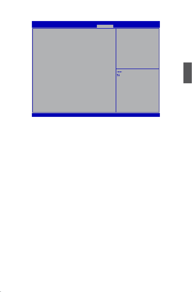
All Voltage Settings
CPU Core Voltage Mode [Standard Mode]
CPU Voltage Offset(1/10000 Volt) 0
CPU VTT (Uncore) Voltage [Default]
CPU PLL Voltage [1.80V]
CPU VccSA Voltage [Default]
DRAM Voltage [1.598V]
DIMM1 and DIMM3 DQ Vref(Data) Volt [64/128 VDIMM]
DIMM2 and DIMM4 DQ Vref(Data) Volt [64/128 VDIMM]
CougarPoint PCH Core Voltage [1.057V]
Aptio Setup Utility - Copyright (C) 2010 American Megatrends, Inc.
Quantum BIOS
CPU Core Power Voltage setting.
→ ←: Select Screen
↑ ↓: Select Item
Enter: Select
+/-: Change Opt.
F1: General Help
F2: Previous Values
F3: Optimized Defaults
F4: Save & Exit
ESC: Exit
Version 2.10.1208. Copyright (C) 2010 American Megatrends, Inc.
► CPU Core Voltage Mode
This item is used to select the CPU Core Power Voltage setting. Options are:[Standard Mode],
[Dynamic Mode], [Fixed Mode].
► CPU Voltage Offset(1/10000 Volt)
This item is used to set the CPU voltage offset. Press "+/-" keys to change the value by 40 per
step.
► CPU VTT (Uncore) Voltage
This item is used to select the CPU VTT (Uncore) voltage. [Default] means the voltage is
according to your CPU model. It can be 1.00V or 1.05V.
► CPU PLL Voltage
This item is used to set DRAM Voltage. The default voltage is 1.8V.
►CPU VccSA Voltage
This item is used to set the CPU Vcc system agent power voltage setting. The default voltage
for SandBridge CPU is 0.925V, for other CPU is 0.850V(Ivy etc...).
►DRAM Voltage
This item is used to set the DRAM voltage. The maximum available for adjustment is 2.501V.
The default voltage is 1.521V. Adjusting the voltage beyond the memories default voltage
could result in damage to memory controller.
►DIMM1 and DIMM3 DQ Vref(Data) Volt
This item is used to set the DIMMs Channel A DQ signals reference voltage. The default
option is: [64/128 VDIMM].
►DIMM2 and DIMM4 DQ Vref(Data) Volt
This item is used to set the DIMMs Channel B DQ signals reference voltage. The default
option is: [64/128 VDIMM].
►CougarPoint PCH Core Voltage
This item is used to set the CougarPoint PCH Core Voltage. The default option is: [1.057V].
3
45
Page 53

OC Gear
Backup Slot [Not Use It]
Aptio Setup Utility - Copyright (C) 2010 American Megatrends, Inc.
Quantum BIOS
You can backup your BIOS setting to slot
or restore your backup setting to BIOS or
erase your backup slot.
3
Version 2.10.1208. Copyright (C) 2010 American Megatrends, Inc.
→ ←: Select Screen
↑ ↓: Select Item
Enter: Select
+/-: Change Opt.
F1: General Help
F2: Previous Values
F3: Optimized Defaults
F4: Save & Exit
ESC: Exit
►Backup Slot
Through this item, you can backup your BIOS setting to slot or restore your backup setting to
BIOS or erase your backup slot.
Whe you select a slot for “Backup Slot”, the following items will appear:
►Current State of Backup Slot
This item is used to show the current state of the backup slot.
Backup Slot Description
►Save Backup
Here you can press [Enter] key choose save item to save your setting to current backup slot area.
►Load Backup
Here you can press [Enter] key choose load item for restore your current backup slot setting.
►Erase Backup Slot
Here you can press [Enter] key choose erase item to erase your current backup slotsetting.
46
Page 54

Hardware Monitor
CPU_FAN1 Control [Smart Fan]
CPU_FAN1 Speed : 2501 RPM
SYS_FAN1 Control [Smart Fan]
SYS_FAN1 Speed : N/A
SYS_FAN2 Control [Smart Fan]
SYS_FAN2 Speed : N/A
SYS_FAN3 Control [Smart Fan]
SYS_FAN3 Speed : N/A
SandyBridge CPU Temperature : +98 C
Sugarbay System Temperature : +29 C
CougarPoint PCH Temperature : +36 C
SandyBridge CPU PWM Temperature : +36 C
CPU Core Voltage : +1.06 V
CPU VTT(Uncore) Voltage : +1.06 V
DDR3 Memory Voltage : +1.60 V
CougarPonit PCH Core Voltage : +1.06 V
Battery 3V Voltage : +3.42 V
PSU Stand By 3.3V Rail : +3.30 V
PSU 3.3V Rail : +3.32 V
►CPU_FAN1 Control & SYS_FAN1/2/3 Control
These item are used to select the mode of CPU_FAN1& SYS_FAN1/2/3. The default option is:
[Smart Fan].
►CPU_FAN1 Speed & SYS_FAN1/2/3 Speed
This item is used to show the current speed of CPU_FAN1 & SYS_FAN1/2/3.
►SandyBridge CPU Temperature
This item is used to show the sandybridge CPU temperature.
►Sugarbay System Temperature
This item is used to show the sugarbay system temperature.
►CougarPoint PCH Temperature
This item is used to show the cougarpoint PCH temperature.
►SandyBridge CPU PWM Temperature
This item is used to show the sandybridge CPU PWM temperature.
►CPU Core Voltage
This item is used to show the voltage of CPU core.
►CPU VTT(Uncore) Voltage
This item is used to show the voltage of CPU VTT (Uncore).
►DDR3 Memory Voltage
This item is used to show the voltage of DDR3 memory.
►CougarPonit PCH Core Voltage
This item is used to show the voltage of cougarpoint PCH core.
►Battery 3V Voltage
This item is used to show the voltage of battery 3V.
►PSU Stand By 3.3V Rail
This item is used to show the voltage of PSU stand by 3.3V rail.
►PSU 3.3V Rail
This item is used to show the voltage of PSU 3.3V rail.
Aptio Setup Utility - Copyright (C) 2010 American Megatrends, Inc.
Version 2.10.1208. Copyright (C) 2010 American Megatrends, Inc.
Quantum BIOS
Smart Fan, Full Speed, By Duty-Cycle,
Stop Fan.
→ ←: Select Screen
↑ ↓: Select Item
Enter: Select
+/-: Change Opt.
F1: General Help
F2: Previous Values
F3: Optimized Defaults
F4: Save & Exit
ESC: Exit
3
47
Page 55

The utility CD that came with the motherboard contains useful
software and several utility drivers that enhance the mother-
board features.
This chapter includes the following information:
■ Utility CD content
■ Install driver and utility
■ AEGIS PANEL
■ FOX LOGO
■ FOX DMI
■ Browser Conguration Utility
Note : Because each module is independent, so the section
number will be reorganized and unique to each module, please
understand.
Page 56

Utility CD content
This motherboard comes with one DVD, after installing the Operating System, you can simply put
it into your DVD-ROM drive, and the main menu will be displayed on your PC screen to guide you
how to install.
1. Install Driver
Use these options to install all the drivers for your system. You should install the drivers in order,
and you need to restart your computer after all the drivers have been installed.
A. Intel Chipset Driver
B. Realtek HDA Audio Driver
C. Realtek LAN Driver
D. Intel RAID Driver*
E. Intel Management Engine Driver
F. USB 3.0 Driver
2. Software Utilities
Use these options to install additional software programs.
A. AEGIS PANEL
B. FOX LOGO
C. FOX DMI
D. Microsoft DirectX 9.0*
E. Adobe Acrobat Reader
F. Norton Internet Security
G. Browser Conguration Utility
*1 : This item will be displayed only when "SATA Mode" is set to [RAID Mode].
*2 : The item will appear in Windows XP operation system, but it will not show in Windows Vista
and Windows 7 operation system.
1
2
4
49
49
Page 57
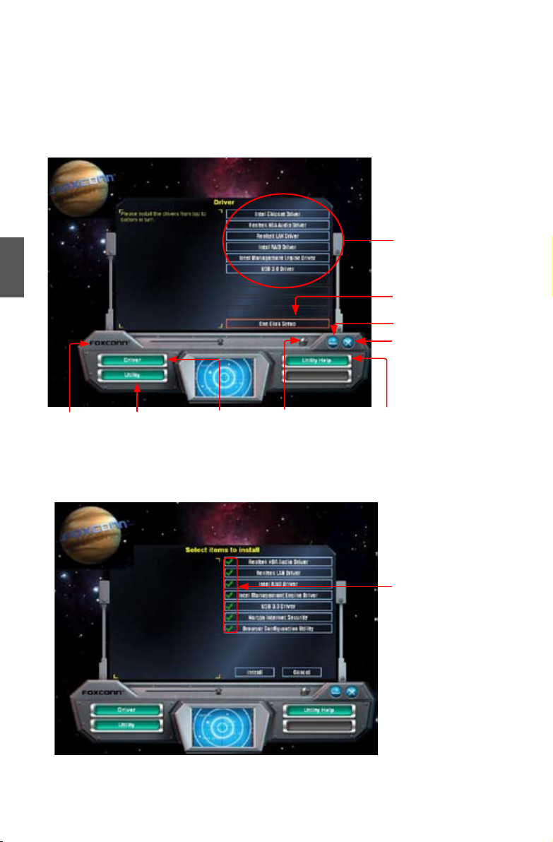
Install driver and utility
1. Install Driver
Use these options to install all the drivers for your system. You must click "Intel Chipset Driver"
to install it rst. After that, you can click “One Click Setup” and then choose the items you want to
install, or you can click on each individual driver to install it manually.
Manual Installation
Step by Step
4
Automatic Installation
by One Click
Drop to System Tray
Exit the program
Click to visit
Foxconn's
website
Select to Install
Utilities
Select to
Install Drivers
Browse CD
50
50
View the Utility
Help les
Choose the items you
want to Install
Page 58

2. Install Utility
Use these options to install additional software programs.
3. Utility Help
Click this button to view the utility(AEGIS PANEL,FOX LOGO, FOX DMI, etc.) help manual.
4
51
51
Page 59

AEGIS PANEL
Aegis Panel, is a Windows innovation tool which provides settings of OC gear, overclocking, fan
control and alarm function. It also displays system monitoring information such as fan speed,
temperature, voltage and CPU clock etc..
The powerful features are:
HW Monitor(Hardware Monitor Information)
Overclocking
OC Gear (Optional)
Conguration
Supported Operating Systems :
4
■ Windows XP (32-bit and 64-bit)
■ Windows Vista (32-bit and 64-bit)
Using AEGIS PANEL:
1. Main Panel
When AEGIS Panel is running, a main menu appears at the right hand side of the screen. This
menu will disappear if you remove the mouse from it a few seconds later. If you move the mouse
to touch the screen right where the menu stayed before, it will appear again.
52
52
HW Monitor
Overclocking
OC Gear (Optional)
Conguration
Close AEGIS PANEL
Page 60
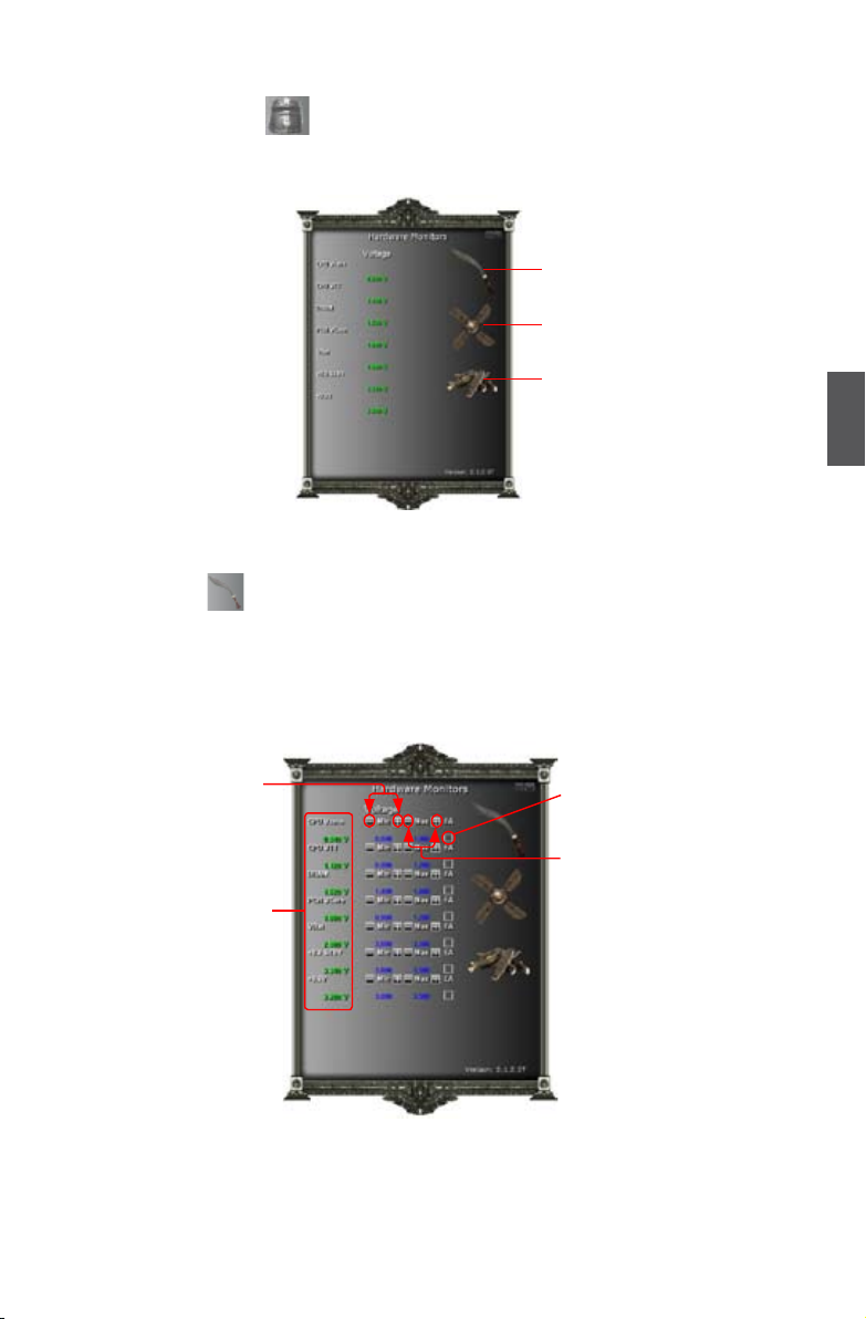
2. HW Monitor
Click on "HW Monitor" icon , its panel appears. By moving the mouse on the voltage icon,
it will display voltage information. Move the mouse on fan or temperature icon will show relative
information accordingly.
Voltage icon
Fan icon
Temperature icon
2.1 HW Monitor - Voltage
Click on voltage icon to get into the voltage setting menu. It allows you to set the low/high
limits of Vcore, CPU_VTT, +3.3V, +12V, VCC 1.1V, DRAM and Vbat voltages, and to enable the
alert function. If the current voltage value is lower than the low limit or higher than the high limit,
then a buzzer sounds.
4
Click these
buttons to set the
low limit voltage
Show current
voltages
Click it to enable
the alert function
Click these
buttons to set the
high limit voltage
53
53
Page 61
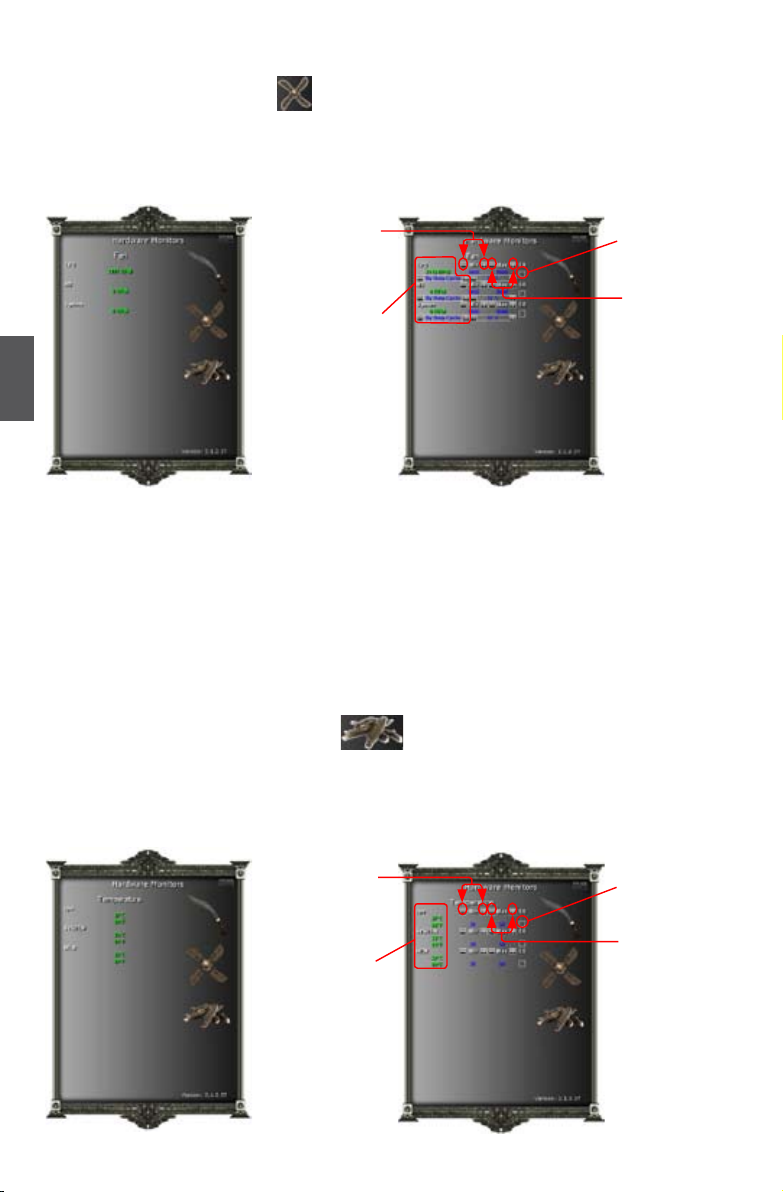
2.2 HW Monitor - Fan
Move the mouse on the fan icon , its menu appears. Click on the fan icon to get into the fan
setting menu. It allows you to set the low/high limits of the CPU, NB and System fan speeds, and
to enable the alert function. If the current fan value is lower than the low limit or higher than the
high limit, then a buzzer sounds.
Click these
buttons to set
the low limit
fan speed
Show current
fan speeds
Click it to enable the alert
function
Click these
buttons to set
the high limit
fan speed
4
Fan control has three operating modes:
By Full Speed:
Running at the full speed.
By Duty-Cycle:
The fan speed is controlled by setting the percentage to the fan duty (between 0% ~ 100%).
By Smart Fan:
Fan speed is controlled by the system automatically.
2.3 HW Monitor - Temperature
Move the mouse on the temperature icon , its menu appears. Click on the temperature
icon to get into the temperature setting menu. It allows you to set the low/high limits of CPU temperature, System temperature and NB temperature, and to enable the alert function. If the current
temperature value is lower than the low limit or higher than the high limit, then a buzzer sounds.
Click these buttons to set the
low limit CPU
temperature
Show current
temperatures
Click it to enable the
alert function
Click these
buttons to set
the high limit
CPU temperature
54
54
Page 62

3. Overclocking
Click "Overclocking" icon to enter the overclok setting menu. It allows you to adjust CPU
clock, and to change the voltages of CPU, chipset and memory. After you set the values, click
[Apply] button to apply it.
Click these buttons to
adjust the CPU clock
Click these buttons to adjust
the CPU voltages
Click these buttons
to adjust the Chipset
voltage
Apply the changes
Click these buttons to adjust
the memory voltage
4. Conguration
4
Click "Conguration" icon to congure Aegis function. You can enable or disable the
launch of "Aegis Panel Ex" on startup. If enabled, the Aegis Panel will be automatically activated
when the Windows operating system is running.
55
55
Page 63

FOX LOGO
FOX LOGO is a simple and useful utility to backup, change and delete the boot time
Logo. The boot Logo is the image that appears on screen during POST (Power-On
Self-Test).
You can prepare a JPG image (1024x768) le, then use FOX LOGO to open it and
change the boot time Logo. Boot time Logo will be displayed if you enable the BIOS
"Quiet Boot" setting in "Boot" menu.
Supporting Operating Systems :
■ Windows 2000
4
■ Windows XP (32-bit and 64-bit)
■ Windows 2003 (32-bit and 64-bit)
■ Windows Vista (32-bit and 64-bit)
■ Windows 7 (32-bit and 64-bit)
Using FOX LOGO:
Main Page
Main screen
Backup
Change
Delete
I
N
N
G
R
A
!
W
Exit
Minimize
Website
About
When you change Logo or delete current Logo, the system will ash BIOS le auto-
matically. During this time, please DO NOT shut down the application and the system,
or the motherboard will be damaged seriously.
56
56
Page 64

FOX DMI
FOX DMI is a full Desktop Management Interface viewer, and it provides three DMI data
formats : Report, Data Fields and Memory Dump.
With DMI information, system maker can easily analyze and troubleshoot your mother-
board if there is any problem occurred.
Supporting Operating Systems :
■ Windows 2000
■ Windows XP (32-bit and 64-bit)
■ Windows 2003 (32-bit and 64-bit)
■ Windows Vista (32-bit and 64-bit)
■ Windows 7 (32-bit and 64-bit)
Using FOX DMI:
Please operate this utility as the comments shows.
4
Click here to select
the type you want
to view.
Click here to select
the DMI Data format
you need
57
57
Page 65

Browser Conguration Utility
Browser Conguration Utility is a browser search engine of Yahoo. We provide it to you for
various choice.
Supporting Operating Systems :
■ Windows XP (32-bit and 64-bit)
■ Windows Vista (32-bit and 64-bit)
■ Windows 7 (32-bit and 64-bit)
Using Browser Conguration Utility:
1. After installation, it will appear in the search menu of browser. You can use it directly.
2. If you have installed another search engine, the Browser Conguration Utility will send out a
dialog to ask “Do you want to change your browser search engine to Yahoo?” If you want to
4
use Yahoo engine as the default. Select “Yes” and click “OK”.
Then you will see a “END USER LICENSE AGREEMENT”. Read it and select “I agree” to
change your default search engine.
3. Browser Conguration Utility supports online games. Double click the game icon on your
desktop to enjoy it.
58
58
Page 66

This chapter will cover two topics :
■ Installing a new Windows XP (Vista) in a brand new RAID
system.
■ Existing Windows XP (Vista) system with new RAID built as
data storage.
It includes the following information :
■ RAID Conguration Introduction
■ Intel® Matrix Storage Manager
■ Create a RAID Driver Diskette
■ BIOS Conguration
■ Create RAID in BIOS
■ Install a New Windows XP
■ Existing Windows XP with RAID built as data storage
The RAID BIOS Setup pictures shown in this chapter are for
reference only, please refer to the practical screen.
Page 67

Installing a new Windows XP (Vista) in a brand new RAID
system.
1. Follow 5-1 to create a RAID driver diskette.
(Windows Vista has in-box driver by its own and can skip this step).
2. Follow 5-2 to set BIOS setting "SATA Mode" to RAID or AHCI.
3. Follow 5-3 to create RAID in BIOS.
4. Follow 5-4 to Install Windows Operating System.
What kinds of hardware and software you need here :
1. A oppy drive.
2. A CD-ROM drive.
3. Several SATA hard disks.
4. A RAID driver diskette.
5. A motherboard driver CD.
5
6. Windows XP or Vista Install CD.
Existing Windows XP (Vista) system with new RAID built as
data storage.
Follow 5-5 to go through the processes to build a new RAID data storage in your existing Windows XP system, it includes :
1. Copy RAID driver setup program to your hard disk. (Vista can skip)
2. Follow 5-2 to set BIOS setting "SATA Mode" to RAID or AHCI.
3. Follow 5-3 to create RAID in BIOS.
4. Run setup program to install Intel® Matrix Storage Manager driver into your current
Windows XP system. (Vista can skip this step)
5. Format new RAID partitions.
What kinds of hardware and software you need here :
1. A CD-ROM drive.
2. Several SATA hard disks.
3. A motherboard driver CD.
60
Page 68

RAID Conguration Introduction
RAID (Redundant Array of Independent Disks) is a method for computer data storage
schemes that divide and/or replicate data among multiple hard drives. RAID can
be designed to provide increased data reliability (fault tolerance) or increased I/O
(input/output) performance, or both. The motherboard comes with the Intel® PCH. The
following RAID congurations are provided for users.
There are three major key concepts in RAID:
1. Mirroring : The copying of data to more than one disk;
2. Striping : The splitting of data across more than one disk;
3. Error correction : Where redundant data is stored to allow problems to be detected
and possibly xed (known as fault tolerance).
Different RAID levels use one or more of these techniques, depending on the system
requirements. The main aims of using RAID are to improve reliability, important for
protecting information that is critical to a business, for example a database of customer
orders; or where speed is important, for example a system that delivers video on
demand TV programs to many viewers.
The conguration affects reliability and performance in different ways. The problem
with using more disks is that it is more likely that one will go wrong, but by using
error checking the total system can be made more reliable by being able to survive
and repair the failure. Basic mirroring can speed up reading data as a system can
read different data from both the disks, but it may be slow for writing if it insists that
both disks must conrm that the data is correctly written. Striping is often used for
performance, where it allows sequences of data to be read off multiple disks at the
same time. Error checking typically will slow the system down as data needs to be
read from several places and compared. The design of RAID systems is therefore a
compromise and understanding the requirements of a system is important. Modern
disk arrays typically provide the facility to select the appropriate RAID conguration.
RAID is often used in high availability systems, where it is important that the system
keeps running as much of the time as possible.
5
61
Page 69

RAID 0 (Stripe)
RAID 0 reads and writes sectors of data interleaved among multiple drives. If any disk
member fails, it affects the entire array. The disk array data capacity is equal to the
number of drive members times the capacity of the smallest member. The striping
block size can be set from 4KB to 128KB. RAID 0 does not support fault tolerance.
RAID 1 (Mirror)
RAID 1 writes duplicate data onto a pair of drives and reads both sets of data in
parallel. If one of the mirrored drives suffers a mechanical failure or does not respond,
the remaining drive will continue to function. Due to redundancy, the drive capacity of
the array is the capacity of the smallest drive. Under a RAID 1 setup, an extra drive
called the “spare drive” can be attached. Such a drive will be activated to replace a
failed drive that is part of a mirrored array. Due to the fault tolerance, if any RAID 1
drive fails, data access will not be affected as long as there are other working drives in
the array.
5
RAID 5 (Parity)
RAID 5 provides data striping at the byte level and also stripes error correction
information. This results in excellent performance and good fault tolerance. Level 5 is
one of the most popular implementations of RAID.
RAID 10 (0+1)
RAID 10 is a combination of striping and mirroring. This conguration provides optimal
speed and reliability, but you need four SATA hard disks.
Recovery
This level copies data between a master and a recovery disk, so the capacity of the
array is equal to the capacity of the smaller drive. It’s no need to set the strip size for
Recovery, but you must select a sync mode to update the volume.
Comparison Table :
Solution Hard Disks No. Capacity Performance Reliability Application
RAID0 >=2 All Highest Dangerous Look for speed
RAID1 2 50% Read faster Excellent 100% Data backup
RAID5 >=3 N-1 Read faster
RAID10 >=4
Recovery 2 Smaller Read faster Excellent 100% Data backup
(Even number)
Smallest
*2
Write slower
High Excellent Unlimited budget
Good Limited budget
62
Page 70

Intel® Matrix Storage Manager
The Intel® Matrix Storage Manager technology supports RAID 0 ,RAID 1, RAID 5, and
RAID 10 (0+1) functions. It allows you to get high performance with fault tolerance, big
capacity, or data safety provided by different RAID functions.
In this section, we will use four SATA hard disks as an example to guide you how to
congure your RAID system. There are two 149.0GBs and two 74.5GBs. A creation of
second volume will also be well described.
In each screen, there is also a message bar about each key’s function, such as <Tab>,
<Enter>, <Del>...etc. it is to help making your selection easier.
The topic will be introduced :
Installing a new Windows XP in a brand new RAID system.
N
O
I
T
U
A
C
!
Before installing the SATA hard disks, make sure to turn off the computer
and unplug the power cord from the power outlet to prevent damage to the
hardware.
5
Steps to Install Serial ATA Hard Disks :
1. Install SATA hard disks into the drive bays.
2. Connect one end of the SATA cable to motherboard’s SATA connector, and the
other end to SATA hard disk.
3. Connect SATA power cable to the power connector of SATA hard disk.
I
N
N
G
R
A
!
W
■ Both AHCI and RAID modes need to install Intel® Matrix Storage Manager
driver.
■ Set SATA mode in BIOS to AHCI, you can skip RAID BIOS creation steps,
but the software driver installation of Intel® Matrix Storage Manager shall
follow the same rule as described for RAID.
63
Page 71
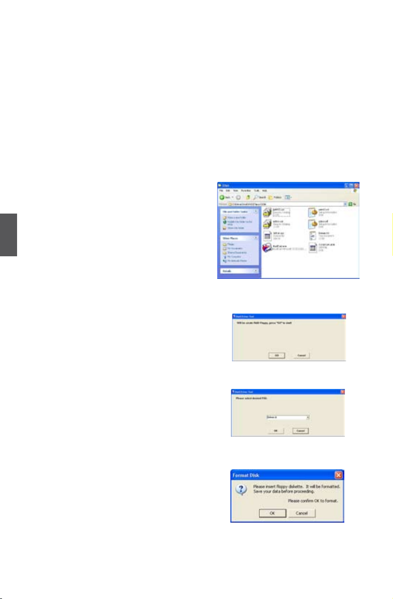
5-1 Create a RAID driver diskette
If you want to install a brand new Windows XP on a AHCI or RAID system, you need to
congure the SATA Mode in BIOS to either AHCI or RAID rst. You also need to create
a RAID driver diskette for use in installing your Windows XP system.
Windows Vista has native RAID driver in itself, you can skip these steps.
1. Find a PC, put a diskette into its oppy
drive A:, this diskette will be formatted later.
Put the driver CD into DVD-ROM drive.
2. Depending on which platform your system
is, normally, it is a 32-bit XP system. Use
Windows explorer, and go to CD:\Driver\
5
Intel\RAID\Floppy\32bit, click on Raid-
Tool icon to start the creation.
3. Click "GO" to start.
4. Select the desired destination FDD drive.
It can be the default drive A: or any USB
FDD. Click "OK" to continue.
5. Insert a diskette, click "OK" to continue.
64
Page 72

6. You can input a volume label for this diskette, click
on "Start" to format.
7.Cl i c k on "O K " to go th r o u g h this warning
message.
8. Format nished. Click "OK" to continue copying of
RAID driver into this diskette.
9. Check if the diskette contains the driver les.
Later, when in the process of installing Windows XP in your RAID system, it will ask you
to use this oppy diskette to provide driver for additional specic devices, for example,
a RAID device.
10. Install Serial ATA Hard Disks :
10-1. Shut down your computer.
10-2. Install SATA hard disks into the drive bays, connect all power and SATA
cables.
5
65
Page 73
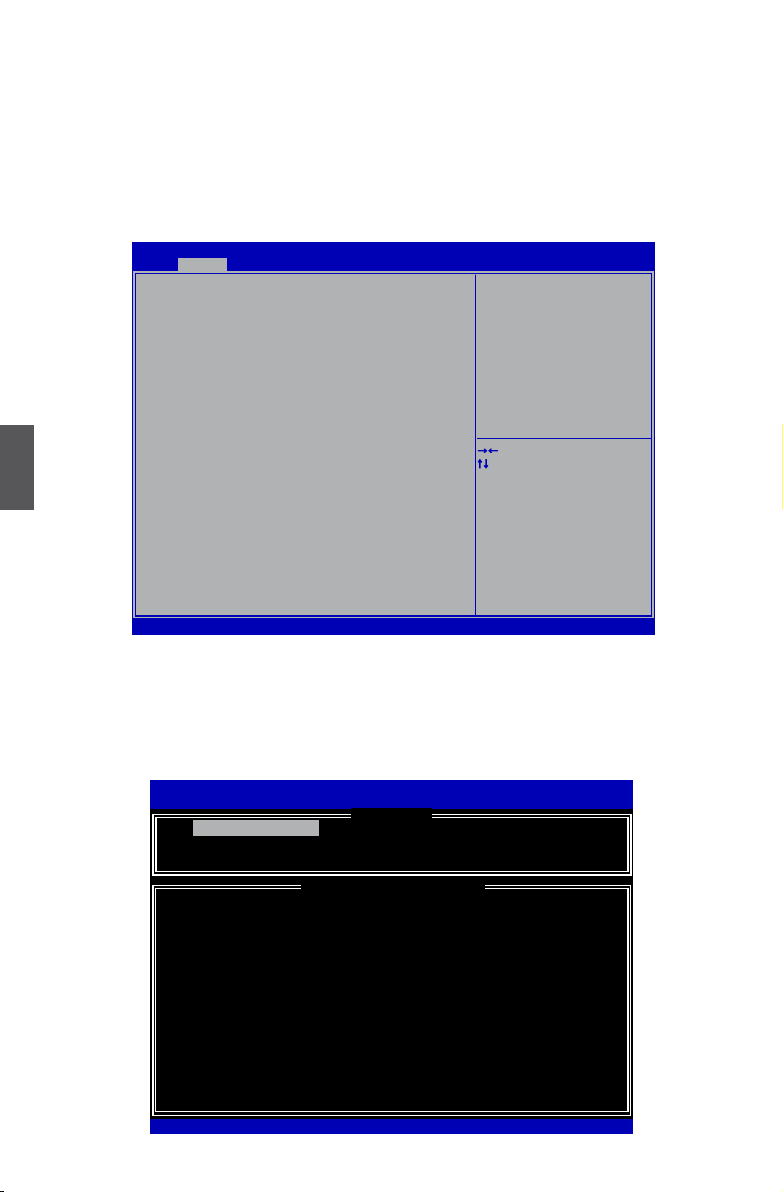
5-2 BIOS Conguration
1. Enter the BIOS setup by pressing <DEL> key during the POST(Power On Self Test).
2. Use the arrow right/left keys to select the “Advanced” menu, then use the arrow
up/down keys to select the “SATA Conguration” item and press <Enter> to go to the
conguration items.
3. Press <Enter> to select and set the “SATA Mode” option to [RAID Mode].
4. Press <F4> to save the setting then PC will reboot itself.
Advanced
SATA Configuration
SATA Mode [RAID Mode]
SATA Port 0 Not Present
Hot Plug [Disabled]
SATA Port 1 Not Present
Hot Plug [Disabled]
SATA Port 2 Not Present
Hot Plug [Disabled]
SATA Port 3 Not Present
5
Hot Plug [Disabled]
SATA Port 4 Not Present
Hot Plug [Disabled]
SATA Port 5 Not Present
Hot Plug [Disabled]
Aptio Setup Utility - Copyright (C) 2010 American Megatrends, Inc.
(1) IDE Mode. (2) AHCI Mode
(3) RAID Mode.
→ ←: Select Screen
↑ ↓: Select Item
Enter: Select
+/-: Change Opt.
F1: General Help
F2: Previous Values
F3: Optimized Defaults
F4: Save & Exit
ESC: Exit
Version 2.10.1208. Copyright (C) 2010 American Megatrends, Inc.
5-3 Create RAID in BIOS
Enter RAID BIOS Setup
When BIOS is restarted, it will display a message asking you to press <Ctrl>+<I> keys
simultaneously to enter the main menu of Intel® Matrix Storage Manager Option ROM
Utility. Press the <Ctrl>+<I> to enter Conguration Utility.
Intel(R) Matrix Storage Manager option ROM v5.0.0.1011 ICH9R w6AID5
Copyright(C) 2003-04 Intel Corporation All Rights Reserved.
1. Create RAID Volume 3. Reset Disks to Non-RAID
5. Exit
RAID Volume :
None Dened.
Physical Disks:
Port Drive Model Serial # Size Type/Status(Vol ID)
0 Hitachi HDS72161 PVF904Z21G2JZM 149.0GB
1
2
3
[↑↓]-Select [ESC]-Exit [ENTER]-Select Menu
Intel(R) Rapid Storage Technology - Option ROM - 10.0.0.1032
Copyright(C) 2003-10 Intel Corporation. All Rights Reserved.
1. Create RAID Volume
2. Delete RAID Volume 4. Recover Volume Options
ST380811AS
SAMSUNG HD161HJ
ST380815AS
[ MAIN MENU ]
[ DISK/VOLUME INFORMATION ]
5PS1TAGW 74.5GB Non-RAID Disk
S0V3J9APA30524 149.0GB Non-RAID Disk
5RW1CA37
74.5GB Non-RAID Disk
Non-RAID Disk
66
Page 74

Create RAID Volume
Create RAID 0 (1st Volume)
1. Select “1. Create RAID Volume” from the menu and press <Enter>.
The menu appears :
Intel(R) Matrix Storage Manager option ROM v5.0.0.1011 ICH9R wRAID5
Copyright(C) 2003-04 Intel Corporation All Rights Reserved.
[↑↓]-Change [TAB]-Next [ESC]-Previous Menu [ENTER]-Select
Intel(R) Rapid Storage Technology - Option ROM - 10.0.0.1032
Copyright(C) 2003-10 Intel Corporation. All Rights Reserved.
Enter a unique volume name that has no special characters and is
[ CREATE VOLUME MENU ]
Volume0
Name:
Disks:
Strip Size:
Capacity:
Sync:
16 characters or less.
Volume0
RAID0(Stripe)
Select Disks
128KB
0.0 GB
N/A
Create Volume
[ HELP ]
RAID Level:
2. In "Name" item, you can input a device name for the RAID0 system and press <Enter>
to apply it. Here, we name it as TryRAID0 to replace the default Volume0.
3. In “RAID Level” item, you can use Up or Down arrow key to make a selection. Select
RAID0 (Stripe) and press <Enter>.
Intel(R) Matrix Storage Manager option ROM v5.0.0.1011 ICH9R wRAID5
Copyright(C) 2003-04 Intel Corporation All Rights Reserved.
Intel(R) Rapid Storage Technology - Option ROM - 10.0.0.1032
Copyright(C) 2003-10 Intel Corporation. All Rights Reserved.
[ CREATE VOLUME MENU ]
Name:
Disks:
Strip Size:
Capacity:
Sync:
TryRAID0
RAID0(Stripe)
RAID0(Stripe)
Select Disks
128KB
0.0 GB
N/A
Create Volume
RAID Level:
5
[ HELP ]
RAID 0: Stripes data (performance).
[↑↓]-Change [TAB]-Next [ESC]-Previous Menu [ENTER]-Select
67
Page 75

4. It then goes to “Disks” item. Press <Enter> to display the hard disks list for this RAID0
system.
Intel(R) Matrix Storage Manager option ROM v5.0.0.1011 ICH9R wRAID5
Copyright(C) 2003-04 Intel Corporation All Rights Reserved.
Intel(R) Rapid Storage Technology - Option ROM - 10.0.0.1032
Copyright(C) 2003-10 Intel Corporation. All Rights Reserved.
Port Drive Model Serial # Size Status
0 Hitachi HDS721616PLA PVF904Z21G2JZM 149.0GB Non-RAID Disk
0 Hitachi HDS721616PLA PVF904Z21G2JZM 149.0GB Non-RAID Disk
ST380811AS
1
SAMSUNG HD161HJ
2
ST380815AS
3
[ CREATE VOLUME MENU ]
Name:
RAID Level:
Select 2 to 6 disks to use in creating the volume.
TryRAID0
RAID0(Stripe)
[ SELECT DISKS ]
5PS1TAGW 74.5GB Non-RAID Disk
S0V3J9APA30524 149.0GB Non-RAID Disk
5RW1CA37
74.5GB Non-RAID Disk
5
[↑↓]-Prev/Next [SPACE]-SelectDisk [ENTER]-Done
[↑↓]-Change [TAB]-Next [ESC]-Previous Menu [ENTER]-Select
5. From the hard drive list, use Up or Down arrow key to reach the hard disks you want
to combine them as RAID0, then press <Space> key to select them. A triangle sign
will appear to indicate the drive selected. Here, we select two 149.0GB hard disks as
an example. Press <Enter> key to nish the selection.
Intel(R) Matrix Storage Manager option ROM v5.0.0.1011 ICH9R wRAID5
Copyright(C) 2003-04 Intel Corporation All Rights Reserved.
Intel(R) Rapid Storage Technology - Option ROM - 10.0.0.1032
Copyright(C) 2003-10 Intel Corporation. All Rights Reserved.
Port Drive Model Serial # Size Status
►0 Hitachi HDS721616PLA PVF904Z21G2JZM 149.0GB Non-RAID Disk
ST380811AS
1
►2
SAMSUNG HD161HJ
2 SAMSUNG HD161HJ S0V3J9APA30524 149.0GB Non-RAID Disk
ST380815AS
3
[↑↓]-Prev/Next [SPACE]-SelectDisk [ENTER]-Done
[ CREATE VOLUME MENU ]
Name:
RAID Level:
Select 2 to 6 disks to use in creating the volume.
TryRAID0
RAID0(Stripe)
[ SELECT DISKS ]
5PS1TAGW 74.5GB Non-RAID Disk
S0V3J9APA30524 149.0GB Non-RAID Disk
5RW1CA37
74.5GB Non-RAID Disk
[↑↓]-Change [TAB]-Next [ESC]-Previous Menu [ENTER]-Select
68
Page 76

6. It is now entering “Strip Size” menu. Use Up or Down arrow key to select the desired
strip size. The available values range from 4KB to 128KB. The strip value should be
selected based on different applications. Some suggested choices are :
16K - Best for sequential transfer.
64K - Good general purpose strip size.
128K - Best performance for most desktops and workstations .
The default value is 128K for RAID0. Press <Enter>.
Intel(R) Matrix Storage Manager option ROM v5.0.0.1011 ICH9R wRAID5
Copyright(C) 2003-04 Intel Corporation All Rights Reserved.
RAID0 - 128KB
RAID10 - 64KB
RAID5 - 64KB
[↑↓]-Change [TAB]-Next [ESC]-Previous Menu [ENTER]-Select
Intel(R) Rapid Storage Technology - Option ROM - 10.0.0.1032
Copyright(C) 2003-10 Intel Corporation. All Rights Reserved.
[ CREATE VOLUME MENU ]
Name:
RAID Level:
TryRAID0
RAID0(Stripe)
Disks:
Select Disks
Strip Size:
128KB
Capacity:
128KB
298.1 GB
Sync:
N/A
Create Volume
[ HELP ]
The following are typical values:
7. In “Capacity” item, the default value indicates the maximum capacity using the selected
disks. As we want to introduce how to create two disk volumes (like logical devices C:
and D:) in a RAID0 system, so we only key in 150GB here to build the rst volume.
Later, we will also describe how the second volume is generated. Input 150GB, and
press <Enter>.
Intel(R) Matrix Storage Manager option ROM v5.0.0.1011 ICH9R wRAID5
Copyright(C) 2003-04 Intel Corporation All Rights Reserved.
Intel(R) Rapid Storage Technology - Option ROM - 10.0.0.1032
Copyright(C) 2003-10 Intel Corporation. All Rights Reserved.
[ CREATE VOLUME MENU ]
Name:
Disks:
Strip Size:
Capacity:
TryRAID0
RAID0(Stripe)
Select Disks
128KB
465.8 GB
150
Create Volume
RAID Level:
5
[ HELP ]
The default value indicates the maximum capacity using the selected
disks. Entering a lower capacity allows you to create a second
[↑↓]-Change [TAB]-Next [ESC]-Previous Menu [ENTER]-Select
volume on these disks
69
Page 77

8. In “Create Volume” item, press <Enter>.
Intel(R) Matrix Storage Manager option ROM v5.0.0.1011 ICH9R wRAID5
Copyright(C) 2003-04 Intel Corporation All Rights Reserved.
Intel(R) Rapid Storage Technology - Option ROM - 10.0.0.1032
Copyright(C) 2003-10 Intel Corporation. All Rights Reserved.
[ CREATE VOLUME MENU ]
TryRAID0
Name:
Disks:
Strip Size:
Capacity:
Sync:
RAID0(Stripe)
Select Disks
128KB
150 GB
N/A
Create Volume
Create Volume
[ HELP ]
RAID Level:
Press ENTER to create the specified volume.
5
[↑↓]-Change [TAB]-Next [ESC]-Previous Menu [ENTER]-Select
A warning message will appear :
WARNING: ALL DATA ON SELECTED DISKS WILL BE LOST.
Are you sure you want to create this volume ? (Y/N) :
9. Press <Y> to create the volume and return to the main menu, a 150GB RAID0 system
is normally congured.
Intel(R) Matrix Storage Manager option ROM v5.0.0.1011 ICH9R wRAID5
Copyright(C) 2003-04 Intel Corporation All Rights Reserved.
1. Create RAID Volume 3. Reset Disks to Non-RAID
5. Exit
RAID Volume :
ID Name Level Stripe Size Status Bootable
0 TryRAID0 RAID0(Stripe) 128KB 150.0GB
Physical Disks:
Port Drive Model Serial # Size Type/Status(Vol ID)
0 Hitachi HDS72161 PVF904Z21G2JZM 149.0GB
1
2
3
Intel(R) Rapid Storage Technology - Option ROM - 10.0.0.1032
Copyright(C) 2003-10 Intel Corporation. All Rights Reserved.
1. Create RAID Volume
2. Delete RAID Volume 4. Recover Volume Options
ST380811AS
SAMSUNG HD161HJ
ST380815AS
[ MAIN MENU ]
[ DISK/VOLUME INFORMATION ]
Normal Yes
5PS1TAGW 74.5GB Non-RAID Disk
S0V3J9APA30524 149.0GB Member Disk(0)
5RW1CA37
74.5GB Non-RAID Disk
Member Disk(0)
[↑↓]-Select [ESC]-Exit [ENTER]-Select Menu
70
Page 78

Create RAID0 (2nd Volume)
1. Select “1. Create RAID Volume” from the menu and press <Enter>.
The menu appears :
Intel(R) Matrix Storage Manager option ROM v5.0.0.1011 ICH9R wRAID5
Copyright(C) 2003-04 Intel Corporation All Rights Reserved.
[↑↓]-Change [TAB]-Next [ESC]-Previous Menu [ENTER]-Select
Intel(R) Rapid Storage Technology - Option ROM - 10.0.0.1032
Copyright(C) 2003-10 Intel Corporation. All Rights Reserved.
Enter a unique volume name that has no special characters and is
[ CREATE VOLUME MENU ]
Name:
Volume0
RAID Level:
Strip Size:
Volume0
RAID0(Stripe)
Disks:
Select Disks
128KB
Capacity:
0.0 GB
Sync:
N/A
Create Volume
16 characters or less.
[ HELP ]
2. In "Name" item, we name it as TryRAID0-1 for second volume.
3. In “RAID Level” item, you can use Up or Down arrow key to make a selection, only
RAID0, 1 can be selected. Select RAID0 (Stripe) and press <Enter>.
(Note : You also can try to select RAID1 for the second volume as an experiment here)
Intel(R) Matrix Storage Manager option ROM v5.0.0.1011 ICH9R wRAID5
Copyright(C) 2003-04 Intel Corporation All Rights Reserved.
Intel(R) Rapid Storage Technology - Option ROM - 10.0.0.1032
Copyright(C) 2003-10 Intel Corporation. All Rights Reserved.
[ CREATE VOLUME MENU ]
Name:
Disks:
Strip Size:
Capacity:
Sync:
TryRAID0-1
RAID0(Stripe)
RAID0(Stripe)
Select Disks
128KB
0.0 GB
N/A
Create Volume
RAID Level:
5
[ HELP ]
RAID 0: Stripes data (performance).
[↑↓]-Change [TAB]-Next [ESC]-Previous Menu [ENTER]-Select
71
Page 79

4. It then goes to “Disks” item. Press <Enter> to display the hard disks list for this RAID0
second volume system.
Intel(R) Matrix Storage Manager option ROM v5.0.0.1011 ICH9R wRAID5
Copyright(C) 2003-04 Intel Corporation All Rights Reserved.
Intel(R) Rapid Storage Technology - Option ROM - 10.0.0.1032
Copyright(C) 2003-10 Intel Corporation. All Rights Reserved.
Port Drive Model Serial # Size Status
0 Hitachi HDS721616PLA PVF904Z21G2JZM 149.0GB Member Disk
0 Hitachi HDS721616PLA PVF904Z21G2JZM 149.0GB Non-RAID Disk
ST380811AS
1
SAMSUNG HD161HJ
2
ST380815AS
3
[↑↓]-Prev/Next [SPACE]-SelectDisk [ENTER]-Done
[ CREATE VOLUME MENU ]
Name:
RAID Level:
Select 2 to 6 disks to use in creating the volume.
TryRAID0-1
RAID0(Stripe)
[ SELECT DISKS ]
5PS1TAGW 74.5GB Non-RAID Disk
S0V3J9APA30524 149.0GB Member Disk
5RW1CA37
74.5GB Non-RAID Disk
5
[↑↓]-Change [TAB]-Next [ESC]-Previous Menu [ENTER]-Select
5. From the hard disk list, select the previously congured RAID0 hard disks, and press
<Space> key to select them. Two signs will appear to indicate the selections. Press
<Enter> to continue.
Intel(R) Matrix Storage Manager option ROM v5.0.0.1011 ICH9R wRAID5
Copyright(C) 2003-04 Intel Corporation All Rights Reserved.
Intel(R) Rapid Storage Technology - Option ROM - 10.0.0.1032
Copyright(C) 2003-10 Intel Corporation. All Rights Reserved.
Port Drive Model Serial # Size Status
0 Hitachi HDS721616PLA PVF904Z21G2JZM 149.0GB Member Disk
►0 Hitachi HDS721616PLA PVF904Z21G2JZM 149.0GB Member Disk
ST380811AS
1
►2
SAMSUNG HD161HJ
ST380815AS
3
[ CREATE VOLUME MENU ]
Name:
RAID Level:
TryRAID0-1
RAID0(Stripe)
[ SELECT DISKS ]
5PS1TAGW 74.5GB Non-RAID Disk
S0V3J9APA30524 149.0GB Member Disk
5RW1CA37
74.5GB Non-RAID Disk
Select 2 to 6 disks to use in creating the volume.
[↑↓]-Prev/Next [SPACE]-SelectDisk [ENTER]-Done
[↑↓]-Change [TAB]-Next [ESC]-Previous Menu [ENTER]-Select
72
Page 80

6. It goes to “Strip Size” menu directly. Capacity automatically displays 148.1GB, and
at this time, you can not input any value in capacity as there is no additional volume
available.
The available values of Strip Size range from 4KB to 128KB. The strip value should be
selected based on different applications. Some suggested choices are :
16K - Best for sequential transfer.
64K - Good general purpose strip size.
128K - Best performance for most desktops and workstations .
The default value is 128K. Press <Enter>.
Intel(R) Matrix Storage Manager option ROM v5.0.0.1011 ICH9R wRAID5
Copyright(C) 2003-04 Intel Corporation All Rights Reserved.
RAID0 - 128KB
RAID10 - 64KB
RAID5 - 64KB
[↑↓]-Change [TAB]-Next [ESC]-Previous Menu [ENTER]-Select
Intel(R) Rapid Storage Technology - Option ROM - 10.0.0.1032
Copyright(C) 2003-10 Intel Corporation. All Rights Reserved.
[ CREATE VOLUME MENU ]
Name:
RAID Level:
TryRAID0-1
RAID0(Stripe)
Disks:
Select Disks
Strip Size:
128KB
128KB
Capacity:
148.1 GB
Sync:
N/A
Create Volume
[ HELP ]
The following are typical values:
7. Select “Create Volume” and press <Enter>.
Intel(R) Matrix Storage Manager option ROM v5.0.0.1011 ICH9R wRAID5
Copyright(C) 2003-04 Intel Corporation All Rights Reserved.
Intel(R) Rapid Storage Technology - Option ROM - 10.0.0.1032
Copyright(C) 2003-10 Intel Corporation. All Rights Reserved.
[ CREATE VOLUME MENU ]
TryRAID0-1
Name:
Disks:
Strip Size:
Capacity:
Sync:
RAID0(Stripe)
Select Disks
128KB
148.1 GB
N/A
Create Volume
Create Volume
RAID Level:
5
[ HELP ]
Press ENTER to create the specified volume.
[↑↓]-Change [TAB]-Next [ESC]-Previous Menu [ENTER]-Select
73
Page 81

A message will appear :
Are you sure you want to create this volume ? (Y/N) :
Press <Y> to create the volume and return to the main menu. Two RAID0 volumes
were congured.
Intel(R) Matrix Storage Manager option ROM v5.0.0.1011 ICH9R wRAID5
Copyright(C) 2003-04 Intel Corporation All Rights Reserved.
1. Create RAID Volume 3. Reset Disks to Non-RAID
5. Exit
RAID Volume :
5
ID Name Level Stripe Size Status Bootable
0 TryRAID0 RAID0(Stripe) 128KB 150.0GB
1 TryRAID0-1 RAID0(Stripe) 128KB 148.1GB
Physical Disks:
Port Drive Model Serial # Size Type/Status(Vol ID)
0 Hitachi HDS72161 PVF904Z21G2JZM 149.0GB
1
2
3
[↑↓]-Select [ESC]-Exit [ENTER]-Select Menu
Intel(R) Rapid Storage Technology - Option ROM - 10.0.0.1032
Copyright(C) 2003-10 Intel Corporation. All Rights Reserved.
1. Create RAID Volume
2. Delete RAID Volume 4. Recover Volume Options
ST380811AS
SAMSUNG HD161HJ
ST380815AS
[ MAIN MENU ]
[ DISK/VOLUME INFORMATION ]
Normal Yes
Normal Yes
5PS1TAGW 74.5GB Non-RAID Disk
S0V3J9APA30524 149.0GB Member Disk(0,1)
5RW1CA37
74.5GB Non-RAID Disk
Member Disk(0,1)
74
Page 82

Create RAID 1
1. Select “1.Create RAID Volume” from the main menu and press <Enter>.
2. In "Name" item, you can input a device name for the RAID1 system and press
<Enter> to apply it. Here, we name it as TryRAID1 to replace the default Volume0.
Intel(R) Matrix Storage Manager option ROM v5.0.0.1011 ICH9R wRAID5
Copyright(C) 2003-04 Intel Corporation All Rights Reserved.
[↑↓]-Change [TAB]-Next [ESC]-Previous Menu [ENTER]-Select
Intel(R) Rapid Storage Technology - Option ROM - 10.0.0.1032
Copyright(C) 2003-10 Intel Corporation. All Rights Reserved.
Enter a unique volume name that has no special characters and is
[ CREATE VOLUME MENU ]
Name:
Volume0
RAID Level:
Strip Size:
TryRAID1
RAID0(Stripe)
Disks:
Select Disks
128KB
Capacity:
0.0 GB
Sync:
N/A
Create Volume
16 characters or less.
[ HELP ]
3. In “RAID Level” item, you can use Up or Down arrow key to make a selection.
Select RAID1 (Mirror) and press <Enter>.
Intel(R) Matrix Storage Manager option ROM v5.0.0.1011 ICH9R wRAID5
Copyright(C) 2003-04 Intel Corporation All Rights Reserved.
Intel(R) Rapid Storage Technology - Option ROM - 10.0.0.1032
Copyright(C) 2003-10 Intel Corporation. All Rights Reserved.
[ CREATE VOLUME MENU ]
Name:
Disks:
Strip Size:
Capacity:
Sync:
TryRAID1
RAID1(Mirror)
RAID1(Mirror)
Select Disks
N/A
0.0 GB
N/A
Create Volume
RAID Level:
5
[ HELP ]
RAID1: Mirrors data (redundancy).
[↑↓]-Change [TAB]-Next [ESC]-Previous Menu [ENTER]-Select
75
Page 83

4. It then goes to “Disks” item. Press <Enter> to dispaly the hard disks list for this
RAID1 system.
Intel(R) Matrix Storage Manager option ROM v5.0.0.1011 ICH9R wRAID5
Copyright(C) 2003-04 Intel Corporation All Rights Reserved.
5
[↑↓]-Change [TAB]-Next [ESC]-Previous Menu [ENTER]-Select
Intel(R) Rapid Storage Technology - Option ROM - 10.0.0.1032
Copyright(C) 2003-10 Intel Corporation. All Rights Reserved.
Port Drive Model Serial # Size Status
0 Hitachi HDS721616PLA PVF904Z21G2JZM 149.0GB Non-RAID Disk
0 Hitachi HDS721616PLA PVF904Z21G2JZM 149.0GB Non-RAID Disk
ST380811AS
1
SAMSUNG HD161HJ
2
ST380815AS
3
[↑↓]-Prev/Next [SPACE]-SelectDisk [ENTER]-Done
[ CREATE VOLUME MENU ]
Name:
RAID Level:
Select 2 disks to use in creating the volume.
TryRAID1
RAID1(Mirror)
[ SELECT DISKS ]
5PS1TAGW 74.5GB Non-RAID Disk
S0V3J9APA30524 149.0GB Non-RAID Disk
5RW1CA37
74.5GB Non-RAID Disk
5. From the hard drive list, use Up or Down arrow key to reach the hard disks you want
to combine them as RAID1, then press <Space> key to select them. A triangle sign
will appear to indicate the drive selection. Here, we select one 149.0GB and one
74.5GB hard disks. Press <Enter> key to nish the selection.
Intel(R) Matrix Storage Manager option ROM v5.0.0.1011 ICH9R wRAID5
Copyright(C) 2003-04 Intel Corporation All Rights Reserved.
Intel(R) Rapid Storage Technology - Option ROM - 10.0.0.1032
Copyright(C) 2003-10 Intel Corporation. All Rights Reserved.
Port Drive Model Serial # Size Status
►0 Hitachi HDS721616PLA PVF904Z21G2JZM 149.0GB Non-RAID Disk
► 1
ST380811AS
1
ST380811AS
2
SAMSUNG HD161HJ
ST380815AS
3
[ CREATE VOLUME MENU ]
Name:
RAID Level:
TryRAID1
RAID1(Mirror)
[ SELECT DISKS ]
5PS1TAGW 74.5GB Non-RAID Disk
5PS1TAGW 74.5GB Non-RAID Disk
S0V3J9APA30524 149.0GB Non-RAID Disk
5RW1CA37
74.5GB Non-RAID Disk
Select 2 disks to use in creating the volume.
[↑↓]-Prev/Next [SPACE]-SelectDisk [ENTER]-Done
[↑↓]-Change [TAB]-Next [ESC]-Previous Menu [ENTER]-Select
76
Page 84

6. It will skip “Strip Size” menu for RAID1.
Intel(R) Matrix Storage Manager option ROM v5.0.0.1011 ICH9R wRAID5
Copyright(C) 2003-04 Intel Corporation All Rights Reserved.
Intel(R) Rapid Storage Technology - Option ROM - 10.0.0.1032
Copyright(C) 2003-10 Intel Corporation. All Rights Reserved.
The default value indicates the maximum capacity using the selected
disks. Entering a lower capacity allows you to create a second
[ CREATE VOLUME MENU ]
Name:
RAID Level:
TryRAID1
RAID1(Mirror)
Disks:
Select Disks
Strip Size:
N/A
Capacity:
74.5 GB
Sync:
N/A
Create Volume
volume on these disks
74.5
[ HELP ]
[↑↓]-Change [TAB]-Next [ESC]-Previous Menu [ENTER]-Select
7. In “Capacity” item, use the default value, and press <Enter>. The size of the smaller
hard disk 74.5GB is becoming the default value, and it indicates the maximum
capacity.
8. Select “Create Volume” and press <Enter>. A warning message will appear:
WARNING: ALL DATA ON SELECTED DISKS WILL BE LOST.
Are you sure you want to create this volume ? (Y/N) :
Press <Y> to create the volume and return to the main menu.
Intel(R) Matrix Storage Manager option ROM v5.0.0.1011 ICH9R wRAID5
Copyright(C) 2003-04 Intel Corporation All Rights Reserved.
1. Create RAID Volume 3. Reset Disks to Non-RAID
5. Exit
RAID Volume :
ID Name Level Stripe Size Status Bootable
0 TryRAID1 RAID1(Mirror) N/A 74.5GB
Physical Disks:
Port Drive Model Serial # Size Type/Status(Vol ID)
0 Hitachi HDS72161 PVF904Z21G2JZM 149.0GB
1
2
3
Intel(R) Rapid Storage Technology - Option ROM - 10.0.0.1032
Copyright(C) 2003-10 Intel Corporation. All Rights Reserved.
1. Create RAID Volume
2. Delete RAID Volume 4. Recover Volume Options
ST380811AS
SAMSUNG HD161HJ
ST380815AS
[ MAIN MENU ]
[ DISK/VOLUME INFORMATION ]
Normal Yes
5PS1TAGW 74.5GB Member Disk(0)
S0V3J9APA30524 149.0GB Non-RAID Disk
5RW1CA37
74.5GB Non-RAID Disk
Member Disk(0)
5
[↑↓]-Select [ESC]-Exit [ENTER]-Select Menu
77
Page 85

Create RAID 10 (0+1)
1. Select “1.Create RAID Volume” from the main menu and press <Enter>.
2. In "Name" item, you can input a device name for the RAID10 system and press
<Enter> to apply it. Here, we name it as TryRAID10 to replace the default Volume0.
Intel(R) Matrix Storage Manager option ROM v5.0.0.1011 ICH9R wRAID5
Copyright(C) 2003-04 Intel Corporation All Rights Reserved.
5
[↑↓]-Change [TAB]-Next [ESC]-Previous Menu [ENTER]-Select
Intel(R) Rapid Storage Technology - Option ROM - 10.0.0.1032
Copyright(C) 2003-10 Intel Corporation. All Rights Reserved.
Enter a unique volume name that has no special characters and is
[ CREATE VOLUME MENU ]
Name:
Volume0
RAID Level:
Strip Size:
TryRAID10
RAID0(Stripe)
Disks:
Select Disks
128KB
Capacity:
0.0 GB
Sync:
N/A
Create Volume
16 characters or less.
[ HELP ]
3. In “RAID Level” item, you can use Up or Down arrow key to make a selection.
Select RAID10(RAID0+1) and press <Enter>.
Intel(R) Rapid Storage Technology - Option ROM - 10.0.0.1032
Intel(R) Matrix Storage Manager option ROM v5.0.0.1011 ICH9R wRAID5
Copyright(C) 2003-04 Intel Corporation All Rights Reserved.
Copyright(C) 2003-10 Intel Corporation. All Rights Reserved.
[ CREATE VOLUME MENU ]
Name:
Disks:
Strip Size:
Capacity:
Sync:
TryRAID10
RAID0(Stripe)
RAID10(RAID0+1)
Select Disks
64KB
149.1 GB
N/A
Create Volume
RAID Level:
[ HELP ]
RAID 10: Mirrors data and stripes the mirror.
[↑↓]-Change [TAB]-Next [ESC]-Previous Menu [ENTER]-Select
78
Page 86

4. After exiting from "RAID Level", it goes directly to "Stripe Size" item. Because all
four disks are selected for RAID10, so there is no need to go to Disks option.
5. Use Up or Down arrow key to select the desired strip size when entering “Strip
Size” menu. The default value is 64K.
Intel(R) Matrix Storage Manager option ROM v5.0.0.1011 ICH9R wRAID5
Copyright(C) 2003-04 Intel Corporation All Rights Reserved.
RAID0 - 128KB
RAID10 - 64KB
RAID5 - 64KB
[↑↓]-Change [TAB]-Next [ESC]-Previous Menu [ENTER]-Select
Intel(R) Rapid Storage Technology - Option ROM - 10.0.0.1032
Copyright(C) 2003-10 Intel Corporation. All Rights Reserved.
[ CREATE VOLUME MENU ]
Name:
RAID Level:
TryRAID10
RAID10(RAID0+1)
Disks:
Select Disks
Strip Size:
128K
Capacity:
64KB
149.1 GB
Sync:
N/A
Create Volume
[ HELP ]
The following are typical values:
6. In “Capacity” item, use the default value, and press <Enter>. The default value is
twice the smallest hard disk size, that is, 74.5GB * 2 = 149GB.
7. Select “Create Volume” and press <Enter>. A warning message will appear :
5
WARNING: ALL DATA ON SELECTED DISKS WILL BE LOST.
Are you sure you want to create this volume ? (Y/N) :
Press <Y> to create the volume and return to the main menu.
Intel(R) Matrix Storage Manager option ROM v5.0.0.1011 ICH9R wRAID5
Copyright(C) 2003-04 Intel Corporation All Rights Reserved.
1. Create RAID Volume 3. Reset Disks to Non-RAID
5. Exit
RAID Volume :
ID Name Level Stripe Size Status Bootable
0 TryRAID10 RAID10(0+1) 64KB 149.1GB
Physical Disks:
Port Drive Model Serial # Size Type/Status(Vol ID)
0 Hitachi HDS72161 PVF904Z21G2JZM 149.0GB
1
2
3
[↑↓]-Select [ESC]-Exit [ENTER]-Select Menu
Intel(R) Rapid Storage Technology - Option ROM - 10.0.0.1032
Copyright(C) 2003-10 Intel Corporation. All Rights Reserved.
1. Create RAID Volume
2. Delete RAID Volume 4. Recover Volume Options
ST380811AS
SAMSUNG HD161HJ
ST380815AS
[ MAIN MENU ]
[ DISK/VOLUME INFORMATION ]
Normal Yes
5PS1TAGW 74.5GB Member Disk(0)
S0V3J9APA30524 149.0GB Member Disk(0)
5RW1CA37
74.5GB Member Disk(0)
Member Disk(0)
79
Page 87

Create RAID5 (Parity)
1. Select “1.Create RAID Volume” from the main menu and press <Enter>.
2. In "Name" item, you can input a device name for the RAID5 system and press
<Enter> to apply it. Here, we name it as TryRAID5 to replace the default Volume0.
Intel(R) Matrix Storage Manager option ROM v5.0.0.1011 ICH9R wRAID5
Copyright(C) 2003-04 Intel Corporation All Rights Reserved.
5
[↑↓]-Change [TAB]-Next [ESC]-Previous Menu [ENTER]-Select
Intel(R) Rapid Storage Technology - Option ROM - 10.0.0.1032
Copyright(C) 2003-10 Intel Corporation. All Rights Reserved.
Enter a unique volume name that has no special characters and is
[ CREATE VOLUME MENU ]
Name:
Volume0
RAID Level:
Strip Size:
TryRAID5
RAID0(Stripe)
Disks:
Select Disks
64KB
Capacity:
0.0 GB
Sync:
N/A
Create Volume
16 characters or less.
[ HELP ]
3. In “RAID Level” item, you can use Up or Down arrow key to make a selection.
Select RAID5(Parity) and press <Enter>.
Intel(R) Matrix Storage Manager option ROM v5.0.0.1011 ICH9R wRAID5
Copyright(C) 2003-04 Intel Corporation All Rights Reserved.
Intel(R) Rapid Storage Technology - Option ROM - 10.0.0.1032
Copyright(C) 2003-10 Intel Corporation. All Rights Reserved.
[ CREATE VOLUME MENU ]
Name:
Disks:
Strip Size:
Capacity:
Sync:
TryRAID5
RAID0(Stripe)
RAID5(Parity)
Select Disks
64KB
0.0 GB
N/A
Create Volume
RAID Level:
[ HELP ]
RAID 5: Stripes data and parity.
[↑↓]-Change [TAB]-Next [ESC]-Previous Menu [ENTER]-Select
80
Page 88

4. It then goes to “Disks” item. Press <Enter> to display the hard disks list for this
RAID5 system.
Intel(R) Matrix Storage Manager option ROM v5.0.0.1011 ICH9R wRAID5
Copyright(C) 2003-04 Intel Corporation All Rights Reserved.
[↑↓]-Change [TAB]-Next [ESC]-Previous Menu [ENTER]-Select
Intel(R) Rapid Storage Technology - Option ROM - 10.0.0.1032
Copyright(C) 2003-10 Intel Corporation. All Rights Reserved.
Port Drive Model Serial # Size Status
0 Hitachi HDS721616PLA PVF904Z21G2JZM 149.0GB Non-RAID Disk
0 Hitachi HDS721616PLA PVF904Z21G2JZM 149.0GB Non-RAID Disk
ST380811AS
1
SAMSUNG HD161HJ
2
ST380815AS
3
[↑↓]-Prev/Next [SPACE]-SelectDisk [ENTER]-Done
[ CREATE VOLUME MENU ]
Name:
RAID Level:
Select 3 to 6 disks to use in creating the volume.
TryRAID5
RAID5(Parity)
[ SELECT DISKS ]
5PS1TAGW 74.5GB Non-RAID Disk
S0V3J9APA30524 149.0GB Non-RAID Disk
5RW1CA37
74.5GB Non-RAID Disk
5. From the hard drive list, use Up or Down arrow key to reach the hard disks you want
to combine them as RAID5, then press <Space> key to select them. A triangle sign
will appear to indicate the drive selection. Here, we select two 149.0GB and 74.5GB
hard disks for an example. Press <Enter> key to nish the selection.
Intel(R) Matrix Storage Manager option ROM v5.0.0.1011 ICH9R wRAID5
Copyright(C) 2003-04 Intel Corporation All Rights Reserved.
Intel(R) Rapid Storage Technology - Option ROM - 10.0.0.1032
Copyright(C) 2003-10 Intel Corporation. All Rights Reserved.
Port Drive Model Serial # Size Status
► 0 Hitachi HDS721616PLA PVF904Z21G2JZM 149.0GB Non-RAID Disk
► 1
ST380811AS
► 2
SAMSUNG HD161HJ
2 SAMSUNG HD161HJ S0V3J9APA30524 149.0GB Non-RAID Disk
ST380815AS
3
[ CREATE VOLUME MENU ]
Name:
RAID Level:
TryRAID5
RAID5(Parity)
[ SELECT DISKS ]
5PS1TAGW 74.5GB Non-RAID Disk
S0V3J9APA30524 149.0GB Non-RAID Disk
5RW1CA37
74.5GB Non-RAID Disk
5
Select 3 to 6 disks to use in creating the volume.
[↑↓]-Prev/Next [SPACE]-SelectDisk [ENTER]-Done
[↑↓]-Change [TAB]-Next [ESC]-Previous Menu [ENTER]-Select
81
Page 89

6. Use Up or Down arrow key to select the desired strip size when entering “Strip
Size” menu. The default value is 64K. Press <Enter>.
Intel(R) Matrix Storage Manager option ROM v5.0.0.1011 ICH9R wRAID5
Copyright(C) 2003-04 Intel Corporation All Rights Reserved.
RAID0 - 128KB
RAID10 - 64KB
RAID5 - 64KB
Intel(R) Rapid Storage Technology - Option ROM - 10.0.0.1032
Copyright(C) 2003-10 Intel Corporation. All Rights Reserved.
[ CREATE VOLUME MENU ]
Name:
RAID Level:
TryRAID5
RAID5(Parity)
Disks:
Select Disks
Strip Size:
128K
Capacity:
64KB
149.1 GB
Sync:
N/A
Create Volume
[ HELP ]
The following are typical values:
5
[↑↓]-Change [TAB]-Next [ESC]-Previous Menu [ENTER]-Select
7. In “Capacity” item, use the default value, and press <Enter>. The default value is
twice that of the smallest hard disk size, that is, 74.5GB * 2 = 149GB.
8. Select “Create Volume” and press <Enter>. A warning message will appear :
WARNING: ALL DATA ON SELECTED DISKS WILL BE LOST.
Are you sure you want to create this volume ? (Y/N) :
Press <Y> to create the volume and return to the main menu.
Intel(R) Matrix Storage Manager option ROM v5.0.0.1011 ICH9R wRAID5
Copyright(C) 2003-04 Intel Corporation All Rights Reserved.
1. Create RAID Volume 3. Reset Disks to Non-RAID
5. Exit
RAID Volume :
ID Name Level Stripe Size Status Bootable
0 TryRAID5 RAID5(Parity) 64KB 149.1GB
Physical Disks:
Port Drive Model Serial # Size Type/Status(Vol ID)
0 Hitachi HDS72161 PVF904Z21G2JZM 149.0GB
1
2
3
Intel(R) Rapid Storage Technology - Option ROM - 10.0.0.1032
Copyright(C) 2003-10 Intel Corporation. All Rights Reserved.
1. Create RAID Volume
2. Delete RAID Volume 4. Recover Volume Options
ST380811AS
SAMSUNG HD161HJ
ST380815AS
[ MAIN MENU ]
[ DISK/VOLUME INFORMATION ]
Normal Yes
5PS1TAGW 74.5GB Member Disk(0)
S0V3J9APA30524 149.0GB Member Disk(0)
5RW1CA37
74.5GB Non-RAID Disk
Member Disk(0)
[↑↓]-Select [ESC]-Exit [ENTER]-Select Menu
82
Page 90

Create Recovery
1. Select “1.Create RAID Volume” from the main menu and press <Enter>.
2.
In "Name" item, you can input a device name for the Recovery system and press
<Enter> to apply it. Here, we name it as TryRecovery to replace the default Volume0.
Intel(R) Rapid Storage Technology - Option ROM - 10.0.0.1032
Intel(R) Matrix Storage Manager option ROM v5.0.0.1011 ICH9R wRAID5
Copyright(C) 2003-04 Intel Corporation All Rights Reserved.
Copyright(C) 2003-10 Intel Corporation. All Rights Reserved.
[ CREATE VOLUME MENU ]
Name:
Volume0
Disks:
Strip Size:
Capacity:
Sync:
TryRecovery
RAID0(Stripe)
Select Disks
128KB
0.0 GB
N/A
Create Volume
[ HELP ]
RAID Level:
Enter a unique volume name that has no special characters and is
[↑↓]-Change [TAB]-Next [ESC]-Previous Menu [ENTER]-Select
16 characters or less.
3. In “RAID Level” item, you can use Up or Down arrow key to make a selection.
Select Recovery and press <Enter>.
Intel(R) Matrix Storage Manager option ROM v5.0.0.1011 ICH9R wRAID5
Copyright(C) 2003-04 Intel Corporation All Rights Reserved.
Intel(R) Rapid Storage Technology - Option ROM - 10.0.0.1032
Copyright(C) 2003-10 Intel Corporation. All Rights Reserved.
Recovery: Copies data between a master and a recovery disk.
[ CREATE VOLUME MENU ]
Name:
Disks:
Strip Size:
Capacity:
Sync:
TryRecovery
Recovery
Recovery
Select Disks
N/A
0.0 GB
Contious
Create Volume
[ HELP ]
RAID Level:
5
[↑↓]-Change [TAB]-Next [ESC]-Previous Menu [ENTER]-Select
83
Page 91

4. It then goes to “Disks” item. Press <Enter> to display the hard disks list for this
Recovery system.
Intel(R) Matrix Storage Manager option ROM v5.0.0.1011 ICH9R wRAID5
Copyright(C) 2003-04 Intel Corporation All Rights Reserved.
Intel(R) Rapid Storage Technology - Option ROM - 10.0.0.1032
Copyright(C) 2003-10 Intel Corporation. All Rights Reserved.
Port Drive Model Serial # Size Status
0 Hitachi HDS721616PLA PVF904Z21G2JZM 149.0GB Non-RAID Disk
0 Hitachi HDS721616PLA PVF904Z21G2JZM 149.0GB Non-RAID Disk
ST380811AS
1
SAMSUNG HD161HJ
2
ST380815AS
3
Select 1 Master and 1 Recovery disk to create volume.
[↑↓]-Prev/Next [TAB]-(M)aster [SPACE]-(R)ecovery [ENTER]-Done
[ CREATE VOLUME MENU ]
Name:
RAID Level:
TryRecovery
Recovery
[ SELECT DISKS ]
5PS1TAGW 74.5GB Non-RAID Disk
S0V3J9APA30524 149.0GB Non-RAID Disk
5RW1CA37
74.5GB Non-RAID Disk
5
[↑↓]-Change [TAB]-Next [ESC]-Previous Menu [ENTER]-Select
5. From the hard drive list, use Up or Down arrow key to reach the hard disks you want
to combine them as Recovery, then press <Tab> key to select Master disk and press
<Space> key to select Recovery disk. Here, we select 149.0GB as Recovery disk
and 74.5GB as Master disk. Press <Enter> key to nish the selection.
(Note : When you use Intel Rapid Recover Technology, the capacity of recovery disk
should be larger or equal to master disk.)
Intel(R) Matrix Storage Manager option ROM v5.0.0.1011 ICH9R wRAID5
Copyright(C) 2003-04 Intel Corporation All Rights Reserved.
Intel(R) Rapid Storage Technology - Option ROM - 10.0.0.1032
Copyright(C) 2003-10 Intel Corporation. All Rights Reserved.
Port Drive Model Serial # Size Status
R 0 Hitachi HDS721616PLA PVF904Z21G2JZM 149.0GB Non-RAID Disk
M 1
ST380811AS
1
ST380811AS
2
SAMSUNG HD161HJ
ST380815AS
3
[ CREATE VOLUME MENU ]
Name:
RAID Level:
TryRecovery
Recovery
[ SELECT DISKS ]
5PS1TAGW 74.5GB Non-RAID Disk
5PS1TAGW 74.5GB Non-RAID Disk
S0V3J9APA30524 149.0GB Non-RAID Disk
5RW1CA37
74.5GB Non-RAID Disk
Select 1 Master and 1 Recovery disk to create volume.
[↑↓]-Prev/Next [TAB]-(M)aster [SPACE]-(R)ecovery [ENTER]-Done
[↑↓]-Change [TAB]-Next [ESC]-Previous Menu [ENTER]-Select
84
Page 92

6. It will skip “Strip size” and “Capacity” items. The default “Capacity” value is the
smaller hard disk size, that is 74.5GB. In “Sync” item, we suggest you select the
“Continuous” value and press <Enter>.
Intel(R) Matrix Storage Manager option ROM v5.0.0.1011 ICH9R wRAID5
Copyright(C) 2003-04 Intel Corporation All Rights Reserved.
[↑↓]-Change [TAB]-Next [ESC]-Previous Menu [ENTER]-Select
Intel(R) Rapid Storage Technology - Option ROM - 10.0.0.1032
Copyright(C) 2003-10 Intel Corporation. All Rights Reserved.
[ CREATE VOLUME MENU ]
Name:
Disks:
Strip Size:
Capacity:
Sync:
TryRecovery
Recovery
Select Disks
N/A
74.5 GB
N/A
Continuous
Create Volume
[ HELP ]
Select a sync option
RAID Level:
On Request: volume is updated manually.
Continuous: volume is updated automatically.
7. Select “Create Volume” and press <Enter>. A warning message will appear :
WARNING: ALL DATA ON SELECTED DISKS WILL BE LOST.
Are you sure you want to create this volume ? (Y/N) :
Press <Y> to create the volume and return to the main menu.
Intel(R) Matrix Storage Manager option ROM v5.0.0.1011 ICH9R wRAID5
Copyright(C) 2003-04 Intel Corporation All Rights Reserved.
1. Create RAID Volume 3. Reset Disks to Non-RAID
5. Exit
RAID Volume :
ID Name Level Stripe Size Status Bootable
0 TryRecovery Recovery(Cont.) N/A 74.5GB
Physical Disks:
Port Drive Model Serial # Size Type/Status(Vol ID)
0 Hitachi HDS72161 PVF904Z21G2JZM 149.0GB
1
2
3
Intel(R) Rapid Storage Technology - Option ROM - 10.0.0.1032
Copyright(C) 2003-10 Intel Corporation. All Rights Reserved.
1. Create RAID Volume
2. Delete RAID Volume 4. Recover Volume Options
ST380811AS
SAMSUNG HD161HJ
ST380815AS
[ MAIN MENU ]
[ DISK/VOLUME INFORMATION ]
Normal Yes
5PS1TAGW 74.5GB Master Disk(0)
S0V3J9APA30524 149.0GB Non-RAID Disk
5RW1CA37
74.5GB Non-RAID Disk
Recovery Disk(0)
5
[↑↓]-Select [ESC]-Exit [ENTER]-Select Menu
85
Page 93

Delete RAID Volume
1. Take TryRAID5 for example. Select “2. Delete RAID Volume” in main menu and
press <Enter>.
Intel(R) Matrix Storage Manager option ROM v5.0.0.1011 ICH9R wRAID5
Copyright(C) 2003-04 Intel Corporation All Rights Reserved.
1. Create RAID Volume 3. Reset Disks to Non-RAID
5. Exit
RAID Volume :
ID Name Level Stripe Size Status Bootable
0 TryRAID5 RAID5(Parity) 64KB 149.1GB
Physical Disks:
Port Drive Model Serial # Size Type/Status(Vol ID)
0 Hitachi HDS72161 PVF904Z21G2JZM 149.0GB
1
2
3
Intel(R) Rapid Storage Technology - Option ROM - 10.0.0.1032
Copyright(C) 2003-10 Intel Corporation. All Rights Reserved.
2. Delete RAID Volume
2. Delete RAID Volume 4. Recover Volume Options
ST380811AS
SAMSUNG HD161HJ
ST380815AS
[ MAIN MENU ]
[ DISK/VOLUME INFORMATION ]
Normal Yes
5PS1TAGW 74.5GB Member Disk(0)
S0V3J9APA30524 149.0GB Member Disk(0)
5RW1CA37
74.5GB Non-RAID Disk
Member Disk(0)
5
[↑↓]-Select [ESC]-Exit [ENTER]-Select Menu
2. Use Up or Down arrow key to select the RAID set you want to delete. Here only one
RAID5 is seen, so press <DEL> key to continue.
Intel(R) Matrix Storage Manager option ROM v5.0.0.1011 ICH9R wRAID5
Copyright(C) 2003-04 Intel Corporation All Rights Reserved.
Name Level Drives Capacity Status Bootable
TryRAID5 RAID5(Parity) 3 149.1GB Normal Yes
TryRAID0 ID0(Stripe) 2 465.8GB Normal Yes
Intel(R) Rapid Storage Technology - Option ROM - 10.0.0.1032
Copyright(C) 2003-10 Intel Corporation. All Rights Reserved.
[ DELETE VOLUME MENU ]
Deleting a volume will reset the disks to non-RAID.
WARNING: ALL DISK DATA WILL BE DELETED.
[↑↓]-Select [ESC]-Previous Menu [DEL]-Delete Volume
(This does not apply to Recovery volumes)
[ HELP ]
86
Page 94

3. After <DEL> key is pressed, the screen appears as below:
Press <Y> key to conrm the volume deletion.
Intel(R) Matrix Storage Manager option ROM v5.0.0.1011 ICH9R wRAID5
Copyright(C) 2003-04 Intel Corporation All Rights Reserved.
Name Level Drives Capacity Status Bootable
TryRAID5 RAID5(Parity) 3 149.1GB Normal Yes
TryRAID0 ID0(Stripe) 2 465.8GB Normal Yes
Deleting a volume will reset the disks to non-RAID.
WARNING: ALL DISK DATA WILL BE DELETED.
[↑↓]-Select [ESC]-Previous Menu [DEL]-Delete Volume
Intel(R) Rapid Storage Technology - Option ROM - 10.0.0.1032
Copyright(C) 2003-10 Intel Corporation. All Rights Reserved.
4. Return to Main Menu.
Intel(R) Matrix Storage Manager option ROM v5.0.0.1011 ICH9R wRAID5
Copyright(C) 2003-04 Intel Corporation All Rights Reserved.
1. Create RAID Volume 3. Reset Disks to Non-RAID
4. Recover Volume Options
RAID Volume :
None defined.
Physical Disks:
Port Drive Model Serial # Size Type/Status(Vol ID)
0 Hitachi HDS72161 PVF904Z21G2JZM 149.0GB
1
2
3
Intel(R) Rapid Storage Technology - Option ROM - 10.0.0.1032
Copyright(C) 2003-10 Intel Corporation. All Rights Reserved.
2. Delete RAID Volume
5. Exit
ST380811AS
SAMSUNG HD161HJ
ST380815AS
[ DELETE VOLUME MENU ]
[ DELETE VOLUME VERIFICATION ]
ALL DATA ON SELECTED DISKS WILL BE LOST!
(This does not apply to Recovery volumes)
Are you sure you want to delete "TryRAID5"? (Y/N) :
(This does not apply to Recovery volumes)
[ DISK/VOLUME INFORMATION ]
S0V3J9APA30524 149.0GB Non-RAID Disk
[ HELP ]
[ MAIN MENU ]
5PS1TAGW 74.5GB Non-RAID Disk
5RW1CA37
74.5GB Non-RAID Disk
Non-RAID Disk
5
[↑↓]-Select [ESC]-Exit [ENTER]-Select Menu
87
Page 95

Reset Disks to Non-RAID
Reset RAID volume allows you to replace a failed disk with a new one, and the
operating system will rebuild the data later. For RAID0, reset a hard disk would totally
crash the system, but for RAID1, RAID10 and RAID5, they all can be rebuilt.
When rebuild is needed, you must rst install a new hard disk in your system before
getting into Intel® Matrix Storage Manager utility, because the utility will ask you which
hard disk the new rebuild will be performed.
Example 1. Reset a RAID0 system.
1. A TryRAID0 volume was built with two 149.0GB hard disks, we want to reset one of
them. Select “3. Reset Disks to Non-RAID” in main menu and press <Enter>.
Intel(R) Matrix Storage Manager option ROM v5.0.0.1011 ICH9R wRAID5
Copyright(C) 2003-04 Intel Corporation All Rights Reserved.
1. Create RAID Volume
2. Delete RAID Volume 4. Recover Volume Options
5. Exit
5
RAID Volume :
ID Name Level Stripe Size Status Bootable
0 TryRAID0 RAID0(Stripe) 128KB 298.1GB
Physical Disks:
Port Drive Model Serial # Size Type/Status(Vol ID)
0 Hitachi HDS72161 PVF904Z21G2JZM 149.0GB
1
2
3
Intel(R) Rapid Storage Technology - Option ROM - 10.0.0.1032
Copyright(C) 2003-10 Intel Corporation. All Rights Reserved.
ST380811AS
SAMSUNG HD161HJ
ST380815AS
[ MAIN MENU ]
[ DISK/VOLUME INFORMATION ]
5PS1TAGW 74.5GB Non-RAID Disk
S0V3J9APA30524 149.0GB Member Disk(0)
5RW1CA37
74.5GB Non-RAID Disk
3. Reset Disks to Non-RAID
Normal Yes
Member Disk(0)
[↑↓]-Select [ESC]-Exit [ENTER]-Select Menu
2. A warning message is displayed.
Intel(R) Matrix Storage Manager option ROM v5.0.0.1011 ICH9R wRAID5
Copyright(C) 2003-04 Intel Corporation All Rights Reserved.
1. Create RAID Volume 3. Reset Disks to Non-RAID
2. Delete RAID Volume 5. Acceleration Options
3. Reset Disks to Non-RAID 6. Exit
RAID Volume :
ID Name Level Stripe Size Status Bootable
0 TryRAID0 RAID0(Stripe) 128KB 298.1GB
0 Hitachi HDS72161 PVF904Z21G2JZM 149.0GB
1
2
3
[↑↓]-Select [ESC]-Exit [ENTER]-Select Menu
Intel(R) Rapid Storage Technology - Option ROM - 10.0.0.1032
Copyright(C) 2003-10 Intel Corporation. All Rights Reserved.
and revert it to a non-RAID disk.
( This does not apply to Recovery volumes)
Port Drive Model Serial # Size Status
0 Hitachi HDS721616PLA PVF904Z21G2JZM 149.0GB Member Disk
0 Hitachi HDS721616PLA PVF904Z21G2JZM 149.0GB Member Disk
2
ST380811AS
SAMSUNG HD161HJ
ST380815AS
Resetting RAID disk will remove its RAID structures
WARNING: Resetting a disk causes all data on the disk to be lost.
SAMSUNG HD161HJ
[↑↓]-Previous/Next [SPACE]-Selects [ENTER]-Selection Complete
[ DISK/VOLUME INFORMATION ]
S0V3J9APA30524 149.0GB Member Disk(0)
Select the disks that should be reset.
[ MAIN MENU ]
[ RESET RAID DATA ]
S0V3J9APA30524 149.0GB Member Disk
5PS1TAGW 74.5GB Non-RAID Disk
5RW1CA37
74.5GB Non-RAID Disk
Normal Yes
Member Disk(0)
88
Page 96

3. Select Hitachi hard disk as the one to be reset. Press <Enter>. A double
conrmation message pops out, press <Y> to conrm.
Intel(R) Matrix Storage Manager option ROM v5.0.0.1011 ICH9R wRAID5
Copyright(C) 2003-04 Intel Corporation All Rights Reserved.
1. Create RAID Volume 3. Reset Disks to Non-RAID
2. Delete RAID Volume 5. Acceleration Options
3. Reset Disks to Non-RAID 6. Exit
RAID Volume :
ID Name Level Stripe Size Status Bootable
0 TryRAID0 RAID0(Stripe) 128KB 298.1GB
0 Hitachi HDS72161 PVF904Z21G2JZM 149.0GB
1
2
3
[↑↓]-Select [ESC]-Exit [ENTER]-Select Menu
Intel(R) Rapid Storage Technology - Option ROM - 10.0.0.1032
Copyright(C) 2003-10 Intel Corporation. All Rights Reserved.
and revert it to a non-RAID disk.
( This does not apply to Recovery volumes)
Port Drive Model Serial # Size Status
0 Hitachi HDS721616PLA PVF904Z21G2JZM 149.0GB Member Disk
►0 Hitachi HDS721616PLA PVF904Z21G2JZM 149.0GB Member Disk
2
ST380811AS
SAMSUNG HD161HJ
ST380815AS
Resetting RAID disk will remove its RAID structures
WARNING: Resetting a disk causes all data on the disk to be lost.
SAMSUNG HD161HJ
[↑↓]-Previous/Next [SPACE]-Selects [ENTER]-Selection Complete
[ MAIN MENU ]
[ RESET RAID DATA ]
[ DISK/VOLUME INFORMATION ]
S0V3J9APA30524 149.0GB Member Disk
5PS1TAGW 74.5GB Non-RAID Disk
S0V3J9APA30524 149.0GB Member Disk(0)
5RW1CA37
Select the disks that should be reset.
74.5GB Non-RAID Disk
Normal Yes
Member Disk(0)
4. It goes back to Main menu with a "Failed" status of RAID0 volume.
Intel(R) Matrix Storage Manager option ROM v5.0.0.1011 ICH9R wRAID5
Copyright(C) 2003-04 Intel Corporation All Rights Reserved.
1. Create RAID Volume
2. Delete RAID Volume 4. Recover Volume Options
6. Exit
RAID Volume :
ID Name Level Stripe Size Status Bootable
0 TryRAID0 RAID0(Stripe) 128KB 298.1GB
Physical Disks:
Port Drive Model Serial # Size Type/Status(Vol ID)
0 Hitachi HDS72161 PVF904Z21G2JZM 149.0GB
1
2
3
Intel(R) Rapid Storage Technology - Option ROM - 10.0.0.1032
Copyright(C) 2003-10 Intel Corporation. All Rights Reserved.
ST380811AS
SAMSUNG HD161HJ
ST380815AS
[ MAIN MENU ]
[ DISK/VOLUME INFORMATION ]
5PS1TAGW 74.5GB Non-RAID Disk
S0V3J9APA30524 149.0GB Member Disk(0)
5RW1CA37
74.5GB Non-RAID Disk
3. Reset Disks to Non-RAID
Failed Yes
Non-RAID Disk
5
[↑↓]-Select [ESC]-Exit [ENTER]-Select Menu
89
Page 97

Example 2. Reset a RAID5 system
1. A TryRAID5 volume was built with three hard disks, we want to reset one of them.
Select “3. Reset Disks to Non-RAID” in main menu and press <Enter>.
Intel(R) Matrix Storage Manager option ROM v5.0.0.1011 ICH9R wRAID5
Copyright(C) 2003-04 Intel Corporation All Rights Reserved.
1. Create RAID Volume
2. Delete RAID Volume 4. Recover Volume Options
5. Exit
RAID Volume :
ID Name Level Stripe Size Status Bootable
0 TryRAID5 RAID5(Parity) 64KB 149.1GB
Physical Disks:
Port Drive Model Serial # Size Type/Status(Vol ID)
0 Hitachi HDS72161 PVF904Z21G2JZM 149.0GB
1
2
3
Intel(R) Rapid Storage Technology - Option ROM - 10.0.0.1032
Copyright(C) 2003-10 Intel Corporation. All Rights Reserved.
ST380811AS
SAMSUNG HD161HJ
ST380815AS
[ MAIN MENU ]
[ DISK/VOLUME INFORMATION ]
5PS1TAGW 74.5GB Member Disk(0)
S0V3J9APA30524 149.0GB Member Disk(0)
5RW1CA37
74.5GB Non-RAID Disk
3. Reset Disks to Non-RAID
Normal Yes
Member Disk(0)
5
[↑↓]-Select [ESC]-Exit [ENTER]-Select Menu
2. A warning message is displayed.
3. Select "Port 2 - SAMSUNG HD161HJ" hard disk as the one to be reset. Press
<Enter>. A double conrmation message pops out, press <Y> to conrm.
Intel(R) Matrix Storage Manager option ROM v5.0.0.1011 ICH9R wRAID5
Copyright(C) 2003-04 Intel Corporation All Rights Reserved.
1. Create RAID Volume 3. Reset Disks to Non-RAID
2. Delete RAID Volume 5. Acceleration Options
3. Reset Disks to Non-RAID 6. Exit
RAID Volume :
ID Name Level Stripe Size Status Bootable
0 TryRAID5 RAID5(Parity) 64KB 149.1GB
Physical Disks:
Port Drive Model Serial # Size Type/Status(Vol ID)
0 Hitachi HDS72161 PVF904Z21G2JZM 149.0GB
1
2
3
[↑↓]-Select [ESC]-Exit [ENTER]-Select Menu
Intel(R) Rapid Storage Technology - Option ROM - 10.0.0.1032
Copyright(C) 2003-10 Intel Corporation. All Rights Reserved.
1. Create RAID Volume
and revert it to a non-RAID disk.
( This does not apply to Recovery volumes)
Port Drive Model Serial # Size Status
0 Hitachi HDS721616PLA
1
► 2
2 SAMSUNG HD161HJ S0V3J9APA30524 149.0GB Member Disk
ST380811AS
SAMSUNG HD161HJ
ST380815AS
Resetting RAID disk will remove its RAID structures
WARNING: Resetting a disk causes all data on the disk to be lost.
ST380811AS
SAMSUNG
[↑↓]-Previous/Next [SPACE]-Selects [ENTER]-Selection Complete
[↑↓]-Previous/Next [SPACE]-Selects [ENTER]-Selection Complete
5PS1TAGW 74.5GB Member Disk
S0V3J9APA30524 149.0GB Member Disk
[ MAIN MENU ]
[ RESET RAID DATA ]
[ DISK/VOLUME INFORMATION ]
PVF904Z21G2JZM 149.0GB Member Disk
5PS1TAGW 74.5GB Member Disk(0)
S0V3J9APA30524 149.0GB Member Disk(0)
5RW1CA37
Select the disks that should be reset.
74.5GB Non-RAID Disk
Normal Yes
Member Disk(0)
90
Page 98

4. A "DEGRADED VOLUME DETECTED" screen pops out asking you to select a new
hard disk for rebuilding. Here, we select ST 74.5GB. Press <Enter> to select it.
Intel(R) Matrix Storage Manager option ROM v5.0.0.1011 ICH9R wRAID5
Copyright(C) 2003-04 Intel Corporation All Rights Reserved.
1. Create RAID Volume 4. Recover Volume Options
2. Delete RAID Volume 5. Acceleration Options
3. Reset Disks to Non-RAID 6. Exit
RAID Volume :
ID Name Level Stripe Size Status Bootable
0 TryRAID5 RAID5(Parity) 64KB 149.1GB
Physical Disks:
Port Drive Model Serial # Size Type/Status(Vol ID)
0 Hitachi HDS72161 PVF904Z21G2JZM 149.0GB
1
2
3
[↑↓]-Select [ESC]-Exit [ENTER]-Select Menu
Intel(R) Rapid Storage Technology - Option ROM - 10.0.0.1032
Copyright(C) 2003-10 Intel Corporation. All Rights Reserved.
"Degraded" volume and disk available for rebuilding detected. Selecting
a disk initiates a rebuild. rebuild completes in the operating system.
Select the port of the destination disk for rebuilding (ESC to exit):
Port Drive Model Serial # Size
2 SAMSUNG HD161HJ S0V3J9APA30524 140.9GB
3 ST380815AS 5RW1CA37 74.5GB
3 ST380815AS 5RW1CA37 74.5GB
[↑↓]-Previous/Next [ENTER]-Select [ESC]-Exit
ST380811AS
SAMSUNG HD161HJ
ST380815AS
[ DEGRADED VOLUME DETECTED ]
[ MAIN MENU ]
[ DISK/VOLUME INFORMATION ]
Normal Yes
5PS1TAGW 74.5GB Member Disk(0)
S0V3J9APA30524 149.0GB Non-RAID Disk
5RW1CA37
74.5GB Non-RAID Disk
Member Disk(0)
5. It goes back to Main menu with a "Rebuild" status of RAID5 volume. Eventually,
a replacement hard disk has to join in and it always keeps three hard disks in the
RAID5 system.
6. Operating System will perform the rebuilding later.
Intel(R) Matrix Storage Manager option ROM v5.0.0.1011 ICH9R wRAID5
Copyright(C) 2003-04 Intel Corporation All Rights Reserved.
1. Create RAID Volume
2. Delete RAID Volume 4. Recover Volume Options
5. Exit
RAID Volume :
ID Name Level Stripe Size Status Bootable
0 TryRAID5 RAID5(Parity) 64KB 149.1GB
Physical Disks:
Port Drive Model Serial # Size Type/Status(Vol ID)
0 Hitachi HDS72161 PVF904Z21G2JZM 149.0GB
1
2
3
Intel(R) Rapid Storage Technology - Option ROM - 10.0.0.1032
Copyright(C) 2003-10 Intel Corporation. All Rights Reserved.
ST380811AS
SAMSUNG HD161HJ
ST380815AS
[ MAIN MENU ]
[ DISK/VOLUME INFORMATION ]
5PS1TAGW 74.5GB Member Disk(0)
S0V3J9APA30524 149.0GB Non-RAID Disk
5RW1CA37
74.5GB Member Disk(0)
3. Reset Disks to Non-RAID
Rebuild Yes
Member Disk(0)
5
Volume with “Rebulid” status will be rebuilt within the operating system.
[↑↓]-Select [ESC]-Exit [ENTER]-Select Menu
91
Page 99

Recovery Volume Options
1. “Recovery Volume Options” is only available when “Recovery” is built. Here, we take
TryRecovery as an example, select “4. Recovery Volume Options” in main menu
and press <Enter>. The screen displays:
Intel(R) Matrix Storage Manager option ROM v5.0.0.1011 ICH9R wRAID5
Copyright(C) 2003-04 Intel Corporation All Rights Reserved.
1. Enable Only Recovery Disk
2. Enable Only Master Disk
5
[↑↓]-Select [ESC]-Exit [ENTER]-Select Menu
Intel(R) Rapid Storage Technology - Option ROM - 10.0.0.1032
Copyright(C) 2003-10 Intel Corporation. All Rights Reserved.
Enable Only Recovery Disk - enables recovery disk if avaliable and
Enable Only Master Disk - enables master disk if avaliable and
Actions will result in change from Contious Update mode to On-Request.
[ RECOVERY vOLUME OPTIONS ]
1. Enable Only Recovery Disk
[ HELP ]
disables master disk.
disables master disk.
2. Use Up or Down key to make a selection to enable Recovery or Master disk.
3. Here, we select “1.Enable Only Recovery Disk“ and press<Enter> to continue. The
screen display:
Intel(R) Matrix Storage Manager option ROM v5.0.0.1011 ICH9R wRAID5
Copyright(C) 2003-04 Intel Corporation All Rights Reserved.
1. Enable Only Recovery Disk
2. Enable Only Master Disk
Enable Only Recovery Disk - enables recovery disk if avaliable and
Intel(R) Rapid Storage Technology - Option ROM - 10.0.0.1032
Copyright(C) 2003-10 Intel Corporation. All Rights Reserved.
Name Level Capacity Status Bootable
TryRecovery Recovery(Cont.) 74.5GB Normal Yes
TryRecovery Recovery(Cont.) 74.5GB Normal Yes
Enable Only Master Disk - enables master disk if avaliable and
Actions will result in change from Contious Update mode to On-Request.
[ RECOVERY vOLUME OPTIONS ]
1. Enable Only Recovery Disk
[ SELECT RECOVERY VOLUME]
[ HELP ]
disables master disk.
disables master disk.
Select a Recovery volume to do the operation.
[↑↓]-Up/Down [SPACE]-Selects [ENTER]-Done
[↑↓]-Select [ESC]-Exit [ENTER]-Select Menu
92
Page 100

4. Press <Space> key to select it and press <Enter>, it returns to the main menu. You
can see the 74.5GB disk is ofine, and actions of Recovery change from Contious
Update mode to On-Request.
Intel(R) Matrix Storage Manager option ROM v5.0.0.1011 ICH9R wRAID5
Copyright(C) 2003-04 Intel Corporation All Rights Reserved.
1. Create RAID Volume 3. Reset Disks to Non-RAID
2. Delete RAID Volume 5. Acceleration Options
5. Exit
RAID Volume :
ID Name Level Stripe Size Status Bootable
0 TryRecovery Recovery(OnReq) N/A 74.5GB
Physical Disks:
Port Drive Model Serial # Size Type/Status(Vol ID)
0 Hitachi HDS72161 PVF904Z21G2JZM 149.0GB
1
2
3
[↑↓]-Select [ESC]-Exit [ENTER]-Select Menu
Intel(R) Rapid Storage Technology - Option ROM - 10.0.0.1032
Copyright(C) 2003-10 Intel Corporation. All Rights Reserved.
ST380811AS
SAMSUNG HD161HJ
ST380815AS
[ MAIN MENU ]
4. Recovery Volume Options
[ DISK/VOLUME INFORMATION ]
NeedUpdate Yes
5PS1TAGW 74.5GB Offline Disk(0)
S0V3J9APA30524 149.0GB Member Disk(0)
5RW1CA37
74.5GB Non-RAID Disk
Recovery Disk(0)
5
93
 Loading...