

Page 1

Document No:B650004 Rev.C
Foxconn LIF 223 Socket
User Guide
P/N: PL223*3-164*-01F
Approved by: Michael Lai Checked by: Gallen Hseih Prepared by: Peter Sun
Confidential
ICS/DQA
2006/03/20 Page:1
Page 2

Contents
Contents
Contents
• Application
• Socket Outline Dimension
• Socket Pick & Place Design
• Recommended Soldering Condition
• Socket Actuation Introduce
• Unpacking Guide
• How to Reserve Socket
Confidential
ICS/DQA
2006/03/20 Page:2
Page 3
Application
Application
Application
Introduction
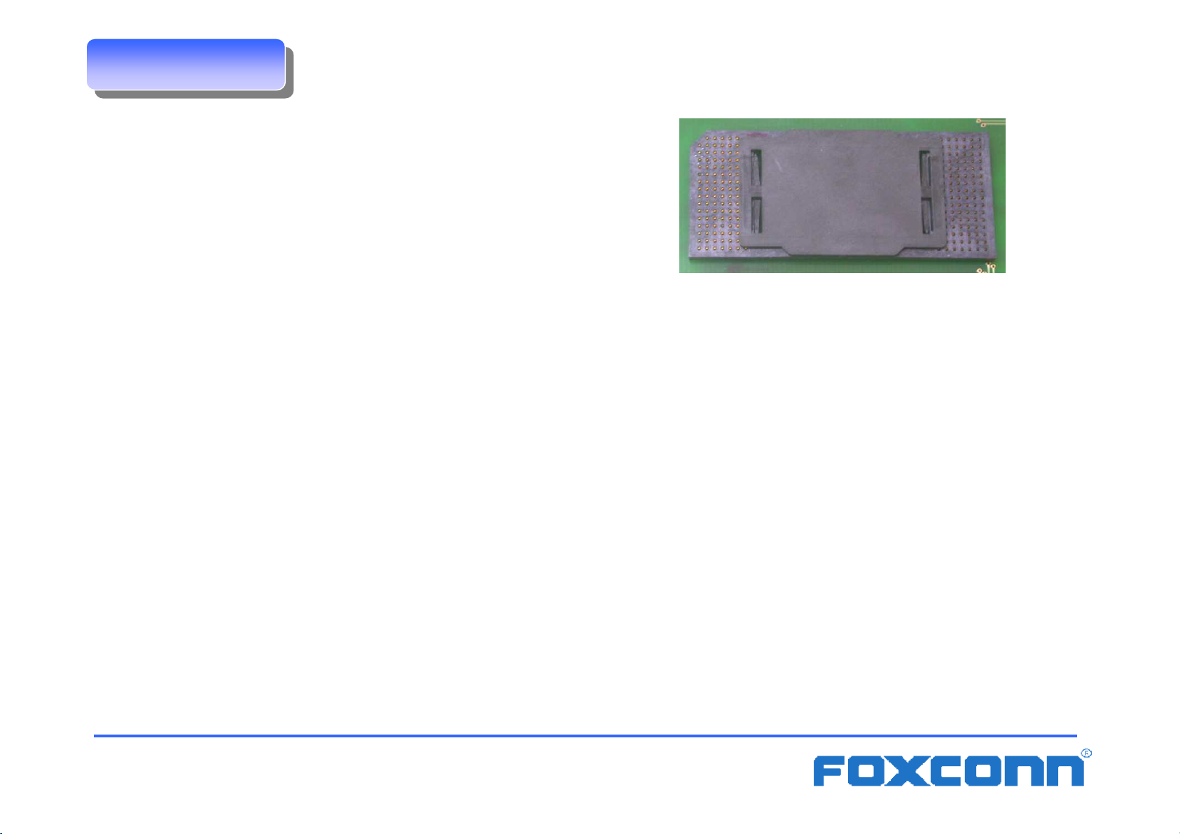
• Name : LIF 223 Socket
• Pin count : 223 Positions
• Socket envelop: 50.34mmx21.94mmx2.24mm
• Interface:
Carrier side : Low insertion force with 2 point contact for
m PGA pin on the package
PCB side : ∅∅∅∅0.76mm solder ball
Solder ball coplanarity 0.20mm max
Confidential
ICS/DQA
2006/03/20 Page:3
Page 4
Socket outline dimension
Socket outline dimension
Socket outline dimension
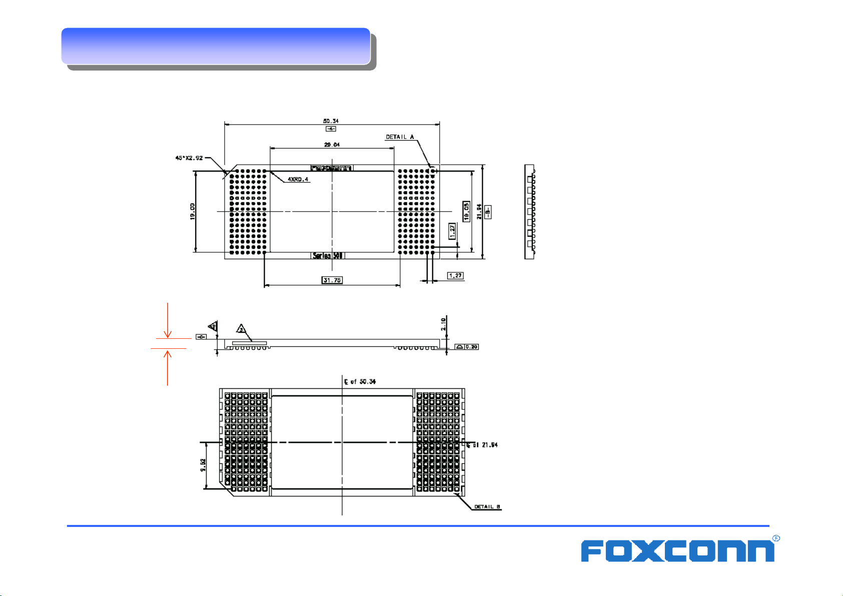
The outline dimensions of LIF223 socket are shown as below.
Dim H
Confidential
ICS/DQA
Dim H: 2.235+/- 0.127mm after
soldering process
2006/03/20 Page:4
Page 5
Socket Pick & Place Design
Socket Pick & Place Design
Socket Pick & Place Design
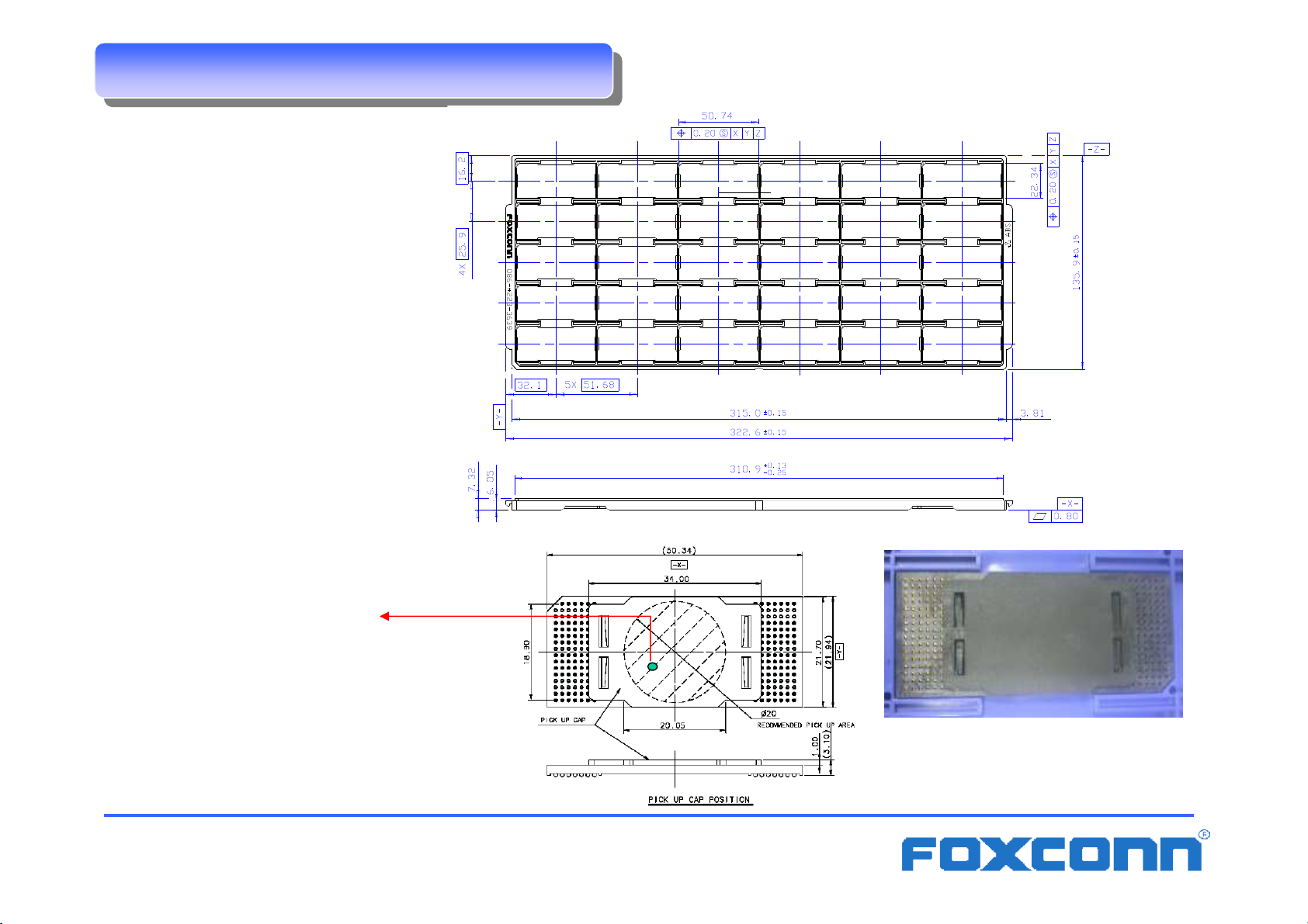
Foxconn’s packaging tray
dimension:
Center of Gravity
(Recommended Pick-up Location)
Confidential
ICS/DQA
Relation between socket
and tray pocket
2006/03/20 Page:5
Page 6

Recommended Soldering Condition
Recommended Soldering Condition
Recommended Soldering Condition
Defining the location of tested point
In order to ensure the quality of all the solder balls after reflow process,the
profile of the point at lowest temperature and highest temperature must be
controlled.The point at lowest temperature and highest temperature were
defined as the following figure.
The test point of solder ball
Confidential
ICS/DQA
Thermocouple
2006/03/20 Page:6
Page 7

Recommended Soldering Condition
Recommended Soldering Condition
Recommended Soldering Condition
Solder Ball Temperature Profile
Recommend profile of lead-free type is showed as below.
230~250oPeak temp.
o
218
C
Slope < 3
150oC
o
C/sec
Soak time
60 - 90 sec
_continued
_continued
_continued
Time above
liquidous
40 – 120 sec
Slope < 3oC/sec
Solder paste:Tamura (lead free type)
Stencil thickness:0.14~0.15mm
Stencil diameter:0.55~0.65mm
Confidential
ICS/DQA
2006/03/20 Page:7
Page 8

Socket actuation Introduce
Socket actuation Introduce
Socket actuation Introduce
Insert Carrier on Socket
1.Remove the cap with two fingers by vertical force.
vertical removal force
Confidential
ICS/DQA
2006/03/20 Page:8
Page 9

Socket actuation Introduce
Socket actuation Introduce
Socket actuation Introduce
_continued
_continued
_continued
2.1 Make sure pin 1 indicator is on your bottom-left side.
2.2 Aim at the socket and place the carrier carefully into the socket by purely vertical motion,
Press the Carrier lightly by fingers to make sure there is no gap between Carrier and
socket.
2.3 Visually inspect if the Carrier is seated well into the socket. If not, take out the CPU with
purely vertical motion and repeat the step to re-load the CPU.
Note
:a. The red mark on Carrier should be match with the mark on socket before carrier insertion as
below figure.
b. The alignment wall of Carrier should be match with the alignment hole of socket before carrier
insertion as below figure.
Pin 1
indicator
of socket
Pin 1
Alignment wall
of Carrier
Alignment edge
of socket
Chamfer
of Carrier
Confidential
ICS/DQA
2006/03/20 Page:9
Page 10

Socket actuation Introduce
Socket actuation Introduce
Socket actuation Introduce
3.Push down the carrier with two hands by vertical down force.
_continued
_continued
_continued
vertical down force
Confidential
ICS/DQA
2006/03/20 Page:10
Page 11

Socket actuation Introduce
Socket actuation Introduce
Socket actuation Introduce
Remove Carrier from Socket
1. Hold the four corners of the carrier with two hands. Remove the Carrier by vertical up force.
_continued
_continued
_continued
vertical up force
Confidential
ICS/DQA
2006/03/20 Page:11
Page 12

Unpacking Guide
Unpacking Guide
Unpacking Guide
1. Place the box and make sure the logo ‘Foxconn’ is in the right direction.
2. Use a knife the open the box.
3. Take out the packing foams.
4. Hold the sockets with two hands carefully.
5. Lift up and put the socket on the table.
Confidential
ICS/DQA
2006/03/20 Page:12
Page 13

Unpacking Guide
Unpacking Guide
Unpacking Guide
6. Locate the opening of the vacuum bag.
7. Tear the bag gently without shaking the tray.
8. Remove the vacuum bag.
9. Customer application.
_continued
_continued
_continued
Confidential
ICS/DQA
2006/03/20 Page:13
Page 14

How to reserve Socket
How to reserve Socket
How to reserve Socket
If the vacuum package is opened, we suggest the following method to reserve
the remain socket if sockets cannot used up.
1. Put the remain socket on the hard tray and put back the hard tray into the
vacuum package.
2. Keep the package in the following condition.
Humidity <60% RH , Temperature under 22~50。C (Same as
chipset’s reserved condition is preferred. )
3. The reserved time limit is six months.
4. After customer reused the remain socket, the socket does not need to
bake.
5. Put the remain socket on the hard tray and put back the hard tray into the
vacuum package.
Confidential
ICS/DQA
2006/03/20 Page:14
 Loading...