

Page 1

Statement:
This manual is the intellectual property of Foxconn, Inc. Although the
information in this manual may be changed or modified at any time,
Foxconn does not obligate itself to inform the user of these changes.
Trademark:
All trademarks are the property of their respective owners.
Version:
User’s Manual V1.1 in English for 755/760A01 series motherboard.
P/N:91-181-755-11-00
Symbol description:
Note: refers to important information that can help you to use motherboard
better.
Attention: indicates that it may damage hardware or cause data loss,
and tells you how to avoid such problems.
Warning: means that a potential risk of property damage or physical
injury exists.
More information:
If you want more information about our products, please visit Foxconn’s
website:
755A01-English preface-031504.p65 2004-3-26, 16:061
www.foxconnchannel.com
Page 2

Item Checklist:
Thank for your purchasing Foxconn’s 755/760A01 series motherboard. Please
check the package; if there are missing or damaged items, contact your distribu-
tor as soon as possible.
755/760A01 series motherboard (x1)
Foxconn Utility CD (x1)
User’s Manual (x1)
755/760A01 series Flyer (x1)
SATA RAID user’s Manual (x1)
IDE Ribbon cable (x1)
FDD Ribbon cable (x1)
I/O Shield (x1)
SPDIF Cable (x1) (optional)
USB 2.0 Cable (x1) (optional)
S-ATA Signal Cable (x2)
S-ATA Power Cable (x1)
SiS964 RAID Installation Support Disk (x1)
Silicon 3112A RAID Installation Support Disk (x1)
755A01-English preface-031504.p65 2004-3-26, 16:062
Page 3

Declaration of conformity
HON HAI PRECISION INDUSTRY COMPANY LTD
66 , CHUNG SHAN RD., TU-CHENG INDUSTRIAL DISTRICT,
TAIPEI HSIEN, TAIWAN, R.O.C.
declares that the product
Motherboard
755/760A01 series
is in conformity with
(reference to the specification under which conformity is declared in
accordance with 89/336 EEC-EMC Directive)
EN 55022/A1: 2000 Limits and methods of measurements of radio disturbance
characteristics of information technology equipment
EN 61000-3-2/A14:2000 Electromagnetic compatibility (EMC)
Part 3: Limits
Section 2: Limits for harmonic current emissions
(equipment input current <= 16A per phase)
EN 61000-3-3/A1:2001 Electromagnetic compatibility (EMC)
Part 3: Limits
Section 2: Limits of voltage fluctuations and flicker in low-voltage
supply systems for equipment with rated current <= 16A
EN 55024/A1:2001 Information technology equipment-Immunity characteristics limits
and methods of measurement
Signature : Place / Date : TAIPEI/2004
Printed Name : James Liang Position/ Title : Assistant President
755A01-English preface-031504.p65 2004-3-26, 16:063
Page 4

Declaration of conformity
Trade Name: Foxconn
Model Name:
Responsible Party: PCE Industry Inc.
Address: 458 E. Lambert Rd.
Telephone: 714-738-8868
Facsimile: 714-738-8838
Equipment Classification: FCC Class B Subassembly
Type of Product: Motherboard
Manufacturer: HON HAI PRECISION INDUSTRY
Address: 66 , CHUNG SHAN RD., TU-CHENG
755/760A01
Fullerton, CA 92835
COMPANY LTD
INDUSTRIAL DISTRICT, TAIPEI HSIEN,
TAIWAN, R.O.C.
Supplementary Information:
This device complies with Part 15 of the FCC Rules. Operation is subject to the
following two conditions : (1) this device may not cause harmful interference, and (2)
this device must accept any interference received, including interference that may
cause undesired operation.
Tested to comply with FCC standards.
Signature : Date : 2004
755A01-English preface-031504.p65 2004-3-26, 16:064
Page 5

Table of Contents
Chapter 1
Main Features .............................................................................................. 2
Motherboard Layout .................................................................................... 4
Chapter 2
CPU .............................................................................................................. 9
Memory ...................................................................................................... 12
Power Supply ............................................................................................ 16
Rear Panel Connectors .............................................................................. 17
Other Connectors ...................................................................................... 19
Expansion Slots ......................................................................................... 26
Jumpers ..................................................................................................... 28
Chapter
Enter BIOS Setup ....................................................................................... 33
Main menu ................................................................................................. 33
Standard CMOS Features .......................................................................... 35
BIOS Features ........................................................................................... 38
Advanced BIOS Features .......................................................................... 39
Advanced Chipset Features ...................................................................... 42
DRAM Configuration .................................................................................. 43
Integrated Peripherals ................................................................................ 45
Power Management Setup ......................................................................... 50
PnP/PCI Configurations ............................................................................... 54
PC Health Status ........................................................................................ 55
Frequency/Voltage Control......................................................................... 56
Load Fail-Safe Defaults ............................................................................. 57
Load Optimized Defaults ............................................................................ 57
Set Supervisor/User Password ................................................................. 57
Save & Exit Setup ...................................................................................... 58
Exit Without Saving .................................................................................... 58
3
Product Introduction
Installation Instructions
BIOS Description
755A01-English preface-031504.p65 2004-3-26, 16:065
Page 6

Table of Contents
Chapter
Utility CD content ........................................................................................ 60
Start to install drivers ................................................................................. 61
Install IDE Driver ......................................................................................... 61
Install SiS RAID (optional) .......................................................................... 62
Install AGP Driver ....................................................................................... 62
Install DirectX 9.0b ..................................................................................... 63
Install USB 2.0 Driver ................................................................................. 63
Using 4-/6-Channel Audio .......................................................................... 64
Install LAN Driver ....................................................................................... 70
Install SiI3112 SATA RAID Driver ................................................................. 71
Install SuperUtility ....................................................................................... 71
Install Adobe Reader ...... ............................................................................ 72
Install Norton Internet Security 2004 .......................................................... 72
Chapter
SuperStep ................................................................................................. 74
SuperUpdate .............................................................................................. 77
SuperLogo ................................................................................................. 82
Chapter
4
5
6
Driver CD Introduction
Directions for Bundled Software
Special BIOS Functions
SuperBoot ................................................................................................. 85
SuperBIOS-Protect .................................................................................... 86
SuperSpeed ............................................................................................... 87
SuperRecovery ......................................................................................... 88
755A01-English preface-031504.p65 2004-3-26, 16:066
Page 7

Warning:
1. Attach the CPU and heatsink using silica gel to ensure full contact.
2. It is suggested to select high-quality, certified fans in order to avoid
damage to the motherboard and CPU due to high temperature.
3. Never turn on the machine if the CPU fan is not properly installed.
4. Ensure that the DC power supply is turned off before inserting or
removing expansion cards or other peripherals, especially when
you insert or remove a memory module. Failure to switch off the DC
power supply may result in serious damage to your system or
memory module.
Warning:
We cannot guarantee that your system will operate normally while
over-clocked. Normal operation depends on the over-clock capacity of
your device.
Attention:
Since BIOS programs are upgraded from time to time, the BIOS
description in this manual is just for reference. We do not guarantee
that the content of this manual will remain consistent with the actual
BIOS version at any given time in the future.
Attention:
The pictures of objects used in this manual are just for your reference.
Please refer to the physical motherboard.
755A01-English preface-031504.p65 2004-3-26, 16:067
Page 8

This page is intentionally left blank.
755A01-English preface-031504.p65 2004-3-26, 16:068
Page 9
Chapter
Thank you for buying Foxconn’s 755/760A01 series
motherboard. This series of motherboard is one of our new
products, and offers superior performance, reliability and
quality, at a reasonable price. This motherboard adopts the
advanced SiS
computer platform with a high integration-compatibility-per-
formance price ratio.
This chapter includes the following information:
1
1
755/760+SiS 964 chipset, providing users a
Main Features
Motherboard Layout
755A01-032604.p65 2004-3-26, 15:281
Page 10

Chapter 1 Product Introduction
Main Features
Size:
ATX form factor of 12” x 8.8”
Microprocessor:
Supports AMD
®
Athlon64 Processor Hyper Transport
8/16 links
Supports AMD
®
Athlon64 Processor Hyper Transport
1600 MT/s bandwidth
Chipset:
SiS Chipset: SiS
755/760 (North Bridge) +SiS 964 (South Bridge)
System Memory
Three 184-pin DDR DIMM slots
Supports PC3200/2700/2100 memory
Supports 128/256/512 Mb technology up to 3GB
USB 2.0 Port
Supports hot-plug
Eight USB 2.0 ports (four rear panel ports, two onboard USB headers
providing four extra ports)
Supports wake-up from S1 and S3 mode
Supports USB 2.0 protocol up to 480Mbps transmission rate
TM
Technology with
TM
Technology up to
Onboard Serial ATA
150MBps transfer rate
Supports four S-ATA devices, such as HDD, etc
Supports Raid0, Raid1 and JBOD
Onboard 1394(optional)
Supports hot-plug
With rate of transmission at 400Mbps
Self-configured addressing
Supports two independent 1394 units synchronously at most, such as HDD,
CD-ROM
2
755A01-032604.p65 2004-3-26, 15:282
755/760A01 Series User Manual
Page 11

Chapter 1 Product Introduction
Onboard LAN (optional)
Supports10/100/1000 (optional) Mbps Ethernet
LAN interface built-in on board
Onboard Audio
AC’ 97 2.3 Specification Compliant
Supports S/PDIF output
Onboard Line-in jack, Microphone-in jack, Line-out jack
Supports 5.1 channels audio (setting via software)
BIOS
Licensed advanced AWARD (Phoenix) BIOS, supports flash ROM, Plug-and-
Play
Supports IDE, CD-ROM, SCSI HDD or USB device boot up
Green Function
Supports ACPI (Advanced Configuration and Power Interface)
Supports S0 (normal), S1 (power on suspend), S3 (suspend to RAM), S4
(suspend to disk-depends on OS), and S5 (soft-off)
Expansion Slots
5 PCI slots
1 AGP slot
Onboard Graphics (only for 760A01)
Supports integrated VGA display function
AGP 8X support
Supports AGP 8X graphics cards
Advanced Features
PCI 2.2 Specification Compliant
Supports Windows98/2000/ME/XP soft-off
Supports Wake-up On LAN, Wake-up on Modem functions
Supports PC Health function (capable of monitoring system voltage, CPU,
system temperature, and fan speed)
755/760A01 Series User Manual
755A01-032604.p65 2004-3-26, 15:283
3
Page 12
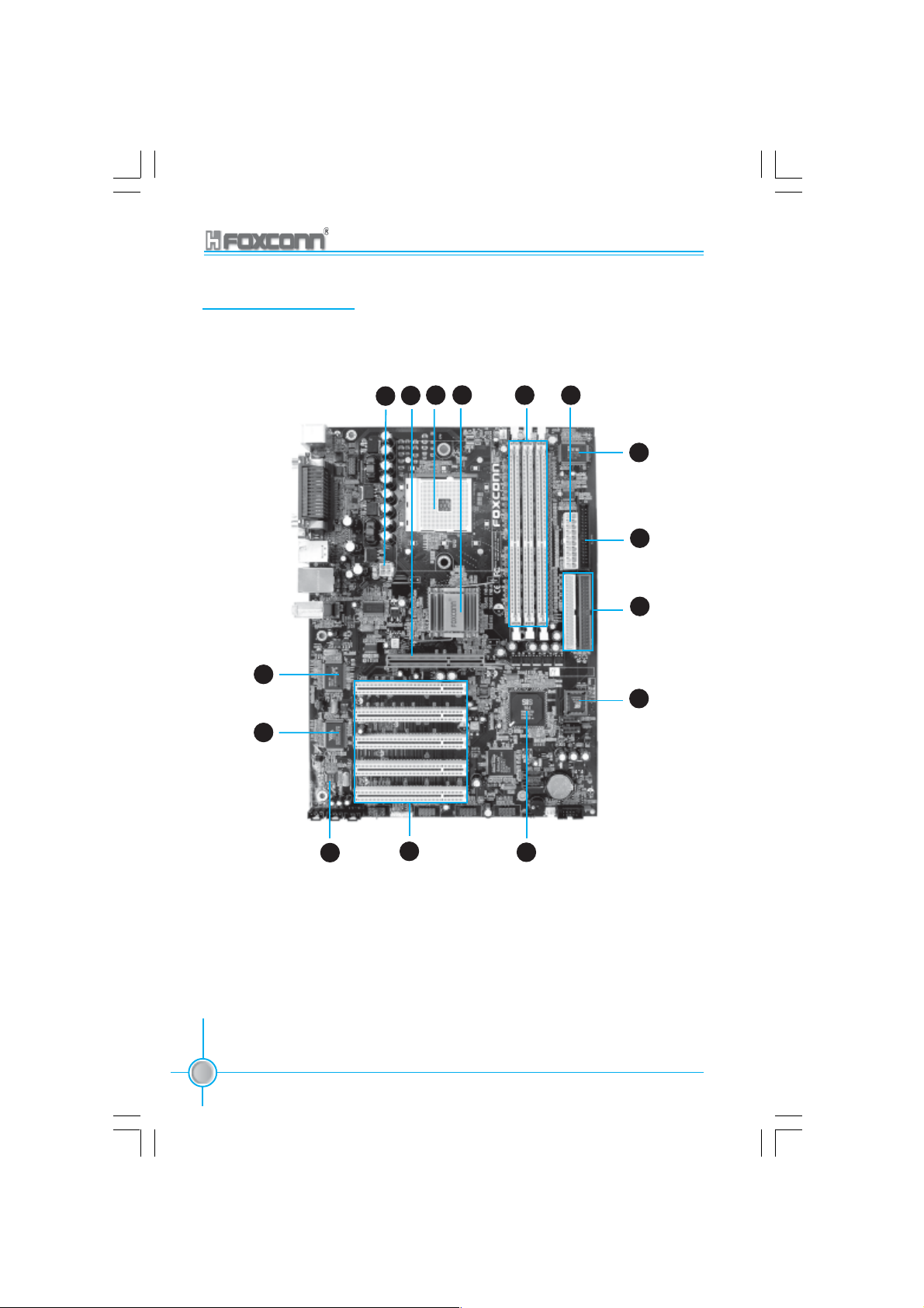
Motherboard Layout
Chapter 1 Product Introduction
15
14
1
3 4 5 6
2
7
8
9
10
13
4
755A01-032604.p65 2004-3-26, 15:284
755/760A01 Series User Manual
1112
Page 13

Chapter 1 Product Introduction
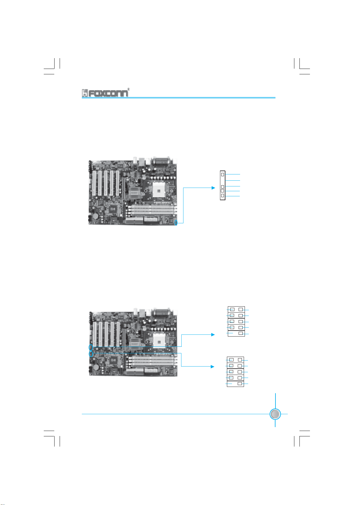
ATX 12V connector
1
This power connector connects the 4-pin 12V plug from the ATX 12V power
supply.
AGP slot
2
This Accelerated Graphics Port (AGP) slot supports 1.5V AGP8X mode
graphics cards for 3D graphical applications.
CPU socket
3
A 754-pin surface mount, Zero Insertion Force (ZIF) Socket for the AMD
Athlon64 Processor, Support HyperThansportTM Technology with 8/16 links,
up to 1600MT/s bandwidth.
North Bridge controller
4
The SiS 755/760 integrate a high performance host interface for the AMD
Athlon64 Processor, and SiS MuTIOL technology.
DDR DIMM sockets
5
These three 184-pin DIMM sockets support up to 3GB system memory
using unbuffered non-ECC PC3200/2700/2100 DDR DIMMS.
®
®
ATX power connector
6
This 20-pin connector connects to an ATX power supply. The power supply
must have at least 1A on the +5V standby lead (+5VSB).
Super I/O controller
7
The ITE8705F controller Super I/O provides support that includes floppy,
serial ports, and parallel port to rest of platform through the SiS
SiS 964 via the Low Pin Count (LPC) interface.
Floppy disk connector
8
This connector accommodates the provided ribbon cable for the floppy
disk drive. One side of the connector is slotted to prevent incorrect insertion
of the floppy disk cable.
755/760A01 Series User Manual
755A01-032604.p65 2004-3-26, 15:285
755/760 and
5
Page 14

Chapter 1 Product Introduction
9
IDE connectors
These dual-Channel bus master IDE connectors support Ultra DMA 133/
100/66. Both the primary (blue) and secondary (white) connectors are slotted
to prevent incorrect insertion of the IDE ribbon cable.
Flash ROM
10
This 4Mb firmware contains the programmable BIOS program.
South Bridge controller
11
Referred to as the SiS 964 MuTIOL Media I/O, this controller integrates the
audio controller with AC’97 interface, Ethernet MAC, Universal Serial Bus
Host controller, S-ATA interface, IDE Master/Slave controllers and the
MuTIOL connect to PCI bridge.
PCI Slots
12
These five 32-bit PCI 2.2 expansion slots support bus master PCI cards
like SCSI or LAN cards with 133MB/s maximum throughput.
Audio CODEC
13
The ALC655 is an AC’97 CODEC that allows 6-Channel audio playback. The
audio CODEC provides six DAC channel for 5.1 surround sound, S/PDIF
output and Line-in stereo inputs, integrated headphone amplifier, greater
than 90dB dynamic range with the jack sense and jack enumeration feature
1394 controller(optional)
14
VT6307 is the controller for IEEE1394a on motherboard. The VT6307 is a
complete small package single chip PCI solution at 400Mbps, low power
seamless plug and play connections to the latest IEEE 1394 enabled
devices.
LAN controller(optional)
15
The RTL8110S-32 Gigabit Ethernet is a single-chip solution for LAN on
motherboard (LOM) applications, and supports 10/100/1000 Mbps data
transfer rates. (For -K models)
The RTL8110C Ethernet is a single-chip solution for LAN on motherboard
(LOM) applications, and supports 10/100 Mbps data transfer rates. (For -L
models)
6
755A01-032604.p65 2004-3-26, 15:286
755/760A01 Series User Manual
Page 15

Chapter
This chapter introduces the hardware installation process,
including the installation of the CPU and memory. It also
addresses the connection of your power supply, use of the
rear panel connectors, connection of hard drive and floppy
drive data cables, and setting up various other feature of the
motherboard. Caution should be exercised during the installation process. Please refer to the motherboard layout
prior to any installation and read the contents in this chapter
carefully.
2
2
Chapter 1 Product Introduction
This chapter includes the following information:
755/760A01 Series User Manual
755A01-032604.p65 2004-3-26, 15:287
CPU
Memory
Power Supply
Rear Panel Connectors
Other Connectors
Expansion Slots
Jumpers
7
Page 16

Chapter 2 Installation Instructions
Notes:
Take note of the following precautions before you install components
or change settings.
1. Use a grounded wrist strap or touch a safely grounded object,
such as an attached power supply, before handling components
to avoid damaging them due to static electricity.
2. Unplug the power cord before opening your chassis or touching
any components.
3. Hold components by their edges to avoid touching any exposed
integrated circuits (ICs).
4. Whenever you uninstall a component, place it on a grounded
anti-static pad or into the anti-static bag that it came in.
8
755A01-032604.p65 2004-3-26, 15:288
755/760A01 Series User Manual
Page 17
Chapter 2 Installation Instructions
CPU
This motherboard supports AMD® Athlon64 processors with a 1600 MT/s band-
width and HyperThansport
TM
Technology.
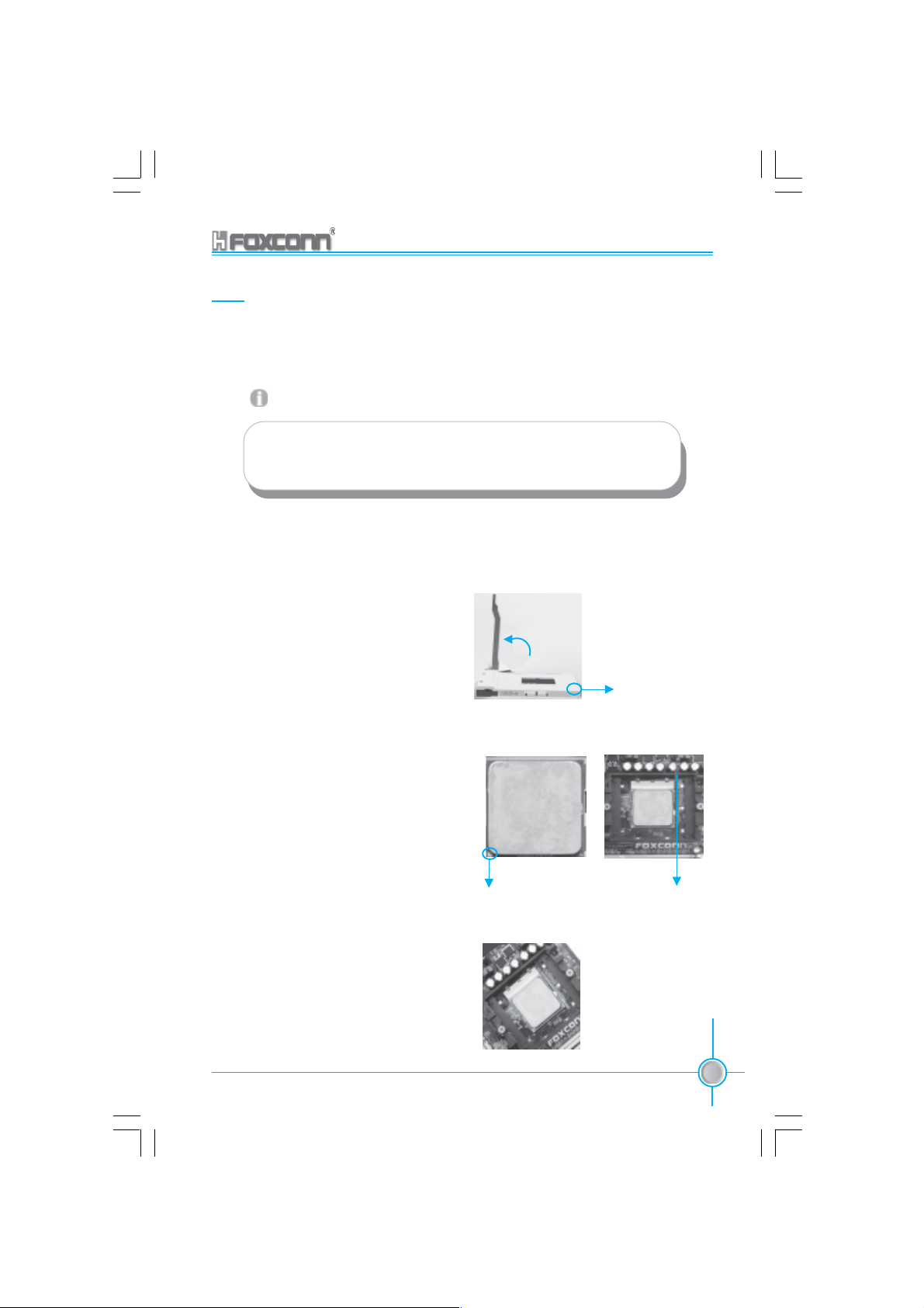
Attention:
The CPU pins must be properly aligned with the holes in the
socket, otherwise the CPU may be damaged.
Installation of CPU
Follow these steps to install the CPU.
1. Unlock the socket by pressing the lever sideways, then lift it up to a 90
o
angle.
2. Align the cut edge to the gap in the
base of the socket. Carefully insert
the CPU into the socket until it fits in
place.
3. When the CPU is in place, press it
firmly on the socket while you push
down the socket lever to secure the
CPU. The lever clicks on the side tab
to indicate that it is locked.
Cut edge
90
o
Gap in the base
Push down the socket
lever to secure the CPU.
755/760A01 Series User Manual
755A01-032604.p65 2004-3-26, 15:289
9
Page 18
Chapter 2 Installation Instructions
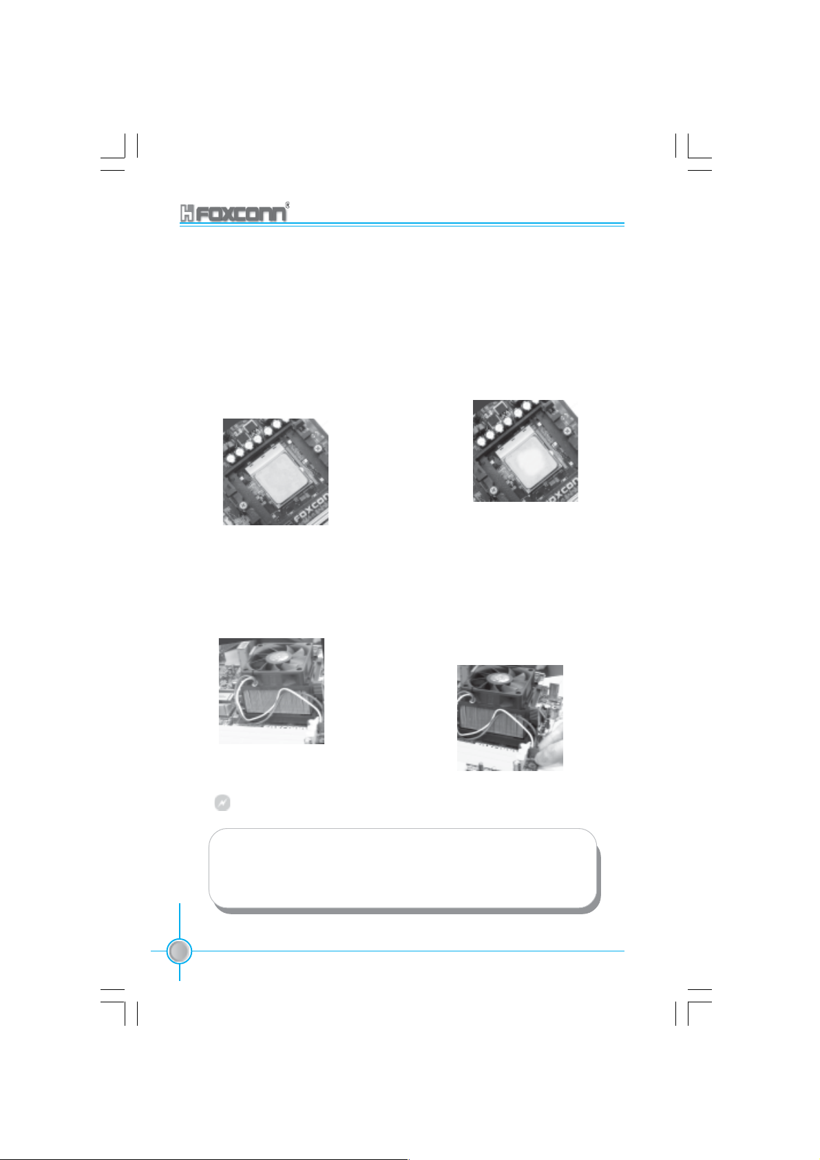
Installation of CPU Fan
New technology allows processors to run at higher and higher frequencies.
To avoid problems arising from high-speed operation, for example,
overheating, you need to install the proper fan. The following procedure is
provided for reference only, please refer to your CPU fan user guide for the
actual procedure.
1.Locate the CPU retention mechanism
base (surrounds the CPU socket).
3. Attach the fan to the base.
2.If required, apply a light coating of
silica gel to the top of the CPU.
NOTE: The CPU heatsink may have
a pre-applied thermal compound. In
that case, the silica gel is not required.
4.Connect the fan’s power cable
to the appropriate 3-pin terminal
on the motherboard.
Warning:
Excessive temperature will severely damage the CPU and
system. Therefore, make sure that the cooling fan works normally at all times in order to prevent overheating and damaging
to the CPU.
10
755A01-032604.p65 2004-3-26, 15:2810
755/760A01 Series User Manual
Page 19

Chapter 2 Installation Instructions
CPU Qualified Vendor List
The following table lists the CPUs that have been tested and qualified for use
with this motherboard.
Vendor Type
AMD Athlon64 3000+
AMD Athlon64 3200+
AMD Athlon64 3400+
755/760A01 Series User Manual
755A01-032604.p65 2004-3-26, 15:2811
11
Page 20
Chapter 2 Installation Instructions
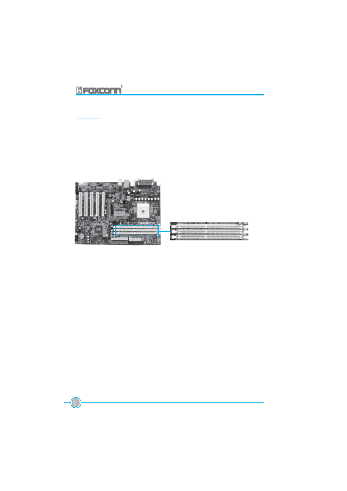
Memory
This motherboard includes three 184-pin slots with 266/333/400 MHz Single
Channel DDR DRAM interface, You must install at least one memory module to
ensure normal operation. If you install three modules, they must be the same
speed. Mixing memory modules from different manufactures are not
recommended.
DIMM1
DIMM2
DIMM3
12
755A01-032604.p65 2004-3-26, 15:2812
755/760A01 Series User Manual
Page 21
Chapter 2 Installation Instructions
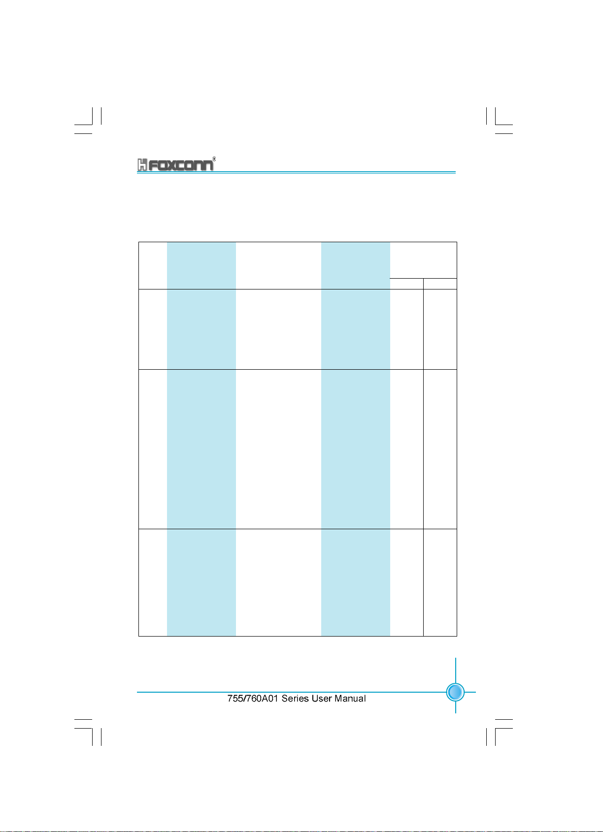
Recommended Memory Configurations
The following table lists the recommended memory configurations.
Number
of
DIMMs
CA1
Socket 1*
CA2
Socket 2*
CA2
Socket 3*
Maximum
Frequency
(MHz)
1T
1 x8 single rank or x16 empty empty 200 200
1 empty x8 single rank or x16 empty 200 200
1 empty empty x8 single rank or x16 200 200
1 x8 double rank empty empty 200 200
1 empty x8 double rank empty 200 200
1 empty empty x8 double rank 200 200
2 x8 single rank or x16 x8 single rank or x16 empty 200 200
2 x8 single rank or x16 x8 double rank empty 200 200
2 x8 single rank or x16 empty x8 single rank or x16 200 200
2 x8 single rank or x16 empty x8 double rank 200 200
2 x8 double rank x8 single rank or x16 empty 200 200
2 x8 double rank x8 double rank empty 166 166
2 x8 double rank empty x8 single rank or x16 200 200
2 x8 double rank empty x8 double rank 166 166
2 empty x8 single rank or x16 x8 single rank or x16 166 200
2 empty x8 single rank or x16 x8 double rank 100 200
2 empty x8 double rank x8 single rank or x16 100 200
2 empty x8 double rank x8 double rank 100 166
3 x8 single rank or x16 x8 single rank or x16 x8 single rank or x16 166 200
3 x8 single rank or x16 x8 single rank or x16 x8 double rank 100 166
3 x8 single rank or x16 x8 double rank x8 single rank or x16 100 166
3 x8 single rank or x16 x8 double rank x8 double rank 100 166
3 x8 double rank x8 single rank or x16 x8 single rank or x16 166 166
3 x8 double rank x8 single rank or x16 x8 double rank 100 166
3 x8 double rank x8 double rank x8 single rank or x16 100 166
3 x8 double rank x8 double rank x8 double rank 100 166
2T
755A01-072104.p65 2004-7-21, 8:2713
13
Page 22
Chapter 2 Installation Instructions
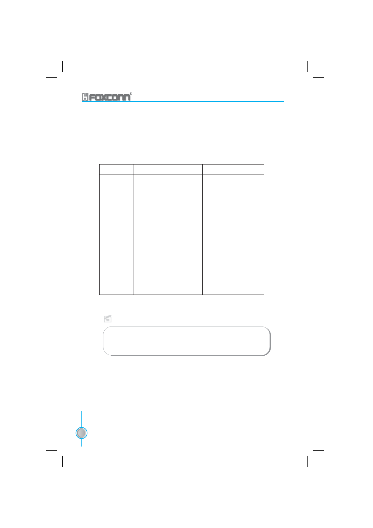
Memory Qualified Vendor List
The following table lists the memory modules that have been tested and quali-
fied for use with this motherboard.
Vendor Type Size
Kingmax PC3200 (DDR 400) 256M, 512M
Kingmax PC2100 (DDR 266) 256M
Kingston PC3200 (DDR 400) 256M, 512M
Hynix PC3200 (DDR 400) 256M, 512M
Nanya PC3200 (DDR 400) 256M
Apacer PC3200 (DDR 400) 256M, 512M
Apacer PC2700 (DDR 333) 512M
Geil PC3200 (DDR 400) 256M
VDATA PC3200 (DDR 400) 256M
RAMBO PC3200 (DDR 400) 256M, 512M
RAMBO PC2700 (DDR 333) 512M
Transend PC3200 (DDR 400) 256M, 512M
Twinmos PC3200 (DDR 400) 256M
Samsung PC3200 (DDR 400) 1G
Note:
Make sure to use only the tested and qualified DDR modules
listed above. Other DDR modules manufactured by other ven-
dors may not be suitable for this motherboard.
14
755A01-032604.p65 2004-3-26, 15:2814
755/760A01 Series User Manual
Page 23
Chapter 2 Installation Instructions
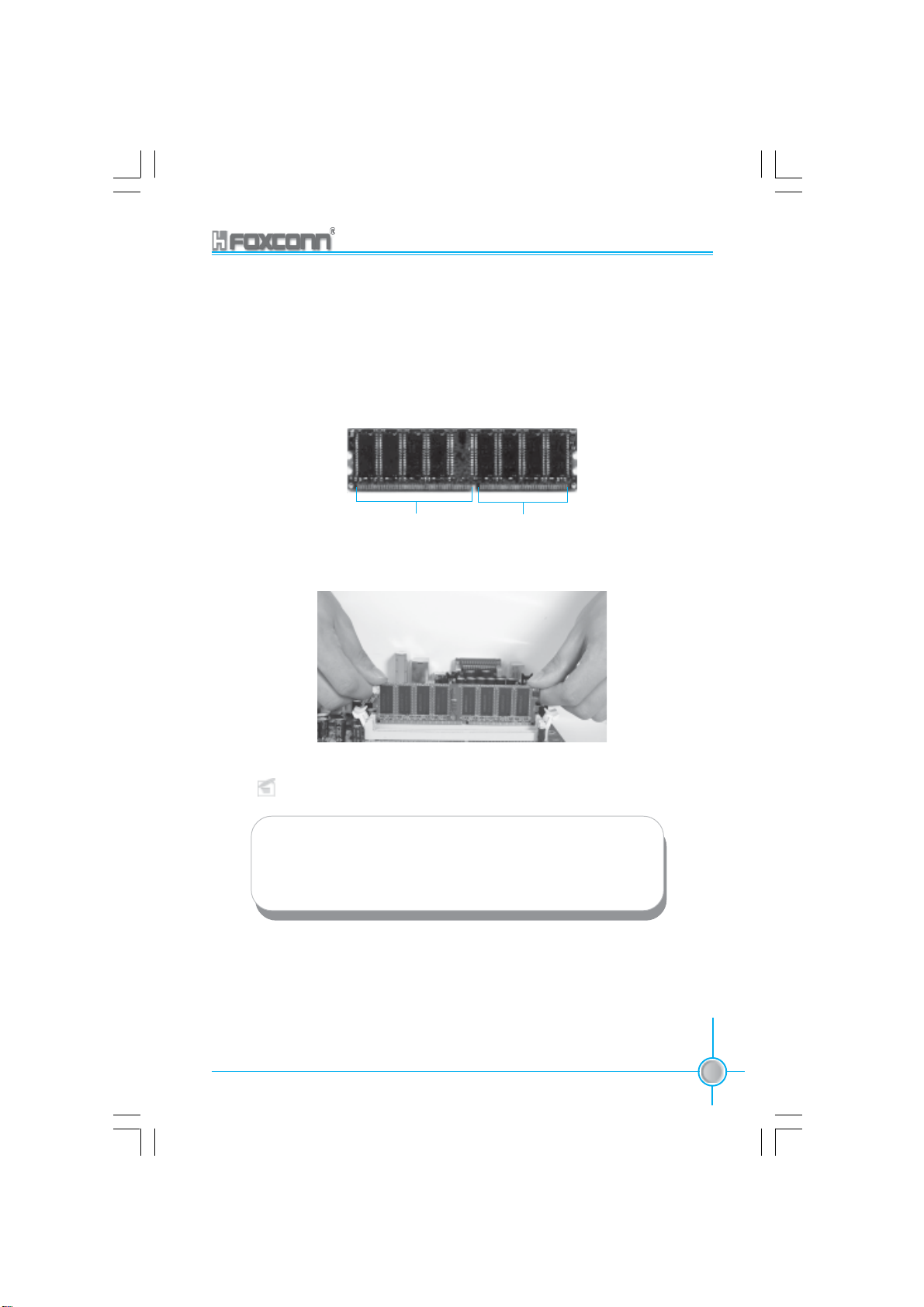
Installation of DDR Memory
1. There is only one gap in the center of the DIMM slot, and the memory
module can be fixed in one direction only.
2. Align the memory module to the DIMM slot, and insert the module
vertically into the DIMM slot.
104 Pins 80 Pins
3. The plastic clips at both sides of the DIMM slot will lock automatically.
Note:
Be sure to unplug the AC power supply before adding or re-
moving expansion cards or other system peripherals, espe-
cially the memory devices, otherwise your motherboard or the
system memory might be seriously damaged.
755/760A01 Series User Manual
755A01-032604.p65 2004-3-26, 15:2815
15
Page 24
Chapter 2 Installation Instructions
Power Supply
This motherboard uses an ATX power supply. In order to avoid damaging any
devices, make sure that they have been installed properly prior to connecting
the power supply.
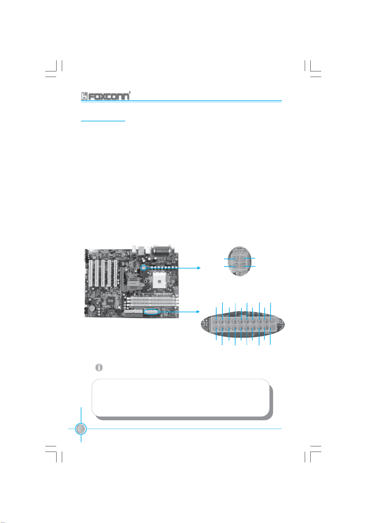
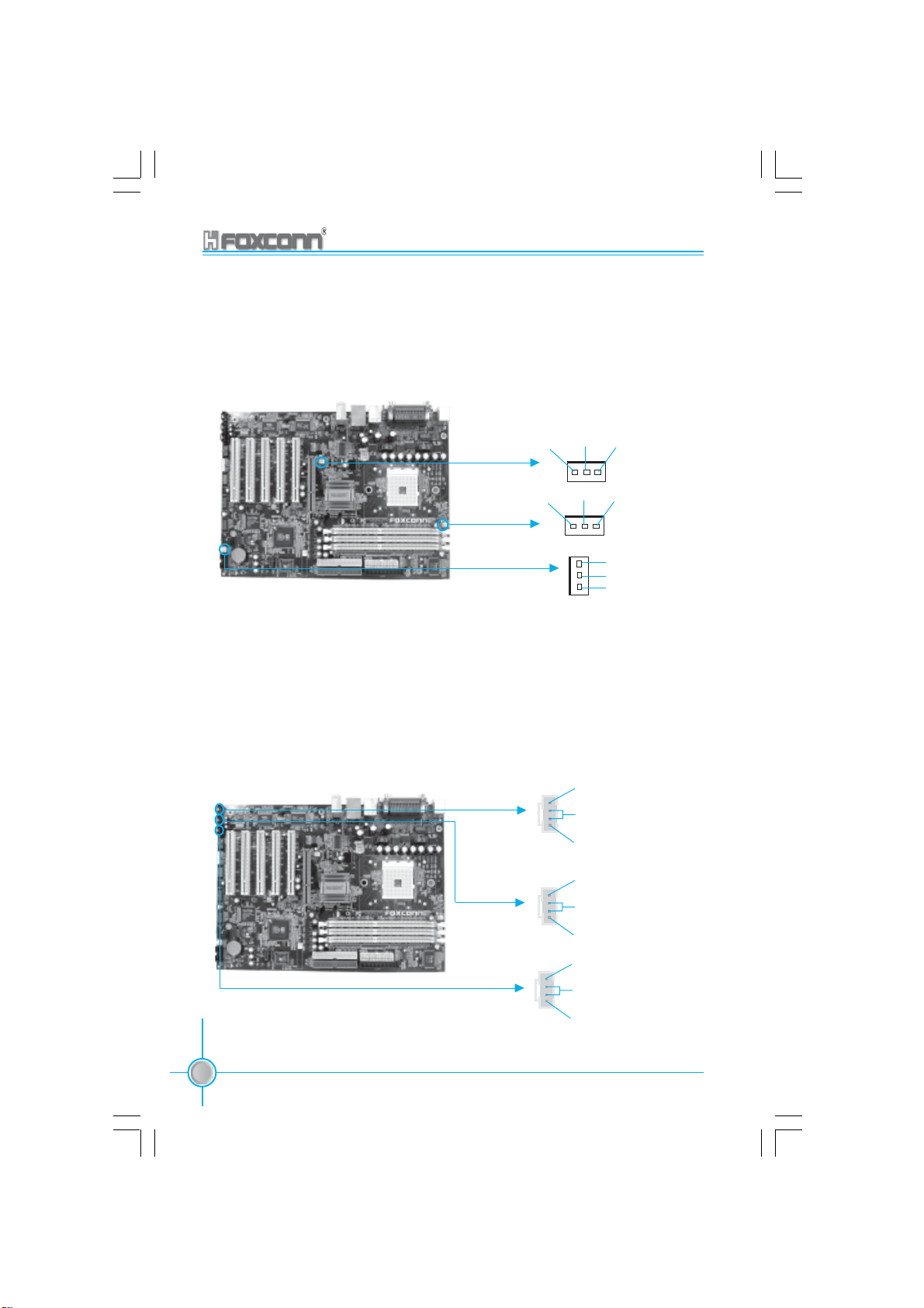
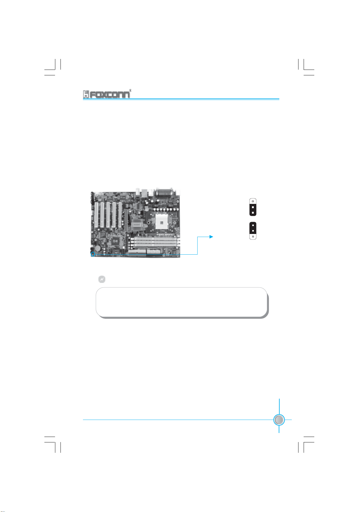
ATX 12V Power Connector: PWR2
The 4 pin ATX 12V power supply connects to PWR2 and provides power to the
CPU.
ATX Power Connector: PWR1
PWR1 is the ATX power supply connector. Make sure that the power supply
cable and pins are properly aligned with the connector on the motherboard.
Firmly plug the power supply cable into the connector and make sure it is secure.
ATX 12V Power Connector
12
GND
12V
3
GND
12V
4
Attention:
You have to press the power button for more than four seconds if
you change the default Instant-off setting to “Delay 4 Sec” for the
“Soft-Off by Power Button” option in the BIOS Power Management
Setup.
16
755A01-032604.p65 2004-3-26, 15:2816
755/760A01 Series User Manual
ATX 20-pin Power Connector
5V
5V
20
10
12V
5VSB
GND
GND
-5V GND PS-ON -12V
Pw-OK
GND
GND
5V
5V
GND 3.3V
GND
3.3V
3.3V
11
1
Page 25
Chapter 2 Installation Instructions
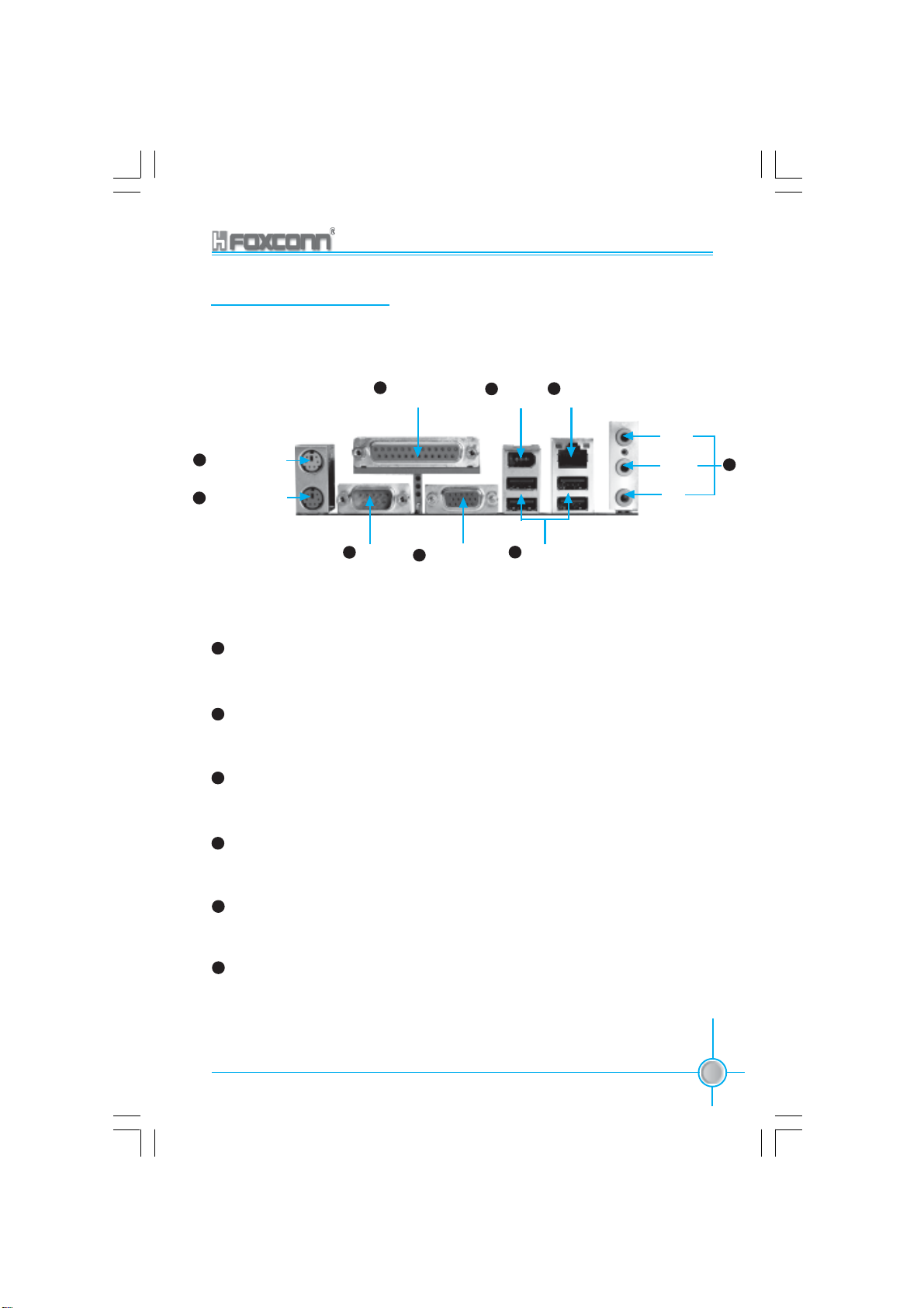
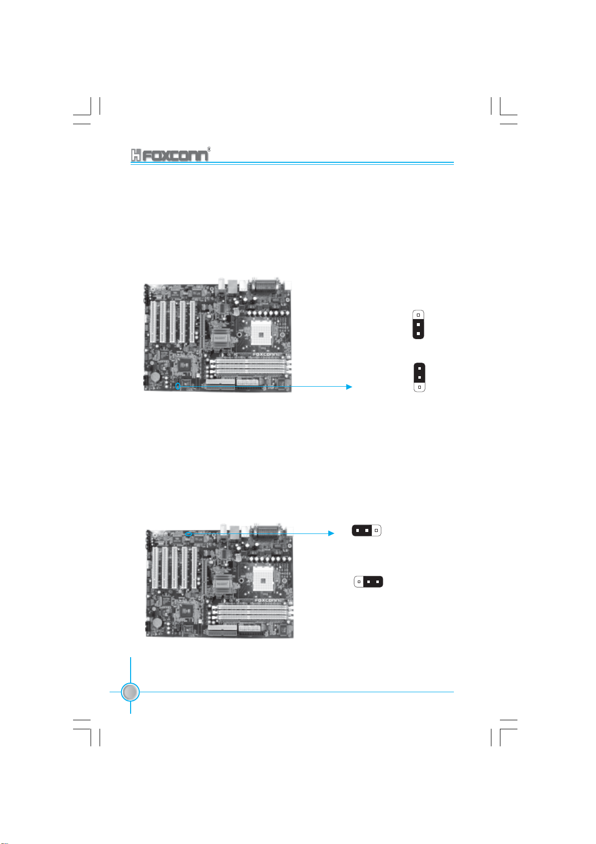
Rear Panel Connectors
This motherboard provides the following ports as below:
1
PS/2 Mouse Port
2
PS/2 Keyboard Port
1
PS/2 Mouse Port
Parallel Port
5
(Printer Port)
3 6
COM1
VGA Connector
4
(only for 760A01)
1394Port
7
(optional)
8
LAN Port
USB 2.0 Port
This green 6-pin connector is for a PS/2 mouse.
2
PS/2 Keyboard Port
This purple 6-pin connector is for a PS/2 keyboard.
3
Serial Ports: COM1
This two 9-pin COM1/COM2 ports are for pointing devices or other serial devices.
Line-in
Line-out
MIC
9
4
VGA Connector (only for 760A01)
The VGA connector is for output to VGA-compatible device.
5
Parallel Port: Printer Port
The 25-pin port connects a parallel printer,a scanner,or other devices.
6
USB 2.0 Ports
These four Universal Serial Bus (USB) ports are available for connecting USB 2.
0/1.1 devices.
755/760A01 Series User Manual
755A01-032604.p65 2004-3-26, 15:2817
17
Page 26
Chapter 2 Installation Instructions
7
1394 port (optional)
This digital interface supports electronic devices such as digital cameras,
scanners, and printers.
8
LAN Port
This port allows connection to a Local Area Network(LAN) through a network
hub.
9
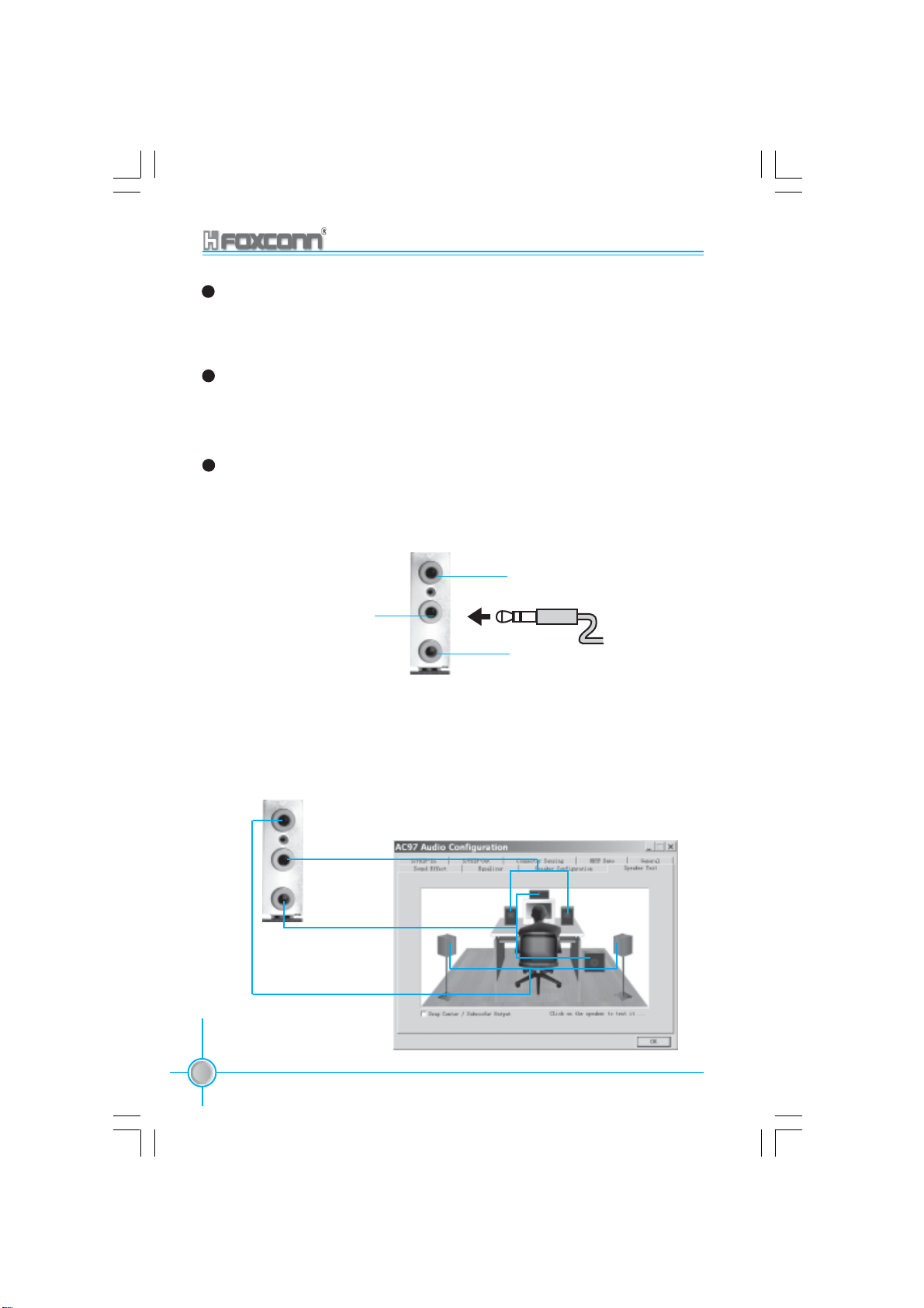
Audio Port
When using a two-channel sound source, the Line-out jack is used to connect
to speaker or headphone; the Line-in port connects to an external CD player,
tape player or other audio devices. The MIC is used to connect to the microphone.
Line-in
Line-out
MIC
When using a 6-channel sound source, connect the front speaker to the green
audio output; connect the surround sound speaker to the blue audio input;
connect the central speaker/sub woofer to the red MIC input, as being shown in
the following figure:
Blue
Green
Red
18
755A01-032604.p65 2004-3-26, 15:2818
755/760A01 Series User Manual
Front Left
Rear Left
Center
Front Right
Subwoofer
Rear Right
Page 27

Chapter 2 Installation Instructions
Other Connectors
This motherboard includes interfaces for FLOPPY, IDE HDD, SATA, USB, 1394,
IR module, CPU fan, system fan, and others.
FLOPPY
This motherboard includes a standard FLOPPY interface, supporting 360K, 720K,
1.2M, 1.44M, and 2.88M FDDs.
1
FLOPPY Connector
HDD connectors: PIDE & SIDE
These connectors support the provided UltraDMA133/100/66 IDE hard disk rib-
bon cable. Connect the cable’s blue connector to the primary (recommended)
or secondary IDE connector, then connect the gray connector to the Ultra DMA133/
100/66 slave device (hard disk drive) and the black connector to the Ultra DMA133/
100/66 master device. If you install two hard disks, you must configure the
second drive as a slave device by setting its jumper accordingly. Refer to the
hard disk documentation for the jumper settings.
Attention:
Ribbon cables are directional, therefore, make sure to always con-
nect with the cable on the same side as pin 1 of the PIDE/SIDE or
FLOPPY connector on the motherboard.
755/760A01 Series User Manual
755A01-032604.p65 2004-3-26, 15:2819
19
Page 28
Chapter 2 Installation Instructions
SIDE
1
PIDE
Front Panel Connector: FP1
This motherboard includes one connector for connecting the front panel switch
and LED indicator.
1 2
+ -
+ -
HD-LED
PWR-LED
RESET-SW
NC
9 10
PWR-SW
FPFP1!
Hard Disk LED Connector (HD-LED)
Attach the connector to the HD-LED on the front panel of the case; the LED will
flash while the HDD is in operation.
Reset Switch (RESET-SW)
Attach the connector to the Reset switch on the front panel of the case; the
system will restart when the switch is pressed.
Power LED Connector (PWR-LED)
Attach the connector to the power LED on the front panel of the case. The Power
LED indicates the power supply status. When the system is in S0 status, the
LED is on. When the system is in S1 status, the LED is blink. When the system
is in S3, S4, S5 staus, the LED is off.
.
20
755/760A01 Series User Manual
755A01-032604.p65 2004-3-26, 15:2820
Page 29
Chapter 2 Installation Instructions
IrDA Header: IR
The IrDA infrared transmission allows your computer to send and receive data
via an infrared ray. The relevant parameters for the BIOS Integrated Peripherals
should be set prior to using this function.
1
+5V
Empty
IRRX
GND
IRTX
IR
USB Header: F_USB 1, F_USB 2
Besides four USB ports on the rear panel, the series of motherboards also have
two 10-pin headers on board which may connect to front panel USB cable
(optional) to provide additional four USB ports.
VCC
D5-
D5+
GND
Empty
VCC
D7-
D7+
GND
Empty
1 2
9 10
F_USB 1
1 2
9 10
F_USB 2
VCC
D4-
D4+
GND
NC
VCC
D6-
D6+
GND
NC
755/760A01 Series User Manual
755A01-032604.p65 2004-3-26, 15:2821
21
Page 30
Chapter 2 Installation Instructions
Fan Connectors: CPU_FAN, FAN1, FAN2
There are three fan headers on this motherboard. These fans will be automatically turned off after the system enters suspend mode.
+12V
SENSE GND
+12V
SENSE GND
1
1
FAN1
CPU_FAN
1
GND
+12V
SENSE
FAN2
Audio Connectors: MODEM_IN, CD_IN, AUX_IN
To receive audio input from the CD-ROM, attach its audio connector to the CD_IN/
AUX_IN audio headers on the motherboard. The Modem_IN connector allows
the onboard audio to interface with a voice modem card with a similar connector. It
allows connecting the mono_in (such as a phone) or mono_out (such as a speaker)
between the onboard audio and the voice modem card.
PHONE_IN(from Modem)
1
GND
MODEM_IN
MONO_OUT(to Modem)
CD_L
1
GND
CD_R
AUX_R
1
GND
CD_IN
AUX_IN
22
755A01-032604.p65 2004-3-26, 15:2822
755/760A01 Series User Manual
AUX_L
Page 31

Chapter 2 Installation Instructions
1394 Header: F_1394(optional)
The 1394 expansion cable can be connected to either the front (provided that
the front panel of your chassis is equipped with the appropriate interface) or real
panel of the chassis.
1 2
TPA+
GND
TPB+
+12V(Fused)
NC
9 10
F_1394
TPA-
GND
TPB-
+12V(Fused)
GND
Wake-up On LAN: WOL
Through the Wake-Up On LAN function, a wake event occurring from the network can wake up the system. To utilize this function, please be sure to use an
ATX 12V power supply with a 5VSB line capable of delivering a current of at least
1A, and a LAN adapter which supports this function. Then connect the header to
the relevant connector on the LAN adapter, set “PCIPME Power Up Control” to
“Enabled” in the “Power Management Setup” section of the CMOS SETUP. Save
and exit, then boot the operating system once to make sure this function takes
effect.
755/760A01 Series User Manual
755A01-032604.p65 2004-3-26, 15:2823
Signal for waking up
GND
1
+5VSB
WOL
23
Page 32

Chapter 2 Installation Instructions
Wake-up on Modem: WOM
Through this function, systems in suspend or soft-off mode can be waked up by
a ring signal received from the internal modem. When this function is used, be
sure an internal modem card which supports this function is used. Then connect the header to the relevant connector on the modem card, set “RING Power
Up Control” to “Enabled” in the “Power Management Setup” section of the CMOS
SETUP. Save and exit, then boot the operating system once to make sure this
function takes effect.
Modem wake up
GND
5V_SB_SYS
1
WOM
S-ATA Connectors: SATA1, SATA2, SATA3, SATA4
The S-ATA header is used to connect the S-ATA device to the motherboard.
These connectors support the thin Serial ATA cables for primary internal storage
devices. The current S-ATA interface allows up to 150MB/s data transfer rate.
There are four S-ATA connectors on the motherboard.
24
755A01-032604.p65 2004-3-26, 15:2824
755/760A01 Series User Manual
TX-
RX-
TX+
RX+
GND
GND
GND
S-ATA1/S-ATA2
S-ATA3/S-ATA4
Page 33

Chapter 2 Installation Instructions
Audio Interface: F_AUDIO
The audio port includes two parts – the Front Audio and Rear Audio. Their priority
is sequenced from high to low (Front Audio to Rear Audio). If headphones are
plugged into the front panel of the chassis (using the Front Audio), then the Line
Out (Rear Audio) on the rear panel will not work. If you do not want to use the
Front Audio, pin 5 and 6, pin 9 and 10 must be short, and then the signal will be
sent to the rear audio port.
1
MIC
AUD_OUT_R
NA
AUD_OUT_L
2
MIC_GND
+5VACMIC_PWR
AUT_RET_R
EMPTY
AUT_RET_L
910
F_AUDIO
S/PDIF Out Connector: SPD_OUT
The S/PDIF out connector is capable of providing digital audio to external speakers or compressed AC3 data to an external Dolby digital decoder.
755/760A01 Series User Manual
755A01-032604.p65 2004-3-26, 15:2825
4
1
SPD_OUT
GND
SPDIF-OUT
EMPTY
5V-SYS
25
Page 34
Chapter 2 Installation Instructions
Speaker Connector
The speaker connector is used to connect speaker of the chassis.
1
SPK(Pull high)
EMPTY
NC
SPKJ
4
SPEAKER
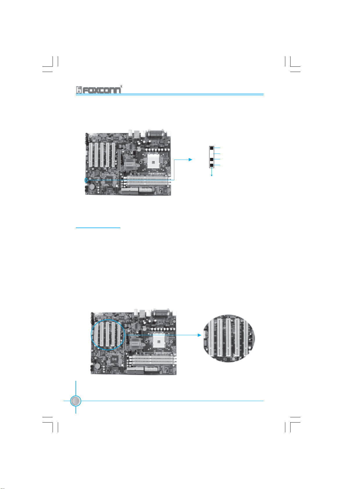
Expansion Slots
This motherboard includes five 32-bit Master PCI bus slots and one AGP slot.
PCI Slots
The expansion cards can be installed in the five PCI slots. When you install or
take out such cards, you must make sure that the power plug has been pulled
out. Please read carefully the instructions provided for such cards, and install
and set the necessary hardware and software for such cards, such as the
jumper or BIOS settings.
26
755A01-032604.p65 2004-3-26, 15:2826
755/760A01 Series User Manual
PCI Slots
Page 35

Chapter 2 Installation Instructions
AGP Slot
This motherboard has an AGP slot that supports 1.5V AGP cards. AGP is an
interfacing specification designed to display 3D images. It provides a specialized
66Mhz, 32-bit channel to allow the graphic controller to directly access the master
memory and supports 4X and 8X speeds.
AGP Slot
Installing an expansion card
1. Before installing the expansion card, read the documentation that came
with it and make the necessary hardware settings for the card.
2. Make sure to unplug the power cord before adding or removing expansion
cards.
3. Remove the bracket opposite the slot that you intend to use.
4. Align the card connector with the slot and press firmly until the card is
completely seated on the slot.
5. Secure the card to the chassis with the screw you removed earlier.
AGP Qualified Vendor List
The following table lists the AGP cards that have been tested and qualified for
use with this motherboard.
755/760A01 Series User Manual
755A01-032604.p65 2004-3-26, 15:2827
27
Page 36
Chapter 2 Installation Instructions
Vendor Type Video Memory
MSI MS-GeForce 4 MX440 8X 128MB
ATI ATI Radeon 7000 64MB
UNIKA 7917 GeForce 4 MX 440 64MB
CP ATI 9500 8X 128MB
CP ATI 9600 8X 128MB
ASUS V7100 8X 128MB
ASUS V7700 8X 128MB
Note:
Make sure to use only the tested and qualified AGP cards
listed above. Other AGP cards manufactured by other ven-
dors may not be suitable for this motherboard.
Jumpers
Users can change the jumper settings on this motherboard if needed. This
section explains how to use the various functions of this motherboard by changing the jumper settings. Users should read the following contents carefully prior
to modifying any jumper settings.
Description of Jumpers
1. For the jumpers on this motherboard, pin 1 can be identified by the silkscreen printed “ ” next to it. However, in this manual, pin 1 is simply
labeled as “1”.
2. The following table provides some explanation of the jumper pin settings.
Users should refer to this when adjusting jumper settings.
Jumper Diagram Definition Description
1
1
1
1
1
28
755A01-032604.p65 2004-3-26, 15:2828
1
755/760A01 Series User Manual
1-2 Set pin 1 and pin 2 closed
2-3 Set pin 2 and pin 3 closed
Closed Set the pin closed
Open Set the pin opened
Page 37
Chapter 2 Installation Instructions
Clear CMOS Jumper: CLS_CMOS
This motherboard uses the CMOS RAM to store all the set parameters. The
CMOS can be cleared by removing the CMOS jumper. How to clear CMOS?
1. Turn off the AC power supply and connect pins 1 and 2 together using the
jumper cap.
2. Return the jumper setting to normal (pins 2 and 3 locked together with the
jumper cap).
3. Turn the AC power supply back on.
Normal status
(default)
Clear CMOS
Clear CMOS Jumper
1
2
3
1
2
3
Warning:
1. Disconnect the power cable before adjusting the jumper
settings.
2. Do not clear the CMOS while the system is turned on.
755/760A01 Series User Manual
755A01-032604.p65 2004-3-26, 15:2829
29
Page 38
Chapter 2 Installation Instructions
BIOS-Protection Jumper: FWH_EN
The motherboard BIOS is inside the FWH. If the jumper FWH_EN is set as
disable (Pin1 & Pin2), the system BIOS is protected from being attacked by a
serious virus, such as the CIH virus. You will be unable to flash the BIOS to the
motherboard when the system BIOS is protected.
Flash Write
Enable
(Default)
Flash Write
Disable
BIOS-Protection Jumper
1
2
3
1
2
3
LAN Disable Jumper: LAN_DIS
This jumper is used to enable or disabled onboard LAN. Close pin 1 and 2, the
onboard LAN is enabled. Close pin 2 and 3, the onboard LAN is disabled.
LAN_DIS
1 2 3
Onboard LAN Enable
LAN_DIS
1 2 3
Onboard LAN Disable
30
755A01-032604.p65 2004-3-26, 15:2830
755/760A01 Series User Manual
Page 39

Chapter 2 Installation Instructions
Starting up for the first time
1. After making all the connections, replace the system case cover.
2. Be sure that all switches are off.
3. Turn on the devices in the following order.
a. Monitor
b. External SCSI devices (starting with the last device on the chain)
c. System power
4. After applying power, LED on the system front panel case lights up. For ATX
power supplies, the system LED lights up when you press the ATX power
switch. If your monitor complies with green standards or if it has a power
standby feature, the monitor LED may light up or switch between orange and
green after the system LED turns on. The system then runs the power-on
tests. While the tests are running, the BIOS beeps or additional mes
sages appear on the screen. If you do not see anything within 30 seconds
from the time you turned on the power, the system may have failed a power-
on test. Check the jumper settings and connections or call your retailer for
assistance.
5. At power on, hold down <Delete> to enter BIOS Setup. Follow the
instructions in Chapter 3.
Powering off the computer
1. Using the OS shut down function
If you use windows 98/ME/2000/XP, click the Start button, click Shut Down,
then click the OK button to shut down the computer. The power supply should
turnoff after Windows shuts down.
2. Using the dual function power switch
While the system is ON, pressing the power switch for less than 4
seconds puts the system to sleep mode or to soft-off mode, depending
on the BIOS setting. Pressing the power switch for more than 4 seconds
lets the system enter the soft-off mode regardless of the BIOS setting.
755/760A01 Series User Manual
755A01-032604.p65 2004-3-26, 15:2831
31
Page 40

Chapter
This chapter tells how to change system settings through the
BIOS Setup menus. Detailed descriptions of the BIOS param-
eters are also provided.
You have to run the Setup Program when the following cases
occur:
T-- This page is intentionally left blank --his
1. An error message appears on the screen during the
2. You want to change the default CMOS settings.
3
3
system POST process.
This chapter includes the following information:
Enter BIOS Setup
Main Menu
Standard CMOS Features
BIOS Features
Advanced BIOS Features Setup
Advanced Chipset Features Setup
Integrated Peripherals
Power Management Setup
PnP/PCI Configurations Setup
PC Health Status
Frequency/Voltage Control
Load Fail-Safe Defaults
Load Optimized Defaults
Set Supervisor/User Password
Save & Exit Setup
Exit Without Saving
755A01-032604.p65 2004-3-26, 15:2832
Page 41

Chapter 3 BIOS Description
Enter BIOS Setup
The BIOS is the communication bridge between hardware and software,
correctly setting up the BIOS parameters is critical to maintain optimal system
performance. Power on the computer, when the following message briefly
appears at the bottom of the screen during the POST (Power On Self Test),
press <Del> key to enter the Award BIOS CMOS Setup Utility.
Press TAB to show POST Screen, DEL to enter SETUP.
Note:
We do not suggest that you change the default parameters in the
BIOS Setup, and we shall not be responsible for any damage that
result from any changes that you make.
Main Menu
The main menu allows you to select from the list of setup functions and two exit
choices. Use the arrow keys to select among the items and press <Enter> to
accept or go to the sub-menu.
Main Menu
The items in the BIOS Setup main menu are explained below:
Standard CMOS Features
The basic system configuration can be set up through this menu.
BIOS Features
The general system features can be set up through this menu.
755/760A01 Series User Manual
755A01-032604.p65 2004-3-26, 15:2833
33
Page 42

Chapter 3 BIOS Description
Advanced BIOS Features
The advanced system features can be set up through this menu.
Advanced Chipset Features
The values for the chipset can be changed through this menu, and the sys-
tem performance can be optimized.
Integrated Peripherals
All onboard peripherals can be set up through this menu.
Power Management Setup
All the items of Green function features can be set up through this menu.
PnP/PCI Configurations
The system’s PnP/PCI settings and parameters can be modified through
this menu.
PC Health Status
This will display the current status of your PC.
Frequency/Voltage Control
Frequency and voltage settings can be adjusted through this menu.
Load Fail-Safe Defaults
The default BIOS settings can be loaded through this menu.
Load Optimized Defaults
The optimal performance settings can be loaded through this menu,
however, the stable default values may be affected.
Set Supervisor/User Password
The supervisor/user password can be set up through this menu.
Save & Exit Setup
Save CMOS value settings to CMOS and exit setup.
Exit Without Saving
Abandon all CMOS value changes and exit setup.
34
755A01-032604.p65 2004-3-26, 15:2834
755/760A01 Series User Manual
Page 43

Chapter 3 BIOS Description
Standard CMOS Features
This sub-menu is used to set up the standard CMOS features, such as the
date, time, HDD model and so on. Use the arrow keys select the item to set
up, and then use the <PgUp> or <PgDn> keys to choose the setting values.
Date
Standard CMOS Features Menu
This option allows you to set the desired date (usually as the current date)
with the <day><month><date><year> format.
day weekday from Sun. to Sat., defined by BIOS (read-only).
month month from Jan. to Dec.
date date from 1
st
to 31st, can be changed by using the keyboard.
year year,set up by users.
Time
This option allows you to set up the desired time (usually as the current time)
with <hour><minute><second> format.
IDE Channel 0/1 Master/Slave & Channel 2/3 Master
These categories identify the HDD types of 4 IDE channels installed in the
computer system. There are three choices provided for the Enhanced IDE BIOS:
None, Auto, and Manual. “None” means no HDD is installed or set; “Auto” means
the system can auto-detect the hard disk when booting up; by choosing “Manual”
and changing Access Mode to “CHS”, the related information should be entered
manually. Enter the information directly from the keyboard and press < Enter>:
Cylinder number of cylinders Head number of heads
Precomp write pre-compensation Landing Zone Landing Zone
Sector number of sectors
755/760A01 Series User Manual
755A01-032604.p65 2004-3-26, 15:2835
35
Page 44

Chapter 3 BIOS Description
Award (Phoenix) BIOS can support 4 HDD modes: CHS, LBA and Large or
Auto mode.
CHS For HDD<528MB
LBA For HDD>528MB & supporting LBA (Logical Block Addressing)
Large For HDD>528MB but not supporting LBA
Auto Recommended mode
Drive A/B
This option allows you to select the kind of FDD to be installed, including
“None”, [360K, 5.25in], [1.2M, 5.25in], [720K, 3.5in], [1.44M, 3.5in] and [2.88
M, 3.5in].
Video
The following table is provided for your reference in setting the display mode for
your system.
EGA/ VGA Enhanced Graphics Adapter / Video Graphic Array. For EGA,
VGA, SEGA, SVGA, or PGA monitor adapters.
CGA 40 Color Graphic Adapter, powering up in 40 column mode.
CGA 80 Color Graphic Adapter, powering up in 80 column mode.
MONO Monochrome adapter, including high resolution monochrome
adapters.
Halt On
This category determines whether or not the computer will stop if an error is
detected during powering up.
All Errors Whenever the BIOS detects a nonfatal error,the
system will stop and you will be prompted.
No Errors The system boot will not stop for any errors that may
be detected.
All, But Keyboard The system boot will not stop for a keyboard error;
but it will stop for all other errors.
All, But Diskette The system boot will not stop for a diskette error; but
it will stop for all other errors.
All, But Disk/Key The system boot will not stop for a keyboard or a
disk error,but it will stop for all other errors.
36
755A01-032604.p65 2004-3-26, 15:2836
755/760A01 Series User Manual
Page 45

Chapter 3 BIOS Description
Memory
This is a Displays-Only Category, detemined by POST(Power On Self Test)
of the BIOS.
Base Memory The BIOS POST will detemine the amount of base
(or conventional) memory installed in the system.
Extended Memory The BIOS determines how much extended
memory is present during the POST.
Total Memory Total memory of the system.
755/760A01 Series User Manual
755A01-032604.p65 2004-3-26, 15:2837
37
Page 46

Chapter 3 BIOS Description
BIOS Features
BIOS Features Menu
[SuperBoot] SuperBoot (Default: Disabled)
SuperBoot allows system-relevant information to be stored in CMOS upon
the first normal startup of your PC, and the relevant parameters will be
restored to help the system start up more quickly on each subsequent startup.
The available setting values are: Disabled and Enabled.
[SuperBIOS-Protect] SuperBIOS-Protect (Default: Disabled)
Super-BIOS Protect funtion protects your PC from being affected by viruses,
e.g. CIH. The available setting values are: Disabled and Enabled.
[SuperSpeed] CPU Clock (Depending on the specification of the CPU)
The conventional over-clock method uses the jumpers on the motherboard,
and it is both troublesome and apt to errors. By using SuperSpeed, a CPU
can be overclocked by keying in the desired in the CPU clock range.
[SuperRecovery] SuperRecovery Hotkey (Default: LSHIFT+F12)
SuperRecovery provides the users with an excellent data protection and
HDD recovery function. There are 12 optional settings, and the default
setting is LSHIFT+F12.
Warning:
Be sure your selection is right. CPU overclock will be dangerous!
We will not be responsible for any damage caused.
38
755A01-032604.p65 2004-3-26, 15:2838
755/760A01 Series User Manual
Page 47

Chapter 3 BIOS Description
Advanced BIOS Features
Advanced BIOS Features Menu
Hard Disk Boot Priority
This option is used to select the priority for HDD startup. After pressing
<Enter>, you can select the HDD using the <PageUp>/<PageDn> or Up/
Down arrow keys, and change the HDD priority using <+> or <->; you can
exit this menu by pressing <Esc>.
Virus Warning (Default: Disabled)
This option is used to set up the virus warning message for the IDE HDD
boot sector. When set to Enabled, a warning message will appear on the
screen if any program wants to write any information to this sector, and will
give an audible warning. The available setting values are: Disabled and
Enabled.
Note: Such function provides protection to the startup sector only; it does
not protect the entire hard disk.
CPU Internal Cache (Default: Enabled)
This option is used to turn on or off the CPU L1 and L2 cache. The
available setting values are: Disabled and Enabled.
External Cache (Default: Enabled)
This option is used to turn on or off the CPU external cache. The available
setting values are: Disabled and Enabled.
Quick Power On Self Test (Default: Enabled)
With this function enabled, the system will skip the normal test while
starting up, therefore reducing the overall start up time. The available
setting values are: Disabled and Enabled.
755/760A01 Series User Manual
755A01-032604.p65 2004-3-26, 15:2839
39
Page 48

Chapter 3 BIOS Description
First/Second/Third Boot Device (Default: Floppy/Hard Disk/CDROM)
This option allows you to set the boot device sequence. The available setting
values are: Floppy, LS120, Hard Disk, CDROM, ZIP100, USB-FDD, USB-ZIP,
USB-CDROM, LAN, and Disabled.
Boot Other Device (Default: Enabled)
With this function set to enabled, the system will boot from some other
devices if the first/second/third starting devices failed.
Swap Floppy Drive (Default: Disabled)
If it is set to enabled, the label of FDD A and B can be exchanged. The
available setting values are: Disabled and Enabled.
Boot Up Floppy Seek (Default: Enabled)
If it is set to enabled, BIOS will activate the floppy drive during the system boot,
and the drive’s indicator will flash after the activation. The magnetic head will
move back and forth from A to B. The available setting values are: Disabled
and Enabled.
Boot Up NumLock Status (Default: On)
This option is used to set up the NumLock status after the startup. When it is
set to On, the NumLock will be activated during system startup. When it is set
to off, users can use the number keys instead of the arrow keys to move the
cursor. The available setting values are: On and Off.
Gate A20 Option (Default: Fast)
This option is used to set up the A20 signal control necessary for access to
the 1MB memory. The available setting values are: Normal and Fast.
Typematic Rate Setting (Default: Disabled)
If this option is enabled, you can use the following two items to see the
typematic rate and the typematic delay settings for your keyboard. The available setting values are: Disabled and Enable.
Typematic Rate (Chars/Sec) (Default: 6)
Use this option to define how many characters per second a held-down key
generated.
Typematic Delay (Msec) (Default: 250)
Use this option to define how many milliseconds must elapse before a held-
down key beings generating repeat characters.
40
755A01-032604.p65 2004-3-26, 15:2840
755/760A01 Series User Manual
Page 49

Chapter 3 BIOS Description
Security Option (Default: Setup)
When it is set to setup, a password is required to enter the CMOS Setup
screen; when it is set to system, a password is required not only to enter
CMOS Setup, but also to startup your PC, as well.
APIC Mode (Default: Enabled)
This option is used to enable or disable APIC mode. The available setting
values are: Disabled and Enabled.
MPS Version Control For OS (Default: 1.4)
This option is used to set up the version of MPS Table used in NT4.0 OS.
OS Select For DRAM > 64MB (Default: Non-OS2)
This option is only required if you have installed more than 64 MB of memory
and you are running the OS/2 operating system. Otherwise, leave this option
at the default.
HDD S.M.A.R.T. Capability (Default: Disabled)
This option is used to enable or disable hard disk's S.M.A.R.T. support function.
The available setting values are: Disabled and Enabled.
Report No FDD For WIN 95 (Default: Yes)
If you are using the Windows 95 and running a system with on floppy drive,
select ”Yes” for this option to ensure compatibility with Windows 95 logo
certification. The available setting values are: No and Yes.
Video BIOS Shadow (Default: Enabled)
This option is used to enable or disable Video BIOS Shadow. If you enable
this option, the video BIOS will be copied to RAM. Video shadow will increase
the video speed. The available setting values are: Disabled and Enabled.
Full Screen LOGO Show (Default: Enabled)
This option allows you to enable or disable the full screen logo. The available
setting values are: Disabled and Enabled.
Small Logo (EPA) Show (Default: Disabled)
This option allows you to enable or disable the EPA logo. The available setting
values are: Disabled and Enabled.
755/760A01 Series User Manual
755A01-032604.p65 2004-3-26, 15:2841
41
Page 50

Chapter 3 BIOS Description
Advanced Chipset Features
Advanced Chipset Features Menu
DRAM Configuration (Default: Press Enter)
Press enter to set the items about DRAM Configuration. Please refer to
page 43.
AGP Aperture Size (Default: 64MB)
This option defines the size of the aperture if you use an AGP graphic
adapter. The aperture is a portion of the PCI memory address range dedi
cated for graphic memory address space.
Note: This function does not work when onboard VGA is used.
AGP Fast Write Support (Default: Disabled)
Use this option to enable or disable AGP fast write support.
AGP Data Transfer Rate (Default: Auto)
Use this option to set AGP data rate.
System BIOS Cacheable (Default: Disabled)
Select “Enabled” to allow catching of the system BIOS which may improve
performance. If any other program writes to this memory area, a system
error may result. The available setting values are: Disabled and Enabled.
42
755A01-032604.p65 2004-3-26, 15:2842
755/760A01 Series User Manual
Page 51
Chapter 3 BIOS Description
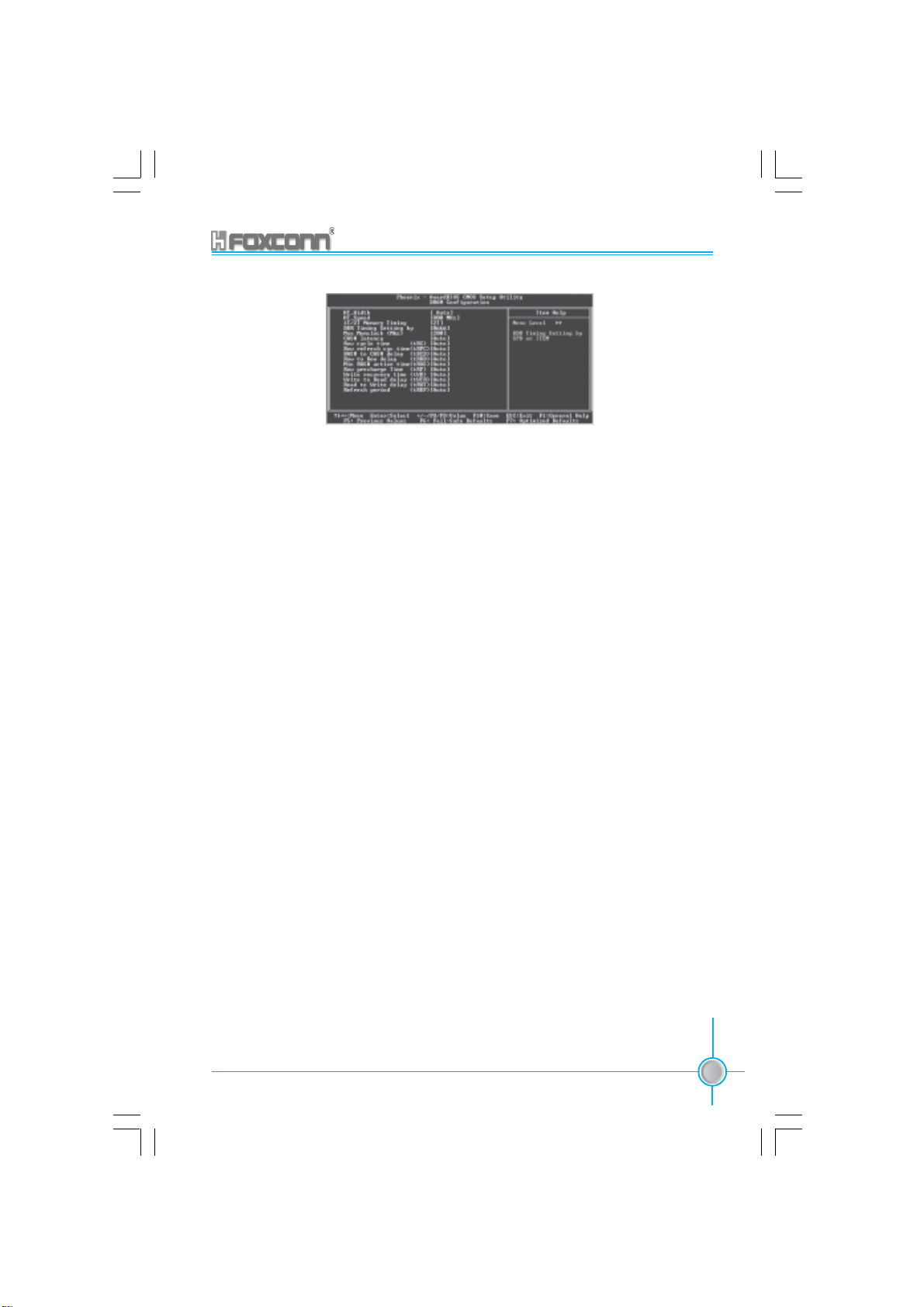
DRAM Configuration Menu
HT_Width (Default: Auto)
The available setting values are: 8 bits,16 bits and Auto.
HT_Speed(Default: 800MHz)
The available setting values are: 200MHz, 400 MHz, 600 MHz and 800 MHz.
1T/2T Memory Timing (Default: 2T)(Optional)
The available setting values are: Auto, 1T, 2T.
DDR Timing Setting by (Default: Auto)
The available setting values are: Manual and Auto.
Max Memclock (Mhz) (Default: 200)
The available setting values are: 100, 133, 166 and 200.
CAS# Latency (Default: Auto)
The available setting values are: CL=2.0, CL=2.5, CL=3.0 and Auto.
Row cycle time <tRC> (Default: Auto)
The available setting values are: Auto, 7 - 22 Bus Clocks.
Row refresh cyc time <tRFC> (Default: Auto)
The available setting values are: Auto, 9 - 24 Bus Clocks.
RAS# to CAS# delay <tRCD> (Default: Auto)
The available setting values are: Auto, 2 - 7 Bus Clocks.
755/760A01 Series User Manual
755A01-032604.p65 2004-3-26, 15:2843
43
Page 52

Chapter 3 BIOS Description
Row to Row delay <tRRD> (Default: Auto)
The available setting values are: Auto, 2 -7 Bus Clocks.
Min RAS# active time <tRAS> (Default: Auto)
The available setting values are: Auto, 5 -15 Bus Clocks.
Row precharge Time <tRP> (Default: Auto)
The available setting values are: Auto, 2 - 6 Bus Clocks.
Write recovery time <tWR> (Default: Auto)
The available setting values are: Auto, 2 - 3 Bus Clocks.
Write to Read delay <tWTR> (Default: Auto)
The available setting values are: Auto, 1 Bus Clock.
Read to Write delay <tRWT> (Default: Auto)
The available setting values are: Auto, 1 - 6 Bus Clocks .
Refresh period <tREF> (Default: Auto)
The available setting values are: Auto, 1x1552 Cycles - 4x4672 Cycles.
44
755A01-032604.p65 2004-3-26, 15:2844
755/760A01 Series User Manual
Page 53

Chapter 3 BIOS Description
Integrated Peripherals
Integrated Peripherals Menu
SIS OnChip IDE Device
Press enter to set onchip IDE device. Please refer to page 46.
SIS OnChip PCI Device
Press enter to set onchip PCI device. Please refer to page 47.
Onboard SuperIO Device
Press enter to set onchip onboard SuperIO device. Please refer to page 48.
IDE HDD Block Mode (Default:Enabled)
This option is used to set whether the IDE HDD Block Mode is allowed. The
available setting values are: Disabled and Enabled.
Init Display First (Default:PCI Slot)
This option is used to set which display device will be used first when your
PC starts up. The available setting values are: PCI Slot and AGP.
USB0/1/2/2.0 Access Interface (Default:EDB Bus)
This option is used to set USB0/1/2/2.0 Access Interface. The available
setting values are: PCI Bus and EDB Bus.
Audio Access Interface (Default:EDB Bus)
This option is used to set audio access Interface. The available setting
values are: PCI Bus and EDB Bus.
755/760A01 Series User Manual
755A01-032604.p65 2004-3-26, 15:2845
45
Page 54

Chapter 3 BIOS Description
SIS Onchip IDE Device Menu
Internal PCI/IDE (Default: Both)
This option is used to set the ports of onboard IDE. The available setting
values are: Disabled, Primary, Secondary and Both.
IDE Primary/Secondary Master/Slave PIO (Default: Auto)
These four items let you assign which kind of PIO(Programmer Input/Out
put) is used by IDE devices. Choose “Auto” to let the system auto detect
which PIO mode is the best or select a PIO mode from 0-4
Primary/Secondary Master/Slave UItraDMA (Default: Auto)
UItraDMA technology provides faster access to IDE devices.If you install a
device that supports UItraDMA, change the appropriate items on this list to
Auto. The available setting values are: Disabled and Auto.
IDE DMA transfer access (Default: Enabled)
This option is used to enable or disable IDE DMA transfer access.
IDE Burst Mode (Default: Enabled)
This option is used to enable or disable IDE burst mode.
46
755A01-032604.p65 2004-3-26, 15:2846
755/760A01 Series User Manual
Page 55

Chapter 3 BIOS Description
SIS OnChip PCI Device Menu
SIS USB Controller (Default: Enabled)
This option is used to enable or disable SIS USB controller.
USB 2.0 Supports (Default: Enabled)
This option is used to enable or disable USB 2.0.
USB Keyboard Support (Default: Enabled)
This option is used to set USB keyboard support. The available setting
values are: Disabled and Enabled.
USB Mouse Support (Default: Enabled)
This option is used to set USB mouse support. The available setting
values are: Disabled and Enabled.
SIS AC97 AUDIO (Default: Enabled)
This option is used to enable or disable SIS AC97 audio.
SIS S/W Modem (Default: Enabled)
This option is used to enable or disable CNR modem.
SIS Serial ATA Controller (Default: Enabled)
This option is used to enable or disable SIS serial ATA controller. The
available setting values are: Disabled and Enabled.
SIS Serial ATA Mode (Default: IDE)
This option is used to set Serial ATA mode. The default is recommended.
The available setting values are: IDE and RAID.
Lan Controller (Default: Enabled)
The available setting values are: Disabled and Enabled.
755/760A01 Series User Manual
755A01-032604.p65 2004-3-26, 15:2847
47
Page 56

Chapter 3 BIOS Description
Onboard Lan Boot ROM (Default: Disabled)
This option is used to decide whether to invoke the boot ROM of the onboard
LAN chip. The available setting values are: Disabled and Enabled.
Onboard SuperIO Device Menu
Onboard FDC Controller (Default: Enabled)
This option is used to set whether the onboard FDC controller is enabled.
The available setting values are: Disabled and Enabled.
Onboard Serial Port 1/2 (Default: 3F8/IRQ4/2F8/IRQ3)
This option is used to assign the I/O address and interrupt request(IRQ)
for the onboard serial port 1/2.
Note: Do not try to set the same values for serial port 1 and 2.
UART Mode Select (Default: Normal)
Use this option to select the UART mode. Setting values include Normal,
IrDA, ASKIR and SCR. The setting value is determined by the infrared mod
ule installed on the board.
UR2 Duplex Mode (Default: Half)
This option is available when UART 2 mode is set to either ASKIR or IRDA. This
option enables you to determine the infared function of the onboard infrared
chip. The available setting values are: Half and Full.
Onboard Parallel Port (Default: 378/IRQ7)
This option allows you to determine onboard parallel port controller I/O ad
dress and interrupt request(IRQ). Setting values include: Disabled, 378/IR
Q7, 278/IRQ5 and 3BC/IRQ7.
48
755A01-032604.p65 2004-3-26, 15:2848
755/760A01 Series User Manual
Page 57

Chapter 3 BIOS Description
Parallel Port Mode (Default: SPP)
Select an address amd corresponding interrupt for the onboard parallel port.
Setting values include SPP, EPP, ECP, ECP+EPP.
ECP Mode Use DMA (Default: 3)
Select a DMA channel for the parallel port when using the ECP mode.This field
is only configurable if Parallel Port Mode is set to ECP. The available setting
values are: 3 and 1.
755/760A01 Series User Manual
755A01-032604.p65 2004-3-26, 15:2849
49
Page 58

Chapter 3 BIOS Description
Power Management
Power Management Setup Menu
ACPI function (Default: Enabled)
ACPI stands for “Advanced Configuration and Power Interface”. ACPI is a
standard that defines power and configuration management interfaces between an operating system and the BIOS. In other words, it is a standard that
describes how computer components work together to manage system
hardware. In order to use this function the ACPI specification must be supported by the OS (for example, Windows2000 or WindowsXP). The available
setting values are: Enabled and Disabled.
ACPI Suspend Type (Default: S3(STR))
This option is used to set the energy saving mode of the ACPI function.
When you select “S1 (POS)” mode, the power will not shut off and the
supply status will remain as it is, in S1 mode the computer can beresumed
at any time. When you select “S3 (STR)” mode, the power will be cut off after
a delay period. The status of the computer before it enters STR will be saved
in memory, and the computer can quickly return to previous status when the
STR function wakes. When you select “S1 & S3” mode, the system will
automatically select the delay time.
Power Management (Default: User Define)
This option is used to set the power management scheme. Available settings
are: User Define, Min Saving and Max Saving.
Suspend Mode (Default: Disabled)
This option is used to set the idle time before the system enters into sleep
status. The setting values are Disabled and 1 Min-1 hour.
Video Off Option (Default: Susp, Stby - > Off)
This option is used to set video off option. The setting values are Always On,
Suspend -> Off, Susp,Stby - > Off, All Modes -> Off.
50
755A01-032604.p65 2004-3-26, 15:2850
755/760A01 Series User Manual
Page 59

Chapter 3 BIOS Description
Video Off Method (Default: DPMS Supported)
This option is used to define the video off method. “Blank Screen” mode
means that after the computer enters power saving mode, only the monitor
will close, however, the vertical and horizontal scanning movement of the screen
continues. When you select the “V/H SYNC + Blank” mode the vertical and horizontal
scanning movement of screen stops when the computer enters power saving
mode. “DPMS Supported” mode is a new screen power management system, and
it needs to be supported by the monitor you’re using.
Switch Function (Default: Break/Wake)
This option is used to enable or disable switch function to wake up. The
setting values are Break/Wake and disabled.
MODEM Use IRQ (Default: NA)
This option is used to set the IRQ in which the MODEM can use. The system
will automatically wake up when the Modem receives an incoming call.
Hot key Function As (Default:Power Off)
The option is used to define the hot key function. The available setting values
are Disabled, Power off, Suspend.
HDD Off After (Default: Disabled)
This option is used to define the continuous HDD idle time before the HDD
enters power saving mode. The setting values are Disabled and 1 Min -15 Min.
Power Button Override (Default: Instant Off)
This option is used to set the power down method. This function is only valid
for systems using an ATX power supply.
When “Instant Off” is selected, press the power switch to immediately turn off power.
When “Delay 4 Sec” is selected, press and hold the power button for four
seconds to turn off power.
Power State Resume control (Default: Always Off)
This option is used to control power resume state. The available setting val
ues are Always Off, Always On, Keep Pre-State.
PM Wake Up Events
Press enter to set the items of PM wake up Events. Please refer to page 52.
AMD K8 Cool&Quiet Control (Default: Auto)
This option is used to control AMD K8 Cool&Quiet function.
755/760A01 Series User Manual
755A01-032604.p65 2004-3-26, 15:2851
51
Page 60

Chapter 3 BIOS Description
PM Wake UP Events Menu
IRQ [3-7,9-15], NMI (Default: Enabled)
This option is used to enable or disable IRQ[3-7,9-15], NMI.
IRQ 8 Break Suspend (Default: Disabled)
This option is used to enable or disable IRQ8 break suspend.
RING Power Up Control (Default: Enabled)
If this option is enabled, it allows the system to resume from a software power
down or power saving mode whenever there is an incoming call to an installed fax/modem. This function needs to be supported by the relevant hardware and software. The setting values are: Disabled and Enabled.
PCIPME Power Up Control (Default: Enabled)
This option is used to enable or disable the system to be waken up by PCI
card.
PS2KB Wakeup from S3/S4/S5 (Default: Hot Key)
This option used to set which action will wake up PS/2 keyboard from S3/S4/
S5 status. The hotkey is Ctrl+Alt+Backspace. The setting values are Any Key,
Hot Key, Password.
PS2MS Wakeup from S3/S4/S5 (Default: Click)
This option used to set which action will wake up PS/2 mouse from S3/S4/S5
status. The setting values are: Disabled, Click, Move & Click.
Power UP by Alarm (Default: Disabled)
This option is used to set the timing of the start-up function. In order to use this
function, the start-up password function must be canceled. Also, the PC power
source must not be turned off. The setting values are: Disabled and Enabled.
Month Alarm
This option is used to set the timing for the start-up month. The setting values
contain 1 - 12 and NA.
52
755A01-032604.p65 2004-3-26, 15:2852
755/760A01 Series User Manual
Page 61

Chapter 3 BIOS Description
Day of Month Alarm
This option is used to set the timing for the start-up day of the month. The setting
values contain 0 - 31.
Time (hh:mm:ss) Alarm
This option is used to set the timing for the start-up time. The setting values
contain hh:0 – 23; mm:0 – 59; ss:0 – 59.
Primary/Secondary IDE (Default: Disabled)
When these items are enabled, the system will restart the power saving timeout
counters when any activity is detected on any of the drives or devices on the
primary or secondary IDE channels. The setting values are Disabled and
Enabled.
FDD, COM, LPT Port (Default: Disabled)
When this option is enabled, the system will restart the power saving timeout
counters when any activity is detected on the floppy disk drive, serial ports, or
the parallel port.
PCI PIRQ [A-D]# (Default: Disabled)
When this option is disabled, any PCI devices set as the master will not power
on the system.
755/760A01 Series User Manual
755A01-032604.p65 2004-3-26, 15:2853
53
Page 62

Chapter 3 BIOS Description
PnP/PCI Configurations
PnP/PCI Configurations Menu
Reset Configuration Data (Default: Disabled)
This option is used to set whether the system is permitted to automatically
distribute IRQ DMA and I/O addresses when each time the machine is turned
on. The setting values are: Disabled and Enabled.
Resources Controlled By (Default: Auto (ESCD))
This option is used to define the system resource control scheme. If all cards
you use support PnP, then select Auto (ESCD) and the BIOS will automatically
distributes interruption resources. If the ISA cards you installed not supporting PnP, you will need to select “Manual” and manually adjust interruption
resources in the event of hardware conflicts. However, since this motherboard
has no ISA slot, this option does not apply.
IRQ Resources
Press the <Enter> key, then manually set IRQ resources.
PCI/VGA Palette Snoop (Default: Disabled)
If you use a non-standard VGA card, use this option to solve graphic acceleration card or MPEG audio card problems (e.g., colors not accurately displayed).
The setting values are: Disabled and Enabled.
Raid Card Boot First (Default: Disabled)
This option is used to set Raid card boot first. The setting values are: Dis-
abled and Enabled
54
755A01-032604.p65 2004-3-26, 15:2854
755/760A01 Series User Manual
Page 63

Chapter 3 BIOS Description
PC Health Status
PC Health Status Menu
Smart Fan Control (Default: Disabled)
This option is used to control the smart fan.
Shutdown Temperature (Default: Disabled)
This option is used to set the system temperature upper limit. When the
temperature exceeds the setting value, the motherboard will automatically cut
off power to the computer. The setting values are: 60
o
C/158oF, Disabled.
70
Vccp/ +3.3v/+5v/+12v
The current voltages will be automatically detected by the system.
o
C/140oF, 65oC/149oF,
CPU Temp
The current CPU temperature will be automatically detected by the system.
System Temp1
The system temperature1 will be automatically detected by the system.
System Temp2
The system temperature2 will be automatically detected by the system.
CPU FAN Speed
The CPU fan speed will be automatically detected by the system.
System FAN1 Speed
The system fan1 speed will be automatically detected by the system.
755/760A01 Series User Manual
755A01-032604.p65 2004-3-26, 15:2855
55
Page 64

Chapter 3 BIOS Description
Frequency/Voltage Control
Frequency/Voltage Control Menu
Auto Detect PCI Clk (Default: Enabled)
This option is used to set whether the clock of an unused PCI slot will be
disabled to reduce electromagnetic interference. The setting values are Dis-
abled and Enabled.
Async SRC/ZCLK/AGP/PCI (Default:Disabled )
The setting values are: 100/133/66/33Mhz, 100/150/75/37Mhz, 100/133/80/
40Mhz and Disabled.
Spread Spectrum (Default: Disabled)
If you enable spread spectrum, it can significantly reduce the EMI (ElectroMagne
tic Interference) generated by the system.
56
755A01-032604.p65 2004-3-26, 15:2856
755/760A01 Series User Manual
Page 65

Chapter 3 BIOS Description
Load Fail-Safe Defaults
Select this option to press Enter, it will pop out a dialogue box to allow you to
load default set by BIOS. Select <Y> and then press Enter to load default. Select
<N> and press Enter, it will not load. The defaults set by BIOS have set the basic
functions of system in order to ensure the stability of system. But if your computer fails to properly run, you may load the default to make the system recover
normal, then carry out failure testing in next step. If you only want to load the
default in an option, you can select this option and press the key F6.
Load Optimized Defaults
Select this option and press Enter, it will pop out a dialogue box to let you load
the optimized defaults set by BIOS. Select <Y> and then press Enter to load the
optimized defaults. Select <N> and press Enter, it will not load. The defaults set
by BIOS have set the optimized performance parameters of system to improve
the performances of system components. But if the optimized performance
parameters to be set cannot be supported by your hardware devices, it will
cause system to make mistakes or not stable. If you only want to load the
optimized defaults in an option, you can select this option and press the key F7.
Set Supervisor/User Password
The preferential grade of supervisor password is higher than user password.
You can use supervisor password to start into system or enter into CMOS setting program to amend setting. You can also use user password to start into
system, or enter into CMOS setting menu to check, but if you have set supervisor
password, you cannot amend setting.
When you select Set Supervisor / User Password, it will appear the following
message in the center of screen, which will help you to set password.
Enter Password:
Enter your password, not exceeding 8 characters, then press <Enter>, the password you have been enter now will replace the previous password. When the
system requires you to determine this password, you can enter this password
and press <Enter>.
If you do not need this setting, you can press <Enter> when the screen prompts
you to enter password, and the screen will appear the following message to
show this function invalid. In this case, you can freely enter into system and
CMOS setting program.
PASS WORD DISABLED!!!
Press any key to continue...
755/760A01 Series User Manual
755A01-032604.p65 2004-3-26, 15:2857
57
Page 66

Chapter 3 BIOS Description
Under the menu “Advanced BIOS Features Setup”, if you select “System” in
Security Option, the screen will prompt you to enter password once the system
is started or you want to enter CMOS setting program. If the password is wrong,
it will refuse you to continue.
Under the menu “Advanced BIOS Features Setup”, if you select “Setup” in Security Option, the screen will prompt you to enter password only when you enter
CMOS setting program.
Save & Exit Setup
Select this option and press Enter, it will show the following message in the
center of screen:
SAVE to CMOS and EXIT (Y/N)?
At this time, press <Y> to save your amendment in CMOS and exit from this
program; press <N>/<ESC> to return main menu.
Exit Without Saving
Select this option and press Enter, it will show the following message in the
center of screen:
Quit Without Saving (Y/N)?
At this time, press <Y> to exit CMOS but it does not save your amendment in
CMOS; press <N>/<ESC> to return main menu.
58
755A01-032604.p65 2004-3-26, 15:2858
755/760A01 Series User Manual
Page 67

Chapter
The utility CD that came with the motherboard contains useful
software and several utility drivers that enhance the mother-
board features.
This chapter includes the following information:
4
4
Utility CD content
Start to install drivers
Install IDE Driver
Install SiS SATA RAID
Install AGP Driver
Install Direct X 9.0b
Install USB2.0 Driver
Using 4-/6-Channel Audio
Install LAN Driver
Install SiI3112 SATA RAID
Install SuperUtility
Install Adobe Reader
Install Norton Internet Security 2004
755A01-032604.p65 2004-3-26, 15:2859
Page 68
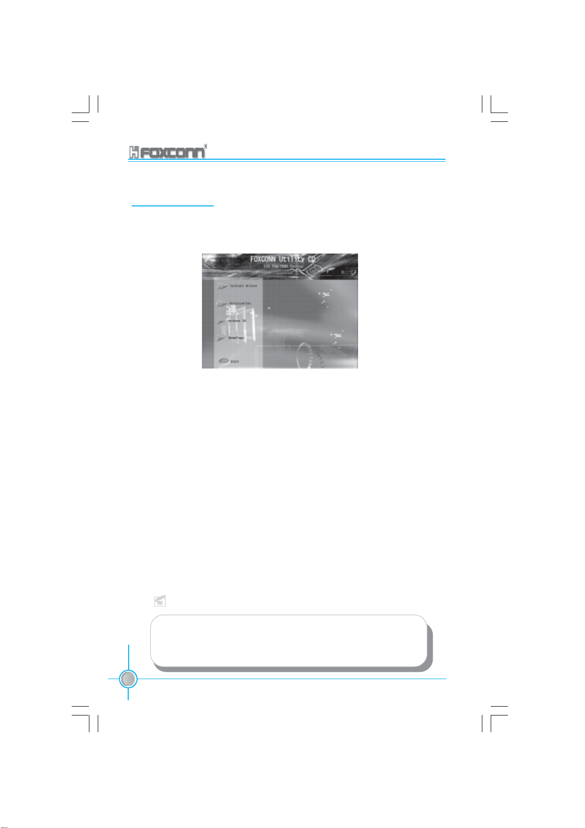
Chapter 4 Driver CD Introduction
Utility CD content
This motherboard comes with one Utility CD. To begin using the CD, simply
insert the CD into your CD-ROM driver. The CD will automatically display the
main menu screen.
1. Install Driver
Using this option to install all the drivers for your motherboard. You should
install the drivers sequentially, from first to last.
A. IDE Driver B. SiS SATA RAID
C. AGP Driver D. Direct X 9.0b
E. USB 2.0 Driver F. Audio Driver
G. LAN Driver H. Sil3112 SATA RAID
2.Accessories
Use this option to install additional software programs.
A. SuperUtility B. Adobe Reader
C. Norton Internet Security 2004
3. Browse CD
Click to browse this CD.
4. Homepage
Click here to visit Foxconn motherboard homepage.
Note:
1. Install the latest patch first if your OS is Windows XP or Win-
dows 2000.
2. Follow the CD screen order to install your motherboard drivers.
60
755A01-032604.p65 2004-3-26, 15:2860
755/760A01 Series User Manual
Page 69

Chapter 4 Driver CD Introduction
Start to Install divers
Select <Install Driver>, and click to enter the install driver screen. You can select
the driver that you want to install and begin the setup steps.
Note:
The following setup steps are based on Windows XP
environment. There may be some differences with other operat-
ing systems.
Install IDE Driver
Click <Install Driver> from the main menu and enter the install driver menu (as
shown in fig. 1). Click <IDE Driver> to start the installation.
755/760A01 Series User Manual
755A01-032604.p65 2004-3-26, 15:2861
Click here
1
61
Page 70

Chapter 4 Driver CD Introduction
Install SiS SATA RAID
Click <Install Driver> from the main menu and enter the install driver menu (as
shown in fig.1). Click<SiS SATA RAID> to start the installation.
Click here
1
Install AGP Driver
Click <Install Driver> from the main menu and enter the install driver menu (as
shown in fig. 1). Click <AGP Driver> to start the installation.
62
755A01-032604.p65 2004-3-26, 15:2862
755/760A01 Series User Manual
Click here
1
Page 71

Chapter 4 Driver CD Introduction
Install DirectX 9.0b
Click <Install Driver> from the main menu and enter the install driver menu (as
shown in fig. 1). Click <DirectX 9.0b> to start the installation.
Click here
1
Install USB 2.0 Driver
Click <Install Driver> from the main menu and enter the install driver menu (as
shown in fig. 1). Click <USB 2.0 Driver> to open the USB 2.0 Installation guide.
Please read the guide carefully and select the relevant installation method.
755/760A01 Series User Manual
755A01-032604.p65 2004-3-26, 15:2863
Read this guide carefully
1
63
Page 72

Chapter 4 Driver CD Introduction
Using 4-/6-Channel Audio
The motherboard is equipped with the Realtek ALC655 chip, which provides
support for 6-Channel audio output, including 2 front, 2 rear, 1 center and 1
subwoofer channel. ALC655 allows the board to attach 4 or 6 speakers for a
better surround sound effect. This section will tell you how to install and use the
4-/6-Channel audio function on the board.
Installing the Audio Driver
You need to install the driver for the Realtek ALC655 chip before you can use the
4-/6-Channel audio function.
Click <Install Driver> from the main menu and enter the install driver menu (as
shown in fig. 1). Click <Audio Driver> to start the installation.
64
755A01-032604.p65 2004-3-26, 15:2864
755/760A01 Series User Manual
Click here
1
Page 73
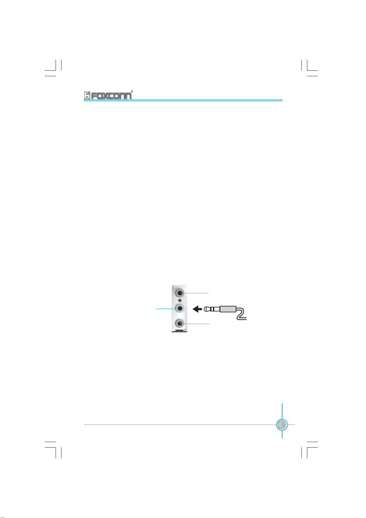
Chapter 4 Driver CD Introduction
Attaching Speakers
To perform multichannel audio operation, connect multiple speakers to the
system. You should connect the same number of speakers as the audio chan-
nels you will select in the software utility.
2-Channel Analog Audio Output
The audio connectors on the rear panel already provide 2-Channel analog au-
dio output. The rear panel’s audio connectors can be transformed to 4-/6-Chan-
nel analog audio connectors automatically when you select the correct setting
in the software utility. For information about the setting, refer to Selecting 4- or 6-
Channel Setting later in this section.
Make sure all speakers are connected to Line-out connectors. Diverse connec-
tor configurations for 2-, 4- and 6-Channel using rear panel connectors are
described below:
2-Channel Analog Audio Output
Line-in
Line-out (Front channels)
MIC
Description: Line-out, Line-in and Microphone functions all exist under 2-Channel
configuration.
755/760A01 Series User Manual
755A01-032604.p65 2004-3-26, 15:2865
65
Page 74

Chapter 4 Driver CD Introduction
4-Channel Analog Audio Output
Line-out (Rear channels)
Line-out (Front channels)
MIC
Description: Line-in is converted to Line-out under the 4-Channel configuration.
6-Channel Analog Audio Output
Line-out (Rear channels)
Line-out (Front channels)
Line-out
(Center and Subwoofer channels)
Description: Both Line-in and Microphone are converted to Line-out under the 6-Chan-
nel configuration.
66
755A01-032604.p65 2004-3-26, 15:2866
755/760A01 Series User Manual
Page 75

Digital Audio Output
Chapter 4 Driver CD Introduction
S/PDIF Cable
Or
Coaxial S/PDIF jack
Description: Connect the S/PDIF speakers to the Coaxial S/PDIF jack.
6CH_Bracket
Selecting 4- or 6-Channel Setting
1. Click the audio icon from the Windows tray bar at the bottom of the
screen.
2. Select any surround sound effect you prefer from the “Environment” pull-
down menu under the Sound Effect tab.
755/760A01 Series User Manual
755A01-032604.p65 2004-3-26, 15:2867
Click here and the
pull-down menu
will appear.
67
Page 76

3. Click the Speaker Configuration tab.
4. The following window appears.
Chapter 4 Driver CD Introduction
Click here
5. Select the multi-Channel operation you prefer from Number of Speakers.
6. Click OK.
68
755A01-032604.p65 2004-3-26, 15:2868
755/760A01 Series User Manual
Click here
Page 77

Chapter 4 Driver CD Introduction
Testing the Connected Speakers
To ensure 4- or 6-Channel audio operation works properly, you may need to test
each connected speaker to make sure every speaker works properly. If any
speaker fails to sound, then check whether the cable is inserted firmly to the
connector or replace the bad speakers with good ones.
Testing Each Speaker
1. Click the audio icon
screen.
2. Click the Speaker Test tab.
3. The following window appears.
from the window tray bar at the bottom of the
Front Left
Rear Left Rear Right
Subwoofer
Center
Front Right
4. Select the speaker which you want to test by clicking on it.
Playing Karaoke
The Karaoke function will automatically remove human voice (lyrics) and leave
melody for you to sing the song. The function can only be used with the 2-
Channel audio configuration, so make sure “2 channels mode” is selected in
the “Number of Speakers” column before playing Karaoke.
Playing Karaoke
1. Click the audio icon
from the window tray at the bottom of the screen.
2. Make sure the Sound Effect tab is selected.
3. Select Voice Cancellation in the “Karaoke” column.
755/760A01 Series User Manual
755A01-032604.p65 2004-3-26, 15:2869
69
Page 78

Chapter 4 Driver CD Introduction
Click here
4. Click OK.
Install LAN Driver
Click <Install Driver> from the main menu and enter the install driver menu (as
shown in fig. 1). Click <LAN Driver> to start the installation.
70
755A01-032604.p65 2004-3-26, 15:2870
755/760A01 Series User Manual
Click here
1
Page 79

Chapter 4 Driver CD Introduction
Install SiI3112 SATA RAID Driver
Click <Install Driver> from the main menu and enter the install driver menu (as
shown in fig. 1). Click <SiI3112 SATA RAID> to start the installation.
Click here
1
Install SuperUtilily
From the main menu, select <Accessories> (as shown in following fig. 1). Click
<SuperUtilily> to start the setup.
755/760A01 Series User Manual
755A01-032604.p65 2004-3-26, 15:2871
Click here
1
71
Page 80
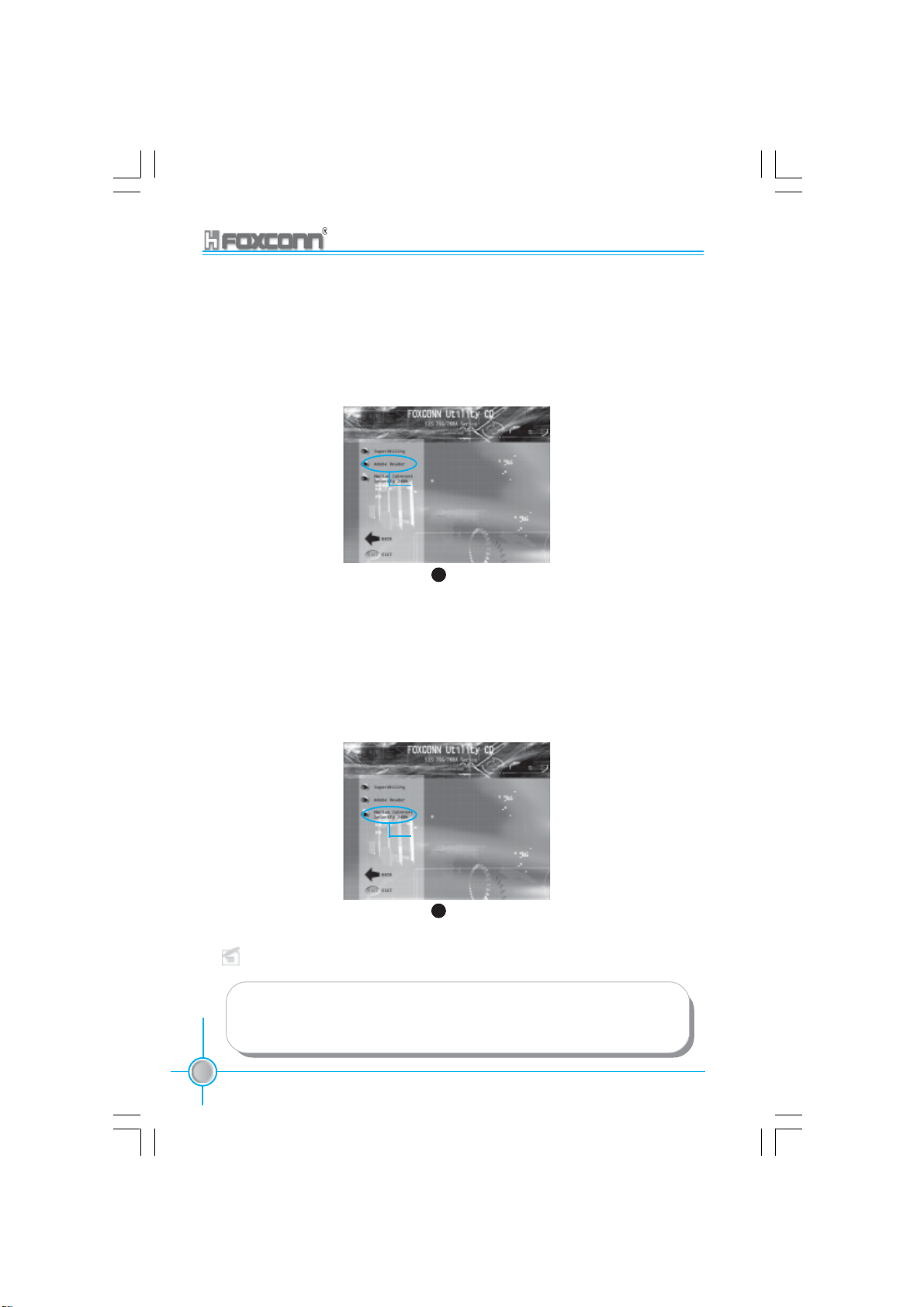
Chapter 4 Driver CD Introduction
Install Adobe Reader
From the main menu, select <Accessories> (as shown in following fig. 1). Click
<Adobe Reader> to start the setup.
Click here
1
Install Norton Internet Security 2004
From the main menu, select <Accessories> (as shown in following fig. 1).
Click <Norton Internet Security 2004> to start the setup.
Note:
If your system is Windows 98 or Windows ME, please make sure that
your Internet Explorer version is 5.01 with service pack 2 or higher.
72
755A01-032604.p65 2004-3-26, 15:2872
755/760A01 Series User Manual
Click here
1
Page 81

Chapter
This chapter will introduce how to use attached software.
Chapter 4 Driver CD Introduction
5
5
This chapter includes the following information:
SuperStep
SuperUpdate
SuperLogo
755/760A01 Series User Manual
755A01-032604.p65 2004-3-26, 15:2873
73
Page 82
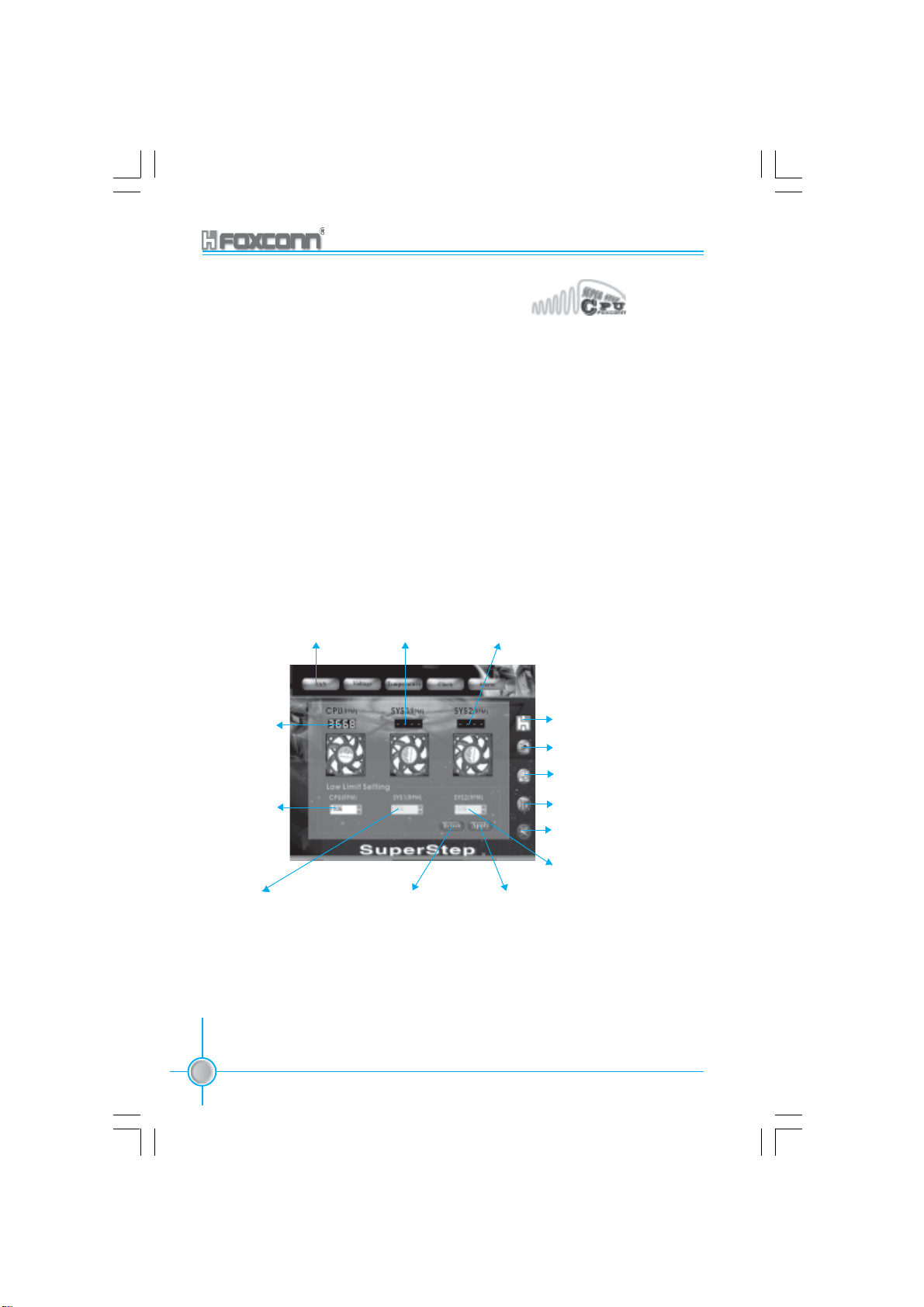
Chapter 5 Directions for Bundled Software
SuperStep
SuperStep is a utility that allows users to change the frequency of the CPU. It also
displays system health introduction including CPU temperature, CPU voltage,
and PCI/AGP clock.
SuperStep features:
1. Supports Win98SE, WinME, Win2000 and WinXP.
2. Automatic alarm mechanism when system runs irregularly
3. Adjusts the CPU frequency to speed up your system and achieve better system
performance.
4. Simple and easy to operate, with a user-friendly graphics interface.
Using SuperStep:
CPU Fan
speed
Adjust CPU
Fan warning
criteria
Adjust system
Fan1 warning
criteria
Go to Fan
page
System Fan1
speed
Reset the
warning criteria
to default
settings
System Fan2
speed (optional)
Link to Foxconn Website
Exit Program
Minimize Window
SuperStep on-line Help
About SuperStep
Adjust system Fan2
warning criteria
Apply the
adjustments
74
755A01-032604.p65 2004-3-26, 15:2874
755/760A01 Series User Manual
Page 83

Chapter 5 Directions for Bundled Software
Current voltage
readings
Go to Voltage
page
Reset the warning
criteria to default
settings
Go to Temperature page
Adjust voltages warning
criteria (upper limit)
Apply the
adjustments
Adjust voltages
warning criteria
(Lower limit)
Current CPU
Temperature
Current system
Temperature
Reset the warning criteria to
default settings
755/760A01 Series User Manual
755A01-032604.p65 2004-3-26, 15:2875
Adjust CPU temperature warning
criteria
Adjust system
temperature
warning criteria
Apply the adjustments
75
Page 84
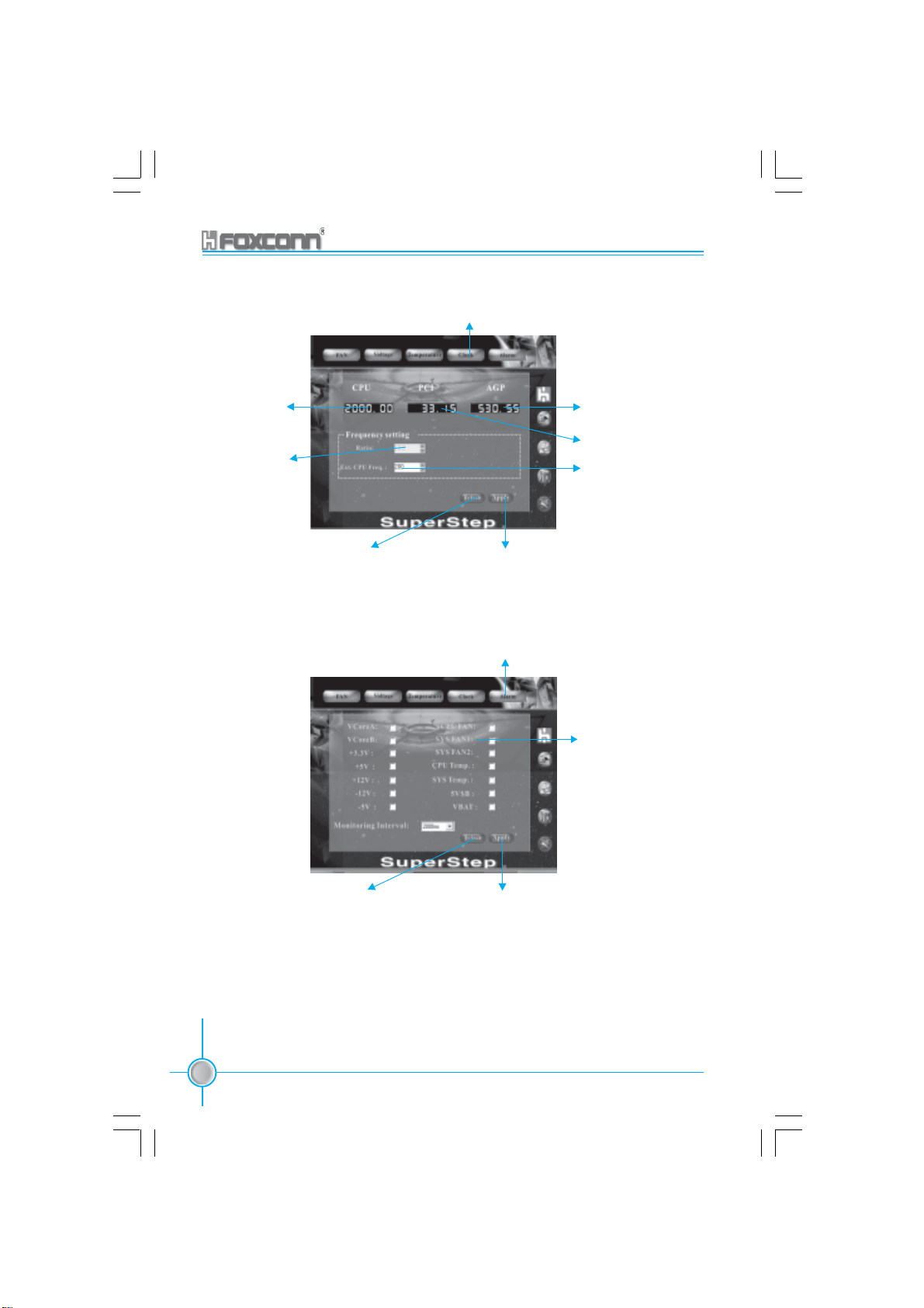
Chapter 5 Directions for Bundled Software
Go to Clock
page
Current CPU
Clock
Adjust the
CPU Ratio
Reset to the default
settings
Current AGP clock
Current PCI clock
Adjust the CPU
FSB
Apply the adjustments
Go to Alarm
page
Check for the
system to automatically provide
warning message
Reset to the
default settings
76
755A01-032604.p65 2004-3-26, 15:2876
755/760A01 Series User Manual
Apply the
changes
Page 85
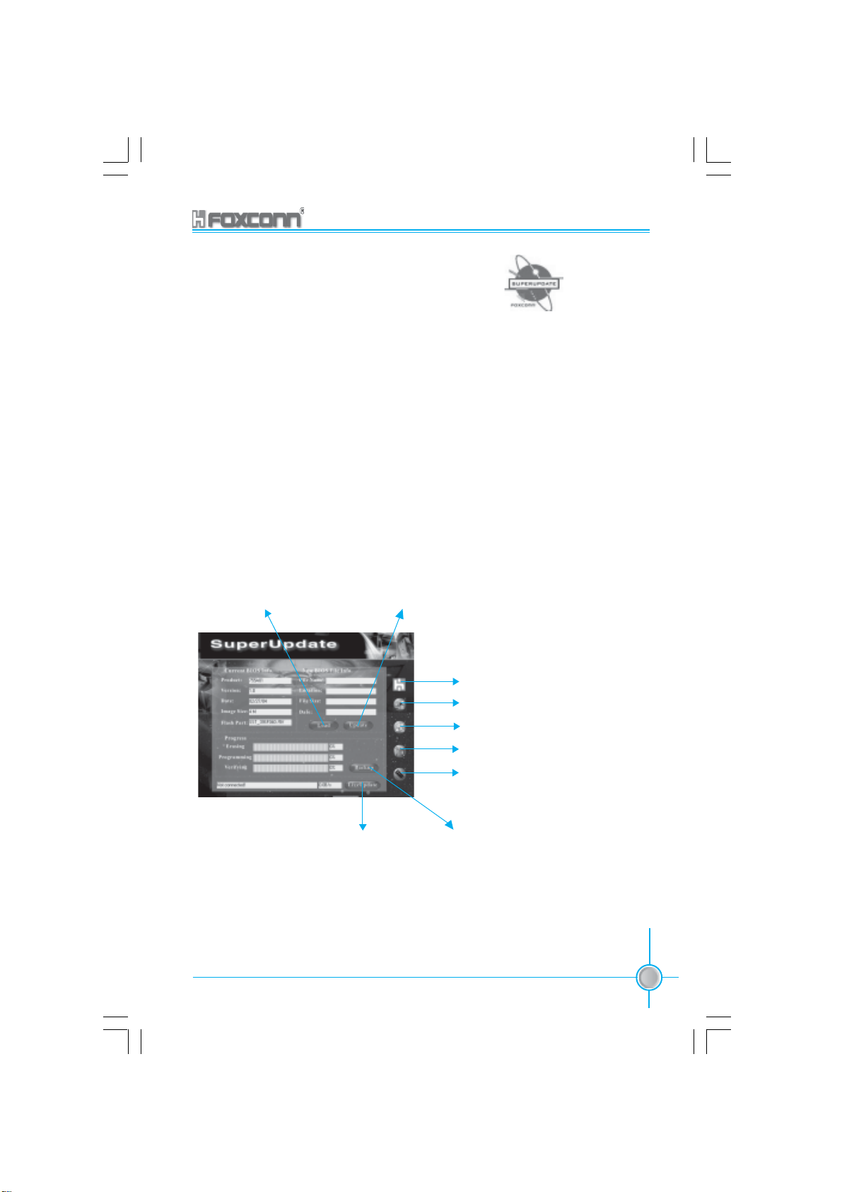
Chapter 5 Directions for Bundled Software
SuperUpdate
SuperUpdate is a Windows utility that allows users to backup and upgrade the
system BIOS.
SuperUpdate features:
1.Supports Win2000 and WinXP.
2.Supports 4MB size flash parts; flash write method is independent of flash
type.
3.Simple and easy to operate, with a user-friendly graphics interface.
Using SuperUpdate:
Browse BIOS bin file
from local HDD
Upgrating BIOS via
internet automatically
755/760A01 Series User Manual
Perform the BIOS update
from local image
Link to Foxconn Website
Exit Program
Minimize Window
SuperUpdate on-line Help
About SuperUpdate
Backup system
BIOS to an image
file
77
755A01-032604.p65 2004-3-26, 15:2877
Page 86
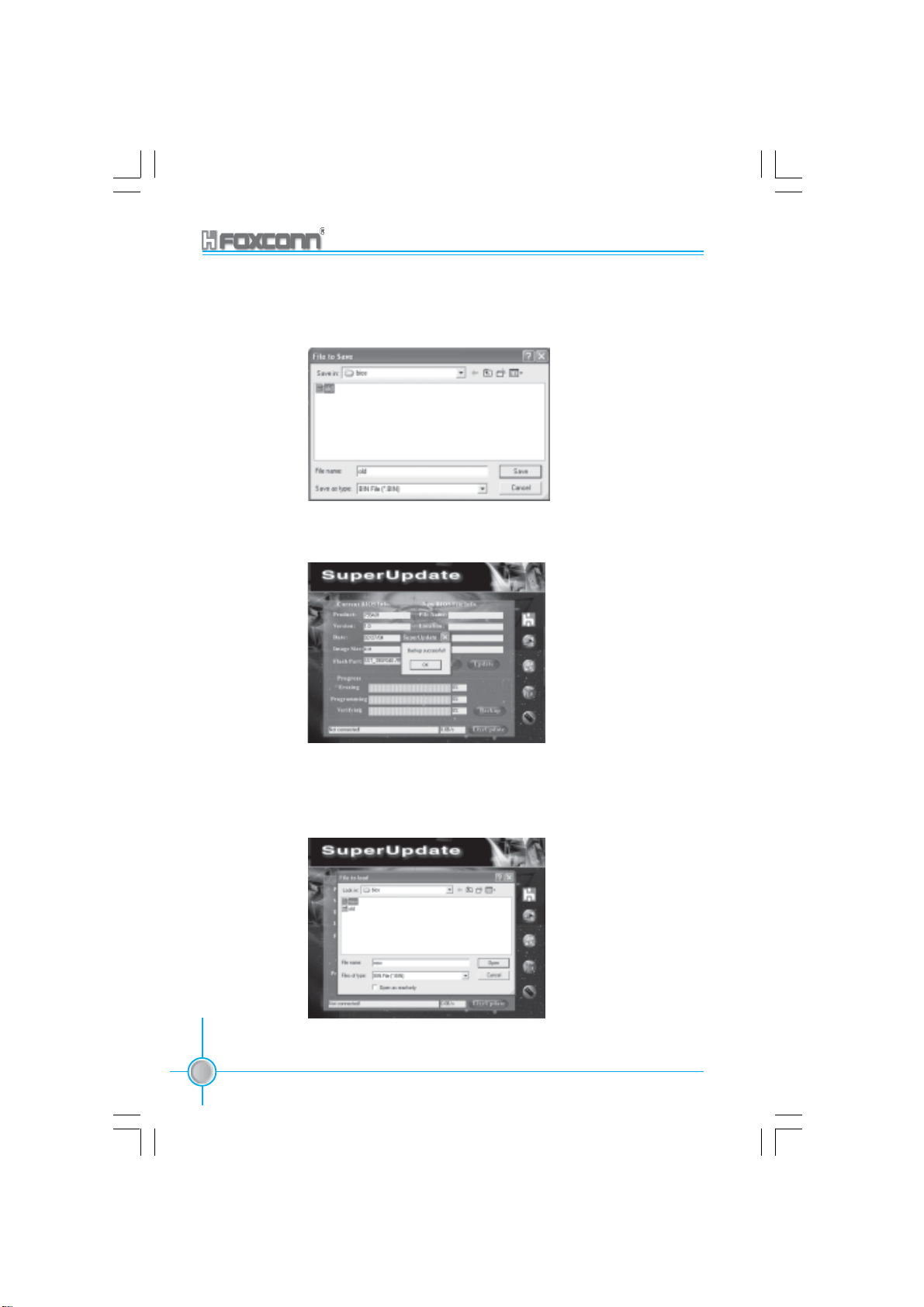
Chapter 5 Directions for Bundled Software
Bakeup BIOS to local image:
1. Click <Backup> to backup current BIOS file.
2. Click <OK> to finish the backup process.
Update BIOS from local image:
1. Click <Load> to load the BIOS file.
78
755A01-032604.p65 2004-3-26, 15:2878
755/760A01 Series User Manual
Page 87
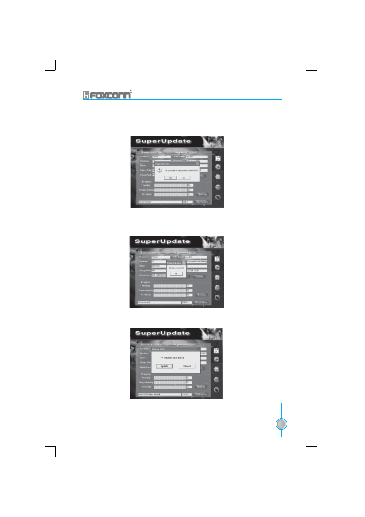
Chapter 5 Directions for Bundled Software
2. Click <Update>, the following message will appear.
3. Click <Yes> to backup the current BIOS, then the following picture will
appear.
4. Click <OK >, then click <Update>.
755/760A01 Series User Manual
755A01-032604.p65 2004-3-26, 15:2879
79
Page 88
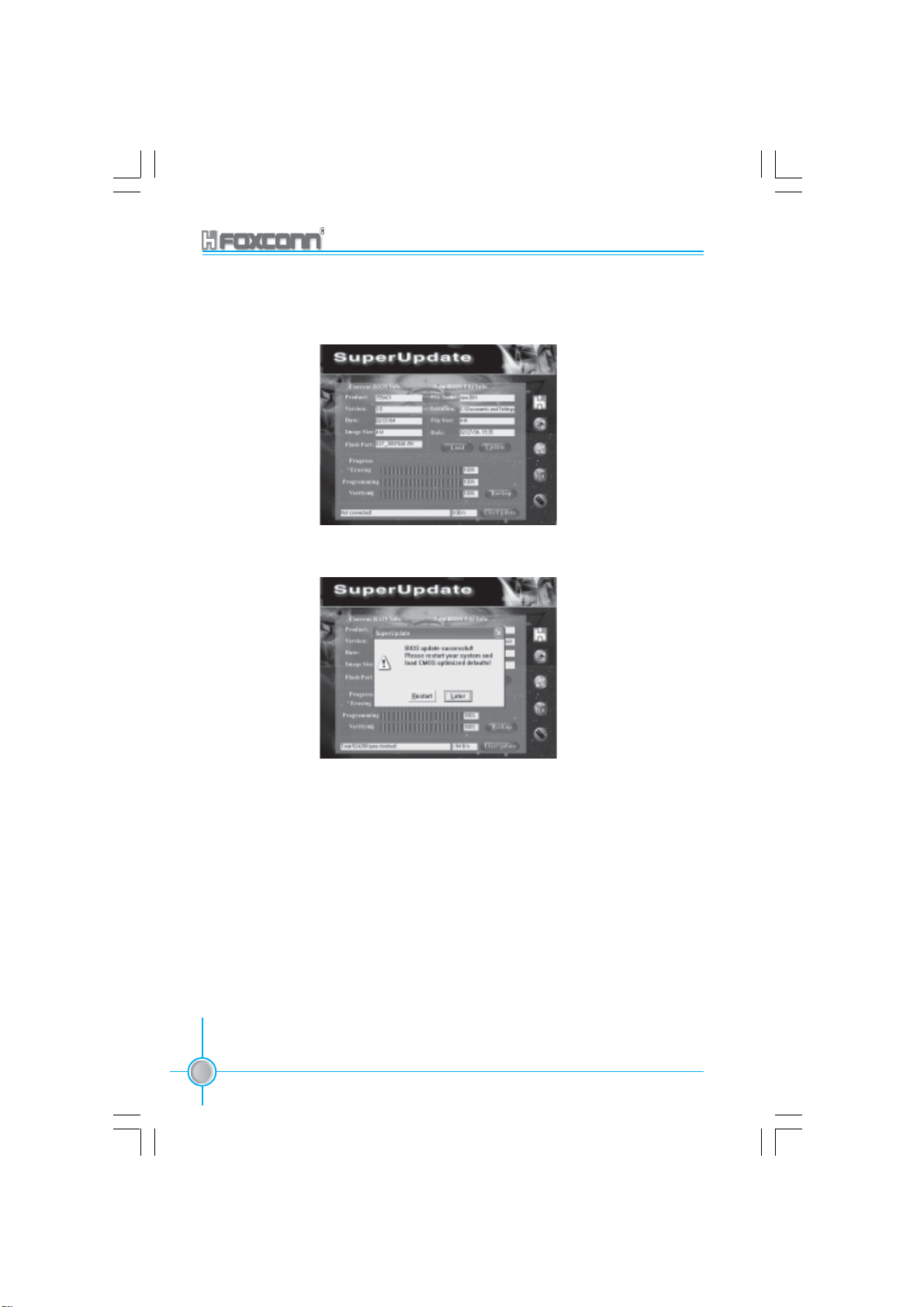
5. Now is updating.
6. Click <Restart>.
Chapter 5 Directions for Bundled Software
80
755A01-032604.p65 2004-3-26, 15:2880
755/760A01 Series User Manual
Page 89

Chapter 5 Directions for Bundled Software
Update BIOS On-line:
1. Click <Liveupdate> to automatically update the BIOS from the internet.
2. The following procedure is the same as Update BIOS from local image.
755/760A01 Series User Manual
755A01-032604.p65 2004-3-26, 15:2881
81
Page 90

Chapter 5 Directions for Bundled Software
SuperLogo
SuperLogo is a Windows utility that allows users to change the BIOS sign on
logo. The utility is able to replace and backup the BIOS logo, and update and
backup the BIOS image within the Windows environment.
SuperLogo features:
1. Supports Win2000 and WinXP.
2. Supports 4Mb size flash parts, flash write method is independent with flash
type.
3. Simple and easy to operate, with a user-friendly graphics interface.
4. Supports BMP and JPEG graphic format files. The best color is 16 or 256
colors. The best resolution is 136 x 84 for top-right logo and 640 x 480 or 800
x 600 for full screen logo.
Using SuperLogo:
Go to ROM Info. page
82
755A01-032604.p65 2004-3-26, 15:2882
755/760A01 Series User Manual
Display the Flash Information
Link to Foxconn website
Exit Program
Minimize Window
SuperLogo On-Line Help
About SuperLogo
Page 91

Full screen mode
Top-Right mode
Chapter 5 Directions for Bundled Software
Go to Change Logo page
Boot without logo
BIOS image
file location
Follow the
Wizard to
complete the
logo update
Go to Update BIOS page
Browse a BIN file
for updating BIOS
Follow the Wizard
to complete the
BIOS function
Go to Backup page
Backup whole
BIOS image
755/760A01 Series User Manual
755A01-032604.p65 2004-3-26, 15:2883
Backup Logo
Follow the Wizard
to complete the
backup function
83
Page 92

Chapter
This chapter will introduce new functions of BIOS and how to
use them in detail. It can further exert the max potential of
motherboard to bring you super-value enjoyment.
This chapter introduces the following new functions of BIOS:
Chapter 5 Directions for Bundled Software
6
6
SuperBoot
SuperBIOS-Protect
SuperSpeed
SuperRecovery
84
755A01-032604.p65 2004-3-26, 15:2884
755/760A01 Series User Manual
Page 93

Chapter 6 Special BIOS Functions
SuperBoot
SuperBoot technology greatly reduces the long boot process time of computers.
A BIOS without SuperBoot has to perform many routines every time when the
system starts, such as checking the system core and initializing system
peripherals. Now with SuperBoot, a PC can boot up without any unnecessary.
SuperBoot is quite easy to use: choose the right option in CMOS setup (refer to
BIOS features), SuperBoot saves the information when the PC boots up at the
first time and restores the parameters for the system, thus letting the PC boot
freely and rapidly.
Notes:
1. If the previous boot was not completed then the BIOS will perform normal
POST, even if SuperBoot is enabled.
2. No matter SuperBoot is enabled or not, the BIOS will perform normal POST
if CMOS fails.
755/760A01 Series User Manual
755A01-032604.p65 2004-3-26, 15:2885
85
Page 94

Chapter 6 Special BIOS Functions
SuperBIOS-Protect
The BIOS of the motherboard is contained inside the Flash ROM. Severe vi-
ruses such as CIH virus are so dangerous that it may overwrite the BIOS of the
motherboard. If the BIOS has been damaged, the system will be unable to boot.
We provide the following solution which protects the system BIOS from being
attacked by such viruses.
There are two choices which implement this function.
1.Set the jumper (FWH_EN) as disabled (pin 1-2 closed), the BIOS can not be
overwritten.
2.Set the jumper (FWH_EN) as enabled (pin 2-3 closed), meanwhile set Flash
Write Protect as Enabled in CMOS Setup. In this way, the BIOS can not be
overwritten, but the DMI information can be updated.
Note: FWH_EN default is enabled.
86
755A01-032604.p65 2004-3-26, 15:2886
755/760A01 Series User Manual
Page 95

Chapter 6 Special BIOS Functions
SuperSpeed
SuperSpeed is a powerful and efficient Easy Technology for PC DIY fans. It
offers a friendly interface. The users can also realize in the BIOS setup the CPU
core voltage adjustability.
Procedures:
1. Correctly install your CPU.
2. Plug in other configurations and restore the system.
3. Switch on power to the system and press the <Del> key to enter BIOS Setup.
4. Enter the <BIOS Features> menu to set up the CPU clock.
5. Save and exit BIOS Setup, your system will now boot successfully.
BIOS provides you a set of basic values for your processor selection instead of
the jumper settings. The processor speed can be manually set from the <BIOS
Features> menu screen.
Warning:
Be sure your selection is right. CPU overclock can be dangerous!
we will not be responsible for any damage caused.
755/760A01 Series User Manual
755A01-032604.p65 2004-3-26, 15:2887
87
Page 96

Chapter 6 Special BIOS Functions
SuperRecovery
SuperRecovery is an easy-to-operate tool for backing up or recovering your hard
disk data. It offers simplified user interfaces with hotkey access and allows you
to experience unprecedented high security and reliability with extra functions,
such as hotkey launch, and powerful anti-virus protection.
Features:
1. Password Protection:
You can set a password for each HDD.
2. Data Protection:
Hidden partitions can only be accessed during data back up or recovery. Even
reformatting the disk using FDISK or PQMAGIC will not allow access to the disk.
This means that data backed up in a hidden partition is very secure.
3. Intelligent Menu:
Unavailable items will be displayed in gray. For example, if you haven’t
divided a hidden partition, items like “Release Hidden Partition”, “Back up” and
“Recovery” will be displayed in gray and can’t be selected. And, when you
select an item, the related information will appear on the bottom of the screen.
Disclaimer:
Please study this software program’s specification carefully before using it. The
vendor should not be liable for any damage arising out of or in connection with
the use of this program, including liability for lost profit or data, or any other
damage whatsoever.
System Requirements:
1. ATA5 or above compliant IDE HDD.
2. FAT16, FAT32, NTFS files system.
3. PS/2 keyboard or USB keyboard.
Hotkey Selection:
You should enter the CMOS setup interface first by pressing <DEL> during
(POST Power On Self Test). Then select the “SuperRecovery Hotkey” option to
adjust the hotkey settings in the “BIOS Features” menu.
There are 12 options: LSHIFT (Left Shift) + F1~F12. LSHIFT+F12 is the default.
88
755A01-032604.p65 2004-3-26, 15:2888
755/760A01 Series User Manual
Page 97
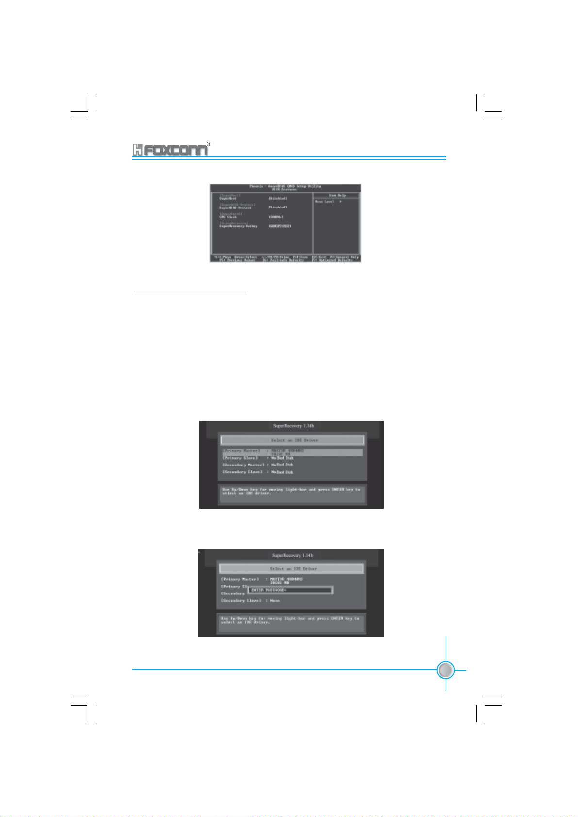
Chapter 6 Special BIOS Functions
Hard Disk Selection:
The hard disk selection menu will be displayed after you press the hotkey,
listing all the IDE HDDs installed in your system. You can switch the highlight
bar to make a selection and press “Enter” to confirm it.
Attention:
1) Make sure that you have selected a HDD before entering the main menu.
2) Make sure that the HDD you selected is ATA5 or higher. For the HDDs
lower than ATA5, there will be a message of “No Support” in the HDD list
menu listing beside the name of it.
3) Only one HDD can be opreated at a time.
Note: If you have assigned a password to the selected HDD, you will be
prompted to provide it before proceeding.
755/760A01 Series User Manual
755A01-032604.p65 2004-3-26, 15:2889
89
Page 98

Chapter 6 Special BIOS Functions
Main Menu:
Select a HDD to enter main menu. There are five function items, “DIVIDE HIDDEN PARTITION”, “RELEASE HIDDEN PARTITION”, “BACKUP”, “RECOVERY”
and “CHANGE PASSWORD”. You can switch the highlight bar to make a selection on the operation which should be performed on the HDD and confirm your
selection by pressing “Enter”. The following operation will be performed on the
disk you selected.
On-line help message
Divide Hidden Partition:
1. What’s a Hidden Partition:
SuperRecovery can be used to divide a hidden partition, which is to be reserved
for backing up HDD data. The operation of Division will erase all the old data
saved in the HDD, to make sure that the following operations can be continued.
Once the division is done, any future variation to the HDD will never affect the
area of hidden partition, such as virus, windows system breaking down and
data loss. SuperRecovery can recover all the data backed up in hidden partition.
The user can therefore easily get the computer on track again.
2. Divide Hidden Partition:
1) Enter a percentage of the HDD total capacity or an actual size in MB as
the size of the hidden partition, such as “30%” or “3000”. Press “Enter” to
confirm your input. As the average rate of compression is 50% or so, you
are suggested to divide 30% of the total as the capacity of the hidden
partition;
2) The system will then prompt you to Enter “Y” or “N” for confirmation.
Press “Y” to restart the computer, and the division for hidden partition
will be taken into effect after the system is restarted.
90
755A01-032604.p65 2004-3-26, 15:2890
755/760A01 Series User Manual
Page 99
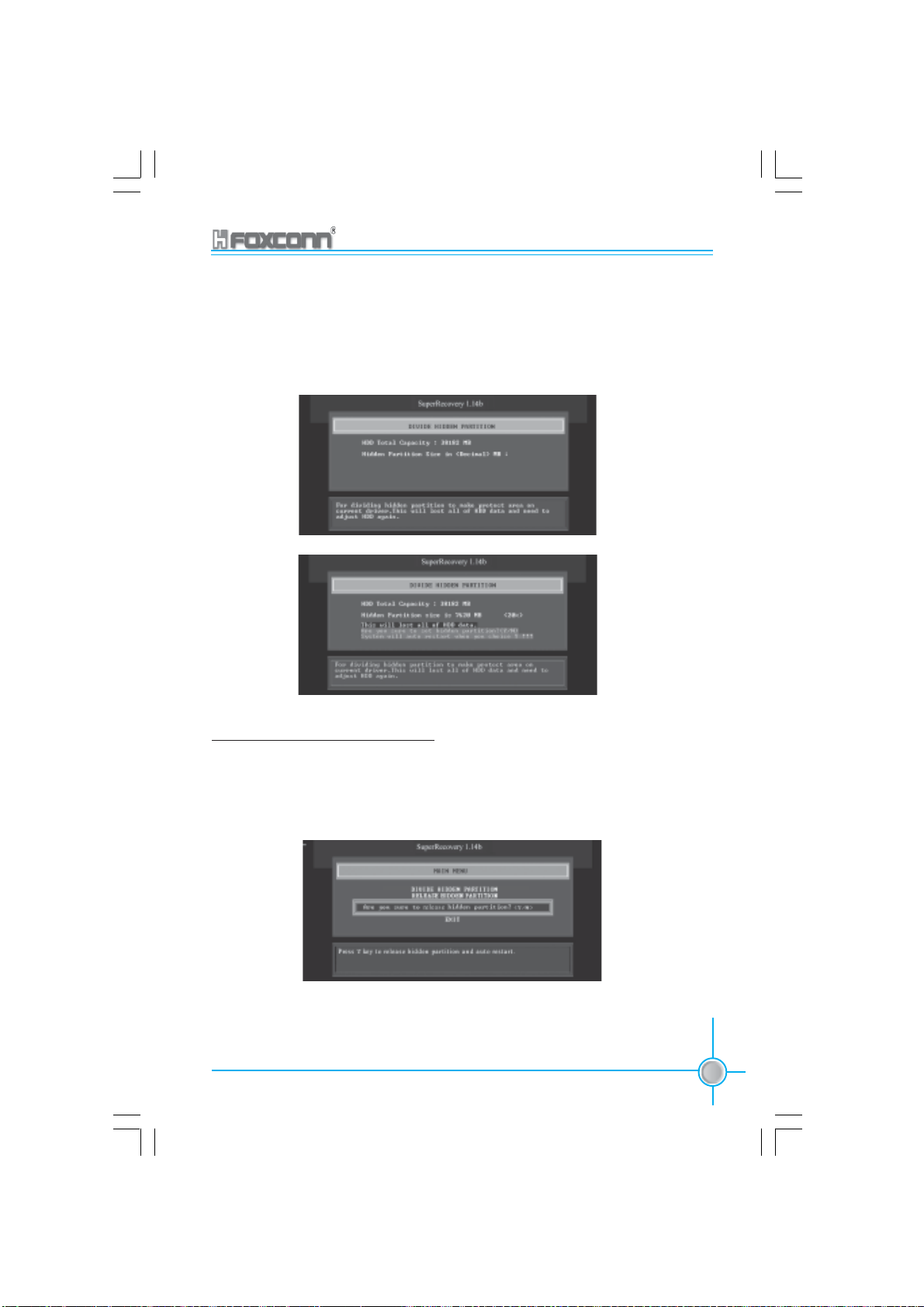
Chapter 6 Special BIOS Functions
Attention :
1) All the data will be cleared after division is in process. So you’d better do
the division against an empty HDD.
2) At the same time, the HDD capacity will decrease to make space for the
hidden partition, which is unavailable for your normal use.
Release Hidden Partition:
This is used to release the hidden partition. If you choose this item and press
“Y” to confirm, the system will be restarted to release the hidden partition. But
the released partition is still unavailable for you after the system is restarted. It’s
necessary for you to enable it by using FDISK, PQMAGIC, or some other tools.
755/760A01 Series User Manual
755A01-032604.p65 2004-3-26, 15:2891
91
Page 100

Chapter 6 Special BIOS Functions
Backup:
Select BACKUP to enter the Backup interface, where you can find the following
three sub-function items: “BACKUP CMOS SETUP”, “BACKUP PARTITION TABLE”
and “BACKUP HARDDISK DATA”. Switch the highlight bar by pressing the arrow
keys to make a selection and then press “Enter” to confirm your choice.
1. Backup CMOS Setup:
1) Supports backing up of the CMOS data.
2) The backing up or recovery of CMOS data should be operated on a
motherboard of the same model.
2. Backup Partition Table:
This function can help to backup all partition tables including extended
partitions.
92
755A01-032604.p65 2004-3-26, 15:2892
755/760A01 Series User Manual
 Loading...