

Page 1

RAID User Guide
Trademarks
All brand or product names mentioned are trademarks or registered trademarks of their respective holders.
Page 2

Intel ICH7R SATA RAID...................................................................... 1
1. Introduction .............................................................................................1
2. Installing SATA Hard Disks .....................................................................3
3. BIOS Configuration ................................................................................3
4. RAID Configuration Utility .......................................................................3
5. Installing Windows 2000/XP with RAID................................................14
6. Installing RAID Driver ...........................................................................16
Silicon 3114 SATA RAID(optional) ................................................... 17
1. Introduction ...........................................................................................17
2. SATARAID5 Features ............................................................................17
3. Installing Serial ATA (SATA) hard disks .................................................18
4. Setting the BIOS RAID items(optional) ................................................18
5. Creating and Deleting RAID Sets.........................................................19
6. Installing Drivers and Software ............................................................28
7. Creating / Naming Partitions................................................................30
8. Using Silicon Image SATA RAID GUI ....................................................33
ITE® 8212F RAID(optional) ............................................................... 38
1. Introduction ...........................................................................................38
2. Setting the BIOS RAID items ................................................................38
3. Entering the ITE® 8212(F) Setup Utility .................................................38
4. Auto-configuring a RAID array ..............................................................39
5. Defining a RAID array ...........................................................................40
6. Deleting a RAID array ...........................................................................41
7. Rebuilding a RAID array .......................................................................42
8. Viewing your RAID configuration ..........................................................43
9. Installing Windows 2000/XP with RAID................................................44
10. Installing RAID Driver .........................................................................45
11. Creating a RAID driver disk ................................................................45
Contents
Page 3

RAID User’s Guide
1
Intel ICH7R SATA RAID
1. Introduction
RAID (Redundant Array of Independent Disks) is a method of combining two hard
disk drives into one logical unit. The advantage of an Array is to provide better
performance or data fault tolerance. Fault tolerance is achieved through data redundant operation, where if one drives fails, a mirrored copy of the data can be
found on another drive. This can prevent data loss if the operating system fails or
hangs. The individual disk drives in an array are called members. The configuration information of each member is recorded in the reserved sector. That identifies
the drive as a member. All disk members in a formed disk array are recognized as
a single physical drive to the operating system.
Hard disk drives can be combined together through a few different methods. The
different methods are referred to as different RAID levels. Different RAID levels
represent different performance levels, security levels and implementation costs.
RAID 0 (Striping)
RAID 0 reads and writes sectors of data interleaved between multiple drives. If any
disk member fails, it affects the entire array. The disk array data capacity is equal
to the number of drive members times the capacity of the smallest member. The
striping block size can be set from 4KB to 128KB. RAID 0 does not support fault
tolerance.
RAID 1 (Mirroring)
RAID 1 writes duplicate data onto a pair of drives and reads both sets of data in
parallel. If one of the mirrored drives suffers a mechanical failure or does not
respond, the remaining drive will continue to function. Due to redundancy, the drive
capacity of the array is the capacity of the smallest drive. Under a RAID 1 setup, an
extra drive called the ¡°spare drive¡± can be attached. Such a drive will be activated to
replace a failed drive that is part of a mirrored array. Due to the fault tolerance, if any
RAID 1 drive fails, data access will not be affected as long as there are other
working drives in the array.
Page 4

RAID User’s Guide
2
RAID 5
RAID 5 Provides data striping at the byte level and also stripe error correction
information. This results in excellent performance and good fault tolerance. Level
5 is one of the most popular implementations of RAID.
RAID 10(0+1)
RAID 10 is a combination of striping and mirroring. This configuration provides
optimal speed and reliability, but you need four SATA hard disks.
Matrix RAID
Matrix RAID is a combination of RAID 0 and RAID 1 bringing you the best of both
worlds. You only need two SATA hard disks to utilize this function.
Advantages:
1. Faster data transfer.
2. Improve the safety and stability of data.
3. Swift and easy management for volume of data.
Page 5
RAID User’s Guide
3
2. Installing SATA Hard Disks
STEP 1: Install two SATA hard disks into the drive bays at least. (SATA_1, SATA_2,
SATA_3, SATA_4)
STEP 2: Connect one end of the SATA data cable to the motherboard’s one of
SATA connectors.
STEP 3: Connect the other end of the SATA data cable to one SATA hard disk.
STEP 4: Connect one end of the second SATA data cable to the motherboard’s
the other of SATA connectors.
STEP 5: Connect the other end of SATA data cable to the other SATA hard disk.
3. BIOS Configuration
1. Enter the BIOS setup program by pressing the <Del> key during the POST
(Power-On Self Test ).
2. Select the OnChip IDE Device item form Integrated Peripherals menu.
3. Switch the SATA Mode option to [RAID].
4. Save the BIOS setting and exit the BIOS setup program.
4. RAID Configuration Utility
A. Setting RAID 0
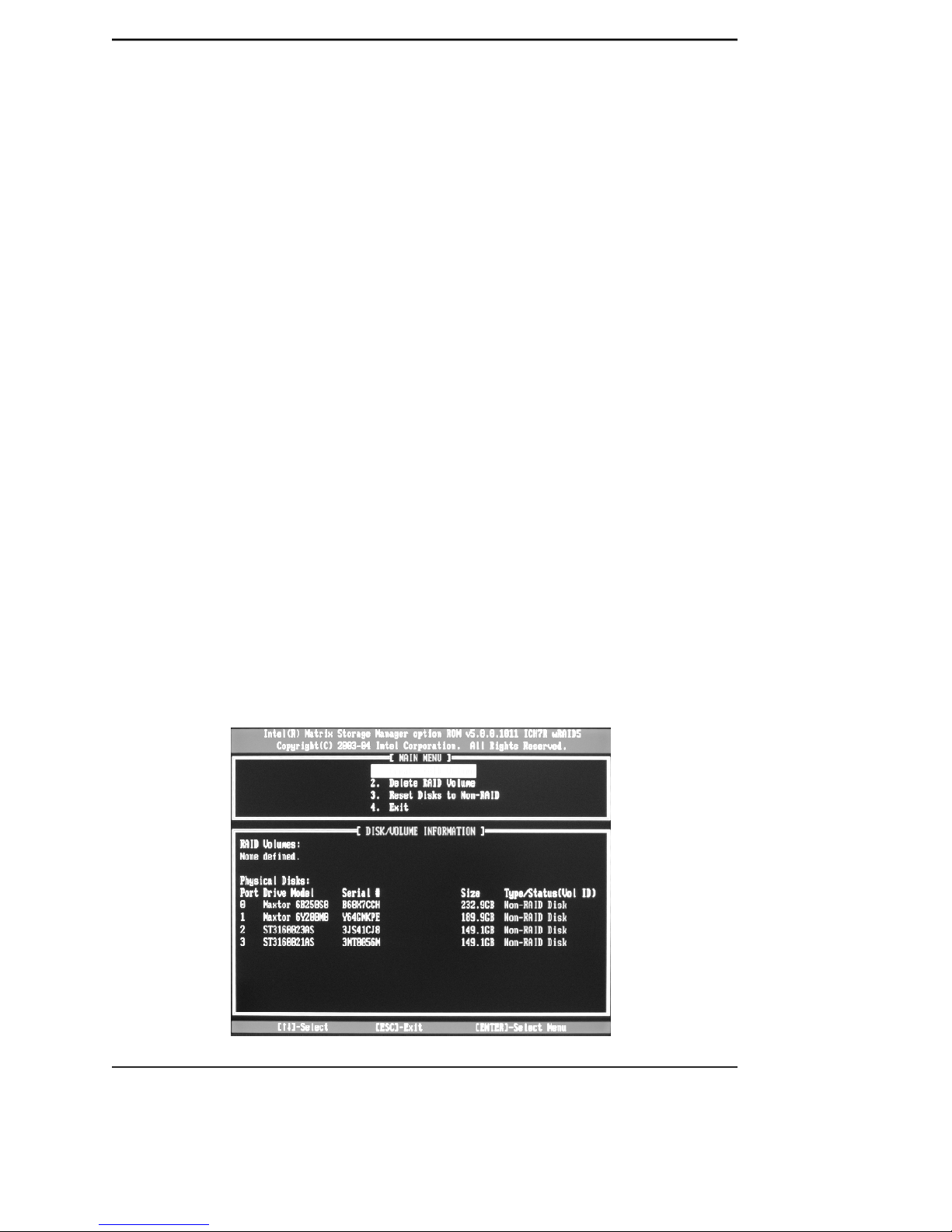
a. When the system powers on, the following information will appear on screen:
Press the <Ctrl-I> to enter Configuration Utility.
At this moment, press <Ctrl>+<I> to enter Main Menu:
Page 6
RAID User’s Guide
4
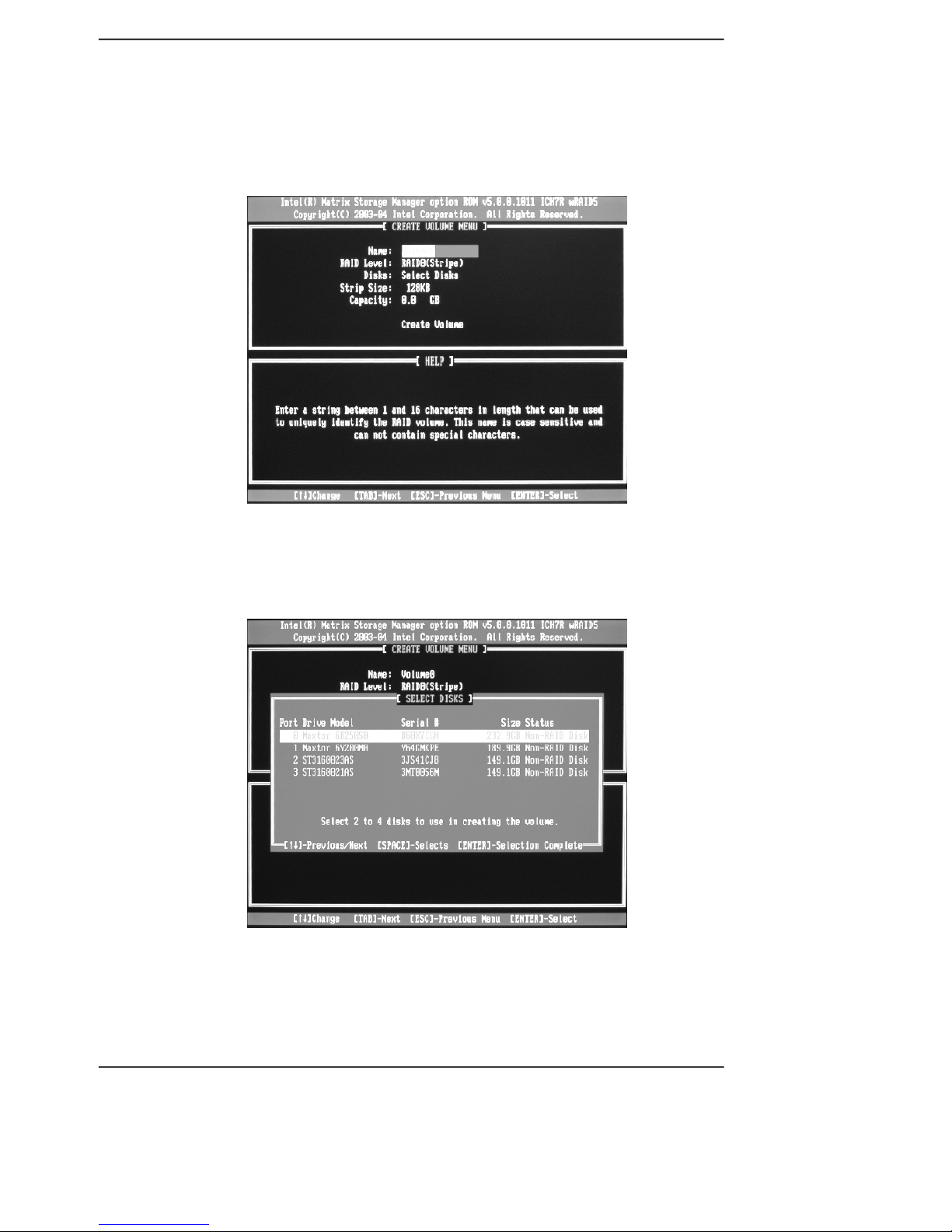
b. Choose Create RAID Volume and press <Enter> to enter. Press <Tab> to
switch to RAID Level item, and then use Up and Down arrow keys to select
RAID0 (Stripe), pressing <Enter> confirms.
c. Using up or down arrow key to select the hard disks you want to set RAID 0 from
Disks item, <Space> key to confirm and <Enter> key to finish the selection.
Page 7
RAID User’s Guide
5
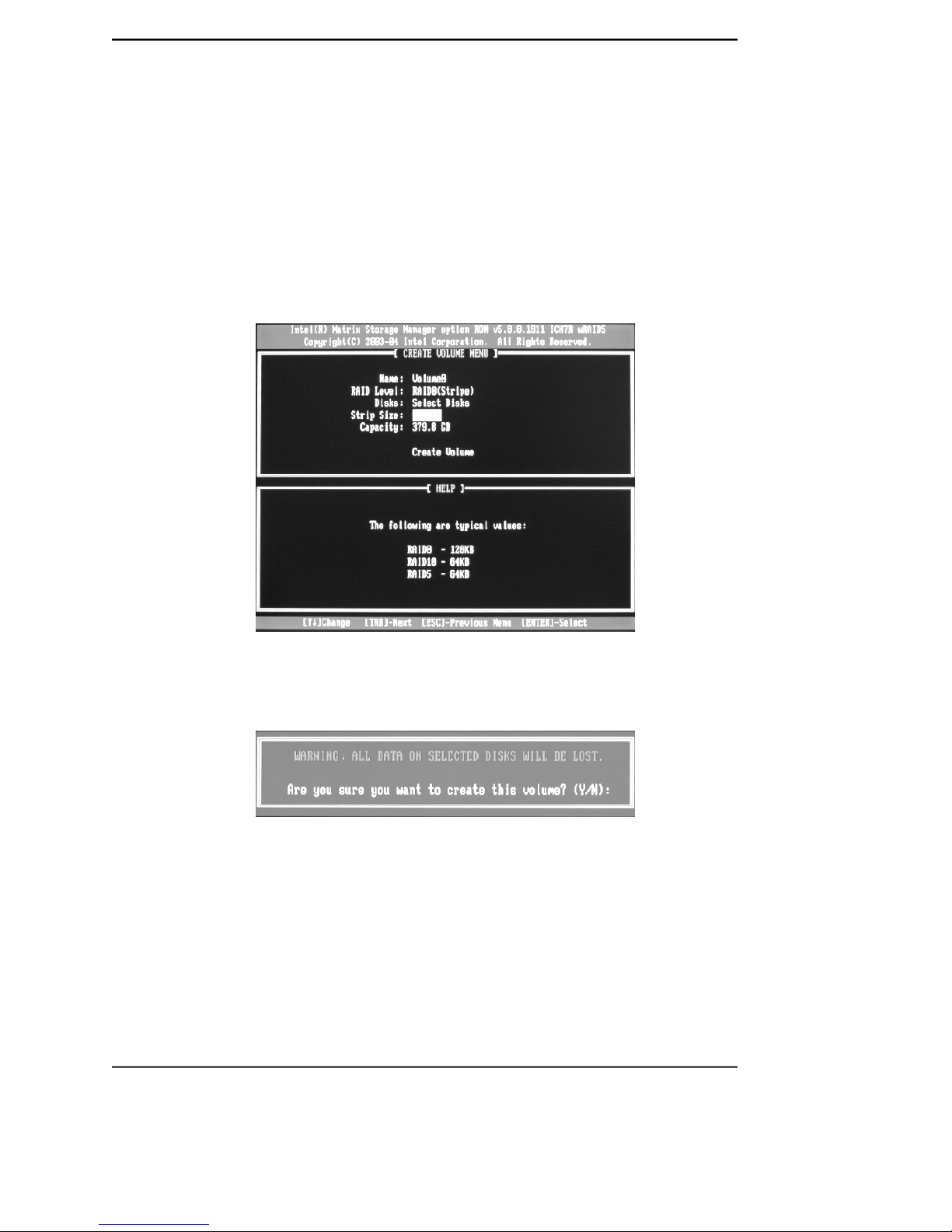
d. Use Up and Down arrow keys to select desired strip size when enter Strip Size
menu. The available values range from 4KB to 128KB. The strip value should
be based on the planned drive usage. Some suggested selections are listed
below. The default selection is 128KB.
16K_Best for sequential transfer
64K_Good general purpose strip size
128K_Best performance for most desktops and workstations
e. Press the <Enter> key after the Create Volume prompt appears to create the
array. Press the <Y> key after the prompt to confirm this selection.
f. Select option 4. Exit in main menu and press the <Enter> key to exit the RAID
configuration utility. Press <Y> key to confirm the exit.
Page 8

RAID User’s Guide
6
B. Setting RAID1
a. Select RAID1 (Mirror) by using Up and Down arrow keys in RAID Level item.
Press the <Enter> key to make selecting.
b. Using up or down arrow key to select the hard disks you want to set RAID 1 from
Disks item, <Space> key to confirm and <Enter> key to finish the selection.
c. Press the <Enter> key after the Create Volume prompt appears to create the
array. Press the <Y> key after the prompt to confirm this selection.
Page 9

RAID User’s Guide
7
C. Setting RAID5
a. Select RAID5 (Parity) by using Up and Down arrow keys in RAID Level item.
Press the <Enter> key to make selecting.
b. Using up or down arrow key to select the hard disks you want to set RAID 5 from
Disks item, <Space> key to confirm and <Enter> key to finish the selection.
d. Select option 4. Exit in main menu and press the <Enter> key to exit the RAID
configuration utility. Press <Y> key to confirm the exit.
Page 10

RAID User’s Guide
8
c. Use Up and Down arrow keys to select desired strip size when enter Strip Size
menu. The available values range from 4KB to 128KB. The strip value should
be based on the planned drive usage. Some suggested selections are listed
below. The default selection is 128KB.
16K_Best for sequential transfer
64K_Good general purpose strip size
128K_Best performance for most desktops and workstations
d. Press the <Enter> key after the Create Volume prompt appears to create the
array. Press the <Y> key after the prompt to confirm this selection.
e. Select option 4. Exit in main menu and press the <Enter> key to exit the RAID
configuration utility. Press <Y> key to confirm the exit.
Page 11

RAID User’s Guide
9
D. Setting RAID 10(RAID0+1)
a. To utilize RAID 10 function, four SATA hard disks should be installed.
b. Choose Create RAID Volume and press <Enter> to enter. Press <Tab> to
switch to RAID Level item, and then use Up and Down arrow keys to select
RAID10(RAID0+1), pressing <Enter> confirms.
c. Use Up and Down arrow keys to select desired strip size when enter Strip
Size menu. The available values range from 4KB to 128KB. The strip value
should be based on the planned drive usage. Some suggested selections
are listed below. The default selection is 128KB.
16K_Best for sequential transfer
64K_Good general purpose strip size
128K_Best performance for most desktops and workstations
Page 12

RAID User’s Guide
10
d. Press the <Enter> key after the Create Volume prompt appears to create the
array. Press the <Y> key after the prompt to confirm this selection.
e. Select option 4. Exit in main menu and press the <Enter> key to exit the RAID
configuration utility. Press <Y> key to confirm the exit.
f. You may see the RAID type in the main menu, when you finished the setting
steps.
Note:
This operation will delete all the data from hard disk, so please take
care. And our company will not be responsible for data lose and benefit
damage caused.
Page 13

RAID User’s Guide
11
E. Setting Matrix RAID
a. Intel ICH7R chipset features a new RAID form named Matrix RAID, a combina-
tion of RAID 0 and RAID 1 bringing you the best of both worlds.
b. Follow Setting RAID 0 steps to set RAID 0. You should divide half capacity size
or less for RAID 1 in Capacity item. (For example, if the SATA hard disks total
capacity is 300 GB, divide 150 GB or less capacity for RAID 1.)
c. Follow Setting RAID 1 steps to set RAID 1.
Page 14
RAID User’s Guide
12
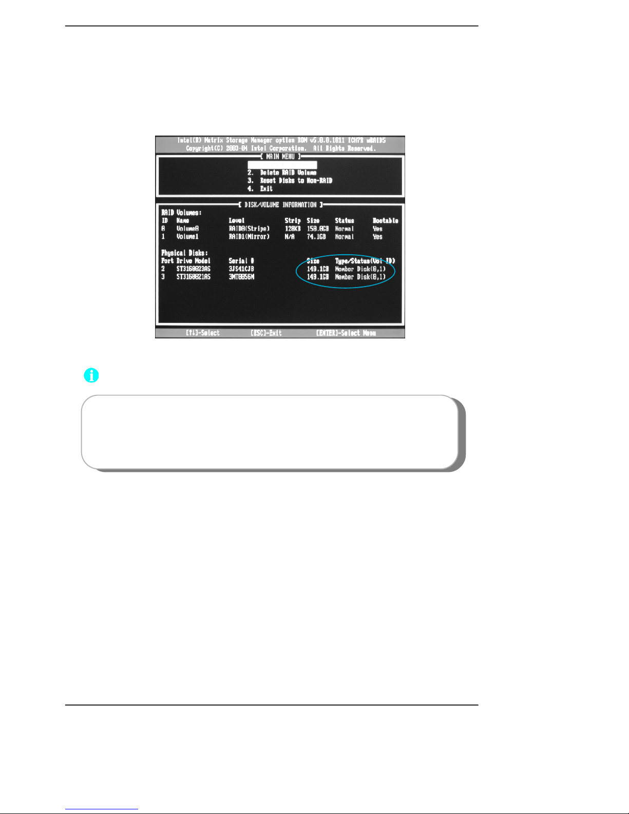
c. You may see the RAID type (Member Disk (0,1)) in the main menu, when you
finished the setting steps.
Note:
This operation will delete all the data from hard disk, so please take
care. And our company will not be responsible for data lose and benefit
damage caused.
Page 15
RAID User’s Guide
13
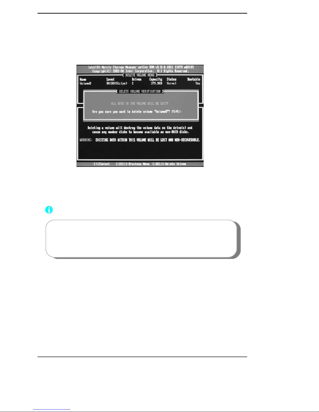
F. Delete RAID Volume
1. Select Delete RAID Volume in main menu and press <Enter> key.
2. Press <Del> key to delete the RAID volume in below screen.
3. Press <Y> key to confirm the volume deletion, and press <N> to cancel the
operation.
Note:
This operation will delete all the data from hard disk, so please take
care. And our company will not be responsible for data lose and benefit
damage caused.
Page 16

RAID User’s Guide
14
G. Reset RAID
1. Select Reset Disk to Non-RAID in main menu and press <Enter> key to delete
the RAID setting and remove all RAID structures from the drives. Then you will
see:
2. Press <Y> key to confirm the volume deletion, press <N> to cancel the operation.
5. Installing Windows 2000/XP with RAID
1. Setup the desired RAID mode in BIOS setup follow the above steps.
2. Insert Operation System installation disk into CD-ROM and start up the setup
program.
3. Press <F6> when the following picture appears on screen:
4. Press <S> key to specify additional equipment when below picture appears.
Are you sure you want to reset RAID data on selected? (Y/N):
Page 17

RAID User’s Guide
15
5.Insert the add-on RAID installation disk into floppy disk drive (ICH7R S-ATA
RAID Driver floppy) following the on-screen instructions and press <Enter> to
continue.
6.Select the right choice and press <Enter> to continue. The choice is deter
mined by South Bridge.
Page 18

RAID User’s Guide
16
7. Press <Enter> to continue.
8. After this, the installation steps are the same as normal setup methods. No
details are provided herein.
6. Installing RAID Driver
When you finish installing Operation System with RAID, in order to enable RAID
function you need to install RAID driver. Please refer to Chapter 4 of motherboard
user manual for installation steps.
 Loading...