

Page 1

Inferno Katana Series
Motherboard
User’s Manual
Page 2

Statement:
This manual is the intellectual property of Foxconn, Inc. Although the information
in this manual may be changed or modied at any time, Foxconn does not obligate
itself to inform the user of these changes.
Trademark:
All trademarks are the property of their respective owners.
Version:
User’s Manual V1.0 for Inferno Katana Series motherboard.
P/N: 3A221SM00-000-G
Symbol description:
Caution: refers to important information that can help you to use motherboard
better, and tells you how to avoid problems.
Warning: indicating a potential risk of hardware damage or physical injury may
exist.
WEEE:
The use of this symbol indicates that this product may not be treated as household
waste. By ensuring this product is disposed of correctly, you will help prevent potential
negative consequences for the environment and human health, which could other-
wise be caused by inappropriate waste handling of this product. For more detailed
information about recycling of this product, please contact your local city ofce, your
household waste disposal service or the shop where you purchased this product.
More information:
If you want more information about our products, please visit Foxconn’s
website: http://www.foxconnchannel.com
C
A
U
T
I
O
N
!
W
A
R
N
I
N
G
!
© All rights reserved.
All trade names are registered trademarks of respective manufacturers listed.
All images are for reference only, please refer to the physical motherboard for specic features.
Page 3

Declaration of conformity
HON HAI PRECISION INDUSTRY COMPANY LTD
66 , CHUNG SHAN RD., TU-CHENG INDUSTRIAL DISTRICT,
TAIPEI HSIEN, TAIWAN, R.O.C.
declares that the product
Motherboard Inferno Katana/Inferno Katana GTI
is in conformity with
(reference to the specication under which conformity is declared in
accordance with 89/336 EEC-EMC Directive)
■ EN 55022: 1998/A2: 2003 Limits and methods of measurements of radio
disturbance characteristics of information technology
equipment
■ EN 61000-3-2/:2000 Electromagnetic compatibility (EMC)
Part 3: Limits
Section 2: Limits for harmonic current emissions
(equipment input current <= 16A per phase)
■ EN 61000-3-3/A1:2001 Electromagnetic compatibility (EMC)
Part 3: Limits
Section 2: Limits of voltage uctuations and icker in low
voltage supply systems for equipment with rated current
<= 16A
■ EN 55024/A2:2003 Information technology equipment-Immunity
characteristics limits and methods of measurement
Signature : Place / Date : TAIPEI/2009
Printed Name : James Liang
Page 4

Declaration of conformity
Trade Name: FOXCONN
Model Name: Inferno Katana/Inferno Katana GTI
Responsible Party: PCE Industry Inc.
Address: 458 E. Lambert Rd.
Fullerton, CA 92835
Telephone: 714-738-8868
Facsimile: 714-738-8838
Equipment Classication: FCC Class B Subassembly
Type of Product: Motherboard
Manufacturer: HON HAI PRECISION INDUSTRY
COMPANY LTD
Address: 66 , CHUNG SHAN RD., TU-CHENG
INDUSTRIAL DISTRICT, TAIPEI HSIEN,
TAIWAN, R.O.C.
Supplementary Information:
This device complies with Part 15 of the FCC Rules. Operation is subject to the following
two conditions : (1) this device may not cause harmful interference, and (2) this device
must accept any interference received, including interference that may cause undesired
operation.
Tested to comply with FCC standards.
Signature : Date : 2009
Page 5

Installation Precautions
Please carefully read the following procedures to install your computer :
■ It is suggested to select high-quality, certied fans in order to avoid damage
to the motherboard and CPU due to high temperature. Never turn on the
computer if the CPU fan is not properly installed.
■ We cannot guarantee that your system can operate normally when your
CPU is overclocked. Normal operation depends on the overclocking capac-
ity of your device.
■ If there is any, when connecting USB, audio, 1394a, RS232 COM, IrDA or
S/PDIF cables to the internal connectors on the motherboard, make sure
their pinouts are matching with the connectors on the motherboard. Incorrect
connections might damage the motherboard.
■ When handling the motherboard, avoid touching any metal leads or connec-
tors.
■ If there is a PCI Express x16 graphics card installed in your system, we
recommend using a 24-pin ATX power supply to get the best performance.
■ Before turning on the power, please make sure the power supply AC input
voltage setting has been congured to the local standard.
■ To prevent damage to the motherboard, do not allow screws to come in contact
with the motherboard circuit or its components. Also, make sure there are no
leftover screws or metal components placed on the motherboard or within the
computer casing.
■ If you are uncertain about any installation steps or have a problem related to
the use of the product, please consult a certied computer technician.
C
A
U
T
I
O
N
!
■ Electrostatic discharge (ESD) is the sudden and momentary electric current
that ows between two objects at different electrical potentials. Normally it
comes out as a spark which will quickly damage your electronic equipment.
Please wear an electrostatic discharge (ESD) wrist strap when handling
components such as a motherboard, CPU or memory.
■ Ensure that the DC power supply is turned off before installing or removing
CPU, memory, expansion cards or other peripherals. It is recommended to
unplug the AC power cord from the power supply outlet. Failure to unplug
the power supply cord may result in serious damage to your system.
W
A
R
N
I
N
G
!
Page 6

TABLE OF CONTENTS
Chapter 1 Product Introduction
Product Specications ..............................................................................2
Layout.......................................................................................................4
Back Panel Connectors ............................................................................5
Chapter 2 Hardware Install
Install the CPU and CPU Cooler ..............................................................8
Install the Memory ..................................................................................11
Install an Expansion Card ......................................................................13
Install other Internal Connectors ............................................................14
Jumpers ..................................................................................................18
OnBoard Button......................................................................................19
OnBoard Debug LED .............................................................................19
OnBoard LED .........................................................................................20
BIOS Debug Code Description...............................................................20
Chapter 3 BIOS Setup
Enter BIOS Setup ...................................................................................27
Main Menu..............................................................................................27
System Information ................................................................................29
Advanced BIOS Features.......................................................................31
Advanced Chipset Features ...................................................................35
Boot Conguration Features ..................................................................39
Power Management Setup .....................................................................41
PC Health Status ....................................................................................43
Quantum BIOS ......................................................................................44
BIOS Security Features..........................................................................51
Load Optimal Defaults ............................................................................52
Save & Exit Setup ..................................................................................52
Exit Without Saving ................................................................................52
Chapter 4 CD Instruction
Utility CD Introduction.............................................................................54
Aegis Panel
Main Page ........................................................................................57
HW Monitor ......................................................................................58
Overclocking .....................................................................................60
Conguration ....................................................................................60
FOX LiveUpdate
Local Update ....................................................................................61
Page 7

Online Update ..................................................................................63
Congure .........................................................................................66
About & Help ....................................................................................68
FOX LOGO .............................................................................................69
FOX DMI ................................................................................................70
Chapter 5 RAID Conguration
RAID Conguration Introduction
.............................................................73
Intel® Matrix Storage Manager ..............................................................75
Create a RAID Driver Diskette ...............................................................76
BIOS Conguration ................................................................................78
Create RAID in BIOS
..............................................................................78
Install a New Windows XP ...................................................................105
Existing Windows XP with RAID built as data storage .........................109
Appendix - CrossFireXTM Technology .......................................................... 113
Appendix - NVIDIA® SLI™ Technology ........................................................115
Technical Support :
Website :
http://www.foxconnchannel.com
Support Website :
http://www.foxconnsupport.com
Worldwide online contact Support :
http://www.foxconnsupport.com/inquiry.aspx
CPU Support List :
http://www.foxconnsupport.com/cpusupportlist.aspx
Memory, VGA Compatibility List :
http://www.foxconnsupport.com/complist.aspx
Support
Page 8

Thank you for buying Foxconn Inferno Katana Series motherboard.
Foxconn products are engineered to maximize computing power,
providing only what you need for break-through performance.
With advanced overclocking capability and a range of connectivity
features for today multi-media computing requirements, Inferno
Katana/Inferno Katana GTI enables you to unleash more power
from your computer.
This chapter includes the following information:
■ Product Specications
■ Layout
■ Back Panel Connectors
Page 9

1
2
1-1 Product Specications
CPU Support LGA 1156 socket Intel® CPU: Intel® Core™ i7/ i5 processors
Chipset Intel® P55 chipset
Memory 4 x 240-pin DDR3 DIMM sockets
Support up to 16GB of system memory
Support
three channel DDR3 1800(oc*)/1600(oc*)/1333/1066MHz architecture
( oc*: Overclocking)
Audio Realtek 8-channel audio chip
High Denition Audio
2/4/5.1/7.1-channel
Support for S/PDIF out
Support Jack-Sensing function
Support DTSTM connect and Dolby Digital Live technology (Only for Inferno Katana)
LAN Realtek 10/100/1000Mb/s LAN chip
Expansion Slots 3 x PCI Express x16 slots
2 x PCI Express x1 slots
1 x PCI slot
Onboard Serial ATA 6 x SATA connectors (Controlled by Intel® P55)
300MB/s data transfer rate
Support hot plug and NCQ (Native Command Queuing)
USB Support hot plug
Supports up to 14 x USB 2.0 ports (8 rear panel ports, 3 onboard USB head-
ers supporting 6 extra ports)
Support USB 2.0 protocol up to 480Mb/s
Internal Connectors 1 x 24-pin ATX main power connector
1 x 8-pin ATX 12V power connector
1 x CPU fan header (4-pin)
5 x System fan headers (3-pin)
1 x CD-IN connector
1 x Front Audio connector
2 x SPDIF-OUT connectors
3 x USB 2.0 connectors (supporting 6 x USB devices)
1 x Front Panel connector
6 x SATA connectors (Controlled by Intel® P55)
1 x IDE connector (Controlled by Marvell Chipset)
1 x 1394a connector (Only for Inferno Katana)
1 x Speaker connector
1 x Fuzzy Equalizer
Back Panel 1 x PS/2 keyboard port
Connectors 1 x Clear CMOS button
2 x eSATA ports (Controlled by Marvell Chipset, Only for Inferno Katana)
1 x 1394a port (Only for Inferno Katana)
1 x RJ-45 LAN port
1 x Optical S/PDIF out port
Page 10

1
3
1 x Coaxial S/PDIF out port
8 x USB 2.0 ports
8-channel Audio Ports
Hardware Monitor System voltage detection
CPU/System temperature detection
CPU/System fan speed detection
CPU/System overheating shutdown
CPU/System fan speed control
PCI Express x1 Support 250MB/s (500MB/s concurrent) bandwidth
Low power consumption and power management features
PCI Express x16 Gen1.0 Support 4GB/s (8GB/s concurrent) bandwidth
Low power consumption and power management features
PCI Express x16 Gen2.0 Support 8GB/s (16GB/s concurrent) bandwidth
Low power consumption and power management features
Green Function Support ACPI (Advanced Conguration and Power Interface)
Support S0 (normal), S1 (power on suspend), S3 (suspend to RAM), S4
(suspend to disk), and S5 (soft - off)
Bundled Software Aegis Panel
FOX LiveUpdate
FOX LOGO
FOX DMI
Operating System Support for Microsoft® Windows® XP/Vista
Form Factor ATX Form Factor, 12 inches x 9.6 inches (30.5cm x 24.4cm)
Page 11

1
4
1-2 Layout
Note : The above motherboard layout is for reference only, please refer to the physical
motherboard for detail.
1. 8-pin ATX 12V Power Connector
2. S/PDIF Out 2 Connector
3. FAN4 Header
4. FAN5 Header
5. PCI Express x1 Slots
6. PCI Express x16 Slots
7. PCI Slot
8. CD_IN Connector
9. Front Audio Connector
10. S/PDIF Out 3 Connector
11. FAN1 Header
12. Clear CMOS Jumper
13.
1394a connector (Only for Inferno Katana)
14. Front USB Connectors
15. Front Panel Connector
16. Reset Button
17. Power On Button
18. SATA Connectors
19. Intel® P55 Chipset
20. IDE Connector
21. Speaker Connector
22. FAN3 Header
23. FAN2 Header
24.
Force_Reset Button (Only for Inferno Katana)
25. Fuzzy Equalizer
26. 24-pin ATX Power Connector
27. DDR3 DIMM Slots
28. CPU_FAN1 Header
29. LGA 1156 CPU Socket
1
20
9
24
29
5
15
28
27
18
21
23456 67
8
10
13
14
16
17
19 22 23
25 26
11
12
Page 12
1
5
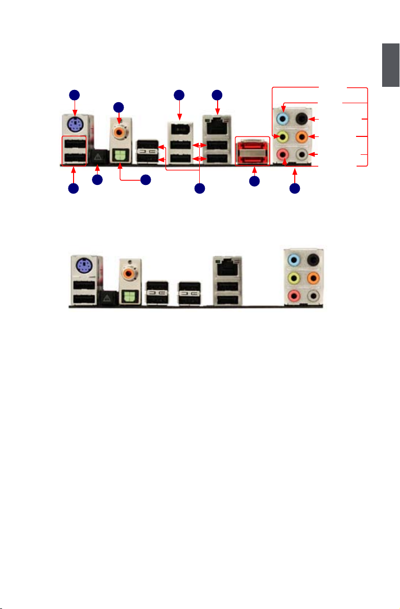
1-3 Back Panel Connectors
1. PS/2 Keyboard Port
Use the upper port (purple) to connect a PS/2 keyboard.
2. USB Ports
The USB port supports the USB 2.0/1.1 specication. Use this port for USB devices such as an
USB keyboard/mouse, USB printer, USB ash drive and etc.
3. Clear CMOS Button
Turn off the AC power supply, push the CLS_CMOS button and hold there for a couple of
seconds to clear CMOS.
4. Coaxial S/PDIF Out Port
This port provides digital audio out to an external audio system that supports digital coaxial
audio. Before using this feature, ensure that your audio system provides a coaxial digital audio
in connector.
5. Optical S/PDIF Out Port
This port provides digital audio out to an external audio system that supports digital optical
audio.
6. 1394a Port (Only for Inferno Katana)
This port is used to connect a 1394a device.
7. External SATA Ports (Only for Inferno Katana)
To connect external SATA device(s) to your system by expanding the internal SATA port(s) to
the chassis back panel. External SATA device shall provide power by its own.
Inferno Katana:
LAN PortPS/2 Keyboard Port
8
USB Ports
1
6
1394a Port
External
SATA Ports
4
7
Optical S/PDIF
Out Port
5
2
USB Ports
Coaxial S/PDIF
Out Port
9
Audio Ports
2
3
Clear CMOS
Button
Line Out
Microphone
Subwoofer
Rear Speaker
Side Speaker
Line In
Inferno Katana GTI:
Page 13
1
6
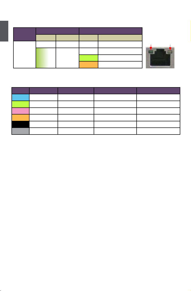
8. RJ-45 LAN Port
The Ethernet LAN port provides Internet connection at up to 10/100/1000Mb/s data rate.
9. Audio Ports
For the denition of each audio port, please refer to the table below :
Port 2-channel 4-channel 5.1-channel 7.1-channel
Blue Line In Line In Line In Line In
Green Line Out Front Speaker Out Front Speaker Out Front Speaker Out
Pink Microphone In Microphone In Microphone In Microphone In
Orange - - Center/Subwoofer Out Center/Subwoofer Out
Black - Rear Speaker Out Rear Speaker Out Rear Speaker Out
Grey - - - Side Speaker Out
LAN Type
Left: Active Right: Link
Status Description Status Description
1000M
Off No Link Off No Link
Green
Blinking
Data
Activity
Off 10Mb/s Connection
Green 100Mb/s Connection
Orange 1000Mb/s Connection
Active
LED
Link
LED
Page 14

This chapter introduces the hardware installation process, including
the installation of the CPU, memory, power supply, slots, pin
headers and the mounting of jumpers. Caution should be exercised
during the installation of these modules. Please refer to the
motherboard layout prior to any installation and read the contents in
this chapter carefully.
This chapter includes the following information :
■ Install the CPU and CPU Cooler
■ Install the Memory
■ Install an Expansion Card
■ Install other Internal Connectors
■ Onboard Button
■ Onboard Debug LED
■ Onboard LED
■ BIOS Debug Code Description
Please visit the following website for more supporting information about your motherboard.
CPU Support List:
http://www.foxconnsupport.com/cpusupportlist.aspx
Memory, VGA Compatibility List:
http://www.foxconnsupport.com/complist.aspx
Page 15
8
2
8
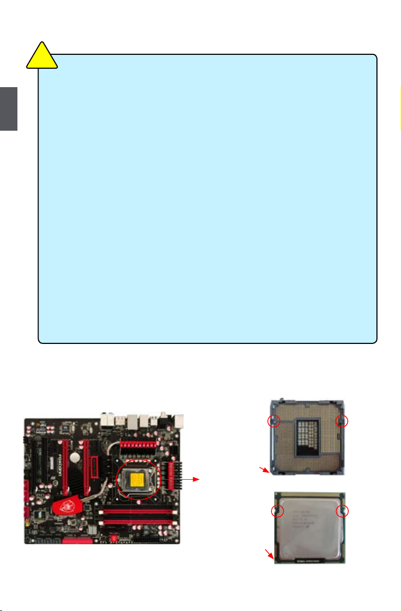
2-1 Install the CPU and CPU Cooler
Install the CPU
Locate the alignment keys on the motherboard CPU socket and the notches on the CPU.
Read the following guidelines before you begin to install the CPU:
■ Make sure that the motherboard supports the CPU.
■ Always turn off the computer and unplug the power cord from the power supply before
installing the CPU to prevent hardware damage.
■ Locate the pin one of the CPU. The CPU cannot be inserted if oriented incorrectly. (Or
you may locate the notches on both sides of the CPU and alignment keys on the CPU
socket.)
■ Apply an even and thin layer of thermal grease on the surface of the CPU.
■ Do not turn on the computer if the CPU cooler is not installed, otherwise overheating
and damage of the CPU may occur.
■ Set the CPU host frequency in accordance with the CPU specications. It is not
recommended that the system bus frequency be set beyond hardware specications
since it does not meet the standard requirements for the peripherals. If you wish to
set the frequency beyond the standard specications, please do so according to your
hardware specications including the CPU, graphics card, memory, hard drive, etc.
Hyper-Threading Technology System Requirements:
(Go to Intel's website for more information about the Hyper-Threading Technology)
■ An Intel® CPU that supports HT Technology
■ A chipset that supports HT Technology
■ An operating system that is optimized for HT Technology
■ A BIOS that supports HT Technology and has it enabled
C
A
U
T
I
O
N
!
LGA1156 CPU Socket
Alignment Key
Pin-1 corner of the
CPU Socket
LGA1156 CPU
Notch
Pin-1 triangle
marking of CPU
Page 16

9
2
9
Follow the steps to install the CPU onto the CPU socket :
2. Lift the metal cover on the CPU
socket.
3. Remove protective socket cover.
5. When CPU is properly seated,
replace the metal cover and push the
CPU socket lever back to its locked
position.
4. Check pin one marking (triangle)
with the pin one corner of the CPU
socket, align the CPU notches with
the socket alignment keys and gently
put the CPU onto the socket.
Before installing the CPU, make sure to turn off the computer and unplug the power
cord from the power outlet to prevent damage to the CPU.
CA
UTI
O
N
!
1. Release the CPU socket lever.
Page 17

10
2
10
Install the CPU Cooler
Follow the steps below to correctly install the CPU cooler on the motherboard.
1. Apply and spread an even thermal
grease on the surface of CPU.
2. Place the four bolts of the CPU
cooler to the holes of the motherboard,
push them straight down from the top,
and the bolts will be fastened on the
motherboard. That's it.
3. Chec k the sol de r side of the
motherboard, the push pin should be
xed as depicted in the picture.
3
2
1
4. Attach t he 4-wire C PU cooler
connector to the CPU FAN header
on the motherboard .
Release bolts of CPU cooler from
motherboard :
1.Tu r n i n g the push p i n ( b o l t )
along with the direction of arrow
(counterclockwise).
2. Pull the push pin straight up.
3. Turning push pin clockwise to its
default position.
Use extreme care when removing the CPU cooler because the thermal grease may
adhere to the CPU. Inadequately removing the CPU cooler may damage the CPU.
C
A
U
T
I
O
N
!
Page 18

11
2
11
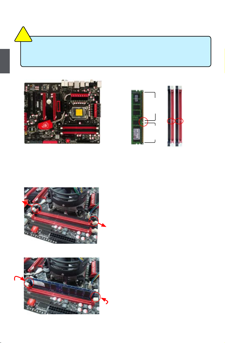
2-2 Install the Memory
Dual Channel Memory Conguration
This motherboard provides four DDR3 memory sockets and supports Dual Channel Technology.
When memory is installed, the BIOS will automatically check the memory in your system.
Four DDR3 memory sockets are divided into two channels and each channel has two memory
sockets as following:
Channel 0: DIMM1, DIMM2
Channel 1: DIMM3, DIMM4
The combinations of DIMM modules are:
Read the following guidelines before you begin to install the memory:
■ Make sure that the motherboard supports the memory. It is recommended that memory
of the same capacity, brand, speed, and chips be used.
■ Always turn off the computer and unplug the power cord from the power outlet before
installing the memory to prevent hardware damage.
■ Memory modules have a foolproof design. A memory module can be installed in only
one direction. If you are unable to insert the memory, switch the direction.
■ It is recommended that memory of the same capacity, brand, speed, and chips be
used and please select dual channel rst to achieve optimum performance.
C
A
U
T
I
O
N
!
DIMM1 DIMM2 DIMM3 DIMM4
Single Channel DS/SS - - -
Single Channel DS/SS DS/SS -
Single Channel - - DS/SS -
Single Channel - - DS/SS DS/SS
Dual Channel DS/SS - DS/SS -
Dual Channel - DS/SS - DS/SS
Dual Channel DS/SS DS/SS DS/SS DS/SS
(DS : Double Side, SS : Single Side, - : No Memory)
■ For this motherboard, DIMM(1,2), DIMM(3,4), are two pairs of channels. In each pair of
DIMM channel, you need to install red DIMM rst, then install black DIMM the second.
Black DIMM can not function if no red DIMM is installed.
C
A
U
T
I
O
N
!
Page 19
12
2
12
Installing a Memory
If you take a look at front side of memory module, it has asymmetric pin counts on both sides separated
by a notch in the middle, so it can only t in one direction. Follow the steps below to correctly install
your memory modules into the sockets.
Step 1:
Spread the clips at both ends of the memory socket.
Place the memory module onto the socket, then put
your ngers on top edge of the module, and push
it down rmly and seat it vertically into the memory
socket.
Step 2:
The clips at both ends of the socket will snap into place
when the memory module is securely inserted.
96-Pin
144-Pin
Notch
■ Before installing a memory module, make sure to turn off the computer and unplug the
power cord from the power outlet to prevent damage to the memory module. Be sure to
install DDR3 DIMMs on this motherboard.
C
A
U
T
I
O
N
!
Page 20

13
2
13
2-3 Install an Expansion Card
Follow the steps below to correctly install your expansion card in the expansion slot.
1. Locate an expansion slot that supports your card. Remove the metal slot cover from the chassis
back panel.
2. Align the card with the slot, and press down on the card until it is fully seated in the slot.
3. Make sure the metal contacts on the card are completely inserted into the slot.
4. Secure the card's metal bracket to the chassis back panel with a screw.
5. After installing all expansion cards, replace the chassis cover.
6. Turn on your computer. If necessary, go to BIOS Setup to make any required BIOS changes for
your expansion card(s).
7. Install the driver provided with the expansion card in your operating system.
Installing and Removing a PCI Express x16 Graphics Card:
• Installing a Graphics Card:
Gently insert the graphics card into the PCI Express x16 slot.
Make sure the graphics card is locked by the latch at the end of
the PCI Express x16 slot.
• Removing the Card:
Push the latch at the end of the PCI Express x16 slot to release
the card and then pull the card straight up from the slot.
■ Make sure the motherboard supports the expansion card. Carefully read the manual
that came with your expansion card.
■ Always turn off the computer and unplug the power cord from the power outlet before
installing an expansion card to prevent hardware damage.
■ The two red PCI Express x16 slots can not reach 16X at the same time. Only plug one
graphic card into any of them, it can work at 16X. Plug two, they will work at 8X.
C
A
U
T
I
O
N
!
PCI
PCI Express x1
PCI Express x16
PCI Express x4
Page 21
14
2
14
2-4 Install other Internal Connectors
Power Connectors
This motherboard uses an ATX power supply. In order not to damage any device, make sure all the
devices have been installed properly before applying the power supply.
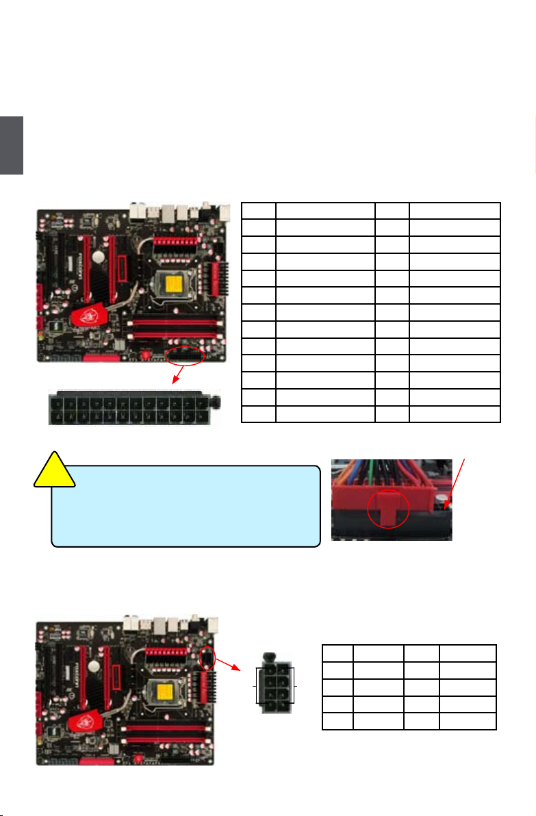
24-pin ATX Power Connector: PWR2
PWR2 is the ATX power supply connector. Make sure that the power supply cable and pins are
properly aligned with the connector on the motherboard. Firmly plug the power supply cable into the
connector and make sure it is secure.
8-pin ATX 12 V Power Connector: PWR1
Connect the 8-pin ATX 12V power supply to PWR1 and provides power to the CPU.
Pin # Denition Pin # Denition
1 3.3V 13 3.3V
2 3.3V 14 -12V
3 GND 15 GND
4 +5V 16 PS_ON(Soft On/Off)
5 GND 17 GND
6 +5V 18 GND
7 GND 19 GND
8 Power Good 20 NC
9 +5V SB(Stand by +5V) 21 +5V
10 +12V 22 +5V
11 +12V 23 +5V
12 3.3V 24 GND
We recommend you using a 24-pin power supply.
If you are using a 20-pin power supply, you need
to align the ATX power connector according to
the picture.
C
A
U
T
I
O
N
!
20-Pin Power
Pin No. 24
Pin # Denition Pin # Denition
1 GND 5 +12V
2 GND 6 +12V
3 GND 7 +12V
4 GND 8 +12V
PWR2
24
13
12
1
145
8
PWR1
GND
+12V
Page 22

15
2
15
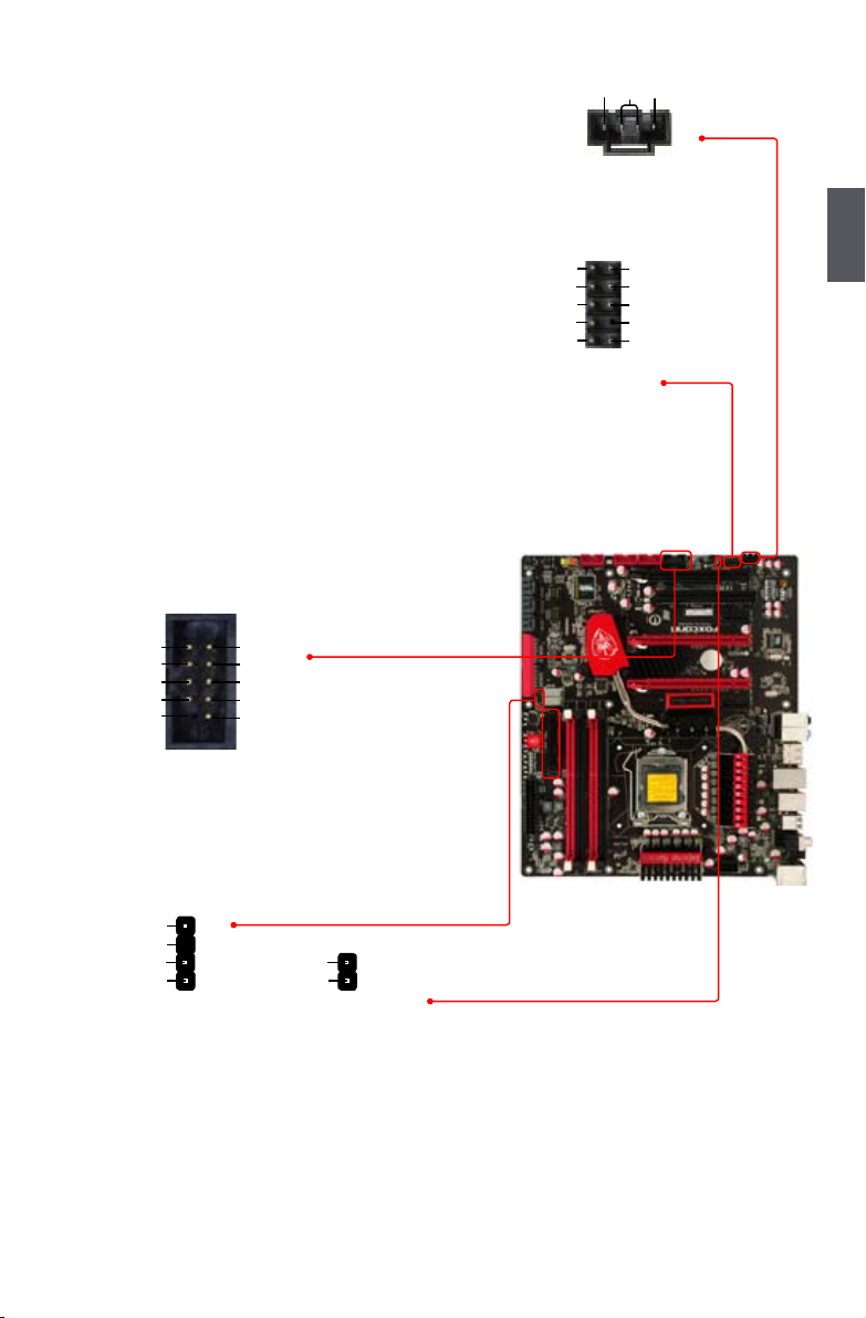
USB Connectors: F_USB1/2/3
In addition to the eight USB ports on the rear panel,
this product also provides three 10-pin USB headers on its motherboard. By connecting through USB
cables with them, user can quickly expand another
six USB ports on the front panel.
Serial ATA Connectors: SATA_1/2/3/4/5/6
The Serial ATA connector is used to connect with
SATA Hard Disk or CD devices which support this
feature. The current Serial ATA II interface allows up
to 300MB/s data transfer rate.
IDE Connector: PIDE
With the provided Ultra DMA IDE ribbon cable, you
can connect to any IDE type of hard disk and CD/
DVD ROM/RW drive.
Speaker Connector: SPEAKER
The speaker connector is used to connect speaker
of the chassis.
We recommend you using an 8-pin ATX 12V power supply. If
you are using a 4-pin power supply, you need to align the ATX
power connector according to the picture on the right.
C
A
U
T
I
O
N
!
Connect a 4-pin
power plug
1 2
109
NC
GND
VCC
D+
D-
D+
GND
D-
VCC
EMPTY
F_USB 1/2/3
SATA_1/2/3/4/5/6
GND
TX+
TXGND
RXRX+
GND
1
NC
SPKJ
EMPTY
SPEAKER
SPKJ
1
2
3
4
Page 23

16
2
16
Front Panel Connector: FP1
This motherboard includes one connector for connecting
the front panel switch and LED Indicators.
Hard Disk LED Connector (HDD-LED)
Connect to the chassis front panel IDE indicator LED. It
indicates the active status of the hard disks. This 2-pin
connector is directional with +/- sign.
Reset Switch (RESET-SW)
Attach the connector to the Reset switch on the front
panel of the case; the system will restart when the
switch is pressed.
Power LED Connector (PWR-LED)
Connect to the power LED indicator on the front panel
of the chassis. The Power LED indicates the system’s
status. When the system is in operation (S0 status),
the LED is on. When the system gets into sleep mode
(S1) , the LED is blinking; When the system is in S3/S4
sleep state or power off mode (S5), the LED is off. This
2-pin connector is directional with +/- sign.
Power Switch Connector (PWR-SW)
Connect to the power button on the front panel of the
chassis. Push this switch allows the system to be turned
on and off rather than using the power supply button.
Fan Connectors: CPU_FAN1, FAN1/2/3/4/5
There are six main fan headers on this motherboard. The
fan speed can be controlled and monitored in “PC Health
Status” section of the BIOS Setup. These fans can be
automatically turned off after the system enters
3, S4 and S5 sleeping states.
HDD-LED
RESET-SW
NC
+
-
PWR-SW
+
-
PWR-LED
EMPTY
1
2
10
9
FP1
CPU_FAN1
GND
POWER
SENSE
CONTROL
1
FAN1/2/3/4/5
GND
+12V
NC
1
Page 24
17
2
17
Audio Connector: CD_IN
CD_IN is a Sony standard audio connector, it can be
connected to a CD/DVD-ROM drive through a CD/DVD
audio cable.
Audio Connector: F_AUDIO
The audio connector supports HD Audio standard. It
provides the Front Audio output choice.
1394a Connector: F_1394 (Only for Inferno Katana)
The 1394a expansion cable can be connected to either
the front (provided that the front panel of your chassis
is equipped with the appropriate interface) or real panel
of the chassis.
S/PDIF Connector: SPDIF_OUT2/3
The connector is used for S/PDIF output.
PORT1_L
PORT1_R
PORT2_L
SENSE_SEND
SENSE1_RETURN
PRESENCEJ
EMPTY
SENSE2_RETURN
AUD_GND
1
2
109
F_AUDIO
PORT2_R
CD_IN
CD_L GND CD_R
1
SPDIF_OUT
SPDIF_OUT3
GND
1
2
SPDIF_OUT
+5V
EMPTY
SPDIF_OUT2
GND
1
2
3
4
GND
+12V
TPA-
TPB-
GND
TPB+
+12V
GND
TPA+
EMPTY
1
2
10
9
F_1394
Page 25
18
2
18
2-5 Jumpers
For some features needed, users can change the jumper settings on this motherboard to modify them.
This section explains how to use the various functions of this motherboard by changing the jumper
settings. Users should read the following content carefully prior to modifying any jumper setting.
Description of Jumpers
1. For any jumper on this motherboard, pin 1 can be identied by the bold silkscreen next to it.
However, in this manual, pin 1 is simply labeled as “1”.
2. The following table explains different types of the jumper settings. "Closed" means placing a jumper
cap on the two pins to temporarily short them. The shorting can also be done by touching two
pins by a screwdriver for a few seconds, but using jumper cap is recommended. It can prevent
hazardous ESD (Electrical Static Discharge) problem.
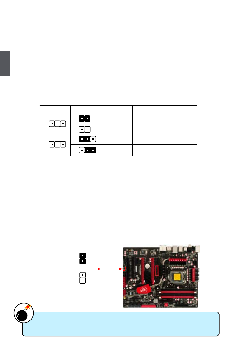
Clear CMOS Jumper: CLR_CMOS
The motherboard uses CMOS RAM to store the basic hardware information (such as BIOS data,
date, time information, hardware password...etc.). Clear CMOS data is the fast way to go back to
factory default when the BIOS settings were mistakenly modied.
The steps to clear CMOS data are :
1. Turn off the computer, unplug the power cord from the power outlet.
2.
Put a metal object(such as a screwdriver) onto pins 1-2 to short them. This will clear CMOS data.
3. After a few seconds, remove the metal object to leave the Pins 1-2 open.
4. Plug in the power cord to your computer and turn it on.
5. Go to BIOS Setup to congure new system as described in next chapter.
Jumper Diagram Denition Description
1-2 Set Pin 1 and Pin 2 closed
1-2 Set Pin 1 and Pin 2 Open
1-2 Set Pin 1 and Pin 2 closed
2-3 Set Pin 2 and Pin 3 closed
Clear
1
2
Normal
(Default)
1
2
CLR_CMOS
■ Disconnect the power cable before adjusting the jumper settings.
■ Do not clear the CMOS while the system is turned on.
W
A
R
N
I
N
G
!
1
1
1
1
1
1
Page 26

19
2
19
■ Make sure the power supply is turned off before pressing the CLS_CMOS button to
clear CMOS.
■ Push down the CLS_CMOS button and hold it there for a couple of seconds to clear
the CMOS completely, then release.
C
A
U
T
I
O
N
!
2-6 OnBoard Button
Power on Button: PWR_ON
Push the power on button to power on the system.
Reset Button: RST
Push the reset button to reboot the system.
Clear CMOS Button: CLS_CMOS2
Turn off the AC power supply, push the CLS_CMOS
button and hold there for a couple of seconds to clear
CMOS.
Force Reset Button: FORCE_RESET (Only for
Inferno Katana)
Simply rebooting after applying new OC settings can
cause the system to fail because the hardware has not
been reset properly. But with one press on the Force
Reset button, your system will not only re-boot, but also
re-tune itself! This button triggers the CPU, memory
controller and chipset to re-initialize, running hardware
checks and timing algorithms before reloading with your
new overclocking settings. This reduces instances of
failed re-boots after implementing OC settings.
POWER_ON CLS_CMOSRESET
2-7 OnBoard Debug LED
2-digital LED readout displays hardware status and
enables quick error diagnosis.
FORCE_RESET
Page 27
20
2
20
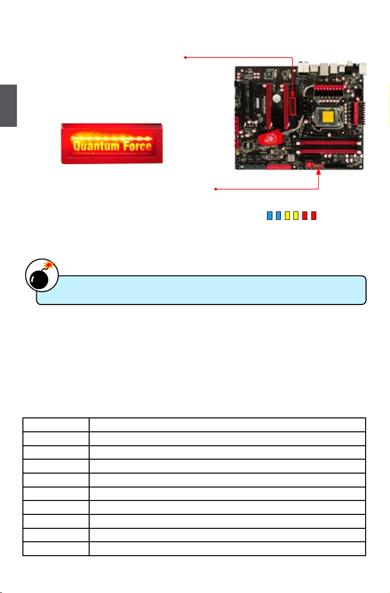
2-8 OnBoard LED
Core Nerve (Only for Inferno Katana):
There are ten LEDs under the “Quantum Force” light.
Their ashing frequency is following the power loading.
The power loading is heavier, the leds ash faster. User
can check the loading in time through this light.
Fuzzy Equalizer (Only for Inferno Katana):
Fuzzy Equalizer can offer efcient power when user need
it. It identies one LED reprsents two phases power. All
the six LEDs ashing means the motherboard are using
twelve phases power.
Do not remove or plug in any device when the onboard LED is lighting on.
W
A
R
N
I
N
G
!
2-9 BIOS Debug Code Description
1. i-Tweaker BIOS Debug Code
a. It means that DebugCode appear to 7 segment LEDs by i-Tweaker when you can see two
DOT symbols such as 5.0. at 7’seg LEDs, otherwise is BIOS debug code.
b. i-Tweaker rst debug code is meaning of PCB version that i-Tweaker can supported.
Ex: A.A. means PCB A, B.B. means PCB B… etc.
c. i-Tweaker second debug code is meaning of i-Tweaker version. It should be combined with
PCB version such as AA01, AA02, BB01, BB02 and etc.
Debug Code Description
0.0. i-Tweaker AC Ready.
5.0. All ready. Wait for power button click to boot machine.
5.1. On power sequence, but power button event fail.
5.2. On power sequence, wait S_SLP_S4 event.
5.3. On power sequence, wait S_SLP_S3 event.
5.4. On power sequence, pass S_SLP_S3 and S_SLP_S4 event.
5.5. On power sequence, but 1.8V PLL cannot ready.
5.6. On power sequence, when 1.8V PLL is ready.
5.7. On power sequence, but Vdimm cannot ready.
Core Nerve
Fuzzy Equalizer
Page 28

21
2
21
5.8. On power sequence, when Vdimm is ready.
5.9. On power sequence, but 1.05V PCH cannot ready.
5.A. On power sequence, when 1.05V PCH is ready.
5.B. On power sequence, but 1.1V VTT cannot ready.
5.D. On power sequence, when 1.1V VTT is ready.
5.F. On power sequence, but ATXPWROK cannot ready.
6.0. On power sequence, when ATXPWROK is ready.
6.1. On power sequence, but Vcore cannot ready.
6.6. Power sequence nished.
2. AMI BIOS8TM Check Point
1. Bootblock Initialization Code Checkpoints
The Bootblock initialization code sets up the chipset, memory and other components before
system memory is available. The following table describes the type of checkpoints that may
occur during the bootblock initialization portion of the BIOS:
Checkpoint Description
Before D0 If boot block debugger is enabled, CPU cache-as-RAM functionality is
enabled at this point. Stack will be enabled from this point.
D0 Early Boot Strap Processor (BSP) initialization like microcode update,
frequency and other CPU critical initialization. Early chipset initialization is
done.
D1 Early super I/O initialization is done including RTC and keyboard controller.
Serial port is enabled at this point if needed for debugging. NMI is disabled.
Perform keyboard controller BAT test. Save power-on CPUID value in scratch
CMOS. Go to at mode with 4GB limit and GA20 enabled.
D2 Verify the boot block checksum. System will hang here if checksum is bad.
D3 Disable CACHE before memory detection. Execute full memory sizing
module. If memory sizing module not executed, start memory refresh and do
memory sizing in Boot block code. Do additional chipset initialization.
Re-enable CACHE. Verify that at mode is enabled.
D4 Test base 512KB memory. Adjust policies and cache rst 8MB. Set stack.
D5 Bootblock code is copied from ROM to lower system memory and control is
given to it. BIOS now executes out of RAM. Copies compressed boot block
code to memory in right segments. Copies BIOS from ROM to RAM for faster
access. Performs main BIOS checksum and updates recovery status
accordingly.
Checkpoints may differ between different platforms based on system conguration.
Checkpoints may change due to vendor requirements, system chipset or option ROMs
from add-in PCI devices.
C
A
U
T
I
O
N
!
Page 29

22
2
22
D6 Both key sequence and OEM specic method is checked to determine
if BIOS recovery is forced. If BIOS recovery is necessary, control ows
to checkpoint E0. See Bootblock Recovery Code Checkpoints section of
document for more information.
D7 Restore CPUID value back into register. The Bootblock-Runtime interface
module is moved to system memory and control is given to it. Determine
whether to execute serial ash.
D8 The Runtime module is uncompressed into memory. CPUID information is
stored in memory.
D9
Store the Uncompressed pointer for future use in PMM. Copying Main BIOS
into memory. Leaves all RAM below 1MB Read-Write including E000 and F000
shadow areas but closing SMRAM.
DA
Restore CPUID value back into register. Give control to BIOS POST(Execute
POST Kernel). See POST Code Checkpoints section of document for more
information.
DC
System is waking from ACPI S3 state.
E1-E8
EC-EE
OEM memory detection/conguration error. This range is reserved for chipset
vendors & system manufacturers. The error associated with this value may be
different from one platform to the next.
2. Bootblock Recovery Code Checkpoints
The Bootblock recovery code gets control when the BIOS determines that a BIOS recovery needs
to occur because the user has forced the update or the BIOS checksum is corrupt. The following
table describes the type of checkpoints that may occur during the Bootblock recovery portion of
the BIOS:
Checkpoint Description
E0 Initialize the oppy controller in the super I/O. Some interrupt vectors are
initialized. DMA controller is initialized. 8259 interrupt controller is initialized.
L1 cache is enabled.
E9 Set up oppy controller and data. Attempt to read from oppy.
EA Enable ATAPI hardware. Attempt to read from ARMD and ATAPI CDROM.
EB Disable ATAPI hardware. Jump back to checkpoint E9.
EF Read error occurred on media. Jump back to checkpoint EB.
F0 Search for pre-dened recovery le name in root directory.
F1 Recovery le not found.
F2 Start reading FAT table and analyze FAT to nd the clusters occupied by the
recovery le.
F3 Start reading the recovery le cluster by cluster.
F5 Disable L1 cache.
FA Check the validity of the recovery le conguration to the current conguration
of the ash part.
Page 30

23
2
23
FB Make ash write enabled through chipset and OEM specic method. Detect
proper ash part. Verify that the found ash part size equals the recovery
le size.
F4 The recovery le size does not equal the found ash part size.
FC Erase the ash part.
FD Program the ash part.
FF The ash has been updated successfully. Make ash write disabled.
Disable ATAPI hardware. Restore CPUID value back into register. Give
control to F000 ROM at F000:FFF0h.
3. POST Code Checkpoints
The POST code checkpoints are the largest set of checkpoints during the BIOS preboot
process. The following table describes the type of checkpoints that may occur
during the POST portion of the BIOS:
Checkpoint Description
03 Disable NMI, Parity, video for EGA, and DMA controllers. Initialize BIOS,
POST, Runtime data area. Also initialize BIOS modules on POST entry
and GPNV area. Initialized CMOS as mentioned in the Kernel Variable
“wCMOSFlags.”
04 Check CMOS diagnostic byte to determine if battery power is OK and CMOS
checksum is OK. Verify CMOS checksum manually by reading storage area. If
the CMOS checksum is bad, update CMOS with power-on default values and
clear passwords. Initialize status register A. Initializes data variables that are
based on CMOS setup questions.
Initializes both the 8259 compatible PICs in the system.
05 Initializes the interrupt controlling hardware (generally PIC) and interrupt
vector table.
06 Do R/W test to CH-2 count reg. Initialize CH-0 as system timer. Install the
POSTINT1Ch handler. Enable IRQ-0 in PIC for system timer interrupt.
Traps INT1Ch vector to “POSTINT1ChHandlerBlock.”
07 Fixes CPU POST interface calling pointer.
08 Initializes the CPU. The BAT test is being done on KBC. Program the
keyboard controller command byte is being done after Auto detection of
KB/MS using AMI KB-5.
C0 Early CPU Init Start -- Disable Cache – Init Local APIC.
C1 Set up boot strap processor Information.
C2 Set up boot strap processor for POST.
C5 Enumerate and set up application processors.
C6 Re-enable cache for boot strap processor.
C7 Early CPU Init Exit.
0A Initializes the 8042 compatible Key Board Controller.
0B Detects the presence of PS/2 mouse.
0C Detects the presence of Keyboard in KBC port.
Page 31

24
2
24
0E Testing and initialization of different Input Devices. Also, update the
Kernel Variables.
Traps the INT09h vector, so that the POST INT09h handler gets control for
IRQ1. Uncompress all available language, BIOS logo, and Silent logo
modules.
13 Early POST initialization of chipset registers.
20 Relocate System Management Interrupt vector for all CPU in the system.
24 Uncompress and initialize any platform specic BIOS modules. GPNV is
initialized at this checkpoint.
2A Initializes different devices through DIM.
See DIM Code Checkpoints section of document for more information.
2C Initializes different devices. Detects and initializes the video adapter
installed in the system that have optional ROMs.
2E Initializes all the output devices.
31 Allocate memory for ADM module and uncompress it. Give control to ADM
module for initialization. Initialize language and font modules for ADM.
Activate ADM module.
33 Initializes the silent boot module. Set the window for displaying text
information.
37 Displaying sign-on message, CPU information, setup key message, and any
OEM specic information.
38 Initializes different devices through DIM. See DIM Code Checkpoints
section of document for more information. USB controllers are initialized
at this point.
39 Initializes DMAC-1 & DMAC-2.
3A Initialize RTC date/time.
3B Test for total memory installed in the system. Also, Check for DEL or ESC
keys to limit memory test. Display total memory in the system.
3C Mid POST initialization of chipset registers.
40 Detect different devices (Parallel ports, serial ports, and coprocessor in CPU,
… etc.) successfully installed in the system and update the BDA, EBDA…etc.
52 Updates CMOS memory size from memory found in memory test. Allocates
memory for Extended BIOS Data Area from base memory. Programming
the memory hole or any kind of implementation that needs an adjustment
in system RAM size if needed.
60 Initializes NUM-LOCK status and programs the KBD typematic rate.
75 Initialize Int-13 and prepare for IPL detection.
78 Initializes IPL devices controlled by BIOS and option ROMs.
7C Generate and write contents of ESCD in NVRam.
84 Log errors encountered during POST.
85 Display errors to the user and gets the user response for error.
Page 32

25
2
25
87 Execute BIOS setup if needed / requested. Check boot password if
installed.
8C Late POST initialization of chipset registers.
8D Build ACPI tables (if ACPI is supported)
8E Program the peripheral parameters. Enable/Disable NMI as selected
90 Initialization of system management interrupt by invoking all handlers.
Please note this checkpoint comes right after checkpoint 20h
A1 Clean-up work needed before booting to OS.
A2 Takes care of runtime image preparation for different BIOS modules. Fill
the free area in F000h segment with 0FFh. Initializes the Microsoft IRQ
Routing Table. Prepares the runtime language module. Disables the
system conguration display if needed.
A4 Initialize runtime language module. Display boot option popup menu.
A7 Displays the system conguration screen if enabled. Initialize the CPU’s
before boot, which includes the programming of the MTRR’s.
A9 Wait for user input at cong display if needed.
AA Uninstall POST INT1Ch vector and INT09h vector.
AB Prepare BBS for Int 19 boot. Init MP tables.
AC End of POST initialization of chipset registers. De-initializes the ADM
module.
B1 Save system context for ACPI. Prepare CPU for OS boot including nal
MTRR values.
00 Passes control to OS Loader (typically INT19h).
4. ACPI Runtime Checkpoints
ACPI checkpoints are displayed when an ACPI capable operating system either enters
or leaves a sleep state. The following table describes the type of checkpoints that
may occur during ACPI sleep or wake events:
Checkpoint Description
AC First ASL check point. Indicates the system is running in ACPI mode.
AA System is running in APIC mode.
01, 02, 03,
04, 05
Entering sleep state S1, S2, S3, S4, or S5.
10, 20, 30,
40, 50
Waking from sleep state S1, S2, S3, S4, or S5.
Page 33

This chapter tells how to change system settings through
the BIOS Setup menus. Detailed descriptions of the BIOS
parameters are also provided.
You have to run the Setup Program when the following cases
occur :
1. An error message appears on the screen during the system
Power On Self Test (POST) process.
2. You want to change the default CMOS settings.
This chapter includes the following information :
■ Enter BIOS Setup
■ Main Menu
■ System Information
■ Advanced BIOS Features
■ Advanced Chipset Features
■ Boot Conguration Features
■ Power Management Setup
■ PC Health Status
■ Quantum BIOS
■ BIOS Security Features
■ Load Optimal Defaults
■ Save & Exit Setup
■ Exit Without Saving
Since BIOS could be updated some other times, the BIOS information described
in this manual is for reference only. We do not guarantee the content of this
manual will remain consistent with the newly released BIOS at any given time in
the future. Please visit our website for updated manual if it is available.
Page 34

3
27
Enter BIOS Setup
The BIOS is the communication bridge between hardware and software, correctly setting up the
BIOS parameters is critical to maintain optimal system performance. Power on the computer,
when the message "Press Tab to show POST screen, DEL to enter SETUP" appears at the
bottom of the screen, you can press <DEL> key to enter Setup.
Main Menu
The main menu allows you to select from a list of setup functions together with two exit choices.
Use the arrow keys to select a specic item and press <Enter> to go to the sub-menu.
Each item in the main menu is explained below:
► System Information
It displays the basic system conguration, such as BIOS ID, CPU information, memory size
and system date, time. They all can be viewed or set up through this menu.
► Advanced BIOS Features
Advanced settings can be set up through this menu. There are IDE conguration, AHCI con-
guration and MPS conguration.
► Advanced Chipset Features
Chipset features, USB functions and some onBoard devices values can be set up through this
menu.
► Boot Configuration Features
Boot features can be set up through this menu. You can enable or disable "Quick Boot" and
"Quiet Boot" feature here.
CMOS Setup Utility - Copyright (C) 1985-2009, American Megatrends, Inc.
► System Information ► Quantum BIOS
► Advanced BIOS Features ► BIOS Security Features
► Advanced Chipset Features Load Optimal Defaults
► Boot Configuration Features Save & Exit Setup
► Power Management Setup Exit Without Saving
► PC Health Status
↑↓←→:Move Enter:Select +/-/:Value F10:Save ESC:Exit F1:General Help
F9:Optimized Defaults
Configure Time and Date. Display System Information...
v02.67 (C) Copyright 1985-2009, American Megatrends, Inc.
► System Information
We do not suggest that you change the default values in the BIOS Setup, and we
shall not be responsible for any damage which resulted from the change you made.
C
A
U
T
I
O
N
!
Page 35

3
28
► Power Management Setup
All the items related with Green function features can be setup through this menu.
► PC Health Status
This setup enables you to read/change fan speeds, and displays temperatures and voltages of
your CPU/System.
► Quantum BIOS
Some special proprietary features (such as overclocking) can be set up through this menu.
► BIOS Security Features
The Supervisor/User password can be set up through this menu to prevent unauthorized use
of your computer. If you set a password, the system will ask you to key in correct password
before boot or access to Setup.
► Load Optimal Defaults
The optimal performance settings can be loaded through this menu. However, it may offer bet-
ter performance in some ways (such as less I/O cards, less memory ...etc.), still, it may cause
problem if you have more memory or I/O cards installed. It means, if your system loading is
heavy, set to optimal default may sometimes come out an unstable system. What you need
now is to adjust BIOS setting one by one, trial and error, to nd out the best setting for your
current system.
► Save & Exit Setup
Save setting values to CMOS and exit.
► Exit Without Saving
Do not change anything and exit the setup.
Page 36

3
29
System Information
This sub-menu is used to set up the standard BIOS features, such as the date, time, memory and
so on. Use the arrow up/down keys to select an item, then use the <+> or <-> keys to change the
setting.
System Overview
► System Time
This item allows you to congure the desired time. Use [ENTER], [TAB] or [SHIFT-TAB] to
select a eld. Use [+] or [-] to input the value.
The three elds of the setting are <hour> : <minute> : <second> respectively.
► System Date
<weekday><month><date> <year> format.
Day—weekday from Sun. to Sat., this message is automatically displayed by BIOS (Read
Only).
Month—month from 1 to 12.
Date—date from 1 to 31.
Year—year, set up by users.
Use [ENTER], [TAB] or [SHIFT-TAB] to select a eld. Use [+] or [-] to input the value.
AMIBIOS
► BIOS Version
It displays the current BIOS version. User can check this information and discuss with the eld
service people if a BIOS upgrade is needed.
► BIOS Build Date
This item shows the BIOS building date.
► BIOS ID
This item shows the BIOS ID.
Processor
► Speed
It displays the current CPU speed.
► Count
It shows the CPU numbers.
CMOS Setup Utility - Copyright (C) 1985-2009, American Megatrends, Inc.
System Information
System Overview Help Item
System Time
00:50:11 Use [ENTER], [TAB]
System Date Tue 07/21/2009 or [SHIFT-TAB] to
select a eld.
AMIBIOS
BIOS Version :08.00.15 Use [+] or [-] to
BIOS Bulid Date :07/21/09 congure system time.
BIOS ID :934F1D06
Processor
Speed :2933MHz
Count :4
System Memory
System Memory Size :1024MB
OnBoard LAN MAC Address :00-E0-4C-68-00-03
↑↓←→:Move Enter:Select +/-/:Value F10:Save ESC:Exit F1:General Help
F9:Optimized Defaults
00
Page 37

3
30
System Memory
► System Memory Size
This item displays the current memory size. The size is depending on how many memory mod-
ules were installed in your system before powering on.
► OnBoard LAN MAC Address
This item shows the onboard LAN MAC address.
Page 38

3
31
Advanced BIOS Features
► IDE Conguration/ACHI Conguration/MPS Conguration
Press <Enter> to go to relative submenu.
IDE Conguration
► Configure SATA as
This item is used to set the operation mode of your SATA ports 1, 2, 3, 4, 5, 6. Setting values
are: [IDE]; [RAID]; [AHCI]; [Disabled].
[IDE] - This congures the SATA ports to support IDE mode.
[RAID] - When you enable RAID, it means all your SATA drives must also support AHCI.
[AHCI] - The Advanced Host Controller Interface (AHCI) specication describes the register
level interface for a Host Controller for Serial ATA. The specication includes a description of
the hardware/software interface between system software and the host controller hardware.
CMOS Setup Utility - Copyright (C) 1985-2009, American Megatrends, Inc.
Advanced BIOS Features
Advanced Settings Help Item
► IDE conguration
Press Enter Configure the IDE
► AHCI Conguration
Press Enter device(s).
► MPS Conguration Press Enter
↑↓←→:Move Enter:Select +/-/:Value F10:Save ESC:Exit F1:General Help
F9:Optimized Defaults
Press Enter
CMOS Setup Utility - Copyright (C) 1985-2009, American Megatrends, Inc.
IDE Conguration
IDE Configuration Help Item
Congure SATA as IDE
SATA#1 IDE Conguration Compatible
SATA#2 IDE Conguration Enhanced IDE
RAID
► Primary IDE Master Not Detected
AHCI
► Primary IDE Slave Not Detected
Disabled
► Secondary IDE Master Not Detected
► Secondary IDE Slave Not Detected
► Third IDE Master Not Detected
► Fourth IDE Master
Not Detected
Hard Disk Write Protect Disabled
IDE Detect Time Out 35
ATA(PI) 80Pin Cable Detect Host & Device
↑↓←→:Move Enter:Select +/-/:Value F10:Save ESC:Exit F1:General Help
F9:Optimized Defaults
Options
IDE
Page 39

3
32
AHCI provides more advanced features including SATA features, but some SATA drives may
not support AHCI, unless they are labeled with AHCI support in its specication.
If your motherboard supporting AHCI, and you have a SATA device, which also supports AHCI,
then you can select IDE option to have fair performance (only PATA, SATA level), or you can
select AHCI to get its best performance.
► SATA#1 IDE Configuration
SATA#1 are the SATA ports 1, 2, 3, 4 of the motherboard. This item allows you select the
mode of the SATA ports. Setting values are: [Compatible], [Enhanced].
► SATA#2 IDE Configuration
SATA#2 are the SATA ports 5,6 of the motherboard. This item allows you select the mode of
the SATA ports. Setting values are: [Disabled], [Enhanced].
► Primary/Secondary IDE Master/Slave, Third/Fourth IDE Master
While entering setup, BIOS automatically detects the presence of IDE devices. This item
displays the drive information of IDE devices.
► Hot Plug (Appears when “Configure SATA as” is set to[RAID]/[AHCI])
This item is used to enable or disable hot plug function for SATA hard disks when in RAID/
AHCI mode.
► Hard Disk Write Protect
This item is used to disable/enable device write protection. This will be effective only if device
is accessed through BIOS.
► IDE Detect Time Out
This item is used to select the time out value for detecting ATA/ATAPI devices. If the checking
time is over the set value, the system will skip it.
► ATA(PI) 80Pin Cable Detect
This item is used to select the mechanism for detecting 80Pin ATA(PI) Cable. The default
value is: [Host & Device].
Page 40

3
33
AHCI Conguration
AHCI Settings
► AHCI BIOS Support
The Advanced Host Controller Interface (AHCI) specication describes the register level
interface for a Host Controller for Serial ATA. The specication includes a description of the
hardware/software interface between system software and the host controller hardware. AHCI
provides more advanced features including SATA features, but some SATA drives may not
support AHCI, unless they are labeled with AHCI support in its specication.
This item is used to enable or disable your motherboard to support the AHCI specication.
► AHCI Port0/1/2/3/4/5
These options display the status of IDE devices. BIOS auto detects the presence of IDE
devices while entering setup.
CMOS Setup Utility - Copyright (C) 1985-2009, American Megatrends, Inc.
AHCI Conguration
AHCI Settings Help Item
AHCI BIOS Support Enables for supporting
► AHCI Port0 Not Detected
► AHCI Port1
Not Detected
► AHCI Port2
Not Detected
► AHCI Port3
Not Detected
► AHCI Port4
Not Detected
► AHCI Port5
Not Detected
↑↓←→:Move Enter:Select +/-/:Value F10:Save ESC:Exit F1:General Help
F9:Optimized Defaults
Enabled
Page 41

3
34
MPS Conguration
► MPS Revision
This feature is only applicable to multiprocessor motherboards as it species the version of
the MPS that the motherboard will use. The MPS is a specication by which PC manufactur-
ers design and build CPU architecture systems with two or more processors. MPS 1.1 was
the original specication. MPS version 1.4 adds extended conguration tables for improved
support of multiple PCI bus congurations and greater expandability in the future. In addition,
MPS 1.4 introduces support for a secondary PCI bus without requiring a PCI bridge. If your
operating system comes with support for MPS 1.4, you should keep the setting as the default
1.4. You also need to enable MPS 1.4 support if you need to make use of the secondary PCI
bus on a motherboard that doesn't come with a PCI bridge. You should only leave it as 1.1
only if you are running an older operation system that only supports MPS 1.1.
CMOS Setup Utility - Copyright (C) 1985-2009, American Megatrends, Inc.
MPS Conguration
MPS Configuration Help Item
MPS Revision Select MPS Revision.
↑↓←→:Move Enter:Select +/-/:Value F10:Save ESC:Exit F1:General Help
F9:Optimized Defaults
1.4
Page 42

3
35
Advanced Chipset Features
► North Bridge Conguration/ South Bridge Conguration/OnBoard Device Conguration/
USB Conguration
Press <Enter> to go to relative submenu.
North Bridge Conguration
North Bridge Chipset Conguration
► Memory Hole
This item is used to enable/disable memory hole. The setting values are: [Disabled], [15MB-16MB].
► Initate Graphic Adapter
This item is used to select which graphics controller is used as the primary boot device.
CMOS Setup Utility - Copyright (C) 1985-2009, American Megatrends, Inc.
Advanced Chipset Features
Advanced Chipset Settings Help Item
► North Bridge Conguration
Press Enter Configure North Bridge
► South Bridge Conguration
Press Enter features.
► OnBoard Device Conguration
Press Enter
► USB Conguration
Press Enter
↑↓←→:Move Enter:Select +/-/:Value F10:Save ESC:Exit F1:General Help
F9:Optimized Defaults
Press Enter
CMOS Setup Utility - Copyright (C) 1985-2009, American Megatrends, Inc.
North Bridge Conguration
North Bridge Chipset Conguration Help Item
IMC Type : Havendale
Memory Hole Disabled
15MB-16MB
Initate Graphic Adapter PCIE/PCI
↑↓←→:Move Enter:Select +/-/:Value F10:Save ESC:Exit F1:General Help
F9:Optimized Defaults
Disabled
Options
Page 43

3
36
South Bridge Conguration
South Bridge Chipset Conguration
► SMBUS Controller
The System Management Bus is a specic implementation of an I2C bus. The SMBus speci-
cation describes the data protocols, device addresses, and electrical requirements that are
superimposed on the I2C bus specication. The SMBus is used to physically transport com-
mands and information between the Smart Battery, SMBus Host, Smart Battery Charger, and
other SMBus Devices. This item is used to enable/disable System Mangement Bus controller.
► Debug Code Control
This item allows you to select debug code control mode. Select "LPC", you can use onboard
seven segment LED; Select "PCI", you must insert debug card into PCI slot.
► SLP_S4# Min. Assertion Width
SLP_S4# is a signal for power plane control. This signal shuts off power to all non-critical
systems when in the S4 (Suspend to Disk) or S5 (Soft Off) state.
This setting indicates the minimum assertion width of the SLP_S4# signal to ensure that the
DRAMs have been safely power-cycled. Setting values are: [4 to 5 seconds], [3 to 4 seconds],
[2 to 3 seconds], [1 to 2 seconds].
► PCIE Ports Conguration
PCIE Port 0/1/2/3/4
This option is used to enable or disable the PCI Express port. Setting to [Auto] allows the
system to detect the PCI Express devices automatically. If detected, the PCI Express Port is
enabled, or else the PCI Express Port is disabled.
CMOS Setup Utility - Copyright (C) 1985-2009, American Megatrends, Inc.
South Bridge Conguration
South Bridge Chipset Conguration Help Item
SMBUS Controller
Enabled
Debug Code Control LPC Enabled
SLP_S4# Min. Assertion Width 4 to 5 seconds Disabled
PCIE Ports Conguration
PCIE Port 0 Auto
PCIE Port 1 Auto
PCIE Port 2 Auto
PCIE Port 3 Auto
PCIE Port 4 Auto
↑↓←→:Move Enter:Select +/-/:Value F10:Save ESC:Exit F1:General Help
F9:Optimized Defaults
Enabled
Options
Page 44

3
37
OnBoard Device Conguration
► HDA Controller
This item is used to enable or disable the HD Audio controller.
► VIA 6308S 1394 Device
This item is used to enable or disable the VIA 6308S 1394 device.
► Realtek 8111D LAN Device
This item is used to enable or disable the Realtek 8111D LAN device.
► Realtek 8111D LAN BootROM
This item is used to enable or disable the Realtek 8111D LAN BootROM.
► Marvell 6121 PATA and eSATA
You may set your PATA and e-SATA to [eSATA+IDE] mode or [RAID+IDE] Mode (RAID for e-SATA,
IDE for PATA). We are using Marvell chip to control PATA and e-SATA devices.
CMOS Setup Utility - Copyright (C) 1985-2009, American Megatrends, Inc.
OnBoard Device Conguration
OnBoard Device Conguration Help Item
HDA Controller
Enabled
VIA 6308S 1394 Device Enabled
Realtek 8111D LAN Device Enabled Enabled
Realtek 8111D LAN BootROM Disabled Disabled
Marvell 6121 PATA and eSATA eSATA + IDE
↑↓←→:Move Enter:Select +/-/:Value F10:Save ESC:Exit F1:General Help
F9:Optimized Defaults
Enabled
Options
Page 45

3
38
USB Conguration
USB Conguration
► USB Functions
This item is used to enable or disable USB function.
► Legacy USB Support
This item is used to enable the support for USB devices on legacy OS. If you have a USB
keyboard or mouse, set to auto or enabled.
► USB 2.0 Controller Mode
This item is used to set the transmission rate mode of USB 2.0. The available settings are :
[High Speed] in 480Mbps; [Full Speed] in 12Mbps.
► BIOS EHCI Hand-Off
Windows XP supports a number of features in the Enhanced Host Controller Interface (EHCI)
specication, but there are a few features that are not implemented. Microsoft said preliminary
support for EHCI BIOS handoff will be available in Windows XP SP2.
This item allows you to enable support for OS without EHCI hand-off feature.
This is a workaround for OS without EHCI hand-Off support .
The EHCI ownership change should claim by EHCI driver.
If USB mass devices are connected to the computer, the following item will appear:
► USB Mass Storage Device
After pressing <Enter>, you can set the reset delay for the USB mass storage device. There
are many different emulation types of this USB device, such as [Auto], [Floppy], [Forced FDD],
[Hard Disk] and [CDROM] can be selected. Select [Auto], USB devices less than 530MB will
be emulated as Floppy and remaining as hard drive. [Forced FDD] option can be used to force
a HDD formatted drive to boot as FDD(Ex. ZIP drive).
CMOS Setup Utility - Copyright (C) 1985-2009, American Megatrends, Inc.
USB Conguration
USB Conguration Help Item
Module Version - 2.24.3-13.4
USB Devices Enabled : Disabled
None 2 USB Ports
4 USB Ports
USB Functions 14 USB Ports 6 USB Ports
Legacy USB Support Enabled 8 USB Ports
USB 2.0 Controller Mode High Speed 10 USB Ports
BIOS EHCI Hand-Off Enabled 12 USB Ports
14 USB Ports
↑↓←→:Move Enter:Select +/-/:Value F10:Save ESC:Exit F1:General Help
F9:Optimized Defaults
14 USB Ports
Options
Page 46

3
39
Boot Conguration Features
► Boot Settings Conguration
Press <Enter> to go to relative submenu.
► Boot Device Priority
This item is used to specify the boot device priority sequence.
► Network Drives
This option is used to specify the boot device priority sequence from available Network Drives.
CMOS Setup Utility - Copyright (C) 1985-2009, American Megatrends, Inc.
Boot Conguration Features
Boot Settings Help Item
► Boot Settings Conguration Congure Settings
during System Boot.
► Boot Device Priority
[Press Enter]
► Network Drives [Press Enter]
↑↓←→:Move Enter:Select +/-/:Value F10:Save ESC:Exit F1:General Help
F9:Optimized Defaults
[Press Enter]
Page 47

3
40
Boot Settings Conguration
► Quick Boot
While Enabled, this option allows BIOS to skip certain tests while booting, this will shorten the
time needed to boot the system.
► Quiet Boot
This item is used to enable/disable the quiet boot.
[Disabled] : Displays the normal POST messages.
[Enabled] : Displays OEM customer logo instead of POST messages.
► Bootup Num-Lock
This item denes if the keyboard Num Lock key is active when your system is started. The
available settings are: [On] (default) and [Off].
► Wait For ‘F1’ If Error
You can set whether to press [F1] key if error occurs in the POST(Power On Self Test).
► Hit ‘DEL’ Message Display
This item is used to enable or disable system dispalys the “Press DEL to Enter Setup” in POST.
► Interrupt 19 Capture
When set to [Enabled], BIOS allows option ROMS to trap interrupt 19.
CMOS Setup Utility - Copyright (C) 1985-2009, American Megatrends, Inc.
Boot Settings Conguration
Boot Settings Conguration Help Item
Quick Boot Enabled Allows BIOS to Skip
Quiet Boot Enabled certain tests while
Bootup Num-Lock On booting. This will
Wait For ‘F1’ If Error Enabled decrease the time
Hit ‘DEL’ Message Display Enabled needed to boot the
Interrupt 19 Capture Disabled system.
↑↓←→:Move Enter:Select +/-/:Value F10:Save ESC:Exit F1:General Help
F9:Optimized Defaults
Enabled
Page 48

3
41
Power Management Setup
ACPI (Advanced Conguration and Power Interface) is an open industry standard interfaces
enabling OS-directed conguration, power management, and thermal management of mobile,
desktop, and server platforms. It denes ve sleeping states, they are :
S1 - The S1 sleeping state is a low wake latency sleeping state. In this state, no system
context is lost (CPU or chip set) and hardware maintains all system context. (also called
Power On Suspend)
S2 - The S2 sleeping state is a low wake latency sleeping state. This state is similar to the S1
sleeping state except that the CPU and system cache context is lost (the OS is respon-
sible for maintaining the caches and CPU context). Control starts from the processor’s
reset vector after the wake event.
S3 - The S3 sleeping state is a low wake latency sleeping state where all system context is lost
except system memory. CPU, cache, and chip set context are lost in this state. Hardware
maintains memory context and restores some CPU and L2 conguration context. Control
starts from the processor’s reset vector after the wake event. (also called Suspend to
RAM)
S4 - The S4 sleeping state is the lowest power, longest wake latency sleeping state supported
by ACPI. In order to reduce power to a minimum, it is assumed that the hardware platform
has powered off all devices. Platform context is maintained. (also called Suspend to
Disk)
S5 - The S5 state is similar to the S4 state except that the OS does not save any context. The
system is in the “soft” off state and requires a complete boot when it wakes. Software
uses a different state value to distinguish between the S5 state and the S4 state to allow
for initial boot operations within the BIOS to distinguish whether or not the boot is going to
wake from a saved memory image.
► Suspend mode
This item is used to set the energy saving mode of the ACPI function. When you select “S1
(POS)” mode, the power is always on and computer can be resumed at any time. When
you select “S3 (STR)” mode, the power will be down after a period of time. The status of the
CMOS Setup Utility - Copyright (C) 1985-2009, American Megatrends, Inc.
Power Management Setup
Power Management Setup Help Item
Suspend mode Auto Select the ACPI
Repost Video on S3 Resume No state used for
ACPI Version Features
ACPI v1.0 System Suspend.
ACPI APIC Support Enabled
AMI OEMB table Enabled
Headless mode Disabled
APIC ACPI SCI IRQ Disabled
Wake-Up by PCIe Card Disabled
Wake-Up by PCI Card Disabled
Wake-Up by OnBoard LAN Disabled
USB Device Wakeup From S3/S4 Disabled
High Performance Event Timer Disabled
Active State Power-Management Disabled
Wake-Up by PS2 K/B Any Key Disabled
Power loss Recovery Always Off
↑↓→←:Move Enter:Select +/-/:Value F10:Save ESC:Exit F1:General Help
F9:Optimized Defaults
Auto
Page 49

3
42
computer before it entering STR will be saved in memory, and the computer can quickly return
to previous state when the STR function wakes.
When you select “Auto”, it means OS will automatically take care and assign which mode is
the most suitable now.
► Repost Video on S3 Resume
This item determines whether to invoke VGA BIOS post on S3/STR resume.
► ACPI Version Features
This item is used to select the ACPI Version feature, setting values: [ACPI v1.0], [ACPI v2.0]
and [ACPI v3.0].
► ACPI APIC support
This item is used to enable or disable the ACPI APIC.
► AMI OEMB table
This item is used to enable or disable the AMI OEM BIOS table.
► Headless mode
This item is used to enable or disable Headless operation mode through ACPI.
► APIC ACPI SCI IRQ
This item is used to enable or disable the APIC ACPI SCI IRQ.
► Wake-Up by PCIe Card
This item is used to wake up the system by PCIe card
► Wake-Up by PCI Card
This item is used to wake up the system by PCI card.
► Wake-Up by OnBoard LAN
This item is used to wake up the system by OnBoard LAN device.
► USB Device Wakeup From S3/S4
This item is used to wake up the system by a USB device when it is staying at S3/S4 state.
► High Performance Event Timer
This item is used to enable or disable the high performance event timer.
► Active State Power-Management
This item is used to enable or disable PCI Express L0s and L1 link power statues.
► Wake-Up by PS2 K/B Any Key
This item allows you to use the PS/2 keyboard to wake up the system from soft off and green
mode. This feature requires an ATX power supply. The setting values: [Disabled], [Enabled].
► Power Loss Recovery
This item is used to set which state the PC will take with when it resumes after an AC power
loss.
Page 50

3
43
PC Health Status
PC Health Status
► CPU Fan Ctrl Type, System Fan1/Memory Fan2/PWM Fan4 Ctrl Type
These items are used to select the fan control type and available settings are: [Smart Fan
Type], [Full Speed Type], [By Duty Cycle Type].
When they are set to [By Duty Cycle Type], the following items will appear:
► CPU VCore Voltage/CPU VTT Voltage/DRAM Voltage/PCH VCore Voltage/VBat Voltage/
+3.30V STBY/+3.30V
The current voltages are automatically detected and displayed by the system.
► CPU/System/Memory/PWM Temperature
The CPU/System/Memory/PWM temperature are automatically detected and displayed by the
system.
► CPU Fan Speed/System Fan1 Speed/Memory Fan2 Speed/PWM Fan4 Speed
The current Fan speed are automatically detected and displayed by the system.
CMOS Setup Utility - Copyright (C) 1985-2009, American Megatrends, Inc.
PC Health Status
PC Health Status Help Item
CPU Fan Ctrl Type
Smart Fan Type Fan Ctrl Type:
SYS Fan1 Ctrl Type Smart Fan Type Smart Fan Type
Memory Fan2 Ctrl Type Smart Fan Type Full Speed Type
PWM Fan4 Ctrl Type Smart Fan Type By Duty Cycle Type
CPU Vcore Voltage :1.16 V
CPU VTT Voltage :1.12 V
DRAM Voltage :1.61 V
PCH Vcore Voltage :1.07 V
VBat Voltage :2.99 V
+3.30V STBY :3.33 V
+3.30V :3.39 V
CPU Temperature :39
o
C
System Temperature :34
o
C
Memory Temperature :30
o
C
PWM Temperature :32
o
C
CPU Fan Speed :4170 RPM
System Fan1 Speed :0 RPM
↑↓←→:Move Enter:Select +/-/:Value F10:Save ESC:Exit F1:General Help
F9:Optimized Defaults
Smart Fan Type
Page 51

3
44
Quantum BIOS
► CPU Conguration / Memory Timing Cong / ALL Voltage Control / OC Gear
Press <Enter> to go to relative submenu.
******* Clockspeed Control Center *******
► CPU Bclock(FSB)
This item is used to set the ratio between CPU Core Clock and the FSB Frequency. You can
modify the value by pressing <+>/<-> key. The default value is 18.
► CPU Core Target Speed
This item shows CPU core target speed.
► CPU Ratio Status: Unlock (Min:09, Max:22)
This item shows CPU ratio status.
► CPU Ratio Actual Value
This item shows CPU ratio actual value is 22.
► CPU Core Multiplier
This item allows you to adjust CPU core multiplier.
► Memory Bus Frequency Mode
This item is used to set the memory bus frequency mode. Default value is [Auto].
► PCIE Bus Clock
This item allows you to adjust PCIE BUS clock. Default value is:[100].
CMOS Setup Utility - Copyright (C) 1985-2009, American Megatrends, Inc.
Quantum BIOS
► CPU Conguration Press Enter Help Item
► Memory Timing Cong Press Enter
► ALL Voltage Control
Press Enter Congure CPU.
► OC Gear
Press Enter
*******Clockspeed Control Center*******
CPU Bclock (FSB) 133
CPU Core Target Speed : 2.98Hz
CPU Ratio Status: Unlock (Min:09, Max:22)
CPU Ratio Actual Value : 22
CPU Core Multiplier 22
Memory Bus Frequency Mode Auto
Memory Bus Target Speed : 1333MHz
PCIE Bus Clock 100
↑↓←→:Move Enter:Select +/-/:Value F10:Save ESC:Exit F1:General Help
F9:Optimized Defaults
Press Enter
Page 52

3
45
CPU Conguration
► Hardware Prefetcher
The processor has a hardware prefetcher that automatically analyzes its requirements and
prefetches data and instructions from the memory into the Level 2 cache that are likely to be
required in the near future. This reduces the latency associated with memory reads.
When enabled, the processor’s hardware prefetcher will be enabled and allowed to automati-
cally prefetch data and code for the processor.
When disabled, the processor’s hardware prefetcher will be disabled.
► Adjacent Cache Line Prefetcher (Appears only when CPU supports)
The processor has a hardware adjacent cache line prefetch mechanism that automatically
fetches an extra 64-byte cache line whenever the processor requests for a 64-byte cache line.
This reduces cache latency by making the next cache line immediately available if the
processor
requires it as well.
When enabled, the processor will retrieve the currently requested cache line, as well as the
subsequent cache line.
When disabled, the processor will only retrieve the currently requested cache line.
► EIST Function(Appear only when CPU supports)
You can select the EIST (Processor Power Management, PPM) through this item.
► Intel(R) Turbo Mode Tech (Appears only when CPU supports)
Intel Turbo mode support, this item will take active after PPM item is enabled.
► Intel(R) C-STATE Tech (Appears only when CPU supports)
C-states are states in which the CPU is idle. Usually, CPU idle is set to C2/C3/C4.
CMOS Setup Utility - Copyright (C) 1985-2009, American Megatrends, Inc.
CPU Conguration
CPU Core Current Speed : 2.93GHz Help Item
Cache L1 : 128 KB
Cache L2 : 1024 KB
For UP platforms,
Cache L3 : 8192 KB
leave it enabled.
Hardware Prefetcher Enabled For DP/MP servers,
Adjacent Cache Line Prefetcher Enabled it may use to ture
Intel(R) SpeedStep(tm) Tech Enabled performance to the
Intel(R) TurboMode Tech Enabled specic application.
Intel(R) C-STATE Tech Enabled
C State package limit setting Auto
C3 State ACPI C2
C6 State Enabled
C1 Auto Demotion Enabled
C3 Auto Demotion Enabled
Max CPUID Value Limit Disabled
Virtualization Technology Enabled
Execute-Disable Bit Capability Enabled
Intel(R) HT Technology Enabled
Active Processor Cores All
↑↓←→:Move Enter:Select +/-/:Value F10:Save ESC:Exit F1:General Help
F9:Optimized Defaults
Enabled
Enhanced Intel SpeedStep® technology (EIST) allows the system to dynamically adjust
processor voltage and core frequency, which can result in decreased average power
consumption and decreased average heat production. There are some system requirements must be met, including CPU, chipset, motherboard, BIOS and operation system.
Please refer to Intel Website for more information.
C
A
U
T
I
O
N
!
Page 53

3
46
Different processors support different numbers of C-states in which various parts of the CPU
are turned off. This item is used to enable or disable C-State.
► C State package limit setting
The selected option will be entered into C State package limit register. The default value is: [Auto].
► C3 State
When Intel® C-State technology are enabled, this item allows you select the lowest C3 state
supported according to CPU ’s idle state.
► C6 State
When Intel® C-State technology are enabled, this item allows you select the lowest C6 state
supported according to CPU ’s idle state.
► C1 Auto Demotion
When enable, CPU will conditionally demote C3/C6/C7 request to C1 based on uncore auto-
demote information.
► C3 Auto Demotion
When enable, CPU will conditionally demote C6/C7 request to C3 based on uncore auto-
demote information.
► Max CPUID Value Limit
This item is used to enable or disable CPUID maximum value limit conguration. It should be
[Disabled] for WinXP.
► Virtualization Technology (Appears only when CPU supports)
Virtualization (i.e. Intel® Vanderpool Technology) allows a platform to run multiple operating
systems and applications in independent partitions or “containers.” One physical compute
system can function as multiple “virtual” systems. Vanderpool Technology can help improve
future virtualization solutions. This item will be displayed only when the CPU is supporting this
feature and the setting is used to enable/disable it.
► Execute-Disable Bit Capability
This item is used to enable/disable the Execute Disable Bit feature.
Intel's Execute Disable Bit functionality can help prevent certain classes of malicious buffer
overow attacks when combined with a supporting operating system.
Execute Disable Bit allows the processor to classify areas in memory by where application
code can execute and where it cannot. When a malicious worm attempts to insert code in the
buffer, the processor disables code execution, preventing damage and worm propagation.
Replacing older computers with Execute Disable Bit-enabled systems can halt worm attacks,
reducing the need for virus-related repairs. By combining Execute Disable Bit with anti-virus,
rewall, spyware removal, e-mail ltering software, and other network security measures, IT
managers can free IT resources for other initiatives.
► Intel(R) HT Technology
Hyper-Threading Technology allows one physical processor package to be perceived as two
separate logical processors within the operating system. This option is used to enable or dis-
able this feature. It will be displayed only if your CPU is supporting this feature.
► Active Processor Cores
This item is used to select the number of cores to enable in each processor package.
Page 54

3
47
Memory Timing Cong
► Memory Remap Feature
This item is used to enable/disable memory remapping around memory hole.
PCI doesn't actually care much which addresses are used, but by convention the PC platform
puts them at the top of the 32-bit address space. For many years it wasn't possible or practical
to put that much RAM into a PC. But now it is, so it's up to the memory controller and host
bridge to gure out what to do. Many systems cause that high RAM to simply be ignored,
resulting in the loss of effective RAM. More complex systems will take the RAM that would
occupy that 3.5-4GB address space and re-map it into the 4.0-4.5 address space. The RAM
doesn't care because it's just an array of storage cells, it's up to the memory controller to as-
sociate addresses with those storage cells.
Of course, that only works if you're using a 64-bit (or 32bit physical address extension (PAE)
enabled) OS that can deal with physical addresses larger than 32 bits.
Once this option is enabled, BIOS will display the true size of memory installed.
► Fast MRC
[Enabled]: While cold booting, MRC directly restores memory data from valid NVRAM without
hardware training.
[Disabled]: The cold booting with memory detection and hardware training.
► Congure DRAM Timing by SPD
This item is used to select the provision of DRAM timing by SPD device. The Serial Presence
Detect (SPD) device is a small EEPROM chip, mounted on a memory module. It contains
important information about the module's speed, size, addressing mode and various other pa-
rameters, so that the motherboard memory controller (chipset) can better access the memory.
► DRAM Command Rate
This item allows you to select a delay time (in clock cycles) between sending the last
data from a write operation to the memory and issuing a read command.
► DRAM Margin Ranks
This item is used to get all DRAM ranks best margin.
CMOS Setup Utility - Copyright (C) 1985-2009, American Megatrends, Inc.
Memory Timing Cong
PCI MMIO ALLocation: 4GB To 3328MB Help Item
Memory Remap Feature
Fast MRC Disabled Enabled: ALLow
Configure DRAM Timing by SPD Auto remapping of
DRAM Command Rate Auto over lapped PCI memory
DRAM Margin Ranks Disabled above the total
physical memory.
Disabled: Do not allow
remapping of memory.
↑↓←→:Move Enter:Select +/-/:Value F10:Save ESC:Exit F1:General Help
F9:Optimized Defaults
Enabled
Page 55

3
48
ALL Voltage Control
► CPU VCore Mode
This item is used to select the voltage mode for CPU VCore. Default Value is: [Dynamic Mode]. In
fact, dynamic mode means EIST Mode is enabled and the voltage is xed.
► CPU Target Core Voltage
This item shows the CPU target core voltage.
► CPU VTT (UnCore) Voltage
This item is used to set CPU VTT Voltage. The maximum voltage available for adjustment is
1260mV, one step is 20mV.
Warning: Adjusting the voltage beyond the CPU VTT default voltage could result in damage to
the CPU.
► CPU VCore PWM VDroop
This item is enable or disable the CPU Vcore Power Mangement Vdroop.
Warning: Adjusting this item to [Enabled] could result in damage to the board.
► CPU Fuzzy Equalizer Control
This item is enable or disable the CPU Fuzzy Equalizer control. Enable this function, Fuzzy
Equalizer will control the CPU power phase.
► 1.8V PLL Voltage Setting
This item is used to set CPU PLL (Phase lock loop) Voltage. The default voltage is 1.8V.
Warning: Adjusting the voltage beyond the default voltage could result in damage to the
board.
► P55 PCH Core Voltage
This item is
used to
set P55 PCH Core Voltage.
The default value is: [1.05V].
Warning: Adjusting the voltage beyond the PCH default core voltage could result in damage to
the PCH core.
► DRAM Voltage Setting
The maximum voltage available for adjustment is 2.86V.
Warning: Adjusting the voltage beyond the memories default voltage could result in damage to
the memory controller, the default voltage is 1.60V
► DIMM1,2 Vref C-Addr
CMOS Setup Utility - Copyright (C) 1985-2009, American Megatrends, Inc.
ALL Voltage Control
******* CPU Voltages ******* Help Item
CPU VCore Mode
CPU Target Core Voltage Default
CPU VTT (UnCore) Voltage 1.10V
CPU VCore PWM VDroop Enabled Dynamic mode
CPU Fuzzy Equalizer Control Disabled Fixed Mode
******* Chipset Voltages*******
1.8V PLL Voltage Setting 1.80V
P55 PCH Core Voltage 1.05V
******* Memory Voltages*******
DRAM Voltage Setting 1.60V
DIMM1,2 Vref C-Addr 0.80V
DIMM3,4 Vref C-Addr 0.80V
↑↓←→:Move Enter:Select +/-/:Value F10:Save ESC:Exit F1:General Help
F9:Optimized Defaults
Dynamic Mode
Options
Page 56

3
49
C-Addr (Command-address) reference voltage is reference DRAM voltage, the actual refer-
ence voltage will be DRAM voltage multiply this item value. The default value is: [0.80V].
► DIMM3,4 Vref C-Addr
CA (Command-address) and DQ (Data line) reference voltage is reference DRAM voltage,
the actual reference voltage will be DRAM voltage multiply this item value. The default value
is: [0.80V].
Page 57

3
50
OC Gear
*************CMOS Backup**************
► Backup Slot
We have more spaces in CMOS to allow you to store up to 8 sets of BIOS conguration data.
You can change any setting of BIOS, including the overclocking information, and save the
whole BIOS settings to one of eight storage slot area. Later, you can retrieve BIOS settings
by restore it. This item is used to choose storage section to store your BIOS settings. Setting
values: [None]; [Slot 1 - 8].
Note: You should reset the data in slot after ashing BIOS, or there will be some unexpected
problems.
► Backup Slot Description
This item will be available when “Backup Slot“ is set to [Slot 1 - 8], then you can select the
overclock setting for the current slot. Setting values are: [No Description]; [Still Tweaking];
[Max Memory]; [Max CPU]; [Max FSB]; [2d Benching]; [3d Benching]; [24/7 OverClock];
[Tweaked Stock Speed].
► Save Backup
This item allows you to save the BIOS settings. See the help string in “Help Item” table for
detail.
► Load Backup
This item allows you to restore the BIOS settings. See the help string in “Help Item” table for
detail.
► Clear Backup Slot
This item allows you to clear the BIOS settings. See the help string in “Help Item” table for
detail.
********Foxconn Function********
► Over Clock Recovery
When this feature is enabled, once system failed after overclocking, it will load the previous
CMOS settings (before overclocking) back, so the system can always work.
CMOS Setup Utility - Copyright (C) 1985-2009, American Megatrends, Inc.
OC Gear
******* CMOS Backup ******* Help Item
Backup Slot
Backup Slot Description No description Choose storage section
Save Backup Press Enter 1 or 2 or 3 or 4 or 5
Load Backup Press Enter or 6 or 7 or 8 to
Clear Backup Slot Press Enter store your over clock
setting. If you store
******* Foxconn Features ******* your setting to
Over Clock Recovery Disabled current storage slot
successfully, then the
storage slot will
turn to Green color.
If you clear the
current storage slot
successful, then the
color will turn back
to normal.
↑↓←→:Move Enter:Select +/-/:Value F10:Save ESC:Exit F1:General Help
F9:Optimized Defaults
Not use It
Page 58

3
51
BIOS Security Features
► Change Supervisor Password
This item is used to install or change supervisor password.
After you input Supervisor password, it then will ask you to
input user password optionally.
► Change User Password
This item is used to install or change user password.
► Boot Sector Virus Protection
This item is used to enable/disable boot sector virus protection.
CMOS Setup Utility - Copyright (C) 1985-2009, American Megatrends, Inc.
BIOS Security Features
Security Settings Help Item
Supervisor Password :Not Installed Install or Change the
User Password :Not Installed password.
Change Supervisor Password
Press Enter
Change User Password
Press Enter
Boot Sector Virus Protection Disabled
↑↓→←:Move Enter:Select +/-/:Value F10:Save ESC:Exit F1:General Help
F9:Optimized Defaults
Press Enter
Enter New Password :
Enter New Password :
Page 59

3
52
Load Optimal Defaults
Optimal defaults are the best settings of this motherboard. Always load
the Optimal defaults after updating the BIOS or after clearing the CMOS
values.
Select this option and press Enter, it will pop out a dialogue box to let
you load the defaults. Select <OK> and then press <Enter> to load the
defaults. Select <Cancel> and press <Enter>, it will not load.
By this default, BIOS have set the optimal performance parameters of system to improve the
performances of system components. But if the optimal performance parameters to be set cannot
be supported by your hardware devices (for example, too many expansion cards were installed),
the system might fail to work.
Save & Exit Setup
When you select this option and press <Enter>, a message
will be displayed in the center of the screen:
Select [OK] to save your changes to CMOS and exit the program, select [Cancel] or <ESC> to return to the main menu.
Exit Without Saving
If you select this option and press <Enter>, the following message
will be displayed in the center of the screen:
Select [OK] to exit CMOS without saving your modications,
select [Cancel] or <ESC> to return to the main menu.
Save configuration changes and exit setup?
[OK] [Cancel]
[OK]
Discard changes and exit setup?
[OK] [Cancel]
[OK]
Load Optimal Defaults?
[OK] [Cancel]
[OK]
Page 60

The utility CD that came with the motherboard contains
useful software and several utility drivers that enhance
the motherboard features.
This chapter includes the following information:
■ Utility CD Introduction
■ Aegis Panel
■ FOX LiveUpdate
■ FOX LOGO
■ FOX DMI
Note : Because each module is independent, so the
section number will be reorganized and unique to each
module, please understand.
Page 61

54
4
54
Utility CD introduction
This motherboard comes with one Utility CD. To begin with, simply insert the CD into your CD drive.
The CD will automatically run and display the main menu on the screen.
1. Driver
Select "Driver", then use these options to install all the necessary drivers for your motherboard.
You must click "Intel Chipset Driver" to install it rst, then to install the others left. You need to
restart your computer after nishing all the installations of drivers.
Intel chipset Driver
Use it to install Intel chipset driver.
After installing "Intel Chipset Driver", you can click "One Click Setup" to install all the
other drivers except “Intel RAID Driver”. You have to click “Intel RAID Driver” item to
install it manually.
C
A
U
T
I
O
N
!
Page 62

55
4
55
Realtek HDA Audio Driver
Use it to install Realtek Audio driver.
Realtek 811X LAN Driver
Use it to install Realtek LAN driver.
Intel RAID Driver
Installing this driver needs "SATA Mode" in BIOS to be set to [AHCI] or [RAID]. This restriction
forces us to nd out another way to install this driver. Please go to "5-5 Existing Windows XP
with RAID built as data storage." for more detail.
2. Utility
Use these options to install additional software programs.
AEGIS PANEL
Foxconn new utility software for monitoring system information. See “AEGIS PANEL” for details.
FOX LiveUpdate
The Fox LiveUpdate allows you to backup or update the system BIOS, drivers and utilities in
Windows® environment. See “Fox LiveUpdate” for details.
FOX LOGO
The FOX LOGO is a simple and useful utility to backup, change and delete the boot time Logo.
See “FOX LOGO” for details.
FOX DMI
The FOX DMI is a full Desktop Management Interface viewer, and it provides three DMI data
formats. See “FOX DMI” for details.
Microsoft DirectX 9.0
Use it to install Microsoft DirectX 9.0.
Page 63

56
4
56
Adobe Acrobat Reader
Installs Adobe® Acrobat® Reader that is used for viewing and printing the PDF document.
Norton Internet Security
Installs Norton® Internet Security to protect your PC from being affected by viruses.
3. Foxconn WebSite
Click it to visit Foxconn’s website.
4. Browse CD
Click it to browse the CD content.
Page 64

57
4
57
AEGIS PANEL
Aegis Panel, is a Windows innovation tool which provides settings of OC gear, overclocking, fan
control and alarm function. It also displays system monitoring information such as fan speed,
temperature, voltage and CPU clock etc..
The powerful features are:
HW Monitor(Hardware Monitor Information)
Overclocking
OC Gear (Optional)
Conguration
Supported Operating Systems :
■ Windows XP (32-bit and 64-bit)
■ Windows Vista (32-bit and 64-bit)
Using AEGIS PANEL:
1. Main Panel
When AEGIS Panel is running, a main menu appears at the right hand side of the screen. This
menu will disappear if you remove the mouse from it a few seconds later. If you move the mouse
to touch the screen right where the menu stayed before, it will appear again.
HW Monitor
Overclocking
OC Gear (Optional)
Conguration
Close AEGIS PANEL
Page 65

58
4
58
2. HW Monitor
Click on "HW Monitor" icon , its panel appears. By moving the mouse on the voltage icon,
it will display voltage information. Move the mouse on fan or temperature icon will show relative
information accordingly.
2.1 HW Monitor - Voltage
Click on voltage icon to get into the voltage setting menu. It allows you to set the low/high
limits of Vcore, CPU_VTT, +3.3V, +12V, VCC 1.1V, DRAM and Vbat voltages, and to enable the
alert function. If the current voltage value is lower than the low limit or higher than the high limit,
then a buzzer sounds.
Click these
buttons to set the
low limit voltage
Click these
buttons to set the
high limit voltage
Click it to enable
the alert function
Show current
voltages
Voltage icon
Fan icon
Temperature icon
Page 66

59
4
59
2.2 HW Monitor - Fan
Move the mouse on the fan icon , its menu appears. Click on the fan icon to get into the fan
setting menu. It allows you to set the low/high limits of the CPU, NB and System fan speeds, and
to enable the alert function. If the current fan value is lower than the low limit or higher than the
high limit, then a buzzer sounds.
Fan control has three operating modes:
By Full Speed:
Running at the full speed.
By Duty-Cycle:
The fan speed is controlled by setting the percentage to the fan duty (between 0% ~ 100%).
By Smart Fan:
Fan speed is controlled by the system automatically.
2.3 HW Monitor - Temperature
Move the mouse on the temperature icon , its menu appears. Click on the temperature
icon to get into the temperature setting menu. It allows you to set the low/high limits of CPU temperature, System temperature and NB temperature, and to enable the alert function. If the current
temperature value is lower than the low limit or higher than the high limit, then a buzzer sounds.
Click these
buttons to set
the low limit
fan speed
Click these
buttons to set
the high limit
fan speed
Click it to enable the alert
function
Show current
fan speeds
Click these buttons to set the
low limit CPU
temperature
Click these
buttons to set
the high limit
CPU temperature
Click it to enable the
alert function
Show current
temperatures
Page 67

60
4
60
3. Overclocking
Click "Overclocking" icon to enter the overclok setting menu. It allows you to adjust CPU
clock, and to change the voltages of CPU, chipset and memory. After you set the values, click
[Apply] button to apply it.
4. Conguration
Click "Conguration" icon to congure Aegis function. You can enable or disable the
launch of "Aegis Panel Ex" on startup. If enabled, the Aegis Panel will be automatically activated
when the Windows operating system is running.
Apply the changes
Click these buttons to
adjust the CPU clock
Click these buttons to adjust
the CPU voltages
Click these buttons
to adjust the Chipset
voltage
Click these buttons to adjust
the memory voltage
Page 68

61
4
61
FOX LiveUpdate
FOX LiveUpdate is a useful utility to backup and update your system BIOS, drivers and utilities by
local or online.
Supporting Operating Systems :
■ Windows XP (32-bit and 64-bit)
■ Windows Vista (32-bit and 64-bit)
Using FOX LiveUpdate :
1. Local Update
1-1 Local Update - BIOS Information
This page lets you know your system BIOS information.
*** : please refer to the physical motherboard for detail.
Exit
Toolbar
Minimum
Show current
BIOS information
Link to website
Page 69

62
4
62
1-2 Local Update - Backup
This page can backup your system BIOS. You can click “Backup”, and key in a le name, then
click “Save” to nish the backup operation. The extension of this backup le is ".BIN" for Award
BIOS and ".ROM" for AMI BIOS. Default directory is "C:\Desktop\My Documents" in Windows XP
and "Documents" in Vista. Make sure you can remember the le name together with the directory
which it is stored, prevented that you may need them to recover your BIOS later.
1-3 Local Update - Update
This page helps you to update your BIOS from a local le. After click “Update”, An alert message
will be displayed to ensure if you really want to continue, click “Yes” to conrm. A setup wizard
will guide you to load a local BIOS le to nish the operation. You must remember from which
directory to load your new BIOS le (with an extension of ".BIN" for Award BIOS, ".ROM" for AMI
BIOS) before the setup wizard starts.
Key in a BIOS name
Click here
FOX LiveUpdate can automatically backup old BIOS before update. This feature can be
enabled in the "Congure-System" setup. Please refer to "Congure-System" section
for more detail. The default backup directory is C:\LiveUpdate_Temp, but the backup
le name will be automatically generated. It is hard to nd it out from a backup directory,
and we recommend you using Explorer to check date/time message of this backup le
to nd it out and write its name down to remember it.
C
A
U
T
I
O
N
!
Page 70

63
4
63
2. Online Update
2-1 Online Update - Update BIOS
This page lets you update your system BIOS from Internet. Click “start”, it will search the new
BIOS from Internet. Then follow the wizard to nish the update operation.
2-2 Online Update - Update Driver
This page lets you update your system drivers from Internet. Click “start”, it will search the new
drivers from Internet. Then follow the wizard to nish the update operation.
Click here
Current information
Search new BIOS
from Internet
Browse detailed
information
Update BIOS
Close the window
Select BIOS to update
Click here
Current information
Search new drivers
from Internet
Page 71

64
4
64
2-3 Online Update - Update Utility
This page lets you update utilities from Internet. Click “start”, it will search the new utilities from
Internet. Then follow the wizard to nish the update operation.
Browse detailed
information
Install the selected
driver
Close the window
Select the driver to update
Click here
Current information
Search new utilities
from Internet
Browse detailed
information
Install the selected
utility
Close the window
Select the utility to update
Page 72

65
4
65
2-4 Online Update - Update All
This page lets you update your system drivers from Internet. Click “start”, it will search all new
BIOS/drivers/utilities from Internet. Then follow the wizard to nish the update operation.
Click here
Current information
Search all new BIOS/
drivers/utilities from
Internet
Browse detailed
BIOS information
Close the window
Browse detailed
driver information
Browse detailed
utility information
Page 73

66
4
66
3. Congure
3-1 Congure - option
This page lets you set auto search options. After you enable the auto search function, FOX
LiveUpdate will start its searching from Internet and if any qualied item found, it will pop out a
message on the task bar to inform you to do the next step.
Double click on the icon as show below, you can see the detailed information.
Double click here
Apply the changes
Reset to default value
Click here
Set auto
search options
Select search
which kind of
versions
Set auto search
the latest
FOX LiveUpdate
Page 74

67
4
67
When you enable "Auto Search FOX LiveUpdate", if your FOX LiveUpdate version is older, it will
auto search from internet and prompt you to install the new version.
3-2 Congure - System
This page lets you set the backup BIOS location and change different skin of the FOX LiveUpdate
utility.
Click here
Set the location of
download les or
auto backup BIOS
Determine if the FOX LiveUpdate can
auto run when the system starts up
Select different skin
of the software
Apply the changes
Reset to default value
Prompt you to
install the new
FOX LiveUpdate
Page 75

68
4
68
3-3 Congure - Advance
This page lets you select to ash BIOS / Boot Block and clear CMOS. If you choose Flash Boot
Block, it means BIOS is not protective, and you must make sure the ash process is continuous
and without any interruption.
4. About & Help
This page shows some information about FOX LiveUpdate.
Click here
Select which BIOS ROM
to ash(Only available to
motherboard with backup
BIOS ROM )
Apply the changes
Reset to default value
Select to ash Boot Block
Select to clear CMOS
Click here
Show information about
FOX LiveUpdate
We recommend that you had better keep the default setting unchanged to avoid any
damage.
C
A
U
T
I
O
N
!
Page 76

69
4
69
FOX LOGO
FOX LOGO is a simple and useful utility to backup, change and delete the boot time Logo. The
boot Logo is the image that appears on screen during POST (Power-On Self-Test).
You can prepare a JPG image (640x480) le, then use FOX LOGO to open it and change the
boot time Logo. Boot time Logo will be displayed if you enable the BIOS "Quiet Boot" setting in
"Advanced BIOS Features" menu.
Supporting Operating Systems :
■ Windows XP (32-bit and 64-bit)
■ Windows Vista (32-bit and 64-bit)
Using FOX LOGO:
Main Page
Here use Inferno Katana as the example. The marketing name on Inferno Katana GTI's boot
screen will show "Inferno Katana GTI".
When you change Logo or delete current Logo, the system will ash BIOS le auto-
matically. During this time, please DO NOT shut down the application and the system,
or the motherboard will be damaged seriously.
W
A
R
N
I
N
G
!
Minimize
Exit
Website
About
Backup
Change
De l e t e
Main screen
Page 77

70
4
70
FOX DMI
FOX DMI is a full Desktop Management Interface viewer, and it provides three DMI data formats:
Report, Data Fields and Memory Dump.
With DMI information, system maker can easily analyze and troubleshoot your motherboard if there
is any problem occurred.
Supporting Operating Systems :
■ Windows XP (32-bit and 64-bit)
■ Windows Vista (32-bit and 64-bit)
Using FOX DMI:
Please operate this utility as the comments shows.
Click here to select
the DMI Data format
you need
Click here to select
the type you want
to view.
Page 78

This chapter will cover two topics :
■ Installing a new Windows XP (Vista) in a brand new RAID
system.
■ Existing Windows XP (Vista) system with new RAID built as
data storage.
It includes the following information :
■ RAID Conguration Introduction
■ Intel® Matrix Storage Manager
■ Create a RAID Driver Diskette
■ BIOS Conguration
■ Create RAID in BIOS
■ Install a New Windows XP
■ Existing Windows XP with RAID built as data storage
Page 79

5
72
Installing a new Windows XP (Vista) in a brand new RAID
system.
1. Follow 5-1 to create a RAID driver diskette.
(Windows Vista has in-box driver by its own and can skip this step).
2. Follow 5-2 to set BIOS setting "SATA Mode" to RAID or AHCI.
3. Follow 5-3 to create RAID in BIOS.
4. Follow 5-4 to Install Windows Operating System.
What kinds of hardware and software you need here :
1. A oppy drive.
2. A CD-ROM drive.
3. Several SATA hard disks.
4. A RAID driver diskette.
5. A motherboard driver CD. (To create RAID driver diskette if it is not bundled.)
6. Windows XP or Vista Install CD.
Existing Windows XP (Vista) system with new RAID built as
data storage.
Follow 5-5 to go through the processes to build a new RAID data storage in your
existing Windows XP system, it includes :
1. Copy RAID driver setup program to your hard disk. (Vista can skip)
2. Follow 5-2 to set BIOS setting "SATA Mode" to RAID or AHCI.
3. Follow 5-3 to create RAID in BIOS.
4. Run setup program to install Intel® Matrix Storage Manager driver into your current
Windows XP system. (Vista can skip this step)
5. Format new RAID partitions.
What kinds of hardware and software you need here :
1. A CD-ROM drive.
2. Several SATA hard disks.
3. A motherboard driver CD.
Page 80

5
73
RAID Conguration Introduction
RAID (Redundant Array of Independent Disks) is a method for computer data storage
schemes that divide and/or replicate data among multiple hard drives. RAID can
be designed to provide increased data reliability (fault tolerance) or increased I/O
(input/output) performance, or both. The motherboard comes with the Intel® PCH. The
following RAID congurations are provided for users.
There are three major key concepts in RAID:
1. Mirroring : The copying of data to more than one disk;
2. Striping : The splitting of data across more than one disk;
3. Error correction : Where redundant data is stored to allow problems to be detected
and possibly xed (known as fault tolerance).
Different RAID levels use one or more of these techniques, depending on the system
requirements. The main aims of using RAID are to improve reliability, important for
protecting information that is critical to a business, for example a database of customer
orders; or where speed is important, for example a system that delivers video on
demand TV programs to many viewers.
The conguration affects reliability and performance in different ways. The problem
with using more disks is that it is more likely that one will go wrong, but by using
error checking the total system can be made more reliable by being able to survive
and repair the failure. Basic mirroring can speed up reading data as a system can
read different data from both the disks, but it may be slow for writing if it insists that
both disks must conrm that the data is correctly written. Striping is often used for
performance, where it allows sequences of data to be read off multiple disks at the
same time. Error checking typically will slow the system down as data needs to be
read from several places and compared. The design of RAID systems is therefore a
compromise and understanding the requirements of a system is important. Modern
disk arrays typically provide the facility to select the appropriate RAID conguration.
RAID is often used in high availability systems, where it is important that the system
keeps running as much of the time as possible.
Page 81

5
74
RAID 0 (Stripe)
RAID 0 reads and writes sectors of data interleaved among multiple drives. If any disk
member fails, it affects the entire array. The disk array data capacity is equal to the
number of drive members times the capacity of the smallest member. The striping
block size can be set from 4KB to 128KB. RAID 0 does not support fault tolerance.
RAID 1 (Mirror)
RAID 1 writes duplicate data onto a pair of drives and reads both sets of data in
parallel. If one of the mirrored drives suffers a mechanical failure or does not respond,
the remaining drive will continue to function. Due to redundancy, the drive capacity of
the array is the capacity of the smallest drive. Under a RAID 1 setup, an extra drive
called the “spare drive” can be attached. Such a drive will be activated to replace a
failed drive that is part of a mirrored array. Due to the fault tolerance, if any RAID 1
drive fails, data access will not be affected as long as there are other working drives in
the array.
RAID 5 (Parity)
RAID 5 provides data striping at the byte level and also stripes error correction
information. This results in excellent performance and good fault tolerance. Level 5 is
one of the most popular implementations of RAID.
RAID 10 (0+1)
RAID 10 is a combination of striping and mirroring. This conguration provides optimal
speed and reliability, but you need four SATA hard disks.
Recovery
This level copies data between a master and a recovery disk, so the capacity of the
array is equal to the capacity of the smaller drive. It’s no need to set the strip size for
Recovery, but you must select a sync mode to update the volume.
Comparison Table :
Solution Hard Disks No. Capacity Performance Reliability Application
RAID0 >=2 All Highest Dangerous Look for speed
RAID1 2 50% Read faster Excellent 100% Data backup
RAID5 >=3 N-1 Read faster
Write slower
Good Limited budget
RAID10 >=4
(Even number)
Smallest
*2
High Excellent Unlimited budget
Recovery 2 Smaller Read faster Excellent 100% Data backup
Page 82

5
75
Intel® Matrix Storage Manager
The Intel® Matrix Storage Manager technology supports RAID 0 ,RAID 1, RAID 5, and
RAID 10 (0+1) functions. It allows you to get high performance with fault tolerance, big
capacity, or data safety provided by different RAID functions.
In this section, we will use four SATA hard disks as an example to guide you how to
congure your RAID system. There are two 298GBs, one 139.7GB, and one 74.5GB.
A creation of second volume will also be well described.
In each screen, there is also a message bar about each key’s function, such as <Tab>,
<Enter>, <Del>...etc. it is to help making your selection easier.
Two topics will be introduced :
1). Installing a new Windows XP in a brand new RAID system.
2). Existing Windows XP system with new RAID built as data storage.
Steps to Install Serial ATA Hard Disks :
1. Install SATA hard disks into the drive bays.
2. Connect one end of the SATA cable to motherboard’s SATA connector, and the
other end to SATA hard disk.
3. Connect SATA power cable to the power connector of SATA hard disk.
Before installing the SATA hard disks, make sure to turn off the computer
and unplug the power cord from the power outlet to prevent damage to the
hardware.
C
A
U
T
I
O
N
!
■ Both AHCI and RAID modes need to install Intel® Matrix Storage Manager
driver.
■ Set SATA mode in BIOS to AHCI, you can skip RAID BIOS creation steps,
but the software driver installation of Intel® Matrix Storage Manager shall
follow the same rule as described for RAID.
W
A
R
N
I
N
G
!
Page 83

5
76
1. Find a PC, put a diskette into its oppy
drive A:, this diskette will be formatted later.
Put the driver CD into DVD-ROM drive.
2. Depending on which platform your system
is, normally, it is a 32-bit XP system. Use
Windows explorer, and go to CD:\Driver\
Intel\RAID\Floppy\32bit, click on Raid-
Tool icon to start the creation.
3. Click "GO" to start.
4. Select the desired destination FDD drive.
It can be the default drive A: or any USB
FDD. Click "OK" to continue.
5. Insert a diskette, click "OK" to continue.
5-1 Create a RAID driver diskette
If you want to install a brand new Windows XP on a AHCI or RAID system, you need to
congure the SATA Mode in BIOS to either AHCI or RAID rst. You also need to create
a RAID driver diskette for use in installing your Windows XP system.
Windows Vista has native RAID driver in itself, you can skip these steps.
Page 84

5
77
9. Check if the diskette contains the driver les.
Later, when in the process of installing Windows XP in your RAID system, it will ask you
to use this oppy diskette to provide driver for additional specic devices, for example,
a RAID device.
10. Install Serial ATA Hard Disks :
10-1. Shut down your computer.
10-2. Install SATA hard disks into the drive bays, connect all power and SATA
cables.
6. You can input a volume label for this diskette, click
on "Start" to format.
7.Cl i c k on "O K " to go th r o u g h this warning
message.
8. Format nished. Click "OK" to continue copying of
RAID driver into this diskette.
Page 85

5
78
5-2 BIOS Conguration
1. Enter the BIOS setup by pressing <DEL> key during the POST(Power On Self Test).
2. Select the “Advanced BIOS Features” from the “Main menu”, then select the “IDE
Conguration” item and press <Enter> to go to the conguration items.
3. Select and Set the “Congure SATA as” option to [RAID].
4. Press <F10> to save the setting then PC will reboot itself.
5-3 Create RAID in BIOS
Enter RAID BIOS Setup
When BIOS is restarted, it will display a message asking you to press <Ctrl>+<I> keys
simultaneously to enter the main menu of Intel® Matrix Storage Manager Option ROM
Utility. Press the <Ctrl>+<I> to enter Conguration Utility.
Intel(R) Matrix Storage Manager option ROM v5.0.0.1011 ICH9R wRAID5
Copyright(C) 2003-04 Intel Corporation All Rights Reserved.
1. Create RAID Volume 3. Reset Disks to Non-RAID
2. Delete RAID Volume 4. Recovery Volume Options
5. Exit
RAID Volume :
None Dened.
Physical Disks:
Port Drive Model Serial # Size Type/Status(Vol ID)
0 Maxtor STM332082 6QF4CRAW 298.0GB
Non-RAID Disk
2
WDC WD1500ADFD-0 WD-WMAP42036047 139.7GB Non-RAID Disk
3
WDC WD800AAJS-00
WD-WMAP95242993 74.5GB Non-RAID Disk
4
WDC WD3200AAKS-0 WD-WCARW4154961
298.0GB Non-RAID Disk
[↑↓]-Select [ESC]-Exit [ENTER]-Select Menu
Intel(R) Matrix Storage Manager option ROM v8.9.0.1023 PCH-D wRAID5
Copyright(C) 2003-09 Intel Corporation. All Rights Reserved.
[ DISK/VOLUME INFORMATION ]
[ MAIN MENU ]
1. Create RAID Volume
CMOS Setup Utility - Copyright (C) 1985-2009, American Megatrends, Inc.
IDE Conguration
IDE Configuration Help Item
Congure SATA as
SATA#1 IDE Conguration Compatible
SATA#2 IDE Conguration Enhanced IDE
RAID
► Primary IDE Master Not Detected
AHCI
► Primary IDE Slave Not Detected
Disabled
► Secondary IDE Master Not Detected
► Secondary IDE Slave Not Detected
► Third IDE Master Not Detected
► Fourth IDE Master
Not Detected
Hard Disk Write Protect Disabled
IDE Detect Time Out 35
ATA(PI) 80Pin Cable Detect Host & Device
↑↓←→:Move Enter:Select +/-/:Value F10:Save ESC:Exit F1:General Help
F9:Optimized Defaults
Options
RAID
Page 86

5
79
Create RAID Volume
Create RAID 0 (1st Volume)
1. Select “1. Create RAID Volume” from the menu and press <Enter>.
The menu appears :
2. In "Name" item, you can input a device name for the RAID0 system and press <Enter>
to apply it. Here, we name it as TryRAID0 to replace the default Volume0.
3. In “RAID Level” item, you can use Up or Down arrow key to make a selection. Select
RAID0 (Stripe) and press <Enter>.
Intel(R) Matrix Storage Manager option ROM v5.0.0.1011 ICH9R wRAID5
Copyright(C) 2003-04 Intel Corporation All Rights Reserved.
Choose the RAID level:
RAID 0: Stripes data (performance).
RAID1: Mirrors data (redundancy).
Recovery: Copies data between a master and a recovery disk.
RAID 10: Mirrors data and stripes the mirror.
RAID 5: Stripes data and parity.
Intel(R) Matrix Storage Manager option ROM v8.9.0.1023 PCH-D wRAID5
Copyright(C) 2003-09 Intel Corporation. All Rights Reserved.
[ HELP ]
Name:
RAID Level:
Disks:
Strip Size:
Capacity:
Sync:
TryRAID0
RAID0(Stripe)
Select Disks
128KB
0.0 GB
N/A
Create Volume
RAID0(Stripe)
[↑↓]-Change [TAB]-Next [ESC]-Previous Menu [ENTER]-Select
[ CREATE VOLUME MENU ]
Intel(R) Matrix Storage Manager option ROM v5.0.0.1011 ICH9R wRAID5
Copyright(C) 2003-04 Intel Corporation All Rights Reserved.
Enter a unique volume name that has no special characters and is
16 characters or less.
Intel(R) Matrix Storage Manager option ROM v8.9.0.1023 PCH-D wRAID5
Copyright(C) 2003-09 Intel Corporation. All Rights Reserved.
[ CREATE VOLUME MENU ]
[ HELP ]
Name:
RAID Level:
Disks:
Strip Size:
Capacity:
Sync:
Volume0
RAID0(Stripe)
Select Disks
128KB
0.0 GB
N/A
Create Volume
Volume0
[↑↓]-Change [TAB]-Next [ESC]-Previous Menu [ENTER]-Select
Page 87

5
80
4. It then goes to “Disks” item. Press <Enter> to display the hard disks list for this RAID0
system.
5. From the hard drive list, use Up or Down arrow key to reach the hard disks you want
to combine them as RAID0, then press <Space> key to select them. A triangle sign
will appear to indicate the drive selected. Here, we select all the four hard disks as an
example. Press <Enter> key to nish the selection.
Creating RAID 1
Intel(R) Matrix Storage Manager option ROM v5.0.0.1011 ICH9R wRAID5
Copyright(C) 2003-04 Intel Corporation All Rights Reserved.
Intel(R) Matrix Storage Manager option ROM v8.9.0.1023 PCH-D wRAID5
Copyright(C) 2003-09 Intel Corporation. All Rights Reserved.
Name:
RAID Level:
TryRAID0
RAID0(Stripe)
[↑↓]-Change [TAB]-Next [ESC]-Previous Menu [ENTER]-Select
Port Drive Model Serial # Size Status
0 Maxtor STM332082 6QF4CRAW 298.0GB Non-RAID Disk
2
WDC WD1500ADFD-0 WD-WMAP42036047 139.7GB Non-RAID Disk
3
WDC WD800AAJS-00
WD-WMAP95242993 74.5GB Non-RAID Disk
4
WDC WD3200AAKS-0 WD-WCARW4154961
298.0GB Non-RAID Disk
Select 2 to 6 disks to use in creating the volume.
[↑↓]-Prev/Next [SPACE]-SelectDisk [ENTER]-Done
[ SELECT DISKS ]
0 Maxtor STM332082 6QF4CRAW 298.0GB Non-RAID Disk
[ CREATE VOLUME MENU ]
Creating RAID 1
Name:
RAID Level:
Volume0
RAID0(Stripe)
Intel(R) Matrix Storage Manager option ROM v5.0.0.1011 ICH9R wRAID5
Copyright(C) 2003-04 Intel Corporation All Rights Reserved.
Port Drive Model Serial # Size Status
►0 Maxtor STM332082 6QF4CRAW 298.0GB Non-RAID Disk
►2
WDC WD1500ADFD-0 WD-WMAP42036047 139.7GB Non-RAID Disk
►3
WDC WD800AAJS-00
WD-WMAP95242993 74.5GB Non-RAID Disk
►4
WDC WD3200AAKS-0 WD-WCARW4154961
298.0GB Non-RAID Disk
Select 2 to 6 disks to use in creating the volume.
[↑↓]-Prev/Next [SPACE]-SelectDisk [ENTER]-Done
4
WDC WD3200AAKS-0 WD-WCARW4154961
298.0GB Non-RAID Disk
Intel(R) Matrix Storage Manager option ROM v8.9.0.1023 PCH-D wRAID5
Copyright(C) 2003-09 Intel Corporation. All Rights Reserved.
[↑↓]-Change [TAB]-Next [ESC]-Previous Menu [ENTER]-Select
[ CREATE VOLUME MENU ]
[ SELECT DISKS ]
Page 88

5
81
6. It is now entering “Strip Size” menu. Use Up or Down arrow key to select the desired
strip size. The available values range from 4KB to 128KB. The strip value should be
selected based on different applications. Some suggested choices are :
16K - Best for sequential transfer.
64K - Good general purpose strip size.
128K - Best performance for most desktops and workstations .
The default value is 128K for RAID0. Press <Enter>.
7. In “Capacity” item, the default value indicates the maximum capacity using the selected
disks. As we want to introduce how to create two disk volumes (like logical devices C:
and D:) in a RAID0 system, so we only key in 298GB here to build the rst volume.
Later, we will also describe how the second volume is generated. Input 298GB, and
press <Enter>.
Intel(R) Matrix Storage Manager option ROM v5.0.0.1011 ICH9R wRAID5
Copyright(C) 2003-04 Intel Corporation All Rights Reserved.
The default value indicates the maximum capacity using the selected
disks. Entering a lower capacity allows you to create a second
volume on these disks
Intel(R) Matrix Storage Manager option ROM v8.9.0.1023 PCH-D wRAID5
Copyright(C) 2003-09 Intel Corporation. All Rights Reserved.
Name:
RAID Level:
Disks:
Strip Size:
Capacity:
TryRAID0
RAID0(Stripe)
Select Disks
128KB
465.8 GB
Create Volume
[↑↓]-Change [TAB]-Next [ESC]-Previous Menu [ENTER]-Select
[ HELP ]
298
[ CREATE VOLUME MENU ]
Intel(R) Matrix Storage Manager option ROM v5.0.0.1011 ICH9R wRAID5
Copyright(C) 2003-04 Intel Corporation All Rights Reserved.
The following are typical values:
RAID0 - 128KB
RAID10 - 64KB
RAID5 - 64KB
Intel(R) Matrix Storage Manager option ROM v8.9.0.1023 PCH-D wRAID5
Copyright(C) 2003-09 Intel Corporation. All Rights Reserved.
Name:
RAID Level:
Disks:
Strip Size:
Capacity:
Sync:
TryRAID0
RAID0(Stripe)
Select Disks
128KB
298 GB
N/A
Create Volume
[↑↓]-Change [TAB]-Next [ESC]-Previous Menu [ENTER]-Select
[ HELP ]
128KB
[ CREATE VOLUME MENU ]
Page 89

5
82
8. In “Create Volume” item, press <Enter>.
A warning message will appear :
9. Press <Y> to create the volume and return to the main menu, a 298GB RAID0 system
is normally congured.
WARNING: ALL DATA ON SELECTED DISKS WILL BE LOST.
Are you sure you want to create this volume ? (Y/N) :
Intel(R) Matrix Storage Manager option ROM v5.0.0.1011 ICH9R wRAID5
Copyright(C) 2003-04 Intel Corporation All Rights Reserved.
1. Create RAID Volume 3. Reset Disks to Non-RAID
2. Delete RAID Volume 4. Recovery Volume Options
5. Exit
RAID Volume :
ID Name Level Stripe Size Status Bootable
0 TryRAID0 RAID0(Stripe) 128KB 298.0GB Normal Yes
Physical Disks:
Port Drive Model Serial # Size Type/Status(Vol ID)
0 Maxtor STM332082 6QF4CRAW 298.0GB Member Disk(0)
2
WDC WD1500ADFD-0 WD-WMAP42036047 139.7GB Member Disk(0)
3
WDC WD800AAJS-00
WD-WMAP95242993 74.5GB Member Disk(0)
4
WDC WD3200AAKS-0 WD-WCARW4154961
298.0GB Member Disk(0)
[↑↓]-Select [ESC]-Exit [ENTER]-Select Menu
Intel(R) Matrix Storage Manager option ROM v8.9.0.1023 PCH-D wRAID5
Copyright(C) 2003-09 Intel Corporation. All Rights Reserved.
[ DISK/VOLUME INFORMATION ]
[ MAIN MENU ]
1. Create RAID Volume
Intel(R) Matrix Storage Manager option ROM v5.0.0.1011 ICH9R wRAID5
Copyright(C) 2003-04 Intel Corporation All Rights Reserved.
Press ENTER to create the specified volume.
TryRAID0
RAID0(Stripe)
Select Disks
128KB
298 GB
N/A
Create Volume
Name:
RAID Level:
Disks:
Strip Size:
Capacity:
Sync:
[ CREATE VOLUME MENU ]
Create Volume
[↑↓]-Change [TAB]-Next [ESC]-Previous Menu [ENTER]-Select
Intel(R) Matrix Storage Manager option ROM v8.9.0.1023 PCH-D wRAID5
Copyright(C) 2003-09 Intel Corporation. All Rights Reserved.
[ HELP ]
Page 90

5
83
Create RAID0 (2nd Volume)
1. Select “1. Create RAID Volume” from the menu and press <Enter>.
The menu appears :
2. In "Name" item, we name it as TryRAID0-1 for second volume.
3. In “RAID Level” item, you can use Up or Down arrow key to make a selection, only
RAID0, 1 can be selected. Select RAID0 (Stripe) and press <Enter>.
(Note : You also can try to select RAID1 for the second volume as an experiment here)
Intel(R) Matrix Storage Manager option ROM v5.0.0.1011 ICH9R wRAID5
Copyright(C) 2003-04 Intel Corporation All Rights Reserved.
Enter a unique volume name that has no special characters and is
16 characters or less.
Intel(R) Matrix Storage Manager option ROM v8.9.0.1023 PCH-D wRAID5
Copyright(C) 2003-09 Intel Corporation. All Rights Reserved.
[ CREATE VOLUME MENU ]
[ HELP ]
Name:
RAID Level:
Disks:
Strip Size:
Capacity:
Sync:
Volume0
RAID0(Stripe)
Select Disks
128KB
0.0 GB
N/A
Create Volume
Volume0
[↑↓]-Change [TAB]-Next [ESC]-Previous Menu [ENTER]-Select
Intel(R) Matrix Storage Manager option ROM v5.0.0.1011 ICH9R wRAID5
Copyright(C) 2003-04 Intel Corporation All Rights Reserved.
Choose the RAID level:
RAID 0: Stripes data (performance).
RAID1: Mirrors data (redundancy).
Recovery: Copies data between a master and a recovery disk.
RAID 10: Mirrors data and stripes the mirror.
RAID 5: Stripes data and parity.
Intel(R) Matrix Storage Manager option ROM v8.9.0.1023 PCH-D wRAID5
Copyright(C) 2003-09 Intel Corporation. All Rights Reserved.
[ HELP ]
Name:
RAID Level:
Disks:
Strip Size:
Capacity:
Sync:
TryRAID0-1
RAID0(Stripe)
Select Disks
128KB
0.0 GB
N/A
Create Volume
RAID0(Stripe)
[↑↓]-Change [TAB]-Next [ESC]-Previous Menu [ENTER]-Select
[ CREATE VOLUME MENU ]
Page 91

5
84
4. It then goes to “Disks” item. Press <Enter> to display the hard disks list for this RAID0
second volume system.
5. From the hard disk list, select the previously congured RAID0 hard disks, and press
<Space> key to select them. Triangle signs will appear to indicate the selections. Press
<Enter> to continue.
Creating RAID 1
Intel(R) Matrix Storage Manager option ROM v5.0.0.1011 ICH9R wRAID5
Copyright(C) 2003-04 Intel Corporation All Rights Reserved.
Intel(R) Matrix Storage Manager option ROM v8.9.0.1023 PCH-D wRAID5
Copyright(C) 2003-09 Intel Corporation. All Rights Reserved.
Name:
RAID Level:
TryRAID0-1
RAID0(Stripe)
[↑↓]-Change [TAB]-Next [ESC]-Previous Menu [ENTER]-Select
[ CREATE VOLUME MENU ]
Port Drive Model Serial # Size Status
►0 Maxtor STM332082 6QF4CRAW 298.0GB Non-RAID Disk
►2
WDC WD1500ADFD-0 WD-WMAP42036047 139.7GB Member Disk
►3
WDC WD800AAJS-00
WD-WMAP95242993 74.5GB Member Disk
►4
WDC WD3200AAKS-0 WD-WCARW4154961
298.0GB Member Disk
Select 2 to 6 disks to use in creating the volume
[↑↓]-Prev/Next [SPACE]-SelectDisk [ENTER]-Done
0 Maxtor STM332082 6QF4CRAW 298.0GB Member Disk
[ SELECT DISKS ]
Creating RAID 1
Intel(R) Matrix Storage Manager option ROM v5.0.0.1011 ICH9R wRAID5
Copyright(C) 2003-04 Intel Corporation All Rights Reserved.
Intel(R) Matrix Storage Manager option ROM v8.9.0.1023 PCH-D wRAID5
Copyright(C) 2003-09 Intel Corporation. All Rights Reserved.
Name:
RAID Level:
TryRAID0
RAID0(Stripe)
[↑↓]-Change [TAB]-Next [ESC]-Previous Menu [ENTER]-Select
Port Drive Model Serial # Size Status
0 Maxtor STM332082 6QF4CRAW 298.0GB Non-RAID Disk
2
WDC WD1500ADFD-0 WD-WMAP42036047 139.7GB Member Disk
3
WDC WD800AAJS-00
WD-WMAP95242993 74.5GB Member Disk
4
WDC WD3200AAKS-0 WD-WCARW4154961
298.0GB Member Disk
Select 2 to 6 disks to use in creating the volume.
[↑↓]-Prev/Next [SPACE]-SelectDisk [ENTER]-Done
[ SELECT DISKS ]
0 Maxtor STM332082 6QF4CRAW 298.0GB Member Disk
[ CREATE VOLUME MENU ]
Page 92

5
85
6. It goes to “Strip Size” menu directly. Capacity automatically displays 512.2GB, and
at this time, you can not input any value in capacity as there is no additional volume
available.
The available values of Strip Size range from 4KB to 128KB. The strip value should be
selected based on different applications. Some suggested choices are :
16K - Best for sequential transfer.
64K - Good general purpose strip size.
128K - Best performance for most desktops and workstations .
The default value is 128K. Press <Enter>.
7. Select “Create Volume” and press <Enter>.
Intel(R) Matrix Storage Manager option ROM v5.0.0.1011 ICH9R wRAID5
Copyright(C) 2003-04 Intel Corporation All Rights Reserved.
The following are typical values:
RAID0 - 128KB
RAID10 - 64KB
RAID5 - 64KB
Intel(R) Matrix Storage Manager option ROM v8.9.0.1023 PCH-D wRAID5
Copyright(C) 2003-09 Intel Corporation. All Rights Reserved.
Name:
RAID Level:
Disks:
Strip Size:
Capacity:
Sync:
TryRAID0
RAID0(Stripe)
Select Disks
128KB
512.2 GB
N/A
Create Volume
[↑↓]-Change [TAB]-Next [ESC]-Previous Menu [ENTER]-Select
[ HELP ]
128KB
[ CREATE VOLUME MENU ]
Intel(R) Matrix Storage Manager option ROM v5.0.0.1011 ICH9R wRAID5
Copyright(C) 2003-04 Intel Corporation All Rights Reserved.
Press ENTER to create the specified volume.
TryRAID0
RAID0(Stripe)
Select Disks
128KB
512.2 GB
N/A
Create Volume
Name:
RAID Level:
Disks:
Strip Size:
Capacity:
Sync:
[ CREATE VOLUME MENU ]
Create Volume
[↑↓]-Change [TAB]-Next [ESC]-Previous Menu [ENTER]-Select
Intel(R) Matrix Storage Manager option ROM v8.9.0.1023 PCH-D wRAID5
Copyright(C) 2003-09 Intel Corporation. All Rights Reserved.
[ HELP ]
Page 93

5
86
A message will appear :
Press <Y> to create the volume and return to the main menu. Two RAID0 volumes
were congured.
Are you sure you want to create this volume ? (Y/N) :
Intel(R) Matrix Storage Manager option ROM v5.0.0.1011 ICH9R wRAID5
Copyright(C) 2003-04 Intel Corporation All Rights Reserved.
1. Create RAID Volume 3. Reset Disks to Non-RAID
2. Delete RAID Volume 4. Recovery Volume Options
5. Exit
RAID Volume :
ID Name Level Stripe Size Status Bootable
0 TryRAID0 RAID0(Stripe) 128KB 298.0GB Normal Yes
1 TryRAID0-1 RAID0(Stripe) 128KB 512.2GB Normal Yes
Physical Disks:
Port Drive Model Serial # Size Type/Status(Vol ID)
0 Maxtor STM332082 6QF4CRAW 298.0GB Member Disk(0,1)
2
WDC WD1500ADFD-0 WD-WMAP42036047 139.7GB Member Disk(0,1)
3
WDC WD800AAJS-00
WD-WMAP95242993 74.5GB Member Disk(0,1)
4
WDC WD3200AAKS-0 WD-WCARW4154961
298.0GB Member Disk(0,1)
[↑↓]-Select [ESC]-Exit [ENTER]-Select Menu
Intel(R) Matrix Storage Manager option ROM v8.9.0.1023 PCH-D wRAID5
Copyright(C) 2003-09 Intel Corporation. All Rights Reserved.
[ DISK/VOLUME INFORMATION ]
[ MAIN MENU ]
1. Create RAID Volume
Page 94

5
87
Create RAID 1
1. Select “1.Create RAID Volume” from the main menu and press <Enter>.
2. In "Name" item, you can input a device name for the RAID1 system and press
<Enter> to apply it. Here, we name it as TryRAID1 to replace the default Volume0.
3. In “RAID Level” item, you can use Up or Down arrow key to make a selection.
Select RAID1 (Mirror) and press <Enter>.
Intel(R) Matrix Storage Manager option ROM v5.0.0.1011 ICH9R wRAID5
Copyright(C) 2003-04 Intel Corporation All Rights Reserved.
Enter a unique volume name that has no special characters and is
16 characters or less.
Intel(R) Matrix Storage Manager option ROM v8.9.0.1023 PCH-D wRAID5
Copyright(C) 2003-09 Intel Corporation. All Rights Reserved.
[ CREATE VOLUME MENU ]
[ HELP ]
Name:
RAID Level:
Disks:
Strip Size:
Capacity:
Sync:
Volume0
RAID0(Stripe)
Select Disks
128KB
0.0 GB
N/A
Create Volume
TryRAID1
[↑↓]-Change [TAB]-Next [ESC]-Previous Menu [ENTER]-Select
Intel(R) Matrix Storage Manager option ROM v5.0.0.1011 ICH9R wRAID5
Copyright(C) 2003-04 Intel Corporation All Rights Reserved.
Choose the RAID level:
RAID 0: Stripes data (performance).
RAID1: Mirrors data (redundancy).
Recovery: Copies data between a master and a recovery disk.
RAID 10: Mirrors data and stripes the mirror.
RAID 5: Stripes data and parity.
Intel(R) Matrix Storage Manager option ROM v8.9.0.1023 PCH-D wRAID5
Copyright(C) 2003-09 Intel Corporation. All Rights Reserved.
[ HELP ]
Name:
RAID Level:
Disks:
Strip Size:
Capacity:
Sync:
TryRAID0
RAID0(Stripe)
Select Disks
128KB
0.0 GB
N/A
Create Volume
RAID1(Mirror)
[↑↓]-Change [TAB]-Next [ESC]-Previous Menu [ENTER]-Select
[ CREATE VOLUME MENU ]
Page 95

5
88
4. It then goes to “Disks” item. Press <Enter> to dispaly the hard disks list for this
RAID1 system.
5. From the hard drive list, use Up or Down arrow key to reach the hard disks you
want to combine them as RAID1, then press <Space> key to select them. A triangle
sign will appear to indicate the drive selection. Here, we select one 298GB and one
139.7GB hard disks. Press <Enter> key to nish the selection.
Creating RAID 1
Intel(R) Matrix Storage Manager option ROM v5.0.0.1011 ICH9R wRAID5
Copyright(C) 2003-04 Intel Corporation All Rights Reserved.
Intel(R) Matrix Storage Manager option ROM v8.9.0.1023 PCH-D wRAID5
Copyright(C) 2003-09 Intel Corporation. All Rights Reserved.
Name:
RAID Level:
TryRAID1
RAID1(Mirror)
[↑↓]-Change [TAB]-Next [ESC]-Previous Menu [ENTER]-Select
Port Drive Model Serial # Size Status
0 Maxtor STM332082 6QF4CRAW 298.0GB Non-RAID Disk
2
WDC WD1500ADFD-0 WD-WMAP42036047 139.7GB Non-RAID Disk
3
WDC WD800AAJS-00
WD-WMAP95242993 74.5GB Non-RAID Disk
4
WDC WD3200AAKS-0 WD-WCARW4154961
298.0GB Non-RAID Disk
Select 2 to 6 disks to use in creating the volume.
[↑↓]-Prev/Next [SPACE]-SelectDisk [ENTER]-Done
[ SELECT DISKS ]
0 Maxtor STM332082 6QF4CRAW 298.0GB Non-RAID Disk
[ CREATE VOLUME MENU ]
Creating RAID 1
Name:
RAID Level:
Volume0
RAID0(Stripe)
Intel(R) Matrix Storage Manager option ROM v5.0.0.1011 ICH9R wRAID5
Copyright(C) 2003-04 Intel Corporation All Rights Reserved.
Port Drive Model Serial # Size Status
►0 Maxtor STM332082 6QF4CRAW 298.0GB Non-RAID Disk
►2
WDC WD1500ADFD-0 WD-WMAP42036047 139.7GB Non-RAID Disk
3
WDC WD800AAJS-00
WD-WMAP95242993 74.5GB Non-RAID Disk
4
WDC WD3200AAKS-0 WD-WCARW4154961
298.0GB Non-RAID Disk
Select 2 disks to use in creating the volume.
[↑↓]-Prev/Next [SPACE]-SelectDisk [ENTER]-Done
2
WDC WD1500ADFD-0 WD-WMAP42036047 139.7GB Non-RAID Disk
Intel(R) Matrix Storage Manager option ROM v8.9.0.1023 PCH-D wRAID5
Copyright(C) 2003-09 Intel Corporation. All Rights Reserved.
[↑↓]-Change [TAB]-Next [ESC]-Previous Menu [ENTER]-Select
[ CREATE VOLUME MENU ]
[ SELECT DISKS ]
Page 96

5
89
6. It will skip “Strip Size” menu for RAID1.
7. In “Capacity” item, use the default value, and press <Enter>. The size of the smaller
hard disk 139.7GB is becoming the default value, and it indicates the maximum
capacity.
8. Select “Create Volume” and press <Enter>. A warning message will appear:
Press <Y> to create the volume and return to the main menu.
WARNING: ALL DATA ON SELECTED DISKS WILL BE LOST.
Are you sure you want to create this volume ? (Y/N) :
Intel(R) Matrix Storage Manager option ROM v5.0.0.1011 ICH9R wRAID5
Copyright(C) 2003-04 Intel Corporation All Rights Reserved.
The default value indicates the maximum capacity using the selected
disks. Entering a lower capacity allows you to create a second
volume on these disks
Intel(R) Matrix Storage Manager option ROM v8.9.0.1023 PCH-D wRAID5
Copyright(C) 2003-09 Intel Corporation. All Rights Reserved.
Name:
RAID Level:
Disks:
Strip Size:
Capacity:
TryRAID0
RAID0(Stripe)
Select Disks
128KB
465.8 GB
Create Volume
[↑↓]-Change [TAB]-Next [ESC]-Previous Menu [ENTER]-Select
[ HELP ]
139.7
[ CREATE VOLUME MENU ]
Intel(R) Matrix Storage Manager option ROM v5.0.0.1011 ICH9R wRAID5
Copyright(C) 2003-04 Intel Corporation All Rights Reserved.
1. Create RAID Volume 3. Reset Disks to Non-RAID
2. Delete RAID Volume 4. Recovery Volume Options
5. Exit
RAID Volume :
ID Name Level Stripe Size Status Bootable
0 TryRAID1 RAID1(Mirror) 128KB 139.7GB Normal Yes
Physical Disks:
Port Drive Model Serial # Size Type/Status(Vol ID)
0 Maxtor STM332082 6QF4CRAW 298.0GB Member Disk(0)
2
WDC WD1500ADFD-0 WD-WMAP42036047 139.7GB Member Disk(0)
3
WDC WD800AAJS-00
WD-WMAP95242993 74.5GB Non-RAID Disk
4
WDC WD3200AAKS-0 WD-WCARW4154961
298.0GB Non-RAID Disk
[↑↓]-Select [ESC]-Exit [ENTER]-Select Menu
Intel(R) Matrix Storage Manager option ROM v8.9.0.1023 PCH-D wRAID5
Copyright(C) 2003-09 Intel Corporation. All Rights Reserved.
[ DISK/VOLUME INFORMATION ]
[ MAIN MENU ]
1. Create RAID Volume
Page 97

5
90
Create RAID 10 (0+1)
1. Select “1.Create RAID Volume” from the main menu and press <Enter>.
2. In "Name" item, you can input a device name for the RAID10 system and press
<Enter> to apply it. Here, we name it as TryRAID10 to replace the default Volume0.
3. In “RAID Level” item, you can use Up or Down arrow key to make a selection.
Select RAID10(RAID0+1) and press <Enter>.
Intel(R) Matrix Storage Manager option ROM v5.0.0.1011 ICH9R wRAID5
Copyright(C) 2003-04 Intel Corporation All Rights Reserved.
Enter a unique volume name that has no special characters and is
16 characters or less.
Intel(R) Matrix Storage Manager option ROM v8.9.0.1023 PCH-D wRAID5
Copyright(C) 2003-09 Intel Corporation. All Rights Reserved.
[ CREATE VOLUME MENU ]
[ HELP ]
Name:
RAID Level:
Disks:
Strip Size:
Capacity:
Sync:
Volume0
RAID0(Stripe)
Select Disks
128KB
0.0 GB
N/A
Create Volume
TryRAID10
[↑↓]-Change [TAB]-Next [ESC]-Previous Menu [ENTER]-Select
Intel(R) Matrix Storage Manager option ROM v5.0.0.1011 ICH9R wRAID5
Copyright(C) 2003-04 Intel Corporation All Rights Reserved.
Choose the RAID level:
RAID 0: Stripes data (performance).
RAID1: Mirrors data (redundancy).
Recovery: Copies data between a master and a recovery disk.
RAID 10: Mirrors data and stripes the mirror.
RAID 5: Stripes data and parity.
Intel(R) Matrix Storage Manager option ROM v8.9.0.1023 PCH-D wRAID5
Copyright(C) 2003-09 Intel Corporation. All Rights Reserved.
[ HELP ]
Name:
RAID Level:
Disks:
Strip Size:
Capacity:
Sync:
TryRAID0-1
RAID0(Stripe)
Select Disks
128KB
0.0 GB
N/A
Create Volume
RAID10(RAID0+1)
[↑↓]-Change [TAB]-Next [ESC]-Previous Menu [ENTER]-Select
[ CREATE VOLUME MENU ]
Page 98

5
91
4. After exiting from "RAID Level", it goes directly to "Stripe Size" item. Because all
four disks are selected for RAID10, so there is no need to go to Disks option.
5. Use Up or Down arrow key to select the desired strip size when entering “Strip
Size” menu. The default value is 64K.
6. In “Capacity” item, use the default value, and press <Enter>. The default value is
twice the smallest hard disk size, that is, 74.5GB * 2 = 149GB.
7. Select “Create Volume” and press <Enter>. A warning message will appear :
Press <Y> to create the volume and return to the main menu.
WARNING: ALL DATA ON SELECTED DISKS WILL BE LOST.
Are you sure you want to create this volume ? (Y/N) :
Intel(R) Matrix Storage Manager option ROM v5.0.0.1011 ICH9R wRAID5
Copyright(C) 2003-04 Intel Corporation All Rights Reserved.
The following are typical values:
RAID0 - 128KB
RAID10 - 64KB
RAID5 - 64KB
Intel(R) Matrix Storage Manager option ROM v8.9.0.1023 PCH-D wRAID5
Copyright(C) 2003-09 Intel Corporation. All Rights Reserved.
Name:
RAID Level:
Disks:
Strip Size:
Capacity:
Sync:
TryRAID10
RAID10(RAID0+1)
Select Disks
128K
149.1 GB
N/A
Create Volume
[↑↓]-Change [TAB]-Next [ESC]-Previous Menu [ENTER]-Select
[ HELP ]
64KB
[ CREATE VOLUME MENU ]
Intel(R) Matrix Storage Manager option ROM v5.0.0.1011 ICH9R wRAID5
Copyright(C) 2003-04 Intel Corporation All Rights Reserved.
1. Create RAID Volume 3. Reset Disks to Non-RAID
2. Delete RAID Volume 4. Recovery Volume Options
5. Exit
RAID Volume :
ID Name Level Stripe Size Status Bootable
0 TryRAID10
RAID10(RAID 0+1)
64KB 149.1GB Normal Yes
Physical Disks:
Port Drive Model Serial # Size Type/Status(Vol ID)
0 Maxtor STM332082 6QF4CRAW 298.0GB
Member Disk(0)
2
WDC WD1500ADFD-0 WD-WMAP42036047 139.7GB Member Disk(0)
3
WDC WD800AAJS-00
WD-WMAP95242993 74.5GB Member Disk(0)
4
WDC WD3200AAKS-0 WD-WCARW4154961
298.0GB Member Disk(0)
[↑↓]-Select [ESC]-Exit [ENTER]-Select Menu
Intel(R) Matrix Storage Manager option ROM v8.9.0.1023 PCH-D wRAID5
Copyright(C) 2003-09 Intel Corporation. All Rights Reserved.
[ DISK/VOLUME INFORMATION ]
[ MAIN MENU ]
1. Create RAID Volume
Page 99

5
92
Create RAID5 (Parity)
1. Select “1.Create RAID Volume” from the main menu and press <Enter>.
2. In "Name" item, you can input a device name for the RAID5 system and press
<Enter> to apply it. Here, we name it as TryRAID5 to replace the default Volume0.
3. In “RAID Level” item, you can use Up or Down arrow key to make a selection.
Select RAID5(Parity) and press <Enter>.
Intel(R) Matrix Storage Manager option ROM v5.0.0.1011 ICH9R wRAID5
Copyright(C) 2003-04 Intel Corporation All Rights Reserved.
Enter a unique volume name that has no special characters and is
16 characters or less.
Intel(R) Matrix Storage Manager option ROM v8.9.0.1023 PCH-D wRAID5
Copyright(C) 2003-09 Intel Corporation. All Rights Reserved.
[ CREATE VOLUME MENU ]
[ HELP ]
Name:
RAID Level:
Disks:
Strip Size:
Capacity:
Sync:
Volume0
RAID0(Stripe)
Select Disks
128KB
0.0 GB
N/A
Create Volume
TryRAID5
[↑↓]-Change [TAB]-Next [ESC]-Previous Menu [ENTER]-Select
Intel(R) Matrix Storage Manager option ROM v5.0.0.1011 ICH9R wRAID5
Copyright(C) 2003-04 Intel Corporation All Rights Reserved.
Choose the RAID level:
RAID 0: Stripes data (performance).
RAID1: Mirrors data (redundancy).
Recovery: Copies data between a master and a recovery disk.
RAID 10: Mirrors data and stripes the mirror.
RAID 5: Stripes data and parity.
Intel(R) Matrix Storage Manager option ROM v8.9.0.1023 PCH-D wRAID5
Copyright(C) 2003-09 Intel Corporation. All Rights Reserved.
[ HELP ]
Name:
RAID Level:
Disks:
Strip Size:
Capacity:
Sync:
TryRAID0-1
RAID0(Stripe)
Select Disks
128KB
0.0 GB
N/A
Create Volume
RAID5(Parity)
[↑↓]-Change [TAB]-Next [ESC]-Previous Menu [ENTER]-Select
[ CREATE VOLUME MENU ]
Page 100

5
93
4. It then goes to “Disks” item. Press <Enter> to display the hard disks list for this
RAID5 system.
5. From the hard drive list, use Up or Down arrow key to reach the hard disks you want
to combine them as RAID5, then press <Space> key to select them. A triangle sign
will appear to indicate the drive selection. Here, we select 298GB, 139.7GB and
74.5GB hard disks for an example. Press <Enter> key to nish the selection.
Intel(R) Matrix Storage Manager option ROM v5.0.0.1011 ICH9R wRAID5
Copyright(C) 2003-04 Intel Corporation All Rights Reserved.
Intel(R) Matrix Storage Manager option ROM v8.9.0.1023 PCH-D wRAID5
Copyright(C) 2003-09 Intel Corporation. All Rights Reserved.
Name:
RAID Level:
TryRAID5
RAID5(Parity)
[↑↓]-Change [TAB]-Next [ESC]-Previous Menu [ENTER]-Select
Port Drive Model Serial # Size Status
0 Maxtor STM332082 6QF4CRAW 298.0GB Non-RAID Disk
2
WDC WD1500ADFD-0 WD-WMAP42036047 139.7GB Non-RAID Disk
3
WDC WD800AAJS-00
WD-WMAP95242993 74.5GB Non-RAID Disk
4
WDC WD3200AAKS-0 WD-WCARW4154961
298.0GB Non-RAID Disk
Select 3 to 6 disks to use in creating the volume.
[↑↓]-Prev/Next [SPACE]-SelectDisk [ENTER]-Done
[ SELECT DISKS ]
0 Maxtor STM332082 6QF4CRAW 298.0GB Non-RAID Disk
[ CREATE VOLUME MENU ]
Creating RAID 1
Name:
RAID Level:
Volume0
RAID0(Stripe)
Intel(R) Matrix Storage Manager option ROM v5.0.0.1011 ICH9R wRAID5
Copyright(C) 2003-04 Intel Corporation All Rights Reserved.
Port Drive Model Serial # Size Status
►0 Maxtor STM332082 6QF4CRAW 298.0GB Non-RAID Disk
►2
WDC WD1500ADFD-0 WD-WMAP42036047 139.7GB Non-RAID Disk
►3
WDC WD800AAJS-00
WD-WMAP95242993 74.5GB Non-RAID Disk
4
WDC WD3200AAKS-0 WD-WCARW4154961
298.0GB Non-RAID Disk
Select 3 to 6 disks to use in creating the volume.
[↑↓]-Prev/Next [SPACE]-SelectDisk [ENTER]-Done
3
WDC WD800AAJS-00
WD-WMAP95242993 74.5GB Non-RAID Disk
Intel(R) Matrix Storage Manager option ROM v8.9.0.1023 PCH-D wRAID5
Copyright(C) 2003-09 Intel Corporation. All Rights Reserved.
[↑↓]-Change [TAB]-Next [ESC]-Previous Menu [ENTER]-Select
[ CREATE VOLUME MENU ]
[ SELECT DISKS ]
 Loading...