

Page 1

Statement:
This manual is the intellectual property of Foxconn, Inc. Although the
information in this manual may be changed or modified at any time,
Foxconn does not obligate itself to inform the user of these changes.
Trademark:
All trademarks are the property of their respective owners.
V ersion:
User Manual V1.1 in English for IGPSK7MA series motherboard.
P/N:91-181-IG6-M1-1E
Symbol description:
Note: refers to important information that can help you to use motherboard
better.
Attention: indicates that it may damage hardware or cause data loss,
and tells you how to avoid such problems.
Warning: means that a potential risk of property damage or physical
injury exists.
More information:
If you want more information about our products, please visit the following
website:
http:// www.foxconnchannel.com
Page 2

Item Checklist:
Thanks for your purchasing WinFast’s IGPSK7MA series motherboard. Please
check the package; if there are missing or damaged items, contact your distributor as soon as possible.
IGPSK7MA series motherboard (x1)
WinFast Utility CD (x1)
User Manual (x1)
IDE Ribbon cable (x1)
FDD Ribbon cable (x1)
I/O Shield (x1)
S-ATA Signal Cable (x1)
S-ATA Power Cable (x1)
NVRAID Driver Floppy Disk (x1) (optional)
Page 3

Declaration of conformity
HON HAI PRECISION INDUSTRY COMPANY L TD
66 , CHUNG SHAN RD., TU-CHENG INDUSTRIAL DISTRICT,
TAIPEI HSIEN, TAIWAN, R.O.C.
declares that the product
Motherboard
IGPSK7MA
is in conformity with
(reference to the specification under which conformity is declared in
accordance with 89/336 EEC-EMC Directive)
EN 55022/A1: 2000 Limits and methods of measurements of radio disturbance
characteristics of information technology equipment
EN 61000-3-2/A14:2000 Electromagnetic compatibility (EMC)
Part 3: Limits
Section 2: Limits for harmonic current emissions
(equipment input current <= 16A per phase)
EN 61000-3-3/A1:2001 Electromagnetic compatibility (EMC)
Part 3: Limits
Section 2: Limits of voltage fluctuations and flicker in low-voltage
supply systems for equipment with rated current <= 16A
EN 55024/A1:2001 Information technology equipment-Immunity characteristics limits
and methods of measurement
Signature : Place / Date : TAIPEI/2004
Printed Name : James Liang Position/ Title : Assistant President
Page 4

Declaration of conformity
IGPSK7MA
Supplementary Information:
This device complies with Part 15 of the FCC Rules. Operation is subject to the
following two conditions : (1) this device may not cause harmful interference, and (2)
this device must accept any interference received, including interference that may
cause undesired operation.
Tested to comply with FCC standards.
Signature : Date : 2004
Page 5

Table of Contents
Chapter
Main Features ............................................................................................. 2
Layout......................................................................................................... 4
Chapter
CPU ............................................................................................................ 6
Memory ....................................................................................................... 9
Power Supply .............................................................................................11
Rear Panel Connectors ........................................................................... 12
Other Connectors ..................................................................................... 14
Expansion Slots ........................................................................................ 18
Jumpers .................................................................................................... 20
Chapter
Enter BIOS Setup ...................................................................................... 23
Main menu ................................................................................................. 23
Standard CMOS Features......................................................................... 25
BIOS Features ........................................................................................... 28
Advanced BIOS Features .......................................................................... 29
Advanced Chipset Features .................................................................... 31
Integrated Peripherals............................................................................. 32
Power Management Setup...................................................................... 36
PnP/PCI Configurations ........................................................................... 37
PC Health Status (O.T.S) .......................................................................... 38
X-BIOS I I (Over Clocking) ........................................................................ 38
Load Basic Defaults ................................................................................. 39
Load Best Defaults ................................................................................... 39
Set Supervisor/User Password ............................................................... 39
Save & Exit Setup ..................................................................................... 40
Exit Without Saving................................................................................... 40
Product Introduction
Installation Instructions
BIOS Description
Chapter
Utility CD content....................................................................................... 42
Start to Install Drivers ............................................................................... 43
Chapter
NVIDIA RAID Introduction ........................................................................ 4 4
Driver CD Introduction
NVIDIA RAID Introduction
Page 6

Warning:
1. Attach the CPU and heat sink using silica gel to ensure full contact.
2. It is suggested to select high-quality, certified fans in order to avoid
damage to the motherboard and CPU due to high temperature.
3. Never turn on the machine if the CPU fan is not properly installed.
4. Ensure that the DC power supply is turned off before inserting or
removing expansion cards or other peripherals, especially when
you insert or remove a memory module. Failure to switch off the DC
power supply may result in serious damage to your system or
memory module.
Warning:
We cannot guarantee that your system will operate normally while
over-clocked. Normal operation depends on the over-clock capacity of
your device.
Attention:
Since BIOS programs are upgraded from time to time, the BIOS
description in this manual is just for reference. We do not guarantee
that the content of this manual will remain consistent with the actual
BIOS version at any given time in the future.
Attention:
The pictures of objects used in this manual are just for your reference.
Please refer to the physical motherboard.
Page 7

This manual is suitable for IGPSK7MA motherboard. Each
motherboard is carefully designed for the PC user who
wants diverse features.
-L supports onboard 100M LAN
-K supports onboard 1G LAN
-6 supports 6-channel audio
-8 supports 8-channel audio
-E supports 1394 function
-S supports SATA function
-R supports RAID function
You can find PPID label on the motherboard. It indicates
the functions that the motherboard has.
For example:
On the blue mark of the PPID label, it means the
motherboard supports 6-Channel Audio(-6), 1394 port(-E),
onboard 100M LAN (-L), SATA function(-S).
Page 8
Chapter
Thank you for buying IGPSK7MA motherboard. This series of
motherboard is one of our new products, and offers superior
performance, reliability and quality, at a reasonable price. This
motherboard adopts the advanced nForce2 IGPS + nForce2
MCP-S chipset, providing users a computer platform with a
high integration-compatibility-performance price ratio.
This chapter includes the following information:
1
1
Main Features
Motherboard Layout
IGPSK7MA-manual-V1.0-11-13-04.p65 2004-11-15, 17:351
Page 9
Chapter 1 Product Introduction
Main Features
Size
mATX form factor of 9.6 inch x 8.4 inch
Microprocessor
Supports AMD socket 462 K7 Duron, Athlon XP, Sempron processors
Supports FSB at 266/333/400 MHz
Supports Hyper Transport Technology
Chipset
nForce2 IGPS Chipset + nForce2 MCP-S Chipset
System Memory
Two 184-pin DIMM slots
Supports Single-Channel DDR266/333/400 memory
Supports 128/256/512 Mb/1 Gb technology up to 2 GB
USB 2.0 Ports
Supports hot plug
Supports wake-up from S1 and S3 mode
Supports USB 2.0 Protocol up to 480 Mbps transmission rate
Onboard Serial ATA
150MBps transfer rate
Supports two S-ATA devices
nVIDIA RAID
Supports RAID 0, RAID 1, RAID 0+1, JBOD
Cross-controller RAID uniquely supports both SATA and PATA disk devices
within a single array
2
IGPSK7MA-manual-V1.0-11-13-04.p65 2004-11-15, 17:352
Page 10

Chapter 1 Product Introduction
Onboard 1394 (optional)
Supports hot plug
With rate of transmission at 400Mbps
Self-configured addressing
Can connect with 2 independent 1394 units synchronously at most
Onboard LAN
Supports 10/100 Mbit/sec Ethernet
LAN interface built-in on board
Onboard Audio
AC’97 2.3 Specification Compliant
Supports SPDIF output
Onboard Line-in jack, Microphone-in jack, Line-out jack
Supports 5.1 channels audio (setting via Realtek software)
Onboard Graphics
Supports integrated VGA display functions (GeForce4 MX Graphics)
AGP 8X support
High speed 8 X 8 Hyper Transport interface at 200MHz to the nForce2 MCP2S, for up to 800 MT/s
MegaTransfers per second
AGP3.0 8X interface at 533 MT/s
Green Function
Supports ACPI (Advanced Configuration and Power Interface)
Supports S0 (normal), S1 (power on suspend), S3 (suspend to RAM), S4
(Suspend to disk - depends on OS), and S5 (soft - off)
Expansion Slots
Three PCI slots
One AGP slot
Advanced Features
PCI 2.3 specification compliant
Supports Windows 98/2000/ME/XP soft-off
Supports PC Health function (capable of monitoring system voltage, CPU/
system temperature, and fan speed)
IGPSK7MA-manual-V1.0-11-13-04.p65 2004-11-15, 17:353
3
Page 11

Layout
Chapter 1 Product Introduction
4
IGPSK7MA-manual-V1.0-11-13-04.p65 2004-11-15, 17:364
Page 12

Chapter 1 Product Introduction
Chapter
This chapter introduces the hardware installation process, including the installation of the CPU, memory, power supply,
slots, rear panel and pin headers, and the mounting of
jumpers. Caution should be exercised during the installation of
these modules. Please refer to the motherboard layout prior
to any installation and read the contents in this chapter carefully.
This chapter includes the following information:
2
2
CPU
Memory
Power supply
Rear Panel Connectors
Other Connectors
Expansion Slots
Jumpers
IGPSK7MA-manual-V1.0-11-13-04.p65 2004-11-15, 17:365
5
Page 13

Chapter 2 Installation Instructions
CPU
This motherboard supports socket 462 CPU with a FSB 400/333/266 MHz and
Hyper Transport link.
Attention:
The CPU pins must be properly aligned with the holes in the
socket, otherwise the CPU may be damaged.
Installation of CPU
Follow these steps to install the CPU.
1. Unlock the socket by pressing the lever sideways, then lift it up to a 90
o
angle.
2. Align the cut edge to the gap in the
base of the socket. Carefully insert
the CPU into the socket until it fits in
place.
When the CPU is in place, press it
firmly on the socket while you push
down the socket lever to secure the
CPU. The lever clicks on the side tab
to indicate that it is locked.
Cut edge
Gap in the base
Push down the socket
lever to secure the CPU
6
IGPSK7MA-manual-V1.0-11-13-04.p65 2004-11-15, 17:366
Page 14

Chapter 2 Installation Instructions
Installation of CPU Fan
The following procedure is provided for reference only, please refer to your
CPU fan user guide for the actual procedure.
1.Locate the CPU retention mechanism
base (surrounds the CPU socket).
3. Attach the fan to the base.
2.If required, apply a light coating of
silica gel to the top of the CPU.
NOTE: The CPU heat sink may have
a pre-applied thermal compound. In
that case, the silica gel is not required.
4. Connect the fan’s power cable
to the appropriate 3-pin terminal
on the motherboard.
Warning:
Excessive temperature will severely damage the CPU and
system. Therefore, make sure that the cooling fan works normally at all times in order to prevent overheating and damaging
to the CPU.
IGPSK7MA-manual-V1.0-11-13-04.p65 2004-11-15, 17:367
7
Page 15
Chapter 2 Installation Instructions
CPU Qualified Vendor List
The following table lists the CPUs that have been tested and qualified for
use with this motherboard.
Vendor Type FSB
A M D Duron1600+ 133MHz
A M D Duron1800+ 133MHz
A MD AthlonXP 2200 166MHz
A MD AthlonXP 2400+ 166MHz
A MD AthlonXP 2800+ 166MHz
A MD AthlonXP 3000+ 166MHz
A MD AthlonXP 3200+ 200MHz
A M D Sempron2300+ 166MHz
A M D Sempron2400+ 166MHz
A M D Sempron2500+ 166MHz
A M D Sempron2600+ 166MHz
A M D Sempron2800+ 166MHz
A M D Sempron3000+ 166MHz
8
IGPSK7MA-manual-V1.0-11-13-04.p65 2004-11-15, 17:368
Page 16

Chapter 2 Installation Instructions
Memory
This motherboard includes two 184-pin slots with 2.5 V Single-Channel DIMM
sockets, so you can install Single-Channel DDR266/333/400 memory. You must
install at least one memory bank to ensure normal operation.
Memory configurations
You may install 128 MB, 256 MB, 512 MB and 1 GB DDR DIMMs into the DIMM
sockets using the memory configurations in this section.
The following is important information on memory configurations:
1. The following table lists the DDR266/333/400/466/500 memory modules
that have been tested and qualified for use with this motherboard.
Vender Type Size
Apacer DDR400 512MB
Corsair DDR466 256MB
Corsair DDR500 256MB
LPT DDR433 256MB
LPT DDR466 256MB
LPT DDR466 512MB
LPT DDR500 256MB
LPT DDR400 512MB
Twinmos DDR333 1GB
Twinmos DDR400 1GB
Samsung DDR466 512MB
Samsung DDR400 256MB
Samsung DDR400 128MB
Samsung DDR266 256MB
Transcend DDR333 512MB
Infineon DDR333 256MB
MT DDR333 256MB
MT DDR400 128MB
NANY A DDR333 256MB
Kingmax DDR333 256MB
Kingmax DDR266 256MB
Kingmax DDR400 512MB
RAMOS DDR266 128MB
Elixir DDR400 256MB
Kingston DDR533 512MB
9
IGPSK7MA-manual-V1.0-11-13-04.p65 2004-11-15, 17:369
Page 17

Chapter 2 Installation Instructions
Installation of DDR Memory
1. There is only one gap in the center of the DIMM slot, and the memory module
can be fixed in one direction only. Unlock a DIMM slot by pressing the module
clips outward.
2. Align the memory module to the DIMM slot, and insert the module vertically
into the DIMM slot.
104 Pins 80 Pins
3. The plastic clips at both sides of the DIMM slot will lock automatically.
Warning :
Be sure to unplug the AC power supply before adding or removing
expansion cards or other system peripherals, especially the
memory devices, otherwise your motherboard or the system
memory might be seriously damaged.
10
IGPSK7MA-manual-V1.0-11-13-04.p65 2004-11-15, 17:3610
Page 18
Chapter 2 Installation Instructions
Power Supply
This motherboard uses an ATX power supply. In order to avoid damaging any
devices, make sure that they have been installed properly prior to connecting
the power supply.
20-pin ATX power Connector: PWR1
PWR1 is the ATX power supply connector. Make
sure that the power supply cable and pins are
properly aligned with the connector on the
motherboard. Firmly plug the power supply cable
into the connector and make sure it is secure.
20-pin ATX power connector
GND 3.3V GND
5V
1
5V
GND
PW-OK 3.3V
12V
5VSB
10
11
-12V
PS-ON
-5V GND
Attention:
You have to press the power button for more than four seconds if
you change the default “Instant-Off” setting to “Delay 4 Sec”
from the “Soft-Off by PBTN” option in the BIOS Power Management Setup.
20
5V
5V GND 3.3V GND GND
IGPSK7MA-manual-V1.0-11-13-04.p65 2004-11-15, 17:3611
11
Page 19

Chapter 2 Installation Instructions
Rear Panel Connectors
This motherboard provides the ports as below:
Parallel Port
4
(Printer Port)
7
LAN Port
PS/2 Mouse
1
Connector
PS/2 Keyboard
2
Connector
1
PS/2 Mouse Connector
Serial Port
3
3
(COM1)
VGA Port
5
6
USB 2.0 Ports
1394 Port
9
(optional)
Line-in jack
Line-out jack
Microphone jack
This green 6-pin connector is for a PS/2 mouse.
2
PS/2 Keyboard Connector
This purple 6-pin connector is for a PS/2 keyboard.
3
Serial Port (COM1)
This 9-pin COM1 port is for pointing devices or other serial devices.
4
Parallel Port (Printer Port)
This 25-pin port connects a parallel printer, a scanner, or other devices.
8
5
VGA Port
The VGA Port is for output to a VGA-compatible device.
6
USB 2.0 Ports
These four Universal Serial Bus (USB) ports are available for connecting USB
2.0/1.1 devices.
7
LAN Port
This port allows connection to a Local Area Network (LAN) through a network hub.
12
IGPSK7MA-manual-V1.0-11-13-04.p65 2004-11-15, 17:3612
Page 20

Chapter 2 Installation Instructions
8
Line-in jack, Line-out jack, Microphone jack
When using a two-channel sound source, the Line-out jack is used to connect
to speaker or headphone; the Line-in port connects to an external CD player,
tape player or other audio device. The Microphone jack is used to connect to the
microphone.
Line-in
Line-out
Microphone
When using a 6-Channel sound source, connect the front speaker to the green
audio output; connect the surround sound speaker to the blue audio output;
connect the center speaker/subwoofer to the red Microphone outputput, as shown in
the following figure:
Blue
Green
Center
Red
9
1394 Port (optional)
Front Left
Rear Left Rear Right
Front Right
Subwoofer
This digital interface supports electronic devices such as digital cameras,
scanners, and printers.
IGPSK7MA-manual-V1.0-11-13-04.p65 2004-11-15, 17:3613
13
Page 21

Chapter 2 Installation Instructions
Other Connectors
This motherboard includes connectors for FDD, IDE HDD, Serial ATA, USB,
IR module, and others.
FDD Connector: FLOPPY
This motherboard includes a standard FDD connector, supporting 360K, 720K,
1.2M, 1.44M, and 2.88M FDDs.
HDD Connectors: PIDE & SIDE
These connectors support the provided Ultra DMA 133/100/66 IDE hard disk
ribbon cable. Connect the cable’s blue connector to the primary (recommended)
or secondary IDE connector, then connect the gray connector to the Ultra DMA
133/100/66 slave device (hard disk drive) and the black connector to the Ultra
DMA 133/100/66 master device. If you install two hard disks, you must configure
the second drive as a slave device by setting its jumper accordingly. Refer to
the hard disk documentation for the jumper settings.
Attention:
Ribbon cables are directional, therefore, make sure to always connect with the cable on the same side as pin 1 of the PIDE/SIDE or
FDD connector on the motherboard.
Front Panel Connector: FP1
NC
1
+
-
FP1
+
PLED
-
PWRBTN#
This motherboard includes one connector for connecting the front panel switch and LED indicators.
IDE_LED
RESET
IDE LED Connector (IDE_LED)
The connector connects to the case’s IDE indicator LED indicating the activity
status of hard disks.
14
IGPSK7MA-manual-V1.0-11-13-04.p65 2004-11-15, 17:3614
Page 22

Chapter 2 Installation Instructions
Reset Switch (RESET)
Attach the connector to the Reset switch on the front panel of the case; the
system will restart when the switch is pressed.
Power LED Connector (PLED)
Attach the connector to the power LED on the front panel of the case. The Power
LED indicates the system’s status. When the system is in S0 status, the LED is
on. When the system is in S1 status, the LED is blink; When the system is in S3,
S4, S5 status, the LED is off.
Power Button Connector (PWRBTN#)
Attach the connector to the power switch of the case. Pushing this switch allows
the system to be turned on and shut down.
Fan Connectors : CPU_FAN, FAN1
The fan speed of CPU_FAN, FAN1 can be detected and viewed in “PC Health
Status (O.T.S)” section of the CMOS Setup. These fans will be automatically
turned off after the system enters S3, S4 and S5 mode.
1
GND
CPU_FAN
+12V
SENSE
SENSE
+12V
FAN1
1
GND
CD_IN Connector: CD_IN, AUX_IN (optional)
CD_IN, AUX_IN are Sony standard CD audio connectors, it can be connected to
a CD-ROM drive through a CD audio cable.
CD_R
GND
CD_L
CD_IN
AUX_L
GND
AUX_R
AUX_IN
S-A TA Connectors: SATA_1, SAT A_2
The S-ATA header is used to connect the S-ATA device
to the motherboard. These connectors support the thin
Serial ATA cables for primary internal storage devices.
The current Serial ATA interface allows up to 150 MB/s
data transfer rate, faster than the standard parallel ATA
with 133 MB/s (Ultra ATA 133).
GND
RX+
RX-
GND
TX-
TX+
GND
SATA _1/SA TA _2
15
IGPSK7MA-manual-V1.0-11-13-04.p65 2004-11-15, 17:3615
Page 23

Front Audio Connector : F_AUDIO
Chapter 2 Installation Instructions
The audio interface provides two kinds of audio
output choices: the Front Audio, the Rear Audio.
Their priority is sequenced from high to low (Front
AUD_RET-L
AUD_RET-R
Audio to Rear Audio). If headphones are plugged
into the front panel of the chassis (using the Front
MIC_GND
Audio), then the Line-out (Rear Audio) on the rear
panel will not work. If you do not want to use the
Front Audio, pin 5 and 6, pin 9 and 10 must be
SHORT, and then the signal will be sent to the
rear audio port.
SP
The SPDIF out connector is capable of providing digital
audio to external speakers or compressed AC3 data to
an external Dolby digital decoder.
Note: The empty pin of SPDIF cable should be aligned
to empty pin of the S/PDIF_OUT connector.
Empty
+5VA
10
2
F_AUDIO
SPDIF_OUT
9
AUD_OUT-L
NA
AUD_OUT-R
MIC_PWR
MIC_IN
1
GND
SPDIF_OUT
Empty
+5V
The connectors connect to the chassis security switch on the case. The system
can detect the chassis intrusion through the status of this connector. If the
connector has been closed once, the system will send a message. To utilize
this function, you should enable the relevant item in the “Power Management
Setup” section of the CMOS Setup. Save and exit, then boot the operating system once to make sure this function takes effect.
GND
2 1
INTRUDERJ
INTR
USB Headers: F_USB1, F_USB2
Besides four USB ports on the rear panel, the series of motherboards also have
two 10-pin headers on board which may connect to front panel USB cable
(optional) to provide additional four USB ports.
2
VCC
D4D4+
GND
Empty
1
VCC
D5D5+
GND
NC
10
9
VCC
D6-
D6+
GND
Empty
2
1
VCC
D7D7+
GND
NC
10
9
F_USB1
16
IGPSK7MA-manual-V1.0-11-13-04.p65 2004-11-15, 17:3616
F_USB 2
Page 24

Chapter 2 Installation Instructions
Note:
1. You must install the driver before you use the USB 2.0 function.
2. NEVER connect a 1394 cable to the F_USB1 or F_U SB 2
connectors. Doing so will damage the motherboard.
1394 Header: F_1394 (optional)
The 1394 expansion cable can be connected to either
the front (provided that the front panel of your chassis
is equipped with the appropriate interface) or rear
panel of the chassis.
Addtional COM Header: COM2
This motherboard provides an additional serial COM
header for your machine.
Connect one side of a switching cable to the header,
then attach the serial COM device to the other side of
the cable.
IrDA Header: IR
This connector supports wireless transmitting and receiving device. Before using this function, configure
the settings of IR Mode from the “Integrated Peripherals” section of the CMOS Setup.
GND
+12V
TPB-
TPA -
10
RI
9
Empty
IRTX
10
2
F_1394
RTS
GND
DSR
CTS
COM2
IRRX
GND
9
Empty
+12V
TPB +
GND
TPA +
1
SOUT
1
2
SIN
DTR
1
+5V
Empty
IGPSK7MA-manual-V1.0-11-13-04.p65 2004-11-15, 17:3617
IR
17
Page 25
Chapter 2 Installation Instructions
Expansion Slots
This motherboard includes three 32-bit Master PCI bus slots and one AGP
slot .
PCI Slots
The expansion cards can be installed in the three PCI slots. When you install or
take out such cards, you must make sure that the power plug has been
pulled out. Please read carefully the instructions provided for such cards, and
install and set the necessary hardware and software for such cards, such as
the jumper or BIOS setup.
AGP Slot
This motherboard has an Accelerated Graphics Port (AGP) slot that only supports
1.5V AGP card. When you use an AGP card, make sure that your AGP card
complies with 1.5V specification. Note the notches on the card golden fingers to
ensure that they fit the AGP slot on your motherboard.
Installing an expansion card
1. Before installing the expansion card, read the documentation that came with
it and make the necessary hardware settings for the card.
2. Make sure to unplug the power cord before adding or removing expansion
cards.
3. Remove the bracket opposite to the slot that you intend to use.
4. Align the card connector with the slot and press firmly until the card is
completely seated on the slot.
5. Secure the card to the chassis with the screw you removed earlier.
Warning:
The motherboard may be damaged if a 3.3V AGP card is used.
Make sure that your AGP card is 1.5 V specification. Note the
notches on the card golden fingers to ensure that they fit the
AGP slot on your motherboard.
18
IGPSK7MA-manual-V1.0-11-13-04.p65 2004-11-15, 17:3618
Page 26

Chapter 2 Installation Instructions
AGP Qualified Vendor List
The following table lists the AGP cards that have been tested and qualified for
use with this motherboard.
Vender Type Video Memory
MSI MSI 8911 128MB
TYAN TYAN 9700 128MB
ASUS ASUS V9180 64MB
YESTON A96 32MB
Gigabyte GB GV-N52128TE 128MB
Gigabyte GB GV-R 9200 128MB
MSI MSI-8923 128MB
ATI ATI-G9000 128MB
NVIDIA nVIDIA GeForce FX5200 128MB
Note:
Make sure to use only the tested and qualified AGP cards listed
above. Other AGP cards manufactured by other vendors may
not be suitable for this motherboard.
IGPSK7MA-manual-V1.0-11-13-04.p65 2004-11-15, 17:3619
19
Page 27

Chapter 2 Installation Instructions
Jumpers
The users can change the jumper settings on this motherboard if needed. This
section explains how to use the various functions of this motherboard by changing the jumper settings. Users should read the following content carefully prior to
modifying any jumper settings.
Description of Jumpers
1. For the jumpers on this motherboard, pin 1 can be identified by the silkscreen printed “
labeled as “1”.
2. The following table provides some explanation of the jumper pin settings.
User should refer to this when adjusting jumper settings.
Jumper Diagram Definition Description
1
1
1
1
1
” next to it. However, in this manual, pin 1 is simply
1-2 Set pin1 and pin2 closed
2-3 Set pin2 and pin3 closed
Closed Set the pin closed
Open Set the pin opened
Clear CMOS Jumper: CLS CMOS
This motherboard uses the CMOS RAM to store all the
set parameters. The CMOS can b e cleared by removing the CMOS jumper.
How to clear CMOS?
1.Turn off the AC power supply and connect pins 1
and 2 together using the jumper cap.
2.Return the jumper setting to normal (pins 2 and 3 to-
gether with the jumper cap).
3.Turn the AC power supply on.
Warning:
1. Disconnect the power cable before adjusting the jumper settings.
2. Do not clear the CMOS while the system is turned on.
Normal
(Default)
Clear
1 3 2
1 3 2
CLS CMOS
20
IGPSK7MA-manual-V1.0-11-13-04.p65 2004-11-15, 17:3620
Page 28

Chapter 2 Installation Instructions
BIOS-Protection Jumper: TBL_EN
The system cannot boot if the BIOS fails to be flashed
in conventional flash BIOS process. But not to worry
when you use the BIOS TBL function. It is used to
protect BIOS “Top Boot Block”. The system still can
boot by using this function even if the BIOS fails to be
flashed. To utilize this function, you just leave this
jumper as default (pins 2 and 3 together with the
jumper cap).
BIOS TBL
Disable
BIOS TBL
Enable
(Default)
TBL_EN
IGPSK7MA-manual-V1.0-11-13-04.p65 2004-11-15, 17:3621
21
Page 29

Appendix
Chapter
22
3
3
This chapter tells how to change system settings through
th e BIOS Setup menus. Detailed descriptions of the BIOS parameters are also provided.
You have to run the Setup Program when the following cases
occur:
1. An error message appears on the screen during the system
POST process.
2. You want to change the default CMOS settings.
This chapter includes the following information:
Enter BIOS Setup
Main Menu
Standard CMOS Features
BIOS Features
`
Advanced BIOS Features
Advanced Chipset Features
Integrated Peripherals
Power Management Setup
PnP/PCI Configurations
PC Health Status (O.T.S)
X-BIOS I I (Over Clocking)
Load Basic Defaults
Load Best Defaults
Set Supervisor/User Password
Save & Exit Setup
Exit Without Saving
865M06 Series User Manual
IGPSK7MA-manual-V1.0-11-13-04.p65 2004-11-15, 17:3622
Page 30

Chapter 3 BIOS Description
Enter BIOS Setup
The BIOS is the communication bridge between hardware and software,
correctly setting up the BIOS parameters is critical to maintain optimal system
performance. Power on the computer, when the following message briefly
appears at the bottom of the screen during the POST (Power On Self Test),
press <Del> key to enter the AWARD BIOS CMOS Setup Utility.
Press T AB to show POST screen, DEL to enter SETUP
Note:
We do not suggest that you change the default parameters in the
BIOS Setup, and we shall not be responsible for any damage that
result from any changes that you make.
Main Menu
The main menu allows you to select from the list of setup functions and two exit
choices. Use the arrow keys to select among the items and press <Enter> to
accept or go to the sub-menu.
Main Menu
The items in the main menu are explained below:
Standard CMOS Features
The basic system configuration can be set up through this menu.
IGPSK7MA-manual-V1.0-11-13-04.p65 2004-11-15, 17:3623
23
Page 31

Chapter 3 BIOS Description
BIOS Features
The special features can be set up through this menu.
Advanced BIOS Features
The advanced system features can be set up through this menu.
Advanced Chipset Features
The values for the chipset can be changed through this menu, and the system performance can be optimized.
Integrated Peripherals
Onboard peripherals can be set up through this menu.
Power Management Setup
All the items of Green function features can be set up through this menu.
PnP/PCI Configurations
The system’s PnP/PCI settings and parameters can be modified through
this menu.
PC Health Status (O.T.S)
This will display the current status of your PC.
X-BIOS
I I < Over Clocking >
Memory voltage settings can be adjusted through this menu.
Load Basic Defaults
The basic default BIOS settings can be loaded through this menu.
Load Best Defaults
The best performance settings can be loaded through this menu, however,
the stable default values may be affected.
Set Supervisor/User Password
The supervisor/user password can be set up through this menu.
Save & Exit Setup
Save CMOS value settings to CMOS and exit setup.
Exit Without Saving
Abandon all CMOS value changes and exit setup.
24
IGPSK7MA-manual-V1.0-11-13-04.p65 2004-11-15, 17:3624
Page 32

Chapter 3 BIOS Description
Standard CMOS Features
This sub-menu is used to set up the standard CMOS features, such as the date,
time, HDD model and so on. Use the arrow keys select the item to set up, and
then use the <PgUp> or <PgDn> keys to choose the setting values.
Standard CMOS Features Menu
Date
This option allows you to set the desired date (usually as the current date)
with the <day><month><date><year> format.
Day—weekday from Sun. to Sat., defined by BIOS (read-only).
Month—month from Jan. to Dec..
Date—date from 1
Year—year, set up by users.
st
to 31st, can be changed using the keyboard.
Time
This option allows you to set up the desired time (usually as the current time)
with <hour><minute><second> format.
IDE Channel 0/1 Master/Slave
These categories identify the HDD types of 2 IDE channels installed in the
computer system. There are three choices provided for the Enhanced IDE BIOS:
None, Auto, and Manual. “None” means no HDD is installed or set; “Auto” means
the system can auto-detect the hard disk when booting up; by choosing “Manual”
and changing Access Mode to “CHS”, the related information should be entered
manually. Enter the information directly from the keyboard and press < Enter>:
Cylinder number of cylinders Head number of heads
Precomp write pre-compensation Landing Zone landing zone
Sector number of sectors
IGPSK7MA-manual-V1.0-11-13-04.p65 2004-11-15, 17:3625
25
Page 33

Chapter 3 BIOS Description
Award (Phoenix) BIOS can support 3 HDD modes: CHS, LBA and Large or Auto mode.
CHS For HDD<528MB
LBA For HDD>528MB & supporting LBA (Logical Block Addressing)
Large For HDD>528MB but not supporting LBA
Auto Recommended mode
Drive A/B
This option allows you to select the kind of FDD to be installed, including [None],
[360K, 5.25 in], [1.2M, 5.25 in], [720K, 3.5 in], [1.44M, 3.5 in] and [2.88 M, 3.5 in].
Video
The following table is provided for your reference in setting the display mode for
your system.
EGA/VGA Enhanced Graphics Adapter / Video Graphic Array. For EGA,
VGA, SEGA, SVGA, or PGA monitor adapters.
CGA 40 Color Graphic Adapter, powering up in 40 column mode.
CGA 80 Color Graphic Adapter, powering up in 80 column mode.
MONO Monochrome adapter, including high resolution monochrome adapters.
Halt On
This category determines whether or not the computer will stop if an error is
detected during powering up.
All Errors Whenever the BIOS detects a nonfatal error, the system
will stop and you will be prompted.
No Errors The system boot will not stop for any errors that may
be detected.
All, But Keyboard The system boot will not stop for a keyboard error; but
it will stop for all other errors.
All, But Diskette The system boot will not stop for a diskette error; but it will
stop for all other errors.
All, But Disk/Key The system boot will not stop for a keyboard or disk
error, but it will stop for all other errors.
26
IGPSK7MA-manual-V1.0-11-13-04.p65 2004-11-15, 17:3626
Page 34

Chapter 3 BIOS Description
Memory
This is a Display-Only Category, determined by POST (Power On Self Test) of
the BIOS.
Base Memory The BIOS POST will determine the amount of base (or
conventional) memory installed in the system.
Extended Memory The BIOS determines how much extended memory is
present during the POST.
Total Memory Total memory of the system.
IGPSK7MA-manual-V1.0-11-13-04.p65 2004-11-15, 17:3627
27
Page 35

Chapter 3 BIOS Description
BIOS Features
BIOS Features Menu
[SuperBoot] SuperBoot (Default: Disabled)
SuperBoot allows system-relevant information to be stored in CMOS upon the
first normal startup of your PC, and the relevant parameters will be restored to
help the system start up more quickly on each subsequent startup. The available setting values are: Disabled and Enabled.
[SuperBIOS-Protect] SuperBIOS-Protect (Default: Disabled)
SuperBIOS-Protect function protects your PC from viruses, e.g. CIH. The available setting values are: Disabled and Enabled.
[Super Speed]
The conventional over-clock method uses the jumpers on the motherboard,
and it is both troublesome and apt to errors. By using Super Speed,
over clocking can be performed by keying in the desired value in the range.
FSB Frequency (Default: 100 MHz)
This item is used to set the FSB frequency.
Memory Frequency (Default: By SPD)
This item is used to set the memory clock. Select “Auto” for best performance.
AGP Frequency (Default: Auto)
This item is used to set the AGP clock.
28
IGPSK7MA-manual-V1.0-11-13-04.p65 2004-11-15, 17:3628
Page 36

Chapter 3 BIOS Description
Advanced BIOS Features
Advanced BIOS Features Menu
Hard Disk Boot Priority
This option is used to select the priority for HDD startup. After pressing <Enter>,
you can select the HDD using the <PageUp>/<PageDn> or Up/Down arrow
keys, and change the HDD priority using <+> or <->; you can exit this menu by
pressing <Esc>.
Virus Warning (Default: Disabled)
Allows you to choose the VIRUS warning feature for IDE hard disk boot sector
protection. If this function is enabled and someone attempts to write data into
this area, BIOS will show a warning message on screen and an alarm will beep.
The setting values are: Disabled and Enabled.
Note: Such function provides protection to the start-up sector only; it does
not protect the entire hard disk.
CPU Internal Cache (Default: Enabled)
The item allows you to turn on or off CPU’s internal (L1) cache. The setting
values are Enabled and Disabled.
External Cache (Default: Enabled)
The item allows you to turn on or off CPU’s external (L2) cache. The setting
values are Enabled and Disabled.
First/Second/Third/Fourth Boot Device (Default: Floppy/Hard Disk/LS120/
Disabled)
This option allows you to set the boot device sequence. The available setting
values are: Floppy, LS120, Hard Disk, CDROM, ZIP100, USB-FDD, USB-ZIP,
USB-CDROM, Legacy LAN and Disabled.
IGPSK7MA-manual-V1.0-11-13-04.p65 2004-11-15, 17:3629
29
Page 37

Chapter 3 BIOS Description
Security Option (Default: Setup)
When it is set to “Setup”, a password is required to enter the CMOS Setup
screen; When it is set to “System”, a password is required not only to enter
CMOS Setup, but to startup your PC.
30
IGPSK7MA-manual-V1.0-11-13-04.p65 2004-11-15, 17:3630
Page 38

Chapter 3 BIOS Description
Advanced Chipset Features
Advanced Chipset Features Menu
System Performance (Default: Optimal)
This item is designed to configure system performance. Set it as “Optimal” to
use the most stable settings; when set as “Aggressive /Turbo”, user can
enjoy over clocked settings for higher performance but with higher risk of
instability; if it is set as “Expert”, it allows users (only advanced users) to fully
customize the performance options.
Memory Timings (Default: Optimal)
Select “Expert” to enter timings manually.
T(RAS)/T(RCD)/T(RP)
Setting System Performance to optimal to use the delay recommended by the
DIMM’s manufacturer.
AGP Aperture Size (MB) (Default: 32M)
This item defines the size of the aperture if you use an AGP graphics adapter.
The aperture is a portion of the PCI memory address range dedicated for
graphic memory address space.
AGP 8X Support (Default: Enabled)
This item is used to enable or disable 8X speed support.
AGP Fast Write Capability (Default: Enabled)
The item enables or disables the AGP Fast Write feature. The Fast Write
technology allows CPU to write directly into the graphics controller without
passing anything through system memory and improves 8x speed
accordingly. Select “Enabled” only when your AGP card supports the feature.
IGPSK7MA-manual-V1.0-11-13-04.p65 2004-11-15, 17:3631
31
Page 39

Chapter 3 BIOS Description
Integrated Peripherals
Integrated Peripherals Menu
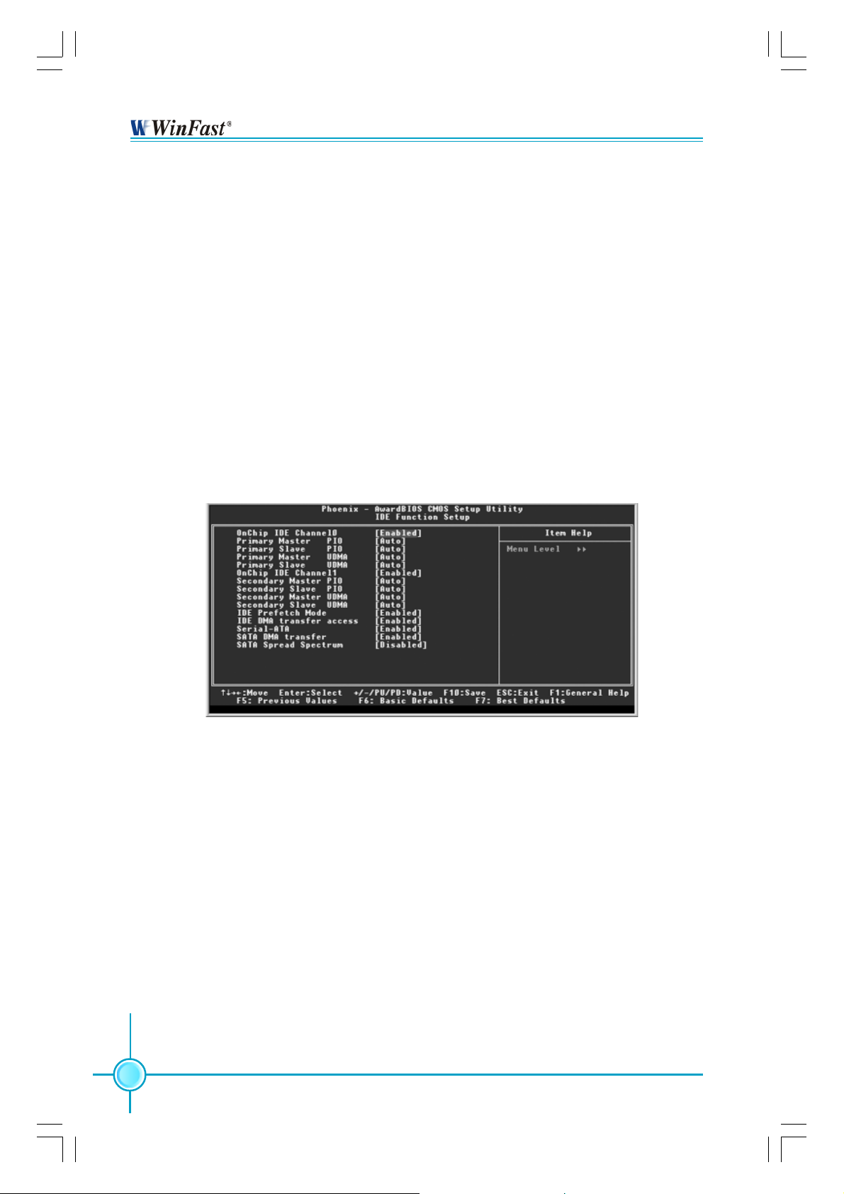
IDE Function Setup (Default: Press Enter)
Press <Enter> to set the items of IDE function setup. Please refer to page 34.
RAID Config (Default: Press Enter)
Press <Enter> to set the sub-items of RAID Configuration. Please refer to
page 35.
Init Display First (Default: PCI Slot)
This item is used to set which display device will be used first when your PC
starts up. The available setting values are: PCI Slot and Onboard/AGP.
OnChip USB (Default: V1.1+V2.0)
This setting allows you to enable or disable the onboard USB controller.
Selecting “V1.1+V2.0” enables the system to support both USB 1.1 and 2.0
specification. The setting options include Disabled, V1.1+V2.0 and V1.1.
USB KB/Storage Support (Default: Disabled)
Select “Enabled” if you need to use a USB-interfaced keyboard or storage
device in the operating system. The setting options include Enabled and
Disabled.
AC97 Audio (Default: Auto)
This option is used to set whether onboard AC97 Audio is enabled.
MAC Lan (nVIDIA) (Default: Disabled)
Setting to “Auto” allows the BIOS to auto-detect the nVIDIA LAN controller
and enable it. The setting options include Auto and Disabled.
32
IGPSK7MA-manual-V1.0-11-13-04.p65 2004-11-15, 17:3632
Page 40

Chapter 3 BIOS Description
MAC Media Interface (Default: MII)
When set as “Auto”, it allows the BIOS to auto-detect the nVIDIA LAN controller and enable it. The setting options are Auto and Disabled.
Machine MAC(NV) Address (Default: Disabled)
This option
MAC(NV) Address Input
When Machine MAC(NV) Address is setting to “Enabled”, you can select the
option and key in MAC address.
IDE HDD Block Mode (Default: Enabled)
This option is used to set whether the IDE HDD Block Mode is allowed. The
available setting values are Disabled and Enabled.
POWER ON Function (Default: BUTTON ONLY)
This option is used to set the power on method for your PC. Setting values
include: Password, Hot KEY, Mouse Move, Mouse Click, Any KEY, BUTTON
ONLY and Keyboard 98.
KB Power ON Password (Default: Enter)
When the POWER ON Function is set to Password, use this item to set the
password.
Hot Key Power ON (Default: Ctrl-F1)
When the POWER ON Function is set to Hot KEY, use this item to set the hot
key combination that turns on the system. The available setting values are:
Ctrl-F1-F12.
Onboard Serial Port 1/2 (Default: 3F8/IRQ4/2F8/IRQ3)
This option is used to assign the I/O address and interrupt request (IRQ)
for the onboard serial port 1/2.
Note: Do not try to set the same values for serial port 1 and 2.
UART Mode Select (Default: Normal)
Use this option to select the UART mode. The setting values include Normal,
IrDA, ASKIR and SCR. The setting value is determined by the infrared module
installed on the board.
UR2 Duplex Mode (Default: Half)
This option is available when UART 2 mode is set to either ASKIR or IRDA. This
option enables you to determine the infrared (IR) function of the onboard infrared chip. The available setting values are: Half and Full.
IGPSK7MA-manual-V1.0-11-13-04.p65 2004-11-15, 17:3633
33
Page 41
Chapter 3 BIOS Description
Onboard Parallel Port (Default: 378/IRQ7)
This option is used to assign the I/O address and interrupt request (IRQ) for
onboard parallel port controller. The setting values include: Disabled, 378/
IRQ7, 278/IRQ5 and 3BC/IRQ7.
Parallel Port Mode (Default: SPP)
Select an address and corresponding interrupt for the onboard parallel port.
The setting values include SPP, EPP, ECP, ECP+EPP.
PWRON After PWR-Fail (Default: Off)
This option is used to set what action the PC will take with the power supply
when it resumes after a sudden power failure. The available options are Off
(remain in turn off status), On (power on) and Former-Sts (resume with the
previous status).
IDE Function Setup Menu
Primary/Secondary Master/Slave PIO (Default: Auto)
The four IDE PIO (Programmed Input/Output) fields let you set a PIO mode
(0-4) for each of the four IDE devices that the onboard IDE interface supports.
Modes 0 through 4 provide successively increased performance. Choose
“Auto” to let the system auto detect which PIO mode is best, or select a PIO
mode from 0-4.
Primary/Secondary Master/Slave UDMA (Default: Auto)
UItraDMA technology provides faster access to IDE devices. If you install a
device that supports UItraDMA, change the appropriate items on this list to
Auto. The available setting values are: Disabled and Auto.
Serial-ATA (Default: Enabled)
This option is used to disable or enable the serial ATA function.
34
IGPSK7MA-manual-V1.0-11-13-04.p65 2004-11-15, 17:3634
Page 42

Chapter 3 BIOS Description
RAID Config Menu
IDE RAID (Default: Disabled)
This option is used to disable or enable the RAID function. When enabled,
the following grayed items will be activated.
IDE Channel 0/1 Master/Slave RAID (Default: Disabled)
This feature allows users to enable or disable the RAID function for each
IDE hard disk drive. The setting values are Enabled and Disabled.
SATA Primary/Secondary Master RAID (Default: Disabled)
This feature allows users to enable or disable the RAID function for each
SATA hard disk drive. The setting values are Enabled and Disabled.
IGPSK7MA-manual-V1.0-11-13-04.p65 2004-11-15, 17:3635
35
Page 43

Chapter 3 BIOS Description
Power Management Setup
Power Management Setup Menu
ACPI Suspend Type (Default: S1&S3)
This option is used to set the energy saving mode of the ACPI function.
When you select “S1 (POS)” mode, the power will not shut off and the power
supply status will remain as it is. In S1 mode the computer can be resumed
at any time. When you select “S3 (STR)” mode, the power will be cut off after
a delay period. The status of the computer before it enters STR will be saved in
memory, and the computer can quickly return to previous status when the STR
function wakes. When you select “S1 & S3” mode, the system will automatically
select the delay time.
Soft-Off by PBTN (Default: Instant-Off)
This option is used to set the power down method. This function is only valid
for systems using an ATX power supply. When “Instant-Off” is selected, press
the power switch to immediately turn off power. When “Delay 4 Sec” is
selected, press and hold the power button for four seconds to turn off power.
S5 Resume by USB (Default: Disabled)
This option is used to set whether the system is resumed by USB equipment
when it is in S5 (Soft-off) mode.
Power-On by Alarm (Default: Disabled )
This option is used to start up your PC by alarm. When this option is enabled,
the following two items are activated and user can set the desired alarm date
and time. The setting values are Disabled and Enabled.
36
IGPSK7MA-manual-V1.0-11-13-04.p65 2004-11-15, 17:3636
Page 44

Chapter 3 BIOS Description
Date of Month Alarm
This option is used to set the timing for the start-up date. The setting values
contain 0-31.
Time (hh:mm:ss) Alarm
This option is used to set the timing for the start-up time. The setting values
contain hh:0 – 23; mm:0 – 59; ss:0 – 59.
PnP/PCI Configurations
PnP/PCI Configurations Menu
Resources Controlled By (Default: Auto (ESCD))
This option is used to define the system resource control scheme. If all cards
you use support PnP, then select Auto (ESCD) and the BIOS will automatically
distribute interruption resources. If the ISA cards you installed do not support
PnP, you will need to select “Manual” and manually adjust interruption resources in the event of hardware conflicts. However, since this motherboard
has no ISA slot, this option does not apply.
PCI/VGA Palette Snoop (Default: Disabled)
If you use a nonstandard VGA card, use this option to solve graphic acceleration card or MPEG audio card problems (e.g., colors not accurately displayed).
The setting values are Disabled and Enabled.
37
IGPSK7MA-manual-V1.0-11-13-04.p65 2004-11-15, 17:3637
Page 45

Chapter 3 BIOS Description
PC Health Status (O.T.S)
PC Health Status (O.T.S) menu
Shutdown Temperature (Default: Disabled)
This option is used to set the system temperature upper limit. When the
temperature exceeds the setting value, the motherboard will automatically cut
off power to the computer. The setting values are Disabled and 60
0
65
C/1490F, 700C/1580F.
0
C/1400F,
X-BIOS I I (Over Clocking)
X-BIOS I I
Memory Vmem Select (Default: Default )
This option is used to set the memory voltage value.
38
(Over Clocking) Menu
IGPSK7MA-manual-V1.0-11-13-04.p65 2004-11-15, 17:3638
Page 46

Chapter 3 BIOS Description
Load Basic Defaults
Press <Enter> to select this option. A dialogue box will pop up that allows you to
load the default BIOS settings. Select <Y> and then press <Enter> to load the
defaults. Select <N> and press <Enter> to exit without loading. The defaults set
by BIOS set the basic system functions in order to ensure system stability. But if
your computer cannot POST properly, you should load the basic defaults to
restore the default settings, then carry out failure testing. If you only intend to
load the defaults for a specific option, you can select the desired option and
press the <F6> key.
Load Best Defaults
Select this option and press <Enter>, and a dialogue box will pop up to let you
load the best BIOS default settings. Select <Y> and then press <Enter> to load
the best defaults. Select <N> and press <Enter> to exit without loading. The
defaults set by BIOS are the best performance parameters for the system, to
improve the performance of your system components. However, if the best
performance parameters are not supported by your hardware devices, it will
likely cause system reliability and stability issues. If you only want to load the
best default for a specific option, select the desired option and press the <F7>
key.
Set Supervisor/User Password
The access rights and permissions associated with the Supervisor password are
higher than those of a regular User password. The Supervisor password can be
used to start the system or modify the CMOS settings. The User password can
also start the system. While the User password can be used to view the current
CMOS settings, these settings cannot be modified using the User password.
When you select the Set Supervisor/User Password option, the following message
will appear in the center of the screen, which will help you to set the password:
Enter Password:
Enter your password, not exceeding 8 characters, then press <Enter>. The
password you entered will replace any previous password. When prompted,
key in the new password and press <Enter>.
39
IGPSK7MA-manual-V1.0-11-13-04.p65 2004-11-15, 17:3639
Page 47

Chapter 3 BIOS Description
If you do not want to set a password, just press <Enter> when prompted to enter
a password, and the following message will appear on the screen. If no password is keyed in, any user can enter the system and view/modify the CMOS
settings.
PASSWORD DISABLED!!!
Press any key to continue …
Under the menu “Advanced BIOS Features Setup”, if you select “System” from
the Security Option, you will be prompted to enter a password once the system
is started or whenever you want to enter the CMOS setting program. If the incorrect password is typed, you will not be permitted to continue.
Under the menu “Advanced BIOS Features Setup”, if you select “Setup” from the
Security Option, you will be prompted to enter a password only when you enter
the CMOS setting program.
Save & Exit Setup
When you select this option and press <Enter>, the following message will
appear in the center of the screen:
SA VE to CMOS and EXIT (Y/N) ? Y
Press <Y> to save your changes in CMOS and exit the program; press <N> or
<ESC> to return to the main menu.
Exit Without Saving
If you select this option and press <Enter>, the following message will appear
in the center of the screen:
Quit Without Saving (Y/N) ? N
Press <Y> to exit CMOS without saving your changes; press <N> or <ESC> to
return to the main menu screen.
40
IGPSK7MA-manual-V1.0-11-13-04.p65 2004-11-15, 17:3640
Page 48

Chapter
4
4
The utility CD that came with the motherboard contains
useful software and several utility drivers that enhance the
motherboard features.
This chapter includes the following information:
Utility CD content
Start to install drivers
IGPSK7MA-manual-V1.0-11-13-04.p65 2004-11-15, 17:3641
Page 49

Chapter 4 Driver CD Introduction
Utility CD Content
This motherboard comes with one Utility CD. To begin using the CD, simply insert
the CD into your CD-ROM drive. The CD will automatically display the main menu
screen.
1. Install Driver
Using this choice, you can install all the drivers for your motherboard. You should
install the drivers in order, and you need to restart your computer after the drivers
are all installed.
A. nVIDIA nForce Chipset System B.DirectX 9.0b
C.USB2.0 Driver D. Audio Driver
2. Accessories
Use this option to install additional software programs.
A. SuperUtility (optional)
a. SuperStep
SuperStep is a powerful and easy-to-operate tool for over clocking. You ca n
quickly increase your CPU’s working frequency through its user-friendly
interface. It will enhance your CPU’s performance and meet all kinds of
DIY requirements
b.SuperLogo
SuperLogo can display user-designed graphics and pictures, such as a
company logo or personal photos, thus making your PC more personalized and friendly.
c.SuperUpdate
SuperUpdate function can help to update the BIOS through Internet
directly.
42
IGPSK7MA-manual-V1.0-11-13-04.p65 2004-11-15, 17:3642
Page 50

Chapter 4 Driver CD Introduction
B. Adobe Reader
C. Norton Internet Security
4. Browse CD
Click here to browse CD content.
4. HomePage
Click here to visit Foxconn motherboard homepage.
Start to install drivers
Click <Install Driver> to enter the driver installation menu (as shown in Figure
1). Click the relevant buttons to install nVIDIA nForce Chipset System, DirectX
9.0b, USB2.0 Driver and Audio Driver from this CD.
Follow the screen
order to install
the motherboard
drivers
1
IGPSK7MA-manual-V1.0-11-13-04.p65 2004-11-15, 17:3643
43
Page 51

Chapter 5 nVIDIA RAID Introduction
NVIDIA RAID
RAID Arrays
This section describes the following types of RAID arrays that NVIDIA RAID
supports:
• RAID 0
RAID 0 defines a disk striping scheme that improves the disk read and write
times for many applications.
• RAID 1
RAID 1 defines techniques for mirroring data.
• RAID 0+1
RAID 0+1 combines the techniques used in RAID 0 and RAID 1 arrays.
• Spanning (JBOD)
JBOD provides a method for combining drives of different sizes into one large
disk.
Summary of RAID Configurations
Array
RAID 0
RAID 1
RAID
0+1
JBOD
Advantages
High data throughput.
100% data
redundancy.
Optimized for both 100%
data redundancy and
performance. Allows
spare disks.
Combines and uses the
capacity of odd size
drives.
Drawbacks
No fault tolerance.
Requires two drives
for the storage space
of one drive.
Requires two drives for
the storage space of
one drive—the same
as RAID level 1.
Decreases performance because of the
difficulty in using drives
concurrently or to optimize drives for different uses.
# Hard Disks
multiple
2
4+
multiple
Fault T olerance
None
Yes
Yes
No
44
IGPSK7MA-manual-V1.0-11-13-04.p65 2004-11-15, 17:3644
Page 52

Chapter 5 nVIDIA RAID Introduction
Basic Configuration Instructions
The following are the basic steps for configuring NVIDIA RAID:
Non-Bootable RAID Array
1. Choose the hard disks that are to be RAID enabled in the system BIOS.
2. Specify the RAID level, either Mirroring (RAID 1), Striping (RAID 0), Stripe
Mirroring (RAID 0+1), or Spanning (JBOD) and create the desired RAID array.
3. Install the operating system on one hard disk, then reboot the computer.
4. Run the Windows nForce Setup application and install the RAID driver.
5. Initialize the NVRAID Array.
Bootable RAID Array
1. Choose the hard disks that are to be RAID enabled in the system BIOS.
2. Specify the RAID level, either Mirroring (RAID 1), Striping (RAID 0), Stripe
Mirroring (RAID 0+1), or Spanning (JBOD) and create the desired RAID array.
3. Boot from the Windows CD, then press F6 when the Windows Setup appears.
4. Insert the RAID driver floppy to install the nForce RAID driver.
5. Initialize the NVRAID Array.
IGPSK7MA-manual-V1.0-11-13-04.p65 2004-11-15, 17:3645
45
Page 53

Chapter 5 nVIDIA RAID Introduction
Setting Up the BIOS
1. Start up the computer, then press <Delete> to enter the BIOS setup. Use the
arrow keys to select Integrated Peripherals, then press <Enter>.
2. Use the arrow keys to highlight the RAID Config, then press <Enter>.
3. From the RAID Config window, enable the IDE RAID, the other items would be
activated, then you can enable the disks that you want to use as RAID disks.
Note: Make sure to enable the SATA drives if you are setting up a RAID 0+1
array.
4. Press <F10> to save the configuration and exit.
46
IGPSK7MA-manual-V1.0-11-13-04.p65 2004-11-15, 17:3646
Page 54

Chapter 5 nVIDIA RAID Introduction
Entering the RAID BIOS Setup
1. After rebooting your PC, wait until you see the RAID software prompting you to
press <F10>. The RAID prompt appears as part of the system POST and boot
process prior to loading OS.
2. Press <F10>, and the NVIDIA RAID Utility --- Define a New Array window will
appear.
By default, RAID Mode is set to Mirroring and Striping Block is set to Optimal.
Understanding the “Define a New Array” Window
Use the Define a New Array window to
• Select the RAID Mode
• Set up the Striping Block
• Specify which disks to use for the RAID Array
Depending on the platform used, the system can have one or more channels. In
a typical system there is usually one controller and multiple channels, and each
channel has a slave and a master.
The channel/controller/master/slave status of each hard disk is given in the Loc
(location) columns of the Free Disks and Array Disks lists.
1.0.M
M: Master
S: Slave
0: Controller
Channel - Typically, channel 0 is used for
Parallel A T A drivers while channel 1 is used
for Serial ATA drives.
47
IGPSK7MA-manual-V1.0-11-13-04.p65 2004-11-15, 17:3647
Page 55

Chapter 5 nVIDIA RAID Introduction
In the example above, 1.0.M means the hard drive is attached to Channel 1,
Controller 0, and the drive is set to Master. The following is a list of all possible
combinations:
Parallel A T A
0.0.M Channel 0, controller 0, Master
0.0.S Channel 0, controller 0, Slave
0.1.M Channel 0, controller 1, Master
0.1.S Channel 0, controller 1, Slave
Serial A T A
1.0.M Channel 1, controller 0, Master
1.1.M Channel 1, controller 1, Slave
Note: There is no such thing as Slave drive in Serial ATA. All drives are considered to be Master since there is a one to one connection between the drive and
the controller.
Using the Define a New Array Window
If necessary, press the <Tab> key to move from field to field until the appropriate
field is highlighted.
• Selecting the RAID Mode
By default, this is set to [Mirroring]. To change to a different RAID mode, press
the down arrow key until the mode that you want appears in the RAID Mode
box—either [Mirroring], [Striping], [Spanning], or [Stripe Mirroring].
• Selecting the Striping Block Size
Striping Block size is given in kilobytes, and affects how data is arranged on the
disk. It is recommended to leave this value at the default [Optimal], which is
32KB, but the values can be between [4 KB] and [128 KB].
• Assigning the Disks
The disks that you enabled from the RAID Config BIOS setup page appear in the
Free Disks block. These are the drives that are available for use as RAID array
disks.
48
IGPSK7MA-manual-V1.0-11-13-04.p65 2004-11-15, 17:3648
Page 56

Chapter 5 nVIDIA RAID Introduction
To designate a free disk to be used as a RAID array disk,
1. Tab to the Free Disks section. The first disk in the list is selected.
2. Move it from the Free Disks block to the Array Disks block by pressing the right
arrow key (
). The first disk in the list is moved, and the next disk in the list is
selected and ready to be moved.
3. Continue pressing the right-arrow key (
) until all the disks that you want to
use as RAID array disks appear in the Array Disks block.
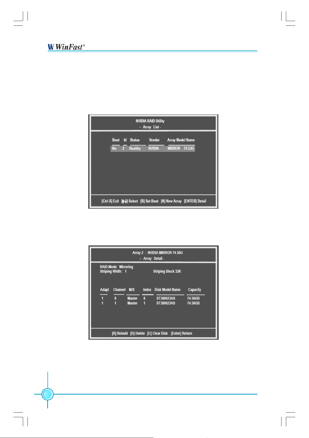
It shows that two disks have been assigned as RAID1 array disks in the figure
above.
Completing the RAID BIOS Setup
1. After assigning your RAID array disks, press <F7>. The Clear disk data prompt
appears.
IGPSK7MA-manual-V1.0-11-13-04.p65 2004-11-15, 17:3649
49
Page 57
Chapter 5 nVIDIA RAID Introduction
2. Press <Y> if you want to wipe out all the data from the RAID array, otherwise
press <N>. You must choose Yes if the drives were previously used as RAID
drives.
The Array List window appears, where you can review the RAID arrays that you
have set up.
3. Use the arrow keys to select the array that you want to set up, then press
<Enter>. The Array Detail window appears.
4. If you want to mark this disk as empty and wipe out all its contents then press
<C>.
5. At the prompt, press <Y> to wipe out all the data, otherwise press <N>.
6. Press <Enter> again to go back to the previous window and then press <F10>
to exit the RAID setup.
50
IGPSK7MA-manual-V1.0-11-13-04.p65 2004-11-15, 17:3750
Page 58

Chapter 5 nVIDIA RAID Introduction
NVIDIA RAID Utility Installation
Installing the NVIDIA RAID Software Under Windows (for Non-bootable RAID
Array)
This section describes how to run the setup application and install the RAID
software which will upgrade the Windows IDE driver and install the RAID driver.
1. Start the nForce Setup program to open the NVIDIA Windows nForce Drivers
page.
2. Select the modules that you want to install. Select the relative options that you
have configured.
3. Click Next and then follow the on-screen instructions.
4. After the installation is completed, be sure to reboot the PC.
5. After the reboot, initialize the newly created array.
51
IGPSK7MA-manual-V1.0-11-13-04.p65 2004-11-15, 17:3751
Page 59

Chapter 5 nVIDIA RAID Introduction
Installing the RAID Driver (for bootable RAID Array)
1. After you complete the RAID BIOS setup, boot from the Windows CD, and the
Windows Setup program starts.
2. Press <F6> and wait for the Windows Setup screen to appear.
3. Specify the NVIDIA drivers:
(1) Insert the floppy that has the RAID driver, press <S>, then press <Enter>. The
Windows Setup screen appears as below:
(2) Select “NVIDIA RAID CLASS DRIVER” and then press <Enter>.
(3) Press <S> again at the Specify Devices screen, then press <Enter>.
(4) Select “NVIDIA nForce Storage Controller” and then press <Enter>. The
following Windows Setup screen appears listing both drivers:
52
IGPSK7MA-manual-V1.0-11-13-04.p65 2004-11-15, 17:3752
Page 60

Chapter 5 nVIDIA RAID Introduction
4. Press <Enter> to continue with operating system installation. Be sure that
copying files from the floppy is completed, then take out the floppy.
5. Follow the instructions on how to install operating system. During the GUI
portion of the install you might be prompted to click Yes to install the RAID driver.
Click Yes as many times as needed in order to finish the installation. This will
not be an issue with a signed driver.
Note: Each time you add a new hard drive to a RAID array, the RAID driver will
have to be installed under Windows once for that hard drive. After that, the driver
will not have to be installed.
53
IGPSK7MA-manual-V1.0-11-13-04.p65 2004-11-15, 17:3753
Page 61

Chapter 5 nVIDIA RAID Introduction
Initializing and Using the Disk Array
The RAID array is now ready to be initialized under Windows.
1. Launch Computer Management by clicking “Start” —> “Settings” —> “Control
Panel”, then open the “Administrative Tools” folder and double click on “Computer Management”.
2. Follow on-screen instructions to install. While finished, the “Computer Management” window appears.
The actual disks listed will depend on your system, and the unallocated partition is the total combined storage of two hard disks. You must format the
unallocated disk space in order to use it.
7. Format the unallocated disk space. Right click “Unallocated space”, select
“New Partition…” and follow the wizard. After the drive has been formatted, it is
ready for use.
54
IGPSK7MA-manual-V1.0-11-13-04.p65 2004-11-15, 17:3754
Page 62

Chapter 5 nVIDIA RAID Introduction
Win2K Limitation with Bootable RAID
In Windows 2000 (Service Pack 2 or previous versions), the end user cannot
install this operating system to a bootable RAID volume.
Solution
There are two solutions to resolve this issue.
I) Use the NVRAID Tool (nForce Driver Version 5.xx) to convert the
boot volume to a RAID array. Here are the detailed step by step
instructions:
1. Install Windows 2000 on a selected hard drive.
2. Download and install Windows 2000 Service Pack 4 from Microsoft’s
website.
3. Reboot the system. Press the <DEL> key as the system is rebooting to
enter into the system BIOS.
4. Select Integrated Peripherals
5. Enable RAID for the selected drive (the one containing the Windows 2000
operating system). Then press <F10> to exit and save settings in the system
BIOS. This action reboots the system.
6. Press <F10> as the system is rebooting to go into the RAID ROM. The
system directs you into the NVIDIA RAID Utility.
7. Select Striping under RAID Mode. Press <Tab> to go into the Free Disk
menu, then use the Right Arrow key to add the desired disk.
8. Press <F7> to finish. Select <N> (NO) when asked to Clear Disk Data.
9. Press Ctrl-X to exit. The system reboots into Windows 2000.
10. Install the NVIDIA nForce Driver Package while in Windows 2000. Then
reboot the system.
11. Go to START>Programs>Nvidia Corporation and select NVRAID Manager.
You should see the single disk RAID array (in striping mode) that was created
from the boot disk.
12. Select the single boot disk RAID Array by clicking on it.
RAID Config.
IGPSK7MA-manual-V1.0-11-13-04.p65 2004-11-15, 17:3755
55
Page 63

Chapter 5 nVIDIA RAID Introduction
13. Select Convert Array under the System Tasks. The Convert Array wizard
is displayed. Then select Next.
14. Select the desired type of RAID array you want to convert. Then select
Next.
15. You are prompted to select the desired Free Disk(s) to add to the
bootable RAID array.
16. Click Finish.
At this point, NVRAID starts converting the single disk RAID array into a multidisk RAID array in a bootable format.
Note: Conversion may take 1-2 hours depending on disk size.
II) The user must create a combination installation CD that includes
Windows 2000 and SP3 or SP4 fixes integrated in. To create the
combination installation CD, refer to the following website:
http://www.microsoft.com/windows2000/downloads/servicepacks/sp4/
HFdeploy.htm
Note:
4, RAID is still supported on Windows 2000. However, the end user will not
be able to create a bootable RAID volume.
If the end user chooses not to install Windows 2000 Service Pack 3 or
56
IGPSK7MA-manual-V1.0-11-13-04.p65 2004-11-15, 17:3756
 Loading...