

Page 1

Statement:
This manual is the intellectual property of Foxconn, Inc. Although the
information in this manual may be changed or modified at any time,
Foxconn does not obligate itself to inform the user of these changes.
Trademark:
All trademarks are the property of their respective owners.
Version:
User’s Manual V1.1b for C51XEM2AA motherboard.
P/N: 91-181C51M51E-00-G
Symbol description:
Note: refers to important information that can help you to use motherboard
better.
Attention: indicates that it may damage hardware or cause data loss,
and tells you how to avoid such problems.
Warning: means that a potential risk of property damage or physical
injury exists.
More information:
If you want more information about our products, please visit Foxconn’s
website: http://www.foxconnchannel.com
This product and its accessories are produced after 13th Aug., 2005 and
comply with the WEEE2002/96EC directive.
Page 2

Declaration of conformity
HON HAI PRECISION INDUSTRY COMPANY LTD
66 , CHUNG SHAN RD., TU-CHENG INDUSTRIAL DISTRICT,
TAIPEI HSIEN, TAIWAN, R.O.C.
declares that the product
Motherboard
C51XEM2AA
is in conformity with
(reference to the specification under which conformity is declared in
accordance with 89/336 EEC-EMC Directive)
þ EN 55022: 1998/A2: 2003Limits and methods of measurements of radio disturbance
characteristics of information technology equipment
þ EN 61000-3-2/:2000 Electromagnetic compatibility (EMC)
Part 3: Limits
Section 2: Limits for harmonic current emissions
(equipment input current <= 16A per phase)
þ EN 61000-3-3/A1:2001 Electromagnetic compatibility (EMC)
Part 3: Limits
Section 2: Limits of voltage fluctuations and flicker in low-voltage
supply systems for equipment with rated current <= 16A
þ EN 55024/A2:2003 Information technology equipment-Immunity characteristics limits
and methods of measurement
Signature : Place / Date : TAIPEI/2006
Printed Name : James Liang Position/ Title : Assistant President
Page 3

Declaration of conformity
Trade Name: Foxconn
Model Name: C51XEM2AA
Responsible Party: PCE Industry Inc.
Address: 458 E. Lambert Rd.
Fullerton, CA 92835
Telephone: 714-738-8868
Facsimile: 714-738-8838
Equipment Classification: FCC Class B Subassembly
Type of Product: Motherboard
Manufacturer: HON HAI PRECISION INDUSTRY
COMPANY LTD
Address: 66 , CHUNG SHAN RD., TU-CHENG
INDUSTRIAL DISTRICT, TAIPEI HSIEN,
TAIWAN, R.O.C.
Supplementary Information:
This device complies with Part 15 of the FCC Rules. Operation is subject to the follow-
ing two conditions : (1) this device may not cause harmful interference, and (2) this
device must accept any interference received, including interference that may cause
undesired operation.
Tested to comply with FCC standards.
Signature : Date : 2006
Page 4

Table of Contents
1
Chapter
Main Features.............................................................................................2
Highlight Features.......................................................................................4
Layout........................................................................................................7
Rear Panel Ports.........................................................................................8
1
Product Introduction
Chapter
CPU..........................................................................................................11
Memory....................................................................................................14
Power Supply...........................................................................................16
Other Connectors.....................................................................................17
Expansion Slots........................................................................................21
Jumpers...................................................................................................22
Chapter
Enter BIOS Setup......................................................................................24
Main menu................................................................................................24
Standard CMOS Features.........................................................................27
Advanced BIOS Features.........................................................................29
Advanced Chipset Features.....................................................................31
Integrated Peripherals...............................................................................38
Power Management Setup........................................................................39
PnP/PCI Configurations.............................................................................41
System Monitor.........................................................................................42
Load Defaults...........................................................................................44
Set Password..........................................................................................44
Set User Name.........................................................................................44
Save & Exit Setup.....................................................................................44
Exit Without Saving...................................................................................45
2
2
3
3
Installation Instructions
BIOS Description
Page 5

Table of Contents
Chapter
Utility CD content......................................................................................47
Installing drivers.......................................................................................48
Installing Utilities.......................................................................................48
NVIDIA nTune 4.0.....................................................................................50
Fox LiveUpdate........................................................................................60
Media Shield RAID Manager......................................................................67
Network Access Manager........................................................................75
NVIDIA SLI
NVIDIA RAID............................................................................................85
Audio Configuration..................................................................................97
On board LED Code Table.......................................................................101
4
4
5
5Chapter
6
6Chapter
TM
Technology..........................................................................82
Driver CD Introduction
Directions for Bundled Software
Appendix
Page 6

Attention:
1.Attach the CPU and heatsink using silica gel to ensure full contact.
2.It is suggested to select high-quality, certified fans in order to avoid
damage to the motherboard and CPU due high temperatures.
3.Never turn on the machine if the CPU fan is not properly installed.
4.Ensure that the DC power supply is turned off before inserting or
removing expansion cards or other peripherals, especially when
you insert or remove a memory module. Failure to switch off the DC
power supply may result in serious damage to your system or
memory module.
Attention:
We cannot guarantee that your system will operate normally while
over-clocked. Normal operation depends on the over-clock capacity
of your device.
Attention:
Since BIOS programs are upgraded from time to time, the BIOS
description in this manual is just for reference. We do not guarantee
that the content of this manual will remain consistent with the actual
BIOS version at any given time in the future.
Attention:
The pictures of objects used in this manual are just for your reference.
Please refer to the physical motherboard.
Page 7

This manual is suitable for motherboard of C51XEM2AA. Each
motherboard is carefully designed for the PC user who wants
diverse features.
-L with onboard 10/100M LAN (Default is omitted.)
-K with onboard Gigabit LAN
-6 with 6-Channel audio (Default is omitted.)
-8 with 8-Channel audio
-E with 1394 function
-S with SATA function
-2 with DDR2 function
-Rwith RAID function
You can find PPID label on the motherboard. It indicates the
functions that the motherboard has.
For example:
On the black mark of the PPID label, it means the mother-
board supports 6-Channel Audio (-6), 1394 port (-E), onboard
10/100M LAN (-L), SATA function (-S).
Page 8

Chapter
Thank you for buying Foxconn’s C51XEM2AA series
motherboard. This series of motherboard is one of our new
products, offers superior performance, and uses the advanced
NVIDIA nForce® 590 SLI MCP.
This chapter includes the following information:
1
1
v Main Features
v Highlight Features
v Layout
v Rear I/O Ports
Page 9

Chapter 1 Product Introduction
Main Features
Size
· ATX form factor of 12 inch x 9.6 inch
Microprocessor
· Supports AMD® Socket AM2 Athlon
64 and SempronTM processor
· Supports HyperTransport up to 2000MT/s
MCP
· NVIDIA nForce® 590 SLI MCP
System Memory
· Four 240-pin DIMM slots
· Supports Dual-Channel DDR2 533/667/800
· Supports up to 8GB DDR2 memory
USB 2.0 Ports
TM
64 X2 Dual-Core, Athlon
TM
64 FX, Athlon
· Supports hot plug
·Ten USB 2.0 ports (six rear panel ports, two onboard USB headers
providing four extra ports)
· Supports wake-up from S1 and S3 mode
·Supports USB 2.0 protocol up to 480Mbps transmission rate
TM
Onboard Serial ATA II
· 300MBps data transfer rate
· Six Serial ATA II connectors
· NVIDIA MediaShieldTM RAID with support for RAID 0, RAID 1, RAID 0+1,
RAID 5, and JBOD
· Supports hot plug and NCQ (Native Command Queuing )
Dual Onboard LAN (-K)
· Two LAN interface built-in onboard
· Supports 10/100/1000 Mbit/sec Ethernet
2
Page 10

Chapter 1 Product Introduction
Onboard 1394 (-E ) (optional)
· Support hot plug
·Two 1394a port with rate of transmission at 400 Mbps
· One 1394b port with rate of transmission at 800 Mbps
Onboard Audio (-8)
· Supports 8-channel audio
· Supports S/PDIF output
· Supports Jack-Sensing function
Dual PCI Express x16 Support
· Supports 4 GB/sec (8 GB/sec concurrent) bandwidth
· Low power consumption and power management features
Green Function
· Supports ACPI (Advanced Configuration and Power Interface)
· Supports S0 (normal), S1 (power on suspend), S3 (suspend to RAM), S4
(Suspend to disk - depends on OS), and S5 (soft - off)
· Supports AMD® Cool ‘n’ QuietTM technology
Expansion Slots
· Two PCI slots
· One PCI Express x1 slot
· One PCI Express x4 slot
· Two PCI Express x16 Graphics slots
3
Page 11

Chapter 1 Product Introduction
Hightlight Features
Engineered for Enthusiasts
NVIDIA nForce® 590 SLITM media and communication processors (MCPs) deliver
the tools and performance enthusiasts demand. When combined with select NVIDIA
GeForce graphics cards and other system components, you get automatic access
to faster bus speeds. Ready for system overclocking and greater data throughput.
NVIDIA LinkBoostTM Technology
NVIDIA nForce 590 MCP automatically increases bandwidth when selected NVIDIA
GeForce® graphics cards are detected.
NVIDIA® SLITM-Ready components
Look for other components including memory modules that are optimized for use
with NVIDIA nForce 590 SLI MCP motherboards for maximum performance. These
components automatically run at faster bus speeds and are ready for overclocking.
Designed for NVIDIA® SLITM Technology
NVIDIA SLI Technology is a revolutionary platform innovation that allows users to
intelligently scale graphics performance by combining multiple NVIDIA graphics
solutions in a single system with an NVIDIA nForce SLI MCP.
2x16 PCI-E SLI Support
Two full-bandwidth, 16-lane PCI Express links ensure maximum graphics perfor-
mance for next-generation GPUs and games. Offers twice the PCI Express band-
width of X8 SLI solutions.
NVIDIA MediaShield Storage
Suite of features that safeguards your most important digital media assets; always
reliable, scalable, and accessible. Includes RAID and SATA drive support.
Multiple Disk Setup
Through a simple wizard-based interface, you can effortlessly set up your
drives for better data protection, faster disk access or maximum storage
capacity. MediaShield automatically selects RAID 0, 1, 0+1 or 5
configuration according to your needs. Advanced users can access RAID
options directly.
4
Page 12

Chapter 1 Product Introduction
DiskAlert System
The event of a disk failure, MediaShield users see an image that
highlights which disk has failed to make it easier to identify, replace, and
recover.
RAID Morphing
MediaShield allows users to change their current RAID set-up to another
configuration in a one-step process called morphing. This eliminates the
need to back up data and follow multiple steps in the process.
Bootable Multidisk Array
MediaShield storage fully supports the use of multi-disk array for loading
the operating system at power-up.
Six SATA 3Gb/s Drives
Combine up to 6 SATA drives into one volume for bigger, faster RAID.
More drives mean more configuration options such as 6 RAID 0 (striped)
drives for maximum throughput, or Dual RAID 5 arrays. Take advantage of
the latest SATA-2, 3Gb/s hard disk drives with full support for native and
tagged command queuing and hot plug. Native command queuing
provides higher disk performance in a multi-threaded environment by
performing out-of-order disk accesses.
Networking with NVIDIA nForce
NVIDIA networking delivers the highest network throughput at the lowest CPU
utiliization. The manageable and stable NVIDIA networking solution results in
better networking management and a lower total cost of ownership. Only
NVIDIA integrates this level of networking features to allow you to take your
online experience to the next level.
NVIDIA Native Gigabit Ethernet
The industry’s fastest Gigabit Ethernet performance eliminates network
bottlenecks and improves overall system efficiency and performance.
NVIDIA FirstPacket™ technology
Be the ‘King of Ping’ with NVIDIA FirstPacket technology. Get the crystal-
5
Page 13

Chapter 1 Product Introduction
clear phone conversations and online gaming performance you expect.
NVIDIA FirstPacket technology assures your game data, VoIP
conversations, and large file transfers are delivered according to
preferences set by you in an intuitive wizard.
NVIDIA DualNet® technology
Get Double-Barrel Gigabit Ethernet with two integrated networking
connections on your NVIDIA nForce 500 series MCP.
Dual Gigabit Ethernet with Teaming
Teaming allows the two connection to work together to provide up to
twice the Ethernet bandwidth for transferring large amounts of data
from home file servers to other PCs. It also provides network
redundancy through fail-over capability.
TCP/IP Acceleration
Delivers the highest system performance by offloading CPU-
intensive packet filtering tasks in hardware, providing users with a
PC networking environment that is faster.
NVIDIA nTune™ 4.0 Utility
Now with access to more settings from this Windows-based utility. NVIDIA
nTune performance manager allows automatic tuning for optimal
performance and the ability to customize. Once configured, nTune
automatically chooses the right system settings for the application that is
being run based on your saved profiles and personal rules.
High Definition Audio (HDA)
High definition audio brings consumer electronics quality sound to the PC
delivering high quality sound from multiple channels. Using HDA, systems
can deliver 192 kHz/32-bit quality for eight channels, supporting new audio
formats.
USB 2.0
A standard plug-and-play interface that provides easy-to-use connectivity for
USB devices.
6
Page 14
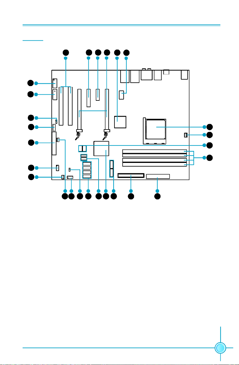
Layout
7
8
9
10
11
12
13
Chapter 1 Product Introduction
5
6
34
12
26
25
24
23
14
15 17
16
1. 8-pin ATX_12V Power Connector
2. C51XE
3. PCI Express x16 Slots
4. PCI Express x1 Slot
5. PCI Express x4 Slot
6. PCI Slots
7. IEEE1394a Connector
8. AUX PEX PWR Connector
9. Speaker Connector
10. Front Audio Connector
11. FDD Connector
12. COM1 Connector
13. SYS Fan Connector
18 19 20
21 22
14. MCP Fan Connector
15. Front Panel Connector
16. Clear CMOS Jumper
17. Serial ATA II Connectors
18. USB Connectors
19. MCP55P XE
20. Serial ATA II Connectors
21. ATA 133/100/66 IDE Connector
22. 24-pin ATX Power Connector
23. DDR2 DIMM Slots
24. Debug LED (optional)
25. CPU FAN Connector
26. Socket AM2
Note: The above motherboard layout is provided for reference only, please refer to the
physical motherboard.
7
Page 15
Chapter 1 Product Introduction
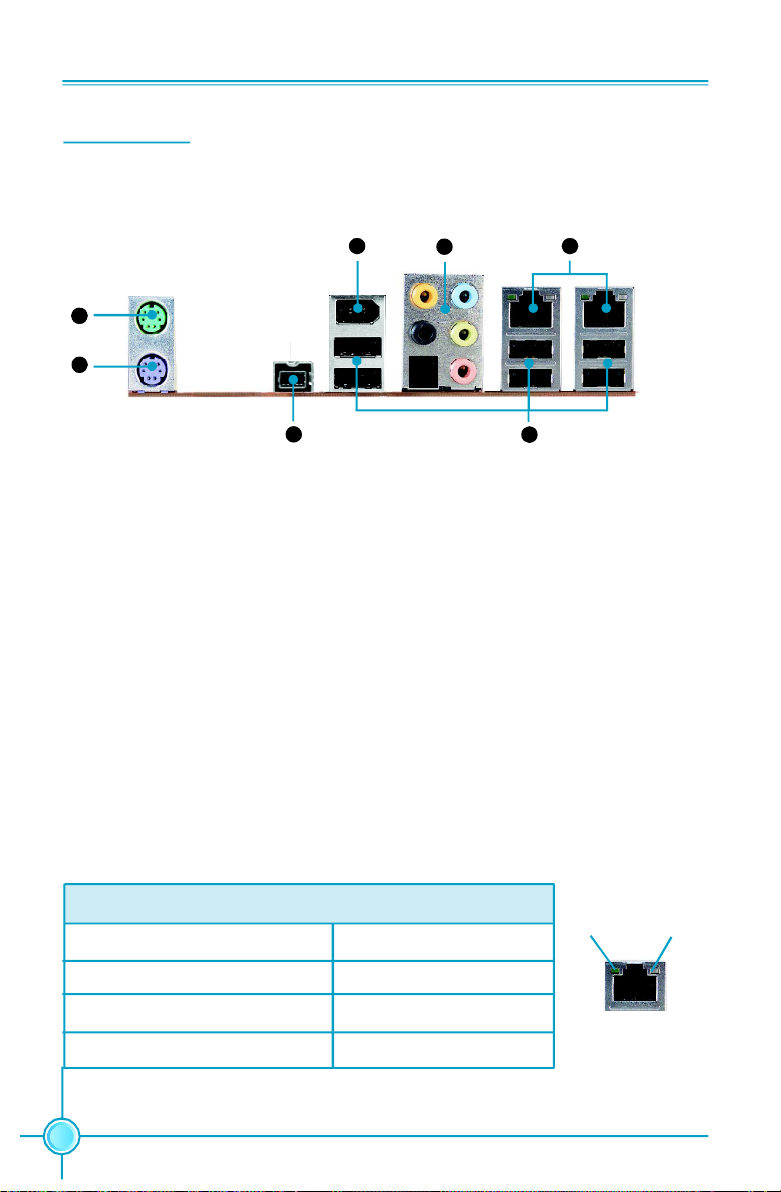
Rear I/O Ports
This motherboard provides the ports as below:
7 5
1
2
3
6
4
1. PS/2 Mouse Port
This port is used to connect a PS/2 mouse.
2. PS/2 Keyboard Port
This port is used to connect a PS/2 keyboard.
3. IEEE1394b Port
This port is used to connect a 1394b device.
4. USB2.0 Ports
The six ports are used to connect USB2.0 devices.
5. LAN Ports
The left LED is no function (always off). The right LED function sees below table.
Link/Active/Speed LED
Status Description
Yellow/Light Up/Blink 10Mbps/Link/Activity
Yellow and Green/Light Up/Blink 100Mbps/Link/Activity
Green/Light Up/Blink 1000Mbps/Link/Activity
8
Link/Active/
Speed LED
Off
Left
LAN Port
Right
Page 16
Chapter 1 Product Introduction
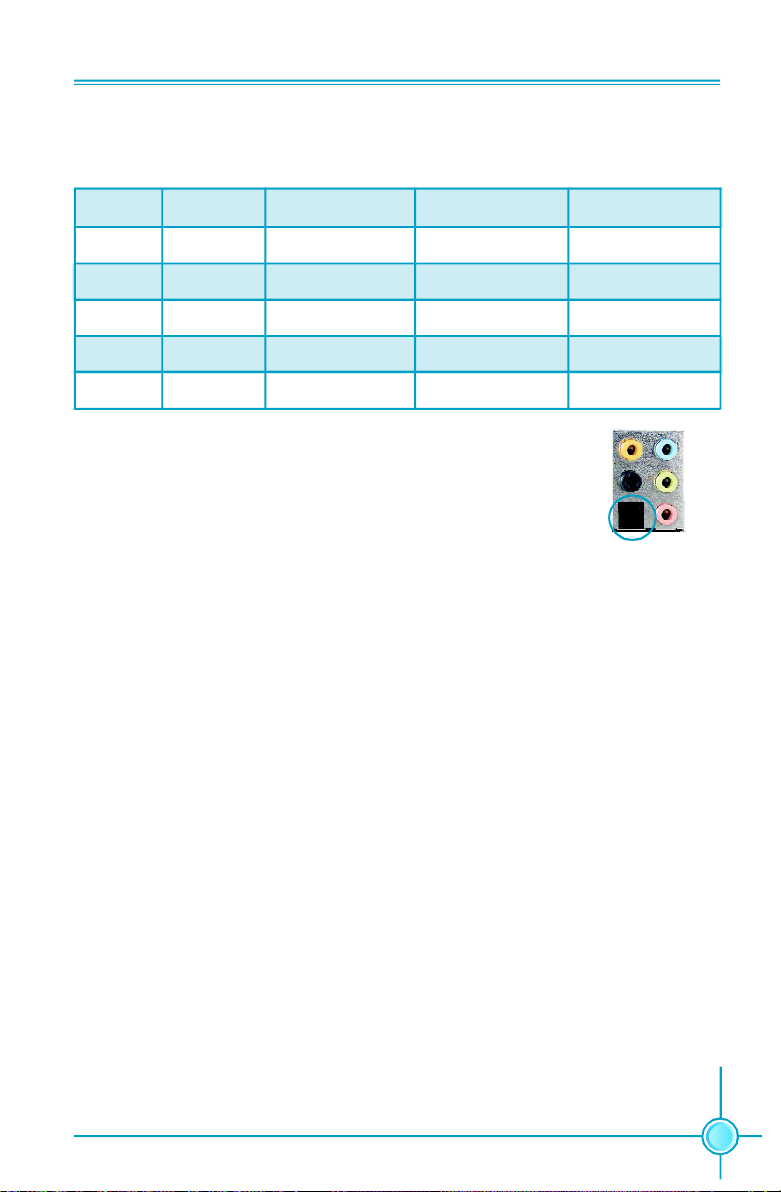
6. Line in, Line out, Microphone, Rear, LEF/CEN Jacks & Optical S/PDIF Out
Port
Port 2-channel 4-channel 6-channel 8-channel
Blue Line In Line In Line In Line In
Green Line Out Front Speaker Out Front Speaker Out Front Speaker Out
Pink Mic In Mic In Mic In Mic In
Orange - - Center/Subwoofer Center/Subwoofer
Black - Rear Speaker Out Rear Speaker Out Rear Speaker Out
Optical S/PDIF Out Port
This port is used to connect an external audio output device via
a optical S/PDIF cable.
7. IEEE1394a Port
This port is used to connect a 1394a device.
9
Page 17

Chapter 1 Product Introduction
Chapter
This chapter introduces the hardware installation process, in-
cluding the installation of the CPU, memory, power supply,
slots, and pin headers, and the mounting of jumpers. Cau-
tion should be exercised during the installation of these
modules. Please refer to the motherboard layout prior to any
installation and read the contents in this chapter carefully.
This chapter includes the following information:
2
2
v CPU
v Memory
v Power supply
v Other Connectors
v Expansion Slots
v Jumpers
10
Page 18

Chapter 2 Installation Instructions
CPU
This motherboard supports AMD Socket AM2 Athlon
64 FX, Athlon
TM
64 and SempronTM processor with Hyper-Transport Technology.
TM
64 X2 Dual-Core, Athlon
Attention:
The CPU pins must be properly aligned with the holes in the
socket, otherwise the CPU may be damaged.
For the detailed CPU vendor list qualified on this motherboard, please visit
the website: h
ttp://www.foxconnchannel.com
Installation of CPU
Follow these steps to install the CPU.
1.Unlock the socket by pressing the le-
ver sideways, then lift it up to a 90
o
angle.
90
o
TM
2.Align the cut edge to the gap in the
base of the socket. Carefully insert the
CPU into the socket until it fits in place.
3.When the CPU is in place, press it
firmly on the socket while you push
down the socket lever to secure the
CPU. The lever clicks on the side tab
to indicate that it is locked.
Cut edge
Gap in the base
Push down the socket
lever to secure the CPU.
11
Page 19

Chapter 2 Installation Instructions
Installation of CPU Fan
New technology allows processors to run at higher and higher frequencies.
To avoid problems arising from high-speed operation, for example, overheating, you need to install the proper fan. The following procedure is provided
for reference only, please refer to your CPU fan user guide for the actual
procedure.
CPU Fan
CPU Heatsink
CPU Retention
Mechanism
CPU Retention Bracket
CPU Retention Lock
1.Locate the CPU retention mecha-
nism base (surrounds the CPU
socket).
12
2.If required, apply a light coating of
silica gel to the top of the CPU.
NOTE: The CPU heatsink may have
a pre-applied thermal compound. In
that case, the silica gel is not required.
Page 20

Chapter 2 Installation Instructions
3. Place the cooling set onto the re-
tention mechanism. Attach one end
of the retention bracket to retention
mechanism.
5.Push down the retention bracket lock on the retention mechanism to secure
the heatsink and fan to module base.
4.Align the other end of the reten-
tion bracket to fasten the cooling
set on the top of the retention
mechanism.
6.Connect the fan’s power cable to the appropriate 3-pin terminal on the
motherboard.
13
Page 21
Chapter 2 Installation Instructions
Memory
This motherboard includes four 240-pin slots with 1.8V for DDR2. These slots
support 256 Mb, 512 Mb and 1 Gb DDR2 technologies for x8 and x16 devices, and
support dual channel DDR2 memory technology up to 10.7GB/s. You must install
at least one memory bank to ensure normal operation.
Recommended Memory Configurations
The following table list is the recommended memory configurations. Please
install the memory according to the list.
Mode DIMM1 DIMM2 DIMM3 DIMM4
Populated
Single Channel
Populated Populated
Dual Channel
Populated Populated Populated Populated
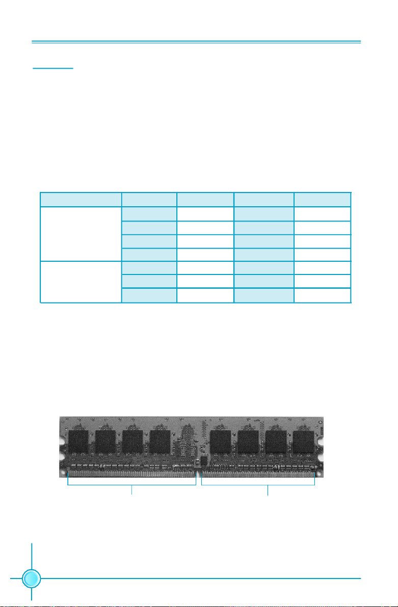
Installation of DDR2 Memory
1.There is only one gap near the center of the DIMM slot, and the memory
module can be fixed in one direction only. Unlock a DIMM slot by pressing the
module clips outward.
2.Align the memory module to the DIMM slot, and insert the module vertically
into the DIMM slot.
Populated
Populated
Populated
Populated Populated
128 Pins
3.The plastic clips at both sides of the DIMM slot will lock automatically.
14
112 Pins
Page 22

Chapter 2 Installation Instructions
Warning :
Be sure to unplug the AC power supply before adding or removing
expansion cards or other system peripherals, especially the
memory devices, otherwise your motherboard or the system
memory might be seriously damaged.
For the detailed memory support list on this motherboard, please visit the
website: h
ttp://www.foxconnchannel.com
15
Page 23
Chapter 2 Installation Instructions
Power Supply
This motherboard uses an ATX power supply. In order to avoid damaging any
devices, make sure that they have been installed properly prior to connecting
the power supply.
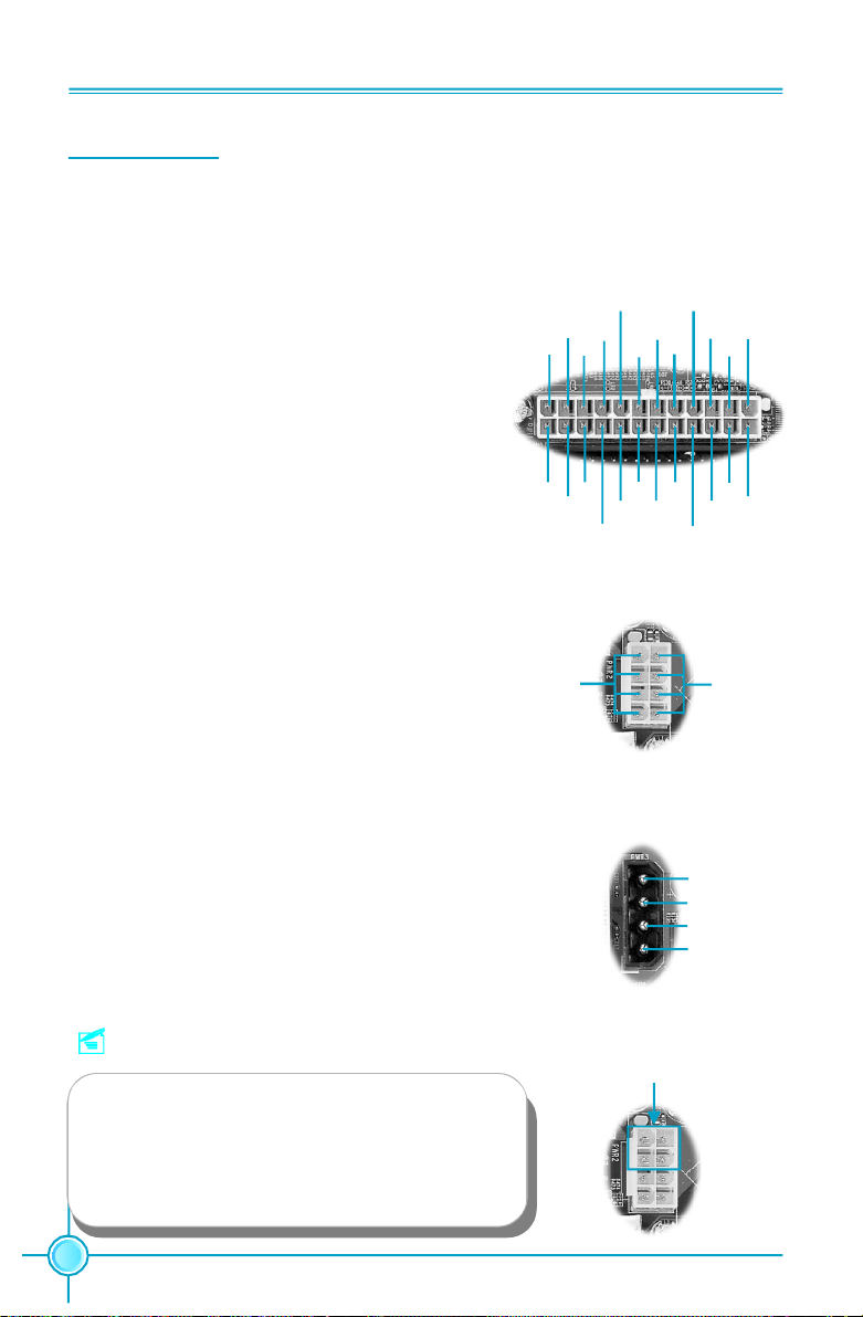
24-pin ATX power connector: PWR1
PWR1 is the ATX power supply connector. Make
sure that the power supply cable and pins are
properly aligned with the connector on the
motherboard. Firmly plug the power supply cable
into the connector and make sure it is secure.
24-pin ATX Power Connector
RSVD
GND
24
12
+3.3V
+5V
+12V
+5V
+12V
+
+5V
5V_AUX
GND
GND
PWROK
GND
+5V
PS-ON
+3.3V
GND
GND
-12V
13
1
+3.3V
GND
+3.3V
GND
+5V
8-pin ATX_12 V Power Connector: PWR2
The 8-pin ATX 12V power supply connects to
PWR2 and provides power to the CPU.
Exclusive Graphics Power Connector: PWR3
This connector is a auxiliary power for graphics
card. Exclusive power for graphics card is for bet-
ter graphics performance and for future upgrade
usage.
Note:
We strongly recommend that you use 8-pin ATX
12V power supply. If you want to use 4-pin
power supply, connect the 4-pin power con-
nector as shown.
8-pin ATX_12 V Power Connector
5
12V
8
Exclusive Graphics Power Connector
4
1
Connect a 4-pin
power plug here
5
8
1
GND
4
+5V
GND
GND
+12V
1
4
16
Page 24

Chapter 2 Installation Instructions
Other Connectors
This motherboard includes connectors for FDD devices, IDE devices, Serial ATA
devices, USB devices, and others.
FDD Connector: FLOPPY
This motherboard includes a standard FDD connector, supporting 360K, 720K,
1.2M, 1.44M, and 2.88M FDDs.
IDE Connector: PIDE
The IDE connector supports Ultra ATA 133/100/66 IDE hard disk drives. Con-
nect the cable’s blue connector to the IDE connector, then connect the gray
connector to the slave device (hard disk drive) and the black connector to the
Ultra ATA master device. If you install two hard disks, you must configure the
second drive as a slave device by setting its jumper accordingly. Refer to the hard
disk documentation for the jumper settings.
Attention:
Ribbon cables are directional, therefore, make sure to always
connect with the cable on the same side as pin 1 of the PIDE or
FLOPPY connector on the motherboard.
17
Page 25
Chapter 2 Installation Instructions
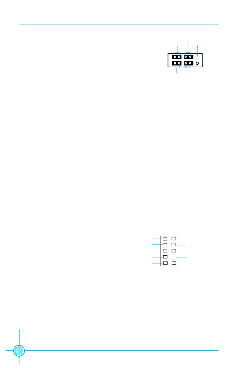
Front Panel Connector: FP1
This motherboard includes one connector for con-
PWRLED
+ -
PWRSW
Empty
necting the front panel switch and LED indicators.
1
+ -
NCHD-LED
RESET
HDD LED Connector (HDD-LED)
FP1
The connector connects to the case’s HDD indicator LED indicating the activity
status of hard disks.
Reset Switch (RESET)
Attach the connector to the Reset switch on the front panel of the case; the
system will restart when the switch is pressed.
Power LED Connector (PWRLED)
Attach the connector to the power LED on the front panel of the case. The Power
LED indicates the system’s status. When the system is in S0 status, the LED is
on. When the system is in S1, S3, S4, S5 status, the LED is off.
Power Switch Connector (PWRSW)
Attach the connector to the power button of the case. Pushing this switch allows
the system to be turned on and off rather than using the power supply button.
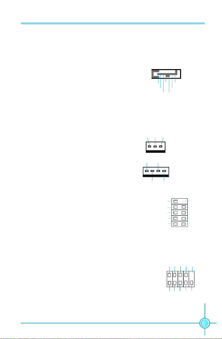
Audio Connector: F_AUDIO
The audio connector supports HD audio standard. It provides two kinds of
audio output choices: the Front Audio,
the Rear Audio. Front Audio supports
re-tasking function.
18
PORT1_L
PORT1_R
PORT2_R
SENSE_SEND
PORT2_L
1
F_AUDIO
AUD_GND
PRESENCE_J
SENSE1_RETURN
Empty
SENSE2_RETURN
Page 26
Chapter 2 Installation Instructions
Serial ATA II Connectors: SATA_1, SATA_2,
SATA_3, SATA_4, SATA_5, SATA_6
The Serial ATA II connector is used to connect
the Serial ATA II device to the motherboard. These
connectors support the thin Serial ATA II cables
for primary storage devices. The current Serial
ATA II interface allows up to 300MB/s data trans-
fer rate.
These six serial ATA connectors support RAID 0,
RAID 1, RAID 5, RAID 0+1 and JBOD
Fan Connectors: CPU_FAN, SYS_FAN, FAN
The fan speed can be detected and viewed in
“PC Health Status” section of the CMOS Setup.
These fans will be automatically turned off after
the system enters S3, S4 and S5 mode.
1
GND GND
GND
TX+
RX-TX-
SATA II Connector
SENSE
+12VGND
1
SENSE
GND
1
POWERCONTROL
RX+
SYS-FAN
FAN
CPU_FAN
USB Headers: F_USB1, F_USB2
Besides six USB ports on the rear panel, the
series of motherboards also have two 10-pin
headers on board which may connect to front
panel USB cable (optional) to provide additional
four USB ports.
Additional COM Connector: COM1 (optional)
This motherboard provides an additional serial
COM header for your machine.
Connect one side of a switching cable to the
header, then attach the serial COM device to the
other side of the cable.
NC
GND
D+
D-
5V_DUAL
F_USB 1/2
2
1
DTR#
DSR# SIN
SOUT
Empty
D-
1
CTS#
Empty
GND RLSD RI#
RTS#
COM1
GND
D+
5V_DUAL
10
9
19
Page 27

Chapter 2 Installation Instructions
IEEE 1394a Connector: F_1394_1 (optional)
The 1394 expansion cable can be connected to either
the front (provided that the front panel of your chassis
is equipped with the appropriate interface) or real
panel of the chassis.
GND
+12V
TPB -
GND
TPA -
9
10
12
F_1394_1
Empty
+12V
TPB +
GND
TPA +
Speaker Connector: J1E1
The speaker connector is used to connect speaker of
the chassis.
1
J1E1
GND
SPKR
+3.3V
20
Page 28

Chapter 2 Installation Instructions
Expansion Slots
This motherboard includes two 32-bit master PCI bus slots, one PCI Express
x 1 slot, one PCI Express x4 slot and two PCI Express x 16 slots.
PCI Slots
The expansion cards can be installed in the two PCI slots. PCI slots support
cards such as a LAN card, USB card, SCSI card and other cards that comply
with PCI specifications.
PCI Express x1 Slot
This motherboard has one PCI Express x1 slot that designed to accommodate
less bandwidth-intensive cards, such as a modem or LAN card.
PCI Express x4 Slot
This motherboard has one PCI Express x4 slot that designed to accommodate
less bandwidth-intensive cards, such as a modem or LAN card.
PCI Express x16 Slots
This motherboard has two PCI Express x16 slots that reserved for graphics or
video cards. The difference in bandwidth between the x16 and x1 slots is no-
table to be sure, with the x16 slot pushing 4GB/sec (8GB/sec concurrent) of
bandwidth, and the PCI Express x1 slot offering 250MB/sec.
This motherboard design enables the support of dual PCI-Express graphics
cards technology such as “SLI technology” and multiple display.
For the detailed PCI Express x16 graphics cards support list on this
motherboard, please visit the website: http://www.foxconnchannel.com
21
Page 29

Chapter 2 Installation Instructions
Jumpers
The users can change the jumper settings on this motherboard if needed. This
section explains how to use the various functions of this motherboard by chang-
ing the jumper settings. Users should read the following content carefully prior to
modifying any jumper settings.
Description of Jumpers
1. For the jumpers on this motherboard, pin 1 can be identified by the silk-
screen printed “ ” next to it. However, in this manual, pin 1 is simply
labeled as “1”.
2. The following table provides some explanation of the jumper pin settings.
User should refer to this when adjusting jumper settings.
Jumper Diagram Definition Description
1
1
1
1
1
1
Clear CMOS Jumper: CLR_CMOS
The motherboard uses the CMOS RAM to store all
the set parameters. The CMOS can be cleared by
removing the CMOS jumper.
How to clear CMOS?
1. Turn off the AC power supply and connect pins 1
and 2 together using the jumper cap.
2. Return the jumper setting to normal (pins 2 and
3 together with the jumper cap).
3. Turn the AC power supply back on.
1-2 Set pin1 and pin2 closed
2-3 Set pin2 and pin3 closed
Closed Set the pin closed
Open Set the pin opened
NORMAL
(Default)
1 3 2
CLEAR
1 3 2
CLR_CMOS
22
Warning:
1. Disconnect the power cable before adjusting the jumper settings.
2. Do not clear the CMOS while the system is turned on.
Page 30

Chapter 3 BIOS Description
Chapter
This chapter tells how to change system settings through
the BIOS Setup menus. Detailed descriptions of the BIOS pa-
rameters are also provided.
This chapter includes the following information:
3
3
v Enter BIOS Setup
v Main Menu
v Standard CMOS Features
v Advanced BIOS Features
v Advanced Chipset Features
v Integrated Peripherals
v Power Management Setup
v PnP/PCI Configurations
v System Monitor
v Load Defaults
v Set Password
v Set User name
v Save & Exit Setup
v Exit Without Saving
23
Page 31

Chapter 3 BIOS Description
Enter BIOS Setup
The BIOS is the communication bridge between hardware and software,
correctly setting up the BIOS parameters is critical to maintain optimal system
performance. Power on the computer, when the following message briefly
appears at the bottom of the screen during the POST (Power On Self Test),
press <Del> key to enter the Phoenix-Award BIOS CMOS Setup Utility.
Press F1 to continue, DEL to enter Setup.
Note:
It is recommended that the default settings in the BIOS are not
changed. The user accepts all responsibility for any damage that
results from changing the default settings.
Main Menu
The main menu allows you to select from the list of setup functions and two exit
choices. User the arrow keys to select among the items and press <ENTER> to
accept or go to the sub-menu.
Main Menu
The items in the main menu are:
Standard CMOS Features
The basic system configuration can be setup through this menu.
24
Page 32

Chapter 3 BIOS Description
Advanced BIOS Features
The advanced system features and boot sequence can be setup through
this menu.
Advanced Chipset Features
Optimize system performance through this menu. Configure clocks, voltages,
memory timings, and more.
Integrated Peripherals
Onboard peripherals such as RAID, USB, and MAC control can be setup
through this menu.
Power Management Setup
Configure power management, power-on, and sleep features through this
menu.
PnP/PCI Configurations
The system’s Plug-and-Play and PCI configurations can be modified
through this menu.
System Monitor
Monitor the real-time system status of your PC, including temperature, voltage,
and fan speed.
Load Defaults
Load the NVIDIA LinkBoostTM Technology settings for LinkBoostTM enabled
systems. Load default system settings for standard systems.
Set Password
Set the password to access the BIOS menu.
Set User Name
Set the BIOS Welcome screen name.
Save & Exit Setup
Save settings and exit setup.
Exit Without Saving
Abandon all setting changes and exit setup.
25
Page 33

Chapter 3 BIOS Description
NVIDIA LinkBoost
TM
<STATUS>
This status appears at the bottom of the BIOS screen. <STATUS> can be:
Detected: System detects an LinkBoost capable components.
Not Detected: The LinkBoost components are not detected.
SLI-Ready Memory <STATUS>
This status appears at the bottom of the BIOS screen. <STATUS> can be:
Enabled: SLI-Ready memory detected and enabled.
Disabled: SLI-Ready memory detected but disabled.
Not Detected: SLI-Ready memory not detected.
26
Page 34

Chapter 3 BIOS Description
Standard CMOS Features
This sub-menu is used to set up the standard CMOS features, such as the date,
time, HDD model and so on. Use the arrow keys select the item to set up, and
then use the <PgUp> or <PgDn> keys to choose the setting values.
Standard CMOS Features Menu
Date
This option allows you to set the desired date (usually as the current day) with
the <day><month><date><year> format.
Day—weekday from Sun. to Sat., defined by BIOS (read-only).
Month—month from Jan. to Dec..
Date—date from 1st to 31st, can be changed using the keyboard.
Year—year, set up by users.
Time
This option allows you to set up the desired time (usually as the current time)
with <hour><minute><second> format.
IDE Channel 0 Master/Slave & SATA Channel 1/2/3/4/5/6 Master
These categories identify the HDD types of 1 IDE channel installed in the com-
puter system. There are three choices provided for the Enhanced IDE BIOS:
None, Auto, and Manual. “None” means no HDD is installed or set; “Auto” means
the system can auto-detect the hard disk when booting up; by choosing “Manual”
and changing Access Mode to “CHS”, the related information should be entered
manually. Enter the information directly from the keyboard and press < Enter>:
Cylinder number of cylinders Head number of heads
Precomp write pre-compensationLanding Zone landing zone
Sector number of sectors
27
Page 35

Chapter 3 BIOS Description
Award (Phoenix) BIOS can support 3 HDD modes: CHS, LBA and Large or Auto mode.
CHS For HDD<528MB
LBA For HDD>528MB & supporting LBA (Logical Block Addressing)
Large For HDD>528MB but not supporting LBA
Auto Recommended mode
Drive A
This option allows you to select the kind of FDD to be installed, including “None”,
[360K, 5.25 in], [1.2M, 5.25 in], [720K, 3.5 in], [1.44M, 3.5 in] and [2.88 M, 3.5 in].
Halt On
This category determines whether or not the computer will stop if an error is
detected during powering up.
All Errors Whenever the BIOS detects a nonfatal error, the system
will stop and you will be prompted.
No Errors The system boot will not stop for any errors that may
be detected.
All, But Keyboard The system boot will not stop for a keyboard error; but
it will stop for all other errors.
All, But Diskette The system boot will not stop for a diskette error; but
it will stop for all other errors.
All, But Disk/Key The system boot will not stop for a keyboard or disk
error, but it will stop for all other errors.
Memory
This is a Display-Only Category, determined by POST (Power On Self Test) of
the BIOS.
Base Memory The BIOS POST will determine the amount of base (or
conventional) memory installed in the system.
Extended Memory The BIOS determines how much extended memory
is present during the POST.
Total Memory Total memory of the system.
28
Page 36

Chapter 3 BIOS Description
Advanced BIOS Features
Advanced BIOS Features Menu
vRemovable Device Priority
This option is used to select the priority for removable device startup. After
pressing <Enter>, you can select the removable device using the <PageUp>/
<PageDn> or Up/Down arrow keys, and change the removable device priority
using <+> or <->; you can exit this menu by pressing <Esc>.
vHard Disk Boot Priority
This option is used to select the priority for HDD startup. After pressing
<Enter>, you can select the HDD using the <PageUp>/<PageDn> or Up/
Down arrow keys, and change the HDD priority using <+> or <->; you can
exit this menu by pressing <Esc>.
vNetwork Boot Priority
This option is used to select the priority for network startup. After pressing
<Enter>, you can select the network using the <PageUp>/<PageDn> or Up/
Down arrow keys, and change the network boot priority using <+> or <->; you
can exit this menu by pressing <Esc>.
vCPU Internal Cache
This option is used to enable or disable the CPU internal cache.
vQuick Power On Self Test
Enable to reduce the time for power on self test.
vFirst/Second/Third Boot Device
This option allows you to set the boot device’s sequence.
vBoot Other Device
With this function set to enable, the system will boot from some other
devices if the first/second/thrist boot devices failed.
29
Page 37

Chapter 3 BIOS Description
vBoot Up NumLock Status
This item defines if the keyboard Num Lock key is active when your system is
started.
vSecurity Option
When it is set to “Setup”, a password is required to enter the CMOS Setup
screen; When it is set to “System”, a password is required not only to enter
CMOS Setup, but also to start up your PC.
vAPIC Mode
This option is used to enable or disable APIC function.
vMPS Version Control For OS
This option is used to set up the version of MPS Table used in NT4.0 OS.
vFull Screen LOGO Show
This option allows you to enable or disable the full-screen logo.
30
Page 38

Chapter 3 BIOS Description
Advanced Chipset Features
Use this section to control chipset features, specifically clocks, voltages, and
memory timings.
Advanced Chipset Features Menu
vSystem Clocks
Use this menu to control system clocks (see System Clocks section
below).
vSystem Voltages
Use this menu to control system voltages (see System Voltages section
below).
vMemory Configuration
Use this menu to control memory settings (see Memory Configuration
section below).
vPCI Clocks
Use this menu to turn off the PCI clock on the unused PCI slot.
vLPC P2P P2P
Decoding mode for LPC and P2P.
vSSE/SSE2 Instructions
Enable or disable Stream SIMD Extensions.
vSystem BIOS Cacheable
Enable the memory cache function for BIOS.
31
Page 39

vLoad timing/voltage settings
Load timing and voltage settings from a profile.
vSave timing/voltage settings
Save timing and voltage settings to a profile.
System Clocks menu
F
requency Settings
vRef Clock (HTT)
Reference clock frequency.
Chapter 3 BIOS Description
vCPU Multiplier
The value of the CPU multiplier.
vPCIe Bus, Slot 1
The frequency of the PCI-Express Bus, Slot 1.
vPCIe Bus, Slot 2
The frequency of the PCI-Express Bus, Slot 2.
vSPP ßà MCP Ref Clock
The frequency of the reference clock between SPP and MCP chips.
HT Multiplier
vCPU ßà nForce SPP
The HT multiplier between the CPU and the SPP.
vnForce SPP à nForce MCP
The HT multiplier from the SPP to the MCP.
32
Page 40

vnForce SPP ß nForce MCP
The HT multiplier from the MCP to the SPP.
T Width
H
vCPU ß à nForce SPP
The HT width between the CPU and the SPP.
vnForce SPP ßà nForce MCP
The HT width between the SPP and the MCP.
System Voltages menu
Chapter 3 BIOS Description
vCPU
Voltage to the CPU
vMemory
Voltage to the DRAM
vHT CPUßà nForce SPP
Voltage of the HT link between the CPU and the SPP
vHT nForce SPP ßà MCP
Voltage of the HT link between the SPP and the MCP
vnForce SPP
Voltage of the nForce SPP
vnForce MCP
Voltage of the nForce MCP
vAuxiliary
Voltage of the SPP auxiliary
33
Page 41

Chapter 3 BIOS Description
Memory Configuration menu
vSLI-Ready Memory
Enable memory settings that are SLI-Ready (only functional with
DRAM that is SLI-Ready).
vMemory Timings
Use this menu to control memory timings (see Memory Timings section
below).
vDrive Strength setting
Use this menu to control drive strength settings (see Drive Strength set-
tings section below).
vDram on-die termination
Resistance of the on-die termination resistors.
vRead/Write queue bypass
Number of times to bypass the read/write queue.
vBypass Maximum
Max number of times that the oldest memory access request can be
bypassed.
v32 Byte Granularity
32/64 byte DRAM access granularity.
vNVMEM memory test
Run NVIDIA memory testing module during POST.
vDQS Training Control
Perform/Skip DQS training.
34
Page 42
Chapter 3 BIOS Description
vCKE base power down mode
Enable or disable CKE base power down mode.
vCKE power down control
CKE power down mode selection. It should be set to “per channel” for non
mobile systems.
vMemclock tri-stating
Memclock tri-stating during C3 and Alt VID.
vMemory Hole remapping
Enable or disable memory hole remapping.
vAuto Optimize Bottom IO
Auto optimize maximum DRAM size when kernel assigns PCI resources
done.
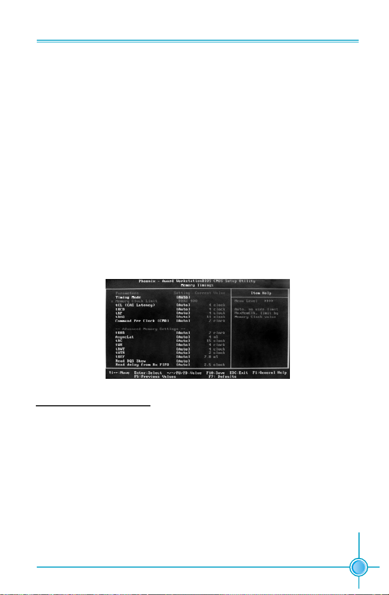
Memory Timings menu
S
tandard Memory Settings
vTiming mode
Select automatic or manual set memory timing.
vtCL (CAS Latency)
CAS Latency (CAS# to read data valid).
vtRCD
RAS# to CAS# delay for a RD/WR command to the same bank.
vtRP
Row Precharge time Precharge-to-Active or Auto-Refresh of the same bank.
35
Page 43

Chapter 3 BIOS Description
vtRAS
Minimum RAS# active time
vCommand Per Clock (CMD)
Command timing setting (per clock unit).
dvance Memory Settings
A
vtRRD
RAS# to RAS# delay of different banks.
vAsyncLat
Max round trip latency from the CPU to the DRAM.
vtRC
RAS# to RAS# or auto refresh time of the same bank.
vtWR
Write recovery time.
vtRWT
Minimum read to write turnaround time.
vtWTR
Minimum write to read delay with same chip select.
vtREF
DRAM refresh rate.
vRead DQS Skew
Read DQS delayed with respect to the data. 1/96 MEMCLK per unit.
vRead delay from Rx FIFO
Delay from DQS receiver enable to first data read from Rx FIFO.
36
Page 44

Chapter 3 BIOS Description
Drive Strength settings menu
vDRAM driver weak mode
DRAM data drive strength on DRAM.
vCKE drive strength
Drive strength of the CKE pins.
vCS drive strength
Drive strength of the CS and ODT pins.
vMA drive strength
Drive strength of the Address, RAS, CAS, WE, and parity pins.
vMCLK drive strength
Drive strength of the MEMCLK pins.
vMD drive strength
Drive strength of the Data pins.
vDQS drive strength
Drive strength of the DQS pins.
37
Page 45

Chapter 3 BIOS Description
Integrated Peripherals
Integrated Peripherals Menu
vIDE Function Setup
Use this menu to setup the data flow control for IDE.
vRAID Config
Use this menu to enable or disable SATA RAID.
vUSB Config
Use this menu to setup USB interface.
vMAC Config
Use this menu to turn off MAC.
vIEEE1394 controller
Use this setting to set whether the IEEE 1394 function is enabled.
vHD Audio
Use this setting to configure HD Audio.
vIDE HDD Block Mode
Use this setting to configure HDD Block Mode.
vOnboard FDC Controller
This option is used to set whether the Onboard FDC Controller is enabled.
vOnboard Serial Port 1
This option is used to assign the I/O address and IRQ for onboard serial port 1.
38
Page 46

Chapter 3 BIOS Description
Power Management Setup
Power Management Setup Menu
vACPI function
ACPI stands for “Advanced Configuration and Power Interface”. ACPI is a
standard that defines power and configuration management interfaces between an operating system and the BIOS. In other words, it is a standard that
describes how computer components work together to manage system
hardware. In order to use this function the ACPI specification must be supported by the OS (for example, Windows2000 or WindowsXP).
v ACPI Suspend Type
This option is used to set the energy saving mode of the ACPI function.
When you select “S1 (POS)” mode, the power will not shut off and the
supply status will remain as it is, in S1 mode the computer can be resumed
at any time. When you select “S3 (STR)” mode, the power will be cut off after
a delay period. The status of the computer before it enters STR will be saved
in memory, and the computer can quickly return to previous status when the
STR function wakes. When you select “S1 & S3” mode, the system will
automatically select the delay time.
v C States Support
CPU power state selection.
v Soft-Off by PBTN
This option is used to set the power down method. This function is only
valid for system using an ATX power supply.
When “Instant-Off” is selected, press the power switch to immediately
turn off power.
When “Delay 4 Sec” is selected, press and hold the power button for four
seconds to turn off power.
39
Page 47

Chapter 3 BIOS Description
vWOL(PME#) From Soft-Off
This item is used to set the system to wake-up on LAN.
vWOR(RI#) From Soft-Off
This item is used to set the system to wake-up on ring.
vAMD Cool ‘n’ Quiet[tm]
Use this option to enable or disable AMD Cool ‘n’ QuietTM Technology.
v Power-on by Alarm
This item is used to set the timing of the power-on function.
vPOWER ON Function
This option is used to set the power on method for your PC.
40
Page 48

Chapter 3 BIOS Description
PnP/PCI Configurations
PnP/PCI Configurations Menu
v Init Display First
This option is used to set which display device will be used first when your PC
starts up.
vReset Configuration Data
This option is used to set whether the system is permitted to automatically
distribute IRQ, DMA, and I/O addresses each time the machine is turned on.
vResources Controlled by
Use this option to determine if IRQ resources are automatically assigned or
manually assigned
vIRQ Resources
Press <Enter> to manually assign IRQ resources.
vPCI/VGA Pallette Snoop
If you use a non-standard VGA card, use this option to solve graphic acceleration card or MPEG audio card problems (e.g. colors not accurately displayed).
vMaximum Payload Size
This option is ued to set maximum TLP payload size for PCI Express devices.
vMaximum ASPM
Enable/Disable Advance State Power Management
41
Page 49

System Monitor
System Monitor Menu
Temperature values
vSystem
The temperature of the system.
vCPU
The temperature of the CPU.
vBoard
The temperature of the motherboard.
Chapter 3 BIOS Description
Voltage values
vCPU
The voltage of the CPU.
vMemory
The voltage of the Memory.
v+3.3V
The voltage of the +3.3V .
v+3.3V Dual
The voltage of the +3.3V Dual.
v+5V
The voltage of the +5V.
42
Page 50

Chapter 3 BIOS Description
vnForce MCP
The voltage of the nForce MCP chip.
vnForce SPP
The voltage of the nForce SPP chip.
vHT CPU <-> nForce SPP
The voltage of the HT between the CPU and the nForce SPP chip.
v+Vbat
The voltage of +Vbat.
Fan Speed values
vCPU Fan Speed
The CPU fan speed.
vMCP Fan Speed
The MCP fan speed.
vSys Fan Speed
The system fan speed.
43
Page 51

Chapter 3 BIOS Description
Load Defaults
The BIOS defaults sets the basic system functions that ensure system stability.
If the system is NVIDIA LinkBoostTM enabled, the default settings are the
LinkBoost settings.
If your computer cannot POST properly, you should load the Defaults to restore
the original settings.
Set Password
The password can be used to start the system or modify the CMOS settings.
When you select the Set Password option, the following message will appear in
the center of the screen:
Enter Password:
Enter your password, not exceeding 8 characters, then press <Enter>. The
password you enter will replace any previous password. When prompted, key in
the new password and press <Enter>.
If you do not want to set a password, just press <Enter> when prompted to
enter a password, and in the screen the following message will appear. If no
password is keyed in, any user can enter the system and view/modify the CMOS
settings.
Password Disabled!!!
Press any key to continue …
Set User Name
Set the name that will appear on the POST welcome screen.
Save & Exit Setup
When you select this option and press <Enter>, the following message will
appear in the center of the screen:
SAVE to CMOS and EXIT (Y/N)?Y
Press <Y> to save your changes in CMOS and exit the program; press <N> or
<ESC> to return to the main menu.
44
Page 52

Chapter 3 BIOS Description
Exit Without Saving
If you select this option and press <Enter>, the following message will appear
in the center of the screen:
Quit Without Saving (Y/N)?N
Press <Y> to exit CMOS without saving your modifications; press <N> or <ESC>
to return to the main menu.
45
Page 53

Chapter 4 Driver CD Introduction
Chapter
4
4
The utility CD that came with the motherboard contains use-
ful software and several utility drivers that enhance the
motherboard features.
This chapter includes the following information:
v Utility CD content
v Start to install drivers
46
Page 54

Chapter 4 Driver CD Introduction
Utility CD content
This motherboard comes with one Utility CD. To begin using the CD, simply
insert the CD into your CD-ROM drive. The CD will automatically displays the
main menu screen.
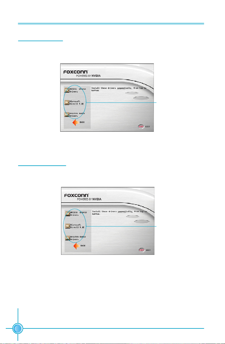
1. Install Driver
Using this choice, you can install all the drivers for your motherboard. You should
install the drivers in order and you need to restart your computer after the drivers
all installed.
A. NVIDIA nForce Driver B. Microsoft DirectX 9.0C
C. Realtek Audio Driver
2. Software
Use this option to install additional software programs.
A.NVIDIA nTune
B.Foxconn LiveUpdate
C.Adobe Acrobat Reader
D.Norton Internet Security
3. User Manuals
Click here to browse all user manuals content.
4. Browse CD
Click here to browse CD content.
5. Foxconn Website
Click here to visit Foxconn website.
47
Page 55
Chapter 4 Driver CD Introduction
Installing Divers
Click the drivers that you want to install and begin the setup steps.
Click here
Installing Utilities
You can select the utilities that you want to install and begin the setup steps.
48
Click here
Page 56

Chapter 4 Driver CD Introduction
Chapter
5
5
This chapter will introduce how to use attached software.
This chapter provides the following information:
v NVIDIA nTune 4.0
v Fox LiveUpdate
v MediaShield RAID Manager
v Network Access Manager
49
Page 57

Chapter 5 Directions for Bundled Software
NVIDIA nTune 4.0
NVIDIA nTuneTM is a utility for accessing, monitoring, and adjusting your system
components, including temperature and voltages, with clear, user-friendly con-
trol panels. Overclock your system for highest performance or underclock it for
near silent operation. All changes are performed within the Microsoft® Windows
interface, enabling full functionality without the need to make changes in the BIOS
and reboot your system.
nTune Category
To start NVIDIA nTune from the Desktop, select Start -> All Programs -> NVIDIA
Corporation -> nTune -> nTune. Once nTune is launched, the category view will
be available. To access nTune related features, select the nTune category.
®
50
Page 58

Chapter 5 Directions for Bundled Software
Side Panel
The nTune 4.0 Side Panel is located to the left
of every screen in nTune and provides access
to help, recently used tasks, related tasks, and
pending changes. Each of these are explained
more below.
Help
From here, you can access help screens,
search help, or go to the NVIDIA website for
assistance.
Recent Tasks
Quickly toggle back to previous task pages by
selecting them from the Recent Tasks menu
in the left pane.
Related Tasks
Tasks that are related to the page being viewed
are listed in the Related Tasks menu. From
here, you may quickly jump to a related task by
selecting them from the Related Tasks menu in the left pane.
Pending Changes
When any changes have been made on a page, they can be applied or can-
celled here by selecting Apply or Cancel.
Load or Save Profile
By selecting Profile, the user may then select to either Load a profile directly, or
Save the current changes to a new profile.
51
Page 59

Chapter 5 Directions for Bundled Software
nTune Task View
After selecting the nTune category, the task list is presented. Each of the tasks are
grouped into two categories: System Performance and System Diagnostics.
The tasks available under these categories include:
v Performance tuning wizard
v Manage profile rules
v Adjust speeds and timings
v Diagnose system performance
v Adjust NVIDIA Monitor settings
v Adjust NVIDIA logging settings
Performance Tuning Wizard
The NVIDIA nTuneTM performance manager allows automatic tuning for optimal
performance and the ability to customize. Once configured, nTune automatically
chooses the right system settings for the application that is being run based on
your saved profiles and personal rules.
52
Page 60

Chapter 5 Directions for Bundled Software
The Quick method takes approximately 20 minutes to run while it adjusts system
bus speeds and parameters. It first saves current bus speeds as the Default.npe
file. After performing a CPU intensive micro-benchmark, to ensure the system tem-
perature stays low while fan noise is reduced, it saves a second file named Silent.
npe. Finally, it ratchets up the bus speeds, runs micro-benchmark, and optimizes
the system, saving those settings as a best system.npe file.
The Complete method takes approximately 60 minutes to perform a more thorough
performance analysis. It will create default, silent, and best system files much in the
same way as the quick process. Due to the additional complexity, additional passes
may be required.
The Expert method allows users to manually select a test or group of tests, using
the run button to start the tests. A progress bar will appear when the benchmarks
are being executed. The user may cancel the tests at any time.
53
Page 61

Chapter 5 Directions for Bundled Software
Manage Profile Rules
This task is used to assign specific applications to specific profiles. Each time the
application is launched, the assigned profile will go into effect.
The profile menu may be pulled down to select a different profile. The list will be
built from profiles currently existing in the profile directory. Choose profile may
also be selected and will launch an explorer window. New applications may be
added to the action list by selecting New application from the list window. Actions
may be removed by selecting it from the list and pressing the <Delete> key.
Select Start rules after applying changes to begin using them.
Adjust Clock Speeds and Timings
These controls allow the bus speeds to be adjusted manually to increase perfor-
mance for gaming, or lower performance to conserve power and create a quieter
user environment. The number to the right of the slider is the new bus speed that
will be applied. Adjustments can be made by using the mouse to drag the slider.
All changes will take effect immediately after selecting Apply; however, these
setting will only remain active for the current Windows session. This will allow a
user to safely return to Windows in the event of a crash, without any possibility of
boot issues since the changes are not made directly to the BIOS settings.
54
Page 62

Chapter 5 Directions for Bundled Software
Diagnose System Performance
This task is used to quickly diagnose potential system performance issues and
relay valuable troubleshooting data to technical support. nTune performs a series
of quick checks to identify probably causes of performance issues and then creates
a list of the results, providing recommendations for improvements. The Save button
is used to save the system information details in a log file that can then be provided
to tech support.
55
Page 63

Chapter 5 Directions for Bundled Software
System Stability Category
To access System Stability related features, select the System Stability category.
System Stability Task View
After selecting the System Stability category, a task list is presented. Under the
Diagnostics heading, the tasks available include “View the system status” and
“Perform a stability test”.
56
Page 64

Chapter 5 Directions for Bundled Software
View System Status
The status of the system including current system clock speeds, system tempera-
tures, memory timings, and system voltages is presented with View System Status.
Specific settings that can be checked include:
v CPU speed and multiplier
v HyperTransport link multiplier
v PCI Express bus speed
v Front side bus speed (FSB)
v GPU memory bus speed
v GPU core bus speeds for 2D and 3D
v Memory bus speeds
v CPU, GPU and system temperatures and fan speeds
v Voltage settings for CPU, PCI Express, Memory, and GPU Core
Perform Stability Test
Once system settings have been modified using NVIDIA nTune, it is important to
perform a stress test of the entire system to ensure system stability.
57
Page 65

Chapter 5 Directions for Bundled Software
The following system components can be verified for stability: CPU, Memory, PCI-E
bus, Disk, Network, and GPU. Each of these or all of these, depending on what
components are selected, can be tested using a selected profile or current system
settings. Once the components and settings are selected, the stress test can be
set to run for a duration of 10/30/60 minutes or 2/6/12/24/48 hours.
nTune 4.0 NVMonitor
NVMonitor lets you monitor system performance, bus speeds, temperature and
voltages using dynamic graphs. To start NVMonitor from the Desktop, select Start
-> All Programs -> NVIDIA Corporation -> nTune -> NVIDIA Monitor.
58
Page 66

Chapter 5 Directions for Bundled Software
NVMonitor displays performance for individual components including CPU, Network,
Disk, and Memory. Bus speeds for CPU, Memory, HyperTransport (HT), and PCI
Express (PCX) can be monitored along with temperature and voltages. The current
profile is displayed alongside the SMART hard drive status if that has been enabled
in the system BIOS.
Adjust NVIDIA Monitor Settings
The settings window allows a number of adjustments to be made to NVMonitor.
The following can be specified: the temperature reading interval, the transparency
level of the NVMonitor so that background information may be viewed through it, the
ability to keep NVMonitor always on top so it cannot be hidden by other tasks,
temperature tracking by components, showing temperature in Celsius or
Fahrenheit, and the ability to set over temperature conditions using audio, message,
or visual signals. S.M.A.R.T. messages for hard drives can also be monitored by
NVMonitor.
59
Page 67

Chapter 5 Directions for Bundled Software
Fox LiveUpdate
Fox LiveUpdate is a useful utility for backuping and updating the system BIOS,
drivers and utilities by local or online.
Supported Operating Systems:
-Windows 2000
-Windows XP (32-bit and 64-bit)
-Windows 2003 (32-bit and 64-bit)
Using Fox LiveUpdate:
1.1 Local Update - BIOS Info.
This page lets you know your system BIOS information.
60
Toolbar
Link to website
Minimum
Exit
Show current
BIOS information
Page 68

Chapter 5 Directions for Bundled Software
1.2 Local Update - Backup
This page lets you backup your system BIOS. Click “Backup”, then give a name.
Click “Save” to finish the backup operation.
Key in a BIOS name
Click here
1.3 Local Update - Update
This page lets you update your system BIOS from Internet. After click “Update”,
there will show warning message, please read it carefully. If you still want to
continue, click “Yes”. Then load a local BIOS file and follow the wizard to finish the
operation.
Note:
Fox LiveUpdate will auto backup BIOS before update because we
have enabled this function in Configure option.
61
Page 69

Chapter 5 Directions for Bundled Software
2.1 Online Update - Update BIOS
This page lets you update your system BIOS from Internet. Click “start”, it will
search the new BIOS from Internet. Then follow the wizard to finish the update
operation.
Click here
Current information
Search new BIOS
from Internet
Select BIOS to update
62
Browse detail
information
Update BIOS
Close the window
Page 70

Chapter 5 Directions for Bundled Software
2.2 Online Update - Update Driver
This page lets you update your system drivers from Internet. Click “start”, it will
search the new drivers from Internet. Then follow the wizard to finish the update
operation.
Click here
Current information
Search new drivers
from Internet
Select the drivers to update
Browse detail
information
Install the selected
drivers
Close the window
63
Page 71

Chapter 5 Directions for Bundled Software
2.3 Online Update - Update Utility
This page lets you update utilities from Internet. Click “start”, it will search the new
utilities from Internet. Then follow the wizard to finish the update operation.
Click here
Current information
Search new utilities
from Internet
2.4 Online Update - Update All
This page lets you update your system drivers from Internet. Click “start”, it will
search all new BIOS/drivers/utilities from Internet. Then follow the wizard to finish
the update operation.
64
Click here
Current information
Search all new
BIOS/drivers/utilities
from Internet
Page 72

Chapter 5 Directions for Bundled Software
3.1 Configure - option
This page lets you set auto search options. After your setting, the utility will start
searching and related information will show on the task bar.
Click here
Set auto
search options
Select search
which kind of
versions
Apply the changes Reset to default value
Note:
When enable auto search function, Fox LiveUpdate will appear search-
ing result on task-bar. Double click the icon, you can see the detail
information.
Double click here
65
Page 73

Chapter 5 Directions for Bundled Software
3.2 Configure - System
This page lets you set the backup BIOS location and change different skin of
the utility.
Click here
Set the location of
download files or
auto backup BIOS
Select different skin
of the software
Determine if the Fox LiveUpdate
can auto run when the system
starts up
Apply the changes
Reset to default value
4. About & Help
This page shows some information about Fox LiveUpdate.
Click here
66
Show information
about Fox LiveUpdate
Page 74

Chapter 5 Directions for Bundled Software
MediaShield RAID Manager
MediaShield RAID Manager allows a user to:
v Create RAID Arrays
v View RAID Arrays
v Delete RAID Arrays
v Set up a spare RAID disk
v Morph RAID Arrays
v Hot Plug Array
The following sections give an overview of how to create/view/delete an array,
and how to set up a spare RAID disk.
Morphing RAID arrays and Hot Plugging arrays are advanced user functions
that are explained in detail in the MediaShield User Guide available for
download on www.nvidia.com
Create RAID Arrays
This section covers use of the MediaShield Creation Wizard. This wizard will
step through configuration of your available storage.
As shown in Figure 1, the Wizard’s Welcome screen lists the disks that are
available for configuration.
.
Figure 1. MediaShield Creation Wizard Welcome Screen
67
Page 75

Chapter 5 Directions for Bundled Software
1. Click Next to go to the following screen:
Figure 2. MediaShield Select-Configuration Screen
Note: You will only see this screen if you have less than 4 free disks in the
system. If there are 4 or more free disks available, you will proceed to directly
to custom setup.
Selecting the “Protection” option will automatically configure the best RAID
option based on the number of drives and with the criteria that if a drive fails
you will not lose your data.
Selecting the “Capacity”option will automatically configure the best RAID
option based on the number of drives and the desire for maximum capacity.
This array will NOT be fault-tolerant, so choose this option only if your data is
non-critical or is being backed up.
Select the “Custom” option to create a custom RAID array that can be a:
v Striped Array
v Mirrored Array
v Stripe Mirrored Array
v Spanning Array
v RAID 5 Array
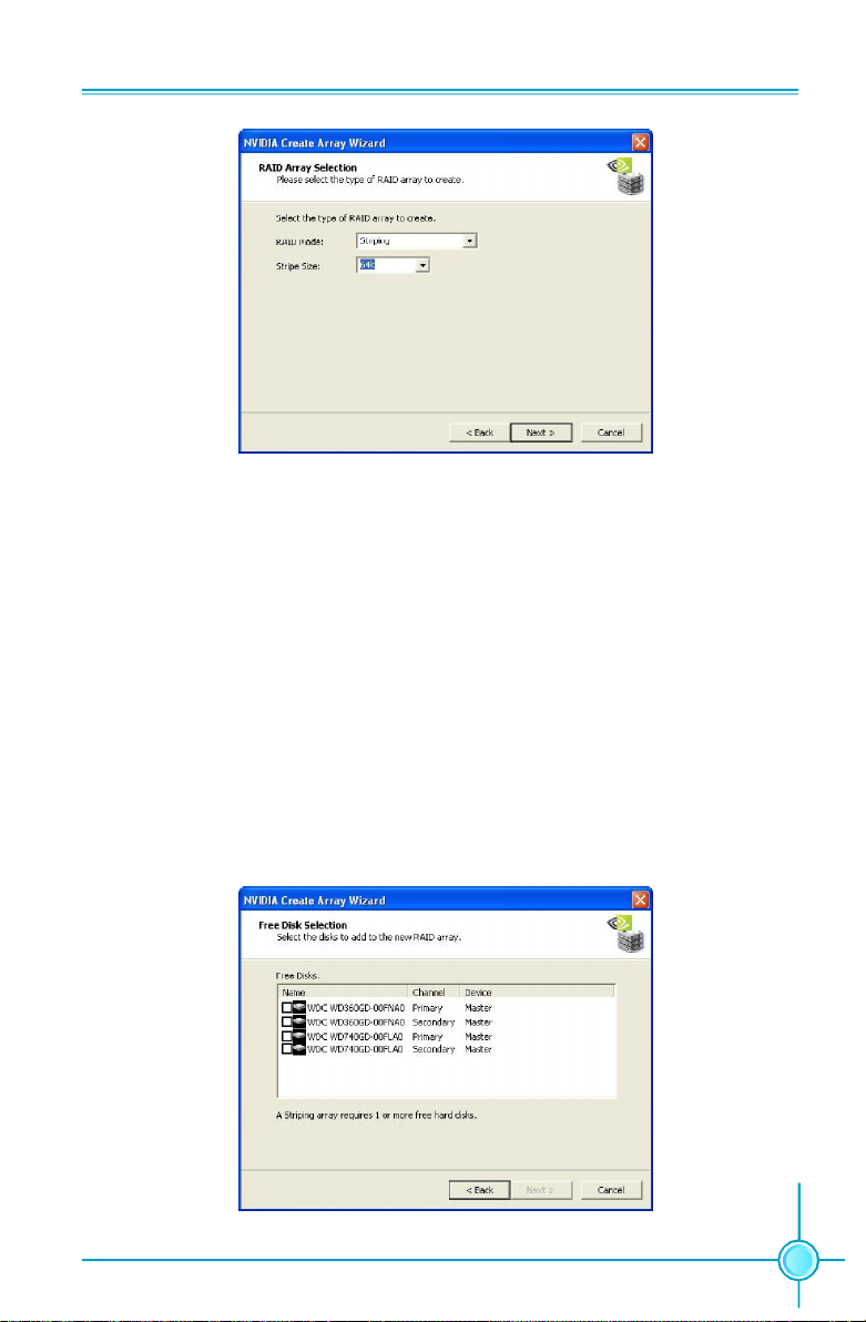
To set up a Striped Array, select “Striping” as RAID Mode and leave “Stripe
Size” with its default value, as shown in Figure 3.
68
Page 76
Chapter 5 Directions for Bundled Software
Figure 3. Creating a Striped Array
To select a Mirrored Array, select “Mirroring” as RAID mode and leave Stripe Size as
default.
To select a Striped Mirror Array, select “Stripe Mirroring” as RAID Mode and leave
Stripe Size as default.
To select a Spanning Array, select “Spanning” as RAID Mode and leave Stripe Size
as default.
To select a RAID 5 Array, select “RAID 5” as RAID Mode and leave Stripe Size as
default.
After selecting RAID Mode, click Next, and the following screen will appear:
Figure 4. Selecting Disks
69
Page 77
Chapter 5 Directions for Bundled Software
Select the disks you want to include in the Stripe set. Follow the next couple to
complete creating the Array.
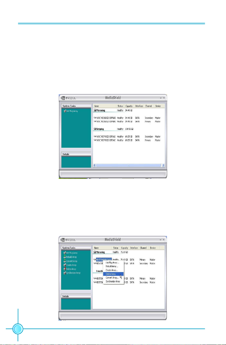
View RAID Arrays
To view your RAID configuration from Windows, launch the MediaShield RAID Man-
agement utility by double-clicking MediaShield. The RAID configuration information
appears in the right-side pane, as shown in Figure 5.
Figure 5. Viewing RAID Arrays
Delete RAID Arrays
To delete an Array do the following:
1. Launch the MediaShield application and right click on the RAID array that you
want to delete (assuming that you have a RAID array already created) as shown in
the following screen shot:
70
Page 78

Chapter 5 Directions for Bundled Software
Follow the next couple of screens to complete Deleting the Array.
As shown in Figure 7, the array has been deleted and we see only free disks.
Figure 7. RAID Array deleted
Setting Up a Spare RAID Disk
You can designate a hard drive to be used as a spare drive for a RAID 1, RAID 0+1
or RAID 5 array2. The spare drive can take over for a failed disk. MediaShield RAID
supports two types of spare drives:
Free Disk
A free disk is a disk that is not part of any RAID array, but can be used by any
available RAID 1, RAID 0+1, or RAID 5 array that requires a particular disk when
one of its disks crashes or becomes unusable. The process is automatic and
doesn’t require any userinteraction.
Dedicated Disk
A dedicated free disk is a disk that is assigned to a RAID 1, RAID 0+1, or RAID 5
array and that disk is used by that array only when needed, for example during a
system crash where a RAID mirrored drive is broken. The dedicated disk can be
used only by the array that it is assigned to and not by any other array.
Note: You must have at least two RAID arrays to use this feature.
71
Page 79

Chapter 5 Directions for Bundled Software
Assigning a Free Disk
To mark a disk as free, or not a part of any array, do the following:
1. Enter the system BIOS setup and make sure that the drive that you want to mark
as free is RAID enabled.
2. Enter the RAID BIOS and make sure that the drive is not part of any array (if one
exists).
3. Boot into Windows and run the MediaShield program.
The drive appears under the Free Disk section.
Figure 8. Free Disks
Assigning a Dedicated Disk
To mark a disk as dedicated, or reserve it for use by a specific array, you must have
at least one free disk and you must also have at least two RAID 1, RAID 0+1, or RAID
5 arrays created.
1. To dedicate a free disk to an array, right click the array as shown in Figure 9.
72
Page 80

Chapter 5 Directions for Bundled Software
Figure 9. Dedicating a Disk to an Array
2. Select Designate Spare from the menu to launch the Spare Disk Allocation Wizard.
Figure 10. Disk Allocation Wizard
3. Click Next.
The Free Disk Selection page appears.
73
Page 81

Chapter 5 Directions for Bundled Software
Figure 9. Dedicating a Disk to an Array
4. From the Free Disk Selection page, select a free disk. This disk will be designated
to the array.
74
Page 82

Chapter 5 Directions for Bundled Software
Network Access Manager
The NVIDIA® ForceWare® Network Access Manager (NAM) application helps you
easily configure and control NVIDIA networking hardware and software, gather
statistics, and monitor logs.
When you launch NAM for the first time, the following GUI appears.
Settings for Network Access Manager
As shown in the previous screenshot, these entries are available in NMA.
vEthernet: This entry controls the configuration of the Ethernet interface, such as
Ethernet speed, whether the connection is full-duplex or half-duplex, and so
on.
Note: Two Ethernet settings appear if your hardware supports two Ethernet
ports; otherwise, only one setting appears.
75
Page 83

Chapter 5 Directions for Bundled Software
vTeaming: Teaming controls load balancing and fail-over between two Ethernet
ports.
vLogs: This setting enables/disables logging of various setting, such as Ethernet
and teaming.
vTCP/IP Acceleration: This entry enables or disables TCP/IP acceleration and
configuration. When TCP/IP acceleration is enabled, it lowers the CPU utilization
and provides overall better system performance when the networking traffic is
mainly TCP/IP.
vFirstPacket: FirstPacket enables/disables traffic prioritization and bandwidth
control. This capability provides a better gaming experience over a broadband
connection when multiple applications on the same PC are simultaneously
transmitting data to the Internet.
vAdministration: Administration, located at the top of the page, controls various
system settings, such as font, font size, and whether remote administration is
turned on or off.
Ethernet
You can change various Ethernet settings on this page, such as Speed, Remote
Wakeup, Checksum Offload, and more.
76
Page 84
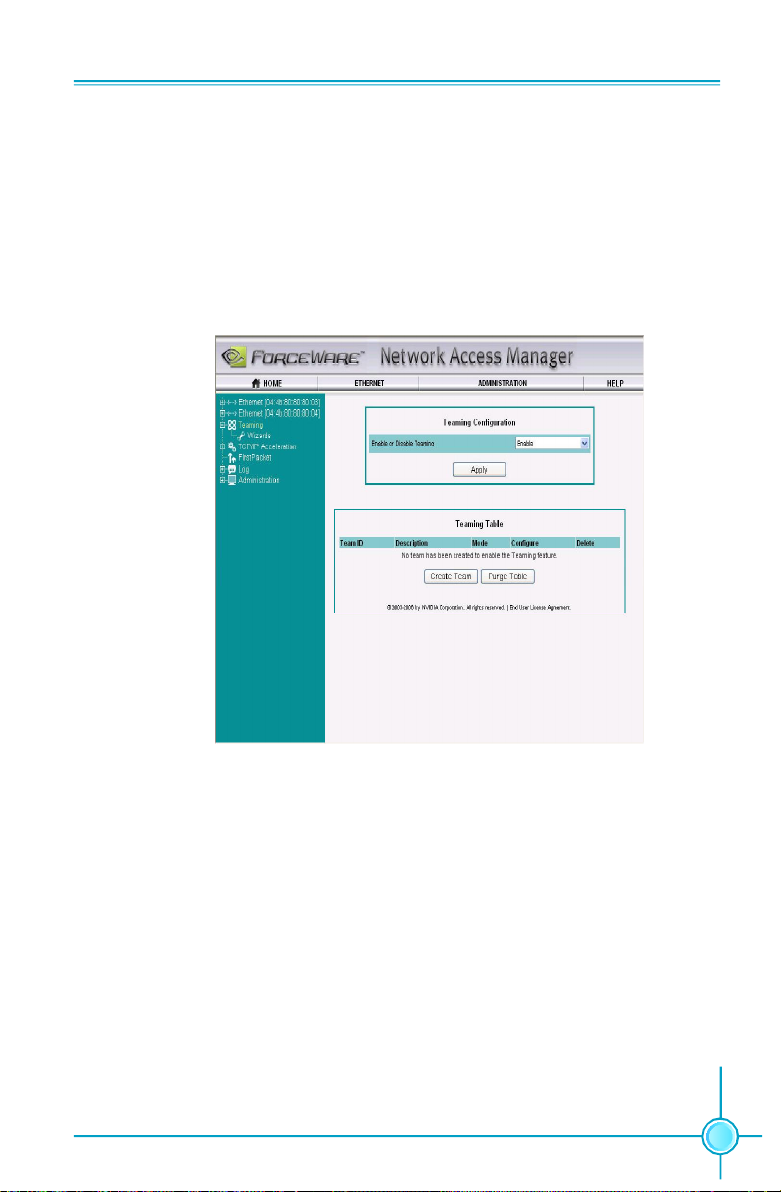
Chapter 5 Directions for Bundled Software
Teaming
What It Does
Teaming is the ability to provide load balancing and fail-over between two Ethernet
ports. When this feature is enabled and configured properly, one IP address is
visible on the network, and all networking traffic is distributed between the two
Ethernet ports, depending on the Teaming mode of operation selected, as ex-
plained in the following topics.
Its Modes of Operation
Load Balance and Failover
When load balancing is configured over a collection of Ethernet interfaces, the
collection is commonly known as a “team” or “bundle”.
vWithin a team, there is a primary Ethernet interface that has special responsibilities.
For example, it receives all multicast (and broadcast) traffic, and it transmits all
outbound unicast traffic not destined for the subnet to which the team is attached
(this traffic will later be referred to as non-local unicast traffic).
vThe secondary Ethernet interfaces are available for load balancing of traffic to and
from local machines (other machines within the same IP subnet to which the
team is attached).
77
Page 85

Chapter 5 Directions for Bundled Software
Failover Only
Load balancing (LB) is frequently used in conjunction with “failover” (FO), although
it is possible to use failover alone. For instance, one Ethernet interface might be
dedicated as a “hot standby” in the event that the primary Ethernet interface fails.
Team Mode: IEEE 802.3ad
In 802.3ad, all the team members share a common MAC address. Other machines
only know one MAC address for this machine’s IP address, so all its connections
have to be sent to the MAC address it knows for this machine’s IP address.
Transmit-Only Load Balance and Failover
In a TX-only configuration, all the incoming (RX) traffic is received into one Ethernet
interface, and the outgoing (TX) traffic is balanced across the available Ethernet
interfaces.
Logs
When logging is enabled and properly configured, you can log various information
about the networking configuration - for example, you can track whether an Ethernet
interface is enabled and working properly, or whether teaming is enabled.
78
Page 86

Chapter 5 Directions for Bundled Software
TCP/IP Acceleration
When TCP/IP acceleration is enabled and configured properly, most of the TCP/IP
traffic is processed in hardware by the media and communications (MCP) chip. The
advantage this technology offers is that it lowers the CPU utilization, which leads to
overall better system performance since the CPU has more free cycles to focus on
other tasks.
FirstPacket
FirstPacketTM provides an advanced level of outbound network traffic prioritization
for broadband network connections such as DSL and cable modem. When this
feature is enabled and configured properly, you can, among other capabilities,
assign all gaming/VOIP (Voice Over IP) traffic to have a higher priority than file
transfer or peer to peer traffic-leading to faster throughput and lower latency for the
higher priority applications.
79
Page 87

Chapter 5 Directions for Bundled Software
Administration
In the Administration area, you can change various parameters of the Web GUI,
manage remote access, reset the software to its default setting, and more.
Summary
Network Access Manager is an easy-to-use Web interface that provides all the
networking configuration, monitoring, and logging that users demand.
For more information about NAM, please read the ForceWare Networking and
Firewall Administrator's Guide.
80
Page 88

Chapter 6 Appendix
Chapter
6
6
This chapter will introduce how to use attached software.
This chapter provides the following information:
v NVIDIA SLITM technology
v NVIDIA RAID
v Audio Configuration
v On board LED Code Table
81
Page 89

Chapter 6 Appendix
NVIDIA SLITM Technology
1. Introduction
NVIDIA® SLITM (Scalable Link Interface) technology takes advantage of the increased
bandwidth of the PCI ExpressTM bus architecture, and features intelligent hardware
and software solutions to deliver earth-shattering PC performance in a multi NVIDIA
GPU solution.
NVIDIA® nForceTM5 SLI MCPs (media and communications processors) offer blister-
ing graphics performance and overall PC performance for both AMD and Intel
platforms. With the power of SLITM technology you get the ability to connect two NVIDIA
SLI-Ready PCI ExpressTM graphics cards for mind-blowing game play with brilliant
and intensive 3D graphics.
2. Using SLI
Step1. Install two SLI-Ready Graphic cards on the two PCI Express x16 slots.
TM
Technology
82
Page 90

Chapter 6 Appendix
Step2. Connect power extension cable to the graphics card power connector and
power supply connector.
Power Extension
cable
Step 3. Install the SLI Bridge Board to the goldfingers on each graphics card. Make
sure that the connector is firmly in place.
Step 4. Connect the 4-pin ATX power cable to the Auxiliary power connector to secure
the system is stable.
Step 5. Power on your computer and boot into Operating System.
Step 6. Install the NVIDIA graphics card drivers and restart your computer.
83
Page 91
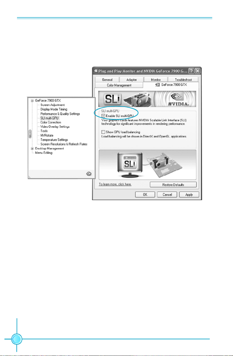
Chapter 6 Appendix
Step 7. Right-click the mouse --> Select “Properties”--> Select “Setting” --> Click
“Advanced” --> Select “GeForce xxxx xxx” --> Click “SLI multi-GPU” --> Click “Enable
SLI multi-GPU”.
84
Page 92

Chapter 6 Appendix
NVIDIA RAID
RAID Arrays
This section describes the following types of RAID arrays that NVIDIA RAID
supports:
v RAID 0
RAID 0 defines a disk striping scheme that improves the disk read and write
times for many applications.
vRAID 1
RAID 1 defines techniques for mirroring data.
vRAID 0+1
RAID 0+1 combines the techniques used in RAID 0 and RAID 1 arrays.
vRAID 5
RAID 5 provides fault tolerance and better utilization of disk capacity.
vSpanning (JBOD)
JBOD provides a method for combining drives of different sizes into one large
disk.
Summary of RAID Configurations
Array
RAID 0
RAID 1
RAID
0+1
RAID 5
JBOD
Advantages
High data throughput.
100% data redund-
ancy.
Optimized for both
100% data redun-
dancy and per-
formance. Allows
spare disks.
Fault tolerance and
better utilization of disk
space.
ombines and uses the
capacity of odd size
drives.
Drawbacks
No fault tolerance.
Requires two drives
for the storage space
of one drive.
Requires two drives
for the storage space
of one drive - the same
as RAID level 1.
Decreased write per-
formance due to parity
calculations.
Decreases perfor-
mance because of the
difficulty in using drives
concurrently or to op-
timize drives for differ-
ent uses.
# Hard Disks
multiple
2
4+
3+
multiple
Fault Tolerance
None
Yes
Yes
Yes
No
85
Page 93

Chapter 6 Appendix
Additional RAID Features
NVIDIA RAID offers the following additional features:
vFree Disk and Dedicated Spare Disk
A Free Disk or Dedicated Disk can be automatically used in case one drive of a
fault-tolerant array fails. NVIDIA RAID defines a fault-tolerant array as either
RAID 1, RAID 0+1, or RAID 5. A free disk can be used by any available fault-
tolerant array, while a dedicated disk can be used only by the array to which it is
assigned.
vBootable RAID
This allows you to install the operating system onto the RAID volume.
vMorphing
Morphing is the ability to convert from one RAID mode to another RAID mode.
This allows the user to upgrade their current disk or array for better performance,
higher security, and increased capacity. More importantly, this is accomplished
withouthaving to go through multiple steps. The morphing feature gives the user
an upgradeable option to manage storage easily.
vHot Plug Array
A nice flexibility feature is the ability to move MediaShield RAID arrays from one
nForce system to another. Since most nForce systems support SATA hot plug
capability, you can add/remove a RAID array even while the system is running.
This is done using the Hot Plug Array wizard.
Features and Benefits Summary
Features
Spare Drive and
Dedicated Drive
Support
Bootable RAID
Morphing
Disk Failure Identifica-
tion
Hot Plug Array
86
Benefits
. Allows the user to dedicate a "spare" disk as a hot standby
in the event of a array failure.
. Offers additional protection in case of a failure in a mirrored
array.
. Supports the use of a RAID drive for loading the operating
system at power up for optimal performance
. Allows the user to upgrade for more performance, security,
and capacity.
. Allows the user to change the current state of a disk/array to
another array with a one step process called "morphing",
without losing any data during the configuration change.
. Notifies the user when a disk fails and indicates which one to
replace.
. Allows the user to safely add a drive to the array when needed.
Page 94

Chapter 6 Appendix
Basic Configuration Instructions
The following are the basic steps for configuring NVIDIA RAID:
Non-Bootable RAID Array
1. Choose the hard disks that are to be RAID enabled in the system BIOS.
2. Specify the RAID level, either Mirroring (RAID 1), Striping (RAID 0), Stripe Mirroring
(RAID 0+1), or Spanning (JBOD) and create the desired RAID array.
3. Install the operating system on one hard disk, then reboot the computer.
4. Run the Windows nForce Setup application and install the RAID driver.
5. Initialize the NVRAID Array.
Bootable RAID Array
1. Choose the hard disks that are to be RAID enabled in the system BIOS.
2. Specify the RAID level, either Mirroring (RAID 1), Striping (RAID 0), Mirrored Striping
(RAID 0+1), or Spanning (JBOD) and create the desired RAID array.
3. Boot from the Windows CD, then press F6 when the Windows Setup appears.
4. Insert the RAID driver floppy to Install the nForce RAID driver.
5. Initialize the NVRAID Array.
87
Page 95

Chapter 6 Appendix
Setting Up the BIOS
1. Start up the computer, then press Delete to enter the BIOS setup. Use the arrow
keys to select Integrated Peripherals, then press Enter.
2. Use the arrow keys to select the RAID Config, then press Enter.
3. From the RAID Config window, enabled the RAID Enable, the other items would
be light, then you can enable the disk that you want to use as RAID disks.
4. Press F10 to save the configuration and exit.
88
Page 96

Chapter 6 Appendix
Entering the RAID BIOS Setup
1. After rebooting your PC, wait until you see the RAID software prompting you to
press F10. The RAID prompt appears as part of the system POST and boot process
prior to loading OS.
2. Press<N>, and the NVIDIA RAID Utility --- Define a New Array window will appear.
The default RAID Mode is set to Mirroring and the default Striping Block is set to
Optimal.
Understanding the “Define a New Array” Window
Use the Define a New Array window to
• Select the RAID Mode
• Set up the Striping Block
• Specify which disks to use for the RAID Array
Depending on the platform used, the system have one or more adapters. In a typical
system there are usually one channel and multiple adapters, and each adapter
have a slave and a master.
The adapter/channel/master/slave status of each hard disk is given in the Loc
(location) columns of the Free Disks and Array Disks lists.
1. 0. M
M: Master
S: Slave
0: Channel
Adapter 0 is used for PATA drives;
Adapter 1 is used for SATA drives.
89
Page 97

Chapter 6 Appendix
In the example above, 1.0.M means the hard drive is attached to Adapter 1, Channel
0, and the drive is set to Master. The following is a list of all possible combinations:
Parallel ATA
0.0.M Adapter 0, Channel 0, Master
0.0.S Adapter 0, Channel 0, Slave
Serial ATA
1.0.M Adapter 1, Channel 0, Master
1.1.M Adapter 1, Channel 1, Master
2.0.M Adapter 2, Channel 0, Master
2.1.M Adapter 2, Channel 1, Master
3.0.M Adapter 3, Channel 0, Master
3.1.M Adapter 3, Channel 1, Master
Note: There is no such thing as Slave drive in Serial ATA. All drives are considered to
be Master since there is a one to one connection between the drive and the channel.
Using the Define a New Array Window
If necessary, press the tab key to move from field to field until the appropriate field is
high lighted.
• Selecting the RAID Mode
By default, this is set to [Mirroring]. Change to a different RAID mode, press the
down arrow keys until the mode that you want appears in the RAID Mode box—
either [Mirroring], [Striping], [Spanning], [Stripe Mirroring] or RAID 5.
Note: Not all RAID levels are supported on all platforms.
• Selecting the Striping Block Size
Striping Block size is given in kilobytes, and affects how data is arranged on the
disk. It is recommended to leave this value at the default [Optimal], which is 32KB,
but the values can be between [4 KB] and [128 KB].
90
Page 98

Chapter 6 Appendix
• Assigning the Disks
The disks that you enabled from the RAID Config BIOS setup page appear in the
Free Disks block. These are the drives that are available for use as RAID array.
To designate a free disk to be used as a RAID array:
1. Tab to the Free Disks section. The first disk in the list is selected.
2. Move it from the Free Disks block to the Array Disks block by pressing the right
arrow key (→). The first disk in the list is moved, and the next disk in the list is
selected and ready to be moved.
3. Continue pressing the right-arrow key (→) until all the disks that you want to use
as RAID array appear in the Array Disks block.
It shows that two disks have been assigned as RAID1 array disks in the figure
above.
Completing the RAID BIOS Setup
1. After assigning your RAID array mode, press F7. The Clear disk data windows
prompt appears.
91
Page 99

Chapter 6 Appendix
2. Press Y if you want to wipe out all the data from the RAID array, otherwise press
N. You must choose Yes if the drives were previously used as RAID drives.
The Array List window appears, where you can review the RAID arrays that you
have set up.
3. Use the arrow keys to select the array that you want to set up, then press Enter.
The Array Detail window appears.
4. If you want to mark this disk as empty and wipe out all its contents then press C.
5. At the prompt, press Y to wipe out all the data, otherwise press N.
6. Press Enter again to go back to the previous window and then press F10 to exit
the RAID setup.
92
Page 100

Chapter 6 Appendix
NVIDIA RAID Utility Installation
Installing the NVIDIA RAID Software Under Windows (for Non-bootable RAID Array)
This section describes how to setup the application and install the RAID software .
1. Start the nForce Setup program to open the NVIDIA Windows nForce Drivers
page.
2. Select the modules that you want to install.
Make sure that the “NVIDIA IDE Driver” is selected.
You must install the NVIDIA IDE driver in order to enable NVIDIA RAID. If you do
not install the NVIDIA IDE driver, NVIDIA RAID will not be enabled.
3. Click Next and then follow the instructions.
4. After the installation is completed, be sure to reboot the PC.
5. After the reboot, initialize the newly created array.
93
 Loading...