

Page 1

Statement:
This manual is the intellectual property of Foxconn, Inc. Although the
information in this manual may be changed or modified at any time,
Foxconn does not obligate itself to inform the user of these changes.
Trademark:
All trademarks are the property of their respective owners.
Version:
User’s Manual V1.1 for 975X7AB motherboard.
P/N: 91-181975XB1E-00-G
Symbol description:
Note: refers to important information that can help you to use motherboard
better.
Attention: indicates that it may damage hardware or cause data loss,
and tells you how to avoid such problems.
Warning: means that a potential risk of property damage or physical
injury exists.
More information:
If you want more information about our products, please visit Foxconn’s
website: http://www.foxconnchannel.com
This product and its accessories are produced after 13th Aug., 2005 and
comply with the WEEE2002/96EC directive.
Page 2

Declaration of conformity
HON HAI PRECISION INDUSTRY COMPANY LTD
66 , CHUNG SHAN RD., TU-CHENG INDUSTRIAL DISTRICT,
TAIPEI HSIEN, TAIWAN, R.O.C.
declares that the product
Motherboard
975X7AB
is in conformity with
(reference to the specification under which conformity is declared in
accordance with 89/336 EEC-EMC Directive)
þ EN 55022: 1998/A2: 2003Limits and methods of measurements of radio disturbance
characteristics of information technology equipment
þ EN 61000-3-2/:2000 Electromagnetic compatibility (EMC)
Part 3: Limits
Section 2: Limits for harmonic current emissions
(equipment input current <= 16A per phase)
þ EN 61000-3-3/A1:2001 Electromagnetic compatibility (EMC)
Part 3: Limits
Section 2: Limits of voltage fluctuations and flicker in low-voltage
supply systems for equipment with rated current <= 16A
þ EN 55024/A2:2003 Information technology equipment-Immunity characteristics limits
and methods of measurement
Signature : Place / Date : TAIPEI/2006
Printed Name : James Liang Position/ Title : Assistant President
Page 3

Declaration of conformity
Trade Name: Foxconn
Model Name: 975X7AB
Responsible Party: PCE Industry Inc.
Address: 458 E. Lambert Rd.
Fullerton, CA 92835
Telephone: 714-738-8868
Facsimile: 714-738-8838
Equipment Classification: FCC Class B Subassembly
Type of Product: Motherboard
Manufacturer: HON HAI PRECISION INDUSTRY
COMPANY LTD
Address: 66 , CHUNG SHAN RD., TU-CHENG
INDUSTRIAL DISTRICT, TAIPEI HSIEN,
TAIWAN, R.O.C.
Supplementary Information:
This device complies with Part 15 of the FCC Rules. Operation is subject to the follow-
ing two conditions : (1) this device may not cause harmful interference, and (2) this
device must accept any interference received, including interference that may cause
undesired operation.
Tested to comply with FCC standards.
Signature : Date : 2006
Page 4

Table of Contents
Chapter
Main Features.............................................................................................2
Highlight Features.......................................................................................4
Humanity Technologies...............................................................................6
Layout........................................................................................................8
Rear Panel Ports.........................................................................................9
Chapter
C PU.........................................................................................................12
Memory....................................................................................................15
Power Supply...........................................................................................17
Other Connectors.....................................................................................18
Expansion Slots........................................................................................22
Jumpers...................................................................................................23
Chapter
Enter BIOS Setup......................................................................................25
Main menu................................................................................................25
Standard CMOS Features.........................................................................27
FOX Central Control Unit...........................................................................29
Advanced BIOS Features.........................................................................32
Advanced Chipset Features.....................................................................35
Integrated Peripherals...............................................................................36
Power Management Setup........................................................................40
PnP/PCI Configurations.............................................................................43
PC Health Status.......................................................................................44
Load Fail-Safe Defaults............................................................................45
Load Optimized Defaults...........................................................................45
Set Supervisor/User Password................................................................45
Save & Exit Setup.....................................................................................46
Exit Without Saving...................................................................................46
1
1
2
2
3
3
Product Introduction
Installation Instructions
BIOS Description
Page 5

Table of Contents
Chapter
Utility CD content......................................................................................48
Installing drivers.......................................................................................49
Installing Utilities.......................................................................................49
FOX ONE..................................................................................................51
Fox LiveUpdate........................................................................................58
4
4
5
5Chapter
Driver CD Introduction
Directions for Bundled Software
Appendix
CrossFire
Audio Configuration..................................................................................68
TM
Technology...........................................................................65
Page 6

Attention:
1.Attach the CPU and heatsink using silica gel to ensure full contact.
2.It is suggested to select high-quality, certified fans in order to avoid
damage to the motherboard and CPU due high temperatures.
3.Never turn on the machine if the CPU fan is not properly installed.
4.Ensure that the DC power supply is turned off before inserting or
removing expansion cards or other peripherals, especially when
you insert or remove a memory module. Failure to switch off the DC
power supply may result in serious damage to your system or
memory module.
Attention:
We cannot guarantee that your system will operate normally while
over-clocked. Normal operation depends on the over-clock capacity
of your device.
Attention:
Since BIOS programs are upgraded from time to time, the BIOS
description in this manual is just for reference. We do not guarantee
that the content of this manual will remain consistent with the actual
BIOS version at any given time in the future.
Attention:
The pictures of objects used in this manual are just for your reference.
Please refer to the physical motherboard.
Page 7

This manual is suitable for motherboard of 975X7AB. Each
motherboard is carefully designed for the PC user who wants
diverse features.
-L with onboard 10/100M LAN (Default is omitted)
-K with onboard Gigabit LAN
-6 with 6-Channel audio (Default is omitted)
-8 with 8-Channel audio
-E with 1394 function
-S with SATA function
-2 with DDR2 function
-Rwith RAID function
-Hcomply with RoHS directive
You can find PPID label on the motherboard. It indicates the
functions that the motherboard has.
For example:
On the black mark of the PPID label, it means the mother-
board supports 6-Channel Audio (-6), 1394 port (-E), onboard
10/100M LAN (-L), SATA function (-S).
Page 8
Chapter
Thank you for buying Foxconn’s 975X7AB series motherboard.
This series of motherboard is one of our new products, and
offers superior performance, reliability and quality, at a reason-
able price. This motherboard adopts the advanced Intel® 975X
+ ICH7R chipset, providing users a computer platform with a
high integration-compatibility-performance price ratio.
This chapter includes the following information:
1
1
v Main Features
v Highlight Features
v Humanity Technologies
v Layout
v Rear I/O Ports
Page 9

Chapter 1 Product Introduction
Main Features
Size
· ATX form factor of 12 inch x 9.6 inch
Microprocessor
· Supports Intel® CoreTM 2 Extreme,Core
Pentium® D, Pentium® 4 processors in an LGA775 package
· Supports FSB at 1066 MHz /800 MHz
Chipset
· Intel® 975X (North Bridge) + ICH7R (South Bridge)
System Memory
· Four 240-pin DIMM slots
· Supports Dual-Channel DDR2 800/667/533
· Supports up to 8GB DDR2 memory
· Supports ECC & Non-ECC memory
· Supports unbuffered DIMMs only
TM
2 Duo,Pentium® Extreme Edition,
USB 2.0 Ports
· Supports hot plug
·Eight USB 2.0 ports (four rear panel ports, two onboard USB headers
providing four extra ports)
· Supports wake-up from S1 and S3 mode
·Supports USB 2.0 protocol up to 480Mbps transmission rate
Onboard Serial ATA II
· 300MBps data transfer rate
· Supports RAID 0, RAID 1, RAID 5, RAID 0+1
· Supports hot plug and NCQ (Native Command Queuing )
·Four internal Serial ATA II connectors and one external Serial ATA II connector
Dual Onboard LAN (-K)
·Two LAN interface built-in onboard
·Supports 10/100/1000 Mbit/sec Ethernet
2
Page 10

Chapter 1 Product Introduction
Onboard 1394 (-E ) (optional)
· Support hot plug
·With rate of transmission at 400 Mbps
·Self-configured addressing
·Two 1394 ports with rate of transmission at 400 Mbps
Onboard Audio (-8)
· Supports 8-channel audio
· Supports S/PDIF output
· Supports Jack-Sensing function
· Supports Intel® High Definition Audio
· Supports UAJ (Universal Audio Jack) technology
PCI Express x16 Support
· Supports 4 GB/sec (8 GB/sec concurrent) bandwidth
· Low power consumption and power management features
Green Function
· Supports ACPI (Advanced Configuration and Power Interface)
· Supports S0 (normal), S1 (power on suspend), S3 (suspend to RAM), S4
(Suspend to disk - depends on OS), and S5 (soft - off)
Expansion Slots
· Two PCI slots
· Two PCI Express x16 Graphics slots
· Two PCI Express x1 slots
3
Page 11

Chapter 1 Product Introduction
Highlight Features
®
Intel
975X Chipset
The Intel® 975X Express chipset provides the interface for a processor in the
775-land package with 800/1066MHz front side bus (FSB), dual channel DDR2
at speeds of up to 800MHz, and PCI Express X16-lane port or dual PCI Express
X 8-lane ports for graphics cards. The Intel® 975X Express Chipset enables
Intel's highest performance desktop platforms, with support for the latest Intel
dual-core processors. In addition to multiple thread support, the Intel 975X
Express Chipset enables key performance-optimized capabilities such as 8GB
memory address ability to enable 64-bit computing, and ECC memory support.
®
Intel
EM64T
Intel EM64T allows your computer to run on 64-bit operating systems and improves performance by allowing the system to address more than 4 GB of both
virtual and physical memory.
Intel® Memory Pipeline Technology
Intel® Memory Pipeline technology delivers enhanced memory pipelining that
enables a higher utilization of each memory channel, accelerating data transfers between the processor and system memory, resulting in higher system
performance.
®
DDR2 Memory Support
The motherboard supports DDR2 memory which features data transfer rates of
800/667/533 MHz to meet the higher bandwidth requirements of the latest 3D
graphics, multimedia, and Internet applications.
Dual PCI Express Graphics Cards Support
To keep up with high demands of gamers, this motherboard design enables the
support of dual PCI-E graphics cards technologies such as “ATI’s CrossFire”
without the need of a switch card as seen on other motherboards. This enables
true “Plug and Play” compatibility allowing end user’s to jump straight into the
action without the need of changing any onboard hardware configurations. The
inclusion of dual PCI-E graphics card support secures future support for current
and upcoming games for users who demand the highest video quality in gaming.
8-channel High Definition Audio
The High Definition Audio CODECs with UAA (Universal Audio Architecture),
featuring five 24-bit stereo DACs and three 20-bit stereo ADCs, are designed for
high performance multimedia PC systems.
4
Page 12
Chapter 1 Product Introduction
Triple RAID Solution (optional)
Onboard RAID controllers provide the motherboard with triple RAID functionality
that allows you to select the best RAID solution using IDE or serial ATA devices.
The Intel® ICH7R chipset supports for RAID 0, 1, 5, 0+1 and Matrix Storage
Technology. It allows different RAID usages to address specific needs and
usages.
The Jmicron® Jmb361 supports one external Serial ATA connector for RAID 0, 1.
FOX ONE Technology
The FOX ONE is a fully compliant ACPI controller IC specific for Intel CPU platform.
This chip operation mode (sleep or active) is selectable through some control
signals. The FOX ONE provides 3 switching signals which can generate 5VDUAL,
5VUSB & 3.3VDUAL etc. This chip integrates a charge pump engine to provide
higher driving voltage for appropriate gate during standby. On the other hand, this
chip offers current limiting that protect each PWM outputs, and provides soft-start
for linear regulator to avoid rush current. The power LED is programmable and
compliant with PC2001. Moreover, this high-performance chip integrates all of
the control, output adjustment, monitoring and protection functions into a single
package.
Dynamic Overclocking Show Function
This motherboard is specially designed to show the levels of dynamic overclocking
by four onboard power LED. The function is controlled by Turbo0 and Turbo1
control signals which are operated by FOX ONE chip. You can overclock your PC
via BIOS setting or FOX ONE utility provided by FOXCONN and watch the state of
the power LED to get the information of your overclocking.
Power LED Status
Overclocking Status
LEVEL1
LEVEL2
LEVEL3
LEVEL4
LEVEL1 LEVEL2 LEVEL3 LEVEL4
Light
Light Light
Light Light Light
Light Light Light Light
5
Page 13
Chapter 1 Product Introduction
Digtal PWM(Pulse-Width Modulation)
The motherboard based on the Digital PWM which provide more sable power
management system for microprocessor. This supposedly reduces the risk of
power management which is caused by the voltage amplitude of traditional
power supply module. The Digital PWM need not to use the high traditional liquid
capacitance to store and filtrate the waveforms, so it is impossible to generate
the station of capacitance’s blowing out caused by long using or high temperature.
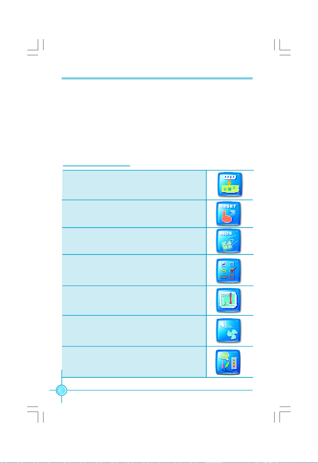
Humanity Technologies
Exclusive Graphics Power
Exclusive power for graphics card for better graphics perfor-
mance and for future upgrade usage.
One Click Resume
Push "reset", return to previous overclock status
immediately, reduce unnecessary troubles
Quick BIOS Update
Easily refresh BIOS after pressing hot key.
Multi-Boot Agent
Press "ESC" under POST interface, select needed boot
equipment in "Boot Menu".
CPU Protection
Automatically cut off power with temperature up to certain
degree, more effectly protects motherboard and CPU.
Smart FAN Commander
Auto fan speed adjustment, save power consumption and
reduce noise pollution.
Smart Audio
Smart hi-fi equipment installation guidance, easy config-
ure 5.1 or 7.1 channel sound effects home theater.
6
Page 14
Chapter 1 Product Introduction
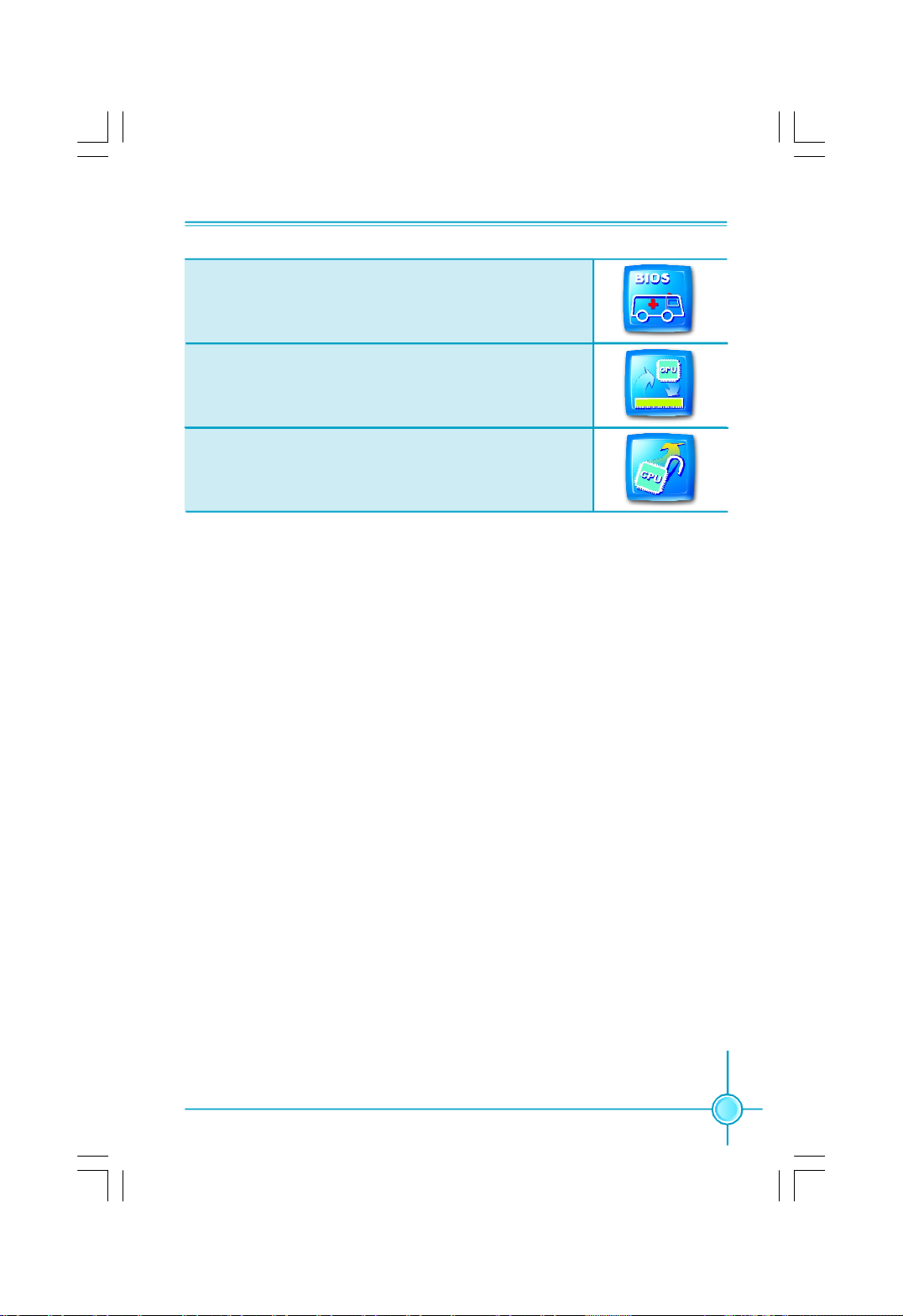
BIOS Rescue
BIOS Boot Block protection. Insert the floppy disk and reboot,
rescue the crashed BIOS.
Super MPT
Base on Intel MPT, accelerates the speed of access from
CPU to memory.
Super Clock Free
Adjustable CPU Multiplier, perform better FSB, more options
for overclocking.
7
Page 15
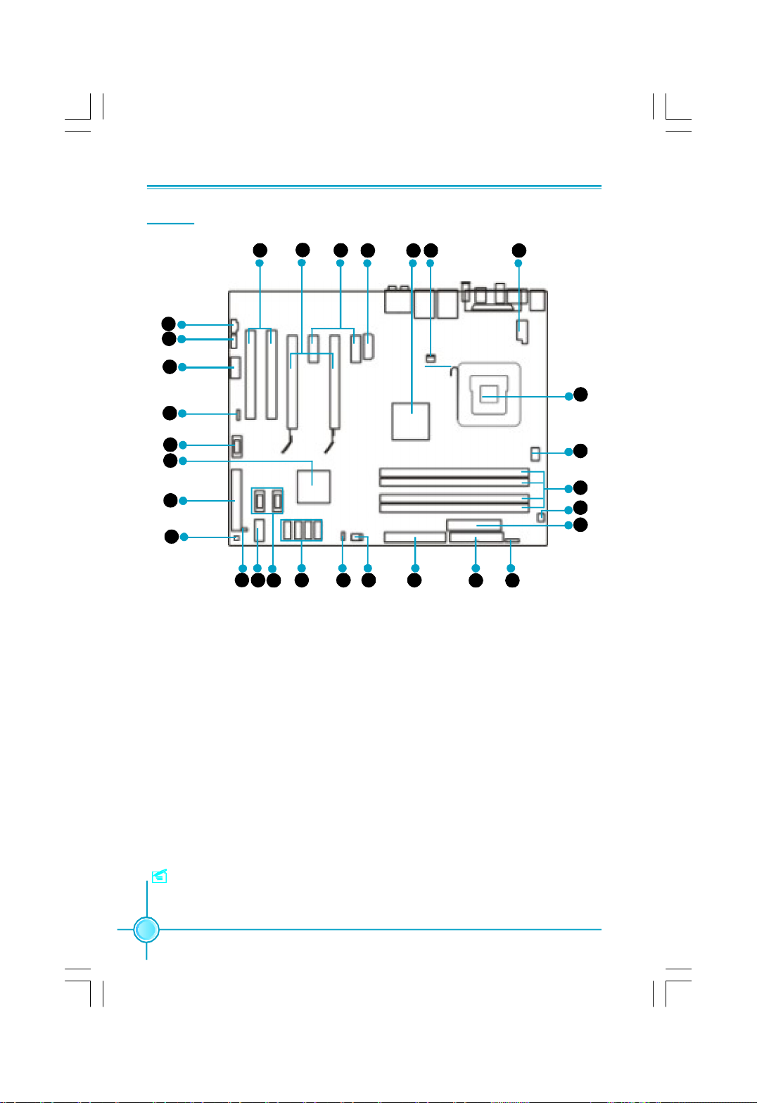
Layout
Chapter 1 Product Introduction
6
7
8
9
10
11
12
13
14
15
16 17
1. 8-pin ATX_12V Power Connector
2. FAN Connector
3. North Bridge: Intel® 975X Chipset
4. PWR3 Connector
5. PCI Express x1 Slots
6. PCI Express x16 Slots
7. PCI Slots
8. CD_IN Connector
9. Front Audio Connector
10. COM1 Connector
11. Speaker Connector(optional)
12. 1394a Connector (optional)
13. South Bridge: Intel® ICH7R Chipset
14. ATA 100/66 IDE Connector: SIDE 1
15. Power Button:SW1(optional)
19 20 21 22
18
34 2 15
29
28
27
26
25
23 24
16. Chassis Intruder Connector
17. Front Panel Connector
18. USB Connectors
19. Serial ATA II Connectors (ICH7R Controlled)
20. Clear CMOS Jumper
21. SYS_FAN Connector
22. ATA 133/100/66 IDE Connector: PIDE
23. FDD Connector
24. IrDA Header (optional)
25. 24-pin ATX Power Connector
26. PWR_FAN Connector
27. DDR2 DIMM Slots
28. CPU_Fan Connector
29. LGA 775 CPU Socket
Note: The above motherboard layout is provided for reference only, please
refer to the physical motherboard.
8
Page 16
Chapter 1 Product Introduction
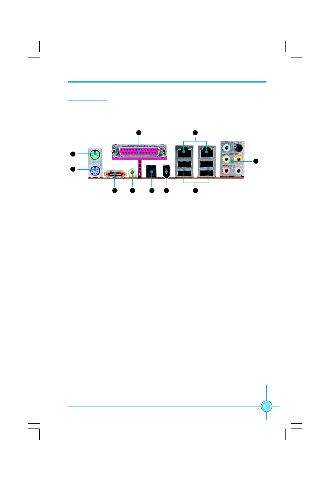
Rear I/O Ports
This motherboard provides the ports as below:
10 9
1
2
3
4 5 6
3
1. PS/2 Mouse Port
This port is used to connect a PS/2 mouse.
2. PS/2 Keyboard Port
This port is used to connect a PS/2 keyboard.
8
7
3. External SATA Port
This port is used to connect an external SATA box or a Serial ATA port multiplier
and enables smart setup and hot-plug function.
4. Coaxial S/PDIF Out Port
This port is used to connect an external audio output device via a coaxial S/PDIF
cable.
5. Optical S/PDIF Out Port
This port is used to connect an external audio output device via a optical S/PDIF
cable.
6. 1394a Port
This port is used to connect a 1394 device.
7. USB2.0 Ports
The four ports are used to connect USB2.0 devices.
9
Page 17
Chapter 1 Product Introduction
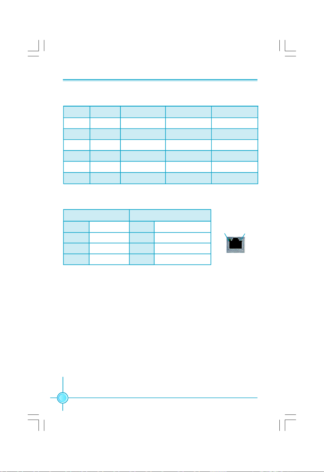
8. Line in, Line out, Microphone, Rear, LEF/CEN, Side Jacks
Port 2-channel 4-channel 6-channel 8-channel
Blue Line In Line In Line In Line In
Green Line Out Front Speaker Out Front Speaker Out Front Speaker Out
Pink Mic In Mic In Mic In Mic In
Orange - - Center/Subwoofer Center/Subwoofer
Black - Rear Speaker Out Rear Speaker Out Rear Speaker Out
Grey - - - Side Speaker Out
9. LAN Ports
Left : Link/Active LED Right: Speed LED
Link/Active
Status Description Status Description
Off No Link Off 10 Mbps Connection
Green Linked Green 100 Mbps Connection
Blinking Data Activity Orange 1 Gbps Connection
LED
10. Parallel Port
The port is used to connect a parallel port device, such as a printer.
Speed
LED
LAN Port
10
Page 18
Chapter 1 Product Introduction
Chapter
This chapter introduces the hardware installation process, in-
cluding the installation of the CPU, memory, power supply,
slots, and pin headers, and the mounting of jumpers. Cau-
tion should be exercised during the installation of these
modules. Please refer to the motherboard layout prior to any
installation and read the contents in this chapter carefully.
This chapter includes the following information:
2
2
v CPU
v Memory
v Power supply
v Other Connectors
v Expansion Slots
v Jumpers
11
Page 19
CPU
Chapter 2 Installation Instructions
This motherboard supports Intel® CoreTM 2 Extreme,Core
TM
2 Duo,Pentium
®
Extreme Edition, Pentium® D, Pentium® 4 processors in an LGA775 package
with a Front Side Bus (FSB) of 1066/800 MHz.
For the detailed CPU support list on this motherboard, please visit the
website: http://www.foxconnchannel.com
Installation of CPU
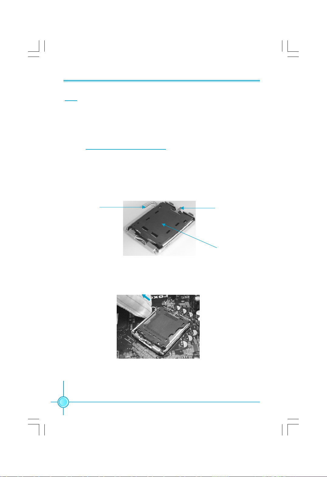
Below is the CPU socket illustration. Follow these procedures to install a CPU.
Load lever
Load plate
Protective cover
1. Use thumb and forefinger to hold the hook of the load lever and pull the lever
down and away from socket to unlock it. Lift the load lever.
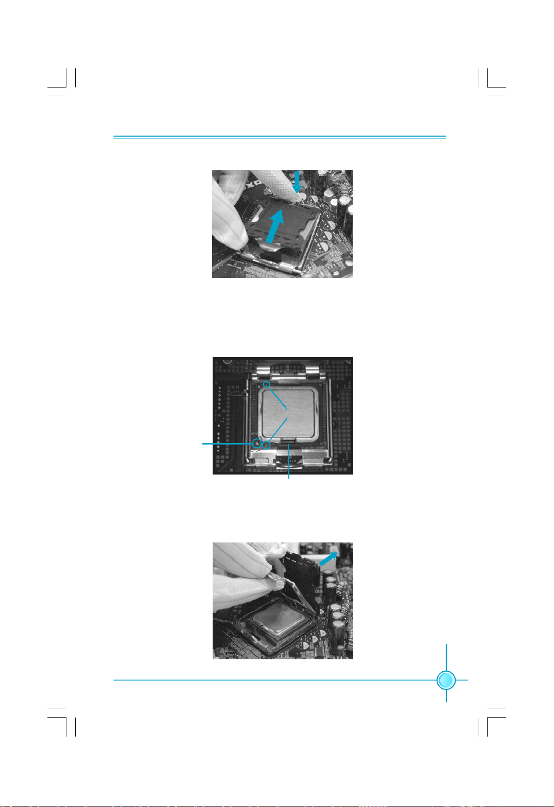
2. Push down the rear tab with your forefinger to bring the front end of the load
plate up slightly. Open the load plate with thumb. Be careful not to touch the
contacts.
12
Page 20
Chapter 2 Installation Instructions
3. Hold CPU with thumb and forefinger. Ensure fingers align to socket cutouts.
Match the CPU triangle marker to Pin 1 position as shown below. The alignment
key also provides the orientation directed function. Lower the CPU straight down
without tilting or sliding the CPU in the socket.
Alignment Key
Pin 1 position
Socket Cutouts
4. After installing the CPU, remove the protective cover from load plate. The
protective cover is used to protect the contacts of the socket. Do not discard the
protective cover. Always replace the socket cover if the CPU is removed from the
socket.
13
Page 21

Chapter 2 Installation Instructions
5. Close the load plate, and slightly push down the tongue side.
6. Lower the lever and lock it to the load plate, then the CPU is locked completely.
14
Note :
Excessive temperatures will severely damage the CPU and
system. Therefore, you should install CPU cooling fan and make
sure that the cooling fan works normally at all times in order to
prevent overheating and damaging to the CPU. Please refer to your
CPU fan user guide to install it properly.
Page 22
Chapter 2 Installation Instructions
Memory
This motherboard includes four 240-pin slots with 1.8V for DDR2. These slots
support dual channel DDR2 memory technology up to 10.7GB/s. You must install
at least one memory bank to ensure normal operation.
Recommended Memory Configurations
The following table list is the recommended memory configurations. Please
install the memory according to the list.
Mode DIMM1 DIMM2 DIMM3 DIMM4
Populated
Single Channel
Populated Populated
Dual Channel
Populated Populated Populated Populated
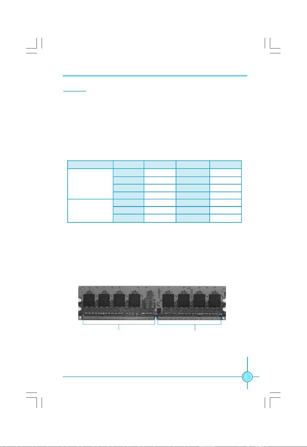
Installation of DDR2 Memory
1.There is only one gap near the center of the DIMM slot, and the memory
module can be fixed in one direction only. Unlock a DIMM slot by pressing the
module clips outward.
2.Align the memory module to the DIMM slot, and insert the module vertically
into the DIMM slot.
Populated
Populated
Populated
Populated Populated
128 Pins
3.The plastic clips at both sides of the DIMM slot will lock automatically.
112 Pins
15
Page 23

Chapter 2 Installation Instructions
Warning :
Be sure to unplug the AC power supply before adding or removing
expansion cards or other system peripherals, especially the
memory devices, otherwise your motherboard or the system
memory might be seriously damaged.
For the detailed memory support list on this motherboard, please visit the
website: http://www.foxconnchannel.com
16
Page 24
Chapter 2 Installation Instructions
Power Supply
This motherboard uses an ATX power supply. In order to avoid damaging any
devices, make sure that they have been installed properly prior to connecting
the power supply.
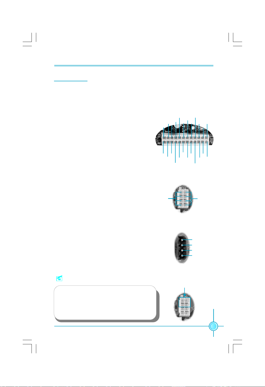
24-pin ATX power connector: PWR1
PWR1 is the ATX power supply connector. Make
sure that the power supply cable and pins are
properly aligned with the connector on the
motherboard. Firmly plug the power supply cable
into the connector and make sure it is secure.
24-pin ATX Power Connector
RSVD
GND
+5V
GND
+5V
GND
24
12
+12V
+
PWROK
5V_AUX
GND
+5V
+3.3V
+12V
PS-ON
GND
GND+5V
+3.3V
-12V
13
1
+3.3V
GND
+3.3V
GND
+5V
8-pin ATX_12 V Power Connector: PWR2
The 8-pin ATX 12V power supply connects to
PWR2 and provides power to the CPU.
Exclusive Graphics Power Connector: PWR3
This connector is a auxiliary power for graphics
card. Exclusive power for graphics card is for bet-
ter graphics performance and for future upgrade
usage.
Note:
We strongly recommend that you use 8-pin ATX
12V power supply. If you want to use 4-pin
power supply, connect the 4-pin power con-
nector as shown.
8-pin ATX_12 V Power Connector
5
12V
8
Exclusive Graphics Power Connector
4
1
Connect a 4-pin
power plug here
5
8
1
GND
4
+5V
GND
GND
+12V
1
4
17
Page 25

Chapter 2 Installation Instructions
Note:
We strongly recommend that you use 350 W power supply or above.
If you use the Dual PCI Express Graphics Cards, we recommend
that you use 500W power supply or above.
Other Connectors
This motherboard includes connectors for FDD devices, IDE devices, Serial ATA
devices, USB devices, IR module, and others.
FDD Connector: FLOPPY
This motherboard includes a standard FDD connector, supporting 360K, 720K,
1.2M, 1.44M, and 2.88M FDDs.
IDE Connectors: PIDE, SIDE1(optional)
The PIDE connector supports Ultra ATA 133/100/66 IDE hard disk drives. The
SIDE1 connector supports Ultra ATA 100/66 IDE hard disk drives. The PIDE,
SIDE1 also support RAID function.
Connect the cable’s blue connector to the IDE connector, then connect the gray
connector to the slave device (hard disk drive) and the black connector to the
Ultra ATA master device. If you install two hard disks, you must configure the
second drive as a slave device by setting its jumper accordingly. Refer to the hard
disk documentation for the jumper settings.
Attention:
Ribbon cables are directional, therefore, make sure to always
connect with the cable on the same side as pin 1 of the PIDE/RIDE
or FLOPPY connector on the motherboard.
18
Page 26
Chapter 2 Installation Instructions
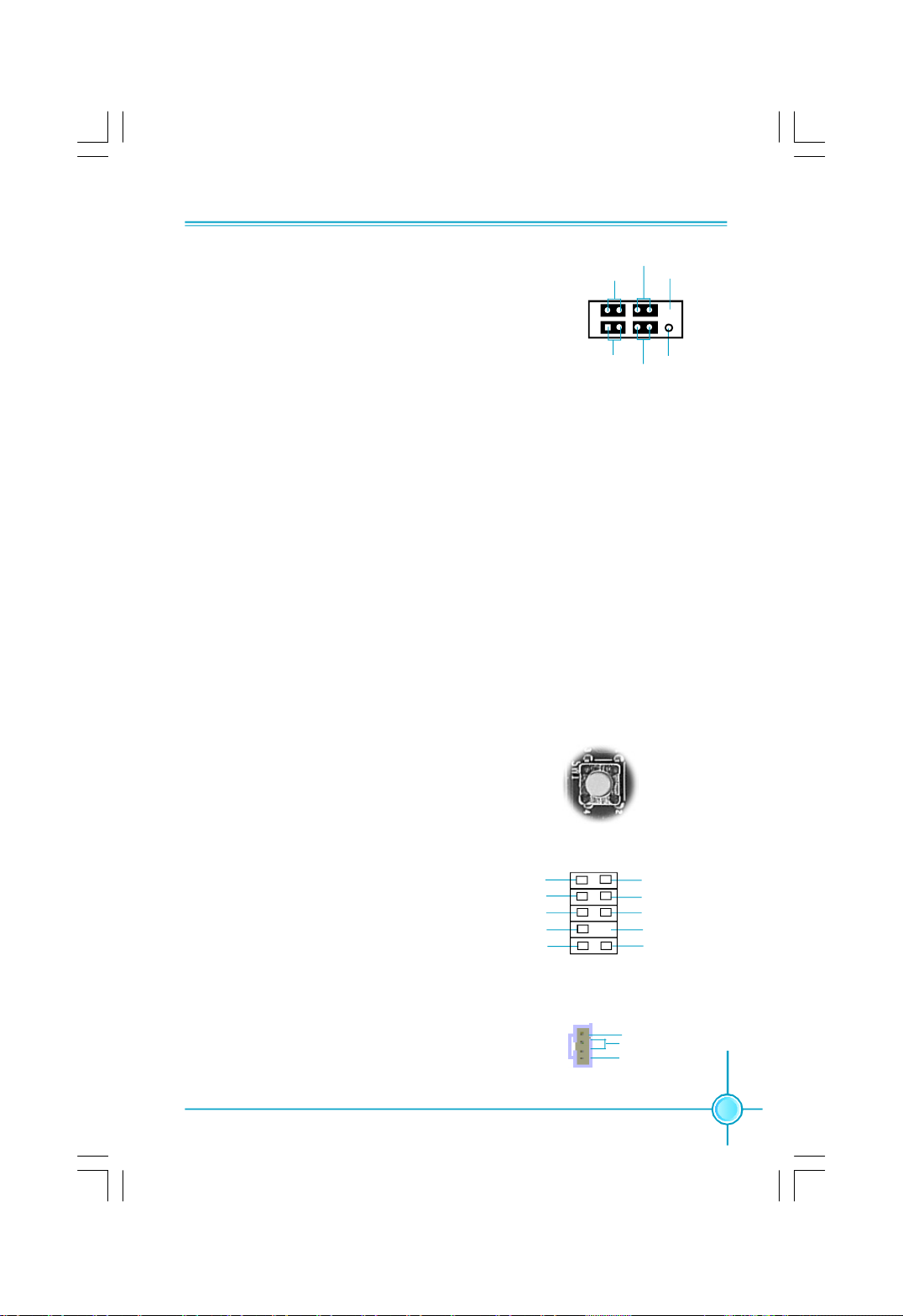
Front Panel Connector: FP1
This motherboard includes one connector for con-
PWRLED
+ -
PWRSW
Empty
necting the front panel switch and LED indicators.
1
+ -
NCHD-LED
RESET
HDD LED Connector (HD-LED)
FP1
The connector connects to the case’s HDD indicator LED indicating the activity
status of hard disks.
Reset Switch (RESET)
Attach the connector to the Reset switch on the front panel of the case; the
system will restart when the switch is pressed.
Power LED Connector (PWRLED)
Attach the connector to the power LED on the front panel of the case. The Power
LED indicates the system’s status. When the system is in S0 status, the LED is
on. When the system is in S1 status, the LED is blink; When the system is in S3,
S4, S5 status, the LED is off.
Power Switch Connector (PWRSW)
Attach the connector to the power button of the case. Pushing this switch allows
the system to be turned on and off rather than using the power supply button.
Power Button(SW1)
Using this button allows the system to
be turned on and off .
Audio Connector: F_AUDIO1
The audio connector supports HD audio standard. It provides two kinds of
audio output choices: the Front Audio,
SENSE_SEND
the Rear Audio. Front Audio supports
re-tasking function.
Audio Connectors: CD_IN
CD_IN is Sony standard CD audio connectors,
it can be connected to a CD-ROM drive through
a CD audio cable.
PORT1_L
PORT1_R
PORT2_R
PORT2_L
SW1
1
F_AUDIO1
1
CD_IN
AUD_GND
PRESENCE_J
SENSE1_RETURN
Empty
SENSE2_RETURN
CD_L
GND
CD_R
19
Page 27
Chapter 2 Installation Instructions
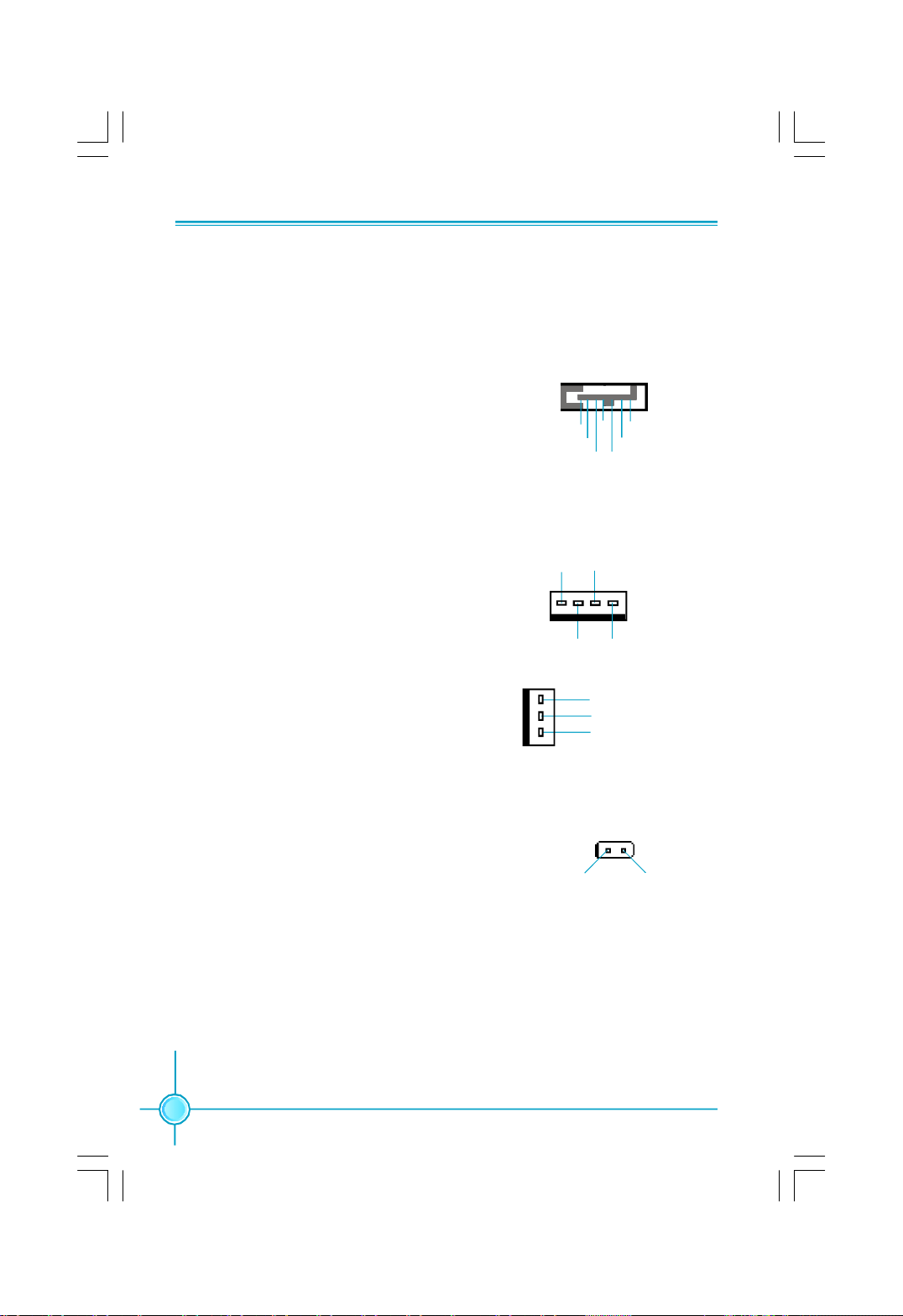
Serial ATA II Connectors: SATA_1, SATA_2,
SATA_3, SATA_4
The Serial ATA II connector is used to connect
the Serial ATA II device to the motherboard. These
connectors support the thin Serial ATA II cables
for primary storage devices. The current Serial
ATA II interface allows up to 300MB/s data trans-
fer rate.
SATA_1/SATA_2/SATA_3/SATA_4 supports a
RAID 0, RAID 1, RAID 5, RAID 0+1 configuration
with the Intel ICH7R RAID controller.
1
GND
TX+
SATA_1/2/3/4
GND GND
RX+
RX-TX-
Fan Connectors: CPU_FAN, FAN1, SYS_FAN1,
PWR_FAN
The fan speed can be detected and viewed in
“PC Health Status” section of the CMOS Setup.
These fans will be automatically turned off after
the system enters S3, S4 and S5 mode.
Chassis Intruder Connector: INTR
The connector connects to the chassis security switch on the case. The system can detect
the chassis intrusion through the status of this
connector. If the connector has been closed
once, the system will send a message. To utilize this function, set “Case Open Warning” to
“Enabled” in the “Power Management Setup”
section of the CMOS Setup. Save and exit, then
boot the operating system once to make sure
this function takes effect.
GROUND
1
1
SENSE
POWERCONTROL
GROUND
+12V
SENSE
1 INTRUDERJ 2 GND
INTR
CPU_FAN
FAN1
SYS_FAN1
PWR_FAN
20
Page 28
Chapter 2 Installation Instructions
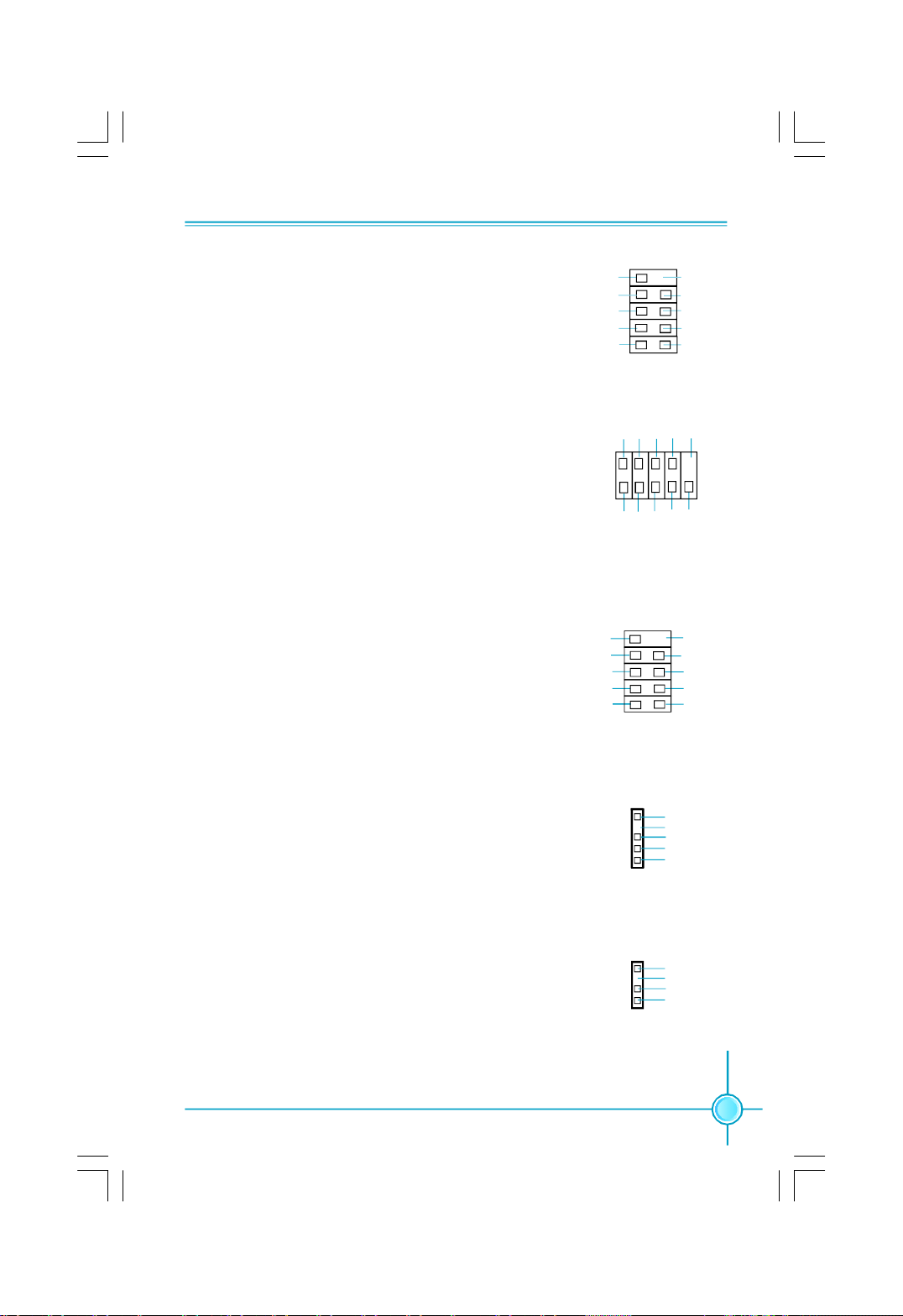
USB Headers: F_USB1, F_USB2
Besides four USB ports on the rear panel, the series of
motherboards also have two 10-pin headers on board
which may connect to front panel USB cable (optional)
to provide additional four USB ports.
Additional COM Connector: COM1
This motherboard provides an additional serial COM
header for your machine.
Connect one side of a switching cable to the header,
then attach the serial COM device to the other side of
the cable.
1394 Connector: F_1394 (optional)
The 1394 expansion cable can be connected to either
the front (provided that the front panel of your chassis
is equipped with the appropriate interface) or real
panel of the chassis.
NC
GND
D+
D-
5V_DUAL
F_USB 1/2
2
1
GND
+12V
TPB -
GND
TPA -
DTR#
DSR# SIN
GND RLSD RI#
SOUT
COM1
F_1394
CTS#
910
12
1
Empty
RTS#
TPB +
TPA +
Empty
GND
D+
D-
5V_DUAL
10
9
Empty
+12V
GND
IrDA Connector: IR(optional)
This header supports wireless transmitting and receiv-
ing device. Before using this function, configure the
settings of IR Mode from the “ Integrated Peripherals”
section of the CMOS Setup.
Speaker Connector: SPEAKER(optional)
The speaker connector is used to connect speaker of
the chassis.
1
IR
1
SPEAKER
+5V
Empty
IRRX
GND
IRTX
SPKJ
Empty
NC
SPKJ
21
Page 29

Chapter 2 Installation Instructions
Expansion Slots
This motherboard includes two 32-bit master PCI bus slots, two PCI Express
x 1 slots and two PCI Express x 16 slots.
PCI Slots
The expansion cards can be installed in the two PCI slots. PCI slots support
cards such as a LAN card, USB card, SCSI card and other cards that comply
with PCI specifications.
PCI Express x1 Slots
This motherboard has two PCI Express x1 slots that designed to accommodate
less bandwidth-intensive cards, such as a modem or LAN card.
PCI Express x16 Slots
This motherboard has two PCI Express x16 slots that reserved for graphics or
video cards. The difference in bandwidth between the x16 and x1 slots is no-
table to be sure, with the x16 slot pushing 4GB/sec (8GB/sec concurrent) of
bandwidth, and the PCI Express x1 slot offering 250MB/sec.
This motherboard design enables the support of dual PCI-Express graphics
cards technology such as “ATI’s CrossFireTM” and multiple display.
For the detailed PCI Express x16 graphics cards support list on this
motherboard, please visit the website: http://www.foxconnchannel.com
22
Page 30
Chapter 2 Installation Instructions
Jumpers
The users can change the jumper settings on this motherboard if needed. This
section explains how to use the various functions of this motherboard by chang-
ing the jumper settings. Users should read the following content carefully prior to
modifying any jumper settings.
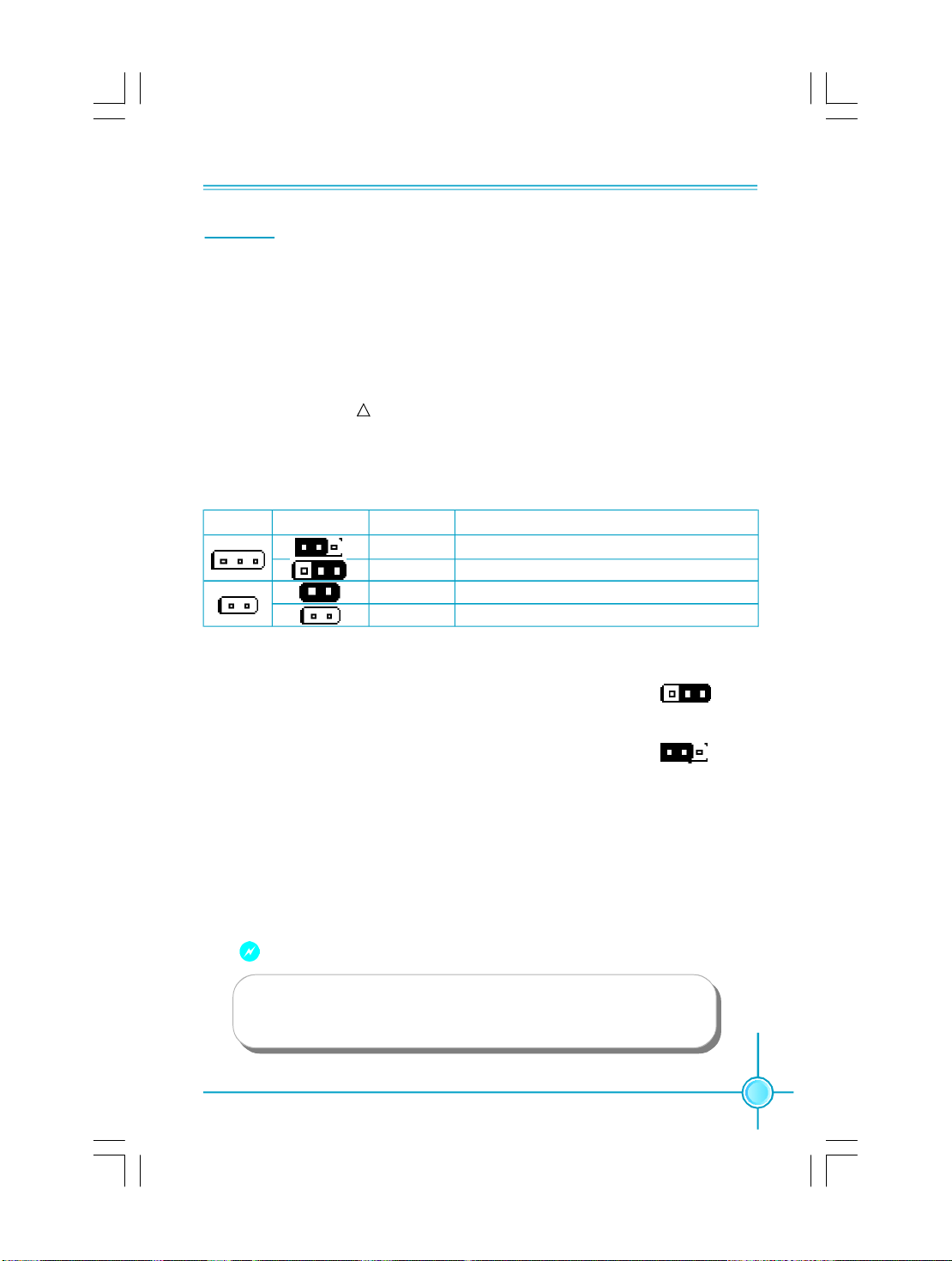
Description of Jumpers
1. For the jumpers on this motherboard, pin 1 can be identified by the silk-
screen printed “ ” next to it. However, in this manual, pin 1 is simply
labeled as “1”.
2. The following table provides some explanation of the jumper pin settings.
User should refer to this when adjusting jumper settings.
Jumper Diagram Definition Description
1
1
1
1
1
1
Clear CMOS Jumper: CLR_CMOS
The motherboard uses the CMOS RAM to store all
the set parameters. The CMOS can be cleared by
removing the CMOS jumper.
How to clear CMOS?
1. Turn off the AC power supply and connect pins 1
and 2 together using the jumper cap.
2. Return the jumper setting to normal (pins 2 and 3
together with the jumper cap).
3. Turn the AC power supply back on.
1-2 Set pin1 and pin2 closed
2-3 Set pin2 and pin3 closed
Closed Set the pin closed
Open Set the pin opened
NORMAL
(Default)
CLEAR
CLR_CMOS
1 3 2
1 3 2
Warning:
1. Disconnect the power cable before adjusting the jumper settings.
2. Do not clear the CMOS while the system is turned on.
23
Page 31

Chapter 3 BIOS Description
Chapter
24
3
3
This chapter tells how to change system settings through the
BIOS Setup menus. Detailed descriptions of the BIOS param-
eters are also provided.
You have to run the Setup Program when the following cases
occur:
1.An error message appears on the screen during the system
POST process.
2.You want to change the default CMOS settings.
This chapter includes the following information:
v Enter BIOS Setup
v Main Menu
v Standard CMOS Features
v FOX Central Control Unit
v Advanced BIOS Features
v Advanced Chipset Features
v Integrated Peripherals
v Power Management Setup
v PnP/PCI Configurations
v PC Health Status
v Load Fail-Safe Defaults
v Load Optimized Defaults
v Set Supervisor/User Password
v Save & Exit Setup
v Exit Without Saving
Page 32
Chapter 3 BIOS Description
Enter BIOS Setup
The BIOS is the communication bridge between hardware and software,
correctly setting up the BIOS parameters is critical to maintain optimal system
performance. Power on the computer, when the following message briefly
appears at the bottom of the screen during the POST (Power On Self Test),
press <Del> key to enter the Award BIOS CMOS Setup Utility.
Press TAB to show POST Screen, DEL to enter SETUP, ESC to enter Boot Menu.
Note:
We do not suggest that you change the default parameters in the
BIOS Setup, and we shall not be responsible for any damage that
result from any changes that you make.
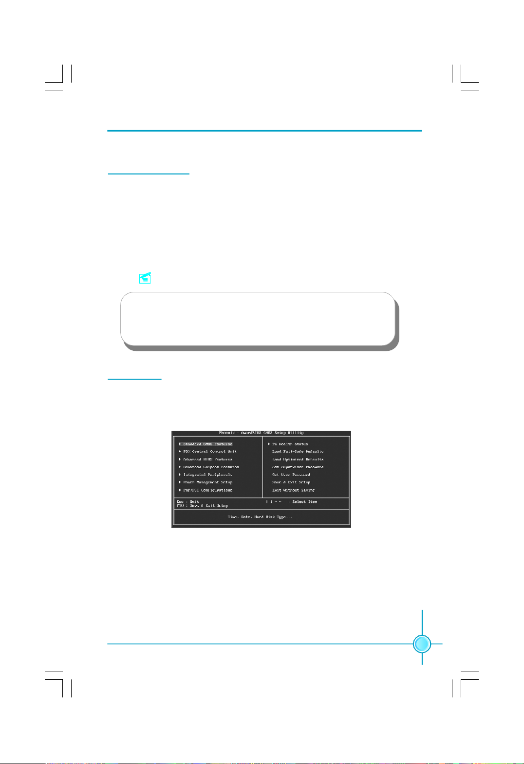
Main Menu
The main menu allows you to select from the list of setup functions and two exit
choices. Use the arrow keys to select among the items and press <Enter> to
accept or go to the sub-menu.
Main Menu
The items in the main menu are explained as below:
Standard CMOS Features
The basic system configuration can be set up through this menu.
FOX Central Control Unit
The special features can be set up through this menu.
25
Page 33

Chapter 3 BIOS Description
Advanced BIOS Features
The advanced system features can be set up through this menu.
Advanced Chipset Features
The values for the chipset can be changed through this menu, and the sys-
tem performance can be optimized.
Integrated Peripherals
All onboard peripherals can be set up through this menu.
Power Management Setup
All the items of Green function features can be set up through this menu.
PnP/PCI Configurations
The system’s PnP/PCI settings and parameters can be modified through
this menu.
PC Health Status
This will display the current status of your PC.
Load Fail-Safe Defaults
The default BIOS settings can be loaded through this menu.
Load Optimized Defaults
The optimal performance settings can be loaded through this menu,
however, the stable default values may be affected.
Set Supervisor Password
The supervisor password can be set up through this menu.
Set User Password
The user password can be set up through this menu.
Save & Exit Setup
Save CMOS value settings to CMOS and exit setup.
Exit Without Saving
Abandon all CMOS value changes and exit setup.
26
Page 34
Chapter 3 BIOS Description
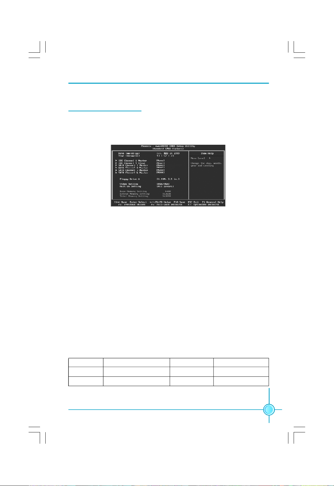
Standard CMOS Features
This sub-menu is used to set up the standard CMOS features, such as the date,
time, HDD model and so on. Use the arrow keys select the item to set up, and
then use the <PgUp> or <PgDn> keys to choose the setting values.
Standard CMOS Features Menu
Date
This option allows you to set the desired date (usually as the current day) with
the <day><month><date><year> format.
Day—weekday from Sun. to Sat., defined by BIOS (read-only).
Month—month from Jan. to Dec..
Date—date from 1st to 31st, can be changed using the keyboard.
Year—year, set up by users.
Time
This option allows you to set up the desired time (usually as the current time)
with <hour><minute><second> format.
IDE Channel 1 Master/Slave, SATA Channel 1/2/3/4 Master
These categories identify the HDD types of 1 IDE channel and 4 SATA channels
installed in the computer system. System can auto-detect the hard disk when
booting up, select these items and press<Enter>, the information directly display.
Cylinder number of cylinders Head number of heads
Precomp write pre-compensationLanding Zone landing zone
Sector number of sectors
27
Page 35

Chapter 3 BIOS Description
Award (Phoenix) BIOS can support 3 HDD modes: CHS, LBA and Large or Auto mode.
CHS For HDD<528MB
LBA For HDD>528MB & supporting LBA (Logical Block Addressing)
Large For HDD>528MB but not supporting LBA
Auto Recommended mode
Floppy Drive A
This option allows you to select the kind of FDD to be installed, including “None”,
[360K, 5.25 in], [1.2M, 5.25 in], [720K, 3.5 in], [1.44M, 3.5 in] and [2.88 M, 3.5 in].
Halt On
This category determines whether or not the computer will stop if an error is
detected during powering up.
All Errors Whenever the BIOS detects a nonfatal error, the system
will stop and you will be prompted.
No Errors The system boot will not stop for any errors that may
be detected.
All, But Keyboard The system boot will not stop for a keyboard error; but
it will stop for all other errors.
All, But Diskette The system boot will not stop for a diskette error; but
it will stop for all other errors.
All, But Disk/Key The system boot will not stop for a keyboard or disk
error, but it will stop for all other errors.
Memory
This is a Display-Only Category, determined by POST (Power On Self Test) of
the BIOS.
Base Memory The BIOS POST will determine the amount of base (or
conventional) memory installed in the system.
Extended Memory The BIOS determines how much extended memory
is present during the POST.
Total Memory Total memory of the system.
28
Page 36
Chapter 3 BIOS Description
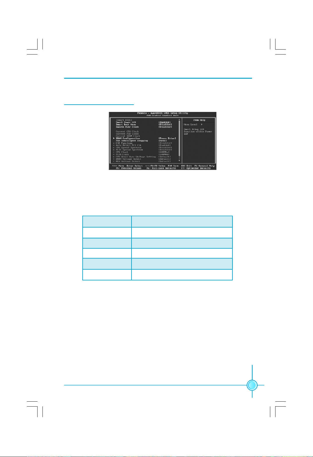
FOX Central Control Unit
FOX Central Control Unit Menu
v[Smart BIOS]
Smart Power LED
Smart debug LED function within power LED. Enable this function, the power
LED status can show the system status of POST process.
System Status Power LED Status
Normal on
No CPU Fan blinking once (blinking 0.5 sec., off 0.5 sec.)
No Display blinking once (blinking 2 sec., off 2 sec.)
No Memory blinking twice
Post Error Message blinking thrice
Smart Boot Menu
Smart boot menu with a timer to let user to control boot device easily.
Smooth Over Clock
To open smooth over clock function can let over clocking to be more stable.
vCurrent CPU/FSB/DRAM Clock
This option is used to show current CPU/FSB/DRAM clock value.
vDRAM Configuration
Press Enter to set the items of DRAM Configuration.
29
Page 37

Chapter 3 BIOS Description
vFOX Intelligent Stepping
User can select different overclocking option by this item. The available setting values are: Manual, Auto, Power gaming, Data Mining, Office, Energy
Saving.
vC1E Function(optional)
This option is used to enabled or disabled the C1E(Enhanced Halt State)
function.
vAuto Detect PCI Clk
This option is used to set whether the clock of an unused PCI slot will be
disabled to reduce electromagnetic interference. The setting values are
Disabled and Enabled.
vSpread Spectrum
If you enable spread spectrum, it can significantly reduce the EMI (ElectroMagnetic Interference) generated by the system. The setting values are
Disabled and Enabled.
vCPU Clock
This option is used to set the CPU clock.
vPCIE Clock
This option is used to set the PCI Express clock.
vCPU Vcore Over Voltage Setting
This option is used to set CPU Vcore over voltage.
vDRAM Voltage Select
This option is used to set DRAM voltage.
vMCH Voltage Select
This option is used to set the memory controller hub (MCH) voltage.
vCPU Termination Voltage
This option is used to set the CPU termination voltage.
30
Page 38

Chapter 3 BIOS Description
DRAM Configuration Menu
vDRAM Timing Selectable
This item determines DRAM clock/ timing using SPD or manual configuration.
The available setting values are: By SPD and Manual.
vCAS Latency Time
This item determines CAS Latency. The available setting values are: 3, 4, 5, 6
and Auto.
vDRAM RAS# to CAS# Delay
This item allows you to select a delay time between the CAS and RAS strobe
signals. The available setting values are: 6, 5, 4, 3, 2, and Auto.
vDRAM RAS# Precharge
This item allows you to select the DRAM RAS# precharge time. The available
setting values are: 6, 5, 4, 3, 2, and Auto.
vPrecharge delay(tRAS)
This item allows you to set the precharge delay time. The available setting
values are: Auto, 4 - 15.
vMemlock index value (Mhz)
This item allows you to set memory clock index value.
31
Page 39
Chapter 3 BIOS Description
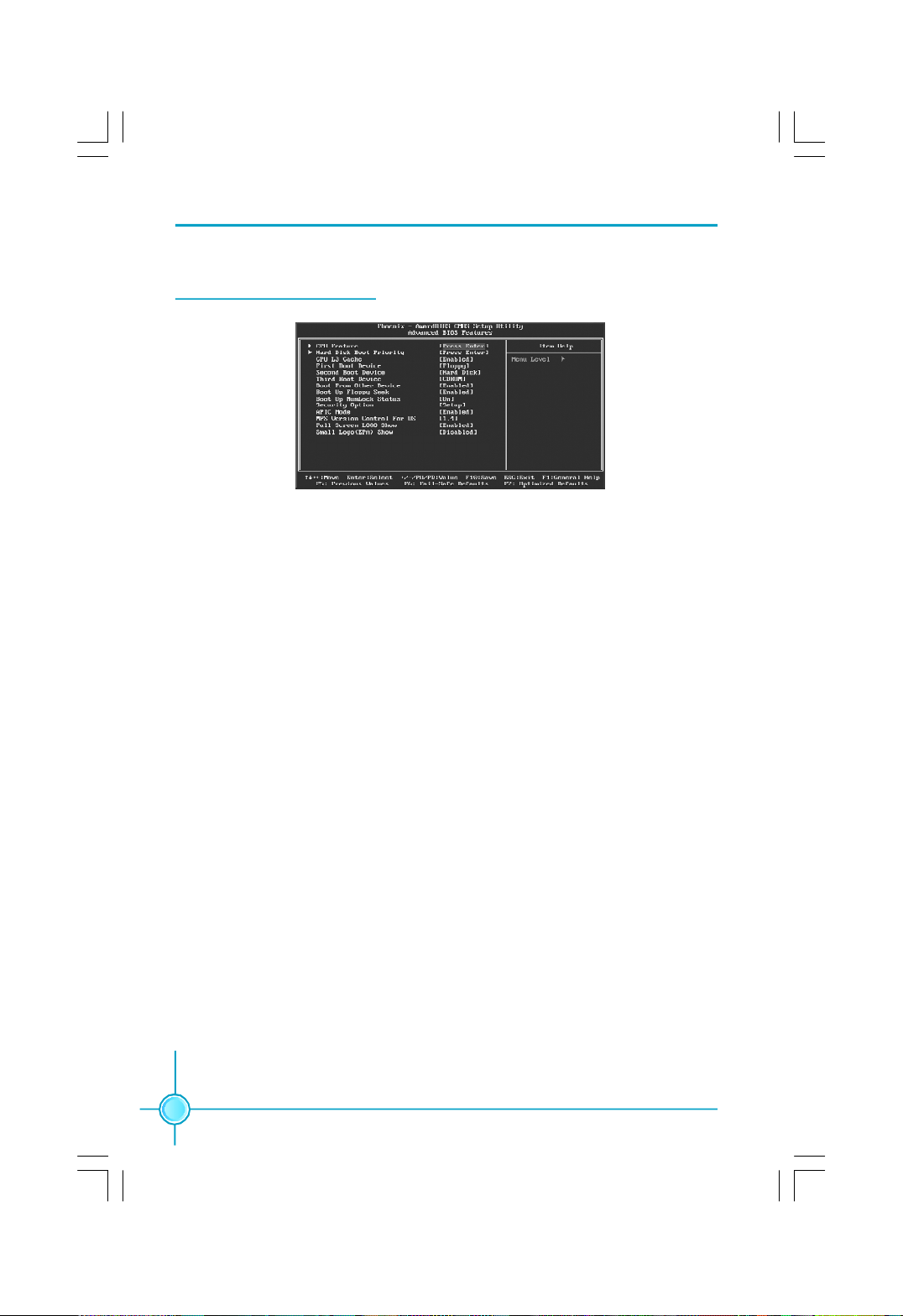
Advanced BIOS Features
Advanced BIOS Features Menu
vCPU Feature
Press enter to set the items of CPU feature.
vHard Disk Boot Priority
This option is used to select the priority for HDD startup. After pressing
<Enter>, you can select the HDD using the <PageUp>/<PageDn> or Up/
Down arrow keys, and change the HDD priority using <+> or <->; you can
exit this menu by pressing <Esc>.
vCPU L3 Cache (optional)
This option is used to enable or disable the CPU L3 cache. The available
setting values are: Disabled and Enabled.
vFirst/Second/Third Boot Device
This option allows you to set the boot device’s sequence.
vBoot From Other Device
With this function set to enable, the system will boot from some other devices if the first/second/third boot devices failed. The setting values are: Disabled and Enabled.
vBoot Up Floppy Seek
This option controls whether the BIOS checks for a floppy drive while booting
up. If it cannot detect one (either due to improper configuration or physical
unavailability), it will appear an error message. The available setting values
are: Disabled and Enabled.
32
Page 40

Chapter 3 BIOS Description
vBoot Up NumLock Status
This item defines if the keyboard Num Lock key is active when your system is
started. The available setting values are: On and Off.
vSecurity Option
When it is set to “Setup”, a password is required to enter the CMOS Setup
screen; When it is set to “System”, a password is required not only to enter
CMOS Setup, but also to start up your PC.
vAPIC Mode
This option is used to enable or disable APIC function.
vMPS Version Control For OS
This option is used to set up the version of MPS Table used in NT4.0 OS.
vFull Screen LOGO Show
This option allows you to enable or disable the full screen logo. The available
setting values are: Disabled and Enabled.
vSmall Logo (EPA) Show
This option allows you to enable or disable the EPA logo. The available setting
values are: Disabled and Enabled.
33
Page 41
Chapter 3 BIOS Description
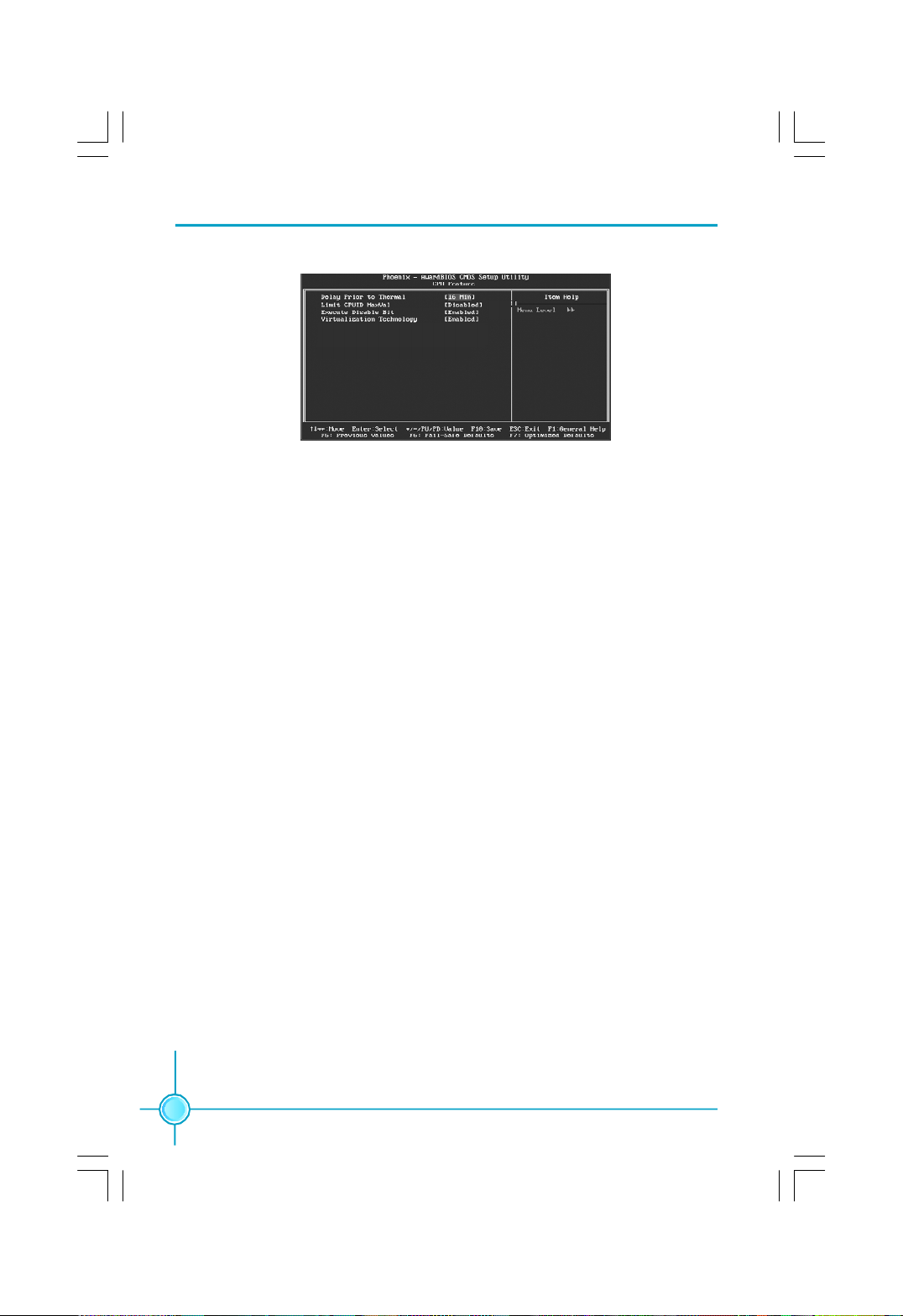
CPU Feature Menu
v Delay Prior to Thermal
This option is used to set the delay time before the CPU enters auto thermal
mode. The setting values are: 4 Min, 8 Min, 16 Min, 32 Min.
vLimit CPUID MaxVal
The option is used to set limit CPUID MaxVal. The available setting values are:
Disabled and Enabled. Set Limit CPUID MaxVal to 3, should be "Disabled" for
WinXP.
vExecute Disable Bit (optional)
The option is used to enable or disable execute disable bit.
vVirtualization Technology (optional)
When enabled, a VMM can utilize the additional hardware capabilities
provided by vendor pool technology.
34
Page 42
Chapter 3 BIOS Description
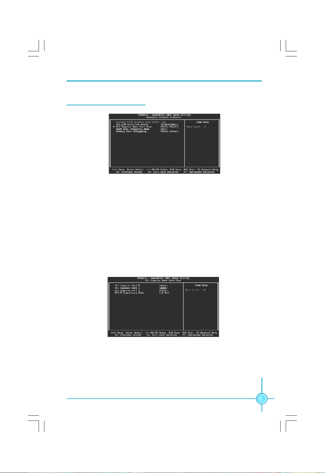
Advanced Chipset Features
Advanced Chipset Features Menu
vCurrent PCIE Graphic Link Width
This option is used to show PCIE graphic link width.
vSLP_S4# Assertion Width
This option is used to set SLP_S4# assertion width.
vPCI Express Root Port Func
Press <Enter> to enter PCI Express Root Port Func sub-menu.
vDRAM Data Integrity Mode
This option is used to set DRAM data integrity mode.
PCI Express Boot Port Func Menu
vPCI Express Port 2/3
This option is used to enable or disable PCI Express port 2/3.
vPCI-E Compliancy Mode
This option is used to select PCI-E compliancy mode.
35
Page 43
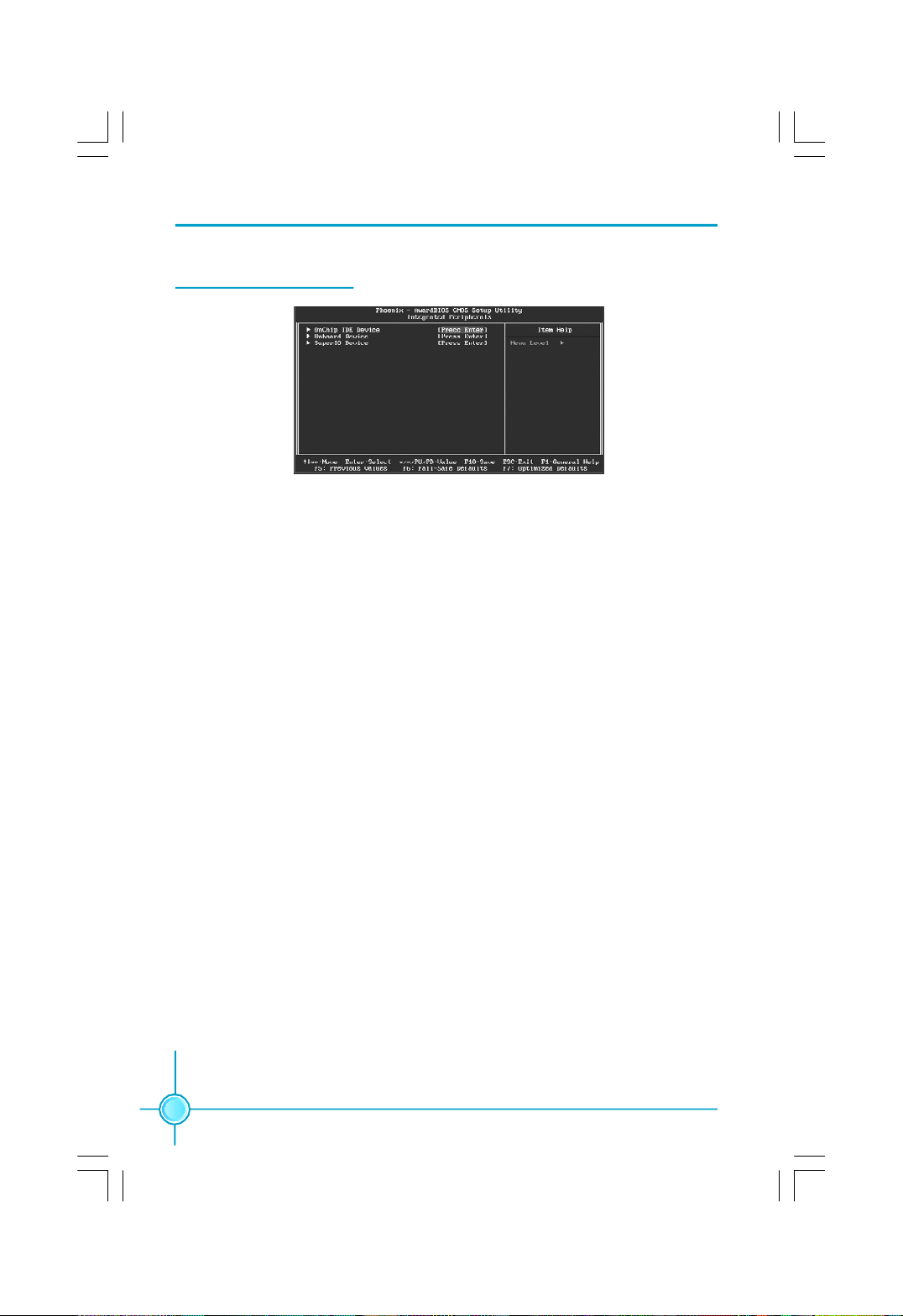
Integrated Peripherals
Integrated Peripherals Menu
vOnChip IDE Device
Press enter to set onchip IDE device.
vOnboard Device
Press enter to set onboard device.
vSuperIO Device
Press enter to set onboard SuperIO device.
Chapter 3 BIOS Description
36
Page 44

Chapter 3 BIOS Description
OnChip IDE Device Menu
vDelay For HDD (Secs)
You can select a delay from 1 to 15 seconds in the cold boot process.
vIDE HDD Block Mode
This option is used to set whether the IDE HDD block mode is allowed.
vIDE DMA transfer access
This option is used to set the IDE transfer access—with it set to Enabled, the
IDE Transfer Access uses the DMA mode; with it set to Disabled, the IDE
Transfer Access uses the PIO mode.
vOn-Chip Primary PCI IDE
Use this item to enable or disable the Primary/Secondary PCI IDE channel
that is integrated on the motherboard.
vSATA Mode
This option is used to set the Serial ATA Mode. The available setting values
are: IDE, RAID, AHCI.
vOn-Chip Serial ATA
This option is used to set the On-chip Serial ATA function.
vSATA PORT Speed Settings
This option is used to set SATA port speed settings.
vPATA IDE Mode
When On-Chip Serial ATA set as “Combined Mode”, this option will be modified.
It is used to set the PATA IDE Mode. The available setting values are: Primary,
Secondary.
vSATA Port
This option is used to set the Serial ATA Port.
37
Page 45
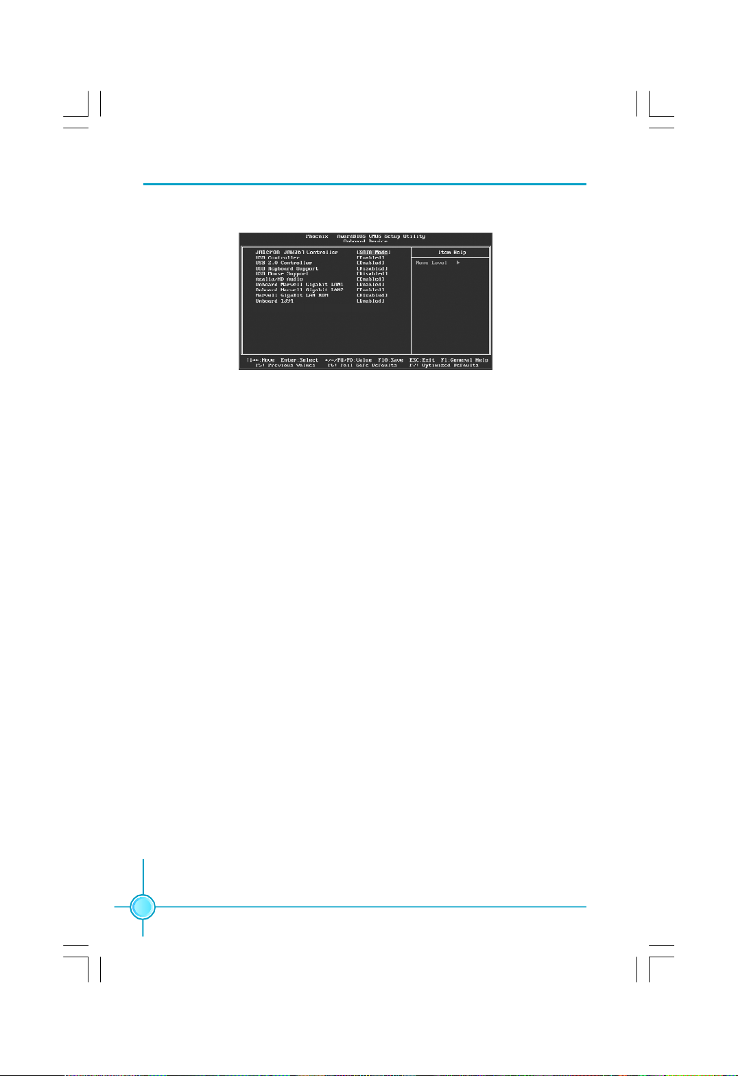
Chapter 3 BIOS Description
Onboard Device Menu
vJMicron JMB361 Controller
This option is used to enable or disable JMicron JMB361Controller
vUSB Controller
This option is used to set whether the USB Controller is enabled. The
available setting values are: Disabled and Enabled.
vUSB 2.0 Controller
This option is used to set whether the USB 2.0 Controller is enabled.
vUSB Keyboard Support
This option is used to set whether the USB keyboard controller is enabled in a
legacy operating system (such as DOS).
vUSB Mouse Support
This option is used to set whether the USB mouse controller is enabled in a
legacy operating system (such as DOS).
vAzalia/HD Audio
This option is used to set whether onboard Azalia/HD Audio is enabled.
vOnboard Marvell Gigabit LAN1/2
This option is used to enable or disable onboard Marvell Gigabit LAN 1/2.
vMarvell Gigabit LAN ROM
This option is used to enable or disable onboard Marvell Gigabit LAN ROM.
vOnboard 1394
This option is used to set whether 1394 function is enabled.
38
Page 46
Chapter 3 BIOS Description
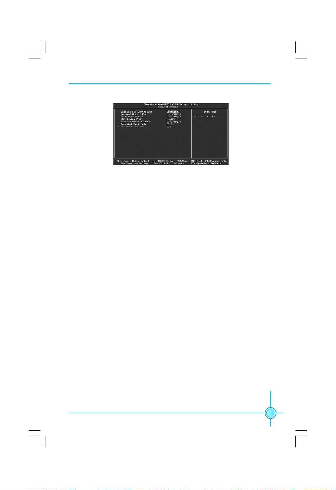
SuperIO Device Menu
vOnboard FDC Controller
This option is used to set whether the Onboard FDC Controller is enabled.
The available setting values are: Disabled and Enabled.
vOnboard Serial Port1/2
This option is used to assign the I/O address and interrupt request (IRQ) for
the onboard serial port 1/2.
Note: Do not try to set the same values for serial ports 1 and 2.
vUART Mode Select
Use this option to select the UART mode. Setting values include Normal,
IrDA, and ASKIR. The setting value is determined by the infrared module in
stalled on the board.
vUR2 Duplex Mode
This option is available when UART 2 mode is set to either ASKIR or IrDA. This
item enables you to determine the infrared function of the onboard infrared chip.
vOnboard Parallel Port
This option allows you to determine onboard parallel port controller I/O address and interrupt request (IRQ). The setting values are: Disabled, 378/IRQ7,
278/IRQ5 and 3BC/IRQ7.
vParallel Port Mode
Select an address and corresponding interrupt for the onboard parallel port.
The setting values are: SPP, EPP, ECP, ECP+EPP.
vECP Mode Use DMA
When the Parallel Port Mode is set to ECP or ECP+ EPP, this option is used to
select the channel for the ECP mode. The setting values are: 1 and 3.
39
Page 47
Chapter 3 BIOS Description
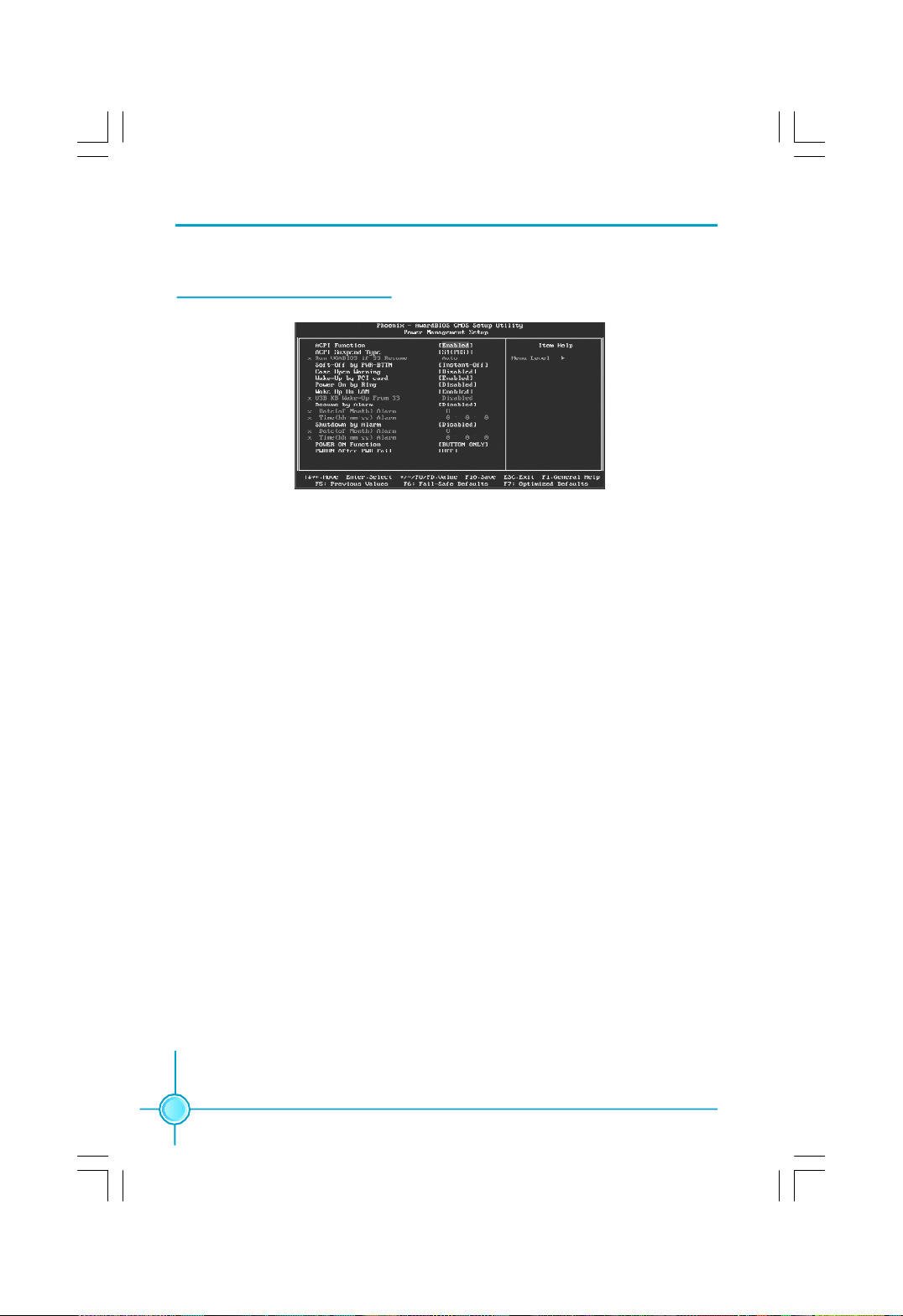
Power Management Setup
Power Management Setup Menu
vACPI function
ACPI stands for “Advanced Configuration and Power Interface”. ACPI is a
standard that defines power and configuration management interfaces between an operating system and the BIOS. In other words, it is a standard that
describes how computer components work together to manage system
hardware. In order to use this function the ACPI specification must be supported by the OS (for example, Windows2000 or WindowsXP). The available
setting values are: Enabled and Disabled.
v ACPI Suspend Type
This option is used to set the energy saving mode of the ACPI function.
When you select “S1 (POS)” mode, the power will not shut off and the
supply status will remain as it is, in S1 mode the computer can be resumed
at any time. When you select “S3 (STR)” mode, the power will be cut off after
a delay period. The status of the computer before it enters STR will be saved
in memory, and the computer can quickly return to previous status when the
STR function wakes. When you select “S1 & S3” mode, the system will
automatically select the delay time.
vRun VGABIOS if S3 Resume
This option allows the system to initialize the VGABIOS from S3 (Suspend to
RAM) sleep state. The available setting values are: Auto, Yes and No.
vSoft-Off by PWRBTN
This option is used to set the power down method. This function is only valid
for systems using an ATX power supply.
When “Instant-Off” is selected, press the power switch to immediately turn
off power.
When “Delay 4 Sec” is selected, press and hold the power button for
four seconds to turn off power.
40
Page 48

Chapter 3 BIOS Description
vCase Open Warning
This option is used to enable or disable case open warning function.
vWake up by PCI card
This item is used to set the system to wake up by PCI card.
vPower On by Ring
If this item is enabled, it allows the system to resume from a software
power down or power saving mode whenever there is an incoming call to
an installed fax. This function needs to be supported by the relevant
hardware and software.
vWake up On LAN
This item is used to set the system to wake up On LAN.
vUSB KB Wake-Up From S3
This item is used to set the system to wake up by USB equipment when it is
in S3 (Suspend to RAM) mode.
vResume by Alarm
This item is used to set the timing of the start-up function. In order to use this
function, the start-up password function must be canceled. Also, the PC power
source must not be turned off. The setting values are: Disabled and Enabled.
vDate (of Month) Alarm
When the Resume by Alarm set as “Enabled”, this item will be modified. It is
used to set the timing for the start-up date.
vTime (hh:mm:ss) Alarm
When the Resume by Alarm set as “Enabled”, this item will be modified. It is
used to set the timing for the start-up time.
vShutdown by Alarm
This item is used to set the timing of the shutdown function. The setting
values are: Disabled and Enabled.
vDate (of Month) Alarm
When the Resume by Alarm set as “Enabled”, this item will be modified. It is
used to set the timing for the shutdown date.
vTime (hh:mm:ss) Alarm
When the Resume by Alarm set as “Enabled”, this item will be modified. It is
used to set the timing for the shutdown time.
41
Page 49

Chapter 3 BIOS Description
vPOWER ON Function
This option is used to set the power on method for your PC. Setting values
include: Any KEY, Mouse Click, Both, BUTTON ONLY.
v PWRON After PWR-Fail
This item is used to set what action the PC will take with the power supply
when it resumes after a sudden power failure. The available options are: Off
(remain in turn off status), On (auto power on) and Former-Sts (resume with
the previ-ous status).
42
Page 50
Chapter 3 BIOS Description
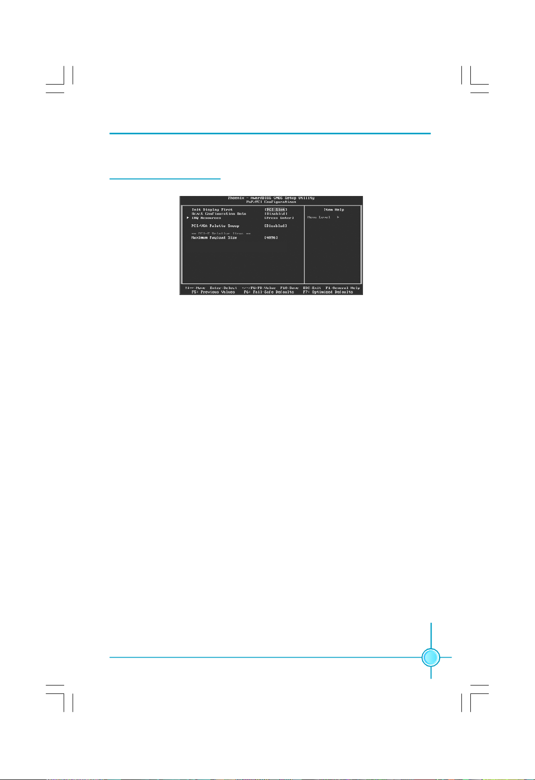
PnP/PCI Configurations
PnP/PCI Configurations Menu
v Init Display First
This option is used to set which display device will be used first when your PC
starts up.
v Reset Configuration Data
This option is used to set whether the system is permitted to automatically
distribute IRQ DMA and I/O addresses when each time that the machine is
turned on. The setting values are: Disabled and Enabled.
vIRQ Resources
Press the <Enter> key, then manually set IRQ resources.
vPCI/VGA Palette Snoop
If you use a non-standard VGA card, use this option to solve graphic acceleration card or MPEG audio card problems (e.g., colors not accurately displayed).
The setting values are: Disabled and Enabled.
vMaximum Payload Size
This option is used to set maximum TLP payload size for PCI Express devices.
The unit is byte.
43
Page 51
Chapter 3 BIOS Description
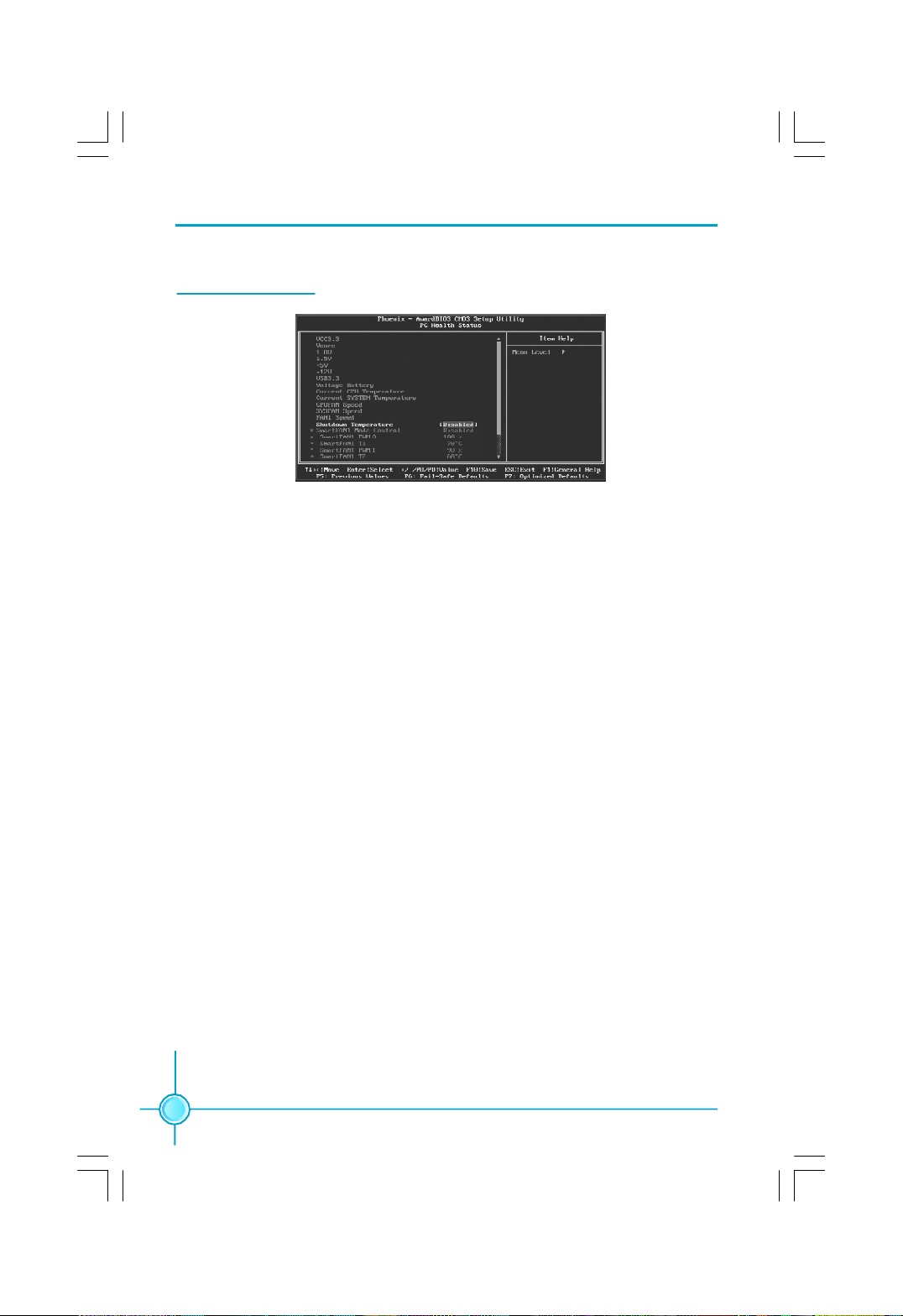
PC Health Status
PC Health Status Menu
vVCC 3.3/Vcore/1.8V/1.5V/+5V/+12V/VSB3.3/Voltage Battery
The current voltages will be automatically detected by the system.
vCurrent CPU/System Temperature
The current system/CPU temperature will be automatically detected by the
system.
vCPU/SYSTEM/FAN1 Speed
The system/CPU fan speed will be automatically detected by the system.
vShutdown Temperature
This option is used to set the system temperature upper limit. When the
temperature exceeds the setting value, the motherboard will automatically cut
off power to the computer.
Note: The following items can be adjusted when “FOX Intelligent Stepping”
has been set as “Manual”.
vSmart FAN1 Mode Control
This option is used to enable or disable smart fan function. “PWM Mode” can
enable smart fan function.
vSmart FAN1 PWM 0/1/2
This option is used to set smart fan1 PWM 0/1/2.
vSmart FAN1 T 1/2
This option is used to set smart fan1 temperature 1/2 value.
44
Page 52

Chapter 3 BIOS Description
Load Fail-Safe Defaults
Press <Enter> to select this option. A dialogue box will pop up that allows you to
load the default BIOS settings. Select <Y> and then press <Enter> to load the
defaults. Select <N> and press <Enter> to exit without loading. The defaults set by
BIOS set the basic system functions in order to ensure system stability. But if
your computer cannot POST properly, you should load the fail-safe defaults to
restore the original settings. Then carry out failure testing. If you only want to
load the defaults for a single option, you can select the desired option and
press the <F6> key.
Load Optimized Defaults
Select this option and press <Enter>, and a dialogue box will pop up to let you
load the optimized BIOS default settings. Select <Y> and then press <Enter> to
load the optimized defaults. Select <N> and press <Enter> to exit without loading.
The defaults set by BIOS are the optimized performance parameters for the
system, to improve the performance of your system components. However, if
the optimized performance parameters are not supported by your hardware
devices, it will likely cause system reliability and stability issues. If you only want
to load the optimized default for a single option, select the desired option and
press the <F7> key.
Set Supervisor/User Password
The access rights and permissions associated with the Supervisor password are
higher than those of a regular User password. The Supervisor password can be
used to start the system or modify the CMOS settings. The User password can
also start the system. While the User password can be used to view the current
CMOS settings, these settings cannot be modified using the User password.
When you select the Set Supervisor/User Password option, the following message
will appear in the center of the screen, which will help you to set the password:
Enter Password:
Enter your password, not exceeding 8 characters, then press <Enter>. The
password you enter will replace any previous password. When prompted, key in
the new password and press <Enter>.
45
Page 53

Chapter 3 BIOS Description
If you do not want to set a password, just press <Enter> when prompted to enter
a password, and in the screen the following message will appear. If no password
is keyed in, any user can enter the system and view/modify the CMOS settings.
Password Disabled!!!
Press any key to continue …
Under the menu “Advanced BIOS Features”, if you select “ System” from the
Security Option, you will be prompted to enter a password once the system is
started or whenever you want to enter the CMOS setting program. If the incorrect
password is entered, you will not be permitted to continue.
Under the menu “Advanced BIOS Features”, if you select “Setup” from the Secu-
rity Option, you will be prompted to enter a password only when you enter the
CMOS setting program.
Save & Exit Setup
When you select this option and press <Enter>, the following message will
appear in the center of the screen:
SAVE to CMOS and EXIT (Y/N)?Y
Press <Y> to save your changes in CMOS and exit the program; press <N> or
<ESC> to return to the main menu.
Exit Without Saving
If you select this option and press <Enter>, the following message will appear
in the center of the screen:
Quit Without Saving (Y/N)?N
Press <Y> to exit CMOS without saving your modifications; press <N> or <ESC>
to return to the main menu.
46
Page 54

Chapter 4 Driver CD Introduction
Chapter
4
4
The utility CD that came with the motherboard contains use-
ful software and several utility drivers that enhance the
motherboard features.
This chapter includes the following information:
v Utility CD content
v Installing drivers
v Installing Utilities
47
Page 55

Chapter 4 Driver CD Introduction
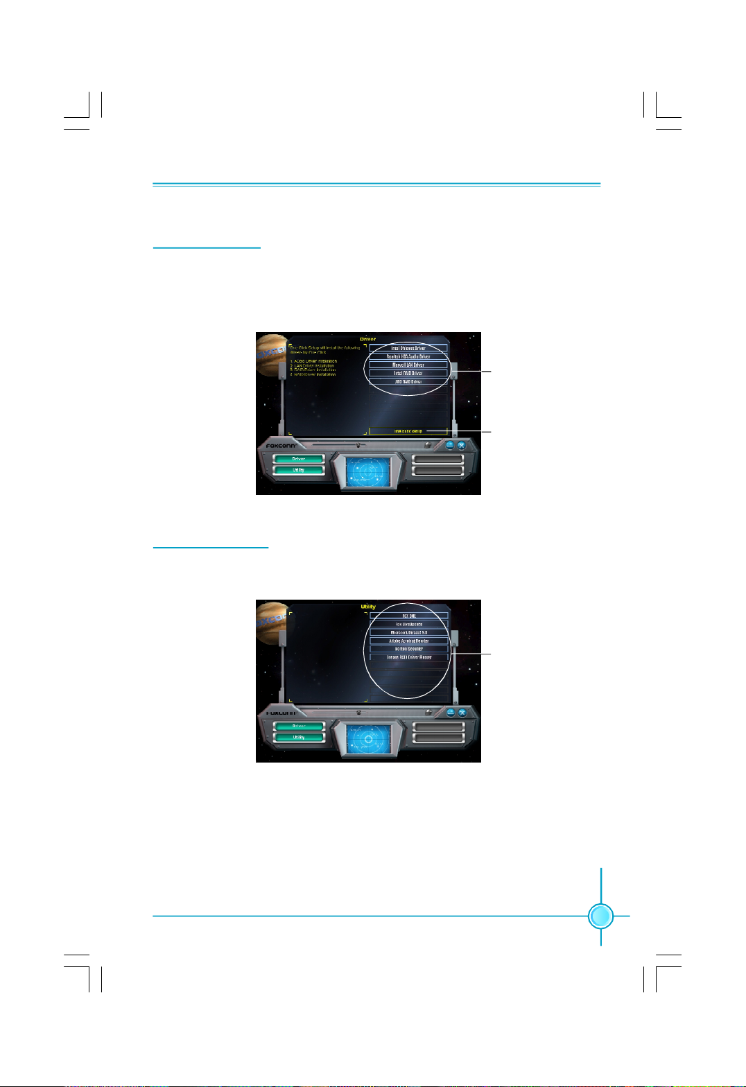
Utility CD content
This motherboard comes with one Utility CD. To begin using the CD, simply
insert the CD into your CD-ROM drive. The CD will automatically displays the
main menu screen.
1. Driver
Using this choice, you can install all the drivers for your motherboard. You should
install the drivers in order and you need to restart your computer after the drivers
all installed.
A. Intel Chipset Driver B. Realtek HDA Audio Driver
C. Marvell LAN Driver D. Intel RAID Driver
E. JMB RAID Driver
2. Utility
Using this choice, you can install all the additional software for your
motherboard.
A.FOX ONE
B.Fox LiveUpdate
C. Microsoft DirectX9.0
D.Adobe Acrobat Reader
E.Norton Security
F.Creat RAID Driver Floppy
3. Click on dynamic FOXCONN logo to visit our homepage.
48
Page 56
Chapter 4 Driver CD Introduction
Installing Drivers
There are two ways to install drivers, manual or automatic. Click the drivers that
you want to install and begin the setup steps by manual. Or you just click “One
Click Setup” button to install the drivers by automatic after install Intel Chipset
Driver.
Install by manual
Install by
automatic
Installing Utilities
You can select the utilities that you want to install and begin the setup steps.
Click here
49
Page 57

Page 58

Chapter 4 Driver CD Introduction
Chapter
5
5
This chapter will introduce how to use attached software.
This chapter provides the following information:
v FOX ONE
v Fox LiveUpdate
50
Page 59
Chapter 5 Directions for Bundled Software
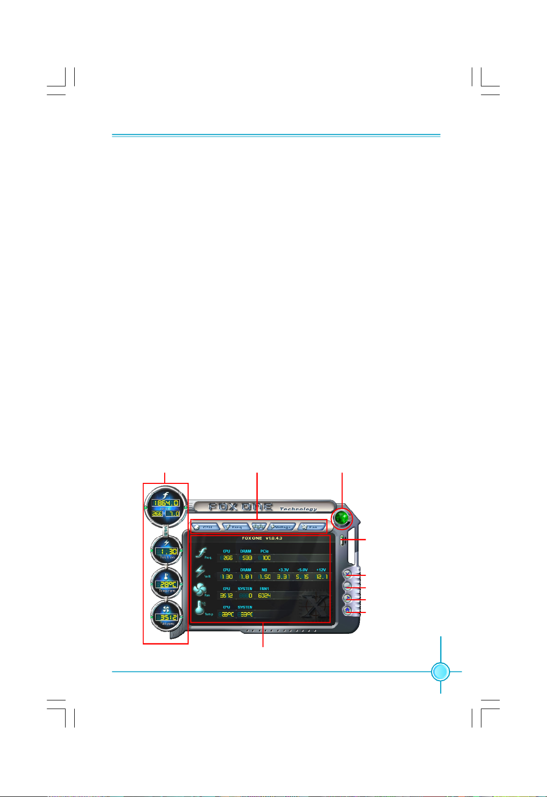
FOX ONE
FOX ONE is a powerful utility for easily modifying system settings. It also allows
users to monitor various temperature values, voltage values, frequency and fan
speed at any time.
With FOX ONE, you can
-Modify system performance settings, such as bus speeds, CPU voltages,
fan speed, and other system performance options that are supported by the
BIOS
-Monitor hardware temperature, voltage, frequency and fan speed
Supported Operating Systems:
-Windows 2000
-Windows XP
Using FOX ONE:
1. Main Page
Show CPU
Information
Toolbar
Monitor Frequency/Voltage/Fan
speed/Temperature value
Alert Lamp
Switch
Button
Exit
Minimum
Configuration
Homepage
51
Page 60

Chapter 5 Directions for Bundled Software
Toolbar
Use the toolbar to navigate to other pages.
Alert Lamp
When the system is in healthy status, the alert lamp color is green. When the
system is in abnormal status, the alert lamp color is red.
Switch Button
Click this button, it will shorten to below figure. It helps you to minitor your system
healthy status at any time.
Click here to return to
previous status
Exit
Click this button to exit the program.
Minimum
Click this button to minimize the window.
Configuration
Click this button to configurate the parameters for the program. It determines
which items will be shown in shorten mode.
Homepage
Click this button to visit Foxconn motherboard website.
2. CPU Page - CPU Control
This page lets you select and run the FOX ONE developed benchmarks to
determine the current performance level of the system. You can also adjust by
manual. Only this page is set to Manual Adjustment, the Freq., Vlotage, and Fan
pages can be adjusted by manual.
52
Page 61
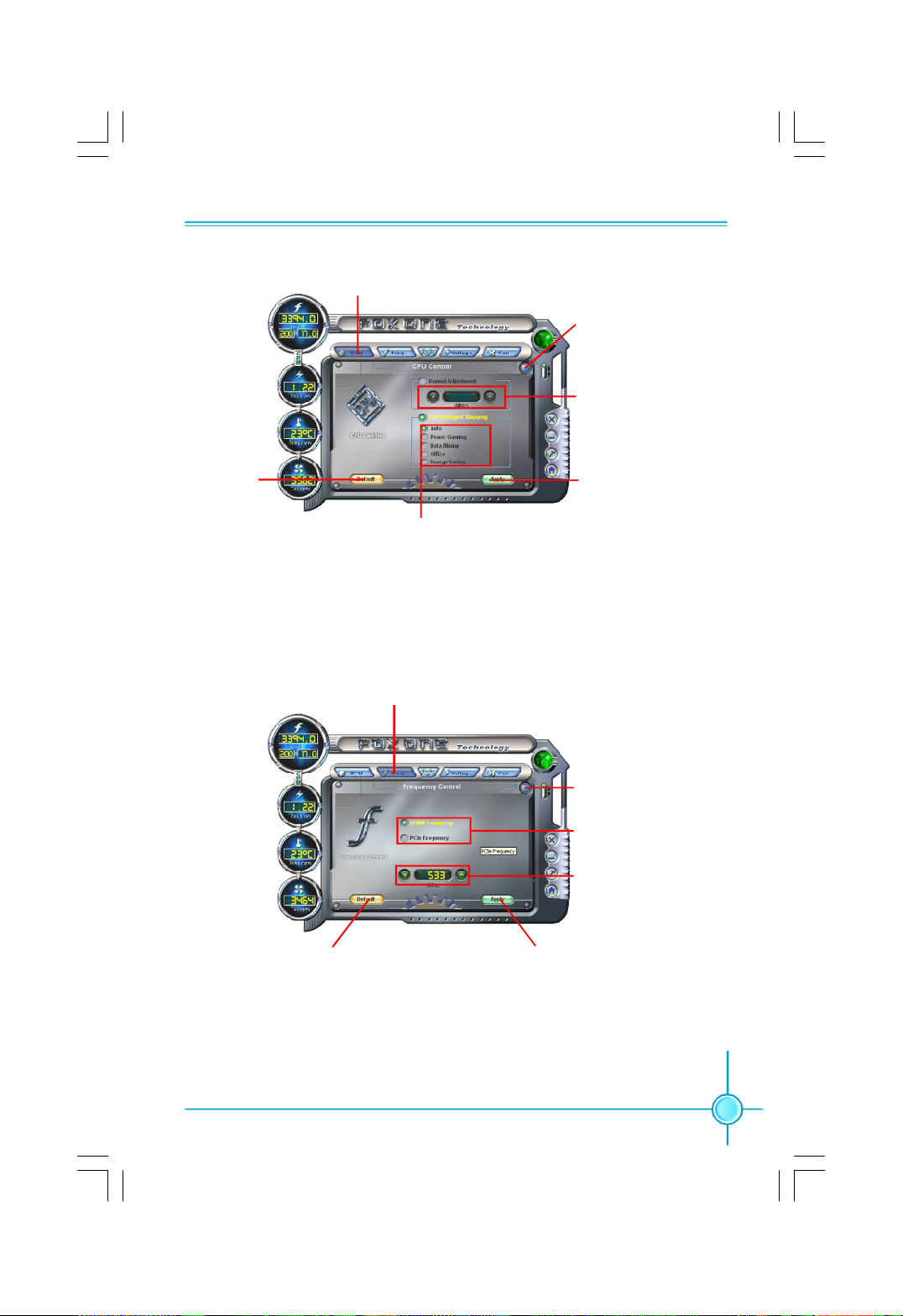
Chapter 5 Directions for Bundled Software
Go to CPU page
Close this page
Ajust by manual
Reset the
changes
Select the different
benchmarks
Apply the
changes
3. Freq. Page - Frequency Control
This page lets you set memory and PCI Express frequency by manual.
Go to Freq. page
Close this page
Select the option
you want to set
Adjust by manual
Reset the changes Apply the changes
53
Page 62
Chapter 5 Directions for Bundled Software
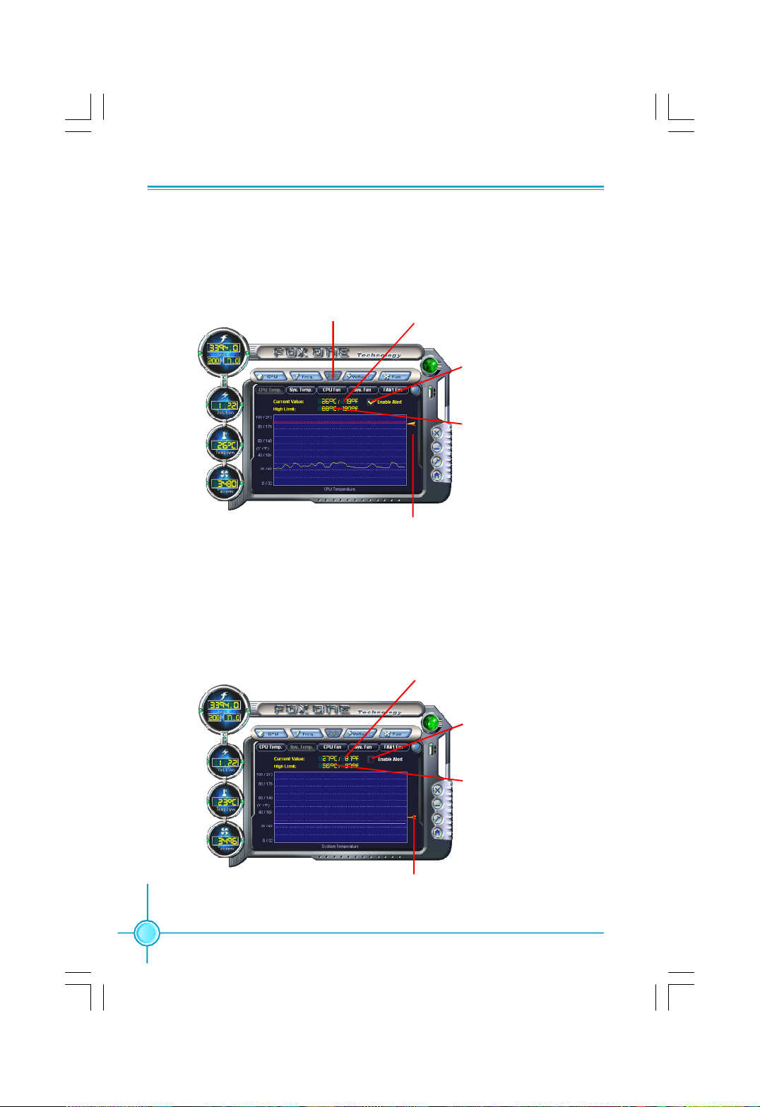
4.1 Limit Setting - CPU Temp.
This page lets you to set CPU high limit temperature and enable the alert
function.
Show current CPU
Go to Adjust page
temperature value
Enable alert function
when the CPU
temperature is higher
than high limit value
Show current high
limit value of CPU
temperature
Set high limit by
dragging the lever
4.2 Limit Setting - Sys Temp.
This page lets you to set system high limit temperature and enable the alert
function.
54
Show current system
temperature value
Enable alert function
when the system
temperature is higher
than high limit value
Show current high
limit value of system
temperature
Set high limit by
dragging the lever
Page 63
Chapter 5 Directions for Bundled Software
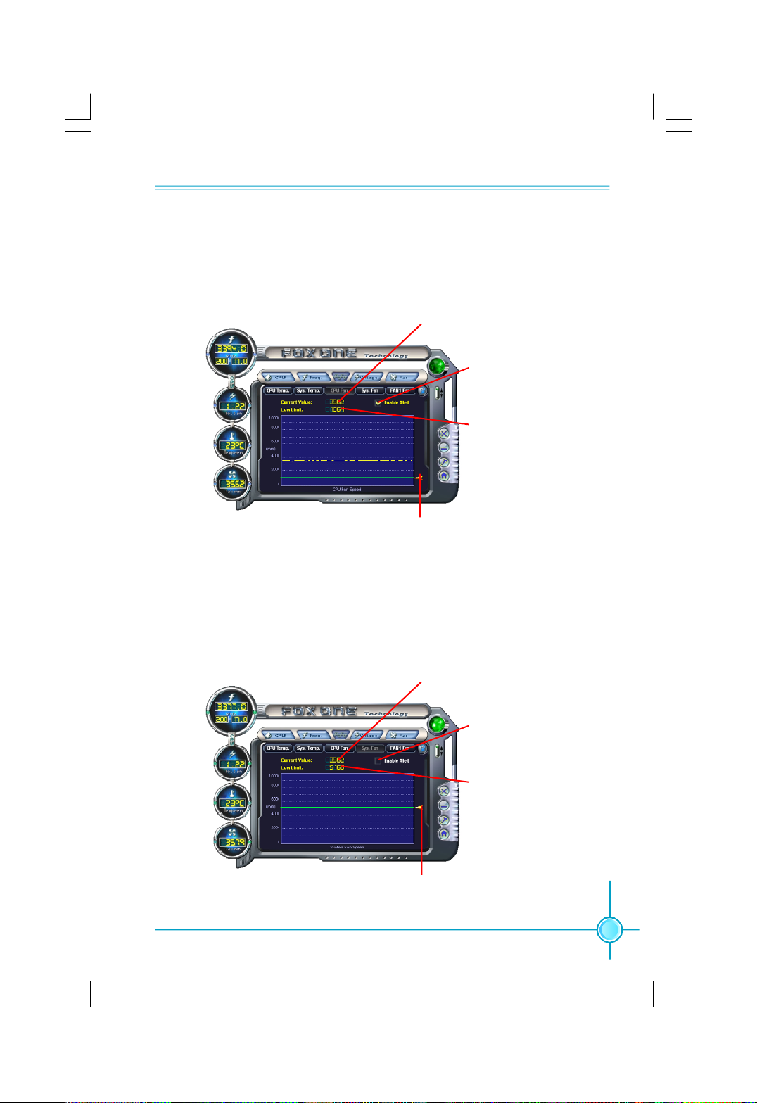
4.3 Limit Setting - CPU Fan
This page lets you to set CPU fan low limit rpm and enable the alert function.
Show current CPU
fan rpm value
Enable alert function
when the CPU fan rev
is lower than low limit
rpm value
Show current low limit
rpm value of CPU fan
Set low limit rpm by
dragging the lever
4.4 Limit Setting - Sys Fan
This page lets you to set system low limit rpm and enable the alert function.
Show current system
fan rpm value
Enable alert function
when the system fan
is lower than low limit
rpm value
Show current low limit
rpm value of system fan
Set low limit rpm by
dragging the lever
55
Page 64
Chapter 5 Directions for Bundled Software
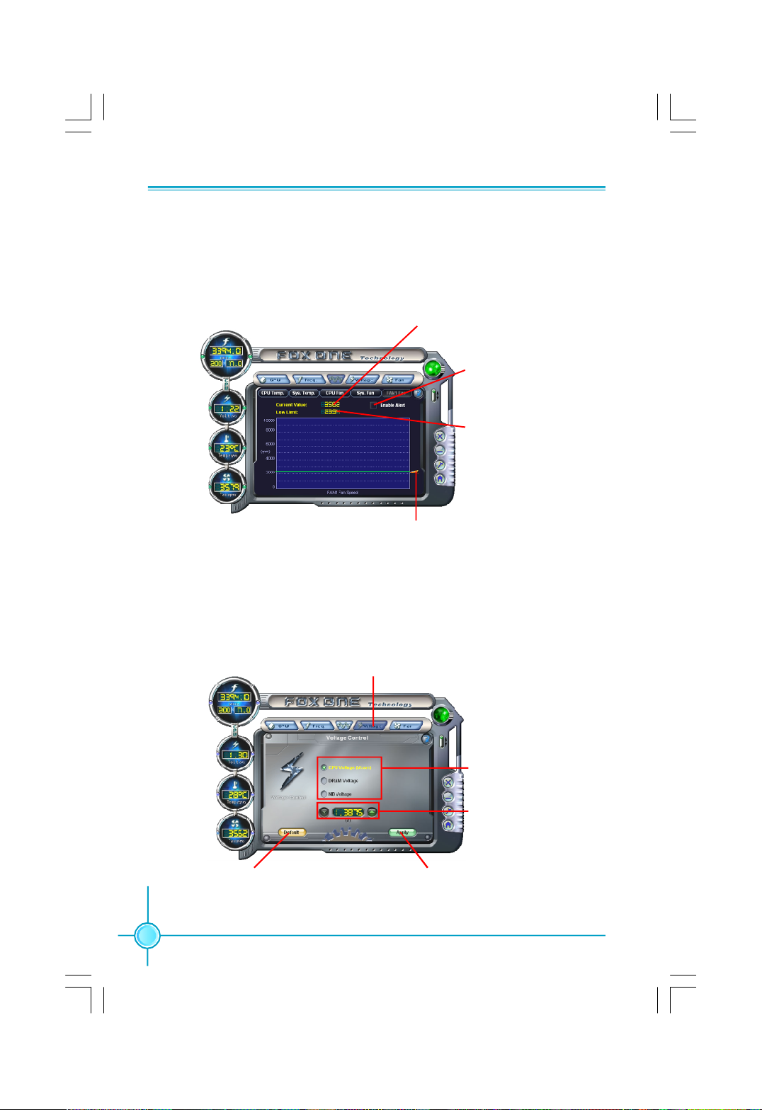
4.5 Limit Setting - Chassis Fan
This page lets you to set chassis fan low limit rpm and enable the alert function.
Show current Chassis
fan rpm value
Enable alert function when
the chassis fan is lower
than low limit rpm value
Show current low limit
rpm value of chassis fan
Set low limit rpm by
dragging the lever
5. Voltage Page - Voltage Control
This page lets you set CPU voltage, memory voltage and North Bridge voltage
by manual.
Go to Voltage page
Select the option
you want to set
Adjust by manual
Reset the changes Apply the changes
56
Page 65
Chapter 5 Directions for Bundled Software
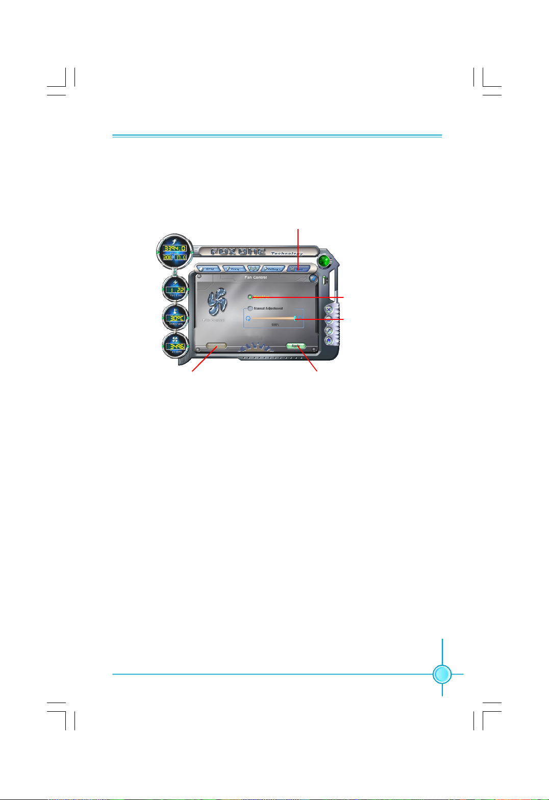
6. Fan Page - Fan Control
This page lets you enable smart Fan function or set fan speed by manual.
Go to Fan page
Enable or disable
smart fan function
Set fan speed by
dragging the lever
Reset the changes
Apply the changes
57
Page 66
Chapter 5 Directions for Bundled Software
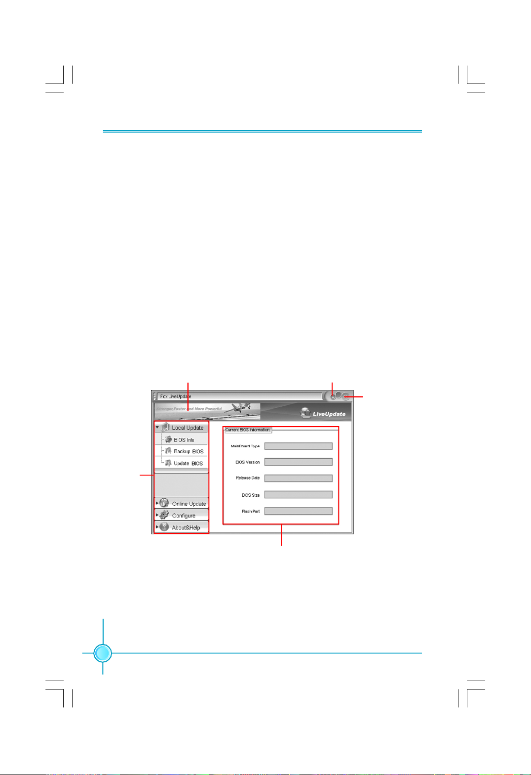
Fox LiveUpdate
Fox LiveUpdate is a useful utility for backuping and updating the system BIOS,
drivers and utilities by local or online.
Supported Operating Systems:
-Windows 2000
-Windows XP (32-bit and 64-bit)
-Windows 2003 (32-bit and 64-bit)
Using Fox LiveUpdate:
1.1 Local Update - BIOS Info.
This page lets you know your system BIOS information.
58
Toolbar
Link to website
Minimum
Exit
Show current
BIOS information
Page 67
Chapter 5 Directions for Bundled Software
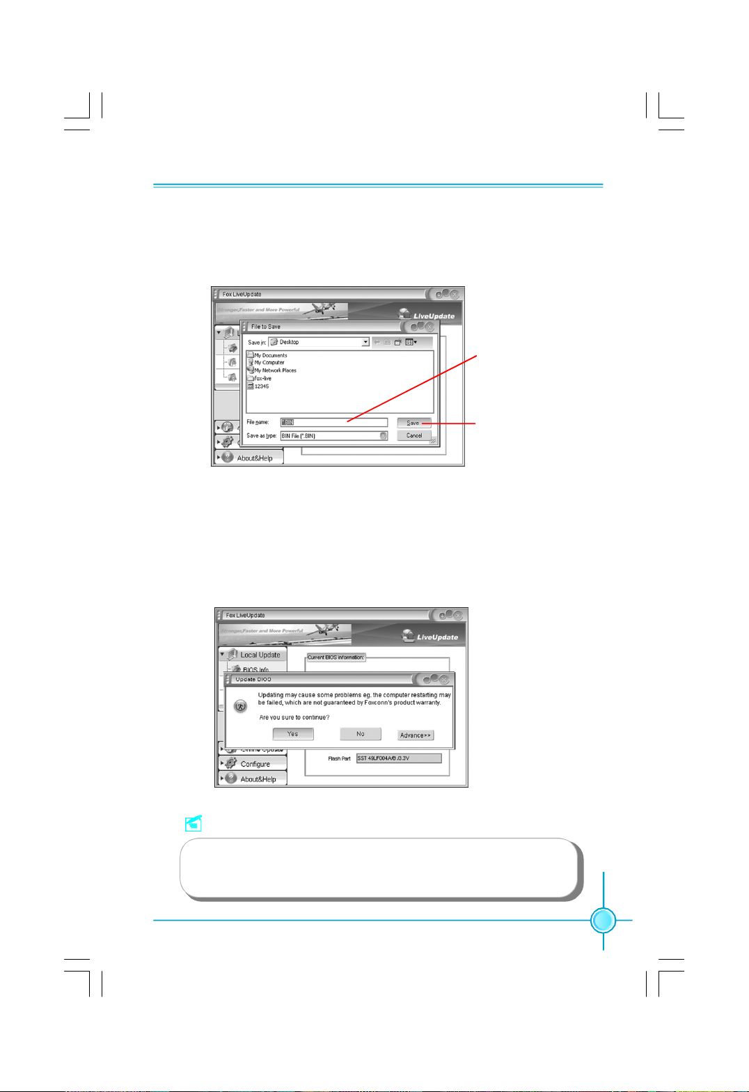
1.2 Local Update - Backup
This page lets you backup your system BIOS. Click “Backup”, then give a name.
Click “Save” to finish the backup operation.
Key in a BIOS name
Click here
1.3 Local Update - Update
This page lets you update your system BIOS from Internet. After click “Update”,
there will show warning message, please read it carefully. If you still want to
continue, click “Yes”. Then load a local BIOS file and follow the wizard to finish
the operation.
Note:
Fox LiveUpdate will auto backup BIOS before update because
we have enabled this function in Configure option.
59
Page 68
Chapter 5 Directions for Bundled Software
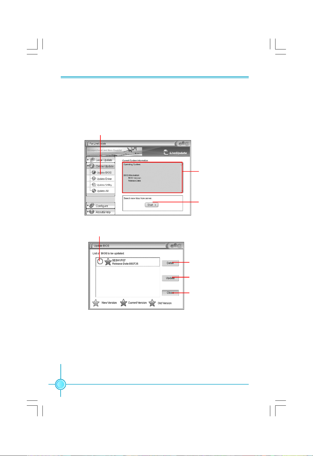
2.1 Online Update - Update BIOS
This page lets you update your system BIOS from Internet. Click “start”, it will
search the new BIOS from Internet. Then follow the wizard to finish the update
operation.
Click here
Current information
Search new BIOS
from Internet
Select BIOS to update
60
Browse detail
information
Update BIOS
Close the window
Page 69
Chapter 5 Directions for Bundled Software
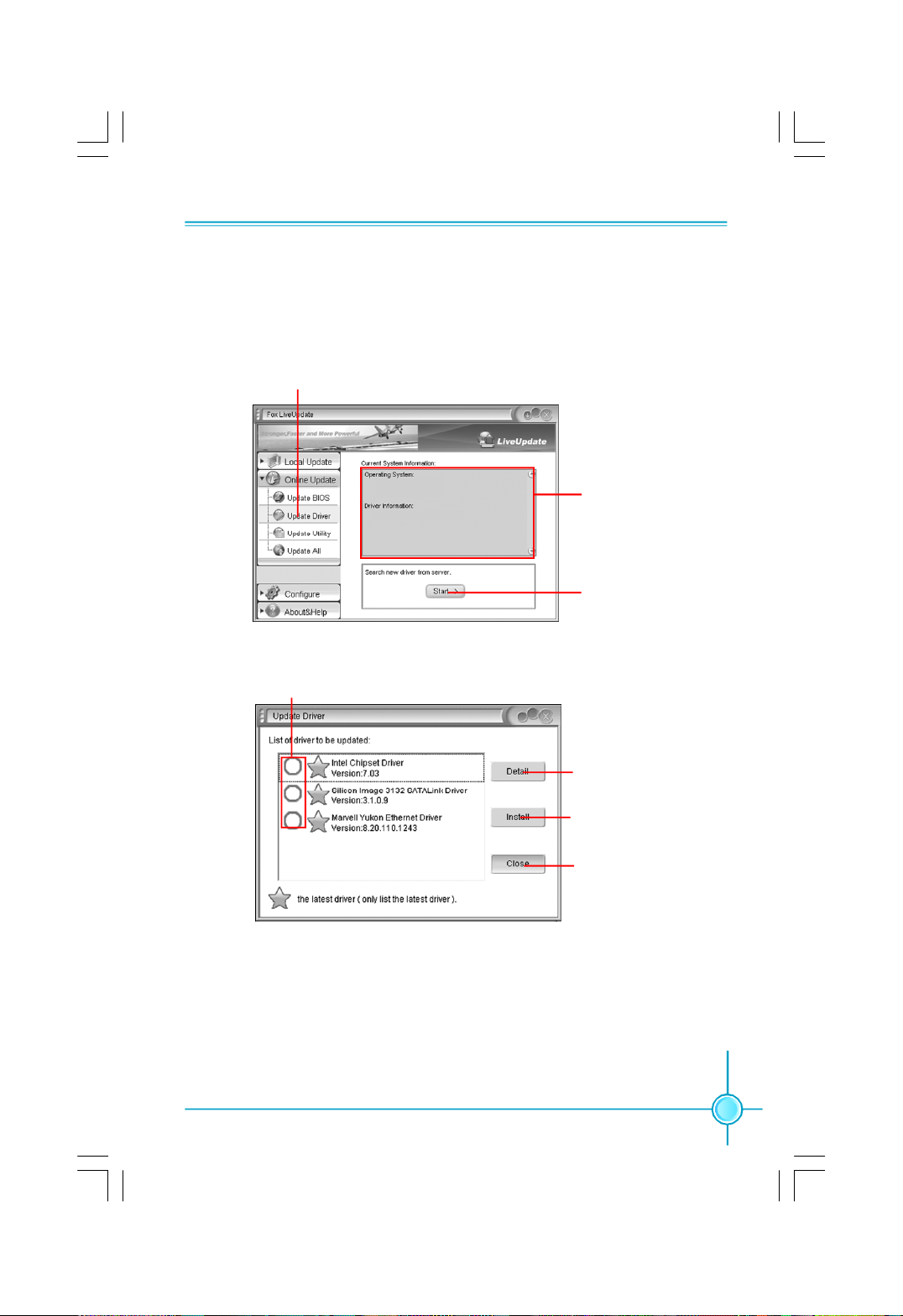
2.2 Online Update - Update Driver
This page lets you update your system drivers from Internet. Click “start”, it will
search the new drivers from Internet. Then follow the wizard to finish the update
operation.
Click here
Current information
Search new drivers
from Internet
Select the drivers to update
Browse detail
information
Install the selected
drivers
Close the window
61
Page 70
Chapter 5 Directions for Bundled Software
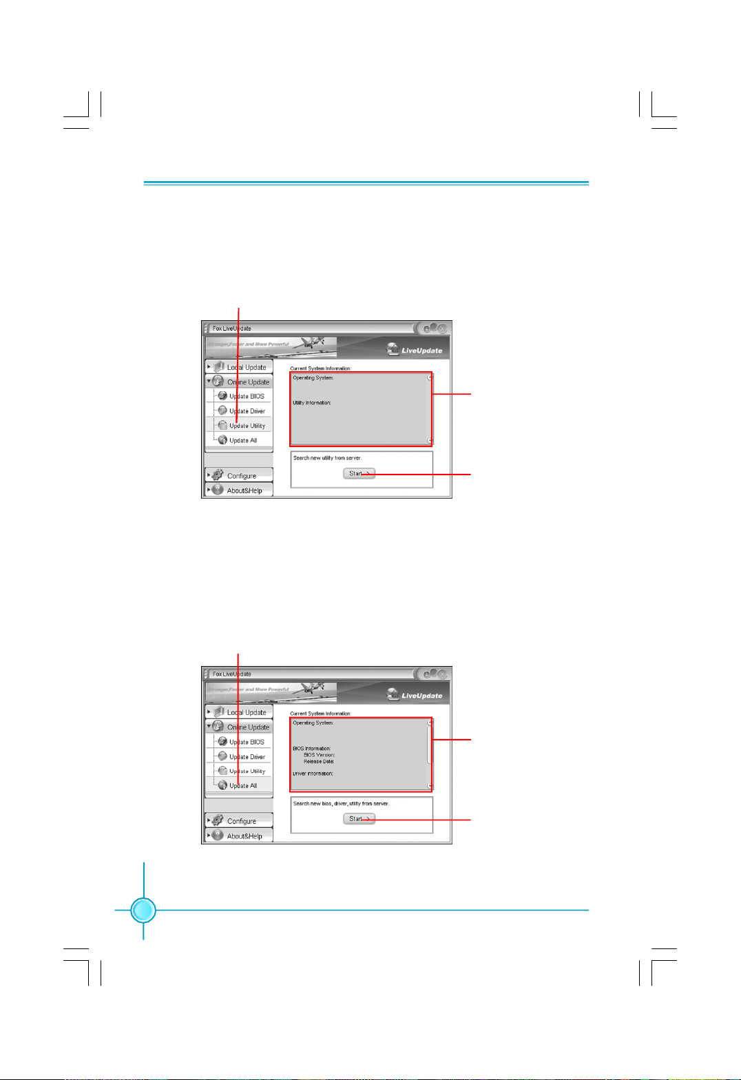
2.3 Online Update - Update Utility
This page lets you update utilities from Internet. Click “start”, it will search the new
utilities from Internet. Then follow the wizard to finish the update operation.
Click here
Current information
Search new utilities
from Internet
2.4 Online Update - Update All
This page lets you update your system drivers from Internet. Click “start”, it will
search all new BIOS/drivers/utilities from Internet. Then follow the wizard to finish
the update operation.
62
Click here
Current information
Search all new
BIOS/drivers/utilities
from Internet
Page 71
Chapter 5 Directions for Bundled Software
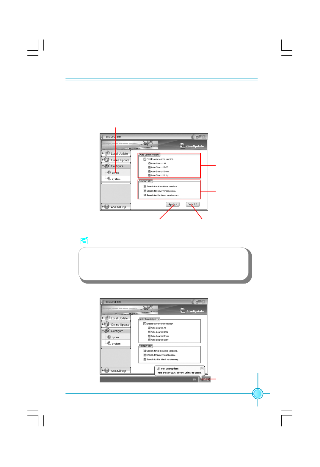
3.1 Configure - option
This page lets you set auto search options. After your setting, the utility will
start searching and related information will show on the task bar.
Click here
Set auto
search options
Select search
which kind of
versions
Apply the changes
Reset to default value
Note:
When enable auto search function, Fox LiveUpdate will appear
searching result on task-bar. Double click the icon, you can see the
detail information.
Double click here
63
Page 72
Chapter 5 Directions for Bundled Software
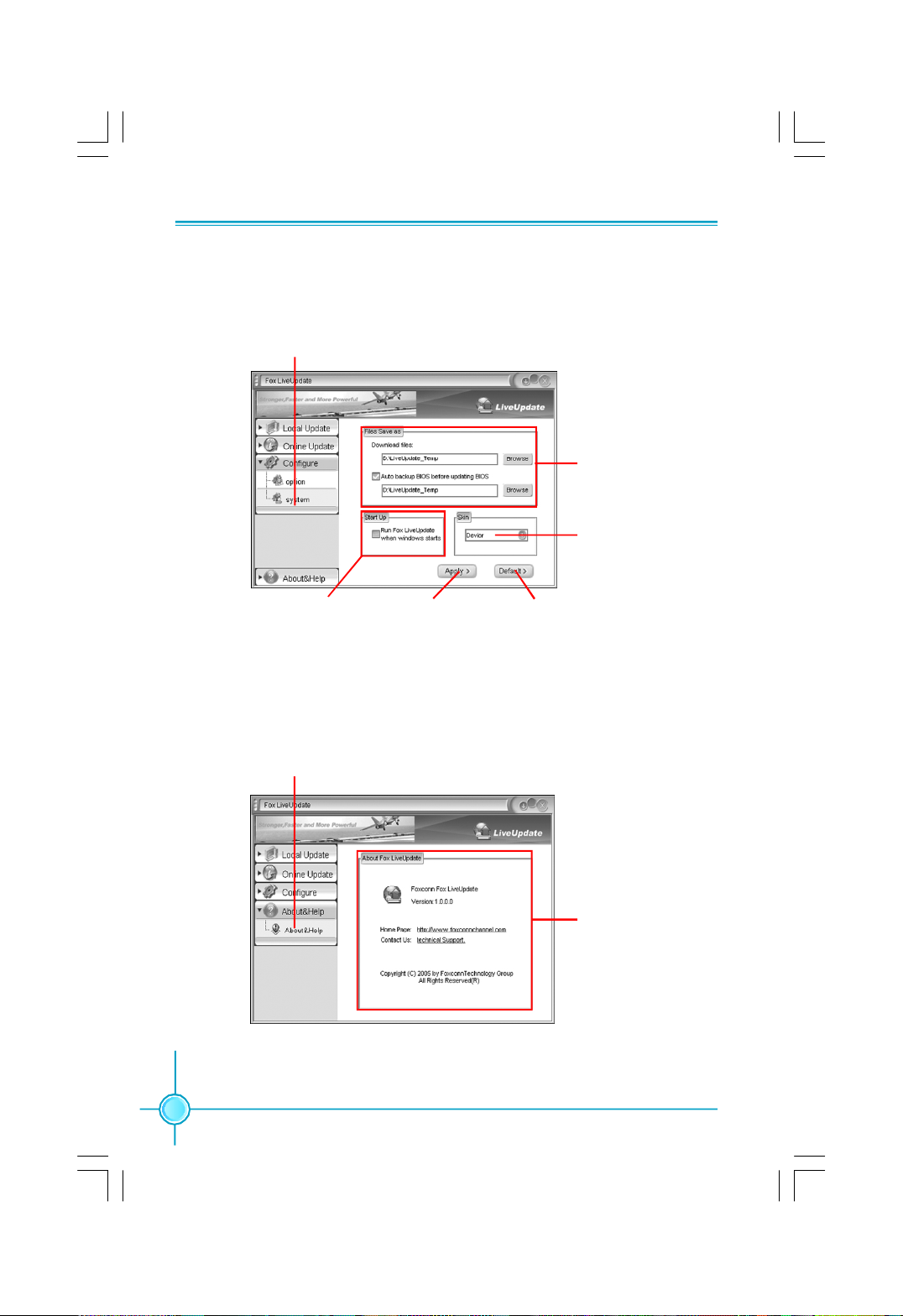
3.2 Configure - System
This page lets you set the backup BIOS location and change different skin of
the utility.
Click here
Set the location of
download files or
auto backup BIOS
Select different skin
of the software
Determine if the Fox
LiveUpdate can auto run
when the system starts up
Apply the changes
Reset to default value
4. About & Help
This page shows some information about Fox LiveUpdate.
Click here
Show information
about Fox LiveUpdate
64
Page 73

Appendix
CrossFire
Introduction
CrossFireTM technology is a recently introduced product from ATI Technologies
designed to dramatically improve the graphics performance of hardware and
software applications designed for gamers and other high-end users.
The CrossFireTM aspect requires the following components to be available in
order to appear as an option within CatalystTM Control Center:
- A CrossFireTM Ready motherboard such as Foxconn’s 975X7ABseries
- A CrossFireTM Edition graphics card that works as the master graphics card
- A CrossFireTM Ready graphics card from the same brand-family that works
as the slave graphics card
CrossFireTM Compatibility Chart
Master Card Slave Card
RadeonX1900 Crossfire Edition RadeonX1900 Series
Radeon X1800 Crossfire Edition Radeon X1800 Series
Radeon X1600 Series Radeon X1600 Series
TM
Technology
Radeon X1300 Series Radeon X1300 Series
Radeon X850 Crossfire Edition Radeon X850 Series
Radeon X800 Crossfire Edition Radeon X800, PRO, XL, GTO, XT or
XT Platinum Edition
Using CrossFire
Step 1. Install the Radeon CrossFireTM Edition graphics card to PCI_E_16X_1
slot.
Step 2. Install the Radeon CrossFireTM Ready graphics card to PCI_E_16X_2
slot.
TM
Technology
65
Page 74
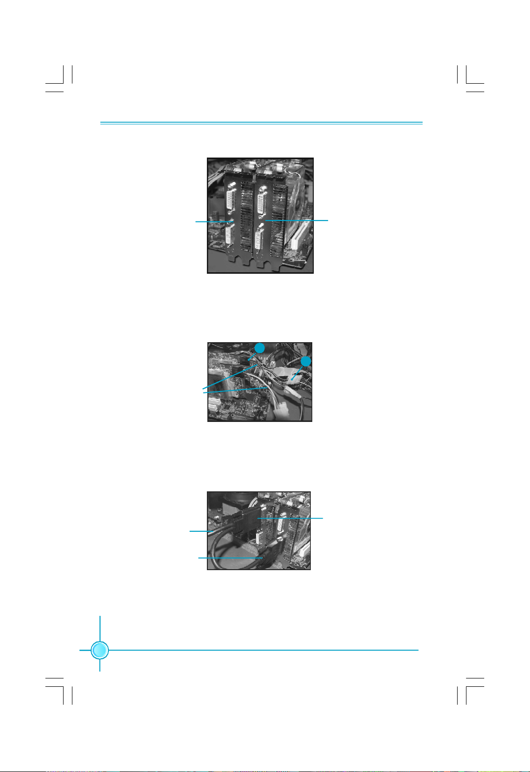
Appendix
CrossFireTM Edition
graphics card
CrossFireTM Ready
graphics card
Step 3. Connect 1 of the Power Extension Cable to the graphics card power
connector, and connect 2 to the power supply connector.
1
2
Power Extension Cable
Step 4. Correctly connect the DMS-59 cable to the DVI monitor connector and
two graphics cards that you install as shown.
Connect to monitor
Connect to slave graph-
ics card DVI connector
66
Connect to master graphics
card DMS connector
Page 75
Appendix
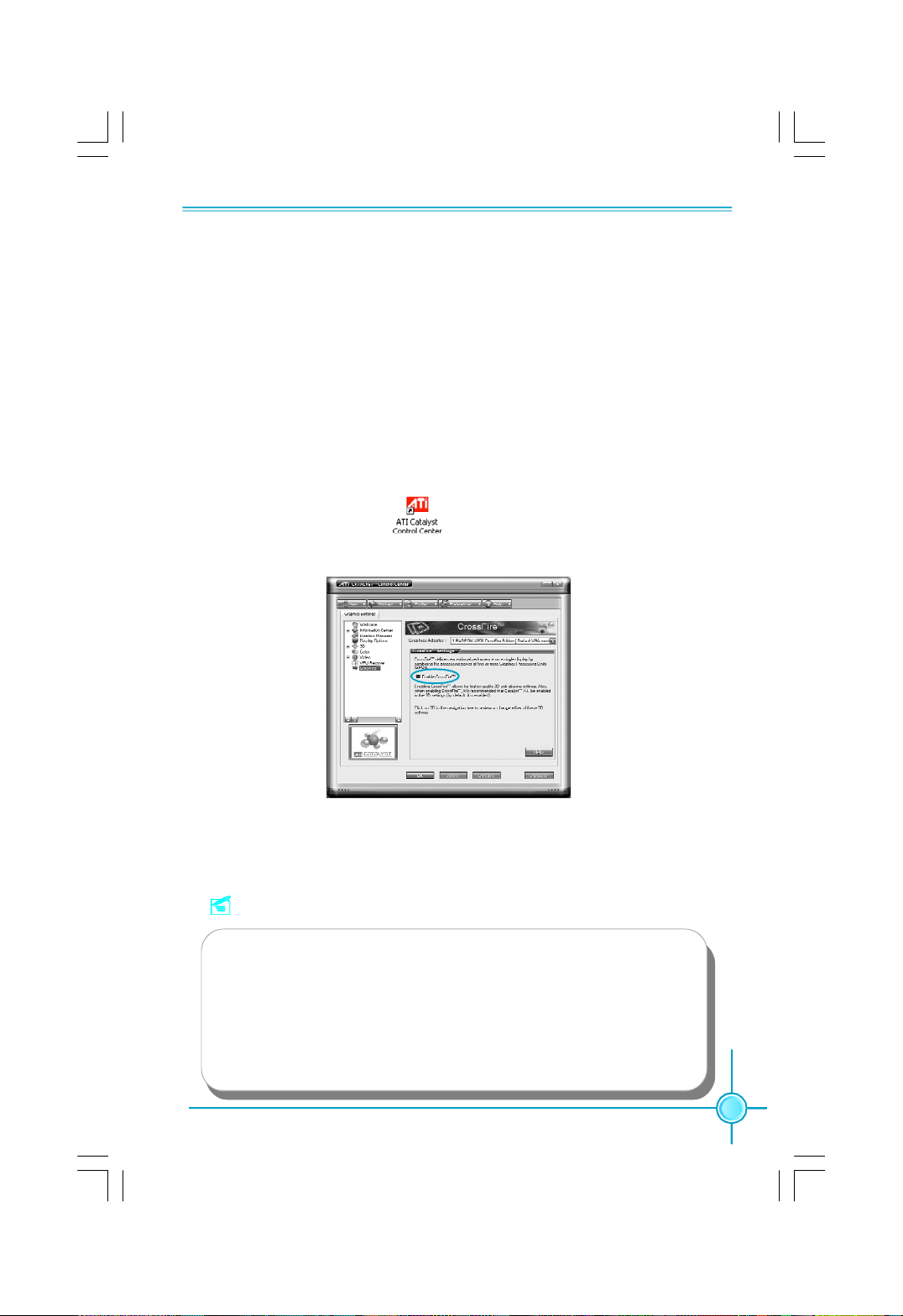
Step 5. Power on your computer and boot into OS (Windows XP with SP2 or
Windows XP Professional x64 Edition).
Step 6. Please uninstall any existing video drivers that could possibly create a
conflict before attempting to install this display card.
Step 7. Install Microsoft’s .NET Framework Version 1.1. Without it, The ATI Cata-
lyst Control Center will not launch properly.
Step 8. Install the ATI graphics card drivers and restart your computer. Then you
will find “ATI Catalyst Control Center” on your desktop.
Step 9. Double-click the icon to launch it. Click “View”-->Select
“Advanced View” -->Click “CrossFireTM”-->Set “Enable CrossFireTM” to Yes.
Now you can enjoy the advanced CrossFire
TM
technology.
Notes:
1. It is recommended to use 500 W power supply or above to enjoy the
benefit of CrossFireTM technology.
2. Both PCI Express x16 slots will work in 8x mode, when you use
CrossFireTM technology.
3. The all-new Radeon X1300 and X1600 graphics cards do not need
a CrossFire Edition co-processor or external cable.
67
Page 76
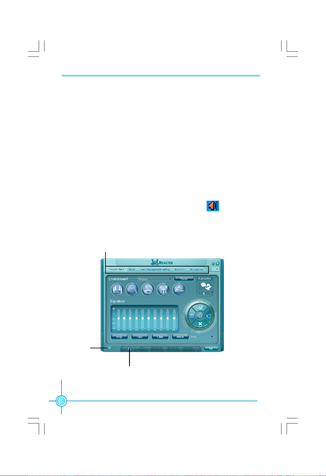
Appendix
Audio Configuration
The ALC882 provide 10 channels of DAC that simultaneously support 7.1 sound
playback, plus 2 channels of independent stereo sound output (multiple
streaming) through the Front-Out-Left and Front-Out-Right channels. Flexible
mixing, mute, and fine gain control functions provide a complete integrated
audio solution for next generation multimedia PCs.
Now we will tell you how to install audio driver and use Realtek HD Audio
Manager.
1. Click “Audio Driver” button and follow the installation wizard to install Realtek
audio diver from Driver CD.
2. After the driver is correctly installed, you will find the icon on the task bar.
Double click it to display the Realtek HD Audio Manager.
3. Main Menu Introduction
Configuration options
Information
68
button
Tool button
Page 77
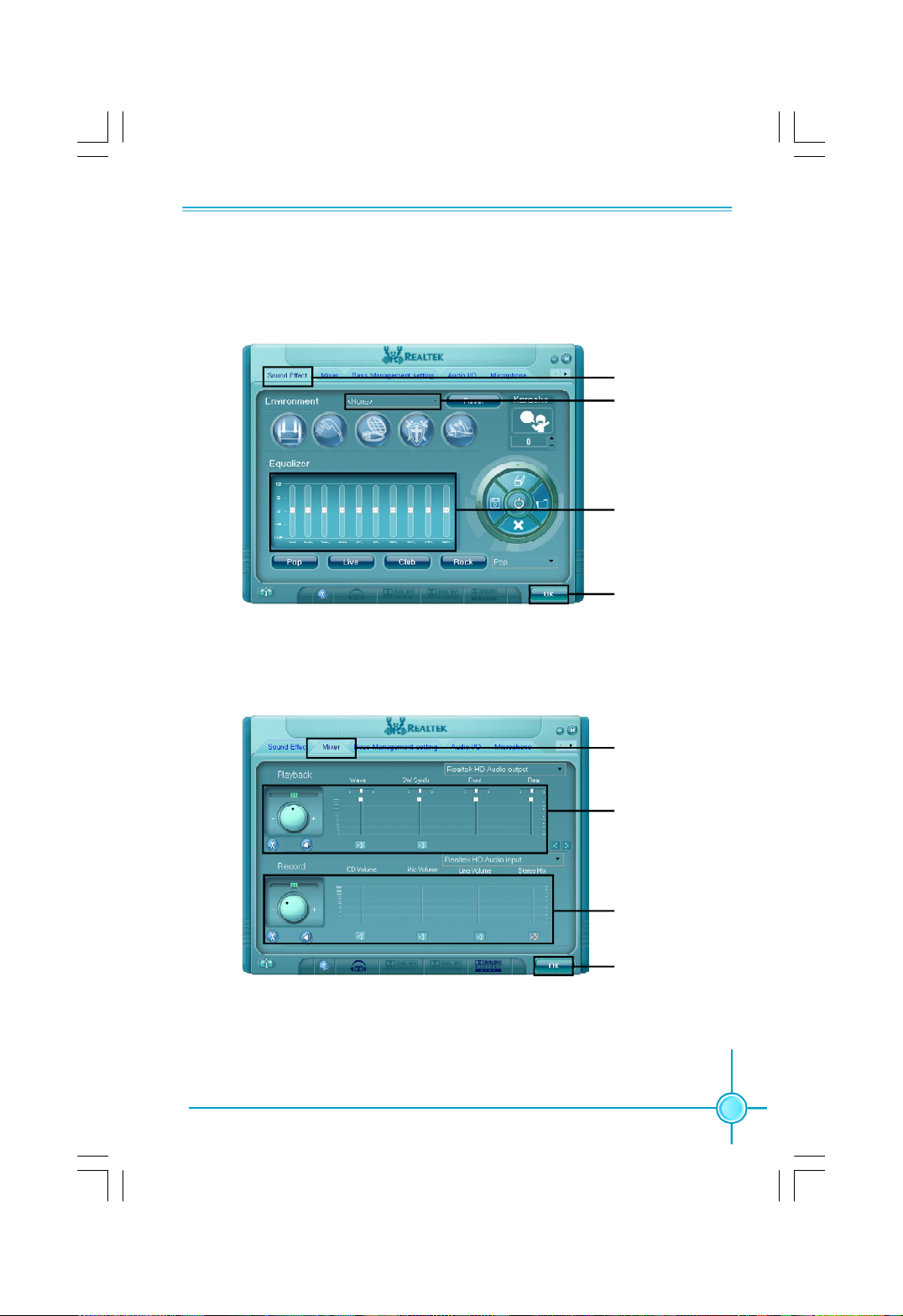
Appendix
4. Sound Effect Introduction
Allows you to set your listening environment, adjust the equalizer, set the Karaoke,
or select pre-programmed equalizer settings.
1. Click here
2. Select
environment
3. Set equalizer
4. Click OK
5. Mixer Introduction
Allows you to set audio output and audio input volume.
1. Click here
2. Set playback
3. Set record
4. Click OK
69
Page 78
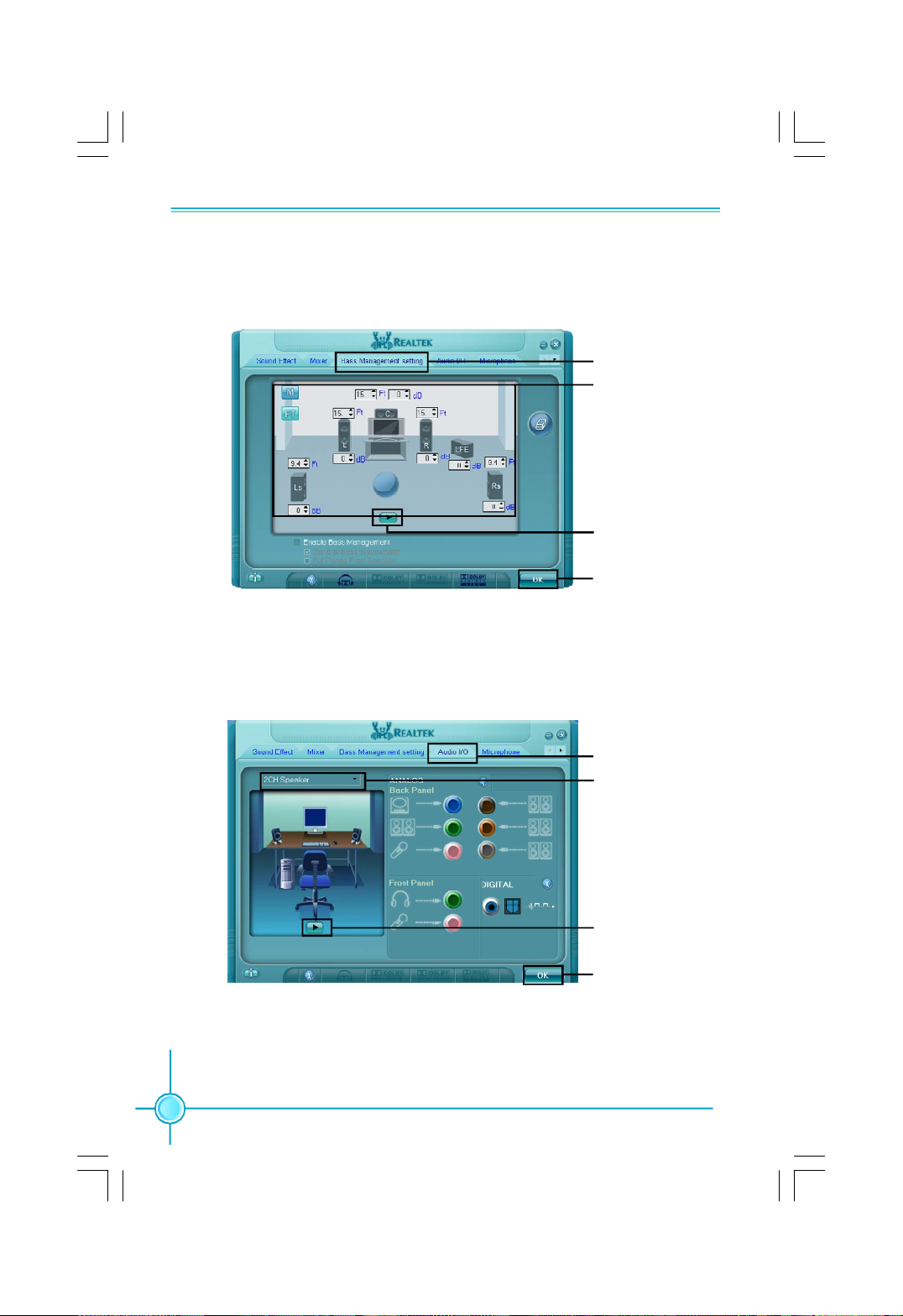
6. Bass Management setting Introduction
Allows you to manage your bass settings.
7. Audio I/O Introduction
Allows you to configure your input/output settings.
Appendix
1. Click here
2. Adjust your
desired settings
3. Test your
settings
4. Click OK
70
1. Click here
2. Select channel
configuration
3. Test
4. Click OK
Page 79
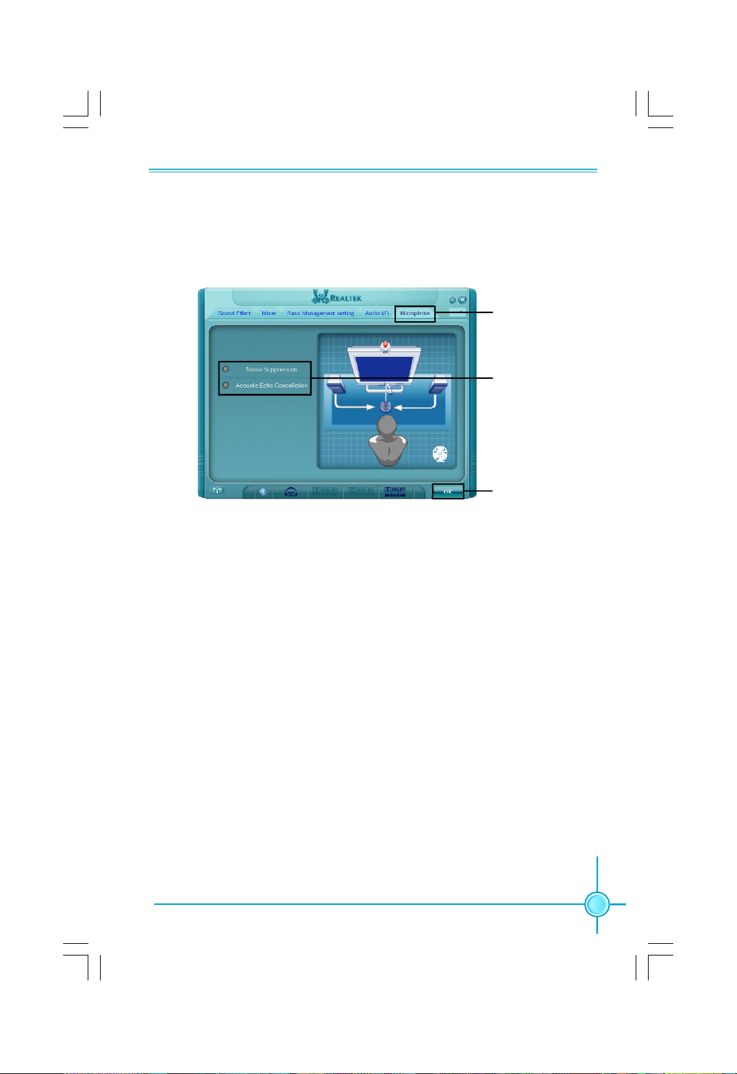
Appendix
8. Microphone Introduction
Allows you to configure your input/output settings and to check if your audio
devices are connected properly.
1. Click here
2. Click here
3. Click OK
71
 Loading...