

Foxconn 915G, 915GV, 915P, 915PL, 910GL7MH Series User Manual
...
This manual is the intellectual property of Foxconn, Inc. Although the
information in this manual may be changed or modified at any time,
Foxconn does not obligate itself to inform the user of these changes.
Statement:
All trademarks are the property of their respective owners.
More information:
If you want more information about our products, please visit Foxconn’s
website: h
ttp://www.foxconnchannel.com
Version:
Trademark:
User’s Manual V1.0 in English for 915G/P/GL/GV/PL/910GL7MH motherboard.
P/N: 91-181-915-MB-0E
Symbol description:
Note: refers to important information that can help you to use motherboard
better.
Attention: indicates that it may damage hardware or cause data loss,
and tells you how to avoid such problems.
Warning: means that a potential risk of property damage or physical
injury exists.
Declaration of conformity
HON HAI PRECISION INDUSTRY COMPANY LTD
66 , CHUNG SHAN RD., TU-CHENG INDUSTRIAL DISTRICT,
TAIPEI HSIEN, TAIWAN, R.O.C.
declares that the product
Motherboard
915G/P/GL/GV/PL/910GL7MH
is in conformity with
(reference to the specification under which conformity is declared in
accordance with 89/336 EEC-EMC Directive)
þ EN 55022: 1998/A2 Limits and methods of measurements of radio disturbance
characteristics of information technology equipment
þ EN 61000-3-2/:2000 Electromagnetic compatibility (EMC)
Part 3: Limits
Section 2: Limits for harmonic current emissions
(equipment input current <= 16A per phase)
þ EN 61000-3-3/A1:2001 Electromagnetic compatibility (EMC)
Part 3: Limits
Section 2: Limits of voltage fluctuations and flicker in low-voltage
supply systems for equipment with rated current <= 16A
þ EN 55024/A2:2003 Information technology equipment-Immunity characteristics limits
and methods of measurement
Signature : Place / Date : TAIPEI/2005
Printed Name : James Liang Position/ Title : Assistant President

Declaration of conformity
Trade Name: FOXCONN
Model Name: 915G/P/GL/GV/PL/910GL7MH
Responsible Party: PCE Industry Inc.
Address: 458 E. Lambert Rd.
Fullerton, CA 92835
Telephone: 714-738-8868
Facsimile: 714-738-8838
Equipment Classification: FCC Class B Subassembly
Type of Product: Motherboard
Manufacturer: HON HAI PRECISION INDUSTRY
COMPANY LTD
Address: 66 , CHUNG SHAN RD., TU-CHENG
INDUSTRIAL DISTRICT, TAIPEI HSIEN,
TAIWAN, R.O.C.
Supplementary Information:
This device complies with Part 15 of the FCC Rules. Operation is subject to the
following two conditions : (1) this device may not cause harmful interference, and (2)
this device must accept any interference received, including interference that may
cause undesired operation.
Tested to comply with FCC standards.
Signature : Date : 2005

Table of Contents
Product Introduction
Main Features............................................................................................2
Layout........................................................................................................4
Rear I/O Ports............................................................................................. 5
Installation Instructions
CPU...........................................................................................................7
Memory....................................................................................................10
Power Supply.......................................................................................... 12
Other Connectors.....................................................................................13
Expansion Slots........................................................................................17
Jumpers...................................................................................................19
BIOS Description
Enter BIOS Setup......................................................................................22
Main menu................................................................................................22
Standard CMOS Features.........................................................................24
BIOS Features.......................................................................................... 27
Advanced BIOS Features......................................................................... 29
Advanced Chipset Features..................................................................... 33
Integrated Peripherals............................................................................... 36
Power Management Setup........................................................................ 40
PnP/PCI Configurations............................................................................. 45
PC Health Status....................................................................................... 46
Load Fail-Safe Defaults............................................................................ 48
Load Optimized Defaults........................................................................... 48
Set Supervisor/User Password................................................................48
Save & Exit Setup..................................................................................... 49
Exit Without Saving................................................................................... 49
Chapter
1
1
Chapter
2
2
Chapter
3
3

Driver CD Introduction
Utility CD content......................................................................................51
Start to install drivers...............................................................................52
Directions for Bundled Software
SuperStep...............................................................................................54
SuperUpdate............................................................................................57
SuperLogo...............................................................................................61
Special BIOS Functions
SuperBoot...............................................................................................64
SuperBIOS-Protect...................................................................................65
SuperRecovery.......................................................................................66
SuperSpeed.............................................................................................75
Table of Contents
4
4
Chapter
Chapter
Chapter
5
5
6
6
1.Attach the CPU and heatsink using silica gel to ensure full contact.
2.It is suggested to select high-quality, certified fans in order to avoid
damage to the motherboard and CPU due high temperatures.
3.Never turn on the machine if the CPU fan is not properly installed.
4.Ensure that the DC power supply is turned off before inserting or
removing expansion cards or other peripherals, especially when
you insert or remove a memory module. Failure to switch off the DC
power supply may result in serious damage to your system or
memory module.
Warning:
We cannot guarantee that your system will operate normally while
over-clocked. Normal operation depends on the over-clock capacity
of your device.
Warning:
Attention:
Since BIOS programs are upgraded from time to time, the BIOS
description in this manual is just for reference. We do not guarantee
that the content of this manual will remain consistent with the actual
BIOS version at any given time in the future.
Attention:
The pictures of objects used in this manual are just for your reference.
Please refer to the physical motherboard.

This manual is suitable for motherboard of 915G/P/GL/GV/PL/
910GL7MH. Each motherboard is carefully designed for the PC
user who wants diverse features.
-L with onboard 10/100M LAN
-K with onboard Giga LAN
-6 with 6-Channel audio
-8 with 8-Channel audio
-E with 1394 function
-S with SATA function
-R with RAID function
You can find PPID label on the motherboard. It indicates the
functions that the motherboard has.
For example:
On the blue mark of the PPID label, it means the motherboard
supports 6-Channel Audio(-6), 1394 port(-E), onboard 10/100M
LAN (-L), SATA function(-S).
Chapter
Thank you for buying Foxconn’s 915 series motherboard. This
series of motherboard is one of our new products, and offers
superior performance, reliability and quality, at a reasonable
price. This motherboard adopts the advanced Intel® 915G/P/
GL/GV/PL/910GL+ ICH6/ICH6R chipset, providing users a com-
puter platform with a high integration-compatibility-performance
price ratio.
This chapter includes the following information:
v Main Features
v Motherboard Layout
v Rear I/O Ports
1
1

Chapter 1 Product Introduction
2
Main Features
Size
· mATX form factor of 9.6 inch x 9.6 inch
Microprocessor
· supports Intel® Pentium® 4, or Celeron® D processor in anLGA775 pack-
age
· Supports FSB at 533 MHz/800 MHz (910GL7MH does not support FSB 800MHz)
· Supports Hyper-Threading technology
Chipset
· 915G7MH series: Intel® 915G + ICH6/6R
· 915P7MH series: Intel® 915P + ICH6/6R
· 915GV7MH series: Intel® 915GV + ICH6/6R
· 915GL7MH series: Intel® 915GL + ICH6/6R
· 915PL7MH series: Intel® 915PL + ICH6/6R
· 910GL7MH series: Intel® 910GL + ICH6/6R
System Memory
· 915G/P/GV7MH series
Two 184-pin DIMM slots and two 240-pin DIMM slots
Supports Dual-Channel DDR 333/400 and Dual-Channel DDR2 533/400
·915GL/PL/910GL7MH series
Two 184-pin DIMM slots
Supports Dual-Channel DDR 333/400
USB 2.0 Ports
· Supports hot plug
· Eight USB 2.0 ports
· Supports wake-up from S1 and S3 mode
· Supports USB 2.0 Protocol up to 480 Mbps transmission rate
Onboard Serial ATA (-S)(optional)
· 150 MBps transfer rate
· Supports four S-ATA devices
· Supports RAID 0, RAID 1, Matrix RAID (supported on ICH6R)

3
Chapter 1 Product Introduction
Onboard LAN (-L)
· Supports 10/100 Mbit/sec Ethernet
· LAN interface built-in on board
Onboard Audio (-6)
· AC’97 2.3 Specification Compliant
· Supports SPDIF output
· Onboard Line-in jack, Microphone jack, Line-out jack
· Supports 6-Channel audio (setting via software)
Onboard Graphics (only for 915G/GV/GL/910GL7MH series)
· Supports integrated VGA display function (Intel
®
Graphics Media
Accelerator 900)
PCI Express x16 Support (only for 915G/P/PL7MH series)
· Supports 4 GB/sec (8 GB/sec concurrent) bandwidth
· Low power consumption and power management features
F.G.E.II Support (only for 915GV/GL/910GL7MH series)
· Compatible with PCI Express x16 specification
· Supports facile dual monitor feature
Green Function
· Supports ACPI (Advanced Configuration and Power Interface)
· Supports S0 (normal), S1 (power on suspend), S3 (suspend to RAM), S4
(Suspend to disk - depends on OS), and S5 (soft - off)
Expansion Slots
· Three PCI slots
· One PCI Express x16 Graphics slot (only for 915G/P/PL7MH series) or
F.G.E.II slot (only for 915GV/GL/910GL7MH series)
Advanced Features
· PCI 2.3 specification compliant
· Supports Windows 2000/XP soft-off
· Supports PC Health function (capable of monitoring system voltage, CPU
temperature, system temperature, and fan speed)
Chapter 1 Product Introduction
4
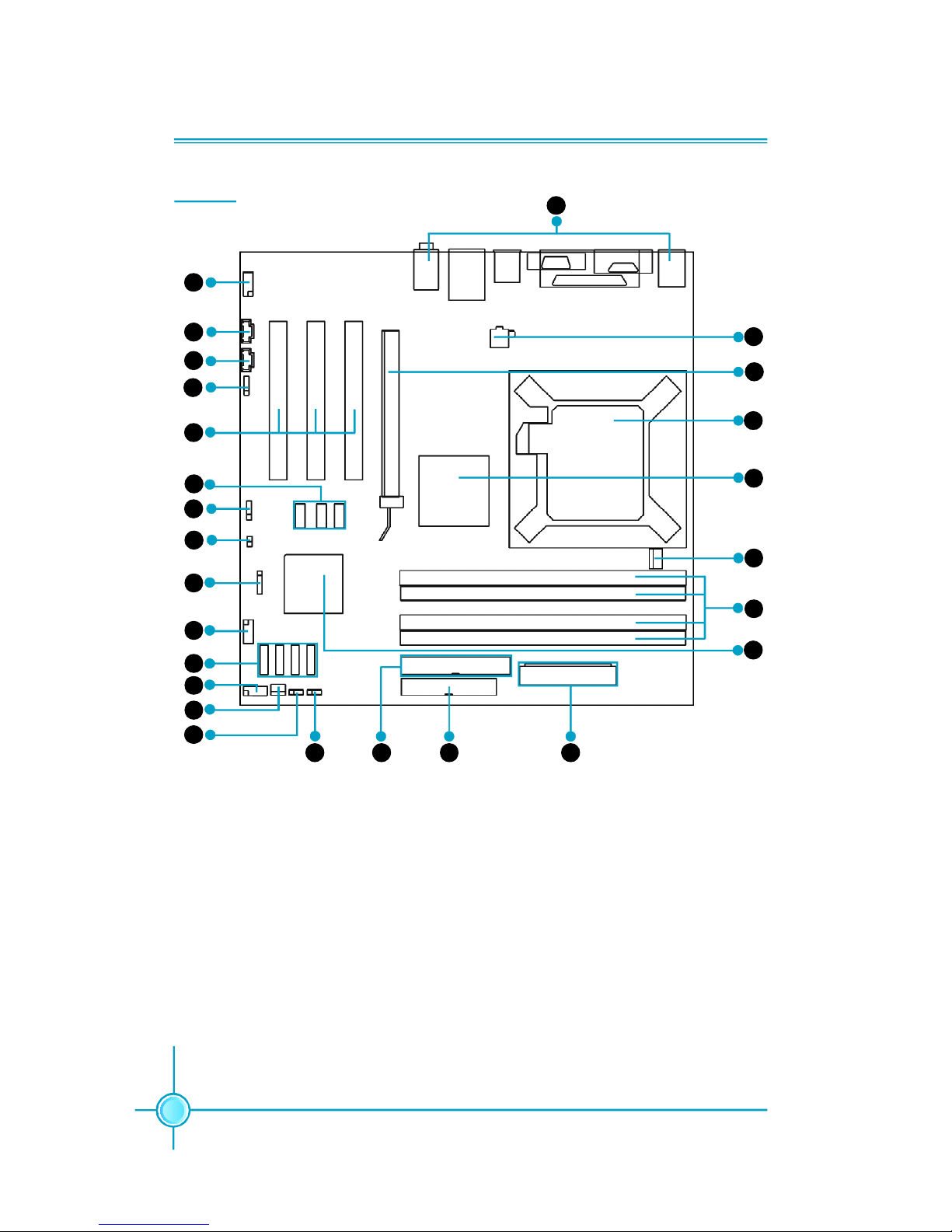
14. Clear CMOS Jumper
15. BIOS TBL Jumper (optional)
16. ATA 100/66/33 Connector
17. FDD Connector
18. 24-pin ATX Power Connector
19. South Bridge: ICH6/ICH6R Chipset
20. DIMM Slots
21. CPU_FAN Connector
22. North Bridge: 915G/P/GL/GV/PL/
910GL Chipset
23. LGA775 CPU Socket
24. PCI Express x16 Slot/F.G.E.II Slot
25. 4-pin ATX_12V Power Connector
26. Rear I/O Ports
1. Front Audio Connector
2. CD_IN Connector
3. AUX_IN Connector
4. SPDIF Out Connector (optional)
5. PCI Slots
6. USB Connectors (optional)
7. Speaker Connector (optional)
8. Chassis Intruder Connector
9. IrDA Connector
10. COM2 Connector
11. Serial ATA Connectors
12. Front Panel Connector
13. SYS_FAN Connector
Layout
17
25
24
23
22
21
20
18
14
1615
12
13
11
9
6
3
2
5
1
19
7
4
10
26
8
5
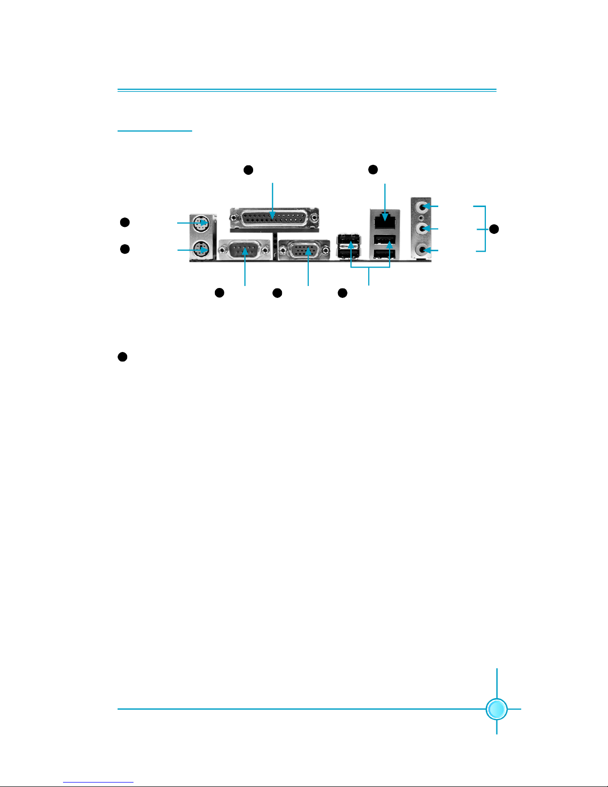
Chapter 1 Product Introduction
Serial Port
(COM1)
VGA Port
(optional)
USB 2.0 Ports (optional)
PS/2 Mouse
Connector
Parallel Port
(Printer Port)
LAN Port
Line-in jack
Line-out jack
Microphone
jack
1
4
5
8
PS/2 Keyboard
Connector
3
2
6
7
Line-in jack, Line-out jack, Microphone jack
Use the three audio ports to connect audio devices. The Line-in jack is for a
tape player or other audio sources. The Line-out jack is for a headphone or a
speaker. The Microphone jack is for a microphone. In 6-Channel mode, the
function of the three jacks becomes Rear Speaker Out, Front Speaker Out and
Center/Subwoofer Speaker respectively.
8
Rear I/O Ports

Chapter 1 Product Introduction
6
This chapter introduces the hardware installation process, in-
cluding the installation of the CPU, memory, power supply,
slots and pin headers, and the mounting of jumpers. Cau-
tion should be exercised during the installation of these
modules. Please refer to the motherboard layout prior to any
installation and read the contents in this chapter carefully.
This chapter includes the following information:
v CPU
v Memory
v Power supply
v Other Connectors
v Expansion Slots
v Jumpers
Chapter
2
2
Chapter 2 Installation Instructions
7
CPU
This motherboard supports single processor in an LGA775 package. It also
supports Hyper-Threading technology and FSB Dynamic Bus Inversion (DBI).
For the detailed CPU vendor list qualified on this motherboard, please visit
the website: h
ttp://www.foxconnchannel.com
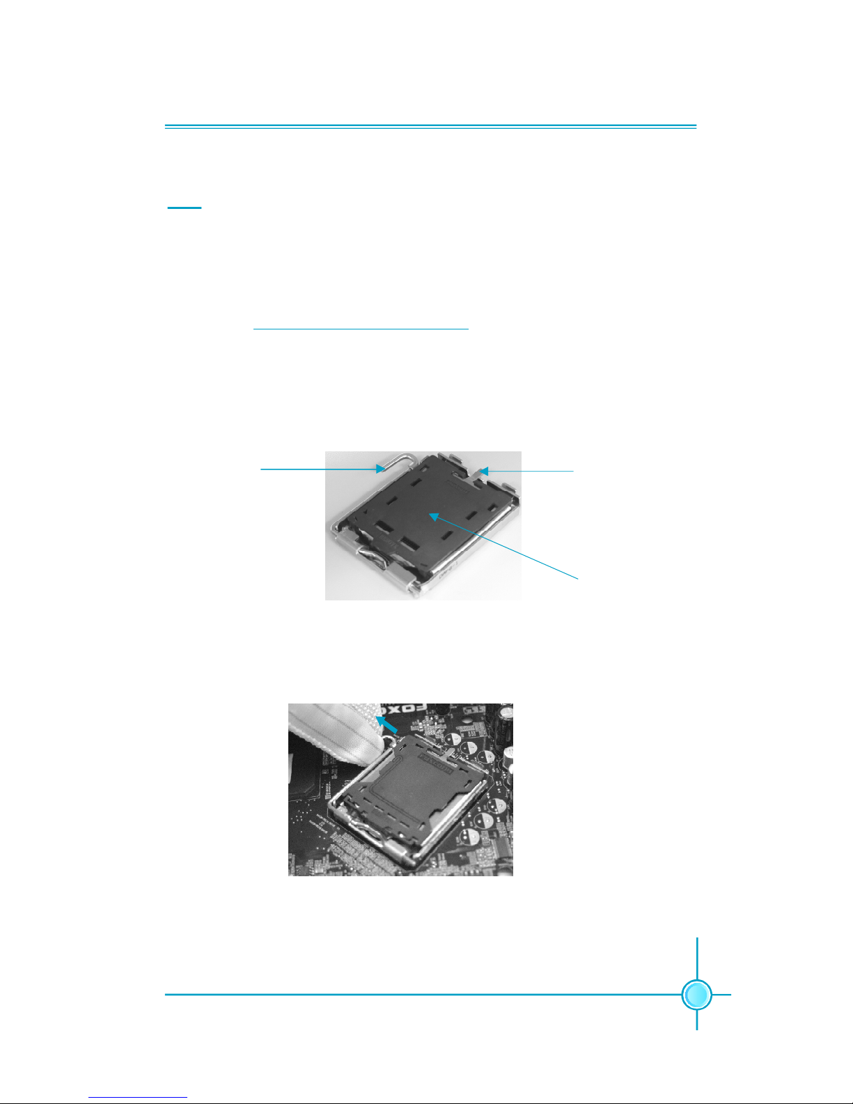
Installation of CPU
Below is the CPU socket illustration. Follow these procedures to install a CPU.
Load lever
Load plate
Protective cover
1. Use thumb and forefinger to hold the hook of the load lever and pull the lever
down and away from socket to unlock it. Lift the load lever.
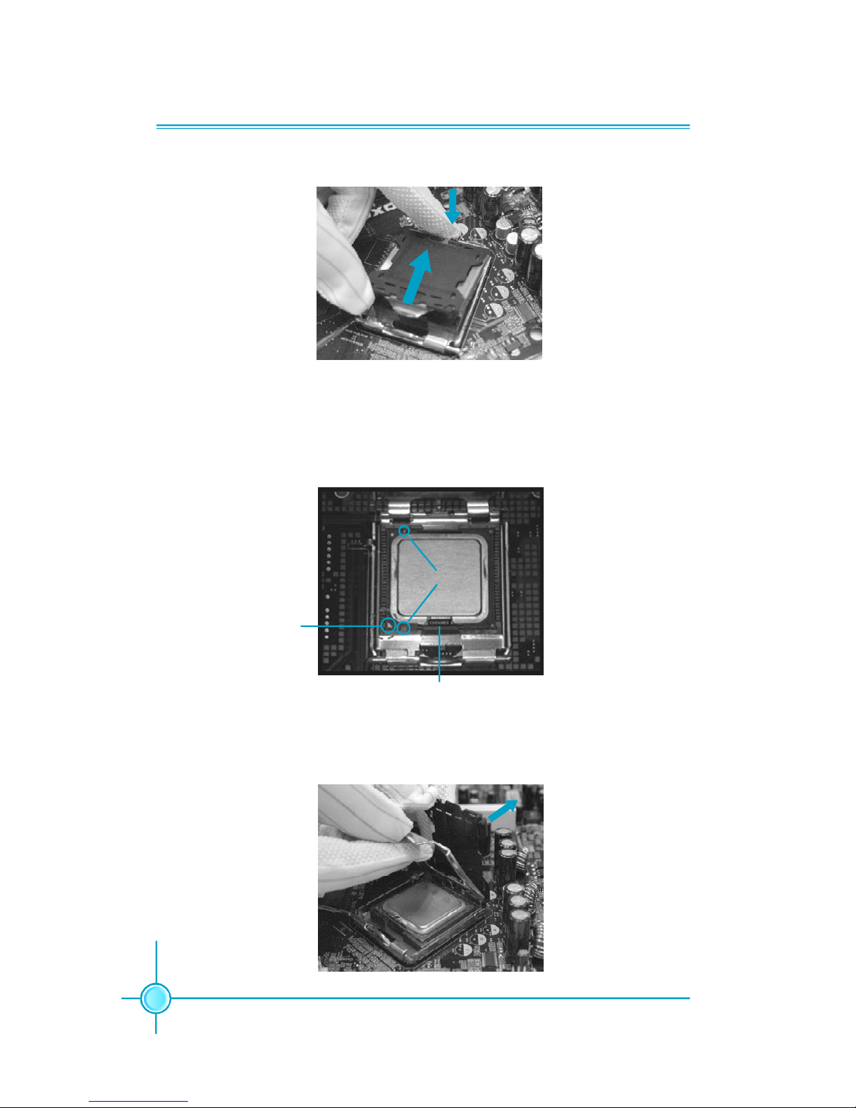
2. Push down the rear tab with your forefinger to bring the front end of the load
plate up slightly. Open the load plate with thumb. Be careful not to touch the
contacts.
Chapter 2 Installation Instructions
8
3. Hold CPU with thumb and forefinger. Ensure fingers align to socket cutouts.
Match the CPU triangle marker to Pin 1 position as shown below. The alignment
key also provides the orientation directed function. Lower the CPU straight down
without tilting or sliding the CPU in the socket.
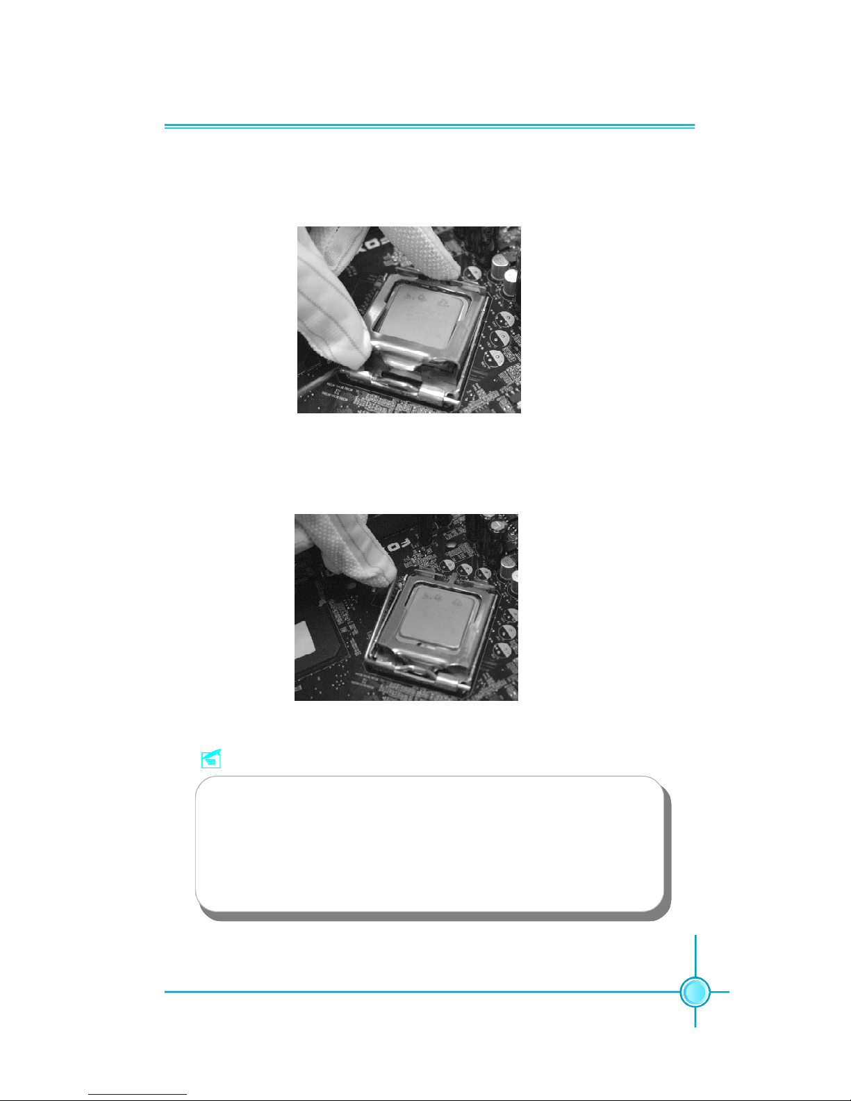
4. After installing the CPU, remove the protective cover from load plate. The
protective cover is used to protect the contacts of the socket. Do not discard the
protective cover. Always replace the socket cover if the CPU is removed from the
socket.
Alignment Key
Socket Cutouts
Pin 1 position
Chapter 2 Installation Instructions
9
5. Close the load plate, and slightly push down the tongue side.
6. Lower the lever and lock it to the load plate, then the CPU is locked completely.
Note :
Excessive temperatures will severely damage the CPU and
system. Therefore, you should install CPU cooling fan and make
sure that the cooling fan works normally at all times in order to
prevent overheating and damaging to the CPU. Please refer to your
CPU fan user guide to install it properly.
Chapter 2 Installation Instructions
10
Memory
This motherboard includes two 184-pin slots with 2.6V for DDR and two 240-pin
slots (optional) with 1.8V for DDR2. DIMM1 and DIMM3 slots support 256 Mb,
512 Mb and 1 Gb DDR2 technologies for x8 and x16 devices; DIMM2 and DIMM4
slots support 256 Mb, 512 Mb and 1 Gb DDR technologies for x8 and x16 devices.
You must install at least one memory bank to ensure normal operation.
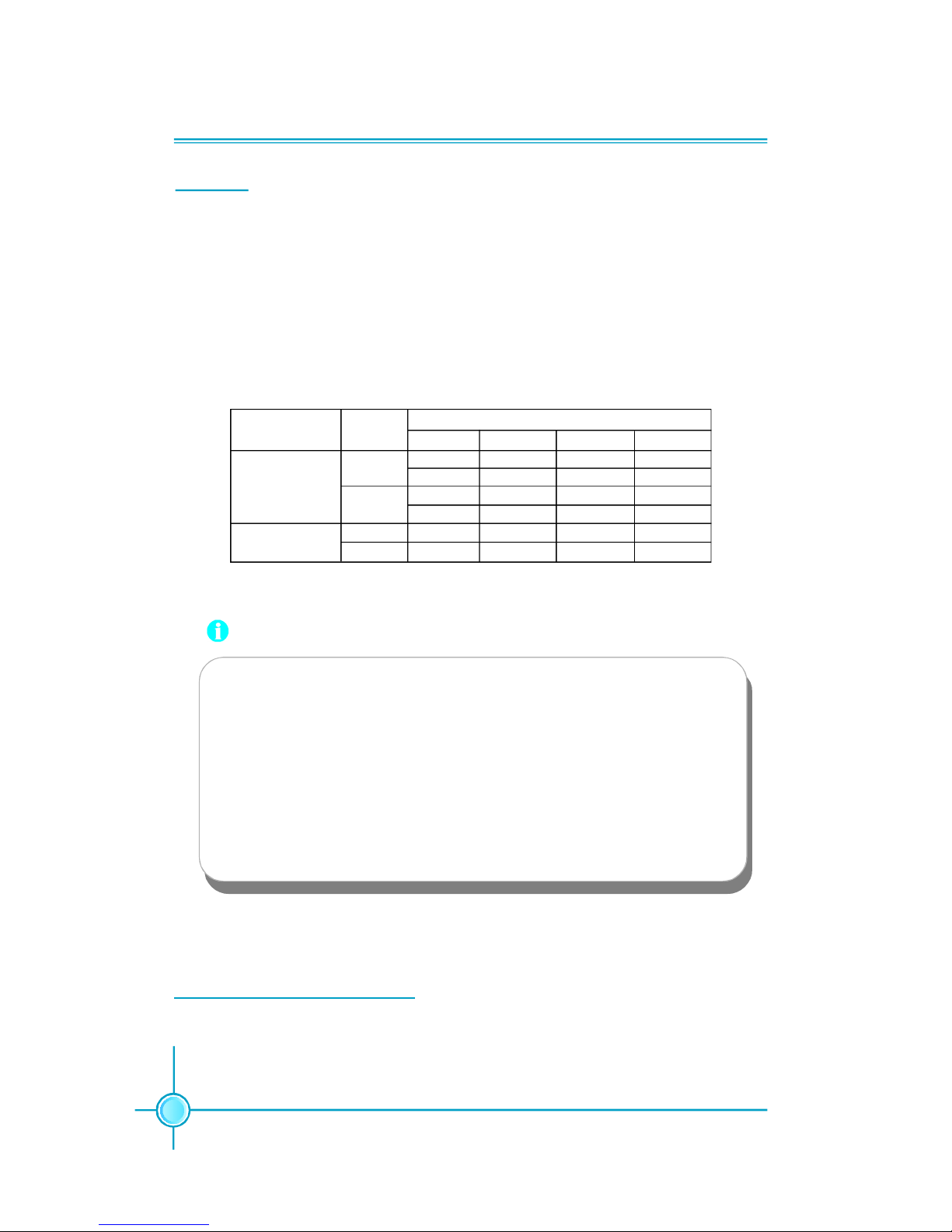
Memory Configuration Table
Use any of the recommended configurations in the following table
DIMM1 DIMM2 DIMM3 DIMM4
x Populated x x
x x x Populated
Populated x x x
x x Populated x
x Populated x Populated
Populated x Populated x
Channel Mode
Single-
Channel
Dual-Channel
DIMMDDR
Type
DDR
DDR2
DDR
DDR2
Attention:
1.Before you install memory modules, please make sure that all
DIMMsin one system are of the same type (e.g. all DDR or all
DDR2, not mixed).
2.If DDR and DDR2 memory banks are installed simultaneously
or all four sockets are populated with DIMMs, the buzzer will alarm
for memory error warning and power-on failure may result. But
in this case, it can not cause any damage to your motherboard
and memory banks since an exclusive protection circuit is specially designed for it.
For the latest memory modules support list, please visit the website:
h
ttp://www.foxconnchannel.com
Chapter 2 Installation Instructions
11
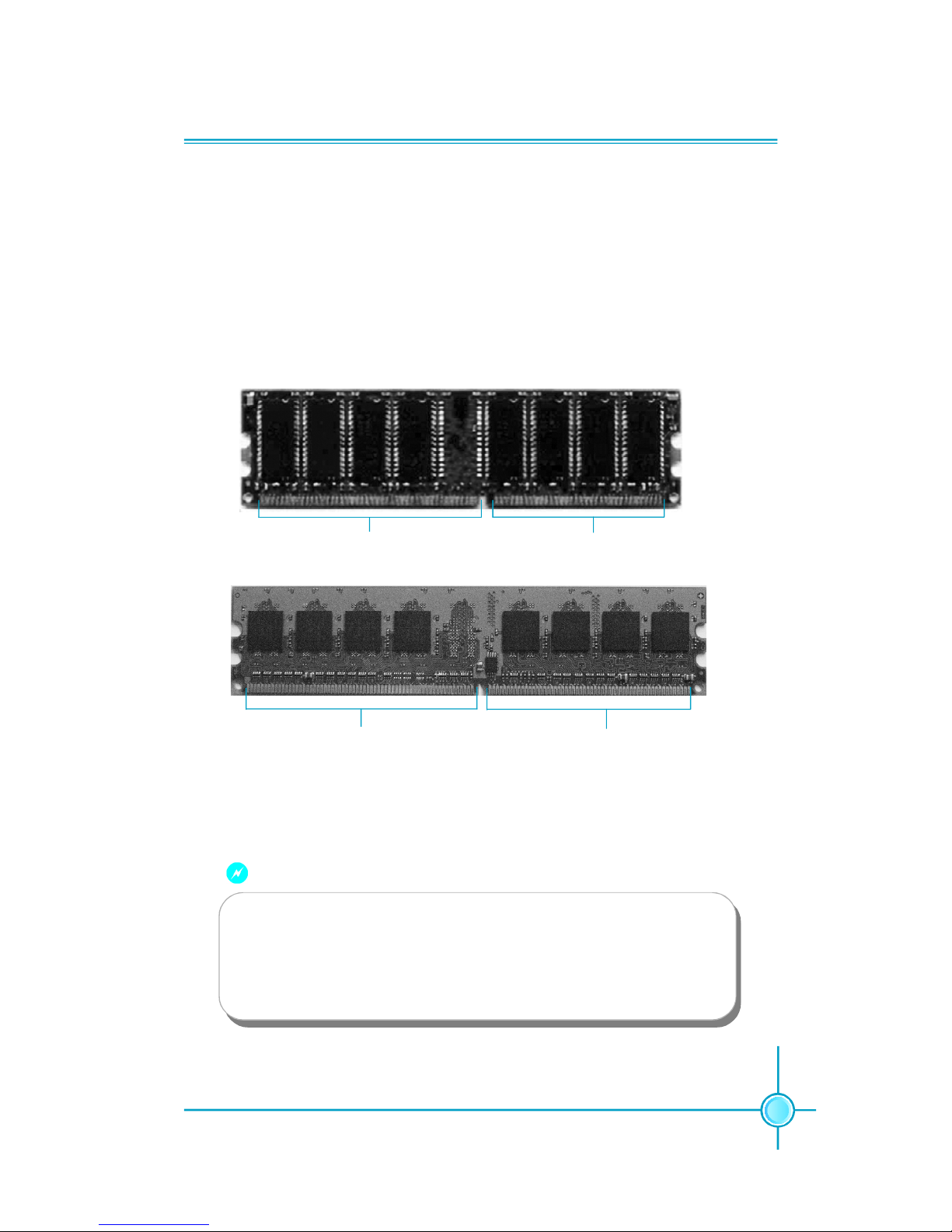
Installation of DDR/DDR2 Memory
1.There is only one gap in the middle of the DIMM slot, and the memory
module can be fixed in one direction only. Unlock a DIMM slot by pressing the
module clips outward.
2.Align the memory module to the DIMM slot, and insert the module vertically
into the DIMM slot.
3.The plastic clips at both sides of the DIMM slot will lock automatically.
Warning :
104 Pins
80 Pins
128 Pins
112 Pins
DDR
memory
DDR2
memory
Be sure to unplug the AC power supply before adding or removing
expansion cards or other system peripherals, especially the
memory devices, otherwise your motherboard or the system
memory might be seriously damaged.
Chapter 2 Installation Instructions
12
Power Supply
This motherboard uses an ATX power supply. In order to avoid damaging any
devices, make sure that they have been installed properly prior to connecting
the power supply.
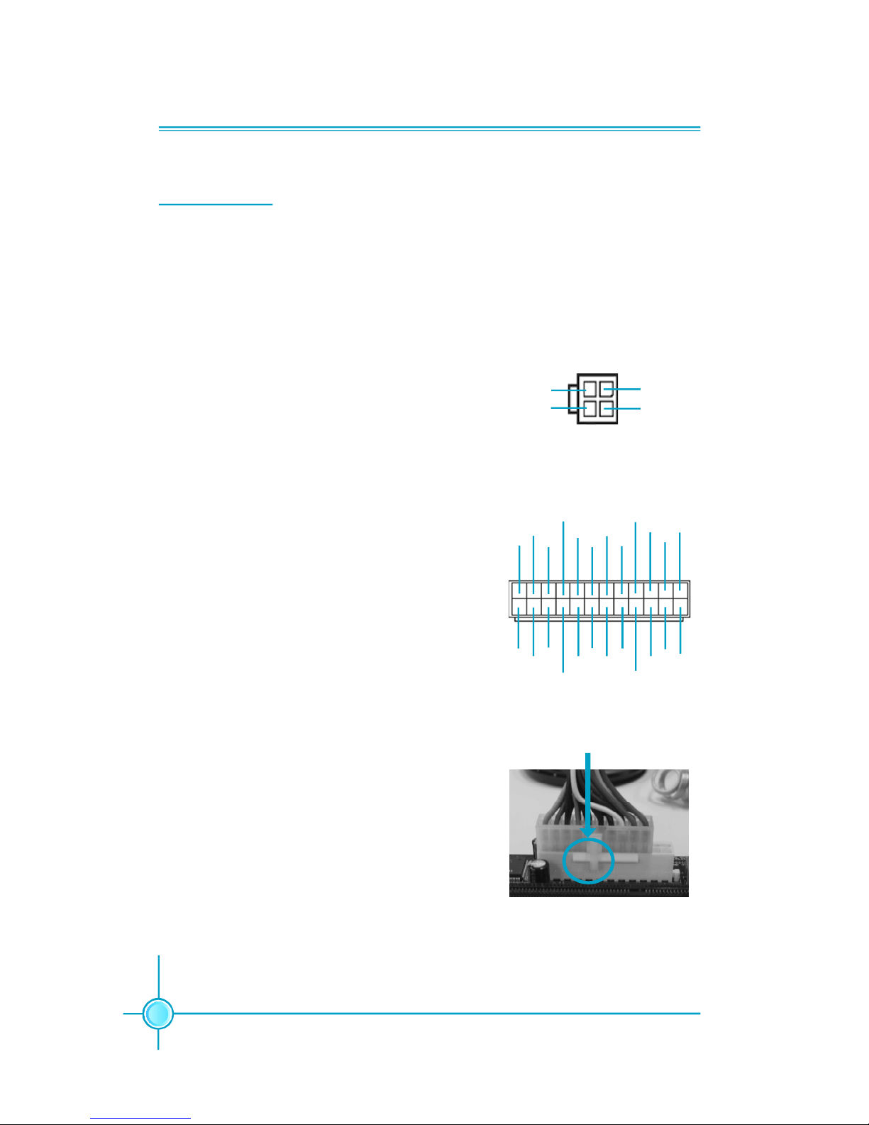
Note: We strongly recommended you use 24-
pin power supply. If you want to use 20-pin
power supply, you need to align the ATX power
connector according to the right picture.
Align the connector
24-pin ATX power connector: PWR1
PWR1 is the ATX power supply connector. Make
sure that the power supply cable and pins are
properly aligned with the connector on the
motherboard. Firmly plug the power supply cable
into the connector and make sure it is secure.
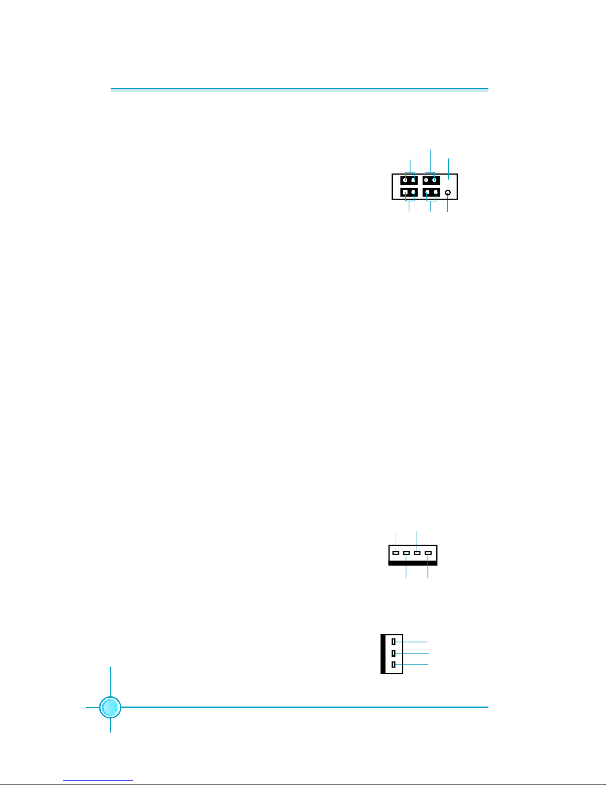
4-pin ATX_12V Power Connector: PWR2
The ATX power supply connects to PWR2 and
provides power to the CPU.
4-pin ATX_12V power connector
12V
GND
12V
3
1
4 2
GND
24
24-pin ATX power connector
13
+3.3V
-12V
NC
+5V GND
GND
GND
PSON
+5V
+3.3V
GND
+12V
GND
+5V_AUX
+3.3V
+5V
+12V
GND
+5V
+3.3V
GND GND
+5V
12
PWROK
1
Chapter 2 Installation Instructions
13
Other Connectors
This motherboard includes connectors for FDD, IDE HDD, Serial ATA, USB,
IR module, and others.
FDD connector: FLOPPY
This motherboard includes a standard FDD connector, supporting 360 K, 720 K,
1.2 M, 1.44 M, and 2.88 M FDDs.
HDD connector: PIDE
The connector supports the provided Ultra DMA 100/66/33 IDE hard disk
ribbon cable. Connect the cable’s blue connector to the IDE connector, then
connect the gray connector to the Ultra DMA 100/66/33 slave device (hard disk
drive) and the black connector to the Ultra DMA 100/66/33 master device.
Attention:
Ribbon cables are directional, therefore, make sure to always con-
nect with the cable on the same side as pin 1 of the PIDE or FDD
connector on the motherboard.
Chapter 2 Installation Instructions
14
Front Panel Connector: FP1
This motherboard includes one connector for connect-
ing the front panel switch and LED indicators.
IDE LED Connector (HD-LED)
The connector connects to the case’s IDE indicator
LED indicating the activity status of hard disks.
Reset Switch (RESET)
Attach the connector to the Reset switch on the front
panel of the case; the system will restart when the
switch is pressed.
Power LED Connector (PWRLED)
Attach the connector to the power LED on the front
panel of the case. The Power LED indicates the
system’s status. When the system is in S0 status, the
LED is on. When the system is in S1 status, the LED
is blink; When the system is in S3, S4, S5 status, the
LED is off.
Power Switch Connector (PWRSW)
Attach the connector to the power button of the case.
Pushing this switch allows the system to be turned on
and off rather than using the power supply button.
FP1
NCHD-LED
PWRLED
PWRSW
Empty
Fan Connectors: CPU_FAN, SYS_ FAN
The fan speed of CPU_FAN and SYS_FAN can be
detected and viewed in “PC Health Status” section of
the CMOS Setup. These fans will be automatically
turned off after the system enters S3, S4 and S5 mode.
Plug the CPU cooling fan cable into the 4-pin CPU
FAN power supply on the motherboard. Connect the
case cooling fan connector to SYS_FAN.
SYS_FAN
+12V
GROUND
SENSE
1
CPU_FAN
SENSE
POWER
GROUND
1
CONTROL
+ -
+ -
1
RESET
Chapter 2 Installation Instructions
15
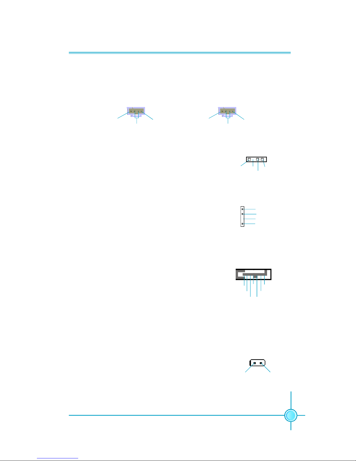
Audio Connectors: CD_IN, AUX_IN
CD_IN, AUX_IN is Sony standard CD audio connectors, it can be connected to a
CD-ROM drive through a CD audio cable.
CD_IN
1
CD_R
GND
CD_L
AUX_IN
1
AUX_L
GND
AUX_R
Speaker Connector: SPEAKER (optional)
The speaker connector is used to connect speaker of
the chassis.
SPDIF Out Connector: SPDIF_OUT (optional)
The S/PDIF out connector is capable of providing digi-
tal audio to external speakers or compressed AC3
data to an external Dolby digital decoder.
Note:The empty pin of SPDIF cable should be aligned
to empty pin of SPDIF out connector.
1
SPDIF_OUT
SPDIF_OUT
5V_SYS
GND
Empty
S-ATA Connectors: SATA1, SATA2, SATA3, SATA4
The S-ATA connector is used to connect the S-ATA de-
vice to the motherboard. These connectors support
the thin Serial ATA cables for primary storage devices.
The current Serial ATA interface allows up to 150MB/s
data transfer rate.
SPEAKER
1
SPKJ
EmptySPK
NC
1
SATA 1/SATA 2/
SATA 3/SATA 4
GND
GND GND
RX+
RX-TX-
TX+
Chassis Intruder Connector: INTR
The connector connects to the chassis security switch
on the case. The system can detect the chasis intrusion through the status of this connector. If the connector has been closed once, the system will send a
message. To utilize this function, set “Case Open Warning” to “Enabled” in the “PC Health Status” section of
the CMOS Setup. Save and exit, then boot the operating
system once to make sure this function takes effect.
INTR
1 INTRUDERJ 2 GND
Chapter 2 Installation Instructions
16
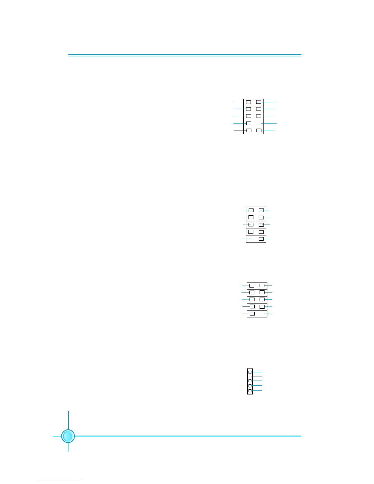
Audio Connector: F_AUDIO
The audio interface provides two kinds of audio output choices: the Front Audio, the Rear
Audio. Their priority is sequenced from high to
low (Front Audio to Rear Audio). If headphones
are plugged into the front panel of the chassis
(using the Front Audio), then the Line-out (Rear
Audio) on the rear panel will not work. If you do
not want to use the Front Audio, pin 5 and 6,
pin9 and 10 must be short, and then the signal
will be sent to the rear audio port.
Besides four USB ports on the rear panel, the
series of motherboards also have two or three
10-pin connectors on board which may connect
to front panel USB cable(optional) to provide
additional four USB ports.
F_AUDIO
AUD_OUT-L
NA
MIC_IN
MIC_PWR
AUD_OUT-R
MIC_GND
+5VA
AUD_RET-R
AUD_RET-L
Empty
1
USB Connectors: F_USB1, F_USB2, F_USB3 (optional)
1
5V_DUAL
F_USB1/2/3
D-
D+
D-
GND
GND
D+
NC
Empty
5V_DUAL
Addtional COM Connector: COM2
This motherboard provides an additional serial
COM connector for your machine.
Connect one side of a switching cable to the
connector, then attach the serial COM device
to the other side of the cable.
SOUT
GND
RLSD
RI#
DTR#
DSR#
SIN
9
10
1 2
CTS#
RTS#
COM2
Empty
IrDA Connector: IR
This connector supports wireless transmit-
ting and receiving device. Before using this
function, configure the settings of IR Mode
from the “Integrated Peripherals” section of
the CMOS Setup.
IR
1
+5V
GND
IRRX
IRTX
Empty

Chapter 2 Installation Instructions
17
Expansion Slots
This motherboard includes three 32-bit Master PCI bus slots and one PCI Ex-
press x 16 slot (only for 915G/P/PL7MH series) or F.G.E.II slot (only for 915GV/
GL/910GL7MH series).
PCI Slots
The expansion cards can be installed in the three PCI slots. When you install or
take out such cards, you must make sure that the power plug has been
pulled out. Please read carefully the instructions provided for such cards, and
install and set the necessary hardware and software for such cards, such as
the jumper or BIOS setup.
PCI Express Slot
PCI Express will offer the following design advantages over the PCI and AGP
interface:
-Compatible with existing PCI drivers and software and Operating Systems.
-High Bandwidth per Pin. Low overhead. Low latency.
-PCI Express supports a raw bit-rate of 2.5 Gb/s on the data pins. This
results in a real bandwidth per pair of 250 MB/s.
-A point to point connection, allows each device to have a dedicated connec-
tion without sharing bandwidth.
-Ability to comprehend different data structure.
-Low power consumption and power management features
PCI Express will take two forms, x16 and x1 PCI Express slots. Whereas the x16
slot is reserved for graphic/video cards, the x1 slot is designed to accommo-
date less bandwidth-intensive cards, such as a modem or LAN card.
The difference in bandwidth between the x16 and x1 slots is notable to be sure,
with the x16 slot pushing 4GB/sec (8GB/sec concurrent) of bandwidth, and the
x1 PCI Express slot offering 250MB/sec.
Warning:
If a performance graphics card was installed into 16X PCI Express slot,
2 x 12 pin power supply was strongly recommended.
Chapter 2 Installation Instructions
18
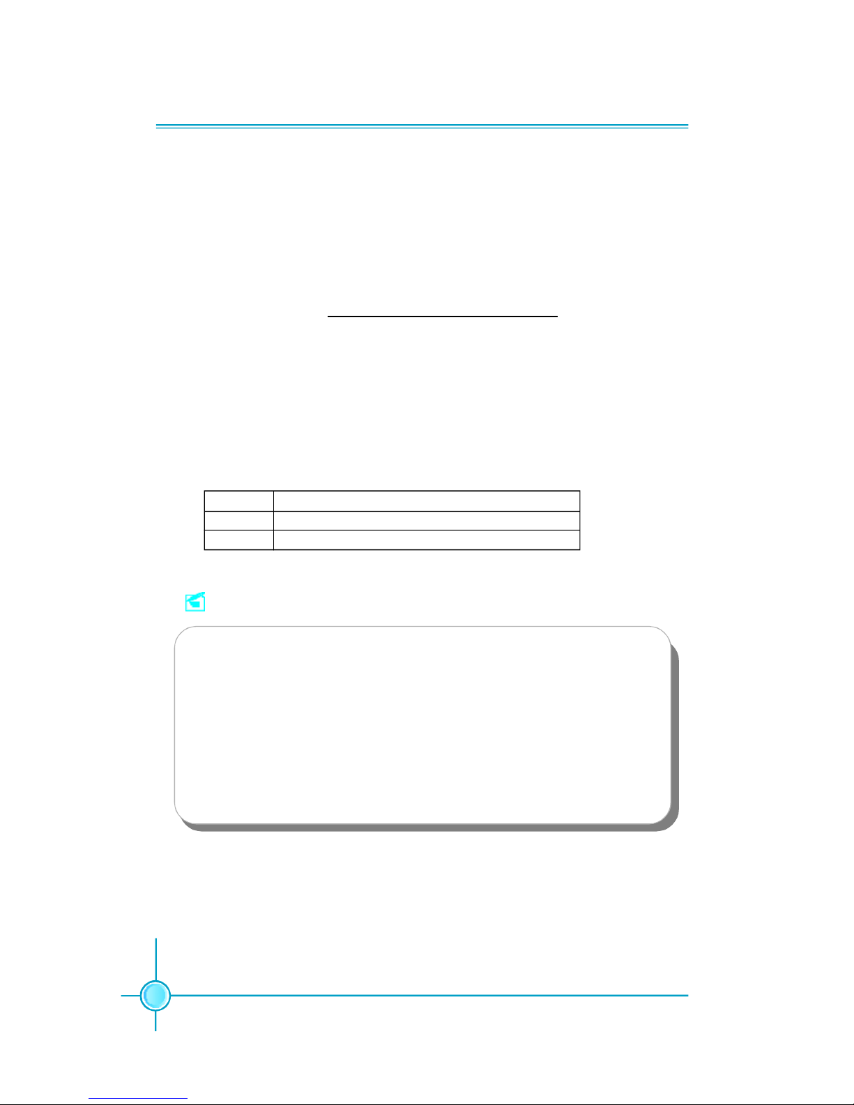
F.G.E. II Slot
The F.G.E.II (Foxconn Graphics Extension II) slot is a special design that pro-
vides an extended graphics interface for PCI Express 16X VGA cards.
Note:For the latest PCI Express 16X VGA cards support list, please visit
Foxconn website for details.
Foxconn website: h
ttp://www.foxconnchannel.com
With F.G.E.II technology, This motherboard can enjoy Facile Dual Monitor
feature, which provides an enhanced productivity feature for business
workers, programmer and etc..
Facile Dual Monitor Feature Support Matrix Table
1 PCI Express X16 (for 915G)+ Onboard VGA
2 Onboard VGA (for 915GL/GV/910GL) + F.G.E. II
ConfigurationMatrix
Note
To install the system with an add-on PCI Express VGA card, please make
sure to install the driver of the add-on PCI Express VGA card before you
install the onboard VGA driver. If the onboard VGA dirver has already been
installed prior to installing the add-on PCI Express VGA card, the system
will automatically set the onboard VGA as the primary graphics adapter. In
this case, if you want to install the add-on PCI Express VGA card, you need
to remove the onboard VGA driver first, and then install the add-on PCI
Express VGA card and its driver.
 Loading...