

Page 1

Statement:
This manual is the intellectual property of Foxconn, Inc. Although the information
in this manual may be changed or modified at any time, Foxconn does not
obligate itself to inform the user of these changes. Additionally, Foxconn does
not accept responsibility for any direct or indirect accident relating with the use
of this manual.
Trademark:
All trademarks are the property of their respective owners.
®
Intel
and Pentium® are registered trademarks of Intel Corporation.
PS/2 and OS/2 are the registered trademarks of IBM, Inc.
Windows® 95/98/2000/NT/XP/Me is the registered trademark of Microsoft.
®
is the registered trademark of Award, Inc.
Award
Version:
User manual V1.0 in English for 875A02 series
P/N:91-181-U75-10-00
Symbol description:
Note: refers to important information that can help you use motherboard better.
Attention: indicates that it may damage hardware or cause data loss, and tells
you how to avoid such problems.
Warning: means that a potential risk of property damage or physical injury exists.
More information:
If you want more information about our products, please visit Foxconn’s
website:
Foxconn:
875A02-English preface-V1.0-010604.p65 2004-4-12, 13:391
www.foxconnchannel.com
Page 2

Item Checklist:
Thanks for your purchasing Foxconn’s 875A02 series motherboard. Please check
the package; if there are missing or damaged items, contact your distributor as
soon as possible.
875A02 series motherboard (x1)
Foxconn Utility CD (x1)
User manual (x1)
SATA RAID user manual (x1)
IDE ribbon cable (x1)
Floppy ribbon cable (x1)
I/O shield (x1)
S-ATA signal cable (x1) (optional)
S-ATA power cable (x1) (optional)
SPDIF cable (x1) (optional)
USB 2.0 cable (x1) (optional)
Intel ICH5R RAID Installation Support Disk (x1)
Silicon 3112A RAID Installation Support Disk (x1)
875A02-English preface-V1.0-010604.p65 2004-4-12, 13:392
Page 3

Declaration of conformity
HON HAI PRECISION INDUSTRY COMPANY LTD
66 , CHUNG SHAN RD., TU-CHENG INDUSTRIAL DISTRICT,
TAIPEI HSIEN, TAIWAN, R.O.C.
declares that the product
Mainboard
875A02 series
is in conformity with
(reference to the specification under which conformity is declared in
accordance with 89/336 EEC-EMC Directive)
EN 55022/A1: 2000 Limits and methods of measurements of radio disturbance
characteristics of information technology equipment
EN 61000-3-2/A14:2000 Electromagnetic compatibility (EMC)
Part 3: Limits
Section 2: Limits for harmonic current emissions
(equipment input current <= 16A per phase)
EN 61000-3-3/A1:2001 Electromagnetic compatibility (EMC)
Part 3: Limits
Section 2: Limits of voltage fluctuations and flicker in lowvoltage supply systems for equipment with rated current
<= 16A
EN 55024/A1:2001 Information technology equipment-Immunity characteristics
limits and methods of measurement
Signature : Place / Date : TAIPEI/2003
Printed Name : James Liang Position/ Title : Assistant President
875A02-English preface-V1.0-010604.p65 2004-4-12, 13:393
Page 4

Declaration of conformity
Trade Name: FOXCONN
Model Name:
Responsible Party: PCE Industry Inc.
Address: 458 E. Lambert Rd.
Telephone: 714-738-8868
Facsimile: 714-738-8838
Equipment Classification: FCC Class B Subassembly
Type of Product: Mainboard
Manufacturer: HON HAI PRECISION INDUSTRY
Address: 66 , CHUNG SHAN RD., TU-CHENG
875A02
Fullerton, CA 92835
COMPANY LTD
INDUSTRIAL DISTRICT, TAIPEI HSIEN,
TAIWAN, R.O.C.
Supplementary Information:
This device complies with Part 15 of the FCC Rules. Operation is subject to the
following two conditions : (1) this device may not cause harmful interference,
and (2) this device must accept any interference received, including interfer-
ence that may cause undesired operation.
Tested to comply with FCC standards.
Signature : Date : 2003
875A02-English preface-V1.0-010604.p65 2004-4-12, 13:394
Page 5

Table of Contents
Chapter
Main Features ............................................................................................. 2
875A02 Layout ........................................................................................... 5
Chapter
CPU ........................................................................................................... 11
Memory ..................................................................................................... 16
Power Supply ........................................................................................... 21
Rear Panel Connectors ............................................................................. 22
Other Connectors ..................................................................................... 24
Expansion Slots ........................................................................................ 33
Jumpers ................................................................................................... 36
Chapter
Enter BIOS Setup ...................................................................................... 42
Main menu ................................................................................................ 42
Standard CMOS Features Setup ............................................................... 44
BIOS Features .......................................................................................... 47
Advanced BIOS Features ......................................................................... 48
Advanced Chipset Features ..................................................................... 52
Integrated Peripherals ............................................................................... 54
Power Management Setup ........................................................................ 59
PnP/PCI Configuration Setup ..................................................................... 63
PC Health Status ....................................................................................... 64
Frequency/Voltage Control ....................................................................... 65
Load Fail-Safe Defaults ............................................................................ 66
Load Optimized Defaults ........................................................................... 66
Set Supervisor/User Password ................................................................ 66
Save & Exit Setup ..................................................................................... 67
Exit Without Saving ................................................................................... 67
1
1
2
2
3
3
Product Introduction
Installation Instructions
BIOS Description
875A02-English preface-V1.0-010604.p65 2004-4-12, 13:395
Page 6

Table of Contents
Chapter
Utility CD content ...................................................................................... 69
Start to install Driver ................................................................................. 70
Install Chipset Software ............................................................................ 71
Install IAA-RAID (optional) ........................................................................ 72
Install USB2.0 Driver ................................................................................. 73
Install LAN Driver (For Realtek 10/100/1000M LAN) .................................. 74
Install and Use 4- or 6- Channel Audio Function ....................................... 75
Install Sil3112 SATARaid............................................................................ 81
Install DirectX ............................................................................................ 82
Install Norton
Chapter
SuperStep ................................................................................................ 85
SuperLogo ................................................................................................ 88
SuperUpdate ............................................................................................ 90
Chapter
SuperSpeed ............................................................................................. 97
SuperBoot ................................................................................................ 99
SuperBIOS-Protect ................................................................................. 100
SuperRecovery ...................................................................................... 101
4
4
Internet Security 2004 ....................................................... 83
5
5
6
6
Driver CD Introduction
Directions for Bundled Software
Special BIOS Feature
875A02-English preface-V1.0-010604.p65 2004-4-12, 13:396
Page 7
Warning:
1. Attach the CPU and heatsink using silica gel to ensure full contact.
2. It is suggested to select high-quality, certified fans in order to avoid
damage to the motherboard and CPU due high temperature.
3. Never turn on the machine if the CPU fan is not properly installed.
4. Ensure that the DC power supply is turned off before inserting or re
moving expansion cards or other peripherals, especially when you
insert or remove a memory module. Failure to switch off the DC
power supply may result in serious damage to your system or memory
module.
Warning:
We cannot guarantee that your system will operate normally while
over-clocked. Normal operation depends on the over-clock capacity
of your device.
Note:
Since BIOS programs are upgraded from time to time, the BIOS
description in this manual is just for reference. We do not guarantee
that the content of this manual will remain consistent with the actual BIOS version at any given time in the future.
Note:
The pictures of objects used in this manual are just for your reference.
Please refer to the physical motherboard.
875A02-English preface-V1.0-010604.p65 2004-4-12, 13:397
Page 8

This page is intentionally left blank
875A02-English preface-V1.0-010604.p65 2004-4-12, 13:398
Page 9

Chapter
Thank you for buying Foxconn’s 875A02 series
motherboard. This series of motherboard is one of our
new products, and offers superior performance, reliability
and quality, at a reasonable price. This motherboard
adopts the advanced Intel ® 875P+ICH5R chipset, provid-
ing users a computer platform with a high integration-com-
patibility-performance price ratio.
This chapter includes the following information:
1
1
Motherboard Features
875A02 Layout
Page 10

Chapter 1 Product Introduction
Main Features
Size:
ATX form factor of 12” x 9.6”
Microprocessor:
Supports Intel
processors
Supports Intel
Supports FSB at 400MHz/533MHz/800MHz
Supports Hyper-Threading technology
Chipset:
®
Intel
Chipset: Intel® 875P (NorthBridge) +ICH5R (SouthBridge)
System Memory:
Provides four 184-pin DDR DIMM Sockets
Supports for ECC (Error Checking and Correcting) and non-ECC memory
Supports for PC3200/2700/2100
Supports for 128/256/512Mb/1Gb technology up to 4GB
Supports Dual-channel DDR
®
Pentium®4 Socket 478 (Willamette/Northwood/Prescott)
®
Celeron® Socket 478 (Willamette/Northwood) processors
Attention:
1. Use the same memory modules for Dual-Channel.
2. The memory operating frequency is 320MHz while FSB800 CPU
works with DDR333.
USB 2.0 Port:
Supports hot-plug
Eight USB 2.0 ports (four rear panel ports, two onboard USB headers
providing four extra ports)
Supports wake-up from S1 and S3 mode
Supports USB 2.0 Protocol up to 480Mbps transmission rate
2
875A02 User Manual
Page 11
Chapter 1 Product Introduction
Onboard Serial ATA:
150MBps transfer rate
Supports four S-ATA devices, such as HDD, etc.
Supports Raid0, Raid1 (SATA1/2 supported by ICH5R (SouthBridge), SATA3/4
supported by Silicon 3112A Raid controller)
Attention:
If you want to use Raid0 or Raid1 function, please use the same
type SATA HDDs to SATA 1,2 or SATA 3,4 connectors
Onboard 1394 (Optional):
Supports hot-plug
With rate of transmission at 400Mbps
Self-configured addressing
Supports two independent 1394 units (1 rear, 1 front) synchronously at most,
such as HDD, CD-ROM
Onboard LAN (Optional):
LAN interface built-in onboard
10M/100M/1G LAN interface
Onboard Audio:
AC’ 97 2.2 Specification Compliant
Supports S/PDIF output
Onboard Line-in jack, Microphone-in jack, Line-out jack
Supports 5.1 channels audio (setting via software)
BIOS:
Licensed advanced AWARD (Phoenix) BIOS, supports flash ROM, Plug-and-
Play
Supports IDE CD-ROM, SCSI HDD or USB device boot up
Green Function:
Supports ACPI (Advanced Configuration and Power Interface)
Supports five system modes-S0 (normal), S1 (power on suspend), S3
(suspend to RAM), S4 (suspend to disk-depends on OS), and S5 (soft-off)
875A02 User Manual
3
Page 12

Chapter 1 Product Introduction
Expansion Slots:
5 PCI slots
1 AGP slot
AGP 8X support:
AGP 8X (AGP 3.0) is the VGA interface specification that enabled enhanced
graphics performance with high handwidth speeds up to 2.12 GB/s.
Advanced Features:
PCI 2.3 Specification Compliant
Supports Windows98/2000/ME/XP soft-off
Supports Wake-on-LAN function
Supports PC Health function (capable of monitoring system voltage, CPU,
system temperature, and fan speed)
Intel® Performance Acceleration Technology (PAT) :
The Intel
level performance by optimizing memory access between CPU and system
memory on 800-MHz FSB and Dual Channel DDR400 configuration.
®
Performance Acceleration Technology deliver additional system-
Attention:
Enabling the functionality of Hyper-Threading Technology for your com-
puter system requires all of the following platform components:
CPU: An Intel® Pentium® 4 Processor with HT Technology
Chipset: An Intel® Chipset that supports HT Technology
BIOS: a BIOS that supports HT Technology and has it enabled
O/S: An operating system that has optimizations for HT Technology
For more information go www.intel.com/info/hyperthreading
4
875A02 User Manual
Page 13
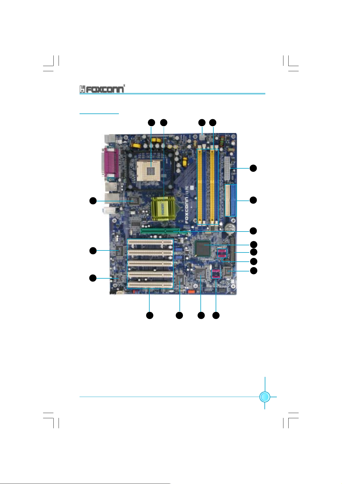
875A02 Layout
Chapter 1 Product Introduction
18
17
16
2 41
3
5
6
7
8
9
10
11
1415
875A02 User Manual
13 12
5
Page 14

Chapter 1 Product Introduction
CPU socket
1
A 478-pin surface mount, Zero Insertion Force (ZIF) Socket for the intel
Pentium® 4 processor (and Intel’s future Prescott CPU) Supports 800/533/
400 MHz system bus and allows up to 6.4GB/s data transfer rates.
2
North bridge controller
The Intel® 875P Memory Controller Hub(MCH) provides the processor
interface with 800/533/400 MHz frequency, system memory interface at 400/
333/266MHz operation, and 1.5V AGP interface that supports AGP 3.0
specification including 8X Fast Write protocol.
3
ATX 12V connector
This power connector connects the 4-pin 12V plug from the ATX 12V power
supply.
4
DDR DIMM sockets
These four 184-pin DIMM sockets support up to 4GB system memory using
unbuffered ECC and Non-ECC PC3200/2700/2100 DDR DIMMs.
®
5
ATX power connector
This 20-pin connector connects to an ATX power supply. The power supply
must have at least 1A on the +5V standby lead (+5VSB).
6
IDE connectors
These 2-channel bus master IDE connectors support Ultra DMA 100/66/33,
PIO Modes 3 & 4 IDE devices. Both the primary (blue)and secondary (white)
connectors are slotted to prevent incorrect insertion of the IDE ribbon cable.
7
AGP slot
This Accelerated Graphics Port (AGP) slot supports 1.5V AGP8X mode Graphic
card for 3D graphical applications.
6
875A02 User Manual
Page 15

Chapter 1 Product Introduction
8
South bridge
The Intel ICH5R are subsystem that integrate various I/O functions including
2-channel ATA100 bus master IDE controller, SATA RAID controller (Supported
by ICH5R only), up to eight USB 2.0/1.1 ports, I/O APIC, AC’97 2.2 interface,
and PCI 2.3 interface.
9
Floppy disk connector
This connector accommodates the provided ribbon cable for the floppy disk
drive. One side of the connector is slotted to prevent incorrect insertion of the
floppy disk cable.
10
SATA 1/2 connectors
These two 7-pin connectors of ICH5R accommodate the thin cables for Serial
ATA devices.
11
Flash ROM
This 4Mb flash ROM contains the programmable BIOS program.
12
SATA 3/4 connectors
These two 7-pin connectors of Sil3112A accommodate the thin cables for
Serial ATA devices.
SATA 3/4 controller
13
The Silicon Image Sil3112A is a single-chip solution for a PCI to Serial ATA
controller. It accepts host commands through the PCI bus, processes them
and transfers data between the host and Serial ATA devices. It can be used to
control SATA3 and SATA4 two independent Serial ATA channels. Each channel
has its own Serial ATA bus and will support one Serial ATA device. The Sil3112A
supports a 32-bit 66 MHz PCI bus and the Serial ATA Generation 1 transfer
rate of 1.5 Gb/s (150 MB/s), supported Raid0, Raid1.
14
1394 controller (optional)
VT6307 is the controller for IEEE1394a on Motherboard. The VT6307 is a
complete small package single chip PCI solution at 400Mbps, low power
seamless plug and play connections to the latest IEEE 1394 enabled devices
875A02 User Manual
7
Page 16

Chapter 1 Product Introduction
15
PCI Slots
These five 32-bit PCI 2.3 expansion slots support bus master PCI cards like
SCSI or LAN cards with 133MB/s maximum throughput.
16
Audio CODEC
The ALC650 is an AC’97 CODEC that allows 6-channel audio playback. The
audio CODEC provides six DAC for 5.1 surround sound, S/PDIF output, AUX
and CD-IN, Line-in, Line-out and Speaker out.
17
1G LAN controller (Optional)
The 8110S Gigabit Ethernet is a single-chip solution for LAN on Motherboard
(LOM) applications, and supports 10/100/1000 Mbps data transfer rates.
Super I/O
18
The Winbond W83627HF Low Pin Count (LPC) interface provides the
commonly used Super I/O functionality. The chip supports a high-performance
floppy disk controller for a 360k/720K/1.44M/2.88M floppy disk drive, a multi-
mode parallel port, two serial ports, the mouse and keyboard interface and
the LPC (Low Pin Count) interface.
8
875A02 User Manual
Page 17

Chapter
This chapter introduces the hardware installation process,
including the installation of the CPU and memory. It also
addresses the connection of your power supply, use of
the rear panel connectors, connection of hard drive and
floppy drive data cables, and setting up various other
feature of the motherboard. Caution should be exercised
during the installation process. Please refer to the
motherboard layout prior to any installation and read the
contents in this chapter carefully.
This chapter includes the following information:
2
2
CPU
Memory
Power Supply
Rear Panel Connectors
Other Connectors
Expansion Slots
Jumpers
Page 18

Chapter 2 Installation Instructions
Notes:
Take note of the following precautions before you install components or change settings.
1. Use a grounded wrist strap or touch a safely grounded object,
such as an attached power supply, before handling components
to avoid damaging them due to static electricity.
2. Unplug the power cord before opening your chassis or touching
any component.
3. Hold components by their edges to avoid touching any exposed
integrated circuits (ICs).
4. Whenever you uninstall a component, place it on a grounded
anti-static pad or into the anti-static bag that it came in.
10
875A02 User Manual
Page 19
Chapter 2 Installation Instructions
CPU
This motherboard accepts Intel socket 478 processors (CPUs) with a front side
bus (FSB) of 400/533/800 MHz Processors with Hyper-Threading technology
are supported.
Attention:
The CPU pins must be properly aligned with the holes in the
socket, otherwise the CPU may be damaged.
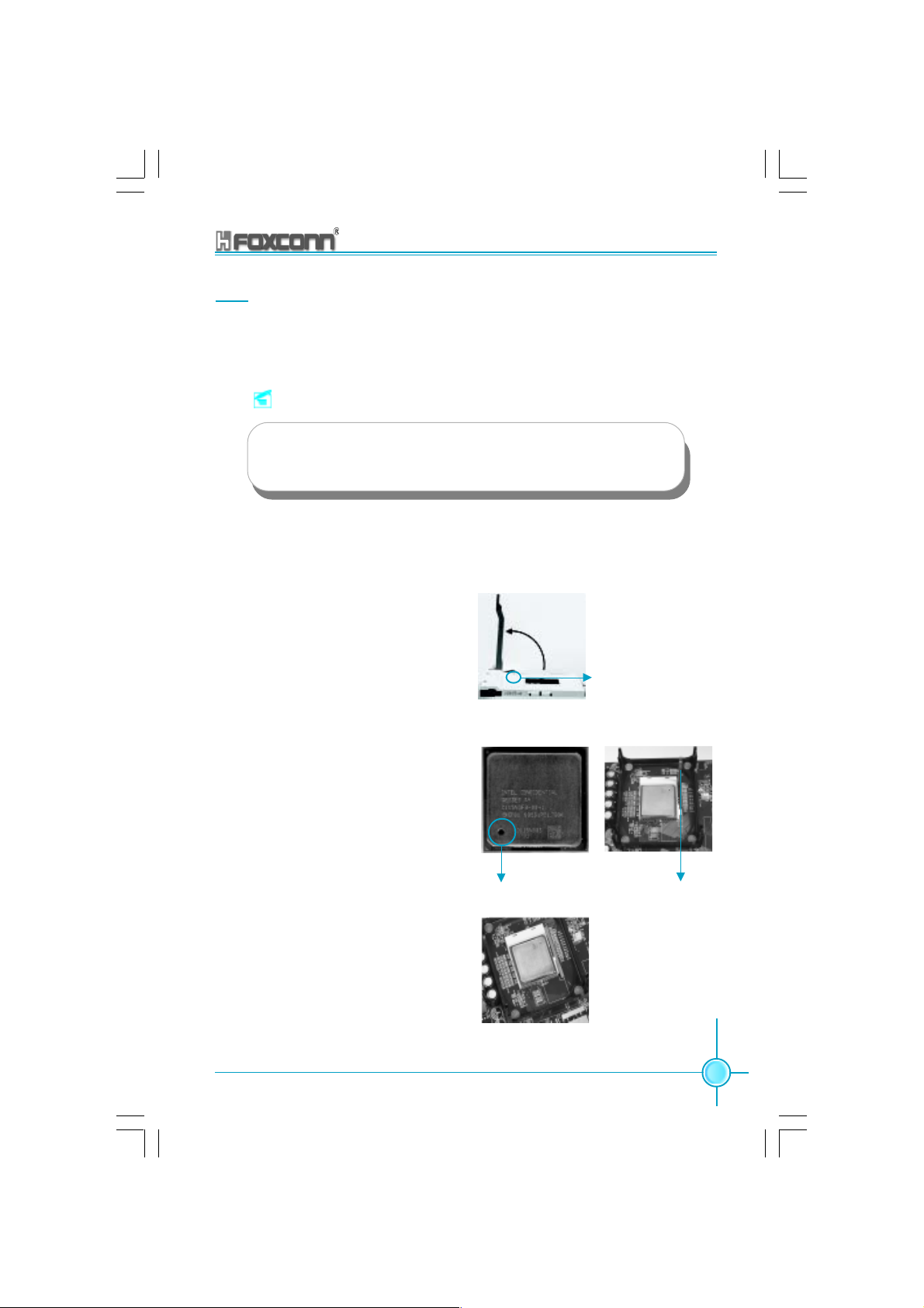
Installation of CPU
Follow these steps to install the CPU.
1. Unlock the socket by pressing the lever sideways, then lift it up to a 90
o
angle.
2. Align the cut edge to the gap in the
base of the socket. Carefully insert
the CPU into the socket until it fits in
place.
3. When the CPU is in place, press it
firmly on the socket while you push
down the socket lever to secure the
CPU. The lever clicks on the side tab
to indicate that it is locked.
Cut edge
90
o
Gap in the base
Push down the socket
lever to secure the CPU.
875A02 User Manual
11
Page 20

Chapter 2 Installation Instructions
Installation of CPU Fan
New technology allows processors to run at higher and higher frequencies.
To avoid problems arising from high-speed operation, for example,
overheating, you need to install the proper fan. The following procedure is
provided for reference only, please refer to your CPU fan user guide for the
actual procedure.
1.Locate the CPU retention mechanism
base (surrounds the CPU socket).
3. Attach the fan to the base.
2.If required, apply a light coating of
silica gel to the top of the CPU.
NOTE: The CPU heatsink may have
a pre-applied thermal compound. In
that case, the silica gel is not required.
4.Connect the fan’s power cable
to the appropriate 3-pin terminal
on the motherboard.
12
Warning:
Excessive temperatures will severely damage the CPU and
system. Therefore, make sure that the cooling fan works normally at all times in order to prevent overheating and damage.
875A02 User Manual
Page 21

Chapter 2 Installation Instructions
Attention:
1.Position the fan with the retention mechanism on top of the
heatsink. Align and snap the four hooks of the retention mechanism to the holes on each corner of the module base.
2.Make sure that the fan and retention mechanism assembly
perfectly fits the headtsink and module base, otherwise you
cannot snap the hooks into the holes.
Retention Hole
Retention Lock
Retention Hook snapped
to the Retention Hole
Warning:
Keep the retention locks lifted upward while fitting the retention
mechanism to the module base.
875A02 User Manual
13
Page 22

Chapter 2 Installation Instructions
Attention:
1.Push down the locks on the retention mechanism to secure
the heatsink and fan to the module base.
2.When secure,the retention locks should point to opposite
directions.
14
875A02 User Manual
Page 23

Chapter 2 Installation Instructions
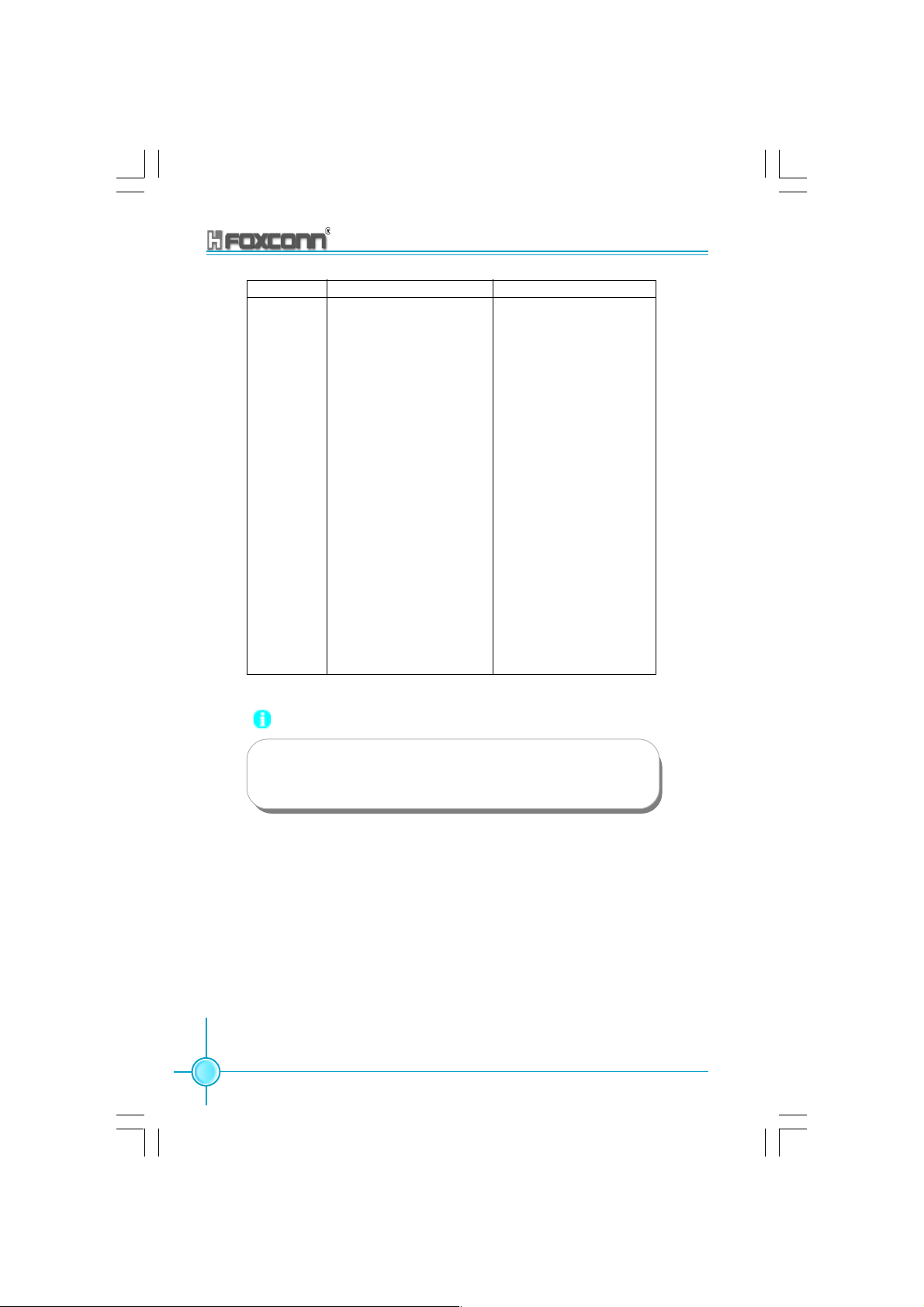
CPU Qualified Vendor List
The following table lists the CPU modules that have been tested and quali-
fied for use with this motherboard.
Vendor Type FSB Frequency
Intel Pentium(Willamete) 400 1.8G
Intel Celeron(Northwood) 400 2.2G,2.6G
Intel Pentium(Northwood) 533 2.4G,2.53G,2.8G
Intel Pentium(Northwood) (HT) 533 3.06G
Intel Pentium(Prescott) 533 2.13G
Intel Pentium(Northwood) 800 2.4G
Intel Pentium(Northwood) (HT) 800 3.2G, 3.4G
Intel Pentium(Prescott) 800 2.80G, 3.0G, 3.2G
Intel Pentium(P4EE) 800 3.0G
Note:
1.Make sure to use only the tested and qualified CPUs listed
above. Other CPUs manufactured by other vendors may
not be suitable for this motherboard.
2.When use the Willamette CPU, please refer to the “CPU
Model Selection Jumper: CN1” of page 39.
875A02 User Manual
15
Page 24

Chapter 2 Installation Instructions
Memory
This motherboard includes four 184-pin slots with 2.6V Double Data Rate (DDR)
Dual Inline Memory Module (DIMM) sockets, so you can install PC3200/2700/
2100 memory. You must install at least one memory bank to ensure normal
operation.
DIMM1
DIMM2
DIMM3
DIMM4
DDR Memory
The DDR SDRAM technology evolved from the mainstream PC66, PC100, PC133
memory known as Single Data Rate (SDR) SDRAM. DDR memory, however,
has the ability to perform two data operations in one clock cycle, thus providing
twice the throughput of SDR memory.
A DDR DIMM has the same physical dimensions as an SDR DIMM, but it has a
184-pin footprint compared to the 168-pin of the SDR DIMM. Also, a DDR DIMM
is single notched while an SDR DIMM is double notched.
Therefore, a DDR DIMM is not backward compatible with SDR, and should be
installed only in a socket specially designed for DDR DIMMs.
16
875A02 User Manual
Page 25

Chapter 2 Installation Instructions
Memory configurations
You may install 128MB, 256MB, 512MB, and 1GB DDR DIMMs into the DIMM
sockets using the memory configurations in this section.
The following is important information on memory configurations:
1. Installing DDR DIMMs other than the recommended configurations may
cause memory sizing errors or system boot failures. Use any of the
recommended configurations in the following table.
Sockets
Mode
Single-channel
Dual-channel
DIMM1 DIMM2 DIMM3 DIMM4
Populated
Populated
xxx
x
x
Populated
xx
xx
Populated
x
x
x
Populated
Populated
xx
xxx
Populated
x
Populated
Populated Populated
x
PopulatedPopulated
x
PopulatedPopulatedPopulated Populated
x
Populated
xx
Populatedx
PopulatedPopulated
Note:
1. Use only identical DDR DIMM pairs
2. For dual-channel configuration, you may install identical
DIMMS in all four sockets or install identical DIMM pairs
in DIMM1 and DIMM3 (yellow sockets), and identical DIMM
pairs in DIMM2 and DIMM4 (blue sockets).
2. In dual-channel configurations, install only identical (the same type and
size) DDR DIMMs for each channel.
3. Always install DIMMs with the same CAS latency. For optimum compatibility,
it is recommended that you obtain memory modules from the same
vendor. See the following list of qualified vendors. The following table
lists the PC3200/2700/2100 memory modules that have been tested
and qualified for use with this motherboard.
875A02 User Manual
17
Page 26
Chapter 2 Installation Instructions
Vender Type Size
Transcend PC2700 (DDR 333) 512M
Transcend PC3200 (DDR 400) 256M, 512M
RAMBO PC2700 (DDR 333) 256M, 512M
RAMBO PC3200 (DDR 400) 256M
Geil PC3200 (DDR 400) 256M
TwinMos PC3200 (DDR 400) 256M
Samsung PC2700 (DDR 333) 1G
Samsung PC3200 (DDR 400) 1G
VDATA PC3200 (DDR 400) 256M
HLX PC3200 (DDR 400) 256M
Apacer PC2700 (DDR 333) 512M
Apacer PC3200 (DDR 400) 256M
Hynix PC2100 (DDR 266) 256M,512M
Hynix PC2700 (DDR 333) 256M
Hynix PC3200 (DDR 400) 256M
18
Note:
Make sure to use only the tested and qualified DDR DIMMS
listed above. Other DDR DIMMs manufactured by other vendors
may not be suitable for this motherboard.
875A02 User Manual
Page 27
Chapter 2 Installation Instructions
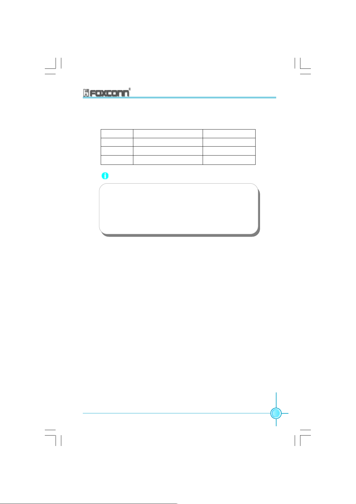
4. Make sure that the memory frequency matches the CPU FSB (Front Side
Bus). Refer to the following table.
CPU FSB DDR DIMM Type Memory Frequency
800 MHz PC3200/PC2700/PC2100 400/333/266 MHz
533 MHz PC2700/PC2100 333/266 MHz
400 MHz PC2100 266 MHz
Note:
1. When using 800MHz CPU FSB,PC2700DDR DIMMs may run
only at 320MHz(not 333MHz) due to chipset limitation.
2.The following FSB/DDR ratios are not supported:400/333,
400/400,533/400.
3. FSB/DDR setting 800/333 is recognized as FSB/DDR 800/
320.
5. DIMMs installed into any three sockets will function in single Channel mode.
6. When all four sockets are populated with 1GB DIMMs (total 4GB), the system
may detect over 3GB (a little less than 4GB) to ICH5R resource allocation.
7. lt is recommended to use the yellow DIMM slots first.
875A02 User Manual
19
Page 28

Chapter 2 Installation Instructions
Installation of DDR Memory
1. There is only one gap in the center of the DIMM slot, and the memory module
can be fixed in one direction only.
2. Align the memory module to the DIMM slot, and insert the module vertically
into the DIMM slot.
104 Pins 80 Pins
3. The plastic clips at both sides of the DIMM slot will lock automatically.
20
Note:
Be sure to unplug the AC power supply before adding or re-
moving expansion cards or other system peripherals, espe-
cially the memory devices, otherwise your motherboard or the
system memory might be seriously damaged.
875A02 User Manual
Page 29

Chapter 2 Installation Instructions
Power Supply
This motherboard uses an ATX power supply. In order to avoid damaging any
devices, make sure that they have been installed properly prior to connecting
the power supply.
ATX 12V Power Connector: PWR2
The 4 pin ATX 12V power supply connects to PWR2 and provides power to the
CPU.
ATX Power Connector: PWR1
PWR1 is the ATX power supply connector. Make sure that the power supply
cable and pins are properly aligned with the connector on the motherboard.
Firmly plug the power supply cable into the connector and make sure it is secure.
ATX 12V Power Connector
24
GND
GND
1
12V
12V
3
ATX 20-pin Power Connector
GND 3.3V GND
5V
1
11
PS-ON -12V
3.3V
GND
GND
5V
GND
GND
Pw-OK 3.3V
GND
5V_SB
NC
5V
Attention:
You have to press the power button for more than four seconds if you
change the default Instant-off setting to “Delay 4 Sec” for the soft-off
by Power Button option in the BIOS Power Management Setup.
875A02 User Manual
12V
10
20
5V
21
Page 30
Chapter 2 Installation Instructions
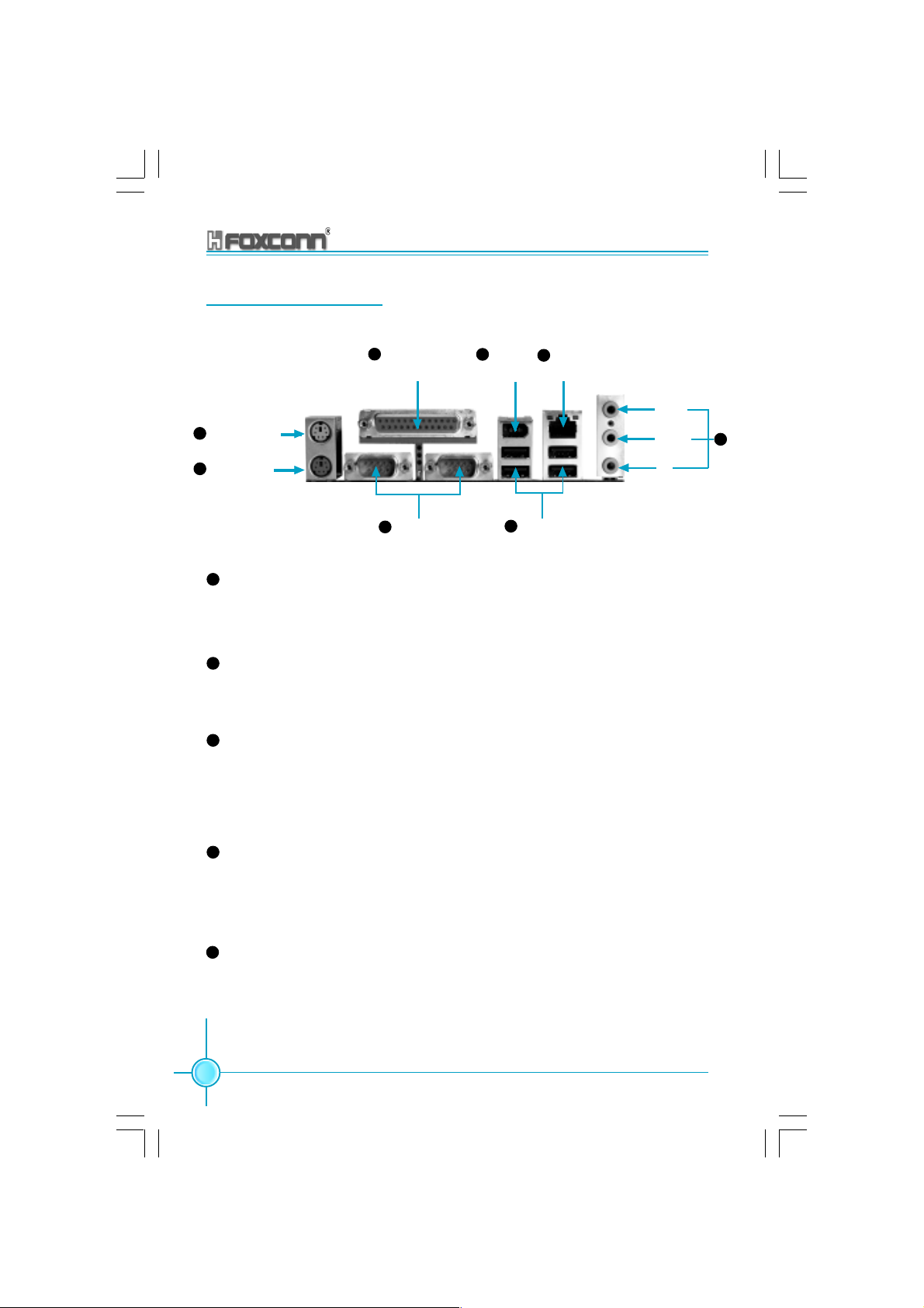
Rear panel Connectors
This motherboard provides the following ports, as below:
1
PS/2 Mouse Port
2
PS/2 Keyboard
Port
1
PS/2 Mouse Port
SPP/EPP/ECP
4
Parallel Interface
(Printer Port)
3
COM 1/2 Ports USB 2.0 Port
1394 Port
6 7
(Optional)
5
LAN Port
(Optional)
Line-in
Line-out
MIC
This motherboard includes one standard PS/2 mouse port. You can connect the PS/2 mouse directly into this port.
2
PS/2 Keyboard Port
This motherboard includes one standard PS/2 keyboard port. If you use a
standard AT keyboard, then you will need a converter to use this port.
3
Serial ports: COM1/COM2
This motherboard includes two 9-pin common adapters for serial ports
COM1/COM2. The ports are the 16550 high-speed communication interface used to transfer and receive 16-byte FIFO. You can connect the sequential mouse or other sequential devices directly to the ports.
8
4
Parallel Port (Printer Port)
This motherboard includes one 25-pin mother connector for LPT. The parallel port is a standard printer port which supports the enhanced parallel
port (EPP), ECP mode, etc.
5
USB 2.0 Ports
These four Universal Serial Bus (USB) ports are available for connecting
USB 2.0 devices.
22
875A02 User Manual
Page 31

Chapter 2 Installation Instructions
6
1394 port (optional)
This digital interface supports electronic devices such as digital cameras,
scanners, and printers.
7
RJ45 10M/100M/1G LAN Port (optional)
If you have purchased the built-in LAN function, the port will be located on
the rear panel.
8
Audio Port
When using a two-channel sound source, the Line-out jack is used to connect to speakers or headphones; the Line-in port connects to an external
CD player, tape player or other audio device. The MIC is used to connect to
the microphone.
Line In
Line Out
Microphone
When using a 6-channel sound source, connect the front speaker to the
green audio output; connect the surround sound speaker to the blue audio
input; connect the central speaker/sub woofer to the red MIC input, as being
shown in the following figure:
Blue
Green
Center
Red
Rear Left
Front Left
Front Right
Rear Right
Subwoofer
875A02 User Manual
23
Page 32

Chapter 2 Installation Instructions
Other Connectors
This motherboard includes interfaces for FDD, IDE, SATA, USB, 1394, IR
module, CPU/system fan, and others.
FDD
This motherboard includes a standard FDD interface, supporting 360K, 720K,
1.2M, 1.44M, and 2.88M FDDs.
FDD Interface
HDD connectors: PIDE & SIDE
These connectors support the provided UltraDMA 100/66/33 IDE hard disk
ribbon cable. Connect the cable’s blue connector to the primary
(recommended) or secondary IDE connector, then connect the gray connector to the Ultra DMA 100/66/33 slave device (hard disk drive) and the black
connector to the Ultra DMA 100/66/33 master device. If you install two hard
disks, you must configure the second drive as a slave device by setting its
jumper accordingly. Refer to the hard disk documentation for the jumper
settings.
24
Attention:
Ribbon cables are directional, therefore, make sure to always
connect with the cable on the same side as pin 1 of the PIDE/
SIDE or FDD connector on the motherboard.
875A02 User Manual
Page 33

Chapter 2 Installation Instructions
SIDE (Secondary IDE Interface)
PIDE(Primary IDE
Interface)
Front Panel Connector: FP1
This motherboard includes one connector for connecting the front panel
switch and LED indicator.
1 2
+ -
9 10
+ -
PLED
PBTN
GND
Key
HD_LED
GND
RST
NC
HD_LED Connector
Attach the connector to the HD_LED on the front panel of the case; the LED
will flash while the HDD is in operation.
Reset Switch
Attach the connector to the Reset switch on the front panel of the case; the
system will restart when the switch is pressed.
Power LED Connector
Attach the connector to the power LED on the front panel of the case. The
Power LED indicates the power supply status, and will be lit during normal
system operation. The Power LED will blink while the system is in the S1
mode, and will be turned off when the system is in either S3 or S5 mode.
875A02 User Manual
25
Page 34

Chapter 2 Installation Instructions
IrDA Header: IR
The IrDA infrared transmission allows your computer to send and receive
data via an infrared ray. The relevant parameters for the BIOS Integrated
Peripherals should be set prior to using this function.
1
IR
5V-SYS
Key
IRRX
GND
IRTX
26
875A02 User Manual
Page 35

Chapter 2 Installation Instructions
USB Header: F_USB1, F_USB2
If the USB ports on the rear panel are inadequate, a USB header is available for
additional USB ports. The USB header complies with USB 2.0 specification that
supports up to 480 Mbps connection speed. This speed advantage over the
conventional 12 Mb on USB 1.1 allows faster Internet connection, interactive
gaming, and simultaneous running of high-speed peripherals.
1 2
VCC
D5-
D5+
GND
KEY
F_USB1
1 2
VCC
D7-
D7+
GND
KEY
F_USB2
VCC
D6-
D6+
GND
NC
9 10
VCC
D8-
D8+
GND
NC
9 10
Note:
1. You must install the driver before you can use the USB 2.0
function.
2. NEVER connect a 1394 cable to the F_USB1 or F_USB2
connectors. Doing so will damage the motherboard!
3. The USB cable is an optional item.
875A02 User Manual
27
Page 36

Chapter 2 Installation Instructions
Fan Connectors: CPU_FAN, GMCH_FAN, FAN1
There are three fan headers on this motherboard. The fans are always turned
ON in S0/S1 modes and OFF in S3/S4/S5 modes. The CPU/system fan speed
can be monitored in the PC Health section of the BIOS.
1
GND
NC
+12V
GND
1
CPU_FAN
GMCH_FAN
FAN1
+12V
SENSE
1
+12V
SENSE
GND
Audio Connectors: CD_IN, AUX_IN
To receive audio input from the CD-ROM, attach its audio connector to the CD_IN/
AUX_IN audio headers on the motherboard.
28
1
1
875A02 User Manual
CD_R
GND
CD_L
AUX_L
GND
AUX_R
CD_IN
AUX_IN
Page 37

Chapter 2 Installation Instructions
1394 Header: F_1394 (Optional)
The 1394 expansion cable can be connected to either the front (provided that
the front panel of your chassis is equipped with the appropriate interface) or
real panel of the chassis.
10 9
GND
PWR
TPB-
GND
TPA-
2 1
F_1394
Wake-up On LAN: WOL
Through the Wake-Up On LAN function, a wake event occurring from the
network can wake up the system. To utilize this function, please be sure to
use an ATX 12V power supply with a 5VSB line capable of delivering a current
of at least 720mA, and a LAN adapter which supports this function. Then
connect the header to the relevant connector on the LAN adapter, set “Wake
up by PCI Card” to enabled in the “POWER MANAGEMENT SETUP” section
of the CMOS SETUP. Save and exit, then boot the operating system once to
make sure this function takes effect.
Key
PWR
TPB+
GND
TPA+
875A02 User Manual
1
WOL
Signal for waking up
GND
+5VSB
29
Page 38

Chapter 2 Installation Instructions
S-ATA Connectors: SATA1, SATA2, SATA3, SATA4
The S-ATA header is used to connect the S-ATA device to the motherboard.
These connectors support the thin Serial ATA cables for primary internal
storage devices. The current Serial ATA interface allows up to 150MB/s data
transfer rate, faster than the standard parallel ATA with 133MB/s (Ultra ATA/
133).
GND
RX+
RX-
GND
TX-
TX+
GND
SATA4/SATA3
GND
TX+
TX-
GND
RX-
RX+
GND
SATA1/SATA2
Serial ATA solution:
1. In legacy operating system (Win98, WinME, WinNT, DOS) enviromemt,
using Serial ATA will disable one of the IDE channels. See the BIOS
section for correct settings.
2. The Serial ATA cable is smaller and more flexible allowing easier routing
inside the chassis. The lower pin count of the Serial ATA cable eliminates
the problem caused by the wide, flat ribbon cables of the Parallel ATA
interface.
3. The IAA-RAID driver is available for WinXP/2000 only.
4. RAID 0 and RAID 1 are supported.
5. Install WinXP Service Pack1 when using Serial ATA.
30
875A02 User Manual
Page 39

Chapter 2 Installation Instructions
Parallel ATA and Serial ATA device configurations:
Following are the Parallel ATA and Serial ATA device configurations supported
by Intel ICH5R specifications.
P-ATA S-ATA
Operating System Primary Secondary Port 0 Port1
(2 devices) (2 devices) (1 device) (1 device)
1.Windows 2000/XP
2.Windows 98/ME/NT4.0
Configuration 1
Configuration 2
Configuration 3
NOTE:
Supported
Disabled
875A02 User Manual
31
Page 40

Chapter 2 Installation Instructions
Audio Header: F_AUDIO
The audio port includes two parts – the Front Audio and Rear Audio. Their priority
is sequenced from high to low (Front Audio to Rear Audio). If headphones are
plugged into the front panel of the chassis (using the Front Audio), then the
Speaker Out (Rear Audio) on the rear panel will not work. If you do not want to
use the Front Audio, pin 5 , 6, 9 and 10 must be short connected, and then the
signal will be sent to the rear audio port.
1
F_MIC GNDA
5VA
FOUT_R
NC
FOUT_L OUT_L
2
5VA
OUT_R
KEY
910
F_Audio
S/PDIF Out Connector: SPDIF
The SPDIF_OUT output is capable of providing digital or 6 channel audio to
external speakers, or compressed AC3 data to an external Dolby digital decoder.
The motherboard is equipped with one bracket.
GND
SPDIF_OUT
KEY
5V
1
SPDIF_OUT
32
875A02 User Manual
Page 41

Chapter 2 Installation Instructions
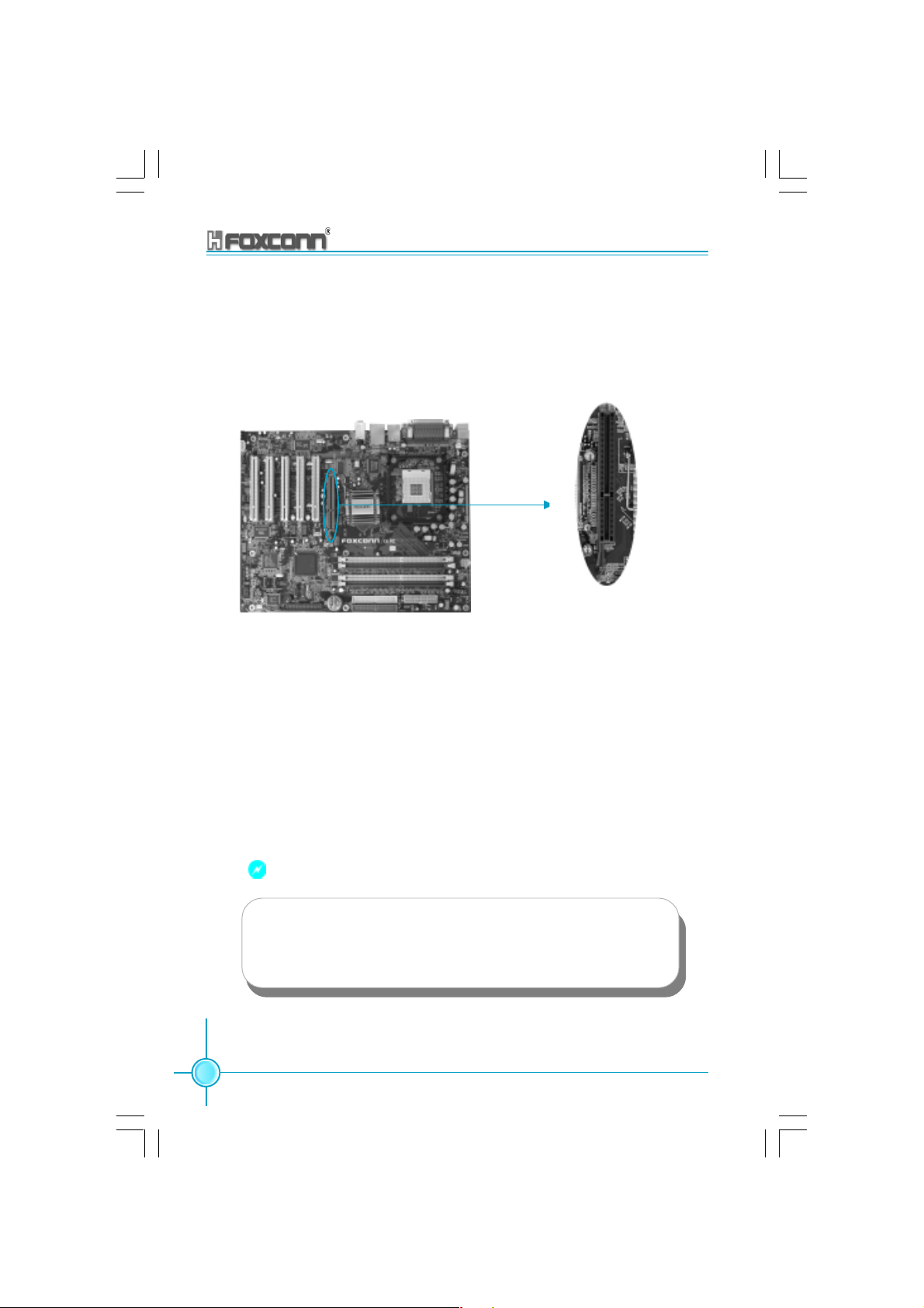
Expansion Slots
This motherboard includes five 32-bit Master PCI bus slots and one AGP
slot.
PCI Slots
The expansion cards can be installed in the five PCI slots. When you install
or take out such cards, you must make sure that the power plug has been
pulled out. Please read carefully the instructions provided for such cards,
and install and set the necessary hardware and software for such cards,
such as the jumper or BIOS settings.
PCI Slot
875A02 User Manual
33
Page 42
Chapter 2 Installation Instructions
AGP Slot (Accelerated Graphic Port)
This motherboard has Accelerated Graphics Port (AGP) slot that only Supports
+1.5V AGP cards. When you use an AGP card, make sure that your AGP card with
+1.5V specification. Note the notches on the card Golden fingers to ensure that
they fit the AGP slot on your motherboard.
AGP Slot
Installing an expansion card
1. Before installing the expansion card, read the documentation that came with
it and make the necessary hardware settings for the card.
2. Make sure to unplug the power cord before adding or removing expansion
cards.
3. Remove the bracket opposite the slot that you intend to use.
4. Align the card connector with the slot and press firmly until the card is
completely seated on the slot.
5. Secure the card to the chassis with the screw you removed earlier.
34
Warning:
The motherboard may be damaged if a 3.3V AGP card is used.
Make sure that your AGP card is 1.5V specification. Note the
notches on the card golden fingers to ensure that they fit the AGP
slot on your motherboard.
875A02 User Manual
Page 43

Chapter 2 Installation Instructions
AGP Qualified Vendor List
The following table lists the AGP modules that have been tested and qualified
for use with this Motherboard.
Vender Type Video Memory
GIGABYTE GA-GF1280 Geforce 2 MX 32MB DDR
UNIKA UNIKA 7917 Geforce 4 MX440 64MB DDR
ELSA ELSA 920 64MB DDR
MSI MSI Ti 4200 8X 128MB DDR
ATI ATI 9700 pro 8X 128MB DDR
ATI ATI 9800 pro 8X 128MB DDR
ATI ATI 9500 8X 128MB DDR
ATI ATI 7000 128MB DDR
YING TONG Ying Tong A96 ATI 9600 8X 128MB DDR
QDI QDI FX5200 128MB DDR
ASUS ASUS V9280/TD 8X 128MB DDR
Note:
Make sure to use only the tested and qualified AGP cards listed
above. Other AGP cards manufactured by other vendors may
not be suitable for this motherboard.
875A02 User Manual
35
Page 44

Chapter 2 Installation Instructions
Jumpers
Users can change the jumper settings on this motherboard if needed. This
section explains how to use the various functions of this motherboard by changing the jumper settings. Users should read the following contents carefully prior
to modifying any jumper settings.
Description of Jumpers
1. For the jumpers on this motherboard, pin 1 can be identified by the silkscreen
printed “ ” next to it. However, in this manual, pin 1 is simply labeled as “1”.
2. The following table provides some explanation of the jumper pin settings.
Users should refer to this when adjusting jumper settings.
Jumper Diagram Definition Description
1
1
1
1
1
1
1-2 Set pin 1 and pin 2 closed
2-3 Set pin 2 and pin 3 closed
Closed Set the pin closed
Open Set the pin opened
36
875A02 User Manual
Page 45

Chapter 2 Installation Instructions
Clear CMOS Jumper: CLS_CMOS
This motherboard uses the CMOS RAM to store all the set parameters. The
CMOS can be cleared by removing the CMOS jumper. How to clear CMOS?
1. Turn off the AC power supply and connect pins 1 and 2 together using the
jumper cap.
2. Return the jumper setting to normal (pins 2 and 3 locked together with the
jumper cap).
3. Turn the AC power supply back on.
Normal status
(default)
Clear CMOS
(Unplug the AC power supply)
1
2
3
1
2
3
CLS_CMOS
Warning:
1. Disconnect the power cable before adjusting the jumper
settings.
2. Do not clear the CMOS while the system is turned on.
875A02 User Manual
37
Page 46

Chapter 2 Installation Instructions
Anti-virus BIOS Write Protect Jumper: FWH_EN
To protect the system BIOS from viruses, this motherboard is designed with
a BIOS write-protection jumper (FWH_EN). Close pins 1 and 2 on FWH_EN
and disable SuperBIOS-Protect in the BIOS, and then the BIOS can be
flashed. (Note: the default setting for pins 2 and 3 on FWH_EN is “closed”.)
Flash Write
disable
Flash Write
enable
(default)
1
2
3
FWH_EN
1
2
3
FWH_EN
LAN Disabled Jumper: LAN_DIS
Close pins 1 and 2 on LAN_DIS and enable the onboard lan. If LAN_DIS is set
pins 2 and 3 at closed, then the onboard lan is disabled.
Onboard
LAN
Enable
Onboard
LAN
Disable
1
2
3
LAN_DIS
1
2
3
LAN_DIS
38
875A02 User Manual
Page 47

Chapter 2 Installation Instructions
CPU Model Selection Jumper: CN1
The default status for CN1 is Open, which supports the Prescott and Northwood
CPU. If CN1 is set at Closed, then it supports the Willamette CPU.
1
Closed
2
CN1
Open
(Default)
1
2
CN1
875A02 User Manual
39
Page 48

Chapter 2 Installation Instructions
Starting up for the first time
1. After making all the connections, replace the system case cover.
2. Be sure that all switches are off.
3. Turn on the devices in the following order.
a. Monitor
b. External SCSI devices (starting with the last device on the chain)
c. System power
4. After applying power Led on the system front panel case lights up. For ATX
power supplies, the system LED lights up when you press the ATX power
switch. If your monitor complies with green standards or if it has a power
standby feature, the monitor LED may light up or switch between orange
and green after the system LED turns on. The system then runs the Power
On Self Tests. While the tests are running, the BIOS beeps or additional
messages appear on the screen. If you do not see anything within 30
seconds from the time you turned on the power, the system may have failed
a power-on test. Check the jumper settings and connections or call your
retailer for assistance.
5. At power on, hold down <Delete> to enter BIOS Setup. Follow the
instructions in Chapter 3.
Powering off the computer
1. Using the OS shut down function
If you use windows 98SE/ME/2000/XP, click the Start button, click Shut
Down, then the OK button to shut down the computer. The power supply
should turn off after Windows shuts down.
2.Using the dual function power switch
While the system is ON, pressing the power switch for less than 4
seconds puts the system to sleep mode or to soft-off mode, depending
on the BIOS setting. Pressing the power switch for more than 4 seconds
lets the system enter the soft-off mode regardless of the BIOS setting.
40
875A02 User Manual
Page 49

Chapter
This chapter introduces the 875A02 motherboard’s CMOS
Setup program, which allows users to configure optimized
system settings.
You have to run the Setup Program when the following
cases occur:
1. An error message appears on the screen during the
2. You want to change the default CMOS settings.
3
3
system POST process.
This chapter includes the following information:
Enter BIOS Setup
Main Menu
Standard CMOS Features
BIOS Features
Advanced BIOS Features
Advanced Chipset Features
Integrated Peripherals
Power Management Setup
PnP/PCI Configurations
PC Health Status
Frequency/Voltage Control
Load Fail-Safe Defaults
Load Optimized Defaults
Set Supervisor/User Password
Save & Exit Setup
Exit without Saving
Page 50

Chapter 3 BIOS Description
Enter BIOS Setup
After the computer is powered on, the BIOS will self -diagnose the basic
hardware on the motherboard (POST process), set up the time sequence
parameters for hardware, detect the hardware devices, etc.. After the POST
process is completed, control of the system will be transferred to the operating system. Since the BIOS is the communication bridge between hardware
and software, correctly setting up the BIOS parameters is critical to maintain
optimal system performance. In general, when the computer is turned on
and while BIOS is executing the POST process, the following message will
appear in the lower left corner of the screen:
Press TAB to show POST Screen, DEL to enter SETUP.
If you want to enter the BIOS, you must press the <Del> button within 3-5
seconds of the appearance of the above message.
Remark:
If you want to enter the BIOS, you must press the <Del> button
within 3-5 seconds of the appearance of the above message.
Main Menu
The main menu allows you to select from the list of setup functions and two
exit choices. Use the arrow keys to select among the items and press
<Enter> to accept or go to the sub-menu.
Main Menu
The items in the BIOS Setup main menu are explained below:
Standard CMOS Features
The basic system configuration can be set up through this menu.
BIOS Features
The general system features can be set up through this menu.
42
875A02 User Manual
Page 51

Chapter 3 BIOS Description
Advanced BIOS Features
The advanced system features can be set up through this menu.
Advanced Chipset Features
The register values for the chipset can be changed through this menu, and
the system performance can be optimized.
Integrated Peripherals
Special settings for peripheral devices can be modified through this menu.
Power Management Setup
The system’s power management setting can be modified through this menu.
PnP/PCI Configurations
The system’s PnP/PCI settings and parameters can be modified through
this menu.
PC Health Status
This will display the current status of your PC.
Frequency/Voltage Control
Frequency and voltage setting can be adjusted through this menu.
Load Fail-Safe Defaults
The default BIOS settings can be loaded through this menu.
Load Optimized Defaults
The optimal performance settings can be loaded through this menu,
however, the stable default values may be affected.
Set Supervisor Password
The supervisor password can be set up through this menu.
Set User Password
The user password can be set up through this menu.
Save & Exit Setup
Save the change(s) made to the CMOS settings and exit Setup.
Exit Without Saving
Abandon the change(s) made to the CMOS settings and exit Setup.
875A02 User Manual
43
Page 52

Chapter 3 BIOS Description
Standard CMOS Features
This sub-menu is used to set up the standard CMOS features, such as the
date, time, HDD model and so on. Use the arrow keys select the item to set
up, and then use the <PgUp> or <PgDn> keys to choose the setting values.
Date
This option allows you to set the desired date (usually as the current day)
with the <day><month><date><year> format.
day weekday from Sun. to Sat., defined by BIOS (read-only).
month month from Jan. to Dec.
date date from 1st to 31st, can be changed by using the keyboard.
year year,set up by users.
Time
This option allows you to set up the desired time (usually the current
day) with <hour><minute><second> format.
IDE Channel 0/1 Master/Slave (First channel master/slave HDD/sec-
ond master/slave HDD)
You can select this option by pressing the <Enter> key, and the BIOS will
detect the current HDD model. The HDD type can be selected using <PgUP>/
<+> or <PgDn>/<-> . “None” means that no HDD is currently installed; “Auto”
means that the BIOS will automatically detect and set the HDD type after the
system is started up with HDD; when “Manual” is selected and the Access
Mode is changed to CHS, the system will request you to key in the following
HDD parameters:
Cylinder number of cylinders Head number of heads
Precomp write pre-compensation Landing Zone Landing Zone
Sector number of sectors
44
875A02 User Manual
Page 53

Chapter 3 BIOS Description
Award (Phoenix) BIOS can support 3 HDD modes: CHS, LBA and Large or
Auto mode.
CHS For HDD<528MB
LBA For HDD>828MB & supporting LBA (Logical Block Addressing)
Large For HDD>528MB but not supporting LBA
Auto Recommended mode
Drive A/B (FDD A/B)
This option allows you to select the kind of FDD to be installed, including
“None”, [360K, 5.25in], [1.2M, 5.25in], [720K, 3.5in], [1.44M, 3.5in] and [2.88
M, 3.5in].
Video (Display Card)
The following table is provided for your reference in setting the display mode for
your system.
EGA/ VGA Enhanced Graphics Adapter / Video Graphic Array. For EGA,
VGA, SEGA, SVGA, or PGA monitor adapters.
CGA 40 Color Graphic Adapter, powering up in 40 column mode.
CGA 80 Color Graphic Adapter, powering up in 80 column mode.
MONO Monochrome adapter, including high resolution monochrome
adapters.
Halt On
This option can be used to set your PC to stop if any error(s) occur after the
system has started.
All errors The system will stop and display the prompt when-
ever an error is detected.
No errors The system will start as usual even if an error is
detected
All, But Keyboard The system will stop when any error other than
keyboard error occurs
All, But Diskette The system will stop when any error other than disk
error occurs
All, But Disk/Key The system will stop when any error other than
keyboard or disk error occurs
875A02 User Manual
45
Page 54

Chapter 3 BIOS Description
Memory
This displays the system storage information detected by BIOS during the
Power on self test (POST).
Base Memory The basic memory capacity loaded in the system
is determined by BIOS during the POST.
Extended Memory The extended memory capacity is determined by
BIOS during the POST.
Total Memory The total of all memory capacities.
46
875A02 User Manual
Page 55

Chapter 3 BIOS Description
BIOS Features
BIOS Features Menu
[SuperBoot] SuperBoot (Default: Disabled)
SuperBoot allows system-relevant information to be stored in CMOS upon
the first normal startup of your PC, and the relevant parameters will be
restored to help the system start up more quickly on each subsequent startup.
The available setting values are: Disabled and Enabled.
Note: Disabled and Enabled have the same meaning if in the following
sections of this Manual.
[SuperBIOS-Protect] Super-BIOS Protect (Default: Disabled)
Super-BIOS Protect Funtion protects PC from viruses,e.g. CIH, by using a
HW/SW double BIOS lock technology. The available setting values are:
Disabled and Enabled.
[SuperRecovery] SuperRecovery Hotkey (Default: LSHIFT+F12)
SuperRecovery provides the users with an excellent data protection and
HDD recovery function. There are 12 optional settings, and the default
setting is LSHIFT+F12.
[SuperSpeed] CPU Clock (Depending on the specification of the
CPU)
The conventional over-clock method uses the jumpers on the motherboard,
and it is both troublesome and apt to errors. By using SuperSpeed, a
CPU can be overclocked by keying in the desired. If you use FSB 400 MHz
CPU, the setting range is from 100 MHz to 132 MHz; FSB 533 MHz CPU,
the setting range is from 133 MHz to 165 MHz; FSB 800 MHz CPU, the
setting range is from 200 MHz to 232 MHz.
Warning:
Be sure your selection is right. CPU over speed will be dangerous!
We will not be responsible for any damages caused.
875A02 User Manual
47
Page 56

Chapter 3 BIOS Description
Advanced BIOS Features
Advanced BIOS Features Menu
CPU Feature
Press <Enter> to set the items of CPU feature. Please refer to page 51.
Hard Disk Boot Priority
This option is used to select the priority for HDD startup. After pressing
<Enter>, you can select the HDD using the <PageUp>/<PageDn> or Up/
Down arrow keys, and change the HDD priority using <+> or <->; you can
exit this menu by pressing <Esc>.
CPU L1 & L2 Cache (Default: Enabled)
This option is used to turn on or off the CPU L1 and L2 cache. The available
setting values are: Disabled and Enabled.
CPU L3 Cache (Default: Enabled)
This option is used to turn on or off the L3 CPU cache. The available
setting values are: Disabled and Enabled.
Note: This function will not be displayed until a CPU with CPU L3 cache has
been installed.
Hyper-Threading Technology (Default: Enabled)
This option is used to turn on or off the Hyper-threading function of the
CPU. The available setting values are: Disabled and Enabled.
Note: This function will not be displayed until a CPU that supports HyperThreading has been installed.
Quick Power On Self Test (Default: Enabled)
With this function enabled, the system will skip the normal test while
starting up, therefore reducing the overall start up time. The available
setting values are: Disabled and Enabled.
48
875A02 User Manual
Page 57

Chapter 3 BIOS Description
First/Second/Third Boot Device (Default: Floppy/Hard Disk/LS120)
This option allows you to set the boot device sequence. The available setting
values are: Floppy, LS120, Hard Disk, CDROM, ZIP100, USB-FDD, USB-ZIP,
USB-CDROM, LAN, and Disabled.
Boot Other Device (Default: Enabled)
With this function set to Enabled, the system will boot from some other device
if the first/second/third starting devices failed.
Swap Floppy Drive (Default: Disabled)
If it is set to Enabled, the label of FDD A and B can be exchanged. The
available setting values are: Disabled and Enabled.
Boot Up Floppy Seek (Default: Enabled)
If it is set to Enabled, BIOS will activate the floppy drive during the system boot,
and the drive’s indicator will flash after the activation.The magnetic head will
move back and forth from A to B. The available setting values are: Disabled
and Enabled.
Boot Up NumLock Status (Default: On)
This option is used to set up the NumLock status after the startup. When it is
set to On, the NumLock will be activated during system startup. When it is set
to Off, users can use the number keys instead of the arrow keys to move the
cursor. The available setting values are: On and Off.
Gate A20 Option (Default: Fast)
This option is used to set up the A20 signal control necessary for access to
the 1MB memory. The available setting values are: Normal and Fast.
Typematic Rate Setting (Default: Disabled)
When it is set to Enabled, the 2 subsequent options can be activated; when it
is set to Disabled, the 2 subsequent options will be closed.
Typematic Rate (Chars/Sec) (Default: 6)
Used to set the repeat rate for keyboard input of the same letter.
Typematic Delay (Msec) (Default: 250)
Used to set the repeat keyboard input rate when pressing a key continuously.
875A02 User Manual
49
Page 58

Chapter 3 BIOS Description
Security Option (Default: Setup)
When it is set to Setup, a password is required to enter the CMOS Setup
screen; When it is set to System, a password is required not only to enter
CMOS Setup, but also to startup your PC, as well.
APIC Mode (Default: Enabled)
This option is used to open or lock the APIC mode built into the chipset.
The available setting values are: Disabled and Enabled.
MPS Version Control For OS (Default: 1.4)
This option is used to set up the version of MPS Table used in NT4.0 OS.
OS Select For DRAM > 64MB (Default: Non-OS2)
With it set to Non-OS/2, you cannot execute the OS/2 in the system with the
memory > 64MB; with OS/2 selected, you are allowed to execute the OS/2
in the system with the memory > 64MB.
Report No FDD For WIN 95 (Default: No)
FDD Set whether BIOS reports Windows 95 or not loading floppy disk
drive. The available setting values are: No and Yes.
Small Logo (EPA) Show (Default: Disabled)
Determines whether the small logo (EPA) will be displayed during system
startup. The available setting values are: Disabled and Enabled.
50
875A02 User Manual
Page 59

Chapter 3 BIOS Description
CPU Feature Menu
Delay Prior to Thermal (Default: 16 Min)
This option is used to set up the time for CPU to enter the energy-saving
mode.
Thermal Management (Default: Thermal Monitor 1)
This option is used to manage Prescott CPU thermal.
Note: This function will not be displayed until a Prescott CPU has been installed.
875A02 User Manual
51
Page 60
Chapter 3 BIOS Description
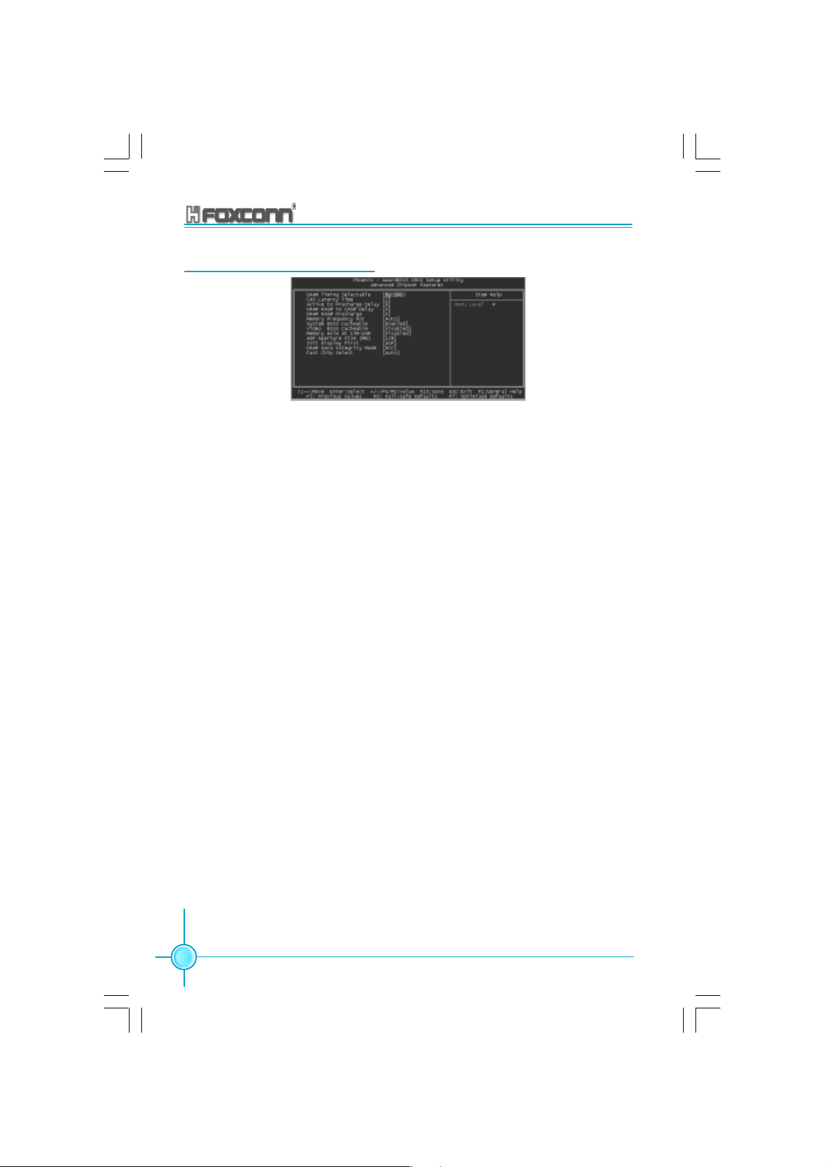
Advanced Chipset Features
Advanced Chipset Features Menu
DRAM Timing Selectable (Default: By SPD)
This option is used to set the signal time sequence of the DRAM. The “By
SPD” DRAM speed is controlled by the DRAM data register, and the “By
Manual” DRAM speed is controlled by the user.
CAS Latency Time (Default: depend on memory)
This item determines CAS Latency. The available setting values are: 2,
2.5 and 3.
Active to Precharge Delay (Default: depend on memory)
This item allows you to select DRAM Active to Precharge Delay. The
available setting values are: 8, 7, 6 and 5.
DRAM RAS# to CAS# Delay (Default: depend on memory)
This item allows you to select a delay time between the CAS and RAS strobe
signals. The available setting values are: 4, 3, and 2.
DRAM RAS# Precharge (Default: depend on memory)
This item allows you to select the DRAM RAS# precharge time. The
available setting values are: 4, 3, and 2.
Memory Frequency For (Default: Auto)
It sets the frequency for memory.
Note: The operating frequency will be 320MHz when a 800MHz CPU and
a DDR333MHz are used jointly.
System BIOS Cacheable (Default: Enabled)
This option is used to determine whether the system BIOS is written into
the buffer memory. The available setting values are: Disabled and Enabled.
52
875A02 User Manual
Page 61

Chapter 3 BIOS Description
Video BIOS Cacheable (Default: Disabled)
This option is used to determine whether the Video BIOS is written into the
buffer memory. The available setting values are: Disabled and Enabled.
Memory Hole At 15M-16M (Default: Disabled)
This option is used to determine whether the 15M-16M address field of
memory is reserved for the ISA expansion card. The available setting values
are: Disabled and Enabled.
AGP Aperture Size (MB) (Default: 128)
This option is used to set up the memory size occupied by AGP card.
Note: This function does not work when Onboard VGA is used.
Init Display First (Default: AGP)
This option is used to set which display device will be used first when your PC
starts up. The available setting values are: AGP and PCI Slot.
DRAM Data Integrity Mode (Default: ECC)
This option is used to set the DRAM data integrity mode. The available setting
values are: ECC and Non-ECC.
Fast Chip Select (Default: Auto)
This option allows you to set the Intel® PAT function, select “Enabled” for the
®
Intel
PAT function is OK. The available setting values are: Auto and Enabled.
875A02 User Manual
53
Page 62

Chapter 3 BIOS Description
Integrated Peripherals
Integrated Peripherals Menu
Use the arrow keys to select your options; press the <Enter> key to enter the
setup menu. The options and setting methods are discussed below:
Onchip IDE Device Menu
IDE HDD Block Mode (Default: Enabled)
This option is used to set whether the IDE HDD Block Mode is allowed. The
available setting values are: Disabled and Enabled.
IDE DMA transfer access (Default: Enabled)
This option is used to set up the IDE transfer access—with it set to Enabled,
the IDE Transfer Access uses the DMA mode; with it set to Disabled, the IDE
Transfer Access uses the PIO mode.
On-Chip Primary PCI IDE (Default: Enabled)
This option is used to set whether the On-chip Primary PCI IDE interface is
used. The available setting values are: Disabled and Enabled.
IDE Primary Master/Slave PIO (Default: Auto)
This option is used to set the PIO transfer mode under the IDE Primary
Master/Slave Controller. PIO transfer mode options include Auto/0/1/2/3/4.
Set the transfer mode according to the IDE specification. It is recommended
to set it to Auto for the auto-test by BIOS.
54
875A02 User Manual
Page 63

Chapter 3 BIOS Description
IDE Primary Master/Slave UDMA (Default: Auto)
This option is used to set whether the IDE Primary Master/Slave Unit supports
Ultra DMA. With it set to Auto, BIOS will automatically test whether IDE sup
ports Ultra DMA; with it set to Disabled, the Ultra DMA function will be locked.
On-Chip Secondary PCI IDE (Default: Enabled)
This option is used to set whether the On-chip Secondary PCI IDE is used. The
available setting values are: Disabled and Enabled.
IDE Secondary Master/Slave PIO (Default: Auto)
This option is used to set the PIO transfer mode under the IDE Secondary Master/
Slave Controller. With it set to Auto, BIOS will automatically detect whether IDE
supports the Ultra DMA; with it set to Disabled, the Ultra DMA function will be
locked.
IDE Secondary Master/Slave UDMA (Default: Auto)
This option is used to set whether the second group of primary/secondary
equipment supports Ultra DMA. If the setting is Auto, BIOS will automatically
detect whether the IDE hard disk supports Ultra DMA; if the setting is Disabled,
it will be locked
SATA Mode(Default: IDE)
This option is used to set the SATA mode. When it is set to IDE, the mode will
be IDE only. The available setting values are: IDE and RAID.
Note:If want to use Raid Function, On-Chip Serial ATA must be set Enhance
mode.
On-Chip Serial ATA (Default: Auto)
This option is used to set the On-chip Serial ATA function. When it is set to
Disabled, the function will be locked; when it is set to Auto, the BIOS will lock
the function; with it set to Combined Mode, four HDDs at most will be
supported; with it set to Enhanced Mode, six HDDs at most will be supported
(for those under Windows 2000 and WindowsXP only); with it set to S-ATA Only,
only the S-ATA HDD can be used.
Serial ATA Port 0/1 Mode (Default: SATA0/1 master)
This option is used to set the Serial ATA Port 0/1 Mode.With the mode set to
Primary Master/Slave, the Primary IDE cannot be used; only the secondary
IDE and SATA ports 0/1 will be available. With the mode set to Secondary
Master/Slave, the secondary IDE will be unavailable; only the primary IDE and
SATA ports 0/1 can be used. With the mode set to Primary/Secondary Master,
and the option SATA Only selected, the SATA HDD acts as both the primary and
secondary drive. With the mode set to SATA 0/1 Master and the option SATA
Enhanced Mode selected, both IDE ports and both SATA ports will be available.
875A02 User Manual
55
Page 64

Chapter 3 BIOS Description
Onboard Device Menu
USB Controller (Default: Enabled)
This option is used to set whether the USB Controller is enabled. The
available setting values are: Disabled and Enabled.
USB 2.0 Controller (Default: Enabled)
This option is used to set whether the USB 2.0 Controller is enabled. The
available setting values are: Disabled and Enabled.
USB Keyboard Support (Default: Enabled)
This option is used to set whether the USB Keyboard Controller is enabled
under the conventional operating system. The available setting values
are: Disabled and Enabled.
USB Mouse Support (Default: Enabled)
This option is used to set whether the USB Mouse Controller is enabled
under the conventional operating system. The available setting values are:
Disabled and Enabled.
AC97 Audio (Default: Auto)
This item allows you select AC97 Audio chip to support Audio. Disable this
item if you are going to install a PCI audio added on card. The available
setting values are: Disabled and Auto.
Onboard Lan Controller (Default: Enabled)
This option allows you to enable or disable the onboard LAN function. The
available setting values are: Disabled and Enabled.
Onboard Lan Boot ROM (Default: Disabled)
This option allows you to enable or disable the onboard Lan Boot ROM function.
The available setting values are: Disabled and Enabled.
56
875A02 User Manual
Page 65

Chapter 3 BIOS Description
Super IO Device Menu
POWER On Function (Default: BUTTON ONLY)
This option is used to set the power on method for your PC. Setting values
include: Button Only, Password, Hot-key, Mouse Left, Mouse Right, Any Key
and Keyboard 98 (keyboard is consistent with Windows 98 Standard).
KB Power ON Password (Default: Enter)
This option is used to set the PC Startup with Keyboard function. You will
be prompted to enter the password after pressing the <Enter> key.
Note: This function will only work when the Power On function is set to
Password, or you can not change it.
Hot Key Power ON (Default: Ctrl-F1)
This option is used to set which hot keys will be used for the Power On
Function (when it is set to Hot Key for Startup). The available setting values
are: Ctrl+F1-F12.
Onboard FDC Controller (Default: Enabled)
This option is used to set whether the Onboard FDC Controller is enabled.
The available setting values are: Disabled and Enabled.
Onboard Serial Port 1/2 (Default: 3F8/IRQ4/2F8/IRQ3)
This option is used to set the signal requested for address and
interruption for the Onboard Serial Port 1/2. Setting values include 2F8/
IRQ3, 3F8/IRQ4, 3E8/IRQ4, 2E8/IRQ3, Auto and Disabled.
Note: Do not try to set the same values for serial ports 1 and 2.
UART Mode Select (Default: Normal)
Use this option to select the UART mode. Setting values include Normal,
IrDA, and ASKIR. The setting value is determined by the infrared module
installed on the board. When it is set to IrDA and ASKIR, the UART supports
communication with the MB by means of the infrared module; when it is set
to Normal, the infrared function is unavailable.
875A02 User Manual
57
Page 66

Chapter 3 BIOS Description
RxD, TxD Active (Default: Hi, Lo)
This option is used to set the RxD and TxD parameters, for example, Hi/Hi, Hi/Lo,
Lo/Hi and Lo/Lo.
IR Transmission Delay (Default: Enabled)
This option is used to set whether the IR Transmission Delay is enabled. The
available setting values are: Disabled and Enabled.
UR2 Duplex Mode (Default: Half)
When the UART Mode Select option is set as any one than the Normal, you can
select this option. This option is used to set the UART operating mode. Setting
values include Full (full duplex) and Half (half duplex).
Full duplex means that data can be sent and received synchronously, where as
this is not possible in half duplex mode.
Use IR Pins (Default: IR-Rx2Tx2)
It is recommended not to change the default setting.
Onboard Parallel Port (Default: 378/IRQ7)
This option is used to define the address for the Onboard Parallel Port and the
channel for IRQ. Setting values include Disabled, 378/IRQ7, 278/IRQ5 and
3BC/IRQ7.
Parallel Port Mode (Default: SPP)
This option is used to specify the data transmission protocol for the Parallel
Port, with five options: SPP, EPP, ECP, ECP+EPP and Normal.
The Normal mode only supports data output; ECP and EPP modes support the
two-way transmission of data input and output. ECP and EPP modes are applicable
only to devices known of the ECP and EPP.
EPP Mode Select (Default: EPP1.7)
When the Parallel Port Mode is set to either EPP or ECP+EPP, this option can
be used to select V1.7 or V1.9 for the EPP mode.
ECP Mode Use DMA (Default: 3)
When the Parallel Port Mode is set to ECP or ECP+ EPP, this option is used to
select the channel for the ECP mode. Setting values are 1 and 3.
PWRON After PWR-Fail (Default: Off)
This option is used to set what action the PC will take with the power supply
when it resumes after a sudden power failure. The available options are Off
(remain in turnoff status), On (restart) and Former-Sts (resume with the previous
status).
58
875A02 User Manual
Page 67

Chapter 3 BIOS Description
Power Management Setup
Power Management Setup Menu
ACPI Function (Default: Enabled)
ACPI stands for “Advanced Configuration and Power Interface”. ACPI is a
standard that defines power and configuration management interfaces
between an operating system and the BIOS. In other words, it is a standard
that describes how computer components work together to manage
system hardware. In order to use this function the ACPI specification must
be supported by the OS (for example, Windows2000 or WindowsXP).
ACPI Suspend Type (Default: S1 (POS))
This option is used to set the energy saving mode of the ACPI function.
When you select “S1 (P0S)” mode, the power will not shut off and the
power supplied status will remain as it is. In S1 mode the computer can
be resumed at any time.
When you select “S3 (STR)” mode, the power will be cut off after a delay
period. The status of the computer before it enters STR will be saved in
memory, and the computer can quickly return to previous status when the
STR function waked. When you select “S1 & S3” mode, the system will
automatically select the delay time.
RUN VGABIOS if S3 Resume (Default: Auto)
This option is used to set video card when waked by S3 mode. It can set
as: Auto (automatically initialize display card again), Yes (initialize display
card again), No (this function invalid).
Power Management (default: User Define)
This option is used to set the power management scheme. Available settings
are: User Define (defined by user), Min Saving (minimum saving mode), and
Max Saving (maximum saving mode).
875A02 User Manual
59
Page 68

Chapter 3 BIOS Description
Video Off Method (Default: DPMS )
This option is used to set the mode.
“Blank Screen” mode means that after the computer enters power saving
mode, only the monitor will close, however, the vertical and horizontal scanning
movement of the screen continues.
When you select the “V/H SYNC + Blank” mode the vertical and horizontal
scanning movement of screen stops when the computer enters power
saving mode.
“DPMS” mode is a new screen power management system, and it needs to
be supported by the monitor you’re using.
Video Off In Suspend (default: Yes)
This option is used to determine whether the audio is turned off when the
system enters sleep mode. The setting values are No (not closed) and
Yes (closed).
Suspend Type (default: Stop Grant)
This option is used to set sleep mode. The setting values are Stop Grant
(saves the status of the whole system and then turns off power), and PwrOn
Suspend (CPU and core system go to low power mode, keeps power
supply).
MODEM Use IRQ (default: 3)
This option is used to set the Modem interrupt signal. The system will
automatically waked up when the Modem receives an incoming call. At the
same time, connect Fax/Modem to WOM joint in main board.
Suspend Mode (default: Disabled)
This option is used to set the idle time before the system enters into sleep
status. The setting values are Disabled and 1 Min-1 hour.
HDD Power Down (default: Disabled)
This option is used to turn off hard disk power if the hard disk is idle for a
given period of time. The setting values are Disabled and 1 Min-15 Min.
Soft-Off by PWR–BTTN (default: Instant - Off)
This option is used to set the power down method. This function is only valid
for power joint using ATX.
When “Instant - Off” is selected, press the power switch to immediately turn off
power.
When “Delay 4 Sec” is selected, press the power button for four seconds to
turn off power.
60
875A02 User Manual
Page 69

Chapter 3 BIOS Description
CPU THRM – Throttling (default: 50.0%)
This option is used to protect the CPU from overheating. The CPU will be
forced into idle mode after the protection mechanism is turned on. What
we want to set is the percent ratio that the idle time of CPU occupies whole
operation time. The higher this setting is, the lower the temperature of the
CPU decreases. The setting values are 25%, 50% and 75%.
Wake-Up by PCI card (default: Enabled)
This option is used to set the system to be waked up by PCI card. The
setting values are Disabled and Enabled.
Power On by Ring (default: Enabled)
This option is used to set the system to be waked up by Modem. After
turning this function on, remote software can be used to turn on the
computer. This function needs to be supported by the relevant hardware
and software. The setting values are Disabled and Enabled.
USB KB Wake – Up From S3 (default: Disabled)
This option is used to set the system to be waked up by USB equipments
when it is in S3 (Suspend to RAM) mode. The setting values are Disabled
and Enabled.
Resume by Alarm (default: Disabled)
This option is used to set the timing of the start-up function. In order to use
this function, the start-up password function must be canceled.At the same
time it must turn on power of host. The setting values are Disabled and Enabled.
Date (of Month) Alarm
This option is used to set the timing for the start-up date. The setting
values contain 0-31.
Time (hh:mm:ss) Alarm
This option is used to set the timing for the start-up time. The setting
values contain hh: 0 – 23; mm:0 – 59; ss:0 – 59.
875A02 User Manual
61
Page 70

Chapter 3 BIOS Description
Primary IDE 0/1, Secondary IDE 0/1 (default: Disabled)
This option is used to set whether cancels the sleep status of current PC and
this IDE when primary/secondary IDE 0/1 equipment has accessing action
requirements. The setting values are Disabled and Enabled.
FDD, COM, LPT Port (default: Disabled)
This option is used to set whether cancels the sleep status of current PC and
this IDE when floppy driver, serial equipment and parallel equipment have
accessing action requirements. The setting values are Disabled and Enabled.
PCI PIRQ[A-D] # (default: Disabled)
This option is used to set the system to be waked up by PCI equipment.
The setting values are Disabled and Enabled.
62
875A02 User Manual
Page 71

Chapter 3 BIOS Description
PnP/PCI Configurations
PnP/PCI Configurations Menu
Reset Configuration Data (default: Disabled)
This option is used to set whether permits the system to automatically
distribute IRQ DMA and I/O address when the machine is turned on every
time. The setting values are Disabled and Enabled.
Resources Controlled By (default: Auto (ESCD))
This option is used to system set resource control style.
If all cards you used support PnP, it can select this option, BIOS
automatically distributes interruption resources.
If you install ISA card not supporting PnP, in the case that the system
occurs hardware conflict, it needs to select “Manual” and manually adjust
interruption resources. For this motherboard has no ISA slot, so it does
not consider this option.
IRQ Resources
Press the key “Enter”, then the user can manually set IRQ resources.
PCI/VGA Palette Snoop (default: Disabled)
If you use non-standard VGA card, if graphic acceleration card or MPEG
audio card is not accurate in display of color, it can solve this problem
when this item is set. The setting values are Disabled and Enabled.
INT Pin 1-8 Assignment (default: Auto)
This option is used to distribute the interruption requirements of various
PCI equipment.
875A02 User Manual
63
Page 72

Chapter 3 BIOS Description
PC Health Status
PC Health Status Menu
CPU Warning Temperature (default: Disabled)
This option is used to set warning temperature of system. When the
temperature of CPU is higher than setting value, the motherboard will send
warning information, the setting values are Disabled and 50oC/122oF - 70oC/
o
F.
158
Current System Temperature
The current system temperature automatically detected by the system.
Current CPU Temperature
The current CPU temperature automatically detected by the system.
System Fan Speed
The current speed of system fan automatically detected by the system.
CPU Fan Speed
The current speed of CPU fan automatically detected by the system.
CPU Vcore /+3.3V/+12V
Display current voltage value including all significant voltages of the
motherboard. +3.3V, +12V are voltages from the power supply.
Shutdown Temperature (default: Disabled)
This option is used to set upper limitation of system temperature. When the
temperature is higher than setting values, motherboard will automatically cut
off the power of computer. The setting values are Disabled and 60oC/140oF 75oC/167oF.
64
875A02 User Manual
Page 73

Chapter 3 BIOS Description
Frequency/Voltage Control
Frequency/Voltage Control Menu
Auto Detect PCI Clk (default: Enabled)
This option is used to set whether closes empty PCI clock to reduce electro
magnetic disturbance. The setting values are Disabled and Enabled.
Spread Spectrum (default: Disabled)
This option is used to set permissible electromagnetic disturbance range. The
setting values are 0.35%, 0.50%, 0.75% and 1.00%.
Warning:
Please carefully set working frequency of CPU. We suggest
not adjust frequency of CPU higher than normal working range
at random. This company will not be responsible for any damage arisen in this case.
875A02 User Manual
65
Page 74

Chapter 3 BIOS Description
Load Fail-Safe Defaults
Select this option to press Enter, it will pop out a dialogue box to allow you to
load default set by BIOS. Select <Y> and then press Enter to load default.
Select <N> and press Enter, it will not load. The defaults set by BIOS have
set the basic functions of system in order to ensure the stability of system.
But if your computer fails to properly run, you may load failure insurance
default to make the system recover normal, then carry out failure testing in
next step. If you only want to load the default in an option, you can select this
option and press the key F6.
Load Optimized Defaults
Select this option and press Enter, it will pop out a dialogue box to let you
load the optimized defaults set by BIOS. Select <Y> and then press Enter to
load the optimized defaults. Select <N> and press Enter, it will not load. The
defaults set by BIOS have set the optimized performance parameters of
system to improve the performances of system components. But if the optimized performance parameters to be set cannot be supported by your hardware devices, it will cause system to make mistakes or not stable. If you only
want to load the optimized default in an option, you can select this option and
press the key F7.
Set Supervisor/User Password
The preferential grade of supervisor password is higher than user password.
You can use supervisor password to start into system or enter into CMOS
setting program to amend setting. You can also use user password to start
into system, or enter into CMOS setting menu to check, but if you have set
supervisor password, you cannot amend setting.
When you select Set Supervisor / User Password, it will appear the following
message in the center of screen, which will help you to set password.
Enter Password:
Enter your password, not exceeding 8 characters, then press <Enter>, the
password you have been enter now will replace the previous password.
When the system requires you to determine this password, you can enter
this password and press <Enter>.
If you do not need this setting, you can press <Enter> when the screen
prompts you to enter password, and the screen will appear the following
message to show this function invalid. In this case, you can freely enter into
system and CMOS setting program.
PASS WORD DISABLED!!!
Press any key to continue...
66
875A02 User Manual
Page 75

Chapter 3 BIOS Description
Under the menu “Advanced BIOS Features”, if you select “System” in Security Option, the screen will prompt you to enter password once the system is
started or you want to enter CMOS setting program. If the password is wrong,
it will refuse you to continue.
Under the menu “Advanced BIOS Features”, if you select “Setup” in Security
Option, the screen will prompt you to enter password only when you enter
CMOS setting program.
Save & Exit Setup
Select this option and press Enter, it will show the following message in the
center of screen:
Save to CMOS and EXIT (Y/N)?
At this time, press <Y> to save your amendment in CMOS and exit from this
program; press <N>/<ESC> to return main menu.
Exit Without Saving
Select this option and press Enter, it will show the following message in the
center of screen:
Quit Without Saving (Y/N)?
At this time, press <Y> to exit CMOS but it does not save your amendment in
CMOS; press <N>/<ESC> to return main menu.
875A02 User Manual
67
Page 76

Chapter
This chapter will introduce how to install driver software and
application tool software of motherboard, let your motherboard
exert the largest effect.
This chapter provides the following information:
4
4
Introduction to content of motherboard driver CD
Start to install driver and software
Install Chipset Software
Install IAA-RAID
Install USB2.0 driver
Install LAN Driver
Install and use 4- or 6- channel audio function
Install Sil3112 SATARaid
Install DirectX
Install Norton Internet Security 2004
Page 77
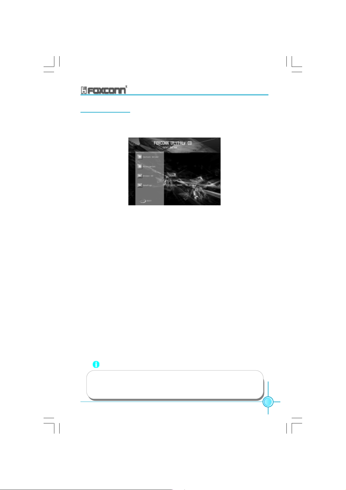
Chapter 4 Driver CD Introduction
Utility CD content
This motherboard comes with one Utility CD. To begin using the CD, simply
insert the CD into your CD-ROM drive. The CD will automatically display the
main menu screen.
Main Menu
1.Install Driver
Using this choice, you can install all the drivers for your motherboard. You
should install the drivers in order, and you need to restart your computer
after the drivers all installed.
A. Chipset Software B. IAA RAID (optional)
C. USB 2.0 Driver D. LAN Driver
E. Audio Driver F. Sil3112 SATARaid
G. DirectX
2.Accessories
Use this option to install additional software programs.
A. SuperUtility B. Adobe Reader
C. Norton Internet Security 2004
3.Browse CD
Click here to browse CD content.
4. Homepage
Click here to visit Foxconn motherboard homepage.
Note:
1. Install the latest patch first if your OS is Windows XP or Windows
2000.
2. Follow the CD screen order to install your motherboard drivers.
875A02 User Manual
69
Page 78
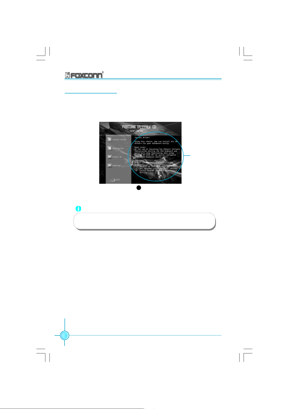
Chapter 4 Driver CD Introduction
Start to Install drivers
Select <Install Driver>, and click to enter the install driver screen. You can
select the driver that you want to install and begin the setup steps.
Read this guide
1
Note:
70
The following setup steps are based on Windows XP environment.
There may be some differences with other operating systems.
875A02 User Manual
Page 79

Chapter 4 Driver CD Introduction
Install Chipset Software
Select <Install Driver> from the main menu and enter the main driver setup
menu (as shown in fig. 1). Click <Chipset Software> to start the installation.
Click here
Click here
1
Click here
4
Click here
5
2
Click here
3
875A02 User Manual
71
Page 80

Chapter 4 Driver CD Introduction
Install IAA-RAID (optional)
From the main menu, select <Install Driver> as shown in following fig. 1.
click <IAA RAID> to start the setup.
Note: IAA RAID is only applicable for the ICH5R chipset.
Click here
1 2
Click here
72
Click here
Click here
5 6
875A02 User Manual
Click here
34
Click here
Click here
Page 81

Chapter 4 Driver CD Introduction
Install USB 2.0 Driver
From the main menu, select <Install Driver> as shown in following fig. 1. Click
<USB 2.0 Driver> to open the USB 2.0 setup window. Please read the setup
directions carefully and select the installation method corresponding to the
operating system that you are currently using.
Read this guide
1
Note:
Use of USB 2.0 requires the support of your operating system. If
you are using Windows 98 or Windows Me, you will need to upgrade your operating system to use USB2.0.
875A02 User Manual
73
Page 82

Chapter 4 Driver CD Introduction
Install LAN Driver (For Realtek 10/100/1000M LAN)
From the main menu, select <Install Driver> as shown in fig. 1. click <LAN
Driver> to start the setup.
Click here
1
Click here
2
Click here
3
74
875A02 User Manual
Page 83

Chapter 4 Driver CD Introduction
Install and Use 4- or 6- Channel Audio Function
This motherboard integrates Realtek ALC650 chip, provides 6-channel audio output, including 2 front speakers, 2 rear speakers, one central speaker,
and one subwoofer. ALC650 can connect 4 or 6 audio boxes to get a better
surround sound effect. This chapter tells you how to install and use these
audio functions.
Content:
1).Install audio driver 2).Use 4-/6- channel audio
functions
3).Test the connected audio boxes 4).Play Karaoke
1).Install Audio Driver
Before using the 4-/6- channel audio functions, you must first install the
driver for the Realtek ALC650 chip. Install the driver according to the
procedure described below:
Click here
1
875A02 User Manual
Click here
2
Click here
3
75
Page 84

Chapter 4 Driver CD Introduction
2).Use 4-/6- Channel Audio Functions
After installing the driver, you can use the 4-/6- channel functions. First,
connect 4 or 6 speakers corresponding to the audio interfaces and then
select the 4 or 6 audio settings in the software.
Connect Audio Box
In order to use the multi-channel function, you must connect several
speakers to the system. You must connect the same number of speakers
as channels selected in the software. The audio interface on the rear
panel can only support 2-channel analog audio output function. When
you select the correct settings in the software, the audio interface on the
rear panel automatically changes into a 4-/6- channel analog audio
interface. Please refer to “How to Select 4- or 6- Channel Setting” at the
end of this chapter for more setting information.
Ensure all speakers are connected to the Line Out interfaces. Use the
interface on the rear panel to use 2-, 4- and 6- channel configuration,
described as follows.
2-Channel Analog Audio Interface
Line In
Line Out (front channels)
Microphone
Description: all Line Out, Line In and Microphone functions exist in 2channel mode.
4-Channel Analog Audio Interface
Line Out (rear channels)
Line Out (front channels)
Microphone
Description: in the 4-channel setting, Line In is changed to Line Out function.
76
875A02 User Manual
Page 85

Chapter 4 Driver CD Introduction
6-Channel Analog Audio Output
Line Out (rear channels)
Line Out (front channels)
Line Out (central and woof channels)
Description: in the 6-channel setting, Line In and Microphone are changed to
Line Out function.
Digital Audio Output
SPDIF CABLE
or
Coaxial SPDIF jack
The blank pin of the SPDIF connection cable corresponds to the 9th pin of the
6CH_Bracket.
Description: for digital audio output, use the provided SPDIF interface. Connect the coaxial SPDIF joint to the coaxial SPDIF jack.
875A02 User Manual
6CH_BRACKET CABLE (Optinal)
77
Page 86

Chapter 4 Driver CD Introduction
Select 4- Or 6- Channel Setting
A. Click the audio icon from the window tray at the bottom of the screen.
B. In the drop-down menu of sound effect item, select the desired
surround sound effect.
Click here the pull-down
menu will appear.
C. Click the Speaker Configuration tab.
78
Click here
875A02 User Manual
Page 87

Chapter 4 Driver CD Introduction
D. The following window appears.
Click here
E. Select the multi-channel operation you perfect from No.of Speaker.
F. Click OK.
3).Testing the Connected Speakers
To ensure 4- or 6-channel audio operation works properly, you may
need to test each connected speaker to make sure every speaker works
properly. If any speaker fails to sound, then check whether the cable is
inserted firmly to the connector or replace the bad speakers with good
ones.
Testing Each Speaker
1. Click the audio icon from the window tray at the bottom of the
screen.
2. Click the Speaker Test tab.
3.
The following window appears.
Center
Front Left
Rear Left
Subwoofer
875A02 User Manual
Front Right
Rear Right
79
Page 88

Chapter 4 Driver CD Introduction
4.Select the speaker which you want to test by clicking it.
Note: if you select “6-channel mode for 5.1 speaker output” from the “Speaker
configuration” list, six speakers will appear in the “Speaker Testing”
window. If you select “4-Channel mode for 4 speaker output”, only four
will appear.
4).Play Karaoke
The Karaoke function will automatically remove the vocals from a track,
leaving just the melody for you to sing over. This function can be used in 2channel mode. Before playing Karaoke, you must select 2-channel mode
from the “Speaker configuration” list.
Play Karaoke:
A. Click audio icon in Windows taskbar in the lower-right of the
screen.
B. Ensure that “Sound Effect” is selected.
C. Select “Sound Effect” in “Karaoke”.
80
Click here
D. Click “OK”.
875A02 User Manual
Page 89

Chapter 4 Driver CD Introduction
Install Sil3112 SATARaid
From the main menu, select <Install Driver> as shown in following fig. 1. Click
<Sil3112 SATARaid> to open the Sil3112 SATARaid setup window. Please read
the setup directions carefully and select the installation method corresponding
to the operating system that you are currently using.
Note: Sil3112 SATARaid is only applicable for the Silicon 3112A
controller.
1
875A02 User Manual
81
Page 90

Chapter 4 Driver CD Introduction
Install DirectX
From the main menu, select <Install Driver> (as shown in following fig. 1), and
click <DirectX 9.0b> to start the setup.
Click here
Click here
1
2
82
4
Click here
3
Click here
875A02 User Manual
Page 91

Chapter 4 Driver CD Introduction
Install Norton Internet Security 2004
From the main menu, select <Accessories> as shown in following fig. 1.
Click <Norton Internet Security 2004> to start the setup.
Click here
Click here
Click here
1 2
4 3
Click here
5 6
Click here
Note:
If your system is Windows 98 or Window ME, please make sure that
your Internet Explorer version is 5.01 with service pack 2 or higher.
875A02 User Manual
83
Page 92

Chapter
This chapter introduces the pertain to software.
Chapter 4 Driver CD Introduction
5
5
This chapter includes the following information:
SuperStep
SuperLogo
SuperUpdate
84
875A02 User Manual
Page 93

Chapter 5 Directions for Bundled Software
SuperStep
SuperStep is a utility that allows users to change the frequency of the CPU. It
also displays system health introduction including CPU temperature, CPU FAN,
CPU voltage, and PCI/AGP clock.
SuperStep features:
1. Supports Win98SE, WinME, Win2000 and WinXP.
2. Automatic alarm mechanism when system runs irregularly
3. Adjusts the CPU frequency to speed up your system and achieve better
system performance.
4. Simple and easy to operate, with a user-friendly graphics interface.
Using the SuperStep:
Go to Fan page System Fan1 speed
CPU Fan
speed
Adjust CPU
Fan warning
criteria
Adjust system
Fan1 warning
criteria
Reset the
warning criteria
to default
settings
875A02 User Manual
Link to FOXCONN Website
Exit Program
Minimize Window
SuperStep on-line Help
About SuperStep
Apply the adjustments
85
Page 94
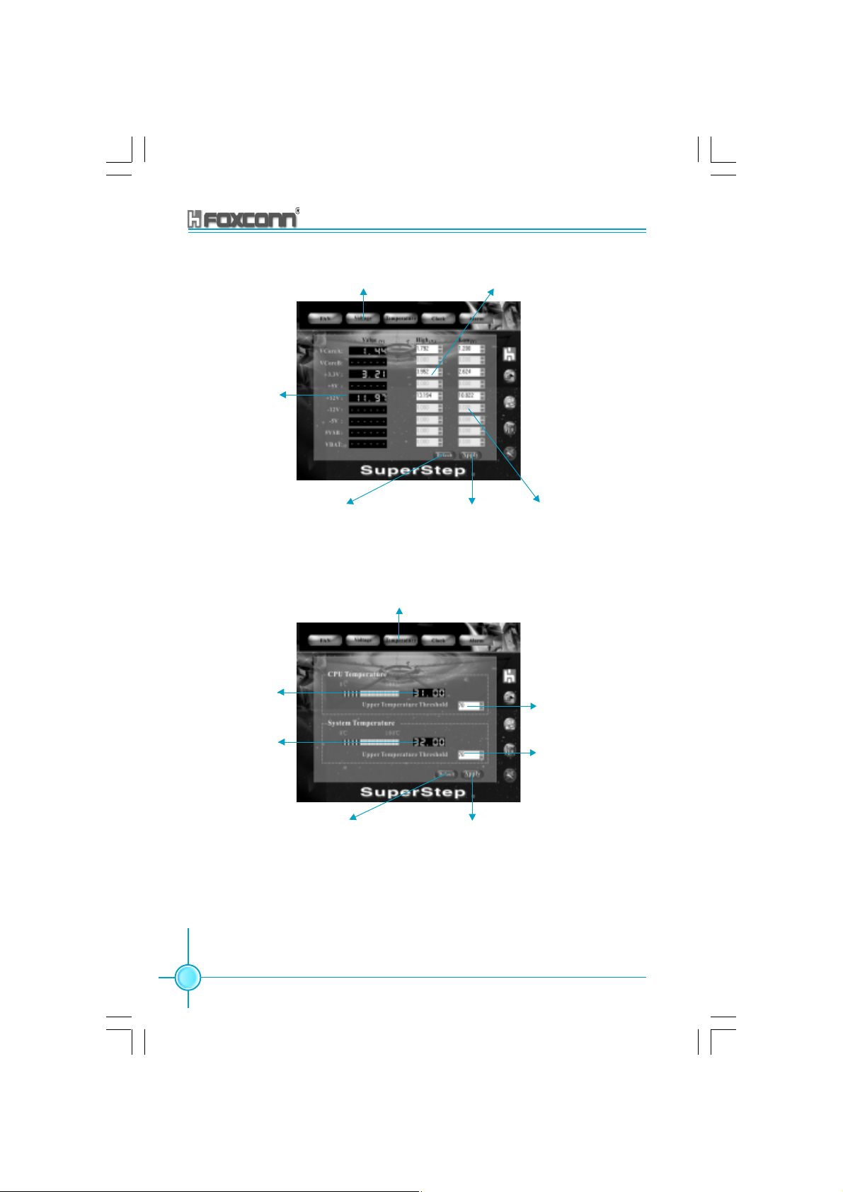
Chapter 5 Directions for Bundled Software
Current voltage
readings
Go to Voltage
page
Reset the warning
criteria to default
settings
Go to Temperature page
Adjust voltages warning
criteria (upper limit)
Apply the
adjustments
Adjust voltages
warning criteria
(lower limit)
Current CPU
Temperature
Current system
Temperature
86
Reset the warning criteria to
default settings
875A02 User Manual
Adjust CPU temperature warning
criteria
Adjust system
temperature
warning criteria
Apply the adjustments
Page 95

Chapter 5 Directions for Bundled Software
Go to Clock page
Current CPU
Clock
Adjust the
CPU Ratio
Reset to the default
settings
Current AGP clock
Current PCI clock
Adjust the CPU
FSB
Apply the adjustments
Go to setting page
Check for the
system to automatically provide
warning message
Reset to the
default settings
875A02 User Manual
Apply the
changes
87
Page 96

Chapter 5 Directions for Bundled Software
SuperLogo
SuperLogo is a Windows utility that allows users to change the BIOS sign on
logo. The utility is able to replace and backup the BIOS logo, and update and
backup the BIOS image within the Windows environment.
SuperLogo features:
1. Supports Win2000 and WinXP.
2. Supports 4Mb size flash parts, flash write method is independent with flash
type.
3. Simple and easy to operate, with a user-friendly graphics interface.
4. Supports BMP and JPEG graphic format files. The best color is 16 or 256
colors. The best resolution is 136x84 for top-right logo and 640x480 or 800x600
for full screen logo.
Using the SuperLogo:
Go to ROM Info page
88
Display the Flash Information
Link to Foxconn website
Exit Program
Minimize Window
SuperLogo on-line Help
About SuperLogo
875A02 User Manual
Page 97

Full screen mode
Top-Right mode
Chapter 5 Directions for Bundled Software
Go to Change Logo page
Boot without logo
BIOS image
file location
Follow the Wizard
to complete the
logo update
Go to Update BIOS page
Browse a BIN file
for updating BIOS
Follow the Wizard
to complete the
BIOS function
Go to Backup page
Backup whole
BIOS image
875A02 User Manual
Backup Logo
Follow the Wizard
to complete the
backup function
89
Page 98

Chapter 5 Directions for Bundled Software
SuperUpdate
SuperUpdate is a Windows utility that allows users to backup and upgrade the
system BIOS.
SuperUpdate features:
1.Supports Win2000 and WinXP.
2.Supports 4Mb size flash parts; flash write method is independent of flash type.
3.Simple and easy to operate, with a user-friendly graphics interface.
Using SuperUpdate:
Browse BIOS bin file
from local HDD
90
Perform the BIOS update
from local image
Upgrating BIOS via
internet automatically
875A02 User Manual
Link to FOXCONN Website
Exit Program
Minimize Window
SuperUpdate on-line Help
About SuperUpdate
Backup system
BIOS to an image
file
Page 99

Chapter 5 Directions for Bundled Software
Update BIOS from local image:
1. Click <Backup> to backup the current BIOS to an image file.
2. Click <Load> to load the BIOS file.
875A02 User Manual
91
Page 100
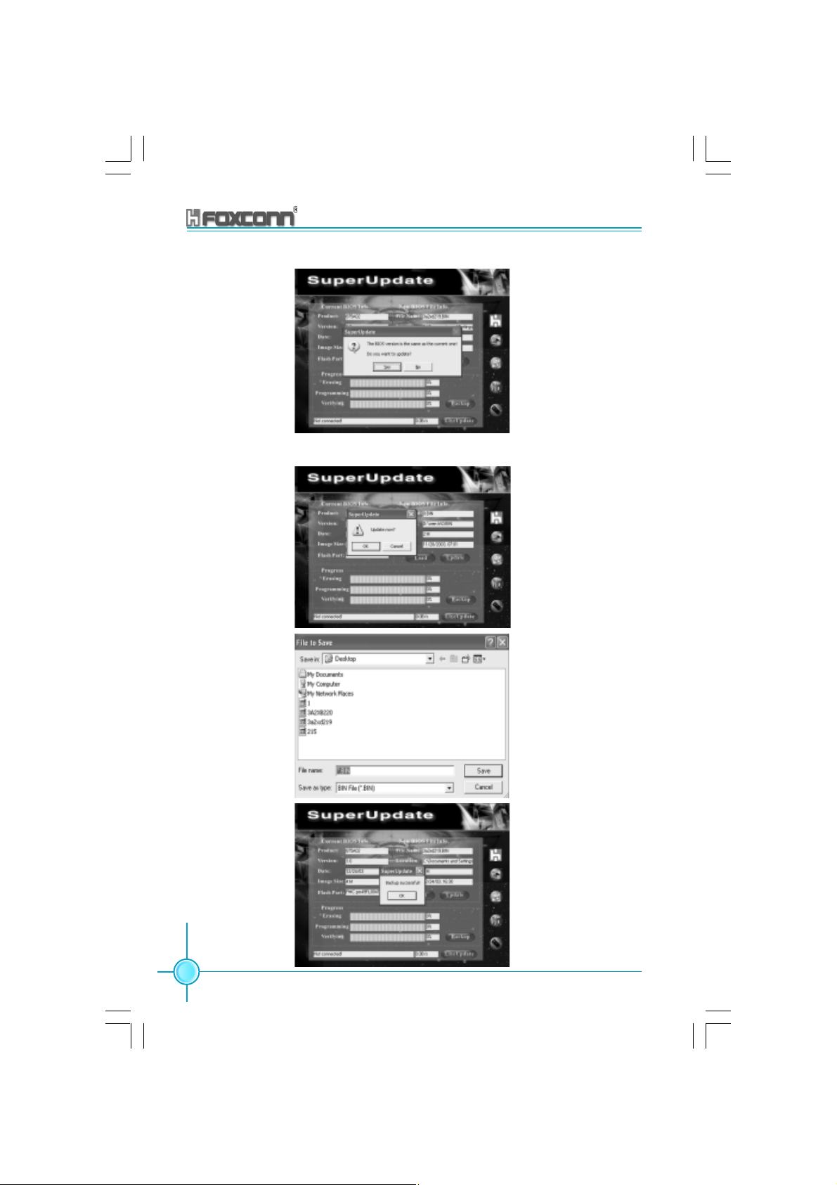
3. Click <Update>.
4. Click <Yes>.
Chapter 5 Directions for Bundled Software
92
875A02 User Manual
 Loading...