

Page 1

Statement:
This manual is the intellectual property of Foxconn, Inc. Although the information in this manual may be changed or modified at any time, Foxconn does not
obligate itself to inform the user of these changes. Additionally, Foxconn does not
accept responsibility for any direct or indirect accident relating with the use of this
manual.
Trademark:
All trademarks are the property of their respective owners.
Intel® and Pentium® are registered trademarks of Intel Corporation.
PS/2 and OS/2 is the registered trademarks of IBM, Inc.
Windows® 95/98/2000/NT/XP is the registered trademark of Microsoft.
Award® is the registered trademark of Award, Inc.
Version:
User manual V1.0 in English for 865A05 series
P/N:91-181-613-11-41
Symbol description:
Note: refers to important information that can help you to use motherboard
better.
Attention: indicates that it may damage hardware or cause data loss,
and tells you how to avoid such problems.
Warning: means that a potential risk of property damage or physical
injury exists.
More information:
If you want more information about our products, please visit Foxconn’s
website: www.foxconnchannel.com
Page 2

Declaration of conformity
HON HAI PRECISION INDUSTRY COMPANY LTD
66 , CHUNG SHAN RD., TU-CHENG INDUSTRIAL DISTRICT,
TAIPEI HSIEN, TAIWAN, R.O.C.
declares that the product
Mainboard
865A05 G/P/PE/GV series
is in conformity with
(reference to the specification under which conformity is declared in
accordance with 89/336 EEC-EMC Directive)
þ EN 55022/A1: 2000 Limits and methods of measurements of radio disturbance
characteristics of information technology equipment
þ EN 61000-3-2/A14:2000 Electromagnetic compatibility (EMC)
Part 3: Limits
Section 2: Limits for harmonic current emissions
(equipment input current <= 16A per phase)
þ EN 61000-3-3/A1:2001 Electromagnetic compatibility (EMC)
Part 3: Limits
Section 2: Limits of voltage fluctuations and flicker in low-voltage
supply systems for equipment with rated current <= 16A
þ EN 55024/A1:2001 Information technology equipment-Immunity characteristics limits
and methods of measurement
Signature : Place / Date : TAIPEI/2003
Printed Name : James Liang Position/ Title : Assistant President
Page 3

Declaration of conformity
Trade Name: PCE Industry Inc.
Model Name: 865A05 G/P/PE/GV
Responsible Party: PCE Industry Inc.
Address: 458 E. Lambert Rd.
Fullerton, CA 92835
Telephone: 714-738-8868
Facsimile: 714-738-8838
Equipment Classification: FCC Class B Subassembly
Type of Product: Mainboard
Manufacturer: HON HAI PRECISION INDUSTRY
COMPANY LTD
Address: 66 , CHUNG SHAN RD., TU-CHENG
INDUSTRIAL DISTRICT, TAIPEI HSIEN,
TAIWAN, R.O.C.
Supplementary Information:
This device complies with Part 15 of the FCC Rules. Operation is subject to the follow-
ing two conditions : (1) this device may not cause harmful interference, and (2) this
device must accept any interference received, including interference that may cause
undesired operation.
Tested to comply with FCC standards.
Signature : Date : 2003
Page 4

Table of Contents
Chapter
Main Features...........................................................................................2
865A05 Layout.........................................................................................5
Chapter
CPU...........................................................................................................7
Memory.....................................................................................................9
Power Supply.........................................................................................10
Rear Panel..............................................................................................11
Connectors.............................................................................................13
Slots.......................................................................................................19
Jumpers..................................................................................................21
Chapter
Enter BIOS Setup.....................................................................................24
Main menu...............................................................................................24
Standard CMOS Features........................................................................26
BIOS Features Setup...............................................................................29
Advanced BIOS Features........................................................................30
Advanced Chipset Features....................................................................33
Integrated Peripherals.............................................................................35
Power Management Setup.......................................................................40
PnP/PCI Configuration..............................................................................43
PC Health Status......................................................................................44
Frequency/Voltage Control......................................................................45
Load Fail-Safe Defaults...........................................................................46
Load Optimized Defaults..........................................................................46
Set Supervisor/User Password...............................................................46
Save & Exit Setup...................................................................................47
Exit Without Saving.................................................................................47
1
1
2
2
3
3
Product Introduction
Installation Instructions
BIOS Description
Page 5

Table of Contents
Chapter
Utility CD content.....................................................................................49
Start to install Driver................................................................................50
Install Chipset Software..........................................................................51
Install DirectX 9.0b..................................................................................52
Install IAA-RAID Setup (optional).............................................................53
Install VGA Driver (optional)....................................................................54
Install USB2.0 Driver................................................................................55
Using 4-/6-channel Audio........................................................................57
Chapter
SuperStep...............................................................................................63
SuperLogo..............................................................................................66
SuperUpdate...........................................................................................69
Chapter
SuperSpeed............................................................................................71
SuperBoot...............................................................................................73
SuperBIOS-Protect..................................................................................74
SuperRecovery.......................................................................................75
4
4
5
5
6
6
Driver CD Introduction
Directions for Bundled Software
Special BIOS Feature
Page 6

Warning:
1.Attach the CPU and heatsink using silica gel to ensure full contact.
2.It is suggested to select high-quality, certified fans in order to avoid
damage to the motherboard and CPU due high temperatures.
3.Never turn on the machine if the CPU fan is not properly installed.
4.Ensure that the DC power supply is turned off before inserting or removing expansion cards or other peripherals, especially when you
insert or remove a memory module. Failure to switch off the DC
power supply may result in serious damage to your system or memory
module.
Warning:
We cannot guarantee that your system will operate normally while
over-clocked. Normal operation depends on the over-clock capacity
of your device.
Attention:
Since BIOS programs are upgraded from time to time, the BIOS
description in this manual is just for reference. We do not guarantee
that the content of this manual will remain consistent with the actual BIOS version at any given time in the future.
Attention:
The pictures of objects used in this manual are just for your reference.
Please refer to the physical motherboard.
Page 7

Chapter
Thank you for your buying Foxconn’s 865A05 series
motherboard. This series of motherboard is one of our new
products, and offers superior performance, reliability and
quality, at a reasonable price. This motherboard adopts
the advanced Intel® 865 G/P/PE/GV+ICH5/5R chipset, providing users a computer platform with a high integrationcompatibility-performance price ratio.
This chapter includes the following information:
1
1
v Motherboard Features
v Motherboard Layout
Page 8
Chapter 1 Product Introduction
Main Features
Size:
·ATX form factor of 11.6” x 7.87”
Microprocessor:
·Supports Intel® Pentium®4 Socket 478 (Willamette/Northwood/Prescott) proces
sors
·Supports Intel® Celeron® Socket 478 (Willamette/Northwood) processors
·Supports FSB at 400MHz/533MHz/800MHz
·Supports Hyper-Threading technology
Chipset:
·Intel® Springdale Chipset: Intel® 865G/P/PE/GV (NorthBridge) +ICH5/5R (SouthBridge)
System Memory:
·Provides two 184-pin DDR DIMM Sockets
·Supports DDR266/DDR333/DDR400
·Supports 128/256/512MB/1GB technology up to 2GB
·Supports Dual-channel DDR
Attention:
1. Use the same memory modules for Dual-Channel.
2. The memory operating frequency is 320MHz while FSB800 CPU
works with DDR333.
USB 2.0 Port:
·Supports hot-Plug
·Six USB 2.0 ports (four rear panel ports, one onboard USB header providing
two extra ports)
·Supports wake-up from S1 mode
·Supports USB 2.0 Protocol, 480 Mbps transmission rate
Onboard IDE:
·Supports up to four independent drives
·Supports Ultra ATA100/66/33
·Two IDE interfaces can connect with four IDE units, including hard disk and CD-ROM/
DVD-ROM
2
865A05 G/P/PE/GV User Manual
Page 9

Chapter 1 Product Introduction
Onboard I/O:
·One FDD interface; supports two 3.5” or 5.25” FDDs with 360K/720K/1.2M/1.44M/
2.88M format
·One high-speed 16550 COM interface with 16-byte FIFO buffer (COM1)
·One infrared interface
·Four USB interfaces (with 6 ports supported at most), one 1394 interface (with
2 ports supported at most) (Optional)
·One parallel interface supporting SPP/EPP/ECP modes
·All I/O ports can be enabled/disabled in the BIOS setup
Onboard Serial ATA:
·150MB/s transfer rate
·Supports two S-ATA devices, such as HDD etc.
Onboard Audio:
·AC’ 97 2.3 Specification Compliant
·Supports S/PDIF output/input
·Onboard Line-in jack, Microphone-in jack, Line-out jack
·Supports 5.1 channels audio (setting via software)
Onboard Graphics :
·Supports integrated VGA display functions (Intel Extreme Graphics) (Supported
on 865A05G/GV only)
·Supports external AGP3.0/2.0 specification; supports 4X/8X display cards
(Supportedon 865A05G/PE only)
BIOS:
·Licensed advanced AWARD (Phoenix) BIOS, supports flash ROM, Plug-andPlay
·Supports IDE CD-ROM, SCSI HDD or USB device boot up
Green Function:
·Supports ACPI (Advanced Configuration and Power Interface)
·Supports S0 (normal), S1 (power on suspend), S4 (suspend to disk-depends
on OS), and S5 (soft-off)
Expansion Slots:
· PCI slots
· AGP slot (Supported on 865A05 G/P/PE only)
865A05 G/P/PE/GV User Manual
3
Page 10

Chapter 1 Product Introduction
Advanced Features:
·PCI 2.3 Specification Compliant
·Supports Windows98/2000/ME/XP soft-off
·Supports Wake-on-LAN function
·Supports PC Health function (capable of monitoring system voltage, CPU,
system temperature, and fan speed)
4
865A05 G/P/PE/GV User Manual
Page 11
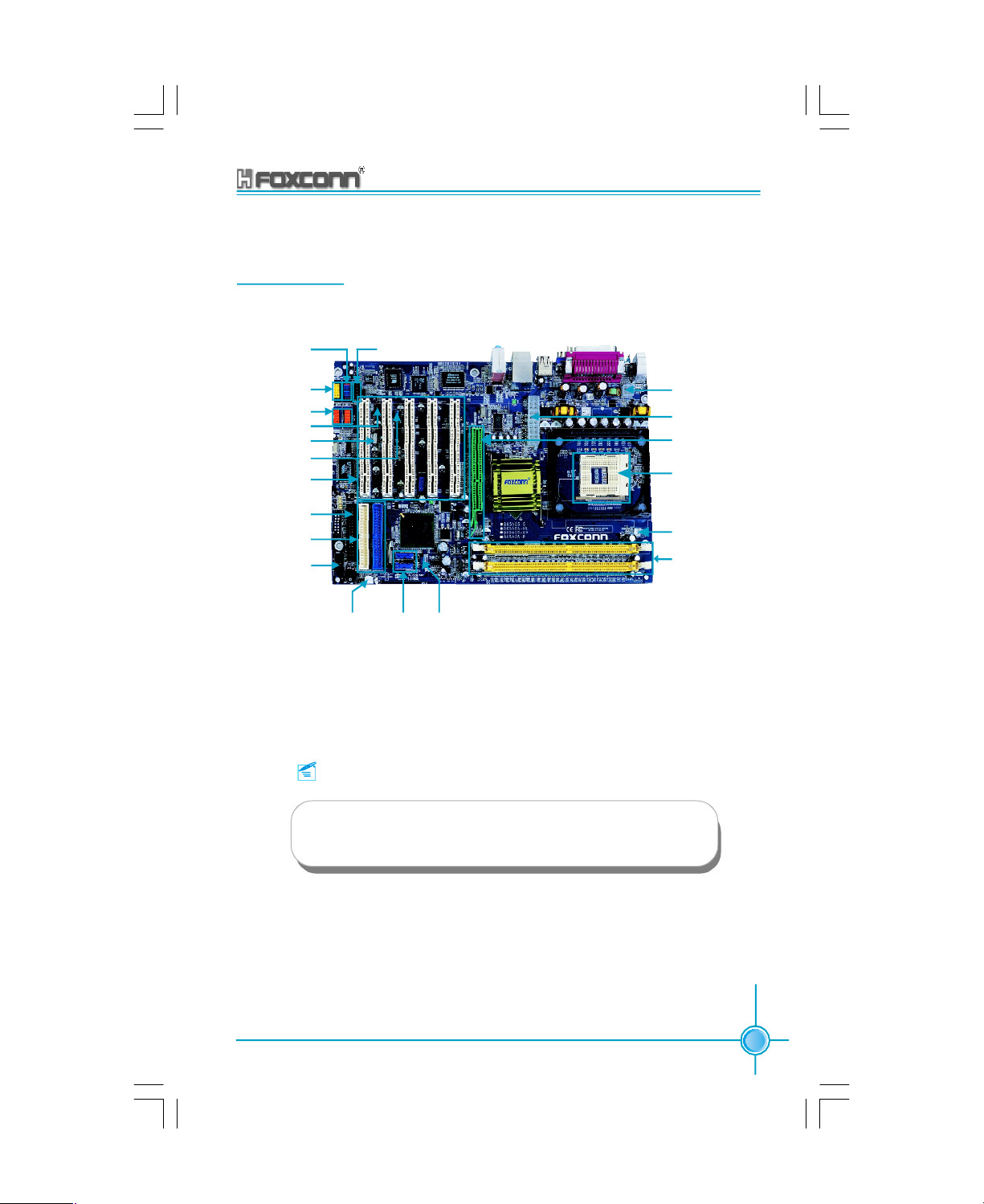
865A05 Layout
Chapter 1 Product Introduction
Front_AUDIO
Connector
SPDIF Connector
1394_HDER1/2
IrDA Connector
WAKE ON LAN
BIOS LOCK
PCI Slots
Floppy Connector
ATA 33/66/100
IDE Connectors
Front Panel
Connector
SYS FAN
Connector
Remark:
CD-IN Connector
JP1 Clear
SATA
Connectors
CMOS Jumper
12V ATX Power
Connector
ATX Power
Connector
AGP Slot (Optional)
Socket 478
CPU FAN
Connector
DIMMs
The above motherboard layout is provided for reference
only; please refer to the physical motherboard.
865A05 G/P/PE/GV User Manual
5
Page 12
Chapter
This chapter introduces the hardware installation process,
including the installation of the CPU, memory, power
supply, slots, rear panel and pin headers, and the mounting of jumpers. Caution should be exercised during the
installation of these modules. Please refer to the
motherboard layout prior to any installation and read the
contents in this chapter carefully.
2
2
Chapter 1 Product Introduction
This chapter includes the following information:
v CPU
v Memory
v Power Supply
v Rear Panel
v Interface
v Slots
v Jumpers
6
865A05 G/P/PE/GV User Manual
Page 13

Chapter 2 Installation Instructions
CPU
This motherboard use socket 478 CPUs with a FSB 400/533/800MHz and HyperThreading technology.
Remark:
Please make sure to have your CPU with the overheat-proof radiating flange and cooling fan. Please contact with the distributor if your
CPU has no such overheat-proof radiating flange and cooling fan,
and make such units installed properly prior to the start-up of your
computer.
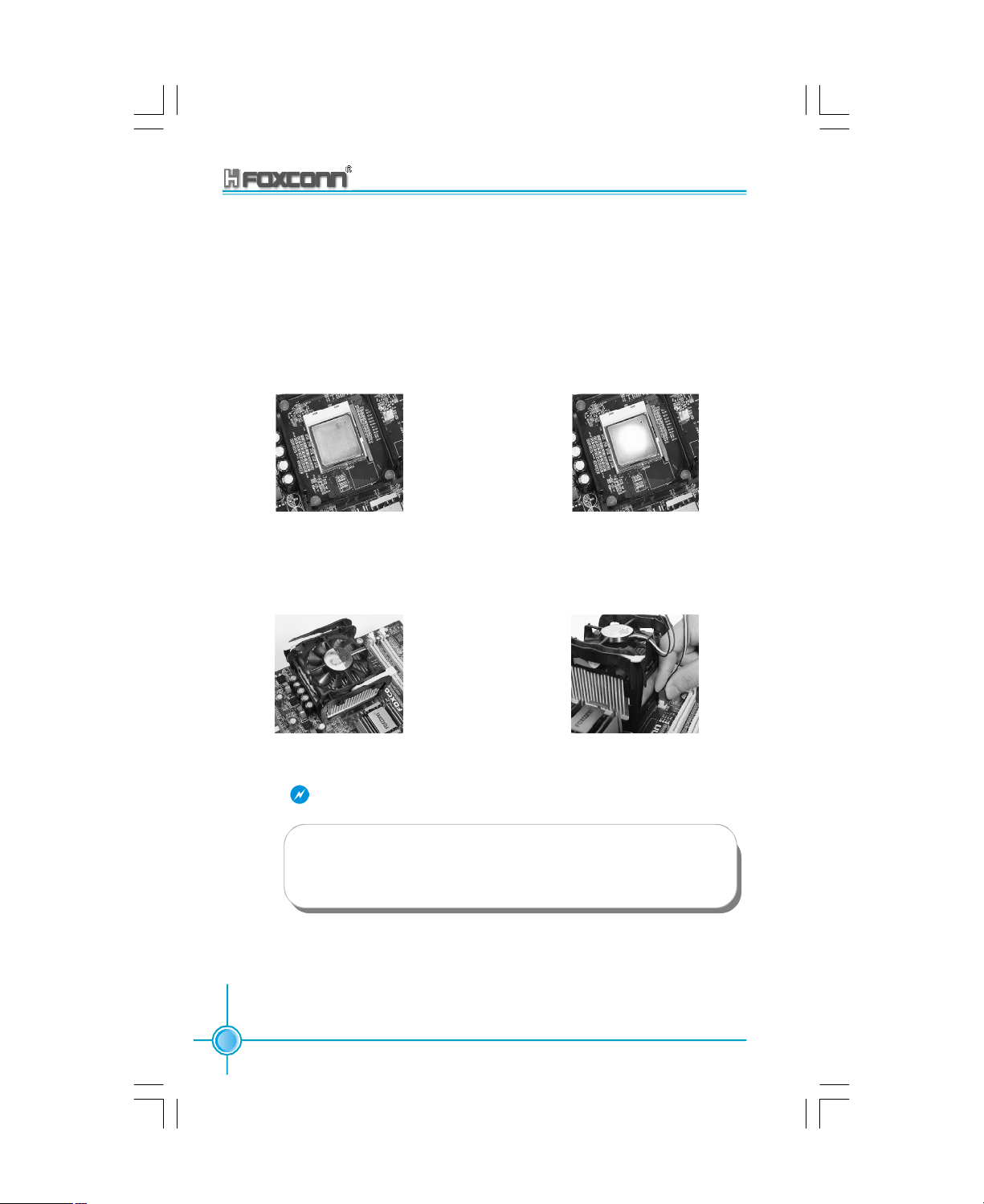
Installation of CPU
NOTE: The CPU pins must be properly
aligned with the slots in the socket, oth-
erwise the CPU may be damaged.
1. Lift the retention arm from the
socketuntil it is in a position of 90
from the base of the socket.
2.Locate the gold triangle on the
CPU. Align the triangle to the gap
in the base of the socket and insert
the CPU into the socket. Make
sure that the CPU’s pins are
aligned properly with the slots
in the socket. Then lower the retention
arm to secure the CPU in place.
865A05 G/P/PE/GV User Manual
o
CPU pin 1
CPU socket level
up to 90 degree
Socket cut edge
Press down the CPU
socket level
7
Page 14
Chapter 2 Installation Instructions
Installation of CPU Fan
New technology allows processors to run at higher and higher frequencies. To
avoid problems arising from high-speed operation, for example, over-heating,
you need to install the proper cooler and fan. Install the cooler/fan according to
the following procedures:
1.Locate the CPU slot and base for fan
on the motherboard.
3. Attach the fan to the base.
Warning:
2.Apply a little silica gel to the back of
the CPU.
4.Connect the power fan’s power cable
to the appropriate 3-pin terminal on
the motherboard.
Excessive temperatures will severely damage the CPU and system.
Therefore, make sure that the cooling fan works normally at all times
in order to prevent overheating and damage to the CPU.
8
865A05 G/P/PE/GV User Manual
Page 15

Chapter 2 Installation Instructions
Memory
This motherboard includes two 184-pin slots with 2.6V DDR DIMM, so you can
install DDR 400/333/266 memory bank. You must install at least one memory
bank to ensure normal operation.
Installation of DDR Memory
1.There is only one gap in the center of the DIMM slot, and the memory module can
be fixed in one direction only.
2.Align the memory module to the DIMM slot, and insert the module vertically into
the DIMM slot.
3.The plastic clips at both sides of the DIMM slot will lock automatically.
865A05 G/P/PE/GV User Manual
9
Page 16

Chapter 2 Installation Instructions
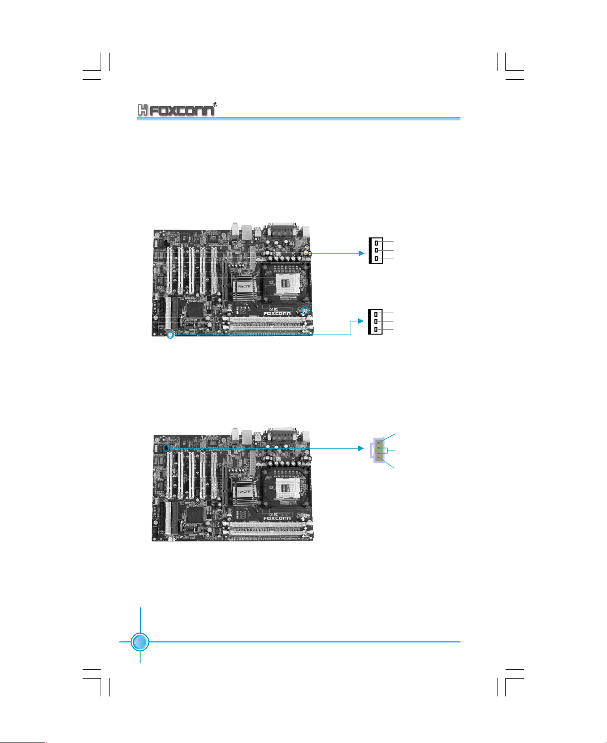
Power Supply
This motherboard uses an ATX power supply. In order to avoid damaging any
devices, make sure that they have been installed properly prior to connecting the
power supply.
ATX 12V Power Connector: CN25
CN25 is the ATX power supply connector. Make sure that the power supply cable
and pins are properly aligned with the connector on the motherboard. Firmly plug
the power supply cable into the connector and make sure it is secure.
ATX Power Connector: CN11
The ATX power supply connects to CN11 and provides power to the CPU.
ATX 12V Power Terminal
12V
GND
4 3
12V
GND
2 1
ATX 20-pin Power Terminal
5V
5V
20
10
12V
5VSB
GND
GND
-5V GND PS-ON -12V
Pw-OK
GND
5V
5V
GND
GND
3.3V
GND 3.3V
Attention:
You have to press the power button for more than four seconds if you
change the default “Instant-off” setting to “Delay 4 Sec” for the soft-
off by Power Button option in the BIOS Power Management Setup.
3.3V
11
1
10
865A05 G/P/PE/GV User Manual
Page 17
Chapter 2 Installation Instructions
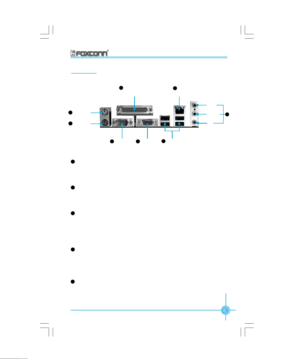
Rear Panel
This motherboard provides the ports as below:
SPP/EPP/ECP Paral-
4
lel Port (Printer Port)
1
PS/2 Mouse
Connector
2
PS/2 Keyboard
Connector
7
(Optional)
LAN Port
Line-in
Line-out
MIC
8
3
COM 1 Port
1
PS/2 Mouse Connector
VGA Port
5
(only for 865G/GV)
6
USB 2.0 Ports
This motherboard includes one standard PS/2 mouse connector. You can connect the PS/2 mouse directly into it.
2
PS/2 Keyboard Connector
This motherboard provides one standard PS/2 keyboard connector. If you select the standard AT keyboard, then you will need a converter to use it.
3
Serial port: COM1
This motherboard provides one 9-pin common adapter for serial port COM1.
This port is the 16550A high-speed communication interface used to transfer
and receive 16-byte FIFO. You can connect the sequential mouse or other se-
quential devices directly to the port.
4
SPP/EPP/ECP Parallel Port (Printer Port)
This motherboard provides one 25-pin mother connector for LPT. The parallel
port is a standard printer port which supports the enhanced parallel port (EPP),
ECP mode, etc.
5
VGA Port (for those supported by 865A05G/GV)
This motherboard integrates the display function, so the display interface can
be connected directly with the VGA port without plugging in the AGP card to
switch over to the monitor.
865A05 G/P/PE/GV User Manual
11
Page 18
Chapter 2 Installation Instructions
6
USB 2.0 Ports
This motherboard includes a group of UHCI for the universal serial bus to connect with USB devices, e.g., keyboard, mouse, or other USB compatible devices.
The USB interface supports PnP function, and USB devices can be plugged into
this interface directly.
7
RJ45 10/100 LAN Port (Optional)
If you have purchased the built-in LAN function, the port will be located on the rear
panel.
8
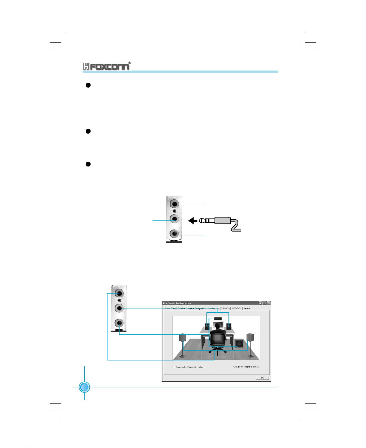
Audio Port
When using a two-channel sound source, the Line-out jack is used to connect to
speakers or headphones; the Line-in port connects to an external CD player,
tape player or other audio devices. The MIC is used to connect to the microphone.
Line In
Line Out
MIC
When using a 6-channel sound source, connect the front speaker to the green
audio output; connect the surround sound speaker to the blue audio input; connect the central speaker/sub woofer to the red MIC input, as shown in the follow-
ing figure:
Blue
Green
Center
Front Right
Rear
Right
Subwoofer
12
Red
Rear
Left
865A05 G/P/PE/GV User Manual
Front Left
Page 19

Chapter 2 Installation Instructions
Connectors
This motherboard includes interfaces for FDD, IDE HDD, SATA, and computer
case, USB, 1394, IR module, CPU/system fan, and others.
FDD
This motherboard includes a standard FDD interface, supporting 360K, 720K, 1.
2M, 1.44M, and 2.88M FDDs.
FDD Interface
HDD Interface: IDE1 & IDE2
This motherboard includes an Ultra DMA 33/66/100 controller, allowing the IDE
interface device to work in PIO mode 0-4, Bus Master, and Ultra DMA 33/66/100
modes. You can use four IDE devices, such as the HDD, CD-ROM, etc. These
adapters support the provided IDE HDD line.
PIDE (Primary IDE Interface)
The first HDD must be connected to the PIDE interface. A master HDD and a slave
HDD can be connected to PIDE. The second HDD must be set as the slave via
the corresponding jumper for HDD.
SIDE (Secondary IDE Interface)
You can connect a master and a slave HDD to SIDE.
Attention:
If you want to connect two HDDs to one HDD line, then the second
HDD must be set as the slave. As to the setting of master/slave
HDD, please refer to the instructions provided for such HDD.
865A05 G/P/PE/GV User Manual
13
Page 20

Chapter 2 Installation Instructions
SIDE
PIDE
Front Panel Connector: CN34
This motherboard includes one connector for connecting the front panel switch
and LED indicator.
1 2
+
+
-
-
HD-LED
RESET
NC
9 10
PWR-LED
PWR-SW
HDD-LED Connector
Attach the connector to the HDD-LED on the front panel of the case; the LED will
flash while the HDD is in operation.
Reset Switch
Attach the connector to the Reset switch on the front panel of the case; the system
will restart when the switch is pressed.
PWR-LED indicator
Attach the connector to the power LED on the front panel of the case. The Power
LED indicates the power supply status, and will be lit during normal system
operation. The Power LED will blink while the system is in the S1 mode, and will
be turned off when the system is in either S5 mode.
14
865A05 G/P/PE/GV User Manual
Page 21

Chapter 2 Installation Instructions
IrDA Infrared Communication Connector: J8
The IrDA infrared transmission allows your computer to send and receive data via
an infrared ray. The relevant parameters for the BIOS “Integrated Peripherals”
should be set prior to using this function.
1
+5V
Empty
IRRX
GND
IRTX
IrDA
Front Panel USB Header: USB_HDER1
This motherboard includes one USB headers. The patch cable can be connected to either the front or rear panel of the case.
NC
GND
D4+
D4-
VCC
USB_HDER 1
Empty
GND
D5+
D5-
VCC
865A05 G/P/PE/GV User Manual
15
Page 22
Chapter 2 Installation Instructions
Fan Header: CPU-FAN, SYS-FAN
There are two fan headers on this motherboard, one for the CPU, and one for the
system. The fans will stop automatically when the system enters energy-saving
mode. The CPU/system fan settings can be adjusted by modifying the settings in
the PC Health section of the BIOS.
GND
+12V
SENSE
GND
+12V
SENSE
CPU-FAN
SYS-FAN
Audio Header: CD_IN
To receive audio input from the CD-ROM, attach its audio connector to the CD_IN
audio headers on the motherboard.
CD_R
GND
CD_L
CD_IN
16
865A05 G/P/PE/GV User Manual
Page 23

Chapter 2 Installation Instructions
Wake-up On LAN Header: WOL
Connect the header to the corresponding online wake-up output on the network
card. The system will wake up from sleep mode when the wake-up signal is sent
to it.
Attention:
1.This function will not work unless a) it is supported by the network card, and b)
the ATX power supply is 5VSB>=720mA.
2.Set the Wake-up by PCI Card to “Enabled” in the Power Management Setup of
BIOS. Save the settings, exit the BIOS, and restart the system to enable the
setting.
+5V standby
GND
Signal for waking up
WOL
S-ATA Headers: CN21, CN22
The S-ATA headers are used to connect the S-ATA devices to the motherboard.
R
T
X
X
R
T
-
-
X
X
+
+
G
G
865A05 G/P/PE/GV User Manual
G
N
D
SATA1/SATA2
N
N
D
D
17
Page 24

Chapter 2 Installation Instructions
Audio Header: FP-AUDIO
The audio port includes two parts – the Front Audio and Rear Audio. Their priority
is sequenced from high to low (Front Audio to Rear Audio). If headphones are
plugged into the front panel of the chassis (using the Front Audio), then the
Speaker Out (Rear Audio) on the rear panel will not work. If you do not want to use
the Front Audio, pins 5, 6, 9, and 10 must be unlocked, and then the signal will be
sent to the rear audio port.
1
MIC AGND
MIC_VCC
R_OUT FR_OUT
NA
L_OUT FL_OUT
Connecting the SPDIF/6CH_BRACKET
The SPDIF/6CH_BRACKET output is capable of providing digital or 6-channel
audio to external speakers, or compressed AC3 data to an external Dolby digital
decoder. This motherboard includes one SPDIF/6CH_BRACKET.
2
A5V
Empty
9 10
FP-AUDIO
18
1
SL_OUT
CEN_OUT
GND
SPDIF_IN
9
SPDIF CABLE
6CH_BRACKET
Attention:
The empty pin of the SPDIF cable should be aligned to pin 9 on
the SPDIF/6CH_BRACKET.
865A05 G/P/PE/GV User Manual
2
SR_OUT
LEFOUT
NA
VCCSPDIF_OUT
AGND
10
Page 25

Chapter 2 Installation Instructions
Slots
This motherboard includes five 32-bit Master PCI bus slots and one AGP slot.
PCI Slots
The expansion cards can be installed in the five PCI slots. When you install or
take out such cards, you must make sure that the power plug has been pulled
out. Please read carefully the instructions provided for such cards, and install
and set the necessary hardware and software for such cards, such as the jumper
or BIOS settings.
PCI Slot
AGP Slot (Accelerated Graphic Port)( only for 865G/P/PE)
An AGP graphic card can be installed in the AGP slot. AGP is an interfacing specification designed to display 3D images. It provides a specialized 66Mhz, 32-bit
channel to allow the graphic controller to directly access the master memory, and
supports 4X and 8X speeds.
AGP Slot
865A05 G/P/PE/GV User Manual
19
Page 26
Chapter 2 Installation Instructions
Warning:
This AGP slot does not support 3.3V AGP cards. The motherboard
may be damaged if a 3.3V AGP card is used. Verify that your AGP
card is not 3.3V and that the golden fingers are not damaged or
dirty.
Installing an expansion card
1.Before installing the expansion card, read the documentation that came with it
and make the necessary hardware settings for the card.
2.Make sure to unplug the power cord before adding or removing expansion cards.
3.Remove the bracket opposite the slot that you intend to use.
4.Align the card connector with the slot and press firmly until the card is completely
seated on the slot.
5.Secure the card to the chassis with the screw you removed earlier.
20
865A05 G/P/PE/GV User Manual
Page 27

Chapter 2 Installation Instructions
Jumpers
The users can change the jumper settings on this motherboard if needed. This
section explains how to use the various functions of this motherboard by changing the jumper settings. Users should read the following contents carefully prior
to modifying any jumper settings.
Description of Jumpers
1.For the jumpers on this motherboard, pin 1 can be identified by the silk-screen printed
“ ” next to it. However, in this manual, pin 1 is simply labeled as “1”.
2.The following table provides some explanation of the jumper pin settings. User
should refer to this when adjusting jumper settings.
Jumper Diagram Definition Description
1
1
1
1
1
1
Clear CMOS Jumper: JP1
This motherboard uses the CMOS RAM to store all the set parameters. The
CMOS can be cleared by removing the CMOS jumper. First, turn off the AC power
supply and quickly connect pins 1 and 2 together using the jumper cap. Then,
return the jumper setting to normal (pins 2 and 3 locked together with the jumper
cap), and turn the AC power supply back on.
1-2 Set pin 1 and pin 2 closed
2-3 Set pin 2 and pin 3 closed
Closed Set the pin closed
Open Set the pin opened
Normal status
(default)
Clear CMOS
1
2
3
1
2
3
Warning:
1.Disconnect the power cable before adjusting the jumper settings.
2.Do not clear the CMOS while the system is turned on.
865A05 G/P/PE/GV User Manual
JP1
21
Page 28

Chapter 2 Installation Instructions
Anti-virus BIOS Write Protect Jumper: JP2
To protect the system BIOS from viruses, this motherboard is designed with a
BIOS write-protection jumper (JP2). Lock pins 2 and 3 on JP2 and disable
SuperBIOS-Protect in the BIOS, and then the BIOS can be flashed. (Note: the
default setting for pins 2 and 3 on JP2 is “unlocked”.)
BIOS Lock
Unlock
(default)
BIOS Lock
Lock
1
2
3
1
2
3
JP2
CPU Model Selection Jumper (J9)
The default status for J9 is Open, which supports the Prescott and Northwood
CPU. If J9 set as Closed, then it supports the Willamette CPU.
1
Closed
Open
(Default)
2
1
2
J 9
22
865A05 G/P/PE/GV User Manual
Page 29

Chapter
This chapter introduces the 865A05 motherboard’s CMOS
Setup program, which allows users to configure optimized system settings.
You have to run the Setup Program when the following cases
occur:
1.An error message appears on the screen during the system
2.You want to change the default CMOS settings.
This chapter includes the following information:
3
3
POST process.
v Enter BIOS Setup
v Main Menus of BIOS Setup
v Setting of Standard CMOS Features
v Setup of BIOS Features
v Setup of Advanced BIOS Features
v Setup of Advanced Chipset Features
v Setup of Integrated Peripherals
v Power Management Setup
v PNP/PCI Configurations
v System Monitoring
v Frequency/Voltage Control
v Load Defaults Set by BIOS
v Load Optimized Defaults
v Set Supervisor/User Password
v Save and Exit
v Exit without Saving
Page 30

Chapter 3 BIOS Description
Enter BIOS Setup
After the computer is powered on, the BIOS will self -diagnose the basic hardware on the motherboard (POST process), set up the time sequence parameters
for hardware, detect the hardware devices, etc.. After the POST process is
completed, control of the system will be transferred to the operating system.
Since the BIOS is the communication bridge between hardware and software,
correctly setting up the BIOS parameters is critical to maintain optimal system
performance. In general, when the computer is turned on and while BIOS is
executing the POST process, the following message will appear in the lower left
corner of the screen:
Press TAB to show POST Screen, DEL to enter SETUP.
If you want to enter the BIOS, you must press the <Del> button within 3-5 seconds
of the appearance of the above message.
Remark:
If you want to enter the BIOS, you must press the <Del> button
within 3-5 seconds of the appearance of the above message.
Main Menu
The main menu allows you to select from the list of setup functions and two exit
choices. Use the arrow keys to select among the items and press <Enter> to
accept or go to the sub-menu.
Main Menu
The items in the BIOS Setup main menu are explained below:
Standard CMOS Features
The basic system configuration can be set up through this menu.
BIOS Features
The general system features can be set up through this menu.
24
865A05 G/P/PE/GV User Manual
Page 31

Chapter 3 BIOS Description
Advanced BIOS Features
The advanced system features can be set up through this menu.
Advanced Chipset Features
The register values for the chipset can be changed through this menu, and the
system performance can be optimized.
Integrated Peripherals
Special settings for peripheral devices can be modified through this menu.
Power Management Setup
The system’s power management setting can be modified through this menu.
PnP/PCI Configurations
The system’s PnP/PCI settings and parameters can be modified through this
menu.
PC Health Status
This will display the current status of your PC.
Frequency/Voltage Control
Frequency and voltage setting can be adjusted through this menu.
Load Fail-Safe Defaults
The default BIOS settings can be loaded through this menu.
Load Optimized Defaults
The optimal performance settings can be loaded through this menu, however,
the stable default values may be affected.
Set Supervisor Password
The supervisor password can be set up through this menu.
Set User Password
The user password can be set up for through this menu.
Save & Exit Setup
Save the change(s) made to the CMOS settings and exit Setup.
Exit Without Saving
Abandon the change(s) made to the CMOS settings and exit Setup.
865A05 G/P/PE/GV User Manual
25
Page 32

Chapter 3 BIOS Description
Standard CMOS Features
This sub-menu is used to set up the standard CMOS features, such as the date,
time, HDD model and so on. Use the arrow keys select the item to set up, and
then use the <PgUp> or <PgDn> keys to choose the setting values
Date
This option allows you to set the desired date (usually as the current date) with
the <day><month><date><year> format.
day weekday from Sun. to Sat., defined by BIOS (read-only).
month month from Jan. to Dec.
date date from 1st to 31st, can be changed by using the keyboard.
year year,set up by users.
Time
This option allows you to set up the desired time (usually as the current time) with
<hour><minute><second> format.
IDE Channel 0/1 Master/Slave (First channel master/slave HDD/sec-
ond master/slave HDD)
You can select this option by pressing the <Enter> key, and the BIOS will detect
the current HDD model. The HDD type can be selected using <PgUP>/<+> or
<PgDn>/<-> . “None” means that no HDD is currently installed; “Auto” means that
the BIOS will automatically detect and set the HDD type after the system is started
up with HDD; when “Manual” is selected and the Access Mode is changed to
CHS, the system will request you to key in the following HDD parameters:
Cylinder number of cylinders Head number of heads
Precompwrite pre-compensation Landing Zone Landing Zone
Sector number of sectors
26
865A05 G/P/PE/GV User Manual
Page 33

Chapter 3 BIOS Description
Award (Phoenix) BIOS can support 3 HDD modes: CHS, LBA and Large or Auto
mode.
CHS For HDD<528MB
LBA For HDD>828MB & supporting LBA (Logical Block Addressing)
Large For HDD>528MB but not supporting LBA
Auto Recommended mode
Drive A/B (FDD A/B)
This option allows you to select the kind of FDD to be installed, including “None”,
[360K, 5.25 in][1.2M, 5.25 in], [720K, 3.5 in], [1.44M, 3.5 in] and [2.88 M, 3.5 in].
Video (Display Card)
The following table is provided for your reference in setting the display mode for
your system.
EGA/ VGA Enhanced Graphics Adapter / Video Graphic Array. For EGA,
VGA, SEGA, SVGA, or PGA monitor adapters.
CGA 40 Color Graphic Adapter, powering up in 40 column mode.
CGA 80 Color Graphic Adapter, powering up in 80 column mode.
MONO Monochrome adapter, including high resolution monochrome
adapters.
Halt On
This option can be used to set your PC to stop if any error(s) occur after the
system has started.
All errors The system will stop and display the prompt whenever
an error is detected.
No errors The system will start as usual even if an error is
detected
All, But Keyboard The system will stop when any error other than keyboard
error occurs
All, But Diskette The system will stop when any error other than disk
error occurs
All, But Disk/Key The system will stop when any error other than keyboard
or disk error occurs
865A05 G/P/PE/GV User Manual
27
Page 34

Chapter 3 BIOS Description
Memory
This displays the system storage information detected by BIOS during the Power
on self test (POST).
Base Memory The basic memory capacity loaded in the system
is determined by BIOS during the POST.
Extended Memory The extended memory capacity is determined by
BIOS during the POST.
Total Memory The total of all memory capacities.
28
865A05 G/P/PE/GV User Manual
Page 35

Chapter 3 BIOS Description
BIOS Features Setup
BIOS Features Menu
v[SuperBoot] SuperBoot (Default: Disabled)
SuperBoot allows system-relevant information to be stored in CMOS upon the
first normal startup of your PC, and the relevant parameters will be restored to
help the system start up more quickly on each subsequent startup. The available
setting values are: Disabled and Enabled.
Note: Disabled and Enabled have the same meaning if in the following sections
of this Manual.
v[SuperBIOS-Protect] SuperBIOS-Protect (Default: Disabled)
SuperBIOS-Protect Funtion protects PC from viruses,e.g. CIH, by using a HW/
SW double BIOS lock technology. The available setting values are: Disabled
andEnabled.
v[SuperRecovery] SuperRecovery Hotkey (Default: LSHIFT+F12)
SuperRecovery provides the users with an excellent data protection and HDD
recovery function. There are 12 optional settings, and the default setting is
LSHIFT+F12.
v[SuperSpeed] CPU Clock (Depending on the specification of the CPU)
The conventional over-clock method uses the jumpers on the motherboard,
and it is both troublesome and apt to errors. By using SuperSpeed, a CPU can
be overclocked by keying in the desired, with a setting range of 100-233MHz.
Warning:
The operating frequency of a CPU should be set with care, and we
recommend that you do not set the CPU frequency beyond its normal operating range.We shall not be responsible for any damage
that occurs due to over-clocking.
865A05 G/P/PE/GV User Manual
29
Page 36

Chapter 3 BIOS Description
Advanced BIOS Features
Advanced BIOS Features Menu
vHard Disk Boot Priority
This option is used to select the priority for HDD startup. After pressing <Enter>,
you can select the HDD using the <PageUp>/<PageDn> or Up/Down arrow
keys, and change the HDD priority using <+> or <->; you can exit this menu by
pressing <Esc>.
vCPU L1 & L2 Cache (Default: Enabled)
This option is used to turn on or off the L1 and L2 CPU cache. The available
setting values are: Disabled and Enabled.
vHyper-Threading Technology (Default: Enabled)
This option is used to turn on or off the Hyper-threading function of the CPU.
The available setting values are: Disabled and Enabled.
Note: This function will not be displayed until a CPU that supports Hyper-Threading
has been installed.
vQuick Power On Self Test (Default: Enabled)
With this function enabled, the system will skip the normal test while starting
up, therefore reducing the overall start up time. The available setting values
are: Disabled and Enabled.
vFirst/Second/Third Boot Device (Default: Floppy/Hard Disk/CDROM)
This option allows you to set the boot device secquence. The available setting
values are: Floppy, LS120, Hard Disk, CDROM, ZIP100, USB-FDD, USB-ZIP,
USB-CDROM, USB-HDD, LAN, and Disabled.
vBoot Other Device (Default: Enabled)
With this function set to Enabled, the system will to boot from some other devices if the first/second/third starting devices failed.
30
865A05 G/P/PE/GV User Manual
Page 37

Chapter 3 BIOS Description
vSwap Floppy Drive (Default: Disabled)
If it set as Enabled, the label of FDD A and B can be exchanged. The available
setting values are: Disabled and Enabled.
vBoot Up Floppy Seek (Default: Enabled)
If it set as Enabled, BIOS will activate the floppy drive during the system boot,
and the drive’s indicator will flash after the activation.The magnetic head will
move back and forth from A to B. The available setting values are: Disabled and
Enabled.
vBoot Up NumLock Status (Default: On)
This option is used to set up the NumLock status after the startup. When it is
set to On, the NumLock will be activated during system startup. When it is set to
Off, users can use the number keys instead of the arrow keys to move the cursor.
The available setting values are: On and Off.
vGate A20 Option (Default: Fast)
This option is used to set up the A20 signal control necessary for access also
to the 1MB memory. The available setting values are: Normal and Fast.
vTypematic Rate Setting (Default: Disabled)
When it is set to Enabled, the 2 subsequent options can be activated; when it is
set to Disabled, the 2 subsequent options will be closed.
vTypematic Rate (Chars/Sec) (Default: 6)
Used to set the repeat rate for keyboard input of the same letter.
vTypematic Delay (Mec) (Default: 250)
Used to set the repeat keyboard input rate when pressing a key continuously.
vSecurity Option (Default: Setup)
When it is set to Setup, a password is required to enter the CMOS Setup screen;
When it is set to System, a password is required not only to enter CMOS Setup,
but to startup your PC, as well.
vAPIC Mode (Default: Enabled)
This option is used to open or lock the APIC mode built into the chipset. The
available setting values are: Disabled and Enabled.
865A05 G/P/PE/GV User Manual
31
Page 38

Chapter 3 BIOS Description
vMPS Version Control For OS (Default: 1.4)
This option is used to set up the version of MPS Table used in NT4.0 OS.
vOS Select for DRAM>64MB (Default: Non-OS2)
With it set to Non-OS/2, you cannot execute the OS/2 in the system with the
memory > 64MB; with OS/2 selected, you are allowed to execute the OS/2 in the
system with the memory > 64MB.
vReport No FDD for WIN95 (Default: No)
FDDSet whether BIOS reports Windows95 not loading floppy disk drive. The
available setting values are: No and Yes.
32
865A05 G/P/PE/GV User Manual
Page 39

Chapter 3 BIOS Description
Advanced Chipset Features
Advanced Chipset Features Setup
vDRAM Timing Selectable (Default: By SPD)
This option is used to set the signal time sequence of the DRAM. The “By SPD”
DRAM speed is controlled by the DRAM data register, and the “By Manual”
DRAM speed is controlled by the user.
vCAS Latency Time (Default: 2.5)
It sets the delay time for DRAM and CAS signals.
vActive to Precharge Delay (Default: 7)
It sets the precharge delay for DRAM.
vDRAM RAS# to CAS# Delay (Default: 3)
It sets the delay time between the RAS and CAS.
vDRAM RAS# Precharge (Default: 3)
It sets the precharge time for DRAM and RAS signals.
vMemory Frequency For (Default: Auto)
It sets the frequency for memory.
Note: The operating frequency will be 320MHz when a 800MHz CPU and
DDR333MHz are used jointly.
vSystem BIOS Cacheable (Default: Enabled)
This option is used to determine whether the system BIOS is written into the
buffer memory. The available setting values are: Disabled and Enabled.
865A05 G/P/PE/GV User Manual
33
Page 40

Chapter 3 BIOS Description
vVideo BIOS Cacheable (Default: Disabled)
This option is used to determine whether the Video BIOS is written into the
buffer memory. The available setting values are: Disabled and Enabled.
vMemory Hole At 15M-16M (Default: Disabled)
This option is used to determine whether the 15M-16M address field of memory
is reserved for the ISA expansion card. The available setting values are: Disabled
and Enabled.
vDelay Prior to Thermal (Default: 16 Min)
This option is used to set up the time for CPU to enter the energy-saving mode.
vAGP Aperture Size (MB) (Default: 128)
This option is used to set up the memory size occupied by AGP card.
Note: This function does not work when Onboard VGA is used.
vInit Display First (Default: Onboard/AGP)
This option is used to set which display device will be used first when your PC
starts up. The available setting values are: Onboard/AGP and PCI Slot.
Note: the following three options are applicable only to MBs using the 865G
chipset.
vOn-Chip VGA (Default: Enabled)
This option is used to enable/disable the Onboard VGA. The available setting
values are:Disabled and Enabled.
vOn-Chip Frame Buffer Size (Default: 8MB)
This option is used to set the size of the Frame Buffer.
Note: this function does not work when the external display card is used.
vBoot Display (Default: Auto)
This option is used to select the display mode used when your PC starts. The
available setting values are: Auto, CRT, TV and EFP.
34
865A05 G/P/PE/GV User Manual
Page 41

Chapter 3 BIOS Description
Integrated Peripherals
Integrated Peripherals Menu
Use the arrow keys to select your options; press the <Enter> key to enter the
setup menu. The options and setting methods are discussed below:
Onchip IDE Menu
vIDE HDD Block Mode (Default: Enabled)
This option is used to set whether the IDE HDD Block Mode is allowed. The
available setting values are: Disabled and Enabled.
vIDE DMA transfer access (Default: Enabled)
This option is used to set up the IDE transfer access—with it set to Enabled, the
IDE Transfer Access uses the DMA mode; with it set to Disabled, the IDE Transfer
Access uses the PIO mode.
vOn-Chip Primary PCI IDE (Default: Enabled)
This option is used to set whether the On-chip Primary PCI IDE interface is
used. The available setting values are: Disabled and Enabled.
vIDE Primary Master/Slave PIO (Default: Auto)
This option is used to set the PIO transfer mode under the IDE Primary Master/
Slave Controller. PIO transfer mode options include Auto/0/1/2/3. Set the transfer
mode according to the IDE specification. It is recommended to set it to Auto for
the auto-test by BIOS.
865A05 G/P/PE/GV User Manual
35
Page 42

Chapter 3 BIOS Description
vIDE Primary Master/Slave UDMA (Default: Auto)
This option is used to set whether the IDE Primary Master/Slave Unit supports
Ultra DMA. With it set to Auto, BIOS will automatically test whether IDE supports
Ultra DMA; with it set to Disabled, the Ultra DMA function will be locked.
vOn-Chip Secondary PCI IDE (Default: Enabled)
This option is used to set whether the On-chip Secondary PCI IDE is used. The
available setting values are: Disabled and Enabled.
vIDE Secondary Master/Slave PIO (Default: Auto)
This option is used to set the PIO transfer mode under the IDE Secondary Master/ Slave Controller. With it set to Auto, BIOS will automatically detect whether IDE
supports the Ultra DMA; with it set to Disabled, the Ultra DMA function will be
locked.
vIDE Secondary Master/Slave UDMA (Default: Auto)
This option is used to set whether the second group of primary/secondary
equipment supports Ultra DMA. If the setting is Auto, BIOS will automatically
detect whether theIDE hard disk supports Ultra DMA; if the setting is Disabled,
it will be locked.
vOn-Chip Serial ATA (Default: Disabled)
This option is used to set the On-chip Serial ATA function. When it is set to Disabled, the function will be locked; when it is set to Auto, the BIOS will lock the
function; with it set to Combined Mode, four HDDs at most will be supported;
with it set to Enhanced Mode, six HDDs at most will be supported (for those under
Windows 2000 and WindowsXP only); with it set to S-ATA Only, only the S-ATA
HDD can be used.
vSerial ATA Port 0/1 Mode (Default: Primary Master/Primary Slave)
This option is used to set the Serial ATA Port 0/1 Mode.With the mode set to
Primary Master/Slave, the Primary IDE cannot be used; only the secondary IDE
and SATA ports 0/1 will be available. With the mode set to Secondary Master/
Slave, the secondary IDEwill be unavailable; only the primary IDE and SATA
ports 0/1 can be used. With the mode set to Primary/Secondary Master, and the
option SATA Only selected, the SATA HDD acts as both the primary and second
ary drive. With the mode set to SATA 0/1 Master and the option SATA Enhanced
Mode selected, both IDE ports and both SATA ports will be available.
36
865A05 G/P/PE/GV User Manual
Page 43

Chapter 3 BIOS Description
Onboard Device Setup Menu
vUSB Controller (Default: Enabled)
This option is used to set whether the USB Controller is enabled. The available
setting values are: Disabled and Enabled.
vUSB 2.0 Controller (Default: Enabled)
This option is used to set whether the USB 2.0 Controller is enabled. The
available setting values are: Disabled and Enabled.
vUSB Keyboard Support (Default: Disabled)
This option is used to set whether the USB Keyboard Controller is enabled
under the conventional operating system. The available setting values are:
Disabled and Enabled.
vUSB Mouse Support (Default: Disabled)
This option is used to set whether the USB Mouse Controller is enabled under
the conventional operating system. The available setting values are: Disabled
and Enabled.
vAC97 Audio (Default: Auto)
This item allows you select AC97 Audio chip to support Audio. Disable this item
if you are going to install a PCI audio add on card. The available setting values
are: Disabled andEnabled.
vOnboard LAN Control (Default: Enabled)
Select enabled if your system contains a built-in LAN controller. The available
setting values are: Disabled and Enabled.
vOnboard LAN Boot Rom (Default: Disabled)
This item allows you to enable or the disable the Onboard LAN Boot ROM
function. The available setting values are: Disabled and Enabled.
865A05 G/P/PE/GV User Manual
37
Page 44

Chapter 3 BIOS Description
Super IO Configuration Setup Menu
vOnboard FDC Controller (Default: Enabled)
This option is used to set whether the Onboard FDC Controller is enabled. The
available setting values are: Disabled and Enabled.
vOnboard Serial Port 1 (Default: 3F8/IRQ4)
This option is used to set the signal requesting for address and interruption for
the Onboard Serial Port 1. Setting values include 2F8/IRQ3, 3F8/IRQ4, 3E8/
IRQ4, 2E8/IRQ4, Auto and Disabled.
vOnboard IrDA Port (Default: 2F8/IRQ3)
This option is used to set the signal requesting for address and interruption for
the Onboard IrDA. Setting values include 2F8/IRQ3, 3F8/IRQ4, 3E8/IRQ4, 2E8/
IRQ4, Auto and Disabled.
vUART Mode Select (Default: IrDA)
Use this option to select the UART mode. Setting values include Normal, IrDA,
andASKIR. The setting value is determined by the infrared module installed
on the board. When it is set to IrDA and ASKIR, the UART supports communication
with the MB by means of the infrared module; when it is set to Normal, the
infrared function is unavailable.
vRxD, TxD Active (Default: Hi, Lo)
This option is used to set the RxD and TxD parameters, for example, Hi/Hi, Hi/
Lo, Lo/Hi, and Lo/Lo.
vIR Transmission Delay (Default: Enabled)
This option is used to set whether the IR Transmission Delay is enabled. The
available setting values are: Disabled and Enabled.
38
865A05 G/P/PE/GV User Manual
Page 45

Chapter 3 BIOS Description
vUR2 Duplex Mode (Default: Half)
When the UART Mode Select option is set as any one than the Normal, you can
select this option. This option is used to set the UART operating mode. Setting
values include Full (full duplex) and Half (half duplex). Full duplex means that
data can be sent and received synchronously, whereas this is not possible in
half duplex mode.
vUse IR Pins (Default: IR-Rx2Tx2)
It is recommended not to change the default setting.
vOnboard Parallel Port (Default: 378/IRQ7)
This option is used to define the address for the Onboard Parallel Port and the
channel for IRQ. Setting values include Disabled, 378/IRQ7, 278/IRQ5, and
BC/IRQ7.
vParallel Port Mode (Default: SPP)
This option is used to specify the data transmission protocol for the Parallel
Port, with four options: EPP, ECP, ECP+EPP, and Normal. The Normal mode
only supports data output; ECP and EPP modes support the twoway transmis
sion of data input and output. ECP and EPP modes are applicable only to devices
known to the ECP and EPP.
vEPP Mode Select (Default: EPP1.7)
When the Parallel Port Mode is set to either EPP or ECP+EPP, this option can
be used to select V1.7 or V1.9 for the EPP mode.
vECP Mode Use DMA (Default: 3)
When the Parallel Port Mode is set to ECP or ECP+ EPP, this option is used to
select the channel for the ECP mode. Setting values are 1 and 3.
vPWRON After PWR-Fail (Default: Off)
This option is used to set what action the PC will take with the power supply
when it resumes after a sudden power failure. The available options are Off
(remain in turn off status), On (restart) and Former-Sts (resume with the previous
status).
865A05 G/P/PE/GV User Manual
39
Page 46

Chapter 3 BIOS Description
Power Management Setup
Power Management Setup Menu
vACPI Function (Default: Enabled)
ACPI stands for “Advanced Configuration and Power Interface”. ACPI is a standard
that defines power and configuration management interfaces between an operating
system and the BIOS. In other words, it is a standard that describes how com
puter components work together to manage system hardware. In order to use
this function the ACPI specification must be supported by the OS (for example,
Windows2000 or WindowsXP).
vACPI Suspend Type (Default: S1 (POS))
This option is used to set the energy saving mode of the ACPI function.When
you select “S1 (P0S)” mode, the power will not shut off and the power supply
status will remain as it is. In S1 mode the computer can be resumed at any
time. When you select “S3 (STR)” mode, the power will be cut off after a delay
period. The status of the computer before it enters STR will be saved in memory, and the computer can quickly return to previous status when the STR
function wakes. When you select “S1 & S3” mode, the system will automati
cally select the delay time.
vPower Management (default: User Define)
This option is used to set the power management scheme. Available settings
are:User Define (defined by user), Min Saving (minimum saving mode), and
Max Saving (maximum saving mode).
vVideo off Method (Default: DPMS)
This option is used to set the mode. “Blank Screen” mode means that after the
computer enters power saving mode, only the monitor will close, however, the
vertical and horizontal scanning movement of the screen continues. When you
select the “V/H Sync + Blank” mode the vertical and horizontal scanning move
ment of screen stops when the computer enters power saving mode. “DPMS”
mode is a new screen power management system, and it needs to be supported
by the monitor you’re using.
40
865A05 G/P/PE/GV User Manual
Page 47

Chapter 3 BIOS Description
vVideo Off In Suspend (default: Yes)
This option is used to determine whether the audio is turned off when the
system enters sleep mode.The setting values are No (not closed) and Yes
(closed).
vSuspend Type (default: Stop Grant)
This option is used to set sleep mode. The setting values are Stop Grant
(saves the status of the whole system and then turns off power), and PwrOn
Suspend (CPU and core system go to low power mode, keeps power supply).
vMODEM Use IRQ (default: 3)
This option is used to set the Modem interrupt signal. The system will auto
matically wake up when the Modem receives an incoming call. At the same
time, connect Fax/Modem to WOM joint in main board.
vSuspend Mode (default: Disabled)
This option is used to set the idle time before the system enters into sleep
status. Thesetting values are Disabled and 1 Min-1 hour.
vHDD Power Down (default: Disabled)
This option is used to turn off hard disk power if the hard disk is idle for a given
period of time. The setting values are Disabled and 1 Min-15 min.
vSoft-Off by PWR –BTTN (default: Instant - Off)
This option is used to set the power down method. This function is only valid for
power joint using ATX. When “Instant - Off” is selected, press the power switch
to immediately turn off power. When “Delay 4 Sec” is selected, press and hold
the power button for four seconds to turn off power.
vCPU THRM – Throttling (default: 50.0%)
This option is used to protect the CPU from overheating. The CPU will be forced
into idle mode after the protection mechanism is turned on. What we want to
set is the percent ratio that the idle time of CPU occupies whole operation time.
The higher this setting is, the lower the temperature of CPU decreases. The
setting values are 12.5%, 25%, 37.5%, 50%, 62.5%, 75%, and 87.5%.
vWake-Up by PCI card (default: Enabled)
This option is used to set the system to wake up by PCI card. The setting values
are Disabled and Enabled.
865A05 G/P/PE/GV User Manual
41
Page 48

Chapter 3 BIOS Description
vPower On by Ring (default: Enabled)
This option is used to set the system to wake up by Modem. After turning this
function on, remote software can be used to turn on the computer. This function
needs to be supported by the relevant hardware and software. The setting
values are Disabled and Enabled.
vResume by Alarm (default: Disabled)
This option is used to set the timing of the start-up function. In order to use this
function, the start-up password function must be canceled.At the same time it
must turn on power of host. The setting values are Disabled and Enabled.
vDate (of Month) Alarm
This option is used to set the timing for the start-up date. The setting values
contain 0-31.
vTime (hh:mm:ss) Alarm
This option is used to set the timing for the start-up time. The setting values
contain hh:0 – 23; mm:0 – 59; ss:0 – 59.
vPrimary IDE 0/1, Secondary IDE 0/1 (default: Disabled)
This option is used to set whether cancels the sleep status of current PC and
this IDE when primary/secondary IDE 0/1 equipment has accessing action requirements. The setting values are Disabled and Enabled.
vFDD, COM, LPT Port (default: Disabled)
This option is used to set whether cancels the sleep status of current PC and
this IDE when floppy driver, serial equipment and parallel equipment have
accessing action requirements. The setting values are Disabled and Enabled.
vPCI PIRQ [A-D] # (default: Disabled)
This option is used to set the system to wake up by PCI equipment. The setting
values are Disabled and Enabled.
42
865A05 G/P/PE/GV User Manual
Page 49

Chapter 3 BIOS Description
PnP/PCI Configurations
PnP/PCI Configurations Setup Menu
vReset Configuration Data (default: Disabled)
This option is used to set whether permits the system to automatically distribute
IRQDMA and I/O address when the machine is turned on every time. The setting values have Disabled and Enabled.
vResources Controlled By (default: Auto (ESCD))
This option is used to system set resource control style. If all cards you use
support PnP, it can select this option, BIOS automatically distributes interrup
tion resources. If you install ISA card not supporting PnP, in the case that the
system occurs hardware conflict, it needs to select “Manual” and manually
adjust interruptionresources. For this motherboard has no ISA slot, so it does
not consider this option.
vIRQ Resources
Press the key “Enter”, then the user can manually set IRQ resources.
vPCI/VGA Palette Snoop (default: Disabled)
If you use non-standard VGA card, if graphic acceleration card or MPEG audio
card is not accurate in display of color, it can solve this problem when this item
is set. The setting values have Disabled and Enabled.
vINT Pin 1-8 Assignment (default: Auto)
This option is used to distribute the interruption requirements of various PCI
equipment.
865A05 G/P/PE/GV User Manual
43
Page 50

Chapter 3 BIOS Description
PC Health Status
PC Health Status Setup Menu
vCPU Warning Temperature (default: Disabled)
This option is used to set warning temperature of system. When the temperature
of CPU is higher than setting value, the motherboard will send warning information,
the setting values have Disabled and 50oC/122oF - 70oC/158oF.
vCurrent System Temp.
The current system temperature automatically detected by the system.
vCurrent CPU Temperature
The current CPU system temperature automatically detected by the system.
vCPU Fan Speed
The current speed of CPU fan automatically detected by the system.
vSystem Fan Speed
The current speed of System fan automatically detected by the system.
vCPU Vcore/ +3.3V/+12V
Display current voltage value including all significant voltages of the mainboard
+3.3V. +12V are voltages from the power supply.
vShutdown Temperature (default: Disabled)
This option is used to set upper limitation of system temperature. When the
temperature is higher than setting value, motherboard will automatically cut off
power of computer. The setting values have Disabled and 60oC/140oF - 75oC/
167oF.
44
865A05 G/P/PE/GV User Manual
Page 51

Chapter 3 BIOS Description
Frequency/Voltage Control
Frequency/Voltage Control Setup Menu
vCPU Clock Ratio (default: based on specifications of CPU)
This option is used to set clock-doubling of non- locking frequency CPU. It can
set the minimum of range as 8 and maximum as 50.
Note: this option is invisible for locking frequency CPU.
vAuto Detect PCI Clk (default: Enabled)
This option is used to set whether closes empty PCI clock to reduce electro
magnetic disturbance. The setting values have Disabled and Enabled.
vSpread Spectrum (default: Disabled)
This option is used to set permissible electromagnetic disturbance range.
Warning:
Please carefully set working frequency of CPU. We suggest not
adjusting frequency of CPU higher than normal working range at
random. This company will not be responsible for any damage
arisen in this case.
865A05 G/P/PE/GV User Manual
45
Page 52

Chapter 3 BIOS Description
Load Fail-Safe Defaults
Select this option to press Enter, it will pop out a dialogue box to allow you to load
default set by BIOS. Select <Y> and then press Enter to load default. Select <N>
and press Enter, it will not load. The defaults set by BIOS have set the basic
functions of system in order to ensure the stability of system. But if your computer
fails to properly run, you may load failure insurance default to make the system
recover normal, then carry out failure testing in next step. If you only want to load
the default in an option, you can select this option and press the key F6.
Load Optimized Defaults
Select this option and press Enter, it will pop out a dialogue box to let you load the
optimized defaults set by BIOS. Select <Y> and then press Enter to load the
optimized defaults. Select <N> and press Enter, it will not load. The defaults set
by BIOS have set the optimized performance parameters of system to improve
the performances of system components. But if the optimized performance parameters to be set cannot be supported by your hardware devices, it will cause
system to make mistakes or not stable. If you only want to load the optimized
default in an option, you can select this option and press the key F7.
Set Supervisor/User Password
The preferential grade of supervisor password is higher than user password.
You can use supervisor password to start into system or enter into CMOS setting
program to amend setting. You can also use user password to start into system,
or enter into CMOS setting menu to check, but if you have set supervisor password,
you cannot amend setting.
When you select Set Supervisor / User Password, it will appear the following
message in the center of screen, which will help you to set password.
Enter Password:
Enter your password, not exceeding 8 characters, then press <Enter>, the password you enter now will replace the previous password. When the system requires you to determine this password, you can enter this password and press
<Enter>.
If you do not need this setting, you can press <Enter> when the screen prompts
you to enter password, and the screen will appear the following message to
show this function invalid. In this case, you can freely enter into system and
CMOS setting program.
PASS WORD DISABLED!!!
Press any key to continue...
Under the menu “Advanced BIOS Features Setup”, if you select “System” in Security Option, the screen will prompt you to enter password once the system is
started or you want to enter CMOS setting program. If the password is wrong, it
will refuse you to continue.
46
865A05 G/P/PE/GV User Manual
Page 53

Chapter 3 BIOS Description
Under the menu “Advanced BIOS Features Setup”, if you select “Setup” in Security Option, the screen will prompt you to enter password only when you enter
CMOS setting program.
Save & Exit Setup
Select this option and press Enter, it will appear the following message in the
center of screen:
Save to CMOS and EXIT (Y/N)?
At this time, press <Y> to save your amendment in CMOS and exit from this
program; press <N>/<ESC> to return main menu.
Exit Without Saving
Select this option and press Enter, it will appear the following message in the
center of screen:
Quit Without Saving (Y/N)?
At this time, press <Y> to exit CMOS but it does not save your amendment in
CMOS; press <N>/<ESC> to return main menu.
865A05 G/P/PE/GV User Manual
47
Page 54

Chapter
and application tool software of motherboard, let your
motherboard exert the largest effect.
Chapter 3 BIOS Description
4
4
This chapter will introduce how to install driver software
This chapter provides the following information:
v Introduction to content of motherboard driver CD
v Start to install driver and software
Install Chipset Software
Install DirectX
Install IAA-RAID setup (optional)
Install VGA Driver (optional)
Install USB2.0 driver
Install Network Driver (optional)
Install and use audio function of 4-/6- channel
Install SuperUtilities
48
865A05 G/P/PE/GV User Manual
Page 55

Chapter 4 Driver CD Description
Utility CD content
This motherboard comes with one Utility CD. To begin using the CD, simply insert
the CD into your CD-ROM drive. The CD will automatically displays the main menu
screen.
Main Menu
1.Driver setup
Using this choice, you can install all the drivers for your motherboard. You should
install the drivers in order, and you need to restart your computer after the drivers all
installed.
A.Chipset Software B.DirectX
C.IAA RAID Setup(Optional) D.VGA Driver(Optional)
E.USB 2.0 Driver F. Audio Driver
G.LAN Driver(Optional)
2.Accessories
Use this option to install additional software programs.
A. SuperUtilities B. Adobe Reader
3.Browse CD
Click here to browse CD content.
4. Homepage
Click here to visit Foxconn motherboard homepage.
Note:
1. Install the latest patch first if your OS is Windows XP or Windows
2000.
2. Follow the CD screen order to install your motherboard drivers.
865A05 G/P/PE/GV User Manual
49
Page 56

Chapter 4 Driver CD Description
Start to Install divers
Select <Install Driver>, and click to enter the install driver screen. You can select the
driver that you want to install and begin the setup steps.
Note:
The following setup steps are based on Windows XP nvironment.
There may be some differences with other operating systems.
Install Chipset Software
Select <Install Driver> from the main menu and enter the main driver setup menu
(as shown in fig. 1). Click <Chipset Software> to start the installation.
Click
here
Click here
50
1
Click here
4
865A05 G/P/PE/GV User Manual
2
Click here
3
Page 57

Chapter 4 Driver CD Description
Install IAA RAID Driver(optional)
From the main menu, select <Install Driver> as shown in following fig. 1. Click
<IAA RAID Driver> to start the setup.
Note: IAA RAID Driver is only applicable for the ICH5R motherboard.
Click
here
Click here
1
4
Click here
2
Click here
3
865A05 G/P/PE/GV User Manual
51
Page 58

Chapter 4 Driver CD Description
Install DirectX 9.0b
From the main menu, select <Install Driver> (as shown in following fig. 1), and
click <DirectX 9.0b> to start the setup.
Click
here
Click here
1 2
52
4
5
Click here
865A05 G/P/PE/GV User Manual
Click here
3
Page 59

Chapter 4 Driver CD Description
Install VGA Driver (optional)
From the main menu, select <Install Driver> as shown in following fig. 1. Click
<VGA Driver> to start the setup.
Note: VGA Driver is only applicable for motherboards with onboard VGA.
Click
here
Click here
1
2
Click here
4
865A05 G/P/PE/GV User Manual
Click here
3
53
Page 60

Chapter 4 Driver CD Description
Install USB 2.0 Driver
From the main menu, select <Install Driver> as shown in following fig. 1. Click
<USB 2.0 Driver> to open the USB 2.0 setup window. Please read the setup
directions carefully and select the installation method corresponding to the oper-
ating system that you are currently using.
Click here
1
54
Note:
Use of USB 2.0 requires the support of your operatiing system. If
you are using Windows 98 or Windows Me, you will need to upgrade your operating system to use USB2.0.
865A05 G/P/PE/GV User Manual
Page 61

Chapter 4 Driver CD Description
Content:
1). Install audio driver 2). Use 4-/6- channel audio
functions
3). Test the connected audio boxes 4). Play Karaoke
1). Install Audio Driver
Before using the 4-/6- channel audio functions, you must first install the
driver for the Realtek ALC655 chip. Install the driver according to the proce
dure described below:
Click
here
Click here
1
4
865A05 G/P/PE/GV User Manual
2
Click here
3
55
Page 62

Chapter 4 Driver CD Description
2). Use 4-/6- Channel Audio Functions
After installing the driver, you can use the 4-/6- channel functions. First, connect
4-/6-speakers corresponding to the audio interfaces and then select the 4/6- audio settings in the software.
Connect Audio Box
In order to use the multi-channel function, you must connect several speakers
to the system. You must connect the same number of speakers as channels
selected in the software. The audio interface on the rear panel can only support
2-channel analogaudio output function. When you select the correct settings
in the software, the audio interface on the rear panel automatically changes
into a 4-/6- channel analog audio interface. Please refer to “How to Select 4-/6Channel Setting” at the end of this chapter for more setting information. Ensure
all speakers are connected to the Line Out interfaces. Use the interface on
the rear panel to use 2-, 4- and 6- channel configuration, described as follows.
2-Channel Analog Audio Interface
Line In
Line Out (front channels)
Microphone
Description: all Line Out, Line In and Microphne functions exist in 2-channel mode.
4-Channel Analog Audio Interface
Line Out (rear channels)
Line Out (front channels)
Microphone
Description: in the 4-channel setting, Line In is changed to Line Out function.
56
865A05 G/P/PE/GV User Manual
Page 63

Chapter 4 Driver CD Description
6-Channel Analog Audio Output
Line Out (rear channels)
Line Out (front channels)
Line Out (central and woof channels)
Description: in the 6-channel setting, Line In is changed to Line Out function.
Digital Audio Output
SPDIF CABLE
Coaxial SPDIF jack
The blank pin of the SPDIF connection cable corresponds to the 9th pin of the
6CH_Bracket.
Description: for digital audio output, use the provided SPDIF interface. Connect
the coaxial SPDIF joint to the coaxial SPDIF jack.
865A05 G/P/PE/GV User Manual
6CH_BRACKET CABLE (Optinal)
or
57
Page 64

Chapter 4 Driver CD Description
Select 4- Or 6- Channel Setting
A. Click the audio icon from the window tray at the bottom of the screen.
B. In the drop-down menu of sound effect item, select the desired surround
sound effect.
Click here the pull-down
menu will appear.
C. Click the Speaker Configuration tab.
58
Clik here
865A05 G/P/PE/GV User Manual
Page 65

Chapter 4 Driver CD Description
D. The following window appears.
Click here
E. Select the multi-channel operation you perfect from No.of Speaker.
F. Click OK.
3). Testing the Connected Speakers
To ensure 4- or 6-channel audio operation works properly, you may need
to test each connected speaker to make sure every speaker works properly.
If any speaker fails to sound, then check whether the cable is inserted
firmly to the connector or replace the bad speakers with good ones.
Testing Each Speaker
1. Click the audio icon from the window tray at the bottom of the screen.
2. Click the Speaker Test tab.
3. The following window appears.
Center
Front Left
Rear Left
Subwoofer
865A05 G/P/PE/GV User Manual
Front Right
Rear Right
59
Page 66

Chapter 4 Driver CD Description
4. Select the speaker which you want to test by clicking on it.
Note: if you select “5.1 Channel” from the “Microphone Number” list, six microphones
will appear in the “Microphone Testing” window. If you select “Surround
Channel”, only four will appear.
4). Play Karaoke
The Karaoke function will automatically remove the vocals from a track,
leaving just the melody for you to sing over. This function can be used in 2channel mode. Before playing Karaoke, you must select 2-channel mode
from the “ Microphone Number” list.
Play Karaoke:
A.Click audio icon in Windows taskbar in the lower-right of the screen.
B.Ensure that “Sound Effect” is selected.
C.Select “Sound Removal” in “Karaoke”.
60
CLick here
D. Click “OK”.
865A05 G/P/PE/GV User Manual
Page 67

Chapter
This chapter introduces the pertain to software.
Chapter 4 Driver CD Description
5
5
This chapter includes the following information:
v SuperStep
v SuperLogo
v SuperUpdate
865A05 G/P/PE/GV User Manual
61
Page 68

Chapter 5 Directions for Bundled Software
SuperStep
SuperStep is a utility that allows users to change the frequency of the CPU. It also
displays system health introduction including CPU temperature, CPU voltage,
and PCI/AGP clock.
The SuperStep features:
1.Supports Win98SE, WinME, Win2000 and WinXP.
2.Automatic alarm mechanism when system runs irregularly.
3.Adjusts the CPU frequency to speed up your system and achieve better system
performance.
4.Simple and easy to operate, with a user-friendly graphics interface.
Using the SuperStep:
CPU Fan
Adjust CPU
Fan warning
Adjust system
Fan1 warning
criteria
62
speed
criteria
Go to Fan
page
System Fan1
speed
Reset the warning
criteria to default
settings
865A05 G/P/PE/GV User Manual
System Fan2
speed
Apply the
adjustments
Link to FOXCONN
Website
Exit Program
Minimize Window
SuperStep Help
About SuperStep
Adjust system Fan2
warning criteria
Page 69

Chapter 5 Directions for Bundled Software
Current voltage
readings
Go to Voltage
page
Reset the warning criteria
to default settings
Go to Temperature page
Adjust voltages warning
criteria (High part)
Apply the
adjustments
Adjust voltages warning
criteria (Low part)
Current CPU
Temperature
Current system
Temperature
Apply the adjustmentsReset the warning
criteria to default
settings
865A05 G/P/PE/GV User Manual
Adjust CPU temperature warning criteria
Adjust system
temperature warning
criteria
63
Page 70

Chapter 5 Directions for Bundled Software
Go to Clock page
Current CPU
Clock
Adjust the
CPU Ratio
Reset to the default settings
Current AGP clock
Current PCI clock
Adjust the CPU FSB
Apply the adjustments
Go to setting page
Check for the system
to automatically
provide warning
message
64
Apply the changesReset to the default
settings
865A05 G/P/PE/GV User Manual
Page 71

Chapter 5 Directions for Bundled Software
SuperLogo
SuperLogo is a Windows utility that allows users to change the BIOS sign on
logo. The utility is able to replace and backup the BIOS logo, and update and
backup the BIOS image within the Windows environment.
The SuperLogo features:
1.Supports Win2000 and WinXP.
2.Supports 2MB and 4MB size flash parts, flash write method is independent with
flash type.
3.Simple and easy to operate, with a user-friendly graphics interface.
4.Supports BMP and JPEG graphic format files. The best color is 16 or 256
colors. The best resolution is 136 x 84 for top-right logo and 640 x 80 or 640 x
80 for full screen logo.
Using the SuperLogo:
Go to ROM Info
page
Display the Flash
Information
Link to FOXCONN Website
Exit Program
Minimize Window
SuperLogo Help
About SuperLogo
865A05 G/P/PE/GV User Manual
65
Page 72

Full screen mode
Top-Right mode
Chapter 5 Directions for Bundled Software
Go to Logo page
Boot without
logo
BIOS image file
location
Follow the Wizard to complete
the logo update
Go to BIOS page
Browse a bin image file for updating
Follow the Wizard
to complete the
BIOS function
66
865A05 G/P/PE/GV User Manual
Page 73

Chapter 5 Directions for Bundled Software
Go to Backup page
Backup whole
BIOS image
Backup Logo
Follow the Wizard
to complete the
Backup function
865A05 G/P/PE/GV User Manual
67
Page 74

Chapter 5 Directions for Bundled Software
SuperUpdate
SuperUpdate is a Windows utility that allows users to backup and upgrade the
system BIOS.
The SuperUpdate features:
1.Supports Win2000 and WinXP.
2.Supports 2MB and 4MB size flash parts; flash write method is independent of
flash type.
3.Simple and easy to operate, with a user-friendly graphics interface.
Using the SuperUpdate:
68
Browse BIOS bin
file from local HDD
Perform the BIOS
update from local image
Link to FOXCONN Website
Exit Program
Minimize Window
SuperUpdate Help
About SuperUpdate
Backup system BIOS
to an image file
865A05 G/P/PE/GV User Manual
Page 75

警告:
Chapter
Chapter 5 Directions for Bundled Software
6
6
This chapter will introduce new functions of BIOS and how
to use them in detail. It can further exert the max potential of
mainboard to bring you super-value enjoyment.
This chapter introduces the following new functions of
BIOS:
v SuperSpeed
v SuperBIOS-Protect
v SuperBoot
v SuperRecovery
865A05 G/P/PE/GV User Manual
69
Page 76

Chapter 6 BIOS New Feature
SuperSpeed
SuperSpeed is a powerful and efficient Easy Technology for PC DIY fans. It offers
a friendly interface. The users can also realize in the BIOS setup the CPU core
voltage adjustability.
Procedures:
1. Correctly install your CPU.
2. Plug in other configurations and restore the system.
3. Switch on power to the system and press the <Del> key to enter BIOS setup.
4. Enter the <BIOS Features> menu to set up the CPU speed.
5. Save and exit BIOS Setup, your system will now boot successfully.
SuperSpeed Setup Menu
BIOS provides you with a set of basic values for your processor selection instead
of the jumper settings.
The processor speed can be manually set from the <BIOS Features> menu
screen.
BIOS Main menu
865A05 G/P/PE/GV User Manual
70
Page 77

Chapter 6 Special BIOS Feature
BIOS Features Menu
Warning:
Be sure your selection is right. CPU over speed can be dangerous!
We will not be responsible for any damages caused.
865A05 G/P/PE/GV User Manual
71
Page 78

Chapter 6 BIOS New Feature
SuperBoot
SuperBoot technology enormously improves the long Boot process time of
computers, reducing the wait time every user has to suffer when starting their
computer. BIOS without SuperBoot has to perform many routines every time the
system starts, such as checking system core and initializing system peripherals.
Now with the SuperBoot, PCs can boot-up without any redundant waiting for the
displaying of starting OS. SuperBoot is easy to use. Choose the right option in
the CMOS SETUP. And the system can boot up quickly and easily. SuperBoot
saves the information from the PC’s first normally boot-up, and it restores all the
parameters for the system and thus lets the PC boot freely and rapidly on subsequent boot-ups.
Notes:
1. If the previous boot was not completed then BIOS will perform normal POST
even if the SuperBoot was enabled.
2. No matter SuperBoot is enabled or not, the BIOS will perform normal POST
when CMOS fails.
865A05 G/P/PE/GV User Manual
72
Page 79

Chapter 6 Special BIOS Feature
SuperBIOS-Protect
The BIOS of the motherboard is contained inside the Flash ROM. Severe viruses such as the CIH virus, are so dangerous that they may overwrite the BIOS
of the motherboard. If the BIOS has been damaged, the system will be unable to
boot. We provide the following solution which protects the system BIOS from
being attacked by such viruses.
There are two choices which implement this function.
1. Set the jumper (FWH_EN) to closed, the BIOS cannot be overwritten.
2. Set the jumper (FWH_EN) to opened, and set “SuperBIOS-Protect” to Enabled
in the CMOS Setup. In this way, the BIOS cannot be overwritten, but the DMI
information can be updated.
Note: FWH_EN Default is opened.
865A05 G/P/PE/GV User Manual
73
Page 80

Chapter 6 BIOS New Feature
SuperRecovery
SuperRecovery is an easy-to-operate tool for backing up or recovering your hard
disk data. It offers simplified user interfaces with hotkey access and allows you to
experience unprecedented high security and reliability with extra functions, such
as hotkey launch, and powerful anti-virus protection.
Features:
1. Password Protection:
You can set a password for each HDD.
2. Data Protection:
Hidden partitions can only be accessed during data back up or recovery. Even
reformatting the disk using FDISK or PQMAGIC will not allow access to the
disk. This means that data backed up in a hidden partition is very secure.
3. Intelligent Menu:
Unavailable items will be displayed in gray. For example, if you haven’t divided
a hidden partition, items like “ Release Hidden Partition”, “Back up” and “Recovery”
will be displayed in gray and can’t be selected. And, when you select an item,
the related information will appear on the bottom of the screen.
Disclaimer:
Please study this software program’s specification carefully before using it. The
vendor shall not be liable for any damages arising out of or in connection with the
use of this program, including liability for lost profit or data, or any other damages
whatsoever.
System Requirements:
1. ATA5 or above compliant IDE HDD;
2. FAT16, FAT32, NTFS files system;
3. PS/2 keyboard or USB keyboard.
Hotkey Selection:
You should enter the CMOS set up interface first by pressing <DEL> during POST
(Power On Self Test). Then select the “SuperRecovery Hotkey” option to adjust
the hotkey settings in the “BIOS Features” menu.
There are 12 options: LSHIFT (Left Shift)+F1~F12. LSHIFT+F12 is the default.
865A05 G/P/PE/GV User Manual
74
Page 81

Chapter 6 Special BIOS Feature
Hard Disk Selection:
The hard disk selection menu will be displayed after you press the hotkey, listing
all the IDE HDDs installed in your system. You can switch the highlight bar to
make a selection and press “ Enter” to confirm it.
Attention:
1)Make sure that you have selected a HDD before entering the main menu.
2)Make sure that the HDD you selected is ATA5 or higher. For the HDDs
lower than ATA5, there will be a message of “No Support” in the HDD list
menu listing beside the name of it.
3)Only one HDD can be opreated at a time;
4) If you have assigned a password to the selected HDD, you will be prompted
to provide it before proceeding.
865A05 G/P/PE/GV User Manual
75
Page 82

Chapter 6 BIOS New Feature
Main Menu:
Select a HDD to enter main menu. There are five function items, “DIVIDE HIDDEN PARTITION”, “RELEASE HIDDEN PARTITION”, “BACKUP”, “RECOVERY”
and “CHANGE PASSWORD”. You can switch the highlight bar to make a selection on the operation which should be performed on the HDD and confirm your
selection by pressing “Enter”. The following operation will be performed on the
disk you selected.
On-line help message
Divide Hidden Partition:
1. What’s a Hidden Partition:
Pro-RecoveryEasy can be used to divide a hidden partition, which is to be reserved for backing up HDD data. The operation of Division will erase all the old
data saved in the HDD, to make sure that the following operations can be continued.
Once the division is done, any future variation to the HDD will never affect the area
of hidden partition, such as virus, windows system breaking down and data loss.
Pro-RecoveryEasy can recover all the data backed up in hidden partition. The
user can therefore easily get the computer on track again.
2. Divide Hidden Partition:
1)Enter a percentage of the HDD total capacity or an actual size in MB as
the size of the hidden partition, such as “30%” or “3000”. Press “Enter” to
confirm your input. As the average rate of compression is 50% or so, you
are suggested to divide 30% of the total as the capacity of the hidden
partition;
2)The system will then prompt you to Enter “Y” or “N” for confirmation.
Press “Y” to restart the computer, and the division for hidden partition
will be taken into effect after the system is restarted.
865A05 G/P/PE/GV User Manual
76
Page 83

Chapter 6 Special BIOS Feature
Attention :
1) All the data will be cleared after division is in process. So you’d better do
the division against an empty HDD.
2)At the same time, the HDD capacity will decrease to make space for the
hidden partition, which is unavailable for your normal use.
Release Hidden Partition:
This is used to release the hidden partition. If you choose this item and press “Y”
to confirm, the system will be restarted to release the hidden partition. But the
released partition is still unavailable for you after the system is restarted. It’s
necessary for you to enable it by using FDISK, PQMAGIC, or some other tools.
865A05 G/P/PE/GV User Manual
77
Page 84

Chapter 6 BIOS New Feature
Backup:
Select BACKUP to enter the Backup interface, where you can find the following
three sub-function items: “BACKUP CMOS SETUP”, “BACKUP PARTITION TABLE”
and “BACKUP HARDDISK DATA” . Switch the highlight bar by pressing the arrow
keys to make a selection and then press “Enter” to confirm your choice.
1. Backup CMOS Setup:
1)Support backing up of the CMOS data.
2)The backing up or recovery of CMOS data should be operated on a
Motherboard of the same model.
2. Backup Partition Table:
This function can help to backup all partition tables including extended partitions.
865A05 G/P/PE/GV User Manual
78
Page 85

Chapter 6 Special BIOS Feature
3. Backup Harddisk Data:
1)If there are active partitions (system partition), you can choose an active
partition or the whole disk for backing up. But only one can be taken between
the two choices. Old data will be replaced by the newlybacked up.
2)Backing up with the progress bar showing.
865A05 G/P/PE/GV User Manual
79
Page 86

Chapter 6 BIOS New Feature
3)A report with all the critical data on this operation will be listed after backing
up is completed.
Original Size: The data size loaded in selected partition.
Valid Size: The size of valid data.
Elapsed Time: How long the process took to complete.
Compressed Size: The size of data after compression.
Compressed Rate: Compressed Size/Valid Size.
4. Back to Main:
This item is used to quit the Backup interface.
Recovery:
Select RECOVERY to enter the Recovery interface. The following sub-function
are available : as RECOVER CMOS SETUP, RECOVER PARTITION TABLE and
RECOVER HARDDISK DATA. You can switch the highlight bar by pressing the
arrow keys to make a selection and press “ Enter” to confirm your selection.
865A05 G/P/PE/GV User Manual
80
Page 87

Chapter 6 Special BIOS Feature
1. Recover CMOS Setup:
This function can help to restore the latest backup of CMOS settings you made.
2. Recover Partition Table:
This function can help to recover all partition tables including extended partitions.
865A05 G/P/PE/GV User Manual
81
Page 88

Chapter 6 BIOS New Feature
3. Recover Hard disk Data:
This item is used to restore the backed up data from the hidden partition.
4. Back to Main:
It is used to quit the Recovery interface.
CHANGE PASSWORD Introduction:
Select CHANGE PASSWORD to enter the Change Password interface.
1) Enter the old password first. Press “Enter” if password is null.
2) Enter the new password. Then enter the same again to confirm it.
3) Press “Enter ” for null password.
4) The password will be saved in the hidden partition.
865A05 G/P/PE/GV User Manual
82
 Loading...