

Page 1

Statement:
This manual is the intellectual property of Foxconn, Inc. Although the
information in this manual may be changed or modified at any time,
Foxconn does not obligate itself to inform the user of these changes.
Trademark:
All trademarks are the property of their respective owners.
Version:
User Manual V1.0 for 761MX Series motherboard.
P/N: 3A220JT00-000-G
Symbol description:
Note: refers to important information that can help you to use motherboard
better.
Attention: indicates that it may damage hardware or cause data loss,
and tells you how to avoid such problems.
Warning: means that a potential risk of property damage or physical
injury exists.
More information:
If you want more information about our products, please visit Foxconn’s
website: http://www.foxconnchannel.com
WEEE: The use of the symbol indicates that this product may not be
treated as household waste. By ensuring this product is disposed of
correctly, you will help prevent potential negative consequences for the
environment and human health, which could otherwise be caused by
inappropriate waste handling of this product. For more detailed informa-
tion about recycling of this product, please contact your local city office,
your household waste disposal service or the shop where you pur-
chased the product.
Page 2

Declaration of conformity
HON HAI PRECISION INDUSTRY COMPANY LTD
66 , CHUNG SHAN RD., TU-CHENG INDUSTRIAL DISTRICT,
TAIPEI HSIEN, TAIWAN, R.O.C.
declares that the product
Motherboard
761MX
is in conformity with
(reference to the specification under which conformity is declared in
accordance with 89/336 EEC-EMC Directive)
þ EN 55022: 1998/A2: 2003Limits and methods of measurements of radio disturbance
characteristics of information technology equipment
þ EN 61000-3-2/:2000 Electromagnetic compatibility (EMC)
Part 3: Limits
Section 2: Limits for harmonic current emissions
(equipment input current <= 16A per phase)
þ EN 61000-3-3/A1:2001 Electromagnetic compatibility (EMC)
Part 3: Limits
Section 2: Limits of voltage fluctuations and flicker in low-voltage
supply systems for equipment with rated current <= 16A
þ EN 55024/A2:2003 Information technology equipment-Immunity characteristics limits
and methods of measurement
Signature : Place / Date : TAIPEI/2007
Printed Name : James Liang Position/ Title : Assistant President
Page 3

Declaration of conformity
Trade Name: FOXCONN
Model Name: 761MX
Responsible Party: PCE Industry Inc.
Address: 458 E. Lambert Rd.
Fullerton, CA 92835
Telephone: 714-738-8868
Facsimile: 714-738-8838
Equipment Classification: FCC Class B Subassembly
Type of Product: Motherboard
Manufacturer: HON HAI PRECISION INDUSTRY
COMPANY LTD
Address: 66 , CHUNG SHAN RD., TU-CHENG
INDUSTRIAL DISTRICT, TAIPEI HSIEN,
TAIWAN, R.O.C.
Supplementary Information:
This device complies with Part 15 of the FCC Rules. Operation is subject to the follow-
ing two conditions : (1) this device may not cause harmful interference, and (2) this
device must accept any interference received, including interference that may cause
undesired operation.
Tested to comply with FCC standards.
Signature : Date : 2007
Page 4

Table of Contents
Chapter
Specifications............................................................................................ 2
Jumpers ...................................................................................................18
Chapter
Enter BIOS Setup.................................................................................21
Main menu............................................................................................21
1.Standard CMOS Features................................................................22
2.Fox Central Control Unit...................................................................24
3.Advanced BIOS Features.................................................................24
4.Advanced Chipset Features............................................................26
5.Integrated Peripherals.....................................................................27
6.Power Management Setup..............................................................27
7.PnP/PCI Configuration.....................................................................28
8. PC Health Status.............................................................................29
9.Load Fail-Safe Defaults...................................................................30
10.Load Optimized Defaults...............................................................30
11.Set SuperVisor Password.............................................................30
12.Save & Exit Setup...........................................................................31
13.Exit Without Saving.........................................................................31
Main Features
1
1
BIOS Description
2
2
Chapter
FOX ONE...............................................................................................33
FOX LiveUpdate...................................................................................36
FOX LOGO............................................................................................38
FOX DMI................................................................................................39
Directions for Bundled Software
3
Page 5

Attention:
1.Attach the CPU and heatsink using silica gel to ensure full contact.
2.It is suggested to select high-quality, certified fans in order to avoid
damage to the motherboard and CPU due to high temperatures.
3.Never turn on the machine if the CPU fan is not properly installed.
4.Ensure that the DC power supply is turned off before inserting or
removing expansion cards or other peripherals, especially when
you insert or remove a memory module. Failure to switch off the DC
power supply may result in serious damage to your system or
memory module.
Attention:
We cannot guarantee that your system will operate normally while
over-clocked. Normal operation depends on the over-clock capacity
of your device.
Attention:
Since BIOS programs are upgraded from time to time, the BIOS
description in this manual is just for reference. We do not guarantee
that the content of this manual will remain consistent with the actual
BIOS version at any given time in the future.
Attention:
The pictures of objects used in this manual are just for your reference.
Please refer to the physical motherboard.
Attention:
Please visit the Foxconn global English website (http://www.
fxconnchannel.com) to download the latest BIOS file and drivers
for this motherboard.
Page 6

Chapter
Thank you for buying Foxconn’s 761MX Series motherboard.
This series of motherboard is one of our new products, and
offers superior performance, reliability and quality, at a reason-
able price. This motherboard adopts the advanced SIS 761GX
+ 968 chipset, providing a computer platform with high
integration, powerful compatibility and high performance-price
ratio for users.
This chapter includes the following information:
v Specifications
v Jumpers
1
1
Page 7
Chapter 1 Main Features
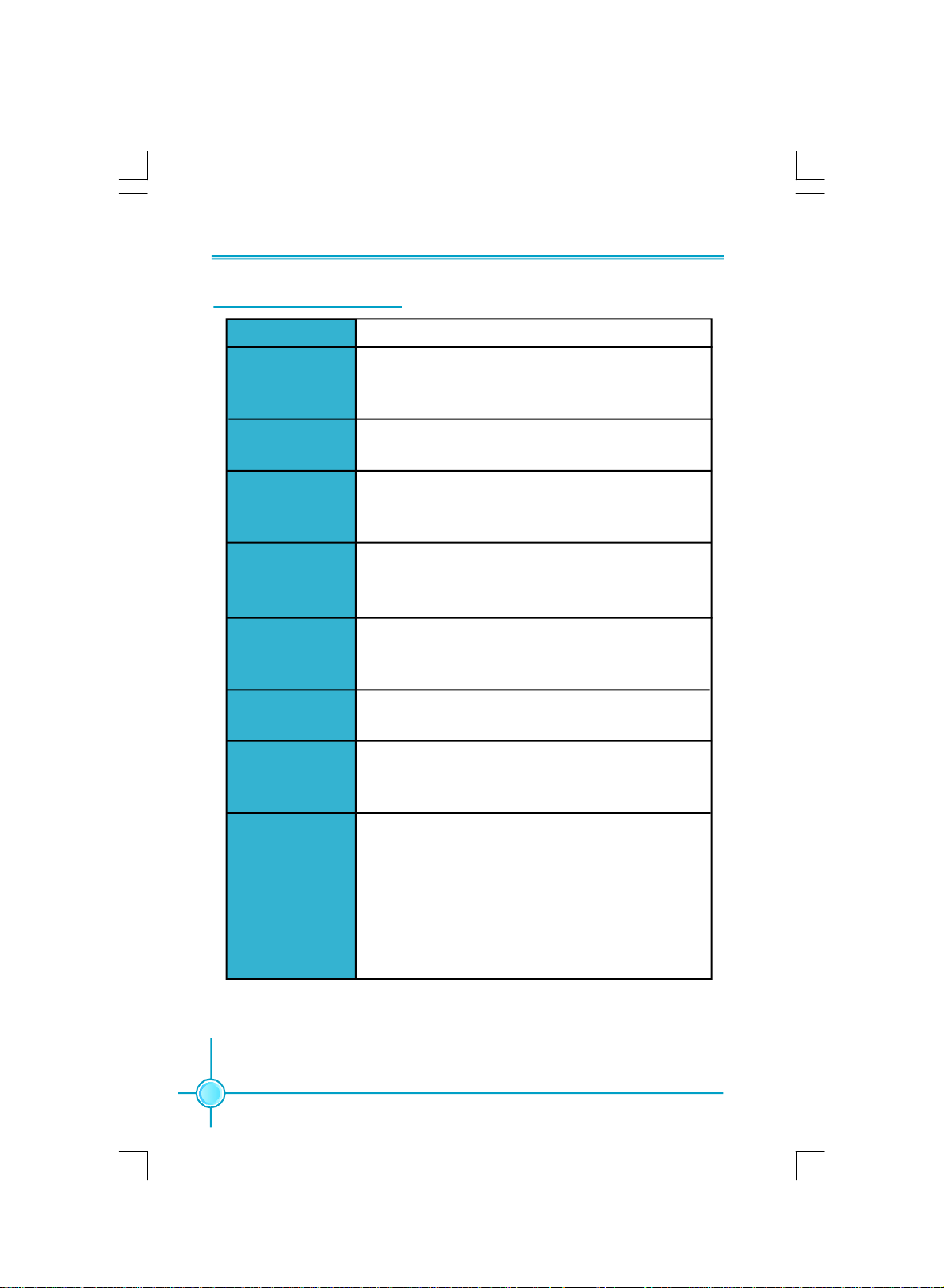
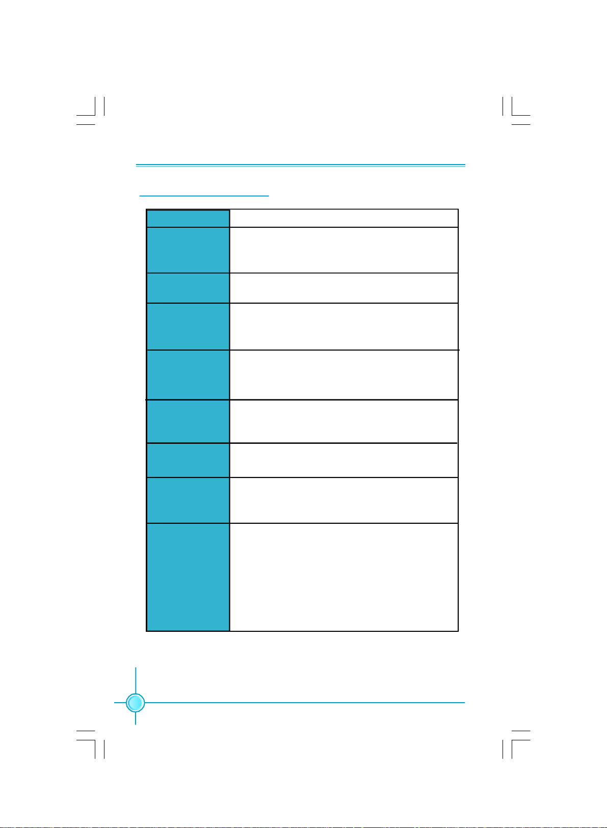
Specifications - - English
Size
CPU
Chipset
Memory
Expansion Slots
Audio
LAN
Storage
·Micro ATX form factor : 244mm x 203mm
· AMD AM2 socket for Athlon
sempronTM Processors
· Supports Hyper Transport
·Northbridge: SIS 761GX
·Southbridge: SIS 968
·2 x 240-pin DIMM slots
·Supports Dual-Channel DDR2 upto 800
·Supports upto 2GB
·1 x PCI Express x16 slot
·1 x PCI Express x1 slot
·2 x PCI slots
·Realtek 6-channel Audio CODEC
·Supports S/PDIF output, Jack-Sensing function,Intel
High Definition Audio
·Realtek 10/100 Mb/s LAN Controller/ Broadcom 10/100
LAN PHY
·2 x Ultra DMA 133/100/66 devices
·2 x SATA 300MB/s devices
·RAID 0, RAID 1 configuration
TM
64x2,AthlonTM 64 and
TM
1.0 Technology
®
Rear Panel I/O
2
·1 x PS/2 Mouse Port
·1 x PS/2 Keyboard Port
·1 x Serial Port(COM1)
·1 x Parallel Port
·1 x VGA Port
·4 x USB 2.0 Ports
·1 x RJ45 LAN Port
·6-channel Audio Ports
(continued on the next page)
Page 8

Chapter 1 Main Features
Internal I/O
Connectors
Support CD
·2 x USB 2.0 headers(supports 4 USB 2.0 ports)
·2 x SATA connectors
·1 x Floppy connector
·1 x IDE connector
·1 x Chassis intruder header(INTR)
·1 x CD_IN header
·1 x Speaker header
·1 x S/PDIF_OUT header(optional)
·1 x COM2 header(optional)
·1 x Front Audio connector
·1 x 24-pin ATX Power Connector
·1 x 4-pin AUX Power Connector
·1 x IrDA header
·1 x CPU Fan connector
·1 x System Fan connector
·1 x NB Fan connector(optional)
·Front panel connector
·Driver
·Utility
·Specifications are subject to change without notice.
3
Page 9

第一章
主要性能
产品规格- -简体中文
尺寸
中央处理器
芯片组
内存
扩展槽
音频
LAN
存储
·mATX 结构: 244mm x 203mm
· 支持Socket AM2 规格 AMD Athlon
64 和 Sempron
· 支持 HyperTransport
TM
处理器
TM
技术
TM
64X2,Athlon
TM
·北桥:SIS 761GX
·南桥:SIS 968
·2个240针脚内存插槽
· 支持双通道DDR2最高可达800
· 内存总容量最大可达2GB
·1 个 PCI Express x16 插槽
·1 个 PCI Express x1 插槽
·2 个 PCI 插槽
·Realtek 6 声道音频编解码器
·支持 S/PDIF 输出,Jack-Sensing 功能, Intel
High Definition Audio
·Realtek 10/100 Mb/s LAN Controller/ Broadcom 10/100
LAN PHY
·2个Ultra DMA 133/100/66设备
·2个SATA 300MB/s设备
·支持 RAID 0,RAID1
®
后面板I/O ·1 个 PS/2 鼠标接口
·1 个 PS/2 键盘接口
·1 个 串行接口(COM1)
·1 个 并行接口
·1 个 VGA 接口
·4 个 USB 2.0 接口
·1 个 RJ45 网络接口
·6声道音频接口
(下页继续)
4
Page 10

第一章
主要性能
内置连接器
实用程序光盘
·规格若有任何更改,恕不另行通知。
·2 个 USB 2.0 接头(提供4个USB 2.0接口)
·2 个 SATA 接头
·1 个 软驱接口
·1 个 IDE 接口
·1 个 机箱开启侦测接头
·1 个 CD_IN 接头
·1 个 Speaker 接头
·1 个 S/PDIF_OUT 接头(选配)
·1 个 COM2接头(选配)
·1 个 前置音频接头
·1 个 24 针ATX 电源接口
·1 个 4 针 ATX_12V 电源接口
·1 个 红外线通讯接头
·1 个 CPU 风扇接头
·1 个 系统风扇接头
·1 个 北桥风扇接头(选配)
·前端面板接头
·驱动程序
·应用程序
5
Page 11
Kapitel 1 Hauptmerkmale
Technische Daten--Deutsch
Größe
CPU
Chipsatz
Speicher
Erweiterungs
steckplätze
Audio
LAN
Speichergeräte
·Micro ATX-Formfaktor: 244mm x 203 mm
· AM2-Sockel für AMD Athlon™ 64 X2, Athlon™ 64 und
Sempron™-Prozessoren
·Unterstützt HyperTransport™-Technologie
·Northbridge: SIS 761GX
·Southbridge: SIS 968
·2 240-polige DIMM-Steckplätze
· Unterstützt Dual-Channel DDR2 bis 800
·Unterstützt bis 2 GB
·1 x PCI Express x16-Steckplatz
·1 x PCI Express x1-Steckplatz
·2 x PCI-Steckplätze
·Realtek 6-Kanal-Audio CODEC
·Unterstützt S/PDIF-Ausgang, Anschlusserkennung, Intel®
High Definition Audio
·Realtek 10/100 Mb/s LAN Controller/ Broadcom 10/100
LAN PHY
· 2 x Ultra DMA 133/100/66-Geräte
· 2 x SATA-Geräte, 300 MB/s
· RAID-Konfiguration 0, 1
I/O-Anschlüsse an
der Rückseite
6
·1 x PS/2-Mausanschluss
·1 x PS/2-Tastaturanschluss
·1 x Seriellanschluss(COM1)
·1 x Parallelanschluss
·1 x VGA-Port
·4 x USB 2.0-Ports
·1 x RJ45-LAN-Port
·6-Kanal-Audio-Ports
(Fortsetzung auf der nächsten Seite)
Page 12

Kapitel 1 Hauptmerkmale
Interne I/OAnschlüsse
Support-CD
·2 x USB 2.0-Anschlussleisten (Unterstützung für 4 USB
2.0-Ports)
·2 x SATA-Anschlüsse
·1 x Diskettenlaufwerkanschluss
·1 x IDE-Anschluss
·1 x Gehäuse-offen-Anschluss (INTR)
·1 x CD_IN-Anschluss
·1 x Lautsprecher-Anschluss
·1 x S/PDIF_OUT-Anschluss(optional)
·1 x COM2-Port-Anschluss(optional)
·1 x Front-Audio-Anschluss
·1 x ATX Power, 24-polig-Anschluss
·1 x AUX Power, 4-polig-Anschluss
·1 x IrDA-Anschluss
·1 x CPU-Lüfter-Anschluss
·1 x Systemlüfter-Anschlüsse
·1 x NB- Lعfter (optional)
·Frontbedienfeld-Anschluss
· Treibe
· Dienstprogramme
·Angaben können sich ohne Vorankündigung ändern.
7
Page 13

Capítulo 1 Principales funciones
Características- - Español
Tamaño
CPU
Conjunto de chips
Memoria
Ranuras
de expansión
Audio
LAN
Almacenamiento
·Micro ATX factor de forma: 244mm x 203mm
· Conector AM2 para procesadores AMD AthlonTM 64 X2,
AthlonTM 64 y SempronTM
· Compatible con HyperTransportTM
·Northbridge: SIS 761GX
·Southbridge: SIS 968
·2 x ranuras DIMM de 240-pin
·Compatible DDR 2 de doble canal con hasta 800
·Compatible con hasta 2GB
·1 x ranura PCI Express x16
·1 x ranura PCI Express x1
·2 x ranuras PCI
·Realtek 6 canales Audio CODEC
·Compatible salida S/PDIF, sensible a conexión, sonido
Intel® de Alta Definición
·Realtek 10/100 Mb/s LAN Controller/ Broadcom 10/100
LAN PHY
· 2 X dispositivos Ultra DMA 133/100/66
· Dispositivo 2 SATA 300MB/s
· Configuración RAID 0, RAID 1
Panel de E/S
trasero
8
·1 x Puerto de ratón PS/2
·1 x Puerto de teclado PS/2
·1 x Puerto Serie(COM1)
·1 x Puerto Paralelo
·1 x Puerto de VGA
·4 x Puertos USB 2.0
·1 x Puerto LAN RJ45
·Puertos 6 canales Audio
(continúa en la página siguiente)
Page 14

Capítulo 1 Principales funciones
Conectores
internos de E/S
CD de soporte
·2 x Cabeceras USB 2.0 (admite 4 puertos USB 2.0)
·2 x Conectores SATA
·1 x Conector de disco flexible
·1 x Conector de IDE
·1 x Cabecera de intrusos en bastidor (INTR)
·1 x Cabecera de CD_IN
·1 x Cabecera de altavoz
·1 x Cabecera S/PDIF_OUT(opcional)
·1 x Conector de puerto COM2(opcional)
·1 x Conector de Audio frontal
·1 x Conector de 24-pin ATX Power
·1 x Conector de 4-pin AUX Power
·1 x Cabecera de IrDA
·1 x Conector de Ventilador de CPU
·1 x Conector de Ventiladores Sistema
·1 x Ventilador NB(opcional)
·Conector de panel frontal
·Controlador
·Utilidades
·Las características se encuentran sujetas a cambios sin aviso previo.
9
Page 15

Capítulo 1 Principais características
Especificações- -Portugués
Tamanho
CPU
Chipset
Memória
Ranhuras de
expansão
Áudio
LAN
Armazenamento
·Factor de forma Micro ATX de 244 x 203 mm
· Socket AM2 para processadores AMD AthlonTM 64 X2,
AthlonTM 64 e SempronTM
· Suporta a tecnologia HyperTransportTM
·Northbridge: SIS 761GX
·Southbridge: SIS 968
·2 ranhuras DIMM de 240 pinos
·Suporta módulos de memória DDR2 até 800 de canal duplo
·Suporta até 2 GB
·1 ranhura PCI Express x16
·1 ranhura PCI Express x1
·2 ranhuras PCI
·Realtek com 6 canais, codec de áudio
·Suporta saída S/PDIF, função Jack-Sensing, áudio de alta
definição da Intel®
·Realtek 10/100 Mb/s LAN Controller/ Broadcom 10/100
LAN PHY
· 2 dispositivos Ultra DMA 133/100/66
· 2 dispositivos SATA de 300 MB/s
· Configuração RAID 0, RAID1
Entrada/Saída
pelo painel
traseiro
10
·1 x Porta para rato PS/2
·1 x Porta para Teclado PS/2
·1 x Porta série (COM1)
·1 x Porta paralela
·1 x Porta VGA
·4 x Portas USB 2.0
·1 x Porta LAN RJ45
·Portas 6 canais, áudio
(continua na página seguinte)
Page 16

Capítulo 1 Principais características
Conectores
internos de
entrada/saída
CD de suporte
·2 x Conectores USB 2.0 (para 4 portas USB 2.0)
·2 x Conectores SATA
·1 x Conector da unidade de disquetes
·1 x Conector IDE
·1 x Conector para detecção de intrusão no chassis(INTR)
·1 x Conector CD_IN
·1 x Conector de altifalante
·1 x Conector S/PDIF_OUT (opcional)
·1 x Conector da porta COM2 (opcional)
·1 x Conector Áudio frontal
·1 x Conector de alimentação ATX de 24 pinos
·1 x Conector de alimentação auxiliar de 4 pinos
·1 x Conector IrDA
·1 x Conector da ventoinha da CPU
·1 x Conector da ventoinha da sistema
·1 x Ventoinha NB(opcional)
·Conector de painel frontal
·Controlador
·Utilitários
·As especificações estão sujeitas a alteração sem aviso prévio.
11
Page 17

Capitolo 1 Caratteristiche principali
Specifiche- -Italiano
Dimensioni
CPU
Chipset
Memoria
Alloggi
d’espansione
Audio
LAN
Archivio
Pannello
posteriore I/O
·Formato micro ATX: 244 mm x 203 mm
· Socket AM2 per processori AMD AthlonTM 64 X2,
AthlonTM 64 e SempronTM
· Supporto tecnologia HyperTransportTM
·Northbridge: SIS 761GX
·Southbridge: SIS 968
·2 alloggi DIMM 240 pin
·Supporto DDR2 fino 800 Dual-Channel
·Supporto fino a 2GB
·1 Alloggio PCI Express x16
·1 Alloggio PCI Express
·2 Alloggi PCI
·Realtek 6-canali audio CODEC
·Supporto output S/PDIF, funzione di rilevamento
connettori, Intel® High Definition Audio
·Realtek 10/100 Mb/s LAN Controller/ Broadcom 10/100
LAN PHY
·2 Dispositivi Ultra DMA 133/100/66
·2 dispositivi SATA 300MB/s
·Configurazione RAID 0, RAID1
·1 x Porta mouse PS/2
·1 x Porta tastiera PS/2
·1 x Porta Seriale (COM1)
·1 x Porta Parallela
·1 x Porta VGA
·4 x Porta USB 2.0
·1 x Porta LAN RJ45
·Porta 6-canali audio
12
(segue alla pagina successiva)
Page 18

Capitolo 1 Caratteristiche principali
Connettori I/O
interni
CD di supporto
·2 x Collettori USB 2.0 (supportano 4 porte USB 2.0)
·2 x Connettori SATA
·1 x Connettore Floppy
·1 x Connettore IDE
·1 x Collettore intrusione telaio (INTR)
·1 x Collettore CD_IN
·1 x Collettore Altoparlante
·1 x Collettore S/PDIF_OUT (optional)
·1 x Collettore porta COM2 (optional)
·1 x Connettore Audio frontale
·1 x Connettore potenza ATX 24 pin
·1 x Connettore potenza AUX 4 pin
·1 x Connettore IrDA
·1 x Connettore ventolina CPU
·1 x Connettore ventolina di sistema
·1 x Ventolina NB (optional)
·Connettore pannello frontale
·Driver
·Utilità
·Le specifiche tecniche sono soggette a cambiamenti senza preavviso.
13
Page 19

Глава 1 Основные характеристики
Технические характеристики- -Русский
·Форм-фактор микро-ATX размером 244 х 203 ммРазмер
Процессор
Набор микросхем
Память
Слоты
расширения
Звук
ЛВС
Устройство
хранения
· Гнездо AM2 для процессоров AMD AthlonTM 64 X2,
AthlonTM 64 и Sempron
· Поддержка технологии HyperTransport
·Северный мост: SIS 761GX
·Южный мост: SIS 968
·2 240-контактных гнезда DIMM
·Поддержка Двухканальная память DDR2 до 800
·Поддержка до 8 Гб
·1 слот PCI Express x16
·1 слот PCI Express x1
·2 слота PCI
·Realtek 6 каналов, звуковой КОДЕК,
·Поддержка Выход S/PDIF, функция определения
разъема, поддержка технологии Intel® High Definition
Audio
TM
TM
·Realtek 10/100 Mb/s LAN Controller/ Broadcom 10/100
LAN PHY
·2 устройств с интерфейсом Ultra DMA 133, 100, 66
·2 устройств с интерфейсом SATA и скоростью
передачи данных 300 Мб/с
·Конфигурации RAID 0,RAID 1
Входы и
выходы на
задней панели
14
·1 Порт мыши PS/2
·1 Порт Клавиатура PS/2
·1 Последовательный порт (COM1)
·1 Параллельный порт
·1 Порт VGA
·4 Порты USB 2.0
·1 Разъем ЛВС RJ45
·Порты 6 каналов, звуковой
(продолжение на следующей странице)
Page 20

Глава 1 Основные характеристики
Встроенные
входы и
выходы
Поддержка
компакт-дисков
·2 Разъемы USB 2.0 (поддержка 4 портов USB 2.0)
·2 Разъемы SATA
·1 Разъем дисковода гибких дисков
·1 Разъем IDE
·1 Разъем датчика открывания корпуса (INTR)
·1 Разъем CD_IN
·1 Разъем Динамик
·1 Разъем выход S/PDIF (дополнительный)
·1 Разъем порт COM2 (дополнительный)
·1 Передний звуковой разъем
·1 Разъем 24-контактный ATX
·1 Разъем 4-контактый AUX
·1 ИК-порт
·1 Разъем Вентилятор процессора
·1 Разъем системный вентилятор
·1 Вентилятор северного моста (дополнительный)
·Передняя панель разъем
·Драйвер
·Служебная программа
·Технические характеристики могут изменяться без уведомления.
15
Page 21

ﻞﺼﻔﻟا1ﺔﯿﺴﯿﺋﺮﻟا ﺺﺋﺎﺼﺨﻟا
تﺎﻔﺻاﻮﻤﻟا
ﺔ ﯿﺑﺮﻌﻟ- -
Ÿ عﻮﻧ ﻦﻣ ﺔﯾوﺎﺣ Micro ATX سﺎﻘﻣ 244 ﻢﻣ× 203ﻢﻣ
ﺔﯾﺰﻛﺮﻤﻟا ﺔﺠﻟﺎﻌﻤﻟا ةﺪﺣو
Ÿ ﺲﺒﻘﻣ AM2 تﺎﺠﻟﺎﻌﻤﻟ AMD AthlonTM 64 X2 و SempronTM and AthlonTM 64
Ÿ ﺔﯿﻨﻘﺗ ﻢﻋدHyperTransportTM
Ÿ ) ﻲﻟﺎﻤﺸﻟا ﺮﺴﺠﻟاNorthbridge:( SIS 761GX
Ÿ ) ﻲﺑﻮﻨﺠﻟا ﺮﺴﺠﻟاSouthbridge:( SIS 968
Ÿ دﺪﻋ2 تﺎﺤﺘﻓDIMM × 240 ﺎﺳﻮﺑد
Ÿ ﻰﻟإ ﻞﺼﯾ ةﺎﻨﻘﻟا ﻲﺋﺎﻨﺛ ﻢﯿﻤﺼﺘﻟا ﻢﻋدDual-Channel DDR2 800
Ÿ ﻰﻟإ ﻞﺼﯾ ﻢﻋد2ﺖﯾﺎﺑ ﺎﺠﯿﺟ
Ÿ دﺪﻋ1 ﺢﺘﻓة PCI Express x16
Ÿ دﺪﻋ1 ﺔﺤﺘﻓPCI Express x1
Ÿ دﺪﻋ2تﺎﺤﺘﻓ PCI
Ÿ ﺔﯿﻨﻘﺘﺑ تاﻮﻨﻗ ﺖﺴﺑ ﻲﺗﻮﺻ ﺰﯿﻣﺮﺗRealtek
Ÿ جﺮﺧ ﻢﻋدS/PDIFﺔﯿﻨﻘﺗ ،ﺲﺒﻘﻤﻟا رﺎﻌﺸﺘﺳا ﺔﻔﯿﻇو ،Intel® High Definition Audio
ﺔﯿﻠﺤﻤﻟا لﺎﺼﺗﻻا ﺔﻜﺒﺷ
Ÿ Broadcom 10/100 LAN PHY/Realtek 10/100 Mb/s LAN Controller
Ÿ دﺪﻋ2 ةﺰﮭﺟأ Ultra DMA 133/ 100/66
Ÿ دﺪﻋ2 ةﺰﮭﺟأSATA 300MB/s
Ÿ ﺔﺌﯿﮭﺗRAID 0, RAID 1
Ÿ دﺪﻋ1 سوﺎﻣ ﺬﻔﻨﻣPS/2
Ÿ دﺪﻋ1 ﺢﯿﺗﺎﻔﻣ ﺔﺣﻮﻟ ﺬﻔﻨﻣPS/2
Ÿ دﺪﻋ1 ﻲﻠﺴﻠﺴﺗ ﺬﻔﻨﻣ(COM1)
Ÿ دﺪﻋ1 يزاﻮﺘﻣ ﺬﻔﻨﻣ
Ÿ دﺪﻋ1 VGA ﺬﻔﻨﻣ
Ÿ دﺪﻋ4 ﺬﻓﺎﻨﻣUSB 2.0
Ÿ دﺪﻋ1 ﺔﯿﻠﺤﻣ لﺎﺼﺗا ﺔﻜﺒﺷ ﺬﻔﻨﻣRJ45
Ÿ ﺬﻓﺎﻨﻣ ﻲﺗﻮﺻ 6ﺔﯿﻨﻘﺘﺑ تاﻮﻨﻗ
ﻢﺠﺤﻟا
ﻖﺋﺎﻗﺮﻟا
ةﺮﻛاﺬﻟا
ﺔﻌﺳﻮﺘﻟا تﺎﺤﺘﻓ
تﻮﺼﻟا
ﻦﯾﺰﺨﺘﻟا
ﺬﻓﺎﻨﻣ ﺔﺣﻮﻠﻟ جﺮﺨﻟا/ﻞﺧﺪﻟا
ﺔﯿﻔﻠﺨﻟا
ﺔﯿﻟﺎﺘﻟا ﺔﺤﻔﺼﻟا ﻊﺑﺎﺗ
16
Page 22

جﺮﺨﻟا / ﻞﺧﺪﻟا ﻞﯿﺻﻮﺗ ﺬﻓﺎﻨﻣ
مﺪﻤﻟا صﺮﻘﻟا ﻢﻋد
Ÿ دﺪﻋ2 فاﺮﻃأ ﻞﯿﺻﻮﺗ USB 2.0) ﻢﻋﺪﺗ4 ﺬﻓﺎﻨﻣ USB 2.0(
Ÿ دﺪﻋ2 ﻞﯿﺻﻮﺗ ﺬﻓﺎﻨﻣ SATA
Ÿ دﺪﻋ1ﺔﻧﺮﻤﻟا صاﺮﻗﻷا كﺮﺤﻣ ﻞﯿﺻﻮﺗ ﺬﻔﻨﻣ
Ÿ دﺪﻋ1 ﻞﯿﺻﻮﺗ ﺬﻔﻨﻣ IDE
Ÿ دﺪﻋ1ﻞﯿﺻﻮﺗ فﺮﻃ Intruder ﻞﻜﯿﮭﻠﻟ )(INTR
Ÿ دﺪﻋ1ﻞﯿﺻﻮﺗ فﺮﻃ CD_IN
Ÿ دﺪﻋ1ﺔﻋﺎﻤﺴﻟا ﻞﯿﺻﻮﺗ فﺮﻃ
Ÿ دﺪﻋ1 ﻞﯿﺻﻮﺗ فﺮﻃ S/PDIF _ OUT) يرﺎﯿﺘﺧا(
Ÿ دﺪﻋ1ﻞﯿﺻﻮﺗ ﺬﻔﻨﻣ COM2 )يرﺎﯿﺘﺧا(
Ÿ ﻲﻣﺎﻣﻷا تﻮﺼﻟا ﻞﺻﻮﻣ
Ÿ دﺪﻋ1 ﺔﻗﺎﻃ ﻞﺻﻮﻣ ATX ء، 24 سﻮﺑد
Ÿ دﺪﻋ1 ﺔﻗﺎﻃ ﻞﺻﻮﻣ AUX × 4 ﺲﯿﺑﺎﺑد
Ÿ دﺪﻋ 1 ﻞﯿﺻﻮﺗ فﺮﻃ IrDA
Ÿ دﺪﻋ1 ﺔﯾﺰﻛﺮﻤﻟا ﺔﺠﻟﺎﻌﻤﻟا ةﺪﺣﻮﻟ ﺔﺣوﺮﻣ
Ÿ دﺪﻋ1مﺎﻈﻨﻟا ﺔﺣوﺮﻤﻟ ﻞﺻﻮﻣ
Ÿ دﺪﻋ1 ﺔﺣوﺮﻣ NB )يرﺎﯿﺘﺧا (
Ÿ ﺔﯿﻣﺎﻣﻷا ﺔﺣﻮﻠﻟا ﻞﺻﻮﻣ
Ÿ ﻞﯿﻐﺸﺘﻟا ﺞﻣﺎﻧﺮﺑ
Ÿ تاودﻷا
ﻞﺼﻔﻟا1ﺔﯿﺴﯿﺋﺮﻟا ﺺﺋﺎﺼﺨﻟا
ﺔﯿﻠﺧاﺪﻟا
Ÿ .ﻖﺒﺴﻣ رﺎﻄﺧإ نوﺪﺑ تﺎﻔﺻاﻮﻤﻟا ﺮﯿﻐﺘﺗ ﺪﻗ
17
Page 23

Chapter 1 Main Features
Jumpers
This section explains how to setup jumpers. You should read the following
content carefully prior to modifying any jumper settings.
Attention
The jumpers on the motherboard, pin 1 can be identified by the
bold silkscreen next to it. And in this manual, pin 1 is simply labeled as “ 1”.
Clear CMOS Jumper: CLR_CMOS
The CLR_CMOS jumper allows you to clear the data in CMOS. The data
includes system setup information such as system password, data, time,
and system setup parameters. To clear and reset the system parameters to
default setup, please do as follows:
1. Turn off the computer and unplug the power cord
from the power supply.
2. Move the jumper cap from pins 2-3 (default) to pins
1-2. Keep the cap on pins 1-2 for several seconds,
then move the cap back to pins 2-3.
3. Plug the power cord and turn on the computer.
CLR_ CMOS
Normal
(default)
Clear
1
1
USB device wake-up Jumper: FUSBPWR/RUSBPWR
1.Set the jumper to pins 1-2 (+5V) to wake up the
computer from S1 sleep mode using the connected
USB devices.
+5VSB
2.Set the jumper to pins 2-3 (+5VSB) to wake up the
computer from S3 and S4 sleep modes using the
connected USB devices.At the same time, a corres-
+5V
(Default)
ponding setting must be set in BIOS as below:
Set “CMOS Setup”=>“Power Management Setup”=>
“PM Wake Up Events”=>“USB Port Wake Up Control”
FUSBPWR / RUSBPWR
to “Enabled”.
Note
1. FUSBPWR is for the internal USB connectors, RUSBPWR is for the
rear USB ports.
2. The USB device wake-up feature requires a power supply that can
provide 500mA on +5VSB lead for each USB port; otherwise, the system
will not power up.
3. The total current consumed must not exceed the power supply capability (+5VSB) whether under normal condition or in sleep mode.
18
1
1
Page 24

Chapter 1 Main Features
Keyboard Jumper: KBPWR
This jumper allows you to enable or disable the Keyboard
wake-up feature. To use it, firstly you need set “Power
Management Setup”=>“PM wake up Events”=>“Power On
By Keyboard ” to “Any KEY” or “Hot KEY” in the COMS Setup.
Secondly please set the jumper to pins 2-3(+5VSB) .Now
you are able to wake up the computer from S3 , S4 and S5
sleep modes by pressing any key or the hot key on the
keyboard. If you set “Power On By Keyboard ” to “Password”,
Please set the password by entering “KB Power On Pass-
word ”. If you set “Power On By Keyboard ” to “Keyboard 98”,
you can wake up your computer from sleep modes by
pressing the “Power” key on keyboard 98.
+5V
(Default)
+5VSB
KBPWR
1
1
19
Page 25

Chapter 2 BIOS Description
Chapter
This chapter tells how to change system settings through the
BIOS Setup menus. Detailed descriptions of the BIOS parameters are also provided.
You have to run the Setup Program when the following cases
occur:
1.An error message appears on the screen during the system
POST process.
2.You want to change the default CMOS settings.
This chapter includes the following information:
v Advanced Chipset Features
2
v Enter BIOS Setup
v Main Menu
v Standard CMOS Features
v Fox Central Control Unit
v Advanced BIOS Features
v Integrated Peripherals
v Power Management Setup
v PnP/PCI Configuration
v PC Health Status
v Load Fail-Safe Defaults
v Load Optimized Defaults
v Set Supervisor Password
v Save & Exit Setup
v Exit Without Saving
20
Page 26

Chapter 2 BIOS Description
Enter BIOS Setup
The BIOS is the communication bridge between hardware and software,
correctly setting up the BIOS parameters is critical to maintain optimal system
performance. Power on the computer, when the following message briefly
appears at the bottom of the screen during the POST (Power On Self Test),
press <Del> key to enter the BIOS CMOS Setup Utility.
Press TAB to show POST Screen, DEL to enter SETUP, ESC to enter Boot Menu.
Note:
We do not suggest that you change the default parameters in the BIOS Setup,
and we shall not be responsible for any damage that result from any changes
that you make.
Main Menu
The main menu displays a list of options that are available. Use the arrow keys
to select among the items, when the correlative information of the the items will
appear at the bottom, and execute the sub-menu by pressing <Enter>.
Main Menu
The items in the main menu are explained as below:
1. Standard CMOS Features
The basic system configuration can be set up through this menu.
2. Fox Central Control Unit
The special features can be set up by this menu.
3. Advanced BIOS Features
The advanced system features can be set up through this menu.
4. Advanced Chipset Features
The advanced chipset features can be set up through this menu.
5. Integrated Peripherals
All onboard peripherals can be set up through this menu.
6. Power Management setup
Through this menu you can set up all the items of Green function features.
21
Page 27

Chapter 2 BIOS Description
7. PnP/PCI Configuration
The system’s PnP/PCI settings and parameters can be modified by
this menu.
8. PC Health Status
This menu will display the current status of your PC.
9. Load Fail-Safe Defaults
You can load the Failsafe default BIOS settings through this menu.
10. Load Optimized Defaults
You can load the optimal performance settings by this menu, however,the
stable default values may be affected.
11. Set Supervisor Password
Set User Password
You can set Supervisor/ User password by this menu.
12. Save & Exit Setup
Save CMOS value settings to CMOS and exit setup.
13. Exit Without Saving
Abandon all CMOS value changes and exit setup.
Below describes the function of each sub-menu in detail for you.
1.Standard CMOS Features
This sub-menu is used to set up the standard BIOS parameters, such as the
date, time, floppy driver and so on. Select the item by the arrow keys, and then
use the <+> or <-> keys to choose the setting values.
Standard CMOS Features
1.1 Date(mm:dd:yy)
This option allows you to set the desired date (usually as the current day) with
the <day><month><date><year> format.
Day—weekday from Sun. to Sat., defined by BIOS (read-only).
Month—month from Jan. to Dec..
Date—date from 1st to 31st, can be changed using the keyboard.
Year—year, set up by users.
22
Page 28

Chapter 2 BIOS Description
1.2 Time(hh:mm:ss)
This option allows you to set up the desired time (usually as the current time)
with <hour><minute><second> format.
1.3 IDE Channel 0 Master/Slave,IDE channel 2/3 Master
These categories identify the HDD types of 3 IDE channels installed in the computer
system. There are three choices provided for the Enhanced IDE BIOS: None, Auto, and
Manual. “None” means no HDD is installed or set; “Auto” means the system can auto-
detect the hard disk when booting up; by choosing “Manual” and changing Access
Mode to “CHS”, the related information should be entered manually. Enter the informa
tion directly from the keyboard and press < Enter>:
Cylinder number of cylinders Head number of heads
Precomp write pre-compensation Landing Zone landing zone
Sector number of sectors
Award (Phoenix) BIOS can support 3 HDD modes: CHS, LBA and Large or Auto mode.
CHS For HDD<528MB
LBA For HDD>528MB & supporting LBA (Logical Block Addressing)
Large For HDD>528MB but not supporting LBA
Auto Recommended mode
1.4 Drive A
This option allows you to select the kind of FDD to be installed,including“None”,
[360K, 5.25 in], [1.2M, 5.25 in], [720K, 3.5 in], [1.44M, 3.5 in] and [2.88 M, 3.5 in].
1.5 Halt On
This category determines whether or not the computer will stop if an error is
detected during powering up.
All Errors Whenever the BIOS detects a nonfatal error, the system
will stop and you will be prompted.
No Errors The system boot will not stop for any errors that may
be detected.
All, But Keyboard The system boot will not stop for a keyboard error; but
it will stop for all other errors.
All, But Diskette The system boot will not stop for a diskette error; but
it will stop for all other errors.
All, But Disk/Key The system boot will not stop for a keyboard or disk error,
but it will stop for all other errors
1.6 Installed Memory
This item is used to show the installed memory of the system.
23
Page 29

Chapter 2 BIOS Description
2.Fox Central Control Unit
Fox central control Unit
2.1 [SuperBIOS-Protect]
SuperBIOS-Protect
Super-BIOS Protect Function protects PC from viruses,e.g. CIH, by using a
HW/SW double BIOS lock technology.
2.2 [SuperSpeed]
Auto Detect PCI CIK
This option is used to set whether the clock of an unused PCI slot will be
disabled to reduce electromagnetic interference. The setting values are
Disabled and Enabled.
2.3 Spread Spectrum
This item is used to set the spread spectrum functions.
NOTE: The Spread Spectrum function can influence the EMI degree.
2.4 CPU Clock
This item is used to set CPU clock.
3. Advanced BIOS Features
3.1 CPU feature
Press enter to set the items of CPU feature.
3.2 Removable Device Priority
This option is used to specify the Boot Device priority sequence from
24
Advanced BIOS Features
Page 30

Chapter 2 BIOS Description
available removable drives.
3.3 Hard Disk Boot Priority
This option is used to select the priority for HDD startup. After pressing
<Enter>, you can select the HDD using the <PageUp>/<PageDn> or Up/
Down arrow keys, and change the HDD priority using <+> or <->; you can
exit this menu by pressing <Esc>.
3.4 CPU Internal cache
This option is used to enable or disable the CPU Internal cache.
3.5 First/Second/Third Boot Device
This option allows you to set the boot device’s sequence.
3.6 Boot Other Device
With this function set to enable, the system will boot from some other de-
vices if the first/second/third boot devices failed. The setting values are: Dis-
abled and Enabled.
3.7 Boot Up Numlock Status
This item defines if the keyboard Num Lock key is active when your system is
started. The available setting values are: On and Off.
3.8 Security Option
When it is set to “Setup”, a password is required to enter the CMOS Setup
screen; When it is set to “System”, a password is required not only to enter
CMOS Setup, but also to start up your PC.
3.9 MPS Version Control For OS
This option is used to set up the version of MPS Table used in OS.
3.10 OS Select For DRAM > 64MB
This option is only required if you have installed more than 64 MB of memory
and you are running the OS/2 operating system.Otherwise,leave this item at
the default.
3.11 HDD S.M.A.R.T Capability
S.M.A.R.T (Self Monitoring Analysis and Reporting Technology) is a technology
that enables a PC to in some cases predict the future failure of storage devices
(like hard disk drives). The default value is Disabled.For making use of the S.M.
A.R.T. feature you would require a software (or BIOS) that enables and moni tors the S.M.A.R.T status of your hard drive, and an operating system that
supports the S.M.A.R.T feature i.e. Windows 95 or higher. Some BIOS contain
this software, otherwise EZ-SMART from StorageSoft is an example of a utility
that can enable and monitor the SMART status of your drive too (only available
for Windows 98 and Windows NT).
25
Page 31

Chapter 2 BIOS Description
3.12 Delay For HDD [Secs]
This item is used to support some old models or special types of hard disks
or CD-ROMs.They may need a longer amount of time to initialize and prepare
for activation. Since the BIOS may not detect those kinds of devices during
system booting.You can adjust the value to fit such devices. Larger values will
give more delay time to the device. The minimum number you can enter is 0,
and the maximum number you can enter is 15.The default setting is 3.
3.13 Full Screen Show
This item is used to set whether to show the logo in full screen or not when
start system.
3.14 Small Logo [EPA] Show
This item is used to set whether to show the EPA logo or not when start system.
4. Advanced Chipset Features
Advanced Chipset Features
4.1 DRAM Configuration
Press “ Enter” to set parameters of DRAM ,such as memory clock frequency
and so on. You ‘d better keep the default values unchanged.
4.2 Hypertransport Control
This item is used to control Hypertransport.Press “Enter” key,you are able to
set the Hypertransport width and speed.
4.3 OnChip VGA Control
This item is used to control OnChip VGA.Press “Enter” key ,you are able to set
the VGA Shared Memory size,Graphics Engin frequency and the GUI Memory
Clock frequency.
26
Page 32

Chapter 2 BIOS Description
5. Integrated Peripherals
Integrated Peripherals
5.1 SIS OnChip IDE Device
Press Enter to set the parameters of the SIS OnChip IDE Device.
5.2 SIS OnChip PCI Device
Press Enter to set the parameters of the SIS OnChip PCI Device.
5.3 Onboard SuperIO Device
Press Enter to set the parameters of the Onboard SuperIO Device.
5.4 IDECH0/1/2/3 Access Interface
The default setting is EDB Bus.The EDB Bus is SIS special degisned bus
to enhance access performance.
5.5 USB2.0 Access Interface
The default setting is EDB Bus.The EDB Bus is SIS special degisned bus
to enhance access performance.
6. Power Management Setup
Power Management Serup
6.1 ACPI Function
ACPI stands for “Advanced Configuration and Power Interface”. ACPI is
a standard that defines power and configuration management interfaces
between an operating system and the BIOS. In other words, it is a
standard that describes how computer components work together to
27
Page 33

Chapter 2 BIOS Description
manage system hardware. In order to use this function the ACPI specification
must be suported by the OS (for example, Windows2000 or WindowsXP). The
available setting values are: Enabled and Disabled.
6.2 ACPI Suspend Type
ACPI stands for “Advanced Configuration and Power Interface”. ACPI is a
standard that defines power and configuration management interfaces between an operating system and the BIOS. In other words, it is a standard
that describes how computer components work together to manage
system hardware. In order to use this function the ACPI specification must
be sup ported by the OS (for example, Windows2000 or WindowsXP). The
available setting values are: Enabled and Disabled.
6.3 Switch Function
This item is used to enable or disable switch function to wake up.
6.4 Power Button Override
This item is used to set the power down method. This function is only valid
for systems using an ATX power supply.When “Instant Off” is selected, press
the power switch to immediately turn off power. When “Delay 4 Sec” is selected,
press and hold the power button for four seconds to turn off power.
6.5 Power State Resume Control
This item is used to control power resume state.
6.6 PM Wake Up Events
Press Enter to set the parameters of Power Management Wake Up Events.
6.7 HPET Support
This item is used to enable or disable HPET.
6.8 HPET Mode
This item is used to select HPET Mode.
7.PnP/PCI Configuration
7.1 Init Display First
This option is used to set which display device will be used first when start up PC .
28
PnP/PCI Configuration
Page 34

Chapter 2 BIOS Description
7.2 Resource controlled By
This option is used to define the system resource control scheme. If
allcards you use support PnP, then select Auto (ESCD) and the BIOS automatically distributes interruption resources. If you install ISA cards not
supporting PnP, you will need to select “Manual” and manually adjust
interruption resources in the event of hardware conflicts. However, since this
motherboard has no ISA slot, this option does not apply.
7.3 IRQ Resources
If you set “Resources Controlled By” for “Manual”, you can modify the item.
Press the <Enter> key, then manually set IRQ resources.
7.4 PCI /VGA Palette Snoop
If you use a non-standard VGA card, use this option to solve graphic accel
eration card or MPEG audio card problems (e.g., colors not accurately
displayed).
7.5 **PCI Express relative items**
Maximum ASPM susported
Control maximum level of ASPM supported on the given PCI Express links
on the system.
7.6 Maximum Payload Size
This option is used to maximum TLP payload size for PCI Express devices.
The unit is byte.
8. PC Health Status
PC Health Status
8.1 Case Open Warning
This option is used to enable or disable case open warning function.
8.2 Shutdown Temperature
This item is used to set upper limitation of system temperature.When the
temperature is higher than the setting values, the motherboard will automatically cut off the power of computer.
8.3 CPU Vcore/+1.8V/+3.3V/+5V/+12V
The current voltages will be automatically detected by the system.
29
Page 35

Chapter 2 BIOS Description
8.4 CPU/System Temperature
The CPU/System temperature will be automatically detected by the system.
8.5 CPU Fan Speed/System Fan Speed/NB FAN Speed
The CPU/system/NB fan speed will be automatically detected by the system.
8.6 Smart Fan Control
This item is used to enable or disable smart fan function.
8.7 PWM Start Temp[ 0C]
This item is used to set beginning temperature. when temperature gets to
this value, Smart Fan starts to take effect.
8.8 Start PWM Value[0~127]
This item is used to set the beginning rotated speed for Smart Fan.
8.9 slope PWM Value
This item is used to set the rotated speed level which Smart Fan varies with
variational temperature. When temperature increase one degree, rotated speed
raises the set level.
8.10 Delta Temp[ 0C]
when "Smart Fan Control" is Enabled.This option can key in from 0 to 31.
9. Load Fail-safe Defaults
This menu allows you to load defaults set by BIOS ,which have set the basic
functions of system in order to ensure the stability of system.You can select
<Y> or <N> and then press <Enter> to load or not load defaults.
10. Load Optimized Defaults
This menu can let you load the optimized defaults set by BIOS, which have set
the optimized performance parameters of system to improve the performances
of system components.You can select <Y> or <N> and then press <Enter> to
load or not load the optimized defaults.
11. Set Supervisor Password
Set User Password
The access rights and permissions associated with the Supervisor password
are higher than those of a regular User password. The Supervisor password
can be used to start the system or modify the CMOS settings. The User pass
word can also start the system. While the User password can be used to view
the current CMOS settings, these settings cannot be modified using the
User password.When you select the Set Supervisor/User Password option, the
following message will appear in the center of the screen, which will help you to
set the password:
Enter Password:
30
Page 36

Chapter 2 BIOS Description
Enter your password, not exceeding 8 characters, then press <Enter>. The
password you entered will replace any previous password. When prompted,
key in the new password and press <Enter>.
If you do not want to set a password, just press <Enter> when prompted to enter
a password, and the following message will appear on the screen. If no pass
word is keyed in, any user can enter the system and view/modify the CMOS
settings.
PASSWORD DISABLED!!!
Press any key to continue …
Under the menu “Advanced BIOS Features Setup”, if you select “System” from
the Security Option, you will be prompted to enter a password once the system
is started or whenever you want to enter the CMOS setting program. If the incorrect password is typed, you will not be permitted to continue.
Under the menu “Advanced BIOS Features Setup”, if you select “Setup” from the
Security Option, you will be prompted to enter a password only when you enter
the CMOS setting program.
12. Save & Exit Setup
When you select this option and press <Enter>, the following message will
appear in the center of the screen:
SAVE to CMOS and EXIT (Y/N)?Y
Press <Y> to save your changes in CMOS and exit the program; press <N> or
<ESC> to return to the main menu.
13. Exit Without Saving
If you select this option and press <Enter>, the following message will appear
in the center of the screen:
Quit Without Saving (Y/N)?Y
Press <Y> to exit CMOS without saving your modifications; press <N> or
<ESC> to return to the main menu.
31
Page 37

Chapter 4 Driver CD Introduction
Chapter
This chapter will introduce how to use attached software.
This chapter provides the following information:
3
3
v FOX ONE
v FOX LiveUpdate
v FOX LOGO
v FOX DMI
32
Page 38

Chapter 3 Directions for Bundled Software
FOX ONE
FOX ONE is a powerful utility for easily modifying system settings. It also allows
users to monitor various temperature values, voltage values, frequency and fan
speed at any time.
With FOX ONE, you can modify system performance settings such as bus speed,
CPU voltage, fan speed, and other system performance options that are supported
by the BIOS and you also can monitor hardware temperature, voltage, frequency
and fan speed.
Supported Operating Systems:
-Windows 2000 -Windows XP (32-bit and 64-bit)
-Windows 2003 (32-bit and 64-bit) -Windows Vista (32-bit and 64-bit)
Using FOX ONE:
1. Main Page
Show CPU Information
Use the toolbar to navigate to
other pages
Alert Lamp
Switch Button
Skin Button
Exit
Minimum
Configuration
Homepage
Alert Lamp
When the system is in healthy status, the alert lamp color is green. And if the system
is in abnormal status, the alert lamp color will turn red.
Switch Button
Click this button, it will simplify the interface to HW monitor information bar as the
below figure shows. The bar could help you to monitor if your system is in the
healthy status at any time.
Monitor Frequency/Voltage/Fan speed/Temperature value
33
Page 39

Chapter 3 Directions for Bundled Software
Click here to return to
previous status
Skin Button
Click this button, you will see the additive figures such as “crystal”and “rock”. Please
select your favorite skin.
Exit
Click this button to exit the program.
Minimum
Click this button to minimize the window.
Configuration
This function is used to configurate the parameters for the program. It deter-
mines which items will be shown in simple mode.Besides,it also provides F.I.S
calibration function which will re-calibrate the CPU’s loading. F.I.S calibration
function is optional.
Homepage
Click this button to visit FOXCONN motherboard website.
2. CPU Page - CPU Control
This page is used to select and run the CPU frequency to determine the current
performance level of the system. You can adjust manually or select “Auto
Overclock”. Otherwise, it also provides FOX Intelligent Stepping,But this function
is optional.
Go to CPU page
34
Reset the
changes
Select the different
benchmarks
Close this page
Auto
Overclocking
Ajust by manual
Apply the
changes
Page 40

Chapter 3 Directions for Bundled Software
3. Freq. Page - Frequency Control
In this page ,you can set memory and PCI Express frequency manually.
Go to Freq. page
Close this page
Select the option
you want to set
Adjust manually
Reset the changes
Apply the changes
4. Limit Setting - Adjust page
This page includes five different sections. “CPU Temp.” and “Sys Temp.” will help
you to set high limit temperature. “CPU Fan”, “Sys. Fan” and“FAN1 fan” are used
to set low limit rpm. And all of them have alert function.
Go to Limit Setting page
Set high limit by dragging the lever
Show current CPU temperature value
Enable alert function
when the CPU
temperature is higher
than high limit value
Show current high
limit value of CPU
temperature
5. Voltage Page - Voltage Control
This page allows you to set CPU, memory and North Bridge voltage manually.
35
Page 41

Chapter 3 Directions for Bundled Software
Go to Voltage page
Select the option
you want to set
Adjust manually
Reset the changes
Apply the changes
6. Fan Page - Fan Control
This page allows you to enable Smart Fan function and set fan speed manually.
Go to Fan page
Enable or disable
smart fan function
Set fan speed by
dragging the lever
Apply the changesReset the changes
FOX LiveUpdate
FOX LiveUpdate is a useful utility to backup and update the system BIOS online
or locally.Drivers and utilities are aslo can be updated online.
Supported Operating Systems:
-Windows 2000 -Windows XP (32-bit and 64-bit)
-Windows 2003 (32-bit and 64-bit) -Windows Vista (32-bit and 64-bit)
36
Page 42

Chapter 3 Directions for Bundled Software
Using FOX LiveUpdate:
1. Local Update
“BIOS Info” tells you the system BIOS information; “Backup BIOS” could
backup your system BIOS ,please click this button ,then key in a BIOS name
and save it ; “Update BIOS” helps to update your system BIOS from local BIOS
files ,please follow the wizard to finish the operation.
Exit
Link to website
Minimum
Toolbar
Show current
BIOS information
2. Online Update
This area lets you update your system BIOS,Drivers,Utilities and all of them from
Internet. Click “start”, it will search the new BIOS ,Drivers and Utilities from Internet.
Then follow the wizard to finish the update operation.
Current
Click here
information
Search new BIOS,
Drivers and
Utilities from Internet
3. Configure
“Option” provides auto search options and version filter. After setting the auto search
options, the utility will work in the background and the related information will show in
a pop balloon notification;
37
Page 43

Chapter 3 Directions for Bundled Software
Click the “System” button,you can set the backup BIOS location and change different
skin of the utility;“Advance”helps you to flash BIOS,Boot Block and clear CMOS ,we
recommend that you keep the default setting unchanged to avoid damagement.
Set auto
search options
Click here
Apply the
changes
Select search
which kind of
versions
Reset to default
value
4. About & Help
This page shows some information about FOX LiveUpdate.
Show information
Click here
about FOX
LiveUpdate
FOX LOGO
FOX LOGO is a simple and useful utility to backup, change and delete the boot
Logo. The boot Logo is the image that appears on screen during the Power-On
Self-Tests (POST).
Supported Operating Systems:
-Windows 2000 -Windows XP (32-bit and 64-bit)
-Windows 2003 (32-bit and 64-bit) -Windows Vista (32-bit and 64-bit)
Using FOX LOGO:
38
Page 44

Main Page
Chapter 3 Directions for Bundled Software
Main screen
Backup
Change
Delete
Exit
Minimize
Website
About
Warning:
When you change Logo or delete the current Logo, the system will flash
BIOS file automatically.During this time, please DO NOT shut down the
application and the system, or the motherboard will be damaged seriously.
FOX DMI
FOX DMI is a full DMI information viewer,and it supports three kinds of DMI Data
format :Report , Data Fields and memory Dump.
Supported Operating Systems:
-Windows 2000 -Windows XP (32-bit and 64-bit)
-Windows 2003 (32-bit and 64-bit) -Windows Vista (32-bit and 64-bit)
Using FOX DMI:
Please operate this utility as the comments shows .
Click here to select
the type you want
to view.
Click here to select
the DMI Data format
you need
39
 Loading...