

Foxcon Terrier T200 LSA Flight Manual
Terrier T200 LSA Flight Manual Rev No.: 1.0 15 April 2008 Page 1 of 31
FOXCON
Aviation & Research Pty Ltd
291 Gormley’s Road Seaforth Mackay QLD 4741
Ph/Fax: 07 4959 0252 Mobile: 0418 747 751
www.Foxcon.com
Aviation@Foxcon.com
Flight Manual
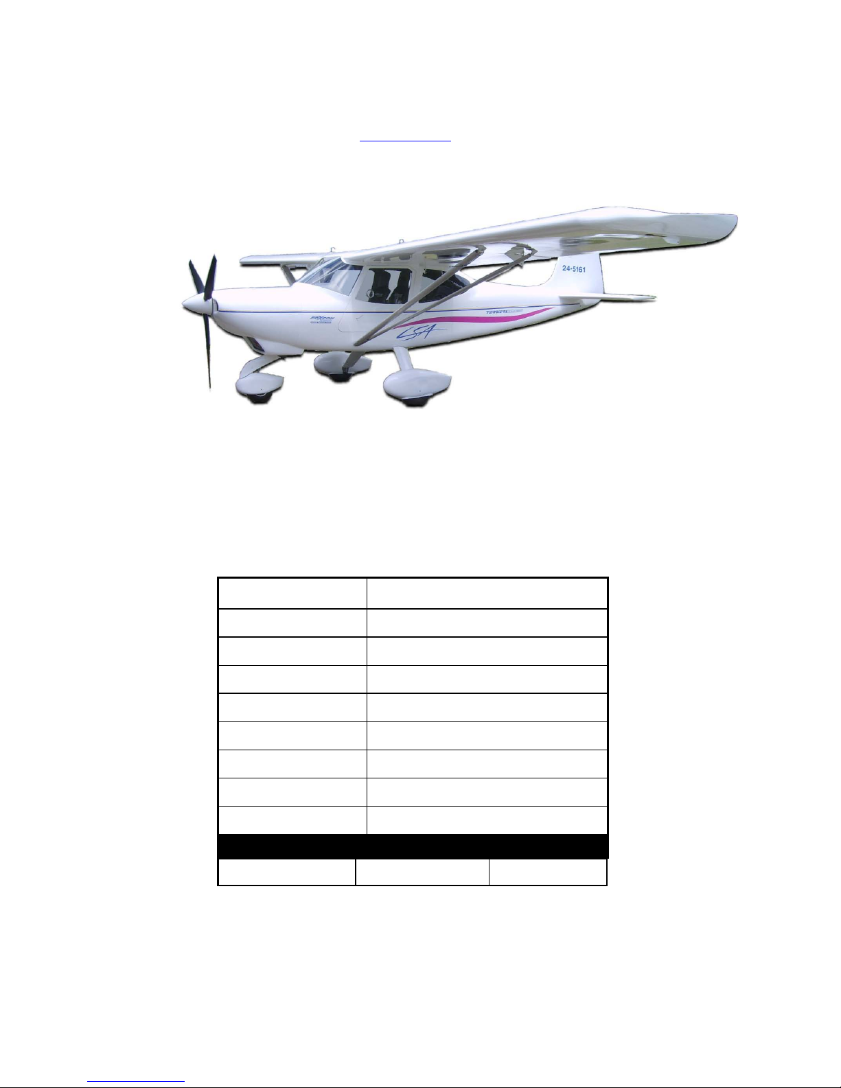
Terrier T200 LSA
Aircraft Registration
Number:
21-5161
Aircraft Serial Number:
#040701
Power plant:
Subaru EA-81
Power plant Serial No:
544848
Propeller:
Bolly BOS3
Date of First Flight:
05.03.08
Current Owner:
Address:
Empty Weight Moment Date Weighed
323kg
698.26
25.02.08
NOTE: Please keep all the above information current, and notify Foxcon Aviation &
Research Pty Ltd of any changes in ownership, address, or aircraft equipment and/or
modifications.
You are reminded that as part of the LSA certification, any modifications to the aircraft,
including any change in the instrument or engine package supplied from the factory,
has to be approved by Foxcon Aviation & Research Pty Ltd.

Terrier T200 LSA Flight Manual Rev No.: 1.0 15 April 2008 Page 2 of 31
Table of Contents
1.0 Introduction
2.0 Overall Dimensions
3.0 Specifications
4.0 Limitations
5.0 Normal Operations
6.0 Checklist & Procedures
7.0 Emergency Procedures
8.0 Operational Checklists
9.0 Other Procedures
10.0 Performance
11.0 Definitions
Speeds
Meteorological Terminology
Engine Power Terminology
Airplane Performance and Flight Planning Terminology
Weight and Balance Terminology
12.0 Abbreviations
13.0 Revision History
14.0 List of Valid Pages
15.0 Appendix
Weight & Balance

Terrier T200 LSA Flight Manual Rev No.: 1.0 15 April 2008 Page 3 of 31
1.0 Introduction
This is an Advanced Ultralight Aeroplane of composite construction.
The Foxcon LSA TERRIER T200 aircraft is a factory built aircraft. Each aircraft is subjected to factory flight test
program to determine that particular aircraft’s performance and characteristics complies with the design
standard.
The purpose of this manual is to provide guidance to owners and mechanics who wish to operate, undertake
maintenance, repairs, and alterations on the Terrier T200 LSA. If in any doubt, please contact the
manufacturer.
This Flight Manual applies only to the particular aircraft identified by the registration marking and serial number
on the Cover Page and contains the airworthiness limitations and essential operating data for this aircraft.
The Flight Manual shall be carried in the aircraft on all flights.
The pilot in command of the aircraft shall comply with all requirements, procedures and limitations with respect
to the operation of the aircraft set out in the Flight Manual for the aircraft.
Amendments shall be issued by Foxcon Aviation & Research Pty Ltd as necessary and will take the form of
replacement pages with the amendment date at the bottom of the page.
Interim / temporary amendments may be issued in the same manner and are to be inserted as directed. These
amendments will be issued on coloured pages and will take precedence over the stated affected page. It is the
owner’s responsibility to incorporate in this manual all such amendments, and to enter the date of incorporation
and his signature on the appropriate Amendment Record Sheet.
No entries or endorsements may be made to this Flight Manual except in the manner and by persons authorised
for the purpose.
It is the responsibility of the owner to maintain this Manual in a current status when it is being used for
operational purposes.
Owners should contact Foxcon Aviation & Research Pty Ltd whenever status of their Manual is in question.
Terrier T200 LSA Flight Manual Rev No.: 1.0 15 April 2008 Page 4 of 31
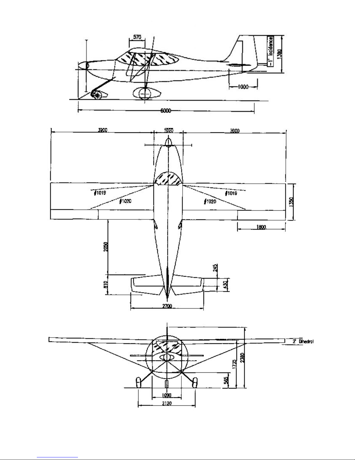
2.0 Overall Dimensions

Terrier T200 LSA Flight Manual Rev No.: 1.0 15 April 2008 Page 5 of 31
3.0 Specifications
Engine
Subaru EA 81
Wing Span
8.70m
Length
6.10m
Empty Weight
334kg
Gross Weight
600kg
Fuel Capacity
88L
Landing Gear Track
2.12m
Baggage
30kg
Design Load (Ultimate +6g/-4g)
+4g/-2g @ 600kg
Airfoil Section
Modified Chris Mk 4

Terrier T200 LSA Flight Manual Rev No.: 1.0 15 April 2008 Page 6 of 31
4.0 Limitations
4.1 Operating limitations, instrument markings and basic placards necessary for the safe operation of the
airplane, its engine, standard systems and standard equipment. Observance of these operating limitations is
required.
4.2 The aircraft shall be operated so that limitations and instructions included in this section are observed.
4.3 Type of Operation
VFR by Day
NO Aerobatics, including Spins.
Side Slips are not approved with flaps extended (flap MAY blank elevator)
4.4 Airspeed Limitations
Airspeed limitations and their operational significance are shown below.
Speed Knots Remarks
VNE Never exceed 125 Do not exceed this speed in any operation.
VNO Normal Operations Speed 38-110
Caution Range 110-120 Only fly at these speeds in smooth air.
VA Maneuvering speed (at Gross
Weight)
85
Do not make full or abrupt control movements above
this speed.
VFE Maximum flap extended speed 70 Do not exceed this speed with flaps down.
VSO 38 Full flaps 600 Kg MTOW
4.5 Airspeed Indicator Markings
Airspeed Indicator Markings and their operational significance are shown below.
Marking Knots Significance
White Arc 38 -70
Full-flap operating range. Lower limit is max. weight Vso in landing
configuration. Upper limit is max. speed permissible with flaps extended
Green Arc 38 -110
Normal operating range. Lower limit is Take-off Safety speed. Upper limit is
max. structural cruising speed
Yellow Arc 110 -120 Operations must be conducted with caution and only in still air
Red Line 125 VNE
4.6 Weights and Loading
Do not exceed under any circumstances.
MTOW Maximum Take Off Weight
600kg
Maximum Landing Weight 600kg

Terrier T200 LSA Flight Manual Rev No.: 1.0 15 April 2008 Page 7 of 31
4.7 Powerplant Limitations
Instrument Yellow Arc Green Arc Red Radial Line/Arc
Oil temp. 60° -90° C 90° -110° C 140° C
Oil Pressure 0,8 – 2,0 bar 2,0 – 5,0 bar 7 bar
Water Temperature 60° -120° C 130° C
Minimum Oil Temperature for
Take Off
50° C
Minimum Oil Pressure In Level Flight or climb 2 bar
In Descent 0.8 bar
Maximum Water
Temperature
130°C
Maximum RPM for all
operations
5000
Full Throttle Static RPM Not Above 4600
Not Under 4200
4.8 Other Limitations
4.9 Authorised Maneuvers and Associated Limitations
Aerobatic maneuvers, including spins, are not permitted.
4.10 Engine Start, Operating Temperature
MAX 50° C MIN -20° C
4.11 Smoking
Prohibited.
4.12 Maximum Air Temperature for Operations
50° C for take off at gross weight.
4.13 Maximum Permissible Number of Occupants
Two (inclu d ing P ilo t) .
4.14 Flights with Door(s) Open
Not permitted.
4.14a Flights with Door(s) Removed (before take-off)
Exercise caution and limited to 80 knots
4.15 Maximum Crosswind Velocity
20 knots (for experts only)
4.16 Maximum Baggage Weight
30 Kg provided rear Centre of Gravity is not exceeded.
4.17 Maximum G Factors
Limit +6g/-4g
4.18 Centre of Gravity
Forward Limit
2242mm aft of DATUM at 600kg
2227mm aft of DATUM at 440kg or less
Rear Limit
2404mm aft of DATUM at all weights
DATUM 2000mm forward of wing leading edge

Terrier T200 LSA Flight Manual Rev No.: 1.0 15 April 2008 Page 8 of 31
5.0 Normal Operations
Speeds for Normal Operation
The following speeds are based on a maximum weight 600 Kg and ma y be used for any lesser weight.
Takeoff: Knots
Take off, 1st Stage Flap 42
Short Field Take off, 1st Stage Flap 40
When Clear obstacles retract flaps and climb at 60-75
Climb, Flaps Up: Knots
Normal 75
Best Rate of Climb, at low altitude 75
Note: Best Obstacle clearance gradient is with 1st Stage Flaps; but do not maintain this
condition for longer than necessary as this may cause excessive engine temperatures
Landing Approach: (MTOW) Knots
Normal Approach, Flaps Full 45
Short Field Approach, Flaps Full. 42
Missing Approach (go around) Knots
Apply full power; allow speed to increase to 42
Retract Flap to 1st Stage
Then retract flap fully and continue to climb at or above 60
Maximum Recommended T ur bulent Air Pe netration Speed 90
Maximum Demonstrated Crosswind Velocity 20

Terrier T200 LSA Flight Manual Rev No.: 1.0 15 April 2008 Page 9 of 31
6.0 Checklist & Procedures
Pre-flight Inspection
Prior to flight, the aircraft should be inspected in accordance with the following checklists.
NOTE
Visually check airplane for general condition during walk-around inspection. In cold weather, remove even small
accumulations of frost, ice or snow from wing, tail and control surfaces. Also, make sure that control rods and
cables are free of ice and move freely.
6.1 Pre-flight Inspection Checklists
1 Fuel
1 Fuel Quantity Check level in tank through visual
2
Water Check
Before first flight of the day & after each refuelling, drain
small quantity of fuel from fuel drain valve & check for
water & sediment.
3 Fuel Filler Cap Check secure on each wing
2 Empennage
2 Control Surfaces Check freedom of movement & security
3
Check freedom of movement & security
3 Right Wing – Trailing Edge
1
Aileron
Check freedom of movement & security
2 Flap Check security
3
Control Rods
Check aileron & flap control bolts & nuts & flap control rod
for security. Check rod ends for freedom of rotation &
excessive movement
4 Pitot Tubes
1 Static & Dynamic Source Remove cup, check for blockage
5 Right Wing
1 Wing Control for damages
2 Main Wheel & Tyres Check for security. Proper tyre inflation & wear or damage
3
Wing Mount Bolts and Strut s
Check for security
6 Nose
1 Propeller & Spinner Check for nicks & security
2 Cowling Remove and check security of engine components &
systems, particularly mounts, spark plugs, wiring, fuel
lines, baffles, check for oil leaks.
3
Engine Oil & Cooling Liquid
Level
Check & top up if necessary. Clean up any spilt oil.
4 Cowling Replace and check clips fastened & secure
7 Left Wing
1
Main Wheel & Tyre
Check for security. Proper tyre inflation or damage
2
Wing Mount Bolts and Strut s
Check for security
3 Wing Control for damages
8 Left Wing – Trailing Edge
1 Aileron Check freedom of movement & security
2 Flap Check security
3
Control Rods
Check aileron & flap control bolts & nuts & flap control rod
for security. Check rod ends for freedom of rotation &
excessive movement
9 -Cabin
1 Flight manual Available in the aircraft
2 Ignition Switches OFF
3 Master Switch OFF

Terrier T200 LSA Flight Manual Rev No.: 1.0 15 April 2008 Page 10 of 31
4 Fuel Shutoff Valve ON
5
Seatbelts and Shoulder
Harnesses
Check condition and security
6
Ailerons Check for free rotation & excessive movement.
7
Elevator Check for free rotation & excessive movement,
8
Rudder Check free security & free movement.
9 Flap Control Check for free movement & bolts secure.
10 Throttle controls Check for full & free travel
11 Brake lever Check for free travel & pressure.
 Loading...