

Page 1
Portable
Roughness Tester
54-410-500-0/54-410-511-0
54-410-600-0/54-410-622-0
Instruction Manual
Page 2

Page 3

CONTENTS
1. Description 2
2. Specications 3
3. Measurement Parameters 4
4. Features 5
5. Battery Installation/Replacement 6
6. Controls and Digital Display 6
7. Calibration 7
8. Operation 8
9. Probes 9
10. Probe Replacement 11
11. RS-232 Output 12
12. Maintenance 13
13. Accessory: Height Stand 14
Page 4

1. Description
The Roughness Tester II is a portable, battery-powered instrument for checking
surface roughness with the measured values displayed on a digital readout. This
instrument can be used in the laboratory, inspection area, shop, or wherever onsite surface roughness testing is required.
NOTE: Even though this instrument is designed and built to withstand the rigors of handling and use, it is a precision instrument and
should be treated with care to assure measurement accuracy and
reliable performance.
All Roughness Testers include:
• Roughness unit
• General purpose probe
• Certied specimen (nominal)
• 9 volt alkaline battery
• Screwdriver
Model 54-410-500-0, (54-410-511-0 with RS-232) are furnished with a certied
specimen and 0.0004" probe.
* Probe supplied with a 90° conical diamond stylus, 0.0004" (10µm) radius per
ANSI-B46, ISO and MIL specs.
Model 54-410-600-0, (54-410-622-0 with RS-232) are furnished with a certied
specimen and 0.0002" probe.
* Probe supplied with a 90° conical diamond stylus, 0.0002" (5µm) radius per
DIN-4768 and certain ISO specs.
2
Page 5
2. Specications
Measuring ranges: Ra-0.03 µm~6.3 µm/1 µ "~250 µ"
Rz-0.2 µm~25.0 µm/8 µ "~999 µ"
Display Resolution: 0.01 µm/1 µ"
Cut-off: 0.25mm/0.8mm/2.5mm, ANSI 2RC Filter
Display: 3-digital LCD
Measure Accuracy: Meets ISO and DIN standards
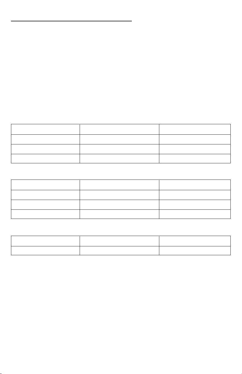
Traverse lengths and Evaluation lengths:
Cut-off = 0.25mm/0.010"
Traverse length Evaluation length Numbers of cutoff
0.75mm/0.030" 0.25mm/0.010" 1
1.25mm/0.050" 0.75mm/0.030" 3
1.75mm/0.070" 1.25mm/0.050" 5
Cut-off = 0.8mm/0.030"
Traverse length Evaluation length Numbers of cutoff
1.2mm/0.048" 0.8mm/0.032" 1
3.0mm/0.119" 2.4mm/0.095" 3
4.5mm/0.178" 4.0mm/0.157" 5
Cut-off = 2.5mm/0.10"
Traverse length Evaluation length Numbers of cutoff
3.0mm/0.119" 2.5mm/0.10" 1
Probe type: Piezoelectric
Maximum stylus force: 15.0mN/1500mgf
Power: 9-volt consumer-type alkaline battery
Battery capacity: approx. 3000 measurements
Operating temperature: 10°~45° C/50°~113° F
Storage temperature: 0°~60° C/32°~147° F
3
Page 6
3. Measurement Parameters
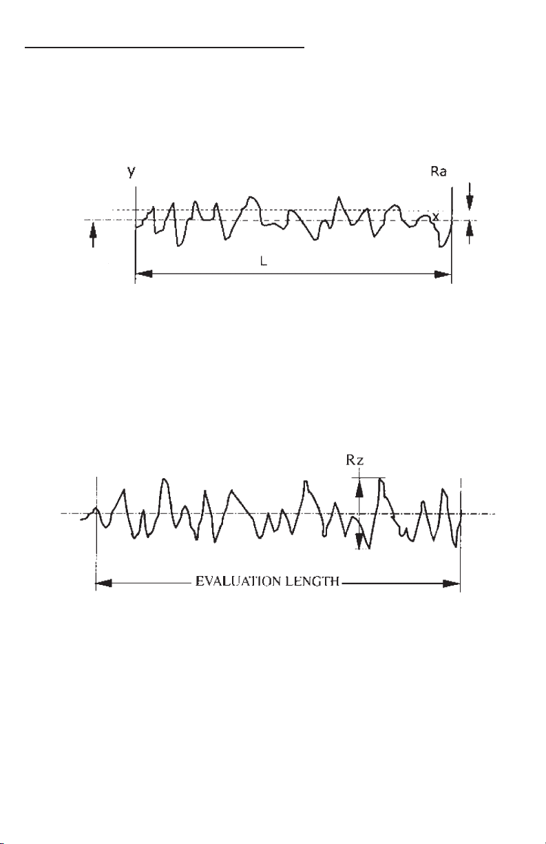
Ra Roughness Average— the arithmetic average height of roughness
irregularities measured from a mean line within the evaluation length(L).
MEAN LINE
Ra= 1/L ∫ | y | dx≈(y1+y2+y3+…+yn / n
Rz Maximum Roughness Depth— the largest of the peak-to-valley
roughness depths in the evaluation length.
4
Page 7
4. Features
10
13
12
1
11
2
3 4 5
9
6
7
8
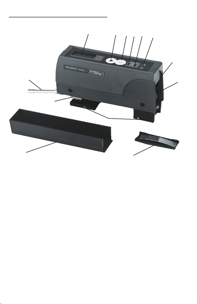
1. Digital display
2. Start/On button
3. Parameter selection button
4. Cut-off selection button
5. Traverse length switch
6. in/mm switch
7. Output connector (optional)
8. Battery compartment (9V alkaline)
9. Battery compartment cover
10. Protective cover
11. 2 "V" feet
12. Probe holding block
13. Probe
5
Page 8
5. Battery installation / replacement (Alkaline ONLY)
1. Remove Protective Cover from the gage base and slide Battery Compartment
Cover off end of the gage.
2. Install/replace battery and replace Battery Compartment Cover.
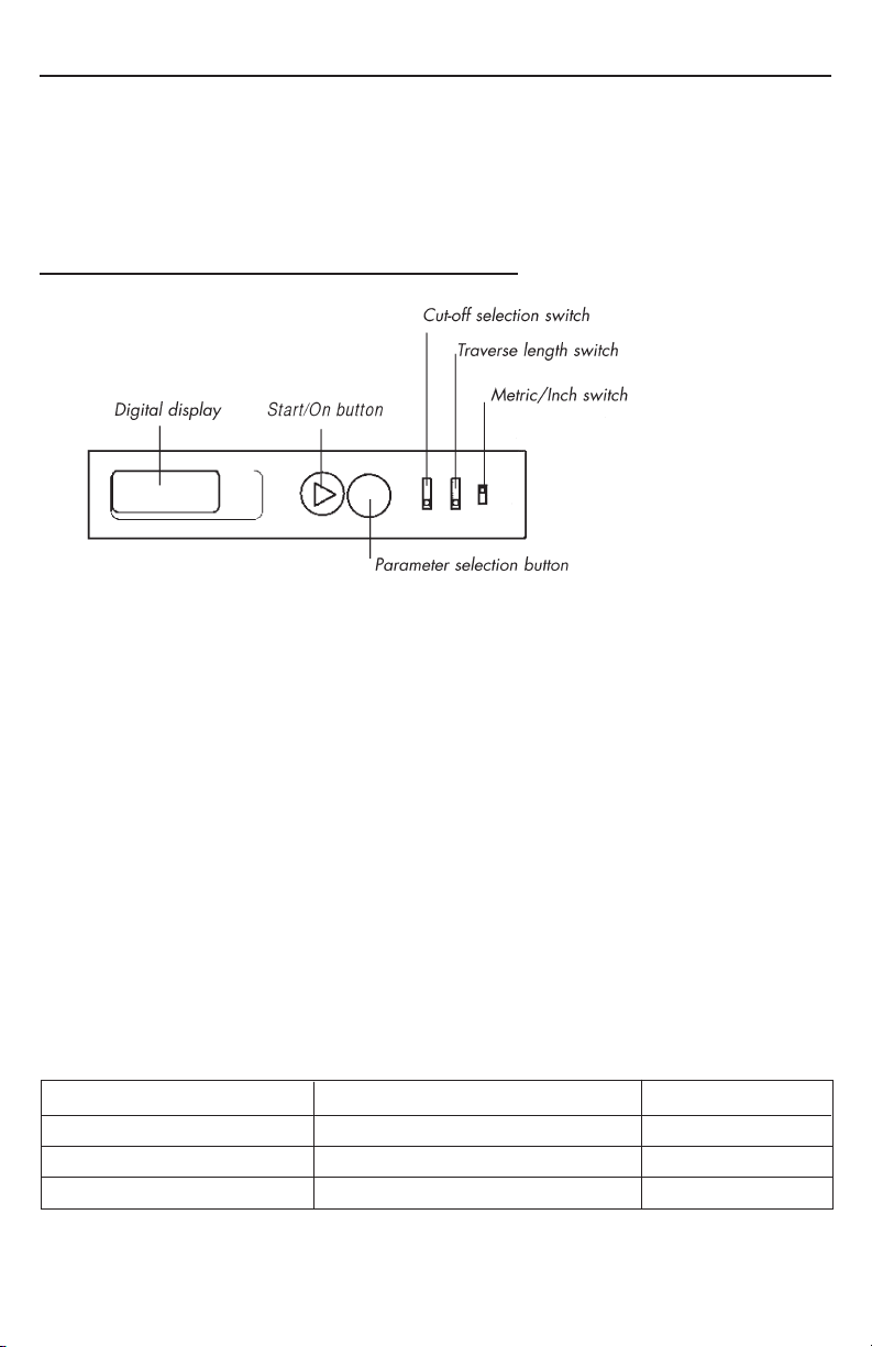
6. Controls and digital display
1. Press Start/On button once, it should display "1-000". If there is no display or
if it displays "8-888", this indicates a weak battery, and you must remove and
replace the battery. The tester will turn off automatically after several minutes.
2. Set in/mm switch for Metric (µm) or Inch (µ"). Set cut-off selection switch for
0.25mm, 0.8mm, 2.5mm, based on the roughness value to be estimated.
Refer to Table 1.
Set traverse length switch for 1,3 or 5. Refer to Specication section's traverse
length for detail.
3. Press and release "Start/On" button. The readout should display
"1-X.XX" (Ra). If the readout displays "8-888", it is indicating a low battery and
you need to replace the battery.
4. If the Ra or Rz value displayed is out of the measuring range which accordance
with selected Cut-off, then re-select the Cut-off. Refer to table 1.
5. The digital display will alternate between "2-X.XX"(Rz) by pressing and releas-
ing the parameter selection button.
Table 1:
Measuring ranges (Ra) Measuring ranges (Rz) Cut-off (lc)
0.03µm Ra 0.1µm 0.1µm Rz 0.5µm 0.25mm
0.1µm Ra 2.0µm 0.5µm Rz 10.0µm 0.8mm
2.0µm Ra 6.3µm 10.0µm Rz 50.0µm 2.5mm
6
Page 9
7. Calibration
Prior to operating the tester, its calibration should be checked.
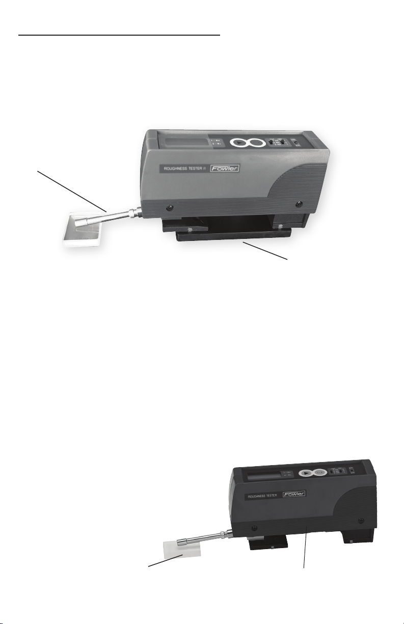
1. The tester is calibrated using the reference specimen. Set cut-off selection
switch to position "0.8mm", set the traverse length switch to position "5", and
set the inch/mm switch to position "Metric". Place the tester on the calibration
plate. Make sure that the probe stylus is in the middle of the specimen.
Probe
Calibration plate
2. Press and release the Start/On button and take a reading from the center
of the specimen. If the reading is within ±0.02µm of the value stated on the
calibration certicate, calibration is within tolerance. If the reading differs from
the value stated on the calibration certicate by more than ±0.02µm, take ad-
ditional readings around the central area of the specimen. If the reading still
differs by more than the allowable tolerance, recalibrate the tester using the
procedure below.
A. Using a screwdriver, carefully adjust the calibration control as follows:
• Clockwise to increase the displayed Ra value, or
• Counter clockwise to decrease the displayed Ra value.
B. After adjusting the calibration control, remeasure the reference specimen
to assure that the tester is within the calibration tolerance.
C. When calibrating with a Small Bore
Probe or Groove Bottom Probe, the
probe should be in the 180° position.
Make sure that the tester base is at
the same height as the surface of the
calibration specimen.
Calibration plate
Calibration plate or Height Stand
7
Page 10
8. Operation
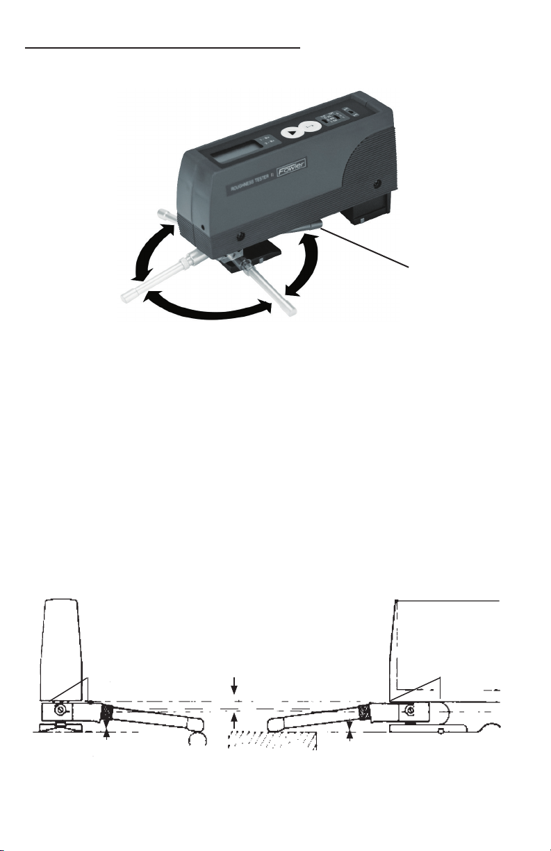
The tester will operate in any one of four probe positions. Selection of the proper
position depends on the application.
270°
"Closed Position"
180°
90°
When changing probe positions, gently grasp the probe by its body, (NEVER
HANDLE THE PROBE BY ITS SKID OR STYLUS END). During the measuring
cycle, the probe stylus and skid should be in contact with a surface and the setup
should be properly aligned otherwise any readings obtained are not valid and
are not to be used for measurement or tester performance evaluation purposes.
The tester can be hand held or placed on a surface in any attitude. It will operate
in virtually any position horizontally/vertically, or at any angle in between, even
upside-down.
With the probe positioned on the workpiece surface to be measured, carefully
adjust the tester and workpiece setup so that the Reference line (the upside of
the Probe Mounting Block) is parallel to the bottom of the tester housing and
parallel to the workpiece’s surface (see below). This ensures that the probe skid
and stylus are ush to the work surface even though the probe body will be at an
angle to the work surface.
Reference Line
Within ±.100"/±2.5mm
Parallel
Reference Line
Within ±.100"/±2.5mm
8
Page 11
9. Probes
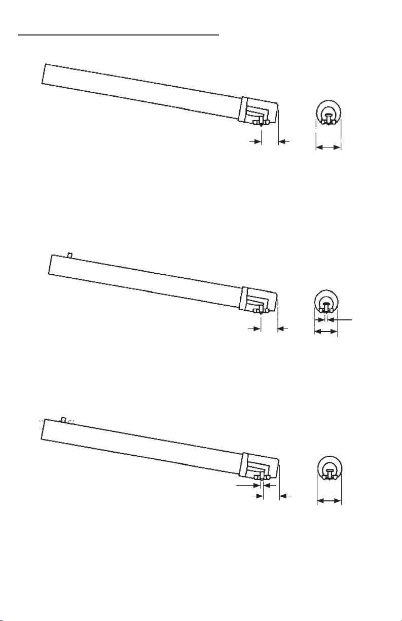
General Purpose Probe (54-400-319-0 or 54-400-326-0)
3.8mm
7.0mm
• For most surface roughness applications. 54-400-319-0 has a 90° conical dia-
mond stylus, 0.0004"/10µm radius per ISO specications. 54-400-326-0 has a
90° conical diamond stylus, 0.0002"/5µm radius per DIN standards.
Traverse Chisel Probe (54-420-301-0)
0.5mm
3.8mm
7.0mm
• For gaging sharp edges or small O.D.’s where the probe is aligned at 180° or in
closed position 90° diamond chisel stylus, 0.0004"/10µm radius.
Parallel Chisel Probe (54-420-302-0)
0.5mm
3.8mm
7.0mm
• For gaging sharp edges or small O.D.’s where probe is perpendicular (in 90°
or 270° position) to axis of traverse. 90° diamond chisel stylus, 0.0004"/10µm
radius.
9
Page 12
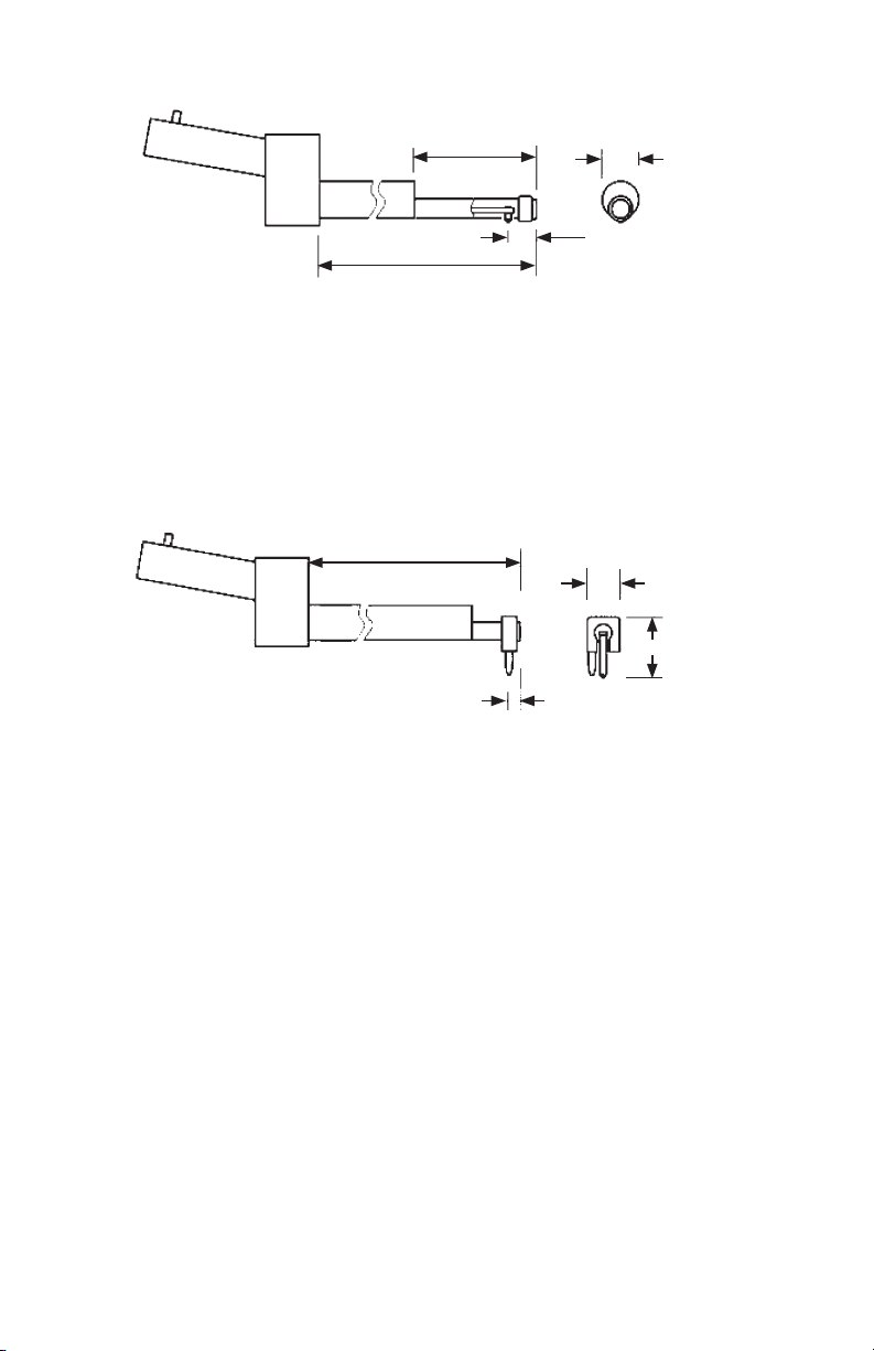
Small Bore Probe (54-420-321-0 or 54-420-327-0)
20mm
4.0mm
60.0mm
6.0mm
• For measuring small bores (min. inside diameter of 5.0mm, up to a depth of
15.0mm). 90° conical diamond stylus, 0.0004"/10µm radius for 54-420-321-0;
0.0002"/5µm radius for 54-420-327-0.
Groove Bottom Probe (54-420-328-0)
60mm
5.0mm
10.0mm
2.5mm
• For measuring the bottoms of "O" ring grooves, recesses and holes to a depth
of 6.0mm. Also used for short lands and shoulders. 90° conical diamond stylus,
0.0004"/10µm radius.
10
Page 13

10. Probe Replacement
1. Turn the tester upside down and swivel the probe to its 90° position.
2. Loosen the knurled locking collar by turning it counter-clockwise approximately
3 turns until the access slot is aligned with the probe pin slot in the probe
mounting block. Grasp the probe by its body section and carefully withdraw
the probe from its mounting block and the knurled locking collar.
Do not grasp the probe by its skid and stylus end. Do not remove the
knurled locking collar from the probe mounting block loosen it only
enough to slide the probe out easily.
3. Reverse the procedure to install a probe, aligning the pin on the bottom of the
probe body with the access slot in the locking collar.
Make sure that the probe is fully inserted into the probe mounting block
so that the electrical connector is completely engaged before tightening
the locking collar. Finger tighten only.
4. Check the tester's calibration after changing probes.
11
Page 14

11. RS-232 Output
For Part Number 54-410-511-0 and 54-410-622-0
The tester's digital output feature permits measurement results to be transmitted
to an external device such as a printer, computer or data collection system.
For further information concerning the RS-232 output, please contact the
Technical Department at the phone number listed on the back cover of this
manual.
12
Page 15

12. Maintenance
Protection & Storage
To protect the tester when not in use, always return the probe to its closed position and replace the Protective Cover on the tester unit. When not in use, always
keep the tester and its accessories in the tted case.
Cleaning
To clean the tester unit, use a soft, lint-free cloth moistened with a mild, non-abra-
sive, liquid cleaning agent. Using a magnier, periodically inspect the probe skid
and stylus area for dust, dirt or other contamination. To clean the probe skid and
stylus, use a soft (camel’s hair) artist’s brush moistened with denatured alcohol.
Repairs
If you encounter any trouble with the tester please contact the Service Department at the phone number listed on the back cover of this manual.
Do not disassemble the unit or attempt any further repairs.
13
Page 16
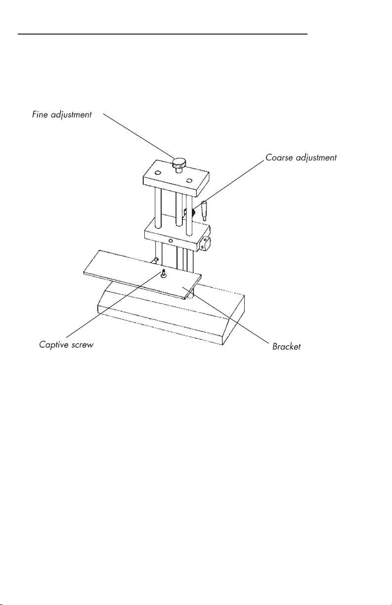
13. Accessory: Height Stand (54-400-896-0)
The Height Stand is intended to be used on a surface plate or other suitably at
surface to measure workpiece surfaces ranging in height from ush with the work
surface to a maximum height of approximately 6.9"/175mm. The tester probe can
be in either its 90° or 180° position.
1. Mount the tester in the bracket on the height stand using the captive screw in
the base of the bracket. The screw mates with the tapped hole in the bottom of
the tester housing. Tighten the screw nger tight.
2. Position the height stand so that the probe is above the workpiece surface to
be measured. Use the coarse height adjustment to bring the probe skid and
stylus slightly in contact with the surface. Use the ne adjustment to make the
Reference Line (the upside of the mounting block) parallel to the bottom of the
tester housing.
3. Once the setup is correctly adjusted and the probe is properly positioned on
the workpiece surface, gently press and release the Start button on the tester
to make the measurement.
14
Page 17

Notes
Page 18

Notes
Page 19

Page 20

Fowler High Precision
66 Rowe Street • Newton, Massachusetts 02466
1-800-788-2353 • (617) 332-7004 • (617) 332-4137 fax
 Loading...