

Page 1

PM-2
- Reference Manual -
professional studio monitor
Safety Instructions
Introduction &
Setup Instr
Setup Instr
Bac
k Panel Ov
Product Specifica
Ca
b
le
and W
Product Cleaning Instr
Dec
lar
a
uctions
uctions - continued
ti
o
n
Unpac
e
r
iring
of
EC Dir
view
tions
In
f
o
rm
ectiv
k
ing
a
u
ctions
tion
e
p-2
p-3
p-4
p-5
p-6
p-7
p-7
p-7
p-8
p-1
Page 2
CAUTION
RISK OF ELECTRIC SHOCK
DO NOT OPEN
CAUTION: TO REDUCE THE RISK OF ELECTRIC SHOCK,
DO NOT REMOVE COVER (OR BACK).
NO USER - SERVICEABLE PARTS INSIDE.
REFER SERVICING TO QUALIFIED SERVICE PERSONNEL.
"WARNING"
"TO REDUCE THE RISK OF FIRE OR ELECTRIC SHOCK,
DO NOT EXPOSE THIS APPLIANCE TO RAIN OR
MOISTURE."
SAFETY INSTRUCTIONS
CAUTION:
TO PREVENT ELECTRIC SHOCK, MATCH WIDE BLADE OF
PLUG TO WIDE SLOT, FULLY INSERT.
ATTENTION:
POUR EVITER LES CHOCS ELECTRIQUES, INTRODUIRE
LA LAME LA PLUS LARGE DE LA FICHE DANS LA BORNE
CORRESPONDANTE DE LA PRISE ET POUSSER JUSQU'
AU FOND.
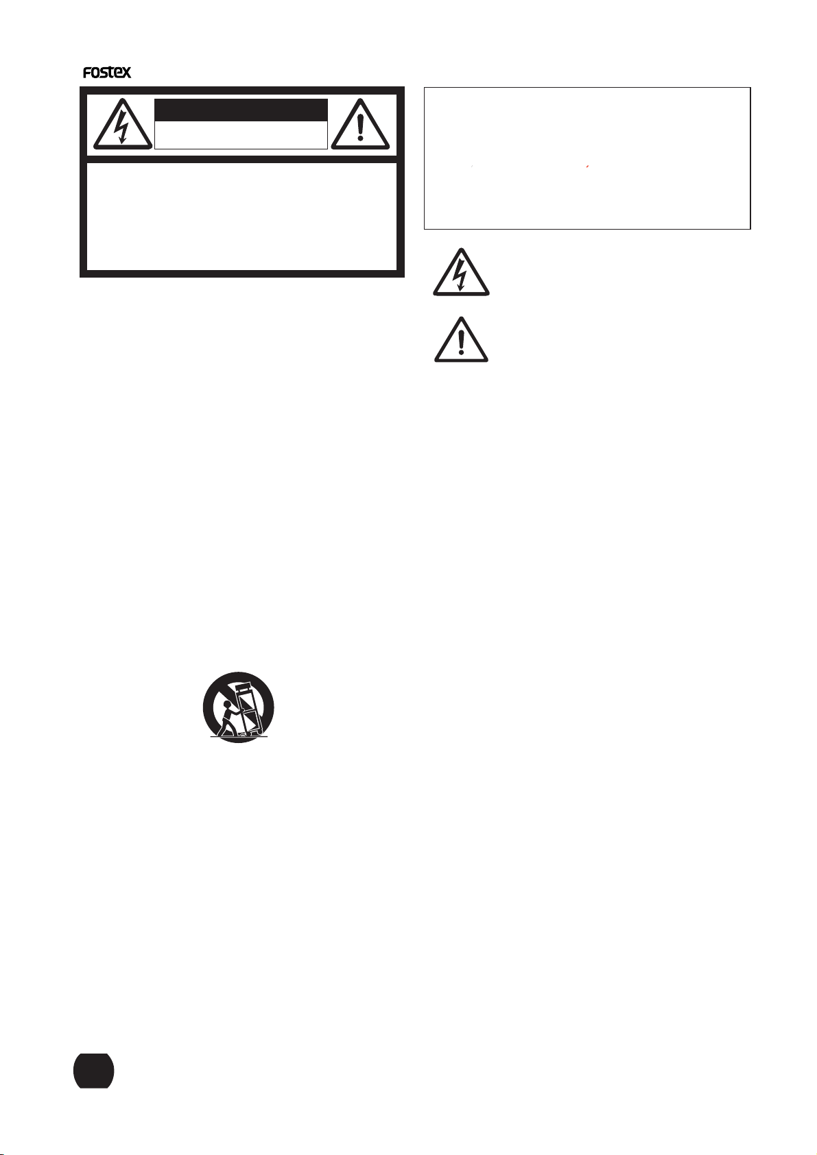
The lightning flash with arrowhead symbol, within an equilateral
triangle, is intended to alert the user to the presence of
uninsulated "dangerous voltage" within the product's enclosure
that may be of sufficient magnitude to constitute a risk of electric
shock to persons.
The exclamation point within an equilateral triangle is intended
to alert the user to the presence of important operating and
maintenance (servicing) instructions in the literature
accompanying the appliance.
Read Instructions - All the safety and operating instructions
1.
should be read before the appliance is operated.
2.
Retain Instructions - The safety and operating instructions
should be retained for future reference.
Heed Warnings - All warnings on the appliance and in the
3.
operating instructions should be adhered to.
Follow Instructions - All operating and use instructions should
4.
be followed.
Water and Moisture - The appliance should not be used near
5.
water - for example, near a bathtub, washbowl, kitchen sink,
laundry tub, in a wet basement, or near a swimming pool, and
the like.
Carts and Stands - The appliance should be used only with a
6.
cart or stand that is recommended by the manufacturer.
An appliance and cart combination should be moved with care.
Quick stops, excessive force, and uneven surfaces may cause
the appliance and cart combination to overturn.
Wall or Ceiling Mounting - The appliance should be mounted to
7.
a wall or ceiling only as recommended by the manufacturer.
Ventilation - The appliance should be situated so that its location
8.
or position does not interfere with its proper ventilation.
For example, the appliance should not be situated on a bed,
sofa, rug, or similar surface that may block the ventilation
openings; or, placed in a built-in installation, such as a bookcase
or cabinet that may impede the flow of air through the ventilation
openings.
Heat - The appliance should be situated away from heat sources
9.
such as radiators, heat registers, stoves, or other appliances
(including amplifiers) that produce heat.
Power Sources - The appliance should be connected to a power
10.
supply only of the type described in the operating instructions or
as marked on the appliance.
11.
Grounding or Polarization - The precautions that should be taken
so that the grounding or polarization means of an appliance is
not defeated.
Power Cord Protection - Power supply cords should be routed
12.
so that they are not likey to be walked on or pinched by items
placed upon or against them, paying particular attention to cords
at plugs, convenience receptacles, and the point where they
exit from the appliance.
Cleaning - The appliance should be cleaned only as
13.
recommended by the manufacturer.
Unplug this apparatus during lightning storms or when
14.
unused for long periods of time.
Object and Liquid Entry - Care should be taken so that objects
15.
do not fall and liquids are not spilled into the enclosure through
openings.
Damage Requiring Service - The appliance should be serviced
16.
by qualified service personnel when:
The power supply cord or the plug has been damaged; or
A.
Objects have fallen, or liquid has been spilled into the appliance; or
B.
The appliance has been exposed to rain; or
C.
The appliance does not appear to operate normally or
D.
exhibits a marked change in performance; or
The appliance has been dropped, or the enclosure damaged.
E.
Servicing - The user should not attempt to service the appliance
17.
beyond that described in the operating instructions.
All other servicing should be referred to qualified service
personnel.
The appliance should be situated away from drops of water or
18.
spray of water.
Objects containing liquid such as vase must not be put on the
19.
appliance.
The appliance is not completely isolated from the power supply
20.
even if the power switch is at off position.
21.
The apparatus shall be used in an open area.
p-2
Page 3
Introduction
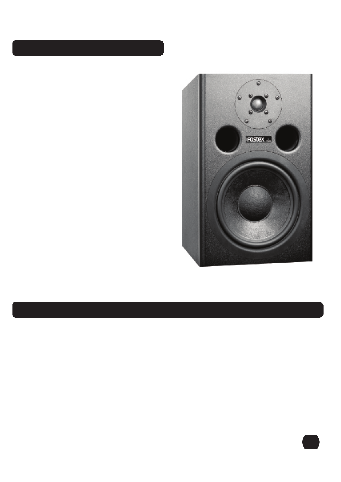
Thank you for purchasing the Fostex PM-2
Professional Studio Monitor. As with all
Fostex products, the PM-2 has been
designed to provide superlative performance,
unquestioned reliability and exceptionally
high value.
The PM-2 was specifically engineered to fulfill
all of your critical near-field monitoring needs
and is emblematic of the years of experience
Fostex has had in the professional audio
marketplace. The PM-2 takes full advantage
of internal bi-amplification and employs two
state of the art amplifiers that utilize highquality discrete bipolar output devices. The
8" woofer and 1" tweeter were expressly
designed for high output, ultra low distortion
and incorporate the latest technologies and
manufacturing techniques.
Please take the time to thoroughly read this
manual so that you may take full advantage
of all the benefits of the Fostex PM-2
Professional Studio Monitor.
Unpacking
Prior to unpacking your Fostex PM-2 Studio Monitor, carefully inspect the packing material for
excessive damage. Once it has been determined that the packing material has not been
compromised, carefully unpack the PM-2 Studio Monitor and inspect it carefully for obvious
damage. Fostex takes great care in designing packing materials that will survive most expected
impacts during shipping. If any damage is discovered during the inspection process, contact your
Fostex dealer so that this issue can immedicately be addressed.
p-3
Page 4
Setup Instructions
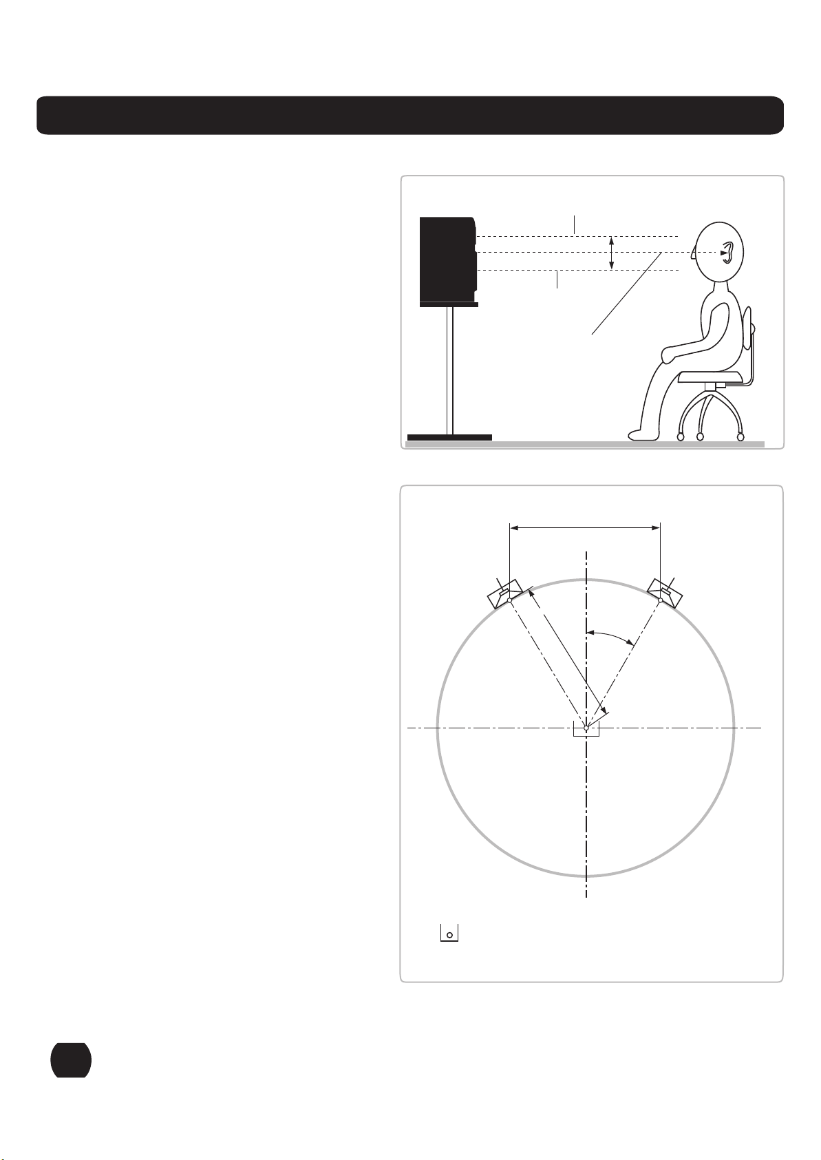
Monitoring Distane = 1 to 2 meters
After carefully unpacking the PM-2
Professional Studio Monitor, it is now
time to setup the monitors for the best
acoustic performance in your studio.
The PM-2 was designed to be used at a
monitoring distance of 1 to 2 meters,
typically referred to as the near-field.
Monitoring Height = the acoustic
center aimed at seated ear height
It is recommended that the PM-2 be
located in such a way that the acoustic
center is located at, or about, seated ear
height (see Figure 1). If this is not
possible, it may be necessary to tilt/aim
the monitor at the listeners ears.
Monitoring Angle = 60 Degrees
The monitoring angle between the left
and right monitors and the listening
position should equal 60 degrees. The
easiest way to determine this is to place
the speakers in such a way that the
distance between the left and right
monitor is equal to the monitoring
distance / listening position (see Figure
2). It is also recommended that both
speakers be "toed-in" towards the
listening position.
Figure 1
Figure 2
Left
Center of the tweeter
Center of the woofer
Mid-point of the woofer and tweeter
B
D = B
30°
Right
r = B
B
Additional Information
The PM-2 was designed to be mounted
vertically. This provides for the most
accurate frequency response, reduces
acoustic boundary interference and
provides optimum cooling performance
for the heat sink that is located on the
back of the studio monitor. If it is not
possible to mount the monitors vertically,
then the monitors should be placed with
the woofers inside and the monitors
"toed-in" towards the listening area.
p-4
Reference listening position
B: loudspeakerbase width
D: monitoring distance
Page 5

Setup Instructions -
Once the studio monitors have been placed in their final location, it is time to proceed to connecting you
PM-2 studio monitors to the mixing console or digital workstation. Connection to the PM-2 can be made
using XLR or TRS connectors. The gain control on the back of the monitor allows continuously variable
adjustments to match most input types from -10dBV to +4dBu. Their input is electronically balanced and is
compatible with unbalanced sources, although this may require an adapter. The connection of the PM-2 to
the console/digital workstation should be done in the following order.
Step 1: Make sure that all equipment has been powered down.
Step 2: Confirm that all gain controls, on the monitor and the source, are set to the minimum setting.
Step 3: Connect the source to the PM-2 monitor.
Step 4: Power up the all source equipment and then turn on the PM-2 last.
Step 5: Set the gain of both monitors at medium setting and slowly bring up the gain of the console.
Step 6: Adjust the gain of both monitors for balance and for best signal to noise ratio.
Once the above steps have been completed, you are ready to use your PM-2 monitors. It is recommended
that you now play some familiar audio material and make any final adjustments, as far as placement or
level, to get the optimum performance in your monitoring environment.
continued
p-5
Page 6
Back Panel Overview
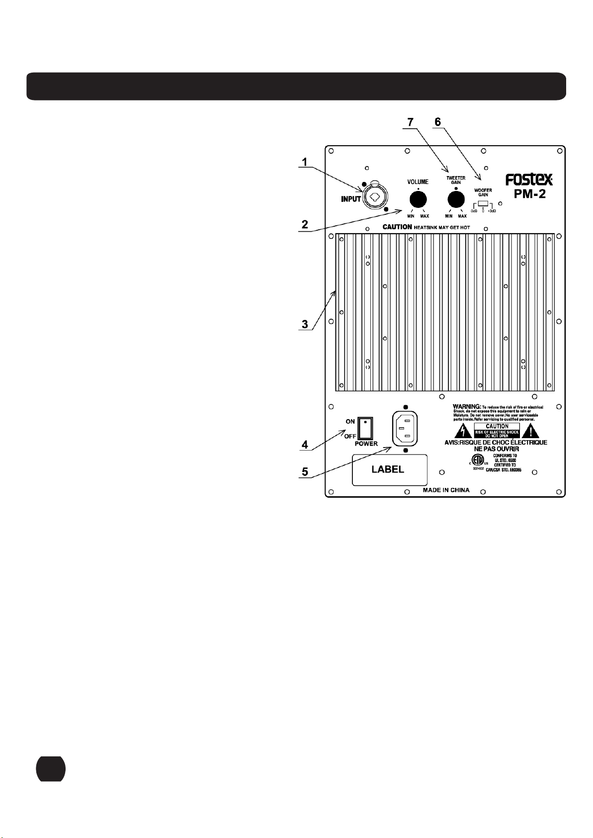
1. XLR & TRS Combination Input
This input is an electronically balanced input and
is compatible with both -10dBV and +4dBu
signals.
2. Continuously variable gain control
This control adjusts the input level to the internal
amplifiers.
3. Heatsink
The heatsink dissipates heat from the amplifier. It
is important the heatsink receives proper
ventilation and is not placed near any sources of
heat.
4. Power Switch
Turns power to the amplifier section on or off.
On-position is the spot side.
5. Standard IEC Power Input
This powor terminal should be used with a
properly grounded three pin power cable, such as
the one provide with the product.
6. Low Frequency Adjustment
The PM-2 allows you to adjust its low frequency
response to get suit its environment.
There may be cases where a slight adjustment
is necessary in order to better match the
acoustic characteristics of the room.
To make this adjustment you may boost or
cut the PM-2's low frequency @ 60Hz by 3dB
simply by turning the switch to the right or the
left respectively.
There are 3 positions:-3dB,0dB,+3dB.
The factory preset position is the center,0dB position.
7. High Frequency Adjustment
The High Frequency adjustment tailors the overall high frequency response by +/-3dB
above 5kHz. This control is a variable knob with no preset position. In the extreme
positions a full +/-3dB can be achieved. Leave this adjustment in the normal "0dB"
position unless:
• You want to subtly brighten or darken the sound of the speakers
• You want to compensate for any HF hearing loss
• You just like to mix on the bright or dull side
If your mixes consistently sound dull or dark when you listen elsewhere, this usually
indicates that you monitors are too bright relative to your normal hearing. A bit less high
frequency energy usually fixes this, and you can force the mix in this direction by
reducing the high frequency output of the monitors by turning the knob in the -3dB
direction. The converse is true if your mixes are consistently sounding bright and present.
p-6
Page 7
Product Specifications
Cabinet Dimensions
254mm (W) x 411mm (H) x 300mm (D) includes heatsink
271mm (D) cabinet only - no heatsink
10" (W) x 16
10 3/5" (D) cabinet only - no heatsink
Net Weight
14.7 Kg
32.4 Pounds
Gross Weight (includes all packing material)
16.2 Kg
35.7 Pounds
Frequency Response
Free-Field Frequency Response: ± 2dB 50Hz to 20KHz
Low Frequency Cutoff: 40Hz (-10dB)
High Frequency Cutoff: 22KHz (-10dB)
Low Frequency Control:
High Frequency Control:
Product improvement may warrant a change of specifications, newer material or cosmetics. Changes in
specifications and features may be made without notice or obligations.
1/8
" x 11
4/5
" (D) includes heatsink
± 3dB (at 60Hz)
± 3dB (at 5KHz)
Amplifier Power
High Frequency: 120 Watts
Low Frequency: 120 Watts
Amplifier Distortion
< 0.05% THD @ 50Watts / 6Ohm 20Hz-20KHz
Amplifier Signal to Noise Ratio
>90dB
20Hz - 30KHz Not Weighted
Amplifier Slew Rate
10V/µsec
Power Requirements
US: 120VAC~60Hz
EUR/UK: 230VAC~50/60Hz
Power Consumption
US: 110 Watts
EUR/UK: 120 Watts
Cable and Wiring Information
User high-quality, shielded cables to connect your mixing console, workstation or other source to your
monitors. Foil-shielded cables, such as Belden 8451, 8761, or 9501 should do quite well. Other high
quality cables are available and those that incorporate better shielding will yield an overall higher noise
rejection, lowering your systems susceptibility to external interference. Another important tip to keep in
mind when wiring your system is to route all line level cables away from the AC and other power
sources, this will reduce the probability of having AC hum emanating from your studio monitors.
HOT (+)
COLD (-)
SHIELD (GROUND)
XLR
PIN 2
PIN 3
PIN 1
TRS
TIP
RING
SHIELD
RCA
TIP
SHIELD
Product Cleaning Instructions
Prior to cleaning the PM-2 monitor the power must be disconnected from the PM-2 monitor. Once the
power has been terminated, cleaning can be accomplished using a damp (not wet) cleaning rag. A light
common household cleaner can also be used, but care must be taken not to use harsh cleaning fluids.
Regular dusting or cleaning with a damp rag will keep your product looking new for years.
p-7
Page 8
Declaration of EC Directive
This equipment is compatible with the EMC Directive (89/336/EEC) - Directive on approximation of member
nation's ordinance concerning the electromagnetic compatibility and with the Low Voltage Directive (73/23/EEC)
- Directive on approximation of member nation's ordinance concerning electric equipment designed to be used
within the specified voltage range.
The Affect of Immunity on This Equipment
The affect of the European Specification EN50082-1 (coexistence of electromagnetic waves - common
immunity specification) on this equipment are as shown below.
In the electrical fast transient/burst requirements, surge, conducted disturbances by radio-frequency fields, power
frequency magnetic field, radiate electromagnetic field requirements and static electricity discharging environment,
this could be affected by generation of noise in some cases.
FOSTEX DISTRIBUTORS LIST IN EUROPE
* Including non-EU countries (as of June, 2003)
<AUSTRIA>
NAME: ATEC Audio-u.Videogeraete VertriebsgesmbH.
ADD: Im Winkel 5, A-2325 Velm, Austria
TEL: (+ 43) 2234-74004, FAX: (+43) 2234-74074
<DENMARK>
NAME: SC Sound ApS
ADD: Malervej 2, DK-2630 Taastrup, Denmark
TEL: (+45) 4399-8877, FAX: (+45) 4399-8077
<FINLAND>
NAME: Noretron Oy Audio
ADD: P. O. Box 22, FIN-02631 Espoo, Finland
TEL: (+358) 9-5259330, FAX: (+358) 9-52593352
<FRANCE>
NAME: Sennheiser France
ADD: 128 bis, avenue Jean-Jaures, 94851 Ivry-sur-Seine
Cedex, France
TEL: (+33) 1 4987 0300, FAX: (+33) 1 4987 0324
<GERMANY>
NAME: Mega Audio GmbH
ADD: Stromberger Str. 32, 55411 Bingen, Germany
TEL: (+49) 6721-94330, FAX: (+49) 6721-32046
<GREECE>
NAME: Bon Studio S. A.
ADD: 6 Zaimi Street, Exarchia, 106.83 Athens, Greece
TEL: (+30) 210-3809-605,606,607,608
FAX: (+30) 210-3845-755, 210-3827-868
<THE NETHERLANDS>
NAME: IENKE ROOS AUDIO B. V.
ADD: Kuiperbergweg 20, 1101 AG Amsterdam, The
Netherlands
TEL: (+31) 20-697-2121, FAX: (+31) 20-697-4201
<NORWAY>
NAME: Fitzpatrick
ADD: P.B.4316 Nydalen, 0402 Oslo, Norway
TEL: (+47) 23 400 380, FAX: (+47) 23 400 389
<PORTUGAL>
NAME: Caius - Tecnologias Audio e Musica, Lda.
ADD: Praca do Bom Sucesso, No 61 Bom Sucesso Trade
Center, Escritorio 701/702, 4150-146 Porto, Portugal
TEL: (+351) 22-608-06-10, FAX: (+351) 22-608-06-29
<SPAIN>
NAME: Letusa
ADD: C/Laguna 10, 28923 Alcorcon, Madrid, Spain
TEL: (+34) 91-4862800, FAX: (+34) 91-6414597
<SWEDEN>
NAME: TTS Scandinavia AB
ADD: Kavallerivagen 24, 172 48 Sundbyberg, Sweden
TEL: (+46) 8-59798000, FAX: (+46) 8-59798001
<SWITZERLAND>
NAME: Audio Bauer Pro AG
ADD: Bernerstrasse-Nord 182, CH-9064 Zurich, Switzerland
TEL: (+41) 1-4323230, FAX: (+41) 1-4326558
p-8
<ICELAND>
NAME: I. D. elrf. electronic Ltd.
ADD: ARMULA 38 108 REYKJAVIK, ICELAND
TEL: (+354) 588 5010, FAX: (+354) 588 5011
<ITALY>
NAME: Proel S. p. A.
ADD: Zona Via Alla Ruenia, 37/43,
64027-Sant'Omero(Teramo), Italy
TEL: (+39) 0861-81241, FAX: (+39) 0861-887862
<UK>
NAME: SCV London
ADD: 40 Chigwell Lane, Oakwood Hill Industrial Estate,
Loughton, Essex IG10 3NY U. K.
TEL: (+44) 020-8418-0778, FAX: (+44) 020-8418-0624
 Loading...