

Page 1

DVD MULTITRACK RECORDER
Owner’s Manual
Page 2
DVD Multitrack Recorder DV824DVD Multitrack Recorder DV824
DVD Multitrack Recorder DV824
DVD Multitrack Recorder DV824DVD Multitrack Recorder DV824
CAUTION
RISK OF ELECTRIC SHOCK
DO NOT OPEN
CAUTION: TO REDUCE THE RISK OF ELECTRIC SHOCK,
DO NOT REMOVE COVER (OR BACK).
NO USER - SERVICEABLE PARTS INSIDE.
REFER SERVICING TO QUALIFIED SERVICE PERSONNEL.
"WARNING"
"TO REDUCE THE RISK OF FIRE OR ELECTRIC SHOCK,
DO NOT EXPOSE THIS APPLIANCE TO RAIN OR
MOISTURE."
SAFETY INSTRUCTIONS
1. Read Instructions - All the safety and operating instructions
should be read before the appliance is operated.
2. Retain Instructions - The safety and operating instructions
should be retained for future reference.
3. Heed Warnings - All warnings on the appliance and in the
operating instructions should be adhered to.
4. Follow Instructions - All operating and use instructions should
be followed.
5. Water and Moisture - The appliance should not be used near
water - for example, near a bathtub, washbowl, kitchen sink,
laundry tub, in a wet basement, or near a swimming pool, and
the like.
6. Carts and Stands - The appliance should be used only with a
cart or stand that is recommended by the manufacturer.
An appliance and cart combination should be moved with care.
Quick stops, excessive force, and uneven surfaces may cause
the appliance and cart combination to overturn.
7. Wall or Ceiling Mounting - The appliance should be mounted
to a wall or ceiling only as recommended by the manufacturer.
8. Ventilation - The appliance should be situated so that its location
or position dose not interfere with its proper ventilation.
For example, the appliance should not be situated on a bed,
sofa, rug, or similar surface that may block the ventilation
openings; or, placed in a built-in installation, such as a bookcase
or cabinet that may impede the flow of air through the ventilation
openings.
9. Heat - The appliance should be situated away from heat sources
such as radiators, heat registers, stoves, or other appliances
(including amplifiers) that produce heat.
10. Power Sources - The appliance should be connected to a power
supply only of the type described in the operating instructions
or as marked on the appliance.
CAUTION:
TO PREVENT ELECTRIC SHOCK, MATCH WIDE BLADE
OF PLUG TO WIDE SLOT, FULLY INSERT.
ATTENTION:
POUR EVITER LES CHOCS ELECTRIQUES,
INTRODUIRE LA LAME LA PLUS LARGE DE LA FICHE
DANS LA BORNE CORRESPONDANTE DE LA PRISE ET
POUSSER JUSQU' AU FOND.
The lightning flash with arrowhead symbol, within an
equilateral triangle, is intended to alert the user to the
presence of uninsulated "dangerous voltage" within the
product's enclosure that may be of sufficient magnitude to
constitute a risk of electric shock to persons.
The exclamation point within an equilateral triangle is
intended to alert the user to the presence of important
operating and maintenance (servicing) instructions in the
literature accompanying the appliance.
11. Grounding or Polarization - The precautions that should be
taken so that the grounding or polarization means of an
appliance is not defeated.
12. Power Cord Protection - Power supply cords should be routed
so that they are not likely to be walked on or pinched by items
placed upon or against them, paying particular attention to cords
at plugs, convenience receptacles, and the point where they
exit from the appliance.
13. Cleaning - The appliance should be cleaned only with dry cloth.
14. Nonuse Periods - The power cord of the appliance should be
unplugged from the outlet when left unused for a long period of
time.
15. Object and Liquid Entry - Care should be taken so that objects
do not fall and liquids are not spilled into the enclosure through
openings.
16. Damage Requiring Service - The appliance should be serviced
by qualified service personnel when:
A. The power supply cord or the plug has been damaged; or
B. Objects have fallen, or liquid has been spilled into the appliance;
or
C. The appliance has been exposed to rain; or
D. The appliance does not appear to operate normally or
exhibits a marked change in performance; or
E. The appliance has been dropped, or the enclosure damaged.
17. Servicing - The user should not attempt to service the appliance
beyond that described in the operating instructions.
All other servicing should be referred to qualified service
personnel.
18. The appliance should be situated away from drops of water or
spray of water.
19. Objects containing liquid such as vase must not be put on the
appliance.
20. The appliance is not completely isolated from the power supply
even if the power switch is at off position.
21. Appliance shall not be exposed to dripping or splashing and no
objects filled with liquids, such as vases, shall be placed on the
appliance.
22. Only use attachments/accessories specified by the
manufacturer.
2
Page 3
DVD Multitrack Recorder DV824DVD Multitrack Recorder DV824
DVD Multitrack Recorder DV824
DVD Multitrack Recorder DV824DVD Multitrack Recorder DV824
Important Safety Instructions
1) Read these instructions.
2) Keep these instructions.
3) Heed all warnings.
4) Follow all instructions.
5) Do not use this apparatus near water.
6) Clean only with dry cloth.
7) Do not block any ventilation openings.
Install in accordance with the
manufacturer's instructions.
8) Do not install near any heat sources such
as radiators, heat registers, stoves, or
other apparatus (including amplifiers) that
produce heat.
9) Do not defeat the safety purpose of the
polarized or grounding-type plug.
A polarized plug has two blades with one
wider than the other. A grounding type
plug has two blades and a third grounding
prong. The wide blade or the third prong
are provided for your safety.
If the provided plug does not fit into your
outlet, consult an electrician for
replacement of the obsolete outlet.
11) Only use attachments/accessories
specified by the manufacturer.
12) Use only with the cart, stand, tripod,
bracket, or table specified by the
manufacturer, or sold with the apparatus.
When a cart is used, use caution when
moving the cart/apparatus combination
to avoid injury from tip-over.
13) Unplug this apparatus during lightning
storms or when unused for long periods
of time.
14) Refer all servicing to qualified service
personnel. Servicing is required when the
apparatus has been damaged in any
way, such as power-supply cord or plug
is damaged, liquid has been spilled or
objects have fallen into the apparatus, the
apparatus has been exposed to rain or
moisture, does not operate normally, or
has been dropped.
10) Protect the power cord from being walked
on or pinched particularly at plugs,
convenience receptacles, and the point
where they exit from the apparatus.
3
Page 4

DVD Multitrack Recorder DV824DVD Multitrack Recorder DV824
DVD Multitrack Recorder DV824
DVD Multitrack Recorder DV824DVD Multitrack Recorder DV824
Table of contents
About this manual ...................................................................................................9
Precautions ..............................................................................................................9
Precautions of installation ...................................................................................10
Chapter-1: Introduction ........................................................................................11
Main features/functions ................................................................................................................12
What is in the box ...........................................................................................................................13
DV824 options and related Fostex pr oducts ..............................................................................13
Chapter-2: Preparation before using the DV824 ..............................................15
Power (A C adaptor) connection ...........................................................................................16
T urning of the power ........................
Realtime clock setting ....................
About recommended disks ............
Inserting/removing a disk .................................................................................................18
.......................................................................................16
........................................................................................17
.......................................................................................18
Initial format of a DVD-RAM disk ...................................................................................20
Adjusting display contrast ..............................................................................................22
Chapter-3: Names and functions ........................................................................23
Front panel .........................................................................................................................24
Rear panel ..........................................................................................................................30
Display ................................................................................................................................33
Home screen .........................................................................................................................33
File name ...................................................................................................................33
Next file name ...........................................................................................................33
Disk remaining .........................................................................................................33
File number ...............................................................................................................33
File protection ..........................................................................................................33
Status information ...................................................................................................34
Screen examples .......................................................................................................35
7-segment LED time indicator ................................................................................36
Chapter-4: Connection .........................................................................................37
Basic connection ..............................................................................................................38
Analog audio input connection .........................................................................................38
Digital audio input connection .........................................................................................38
External parallel controller connection ...........................................................................39
External video editor connection ......................................................................................39
Sync signal (word clock) connection ................................................................................39
Ethernet connection ...........................................................................................................39
Connection for optional cards ........................................................................................40
Time code input/output connection (for the optional TC/SYNC card) ......................40
Connection to a film machine (for the optional TC/SYNC card) ..................................40
Connection to a personal computer (for the optional IEEE1394/USB card) ..............40
4
Page 5

DVD Multitrack Recorder DV824DVD Multitrack Recorder DV824
DVD Multitrack Recorder DV824
DVD Multitrack Recorder DV824DVD Multitrack Recorder DV824
Other connection ..............................................................................................................41
USB keyboard connection ..................................................................................................41
Chapter-5: Recording/playback ..........................................................................43
Basic audio recording ......................................................................................................44
Setup for recording in quick setup mode ........................................................................44
Entering the quick setup mode ..............................................................................45
Input signal selection ..............................................................................................45
TC frame rate selection ...........................................................................................46
System clock reference selection ...........................................................................47
Sampling frequency and bit length selection ......................................................47
TC generator setting ................................................................................................47
Recording track selection .......................................................................................48
Clock pull up/pull down setting ............................................................................48
Next file name setting ..............................................................................................49
Other settings .......................................................................................................................50
Reference level setting ............................................................................................50
Recording level setting ............................................................................................50
Digital input channel selection ..............................................................................50
Time display mode selection ..................................................................................51
Headphone monitor selection ...............................................................................51
Starting recording ...............................................................................................................52
Canceling recording (False start) ......................................................................................54
Recording in Pre rec mode .................................................................................................54
Recording the slate tone .....................................................................................................55
Cue point setting ...............................................................................................................56
Setting a cue point on the fly during audio recording ...................................................56
Viewing the cue point list ...................................................................................................56
Editing a cue point ...............................................................................................................57
Editing a cue label ....................................................................................................57
Editing cue point data .............................................................................................58
Deleting a cue point .................................................................................................58
Adding a new cue point to the cue point list ...................................................................58
Basic playback ..................................................................................................................59
Normal playback .................................................................................................................59
Cueing playback ..................................................................................................................60
Skip/locate functions .......................................................................................................61
Skipping through files ........................................................................................................61
Skipping through cue points .............................................................................................61
Locating to the beginning or end of a file .........................................................................61
Locating to the last locate point .........................................................................................61
Locating to a desired time point ........................................................................................62
Locating to a desired cue point ..........................................................................................62
Chapter-6: Advanced operations .......................................................................63
Audio CD playbac k ...........................................................................................................64
Setting CD stop mode ..........................................................................................................65
List play function ............................................................................................................ ..66
Setting list play mode/Executing list play .......................................................................68
5
Page 6

DVD Multitrack Recorder DV824DVD Multitrack Recorder DV824
DVD Multitrack Recorder DV824
DVD Multitrack Recorder DV824DVD Multitrack Recorder DV824
Viewing linked audio files ..................................................................................................70
Locating to the beginning of the play list .........................................................................70
Locating to the end of the play list ....................................................................................70
Controlling the unit from a video editor .........................................................................71
Necessary setting (RS422 SETUP menu) ........................................................................71
RS422 remote setting ..............................................................................................71
Device type setting ...................................................................................................72
Sync play setting ......................................................................................................72
..
Editor preset setting ................................................................................................72
File data transfer using FTP server function .................................................................73
Setting example of PC connection .....................................................................................74
Connecting DV824 directly to PC ..........................................................................74
Connecting DV824 to LAN ......................................................................................75
FTP command details ..............................................................................................75
TCP/IP SETUP menu setting ...............................................................................................76
IP address setting .....................................................................................................76
Subnet mask setting ................................................................................................76
Anonymous on/off setting .....................................................................................77
Login name/password setting ...............................................................................77
TCP/IP Enable mode on/off setting .......................................................................77
Mac address checking .............................................................................................77
File transfer example between the DV824 and a PC.......................................................78
Time code recording/playback (the optional Model 8348 required) ..........................80
Recording time code ...........................................................................................................80
Frame rate setting ....................................................................................................80
TC generator mode setting .....................................................................................80
Playing back time code .......................................................................................................81
Time code output setting ........................................................................................81
Jam function (the optional Model 8348 required) ........................................................81
Executing jam function .......................................................................................................82
Auto copy function (the optional Model 9057 required) ..............................................83
Setting auto copy mode ......................................................................................................83
Making auto copy ................................................................................................................85
Disk copy function (the optional Model 9057 required) ..............................................86
Making Disk copy ................................................................................................................86
File copy function (the optional Model 9057 required) ................................................87
Making File copy ..................................................................................................................87
Dual drive recording (the optional Model 9057 required) ...........................................89
Formatting in the “DDR” mode .........................................................................................89
Making dual drive recording .............................................................................................91
Chasing external TC (the optional Model 8348 required) ............................................92
Preparations .........................................................................................................................92
Chasing .................................................................................................................................92
Data export to PC (the optional Model 8370 required) .................................................93
Connecting PC to the unit ...................................................................................................94
How to unmount the DV824 from the PC ........................................................................94
Example of copying data to a computer hard disk .........................................................94
Example of exporting data to a computer application ...................................................95
6
Page 7

DVD Multitrack Recorder DV824DVD Multitrack Recorder DV824
DVD Multitrack Recorder DV824
DVD Multitrack Recorder DV824DVD Multitrack Recorder DV824
Chapter-7: Creating and editing ALE files (EDIT EDL FILE menu) ................99
Creating a new ALE file ..................................................................................................100
Adding audio file entries to an ALE file ........................................................................103
Viewing and editing audio file entries ..........................................................................105
Viewing audio file entries ................................................................................................105
Adding an audio file entry to an existing ALE file .........................................................106
Deleting an audio file entry .............................................................................................106
Editing an ALE file ..........................................................................................................107
Editing an ALE file .............................................................................................................107
Remarking an ALE file ......................................................................................................108
Deleting an ALE file ...........................................................................................................109
Chapter-8: MENU mode .....................................................................................111
About MENU mode .........................................................................................................112
“SYS SETUP” menu ......................................................................................................113
Basic procedure for using the “SYS SETUP” menu ........................................................114
Default file name setting [Default file name] ................................................................115
Default track name setting [Default track name] .........................................................116
Next event number setting [Next event No.] .................................................................116
Recording track setting [Record tracks] ........................................................................117
Recording FS/bit length setting [Record FS&Bit] .........................................................117
Pull up/down setting [Pull Up/Down] ...........................................................................118
Maximum file length setting [Max file length] .............................................................118
Input selection [Select input] ..........................................................................................119
Digital input channel setting [Setup digital in] .............................................................119
Digital output signal format selection [Digital out] .....................................................120
Pre recording time setting [Pre rec time] ......................................................................120
Auto EE mode selection [Auto EE mode] ........................................................................121
Slate tone/pop tone recording mode setting [Tone rec mode] .................................121
Peak hold time setting [Peak hold] .................................................................................122
Reference level setting [Reference level] .......................................................................122
Skip mode setting [Skip mode] ........................................................................................123
Diagnoses file setting [Diagnoses] ................................................................................123
USB keyboard type setting [Keyboard] ..........................................................................123
Startup disk selection [Startup disk] .............................................................................124
ROM version checking [Version] ....................................................................................124
“TC SETUP” menu .........................................................................................................125
Basic procedure for using the “TC SETUP” menu .........................................................126
System clock selection [Sync clock] ................................................................................127
TC frame rate selection [Frame rate] ..............................................................................127
Generator mode selection [Gen mode] ..........................................................................128
Internal TC generator setting [Set Gen TC] ...................................................................128
Jam mode setting [JAM mode] ........................................................................................130
User bit setting [Gen Ubit] ................................................................................................130
Time code output source selection [Sel. TC Out] ..........................................................131
Default LTC start time setting [Default LTC start] ........................................................131
LTC start time editing [Edit LTC start] ............................................................................132
UBIT setting of playback time code [Ref TC Ubit] .........................................................133
Time code output while paused [Rep pause TC] ..........................................................134
Reference time code selection [Ref TC sel] ....................................................................134
7
Page 8

DVD Multitrack Recorder DV824DVD Multitrack Recorder DV824
DVD Multitrack Recorder DV824
DVD Multitrack Recorder DV824DVD Multitrack Recorder DV824
Chase mode selection [Chase mode] ..............................................................................135
Chase offset setting [Chase offset] ..................................................................................136
Chase offset editing ...............................................................................................136
Chase offset trimming ...........................................................................................137
Chase offset ............................................................................................................137
Synchronization to a film machine [Bi-Phase setup] ...................................................138
Resetting the current film position to the start time ........................................138
Editing the film start time .....................................................................................139
Setting the number of pulses per frame .............................................................139
Setting the film leader length and film size .......................................................139
“DISK UTILITY” menu ...................................................................................................140
Basic procedure for using the “DISK UTILITY” menu ..................................................141
Editing a file name [Edit file name] .................................................................................142
Viewing a file information and editing descriptor information [File info.] ..............143
Viewing file information .......................................................................................143
Viewing descriptor information ..........................................................................143
Editing descriptor information ...........................................................................145
Adding descriptor information ...........................................................................145
Deleting descriptor information .........................................................................145
Deleting an unnecessary audio file [Delete file] ...........................................................146
Restoring a deleted audio file [Restore Del. file] ...........................................................147
Optimizing a disk [Optimize disk] ..................................................................................148
Formatting a disk [Format] ..............................................................................................149
Editing the reel number (volume label) [Reel No.] ......................................................152
Record protection On/Off setting [Rec protect] ...........................................................153
Resume function On/Off setting [Resume] ..................................................................154
Partition protection On/Off setting [Part. protect] ......................................................154
“LOAD SETUP” menu ....................................................................................................155
“SA VE SETUP” menu .....................................................................................................156
Chapter-9: Specifications ..................................................................................157
8
Page 9

About this manual
This manual intends to be used as a guide for using the Fostex DV824
DVD multitrack recorder.
This manual is written assuming that you have experience of using professional digital recorders and basic knowledge of digital recording.
By reading "Chapter 1: Introduction" and "Chapter 3: Names and
functions", you may roughly understand the outline of the DV824 and
how to use the DV824.
Chapter 3 can be used as the index because we not only briefly describe
functions of each control but also show the page where details are described.
"Chapter 2: Preparation before using the DV824" describes information
for using the DV824 for the first time, such as power connection and
initial formatting of the supplied DVD-RAM disk.
Precautions
• For supplying the power to the unit, only use the Fostex Model AD-15C
adaptor (the AD15C is supplied with the unit).
If you use any other AC adaptor, the unit may not work correctly and
there is a serious risk of damage to the unit.
DVD Multitrack Recorder DV824DVD Multitrack Recorder DV824
DVD Multitrack Recorder DV824
DVD Multitrack Recorder DV824DVD Multitrack Recorder DV824
• Make sure that the voltage of your AC power outlet matches the
voltage requirements printed on the AC adaptor.
If you wish to use the unit in a country where the voltage of the AC
power outlet does not match your AC adaptor, ask your local Fostex
dealer or service station for purchasing an appropriate AC adaptor.
Note that the AC adaptor can be used both in 50 Hz and 60 Hz areas.
• Never supply voltage other than DC12V to the unit.
• When disconnecting the AC adaptor, make sure that the unit [POWER]
switch is set to "OFF".
Disconnecting the AC adaptor while the power is "ON" may damage
data because the unit always handles data.
• While the unit is accessing to a disk (for example, during recording),
never turn off the power. Make sure that the unit completely stops
accessing to the disk before you turn off the power. Otherwise, recorded
data may be lost, as well as the disk may be damaged.
<Note>:
ever due to use of the unit.
<Note>:
age" caused by using the unit.
Note that Fostex assumes no responsibility on data loss or whatso-
Fostex is not responsible for any "direct damage" or "indirect dam-
• Do not let water or other liquid, or metal objects such as pins,
accidentally enter the inside of the unit (especially inside of the disk
tray) because this may lead to electric shock or damage. Should water
enter the inside of the unit, turn off the power, unplug the AC adaptor
and remove batteries, and consult your dealer or the nearest FOSTEX
service station.
9
Page 10

DVD Multitrack Recorder DV824DVD Multitrack Recorder DV824
DVD Multitrack Recorder DV824
DVD Multitrack Recorder DV824DVD Multitrack Recorder DV824
• Do not drop the unit or give it a strong shock. The internal circuits,
display, panels may be damaged. Handle the unit with great care
because it is a precision machine.
• To prevent possible electric shock and damage to the unit, do not
remove the cover or reach the inside of the unit.
• Do not give a strong shock to the LCD display. The liquid used inside
the LCD display is toxic. If the liquid is spilled, do not suck it in.
If it is stained to your hand or skin, wash immediately with plenty of
water.
<About replacing the lithium battery>
The DV824 uses a lithium battery internally. To replace the battery, ask
your dealer or the nearest FOSTEX service station. If the battery is not correctly replaced, there may be a risk of explosion, etc.
Precautions on installation
Do not install the unit in the following conditions.
* In a extremely hot or cold place
* In a moist place
* In a shaky or unstable place
* In a dusty place
* In a strong magnetic field or near a device which generates a
magnetic field
* In the direct sunshine
* In the direct rain or water
• Notes on moisture condensation
When you bring the unit from a cold place to a warm place, moisture
may condense on the drive, display, panels, etc. In such a case, leave
the unit for a while until it warms up and evaporates any moisture.
10
Page 11

DVD Multitrack Recorder DV824DVD Multitrack Recorder DV824
DVD Multitrack Recorder DV824
DVD Multitrack Recorder DV824DVD Multitrack Recorder DV824
Chapter-1: Intr oduction
11
Page 12

DVD Multitrack Recorder DV824DVD Multitrack Recorder DV824
DVD Multitrack Recorder DV824
DVD Multitrack Recorder DV824DVD Multitrack Recorder DV824
Main features/functions
• Equipped with an E-IDE 12-centimeter DVD-RAM drive.
This drive ensures high-speed access and reliability, which only the optical
disk system can afford.
• The DVD-RAM disk format is conformed to "UDF Rev1.5", which ensures
compatibility with personal computers.
• The recording file format is conformed to the BWF interleave 1 file
specification. When a file is imported to a DAW from the DV824, it can be
separated to multiple mono files. (Note that the DAW must support
interleave files.)
• In addition to mono-track and stereo-track modes, 4-, 5-, 6- and 8-track
modes are available for recording.
• Supports word synchronization as standard, allowing the DV824
synchronized with external digital devices.
• By installing the optional TC/SYNC card, you can record a time code
generated by the internal TC generator (in +/- 1 PPM accuracy) or an
external SMPTE/EBU time code, along with audio signals. The recorded time
code data is stored to the Time Stamp (Time Reference) of the BWF file.
You can also synchronize the DV824 to a film machine.
• Built in ether card. The DV824 can be an FTP server, allowing you to
transfer audio file data between the DV824 and your personal computer via
TCP/IP.
• By creating an ALE file from a recorded audio file, you can export it to the
AVID system.
• By installing the optional 2.5-inch hard disk drive, you can make "Auto
copy", "File Copy" and "Disk Copy" between a DVD-RAM disk and a hard
disk partition, as well as "Dual Drive Recording".
• By installing the optional IEEE1394 USB2 card, you can directly connect the
DV824 to a personal computer. It allows exporting audio file data recorded
by the DV824 to your personal computer.
• A USB port is provided for connecting to a USB keyboard. You can enter or
edit a file name, volume name, etc. from a keyboard instead of the DV824
panel keys.
• The Mark/Cue function allows to store markers (cue points) during
recording. You can locate or skip to a cue point quickly.
• The "False start" function allows to cancel recording easily.
• "Pre Record" function allows glitch-free recording. When this function is
active, recent audio data is pooled in the buffer and recording starts from
the audio data in the buffer.
12
Page 13

DVD Multitrack Recorder DV824DVD Multitrack Recorder DV824
DVD Multitrack Recorder DV824
DVD Multitrack Recorder DV824DVD Multitrack Recorder DV824
What is in the box
Make sure that the box contains the following. If any of them are missing, please
contact your dealer.
• DV824
• 12-centimeter DVD-RAM disk ( 4.7GB/Type 2)
• AC adaptor (Model AD-15C)
• Operation manual (this manual)
(x 1)
(x 1)
(x 1)
(x 1)
D V824 options and related Fostex pr oducts
The following DV824 options and related products are available.
Ask your local Fostex dealer or sale office for details about them such as prices,
specifications, etc.
You can also get product information from our web site.
http://www.f oste x.com
Options
• TC/SYNC card: Model 8348 (available soon)
• 2.5-inch hard disk drive: Model 9057 (available soon)
• IEEE1394/USB card: Model 8370 (available soon)
Related products
• DVD location recorder: Model PD-6
• Portable location recorder: Model FR-2
• Personal powered monitor: Model 6301B/BX
• Stereo headphones: Model T20RPMkII/T-5/T-7/T-40RPMkII/
T50RP
13
Page 14

DVD Multitrack Recorder DV824DVD Multitrack Recorder DV824
DVD Multitrack Recorder DV824
DVD Multitrack Recorder DV824DVD Multitrack Recorder DV824
14
Page 15

DVD Multitrack Recorder DV824DVD Multitrack Recorder DV824
DVD Multitrack Recorder DV824
DVD Multitrack Recorder DV824DVD Multitrack Recorder DV824
Chapter-2: Preparation bef ore using the D V824
This chapter explains what you should do before using the DV824 for the first
time, including power connection, internal clock setting and initial formatting of
the DVD-RAM disk supplied with the unit.
Table of contents
Power (A C adaptor) connection .............................................................................................................16
T urning on the power ...............................................................................................................................16
Realtime clock setting ..............................................................................................................................17
About recommended disks ....................................................................................................................18
Inserting/removing a disk ...................................................................................18
Initial format of a DVD-RAM disk .............................................................................................. ...............20
Adjusting display contrast ......................................................................................................................22
15
Page 16
DVD Multitrack Recorder DV824DVD Multitrack Recorder DV824
DVD Multitrack Recorder DV824
DVD Multitrack Recorder DV824DVD Multitrack Recorder DV824
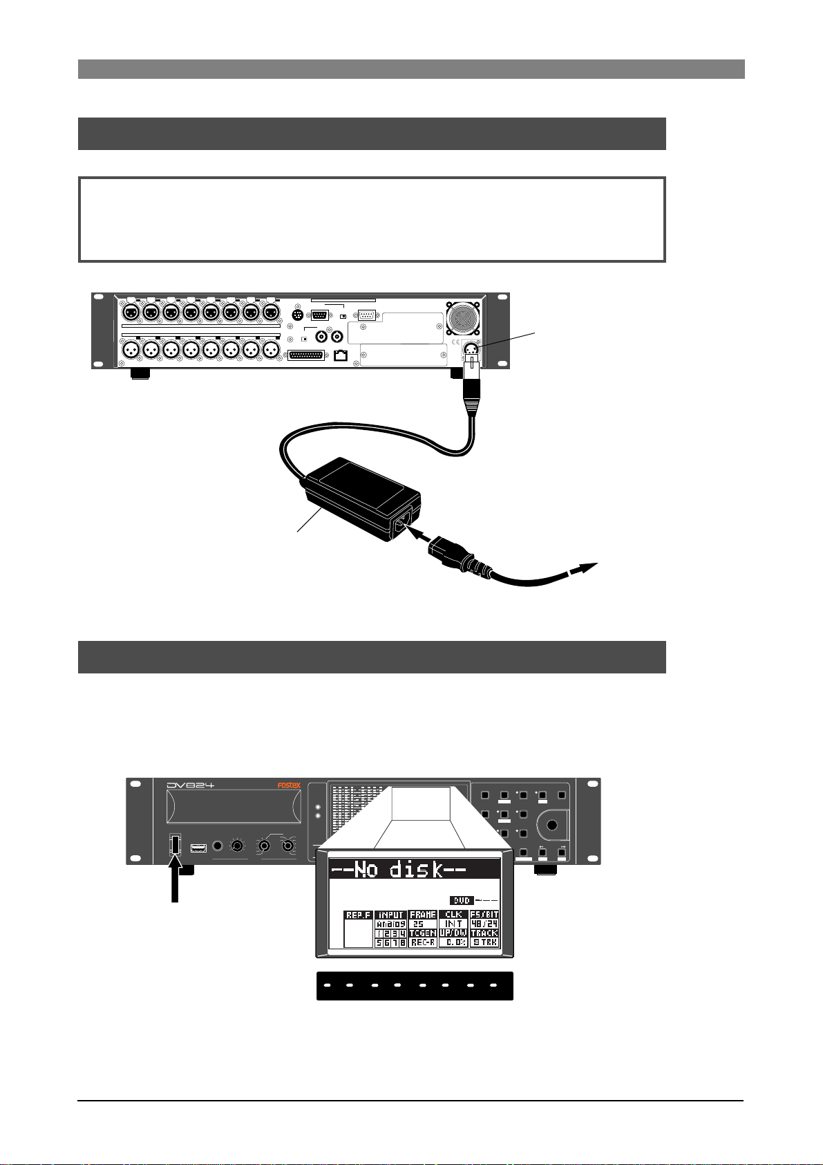
Po wer connection
Connect the supplied AC adaptor as shown below.
<Notes>:
Only use the AC adaptor provided. Using another AC adaptor may cause damage
of the unit due to the mismatch of the power voltage or polarity.
Also make sure that the power of the unit is off when plugging or unplugging the AC
adaptor connector.
PARALLEL
7
8
1:GND 2:HOT 3:COLD
876
6
ANALOG INPUT BALANCED [+4dBu]
ANALOG OUTPUT BALANCED [+4dBu]
543
1
2345
21
REMOTE
DIGITAL I/O AES/EBU
AC adaptor (Model AD-15C)
P2/ES BUSS
INPUT
WORD WORD
INPUT
75Ω
ON
OFF
THRU
100Ω
ON OFF
OUTPUT
ETHERNET
LINKTX/RX
DC-IN 12V
1:GND
2:NC
3:NC
4:12V
[DC IN 12V] connector
AC outlet
Turning on the power
When turning on the power of the unit, the display shows the starting-up screen, and
the unit starts up. If no DVD-RAM disk is set in the DVD-RAM drive of the unit,
"--No disk--" is shown in the file name area on the display, while "--H --M --S --F" is
shown on the time display.
HD
DVD
OPEN/CLOSE
1234
RECORD
0L
0
4
8
12
16
18
20
30
40
60
5678
-dB
ABS 0
STOP/HOME
HMSF
REWINDPLAY
QUICK SET FILE SEL
LTC
1
space
TC IN
SLATE TONE
ABS
4
GHI
GEN
TIME SEL
DF
7
PQRS
CONTRAST
REC END
MARK/CUE
0
symbol
F FWD
HMS F
2
ABC
DRV/PAT
LIST PLAY
5
JKL
EDIT EDL
ALL INPUT SAFE/RDY
TUV 8 WXYZ
LOCATE
EDIT TIME
PRE REC
EXIT/NO
3
DEF
SHIFT
PUSH
MENU/ENTER/YES
CHASE
6
MNO
9
SKIP/CURSOR
CLEAR
FALSE START
+
-
DVD RECORDER
MONO
TR ODD-
EVEN
TR7-8
TR5-6
TR3-4
MIN MAX
USB
POWER
(KYBD ONLY)
TR1-2
PHONES
ACCESS
SOLO
TR2
TR3
TR1
TR4
TR5
TR6
TR7
TR8
[POWER] switch
After starting up as shown above, set the internal clock to the current date/time by
following the procedure described in "Realtime clock setting" on the next page.
16
Page 17
DVD Multitrack Recorder DV824DVD Multitrack Recorder DV824
DVD Multitrack Recorder DV824
DVD Multitrack Recorder DV824DVD Multitrack Recorder DV824
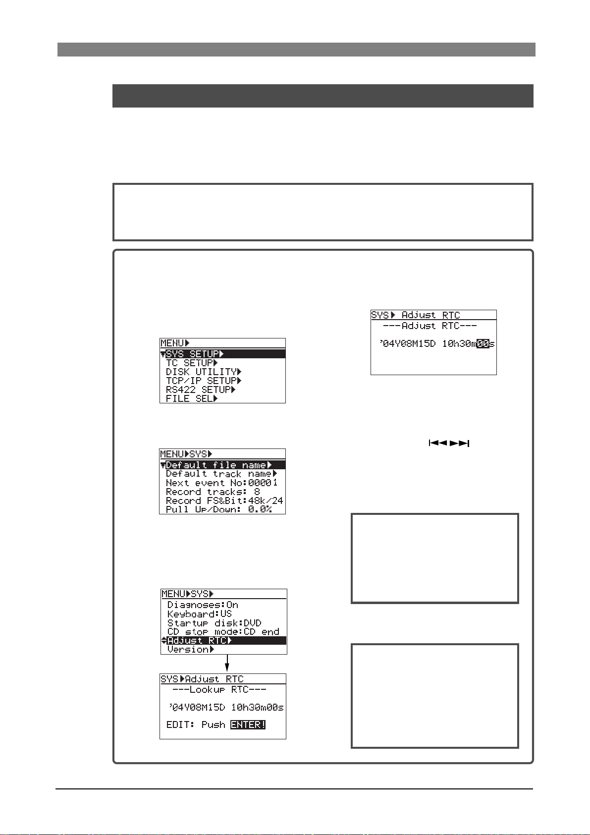
Realtime clock setting
The realtime clock is built in the DV824.
The realtime clock data is used for date/time of creation of a file.
By default, the realtime clock is set according to local date/time of the factory. Therefore, set the clock correctly according to your local date/time before using.
<Note>:
optional TC/SYNC card is installed and the "Gen Mode" item (for TC recording mode setting) of the "TC SETUP" menu in the MENU mode is set to "24H Run" (
details
1) After turning on the power of the unit,
You can record the realtime clock data as the TC start time time only when the
see page 128 for
).
4) Press the [ENTER/YES] key again.
press the [ENTER/YES] key to enter
the MENU mode.
The display now shows the MENU list
screen on which "SYS SETUP" is highlighted.
The clock data at the moment when
pressing the key is hold and the
"second" field flashes.
5) Enter date/time data.
Use the [MENU] dial (or the alphanumeric
2) Press the [ENTER/YES] key again.
The display now shows the "SYS SETUP"
menu.
keys) to enter a desired value to the
current cursor position (flashing field).
You can move the cursor position using
the [SKIP/CURSOR
] keys.
6) After entering date/time data, press the
[ENTER/YES] key .
The clock starts running from the entered
date/time.
3) Use the [MENU] dial to highlight
"Adjust RTC" and press the [ENTER/
YES] key.
The display now shows current clock
data which runs in realtime.
17
<Note>:
time shortly ahead of "now" (such
as one minute ahead) in step 5
above and pressing the [ENTER] key
(in step 6 above) at the moment
when the current time reaches the
entered time.
We recommend entering a
7) Press the [ST OP/HOME] key to exit the
MENU mode.
<Note>:
lithium battery which is used for
driving the realtime clock.
The battery life is approximately
five years. The battery replacement
is done by local Fostex distributor's
service department or their authorized service agent.
The unit has an internal
Page 18
DVD Multitrack Recorder DV824DVD Multitrack Recorder DV824
DVD Multitrack Recorder DV824
DVD Multitrack Recorder DV824DVD Multitrack Recorder DV824
About recommended disks
DVD-RAM disks used with the DV824
4.7GB Type 2 single-sided or 9.4GB Type 4 double-sided DVD-RAM disks can be
used with the unit. When the unit is shipped, a 34.7GB Type 2 single-sided disk is
supplied as standard.
9.4
4.7
SINGLE SIDED
3
GB
TYPE
2
X
DOUBLE SIDED
3
GB
TYPE
4
X
<Note>:
REWRITABLE
PROTECT
PROTECT
Use only DVD-RAM disks recommended by Fostex.
REWRITABLE
For details about handling a disk, see the instructions of the disk.
<Note>:
This unit also can use the optional hard disk drive as a recording/playback
medium, as well as DVD-RAM disks.
By installing the optional hard disk drive, you can not only make recording to a hard
disk partition in realtime, but also make file copy/disk copy between a DVD-RAM disk
and a partition, etc. For details about the optional hard disk drive, contact your local
Fostex distributor.
Advanced operations
See "
" on
pages 83 ~ 91
for details about dual drive recording, file
copy, disk copy, etc. which are possible by installing the optional hard disk drive.
Inserting/removing a disk
After turning on the power, pressing the [OPEN/CLOSE] key opens the disk tray.
After placing a disk on the disk tray, pressing the [OPEN/CLOSE] key again closes the
tray.
<Note>:
When placing a disk on the tray, make sure that the recording side is down.
ACCESS
HD
DVD
1234
OPEN/CLOSE
RECORD
[OPEN/CLOSE] key
0L
0
4
8
12
16
18
20
30
40
60
5678
-dB
When loading the unused disk supplied with
the unit, the disk is scanned and the display
LTC
shows "Unformat!", followed by the second level
TC IN
screen of the "Format" menu item in the "DISK
ABS
GEN
UTILITY" menu of the MENU mode. You can
DF
ABS 0
HMS F
STOP/HOME
F FWD
REWINDPLAY
now execute the "initial formatting" by follow-
REC END
ing the procedure described on page 20.
18
Page 19
DVD Multitrack Recorder DV824DVD Multitrack Recorder DV824
DVD Multitrack Recorder DV824
DVD Multitrack Recorder DV824DVD Multitrack Recorder DV824
The DVD-RAM drive of the unit can load following types of disks. Depending on the type of a
disk loaded, the unit starts up differently as described below. If you set a disk with the type
other than the following types, the unit automatically rejects it and opens the disk tray.
• Unformatted disk
As described earlier, the unit recognizes that the disk is unformatted and shows "Unformat"
on the display, followed by the "Format" menu item of the "DISK UTILITY" menu in the
MENU mode.
• Unused formatted disk
If you set an unused UDF-formatted disk, the unit scans the disk and recognizes that no
BWF files exist on the disk, then starts up while showing "--No files!--" on the Home screen
(see page 21 for details).
• Recorded disk
If you set a DVD-RAM disk on which any audio file is recorded, the earliest recorded audio
file (file number 001) on the disk is loaded normally. For example, if five recorded audio
files (001 through 005) exist on the disk, the unit always starts up at the beginning (ABS 0)
of the "001" file. However, if the "Resume" menu item of the "DISK UTILITY" menu in the
MENU mode is set to "On", the audio file previously loaded before turning off the power
last time is loaded (see page 154 for details).
• CD-DA format audio CD
If you set an audio CD disk of the Red Book format (regardless of whether it is a CD-R/RW
disk or commercially available CD), the unit starts up at the beginning of track 1 (see page
64 for detaols). Only playback is possible with an audio CD.
Note that some copy-protected audio CDs may not be played back.
• ISO9660-formatted CD-ROM, CD-R or CD-RW
If you set an ISO9660-formatted CD-ROM, CD-R or CD-RW disk, you can play back a WAV
file (BWF) on the disk.
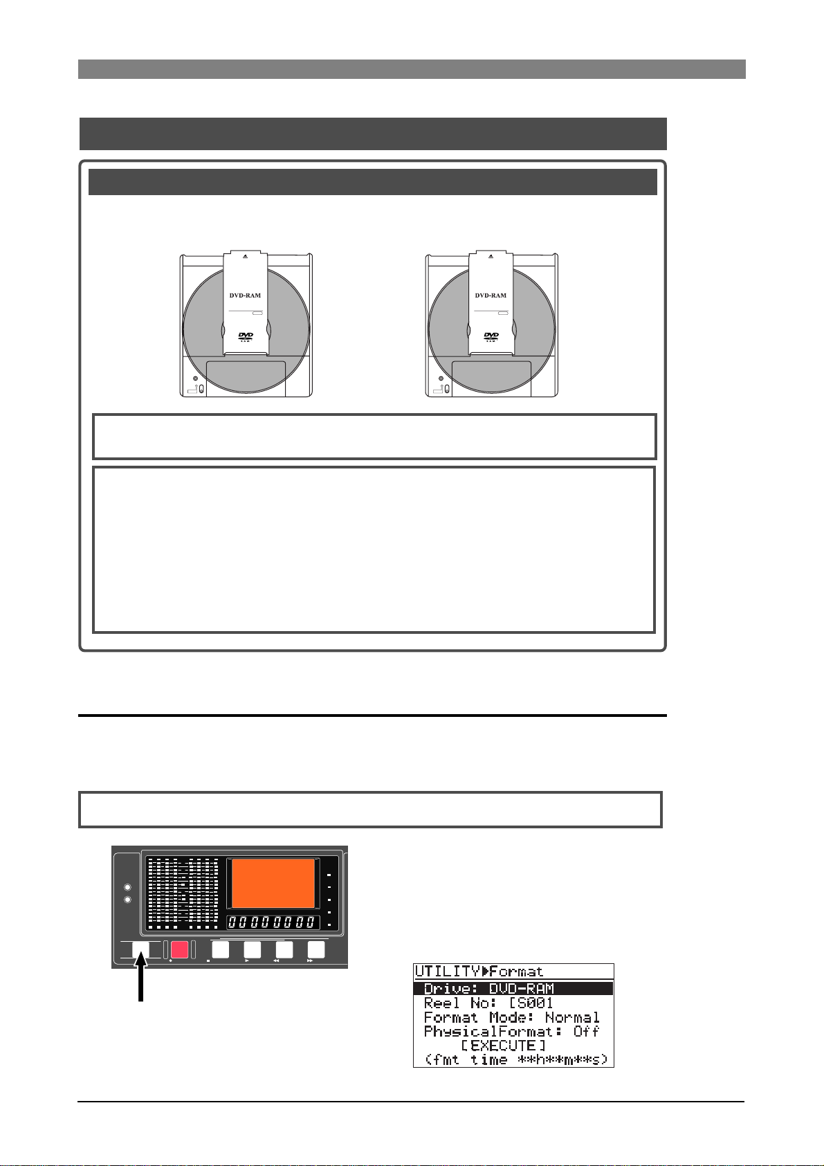
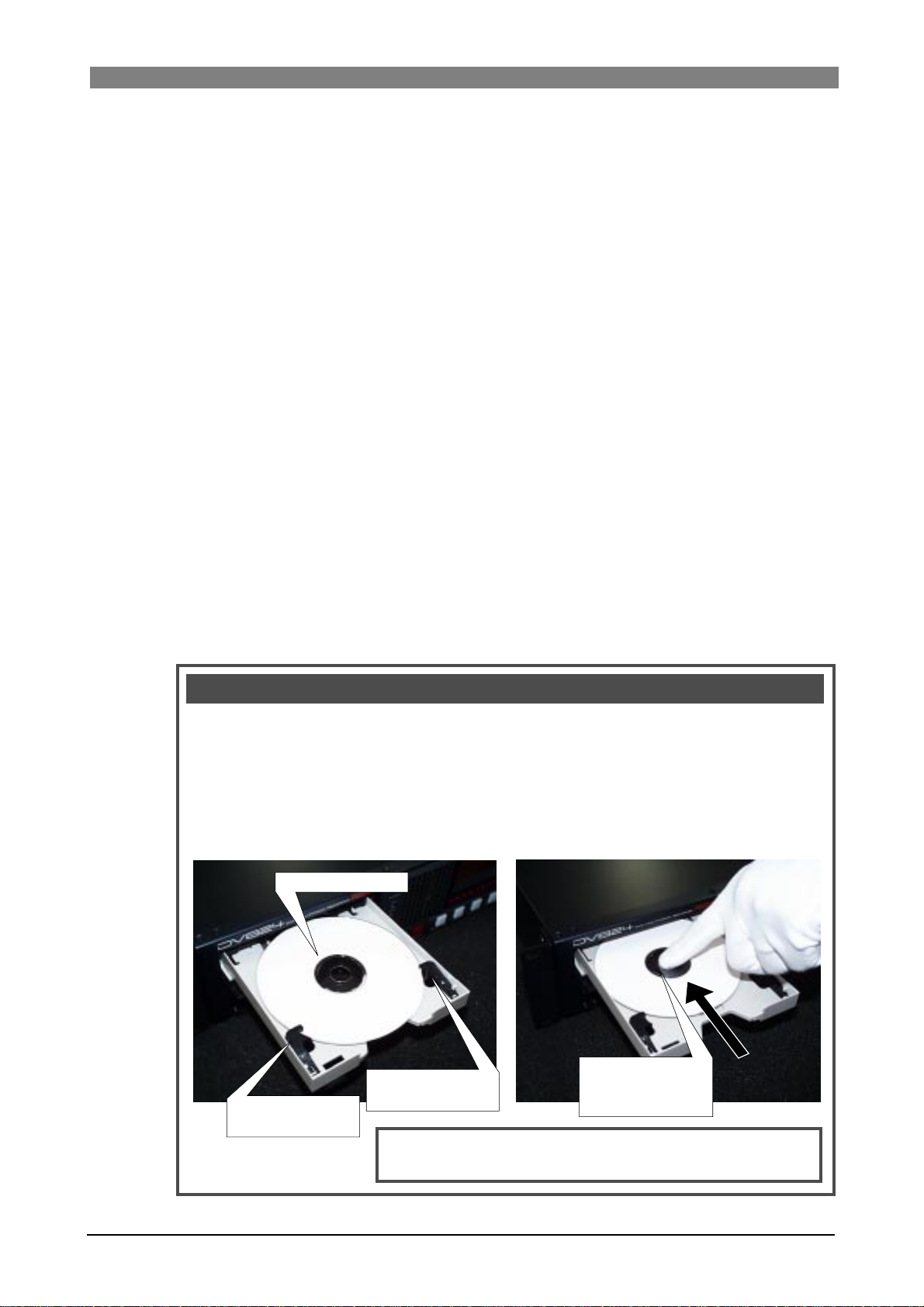
Important notice for setting an uncovered disk to the tray
When you set an uncovered disk (such as a DVD-RAM disk which is taken out from a case,
a CD-ROM or an audio CD), place the disk on the inner position of the tray and then slide
it forward to fix it by the fixing guides on the tray, as shown in <Figure 1>. If you place a
disk on the fixing guides and close the tray, the disk is not loaded correctly, which may
damage the disk or the unit. Please make sure that an uncovered disk is correctly fixed by
the fixing guides before closing the tray. When removing a disk from the tray, slide it
backward and pull it up, as shown in <Figure 2>.
<Figure 1>
Disk
<Figure 2>
The disk must be
fixed by the guide.
The disk must be
fixed by the guide.
<Note>:
disk. An uncovered disk only can be played back.
The unit cannot make recording using an uncovered
To remove a disk,
slide it backward and
pull it up.
19
Page 20
DVD Multitrack Recorder DV824DVD Multitrack Recorder DV824
DVD Multitrack Recorder DV824
DVD Multitrack Recorder DV824DVD Multitrack Recorder DV824
Initial format of a D VD-RAM disk
To make recording/playback by the unit, you have to format a DVD-RAM disk in the
UDF Rev 1.5 format.
When loading an unused DVD-RAM disk, the unit recognizes the disk is not formatted and automatically goes to the second level of the "Format" menu item.
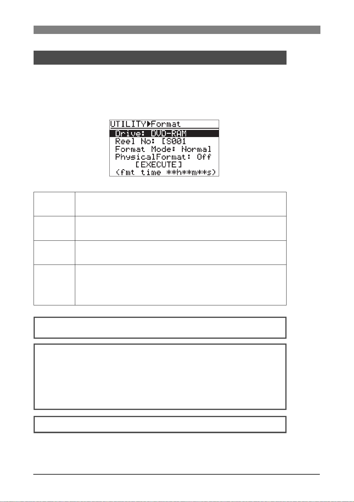
On the "Format" second level screen, you can set the following four items before
executing formatting.
<The "Format" second level screen>
Selects a drive for formatting. If the optional hard disk drive is not installed, the internal
Drive
DVD-RAM drive is the only option. If the optional hard disk drive is installed, you can select
from among hard disk partitions (PT01 through PT08) and the internal DVD-RAM drive.
Reel No
Format Mode
Physical Format
<Note>:
menu. For details about reel number editing, see "Editing the reel number" on page 152.
<Note>:
We also recommend executing the physical format for an unused disk if you have time.
The following shows the appropriate required time for formatting a 4.7GB DVD-RAM disk
(the required time according to the selection of the "Physical Format" item is shown on the
screen).
Sets the reel number of a disk (or a partition of the optional hard disk drive) to be formatted.
Y ou can change the reel number after formatting, therefore, you do not have to change the
default reel number here.
Selects a desired format mode. If the optional hard disk drive is not installed, "Normal" is
the only option. If the optional hard disk drive is installed, you can select "DDR" for dual
drive recording, as well as "Normal".
Selects whether or not physical-formatting a DVD-RAM disk (or a partition of the optional
hard disk drive).
This item is only valid for the "Normal" format mode. When setting this item to "Off", the unit
executes the simple format and it takes very short time. When setting it to "On", it takes
some time for formatting (see below).
A reel number can be edited using the "Reel No" menu item in the "DISK UTILITY"
When formatting a well-used disk, execute the physical format.
When "Physical Format" is set to "Off": approx. 1 min. 30 sec.
When "Physical Format" is set to "On": appro x. 1 hour 30 min.
<Note>:
For details about dual drive recording, see "
20
Advanced operations
" on page 89.
Page 21
DVD Multitrack Recorder DV824DVD Multitrack Recorder DV824
DVD Multitrack Recorder DV824
DVD Multitrack Recorder DV824DVD Multitrack Recorder DV824
The following description shows how to UDF-format an unused 4.7GB/Type2 DVD-
RAM disk which is supplied with the unit, leaving the four items above as their de-
fault settings.
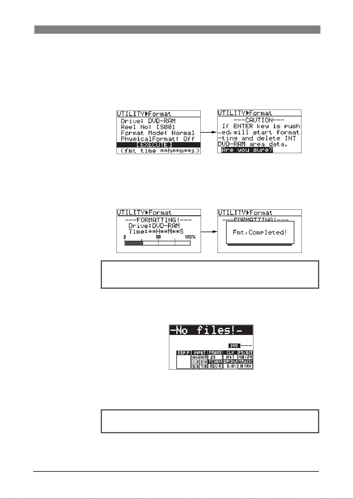
1) Use the [MENU] dial to select "[EXECUTE]" and press the [ENTER/YES] key.
The display changes to show the warning message (i.e. all disk data are gone by
formatting the disk) and flashing "Are you sure?".
2) Press the [ENTER/YES] key again.
The unit starts formatting the disk.
The display shows the formatting countdown, as well as the progress status by the
bar-graph meter.
When formatting completes, the display shows "Fmt. Completed!" and the unit
stops disk access.
<Note>:
approximate information. Do not proceed to the next step before "
pleted!
Note that the formatting countdown and bar-graph meter show the
Fmt. Com-
" is shown.
3) Press the [EXIT/NO] key (or the [STOP/HOME] ke y) to e xit the MENU mode.
The display now shows the Home screen on which "-No files!-" is shown.
Naturally, there is no files on a disk immediately after it is formatted.
Now UDF-formatting of the supplied DVD-RAM disk completed and you can make
recording and playback of the disk.
You can format a DVD-RAM disk you purchase in the same manner as above.
<Note>:
used disk, see "Formatting a disk" on page 149.
To reformat a formatted DVD-RAM disk or to physically format a well-
21
Page 22
DVD Multitrack Recorder DV824DVD Multitrack Recorder DV824
DVD Multitrack Recorder DV824
DVD Multitrack Recorder DV824DVD Multitrack Recorder DV824
Adjusting display contrast
The display contrast of the unit is adjusted suitably when shipped. If you want to
change the contrast, follow the procedure described below.
The following is assumed that the power of the unit is turned on and "--No disk--" is
shown on the display.
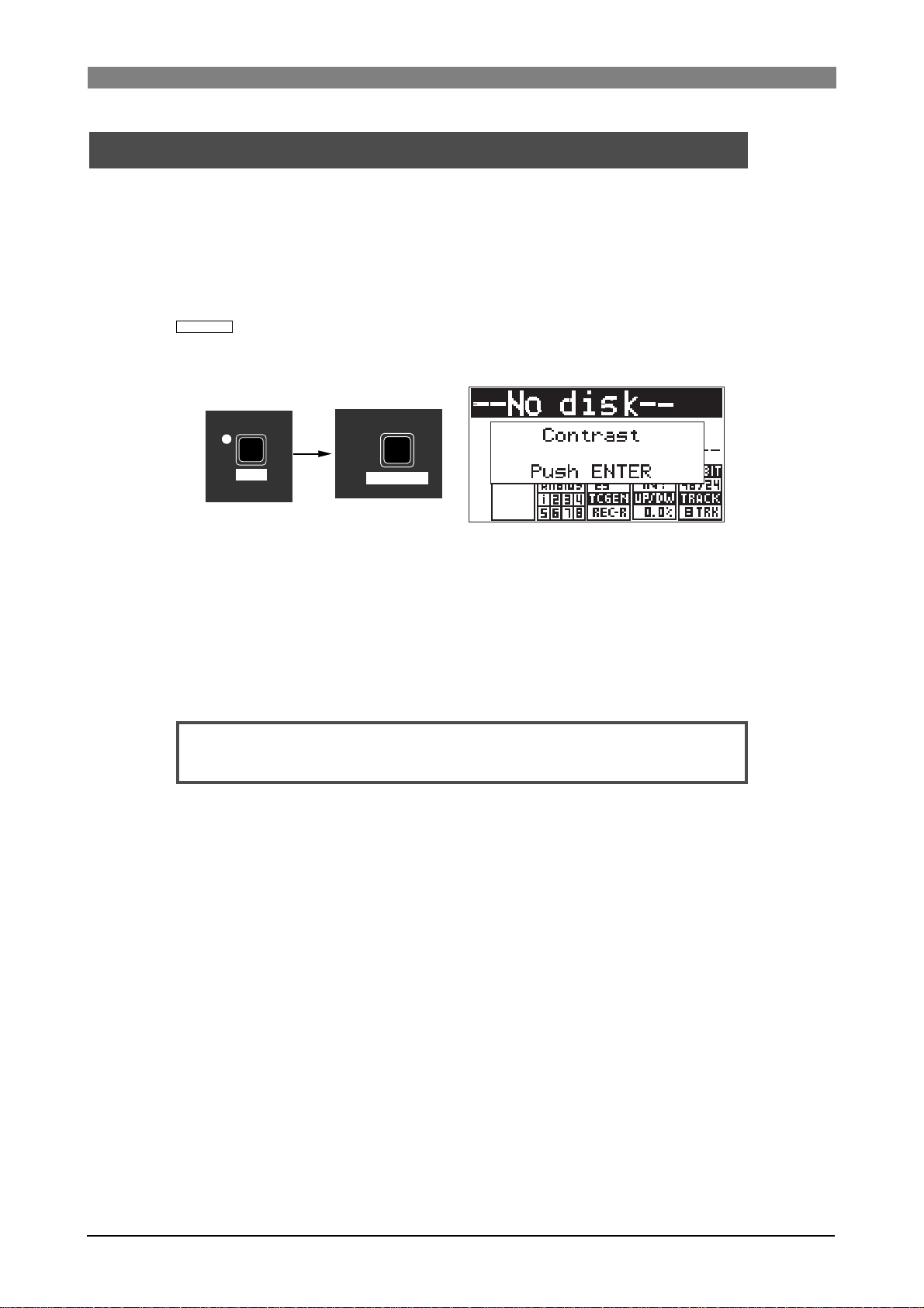
1) Press the [SHIFT] key to turn on the [SHIFT] indicator , f ollo wed by the [TIME SEL/
CONTRAST
The popup message as shown below appears on the display and you can now
adjust the display contrast.
] key.
SHIFT
7
PQRS
TIME SEL
CONTRAST
2) While the popup message above is shown, rotate the [MENU] dial to adjust the
display contrast.
Rotating the dial clockwise weakens the contrast, while rotating it
counterclockwise strengthens the contrast.
3) After adjusting the contrast, press the [ENTER/YES] key to confirm your setting.
The adjusted display contrast is now effective and the popup message above is
dismissed.
<Note>:
[ENTER/YES] key.
The contrast adjustment screen can be dismissed by pressing the
22
Page 23
DVD Multitrack Recorder DV824DVD Multitrack Recorder DV824
DVD Multitrack Recorder DV824
DVD Multitrack Recorder DV824DVD Multitrack Recorder DV824
Chapter-3: Names and functions
Front panel
0L
0
4
8
12
16
18
20
30
40
60
5678
1234
-dB
ABS 0
STOP/HOME
RECORD
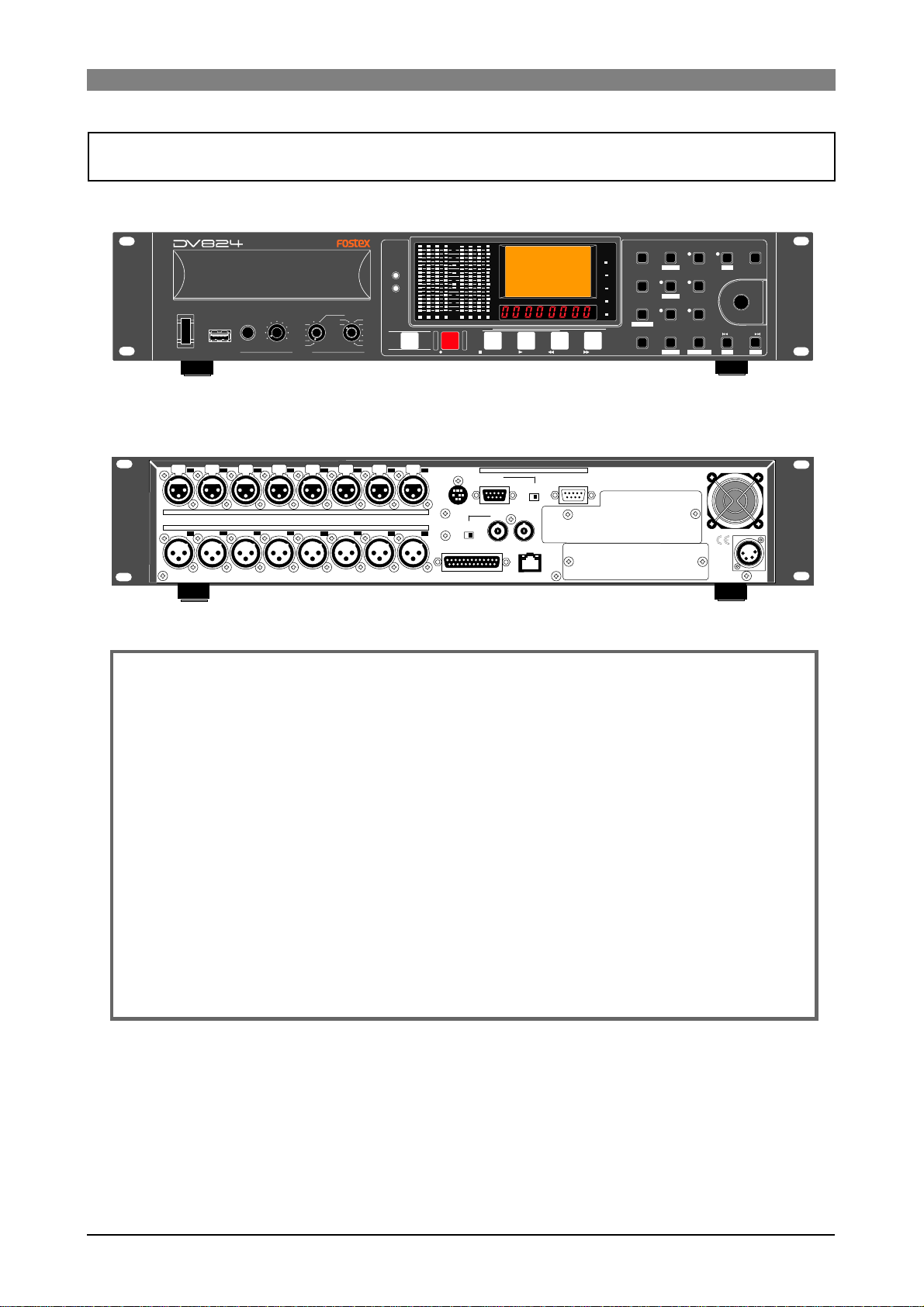
Rear panel
PARALLEL
1
REMOTE
INPUT
WORD WORD
INPUT
75Ω
ON
OFF
DIGITAL I/O
HMSF
F FWD
REWINDPLAY
P2/ES BUSS
THRU
100Ω
ON OFF
OUTPUT
ETHERNET
LINKTX/RX
LTC
TC IN
ABS
GEN
DF
REC END
QUICK SET FILE SEL
1
space
SLATE TONE
4
GHI
TIME SEL
7
PQRS
CONTRAST
MARK/CUE
0
symbol
ABC
TUV 8 WXYZ
USB
POWER
(KYBD ONLY)
7
8
1:GND 2:HOT 3:COLD
876
DVD RECORDER
TR ODD-
MIN MAX
6
ANALOG INPUT BALANCED [+4dBu]
ANALOG OUTPUT BALANCED [+4dBu]
EVEN
TR7-8
TR5-6
TR3-4
TR1-2
PHONES
543
TR4
TR5
TR6
TR7
TR8
SOLO
MONO
TR2
TR3
TR1
ACCESS
HD
DVD
OPEN/CLOSE
2345
21
2
DEF
DRV/PAT
LIST PLAY
5
JKL
MNO
EDIT EDL
ALL INPUT SAFE/RDY
LOCATE
EDIT TIME
PRE REC
3
CHASE
6
9
CLEAR
FALSE START
SHIFT
MENU/ENTER/YES
SKIP/CURSOR
-
1:GND
2:NC
3:NC
4:12V
EXIT/NO
PUSH
+
DC-IN 12V
Table of contents
Front panel ...................................................................................................................................24
Rear panel ....................................................................................................................................30
Display ..........................................................................................................................................33
Home screen ..........................................................................................................33
File name ......................................................................................................33
Next file name .............................................................................................33
Disk remaining ...........................................................................................33
File number .................................................................................................33
File/disk/partition protection .................................................................33
Status information .....................................................................................34
Screen examples .........................................................................................35
7-segment LED time indicator ............................................................................36
23
Page 24
DVD Multitrack Recorder DV824DVD Multitrack Recorder DV824
DVD Multitrack Recorder DV824
DVD Multitrack Recorder DV824DVD Multitrack Recorder DV824
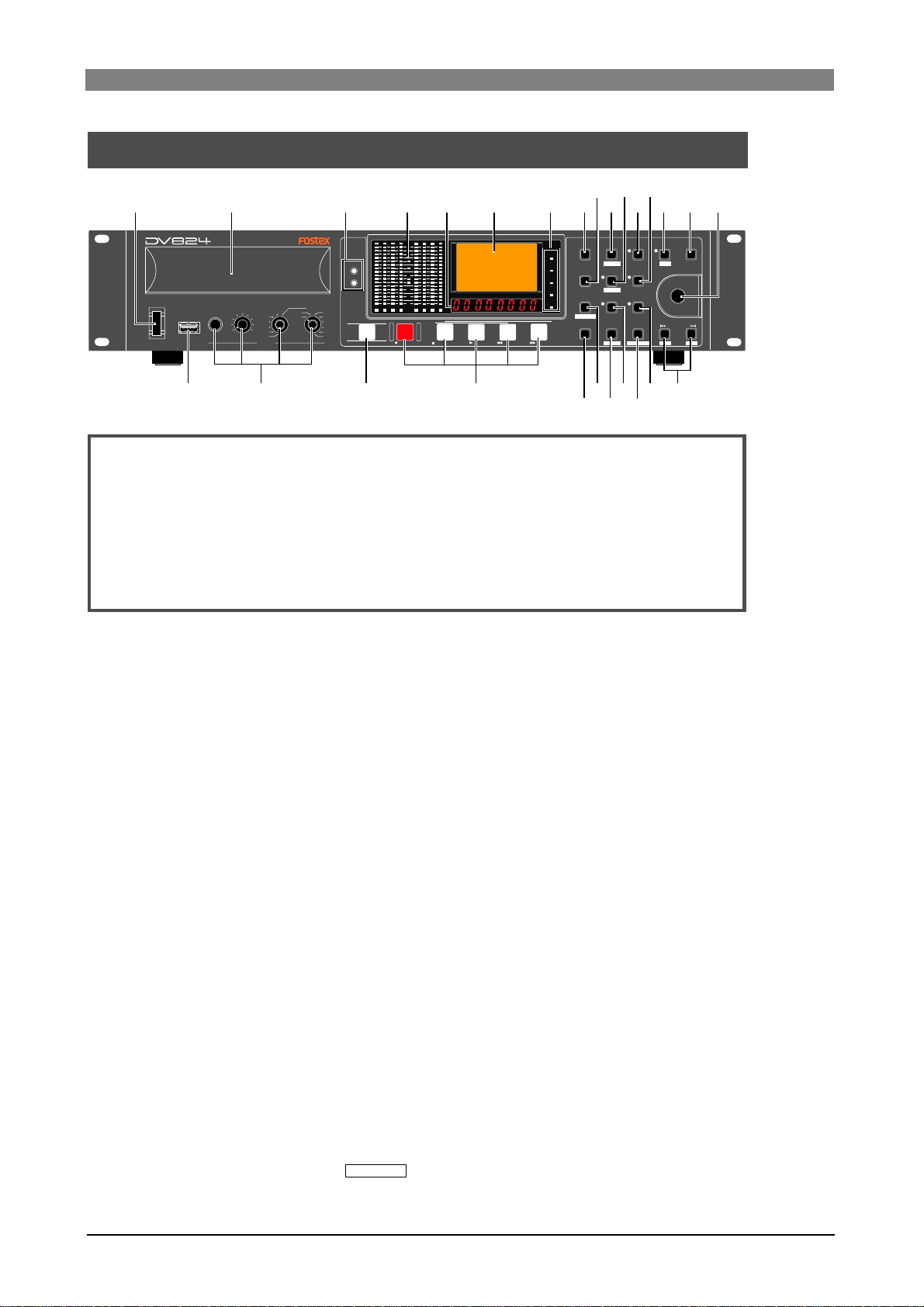
Front panel
1
2
34
5
6
7
9
8
11
10 121314 15 16
1234
RECORD
0L
0
4
8
12
16
18
20
30
40
60
5678
-dB
2
ABC
DRV/PAT
LIST PLAY
5
JKL
EDIT EDL
ALL INPUT SAFE/RDY
TUV 8 WXYZ
LOCATE
EDIT TIME
22
21
20
DEF
MNO
PRE REC
3
CHASE
6
9
CLEAR
FALSE START
19
SHIFT
PUSH
MENU/ENTER/YES
SKIP/CURSOR
-
1718
QUICK SET FILE SEL
LTC
1
space
TC IN
SLATE TONE
ABS
4
GHI
GEN
TIME SEL
DF
ABS 0
HMSF
STOP/HOME
REWINDPLAY
7
PQRS
CONTRAST
REC END
MARK/CUE
0
symbol
F FWD
24
23
POWER
USB
(KYBD ONLY)
DVD RECORDER
MIN MAX
TR ODD-
EVEN
TR7-8
TR5-6
TR3-4
TR1-2
PHONES
ACCESS
HD
DVD
SOLO
MONO
TR2
TR3
TR1
TR4
TR5
TR6
TR7
TR8
OPEN/CLOSE
252627
About Non-shift mode and Shift mode
*Some keys have the secondary function which is available when the SHIFT indicator is lit (i.e. in the Shift mode), while the primary function is available when
the SHIFT indicator is unlit (i.e. in the Non-shift mode).
In this manual, we sometimes say "when SHIFTed" and "when unSHIFTed", instead of "when the SHIFT indicator is lit" (or "in the Shift mode") and "when the
SHIFT indicator is unlit" (or "in the Non-shift mode") respectively.
1) [POWER] s witc h
Turns on or off the power of the unit.
EXIT/NO
+
2) Disk tray
Loads a DVD-RAM disk. Use the [OPEN/CLOSE] key to open or close the tray.
See page 18 for details about DVD-RAM disks which can be used with the unit.
3) [ACCESS] indicator s
Indicates the condition of the current (currently selected) drive.
When the DVD-RAM drive is selected, "DVD" indicator is lit. When any partition
of the optional hard disk drive is selected, "HD" indicator is lit. When the
optional hard disk drive is installed and file copy or disk copy between drives is
being executed, both the indicators are lit.
Depending on the drive condition, the color of the indicator changes as below.
• Lit in green: The drive is selected as the recording medium.
• Lit in orange: Now reading data.
• Lit in red: Now writing data.
4) Level meters
Show the recording/playback level of tracks 1 through 8.
5) 7-segment time display
Shows time data in the currently selected time mode. You can select the time
mode using the [TIME SEL/
CONTRAST
] key (See page 51 for details).
24
Page 25

DVD Multitrack Recorder DV824DVD Multitrack Recorder DV824
DVD Multitrack Recorder DV824
DVD Multitrack Recorder DV824DVD Multitrack Recorder DV824
6) LCD display
Shows audio file information, menu setting screens, etc. (see page 33 for details).
7) Time mode indicators
The indicator of the current time mode is lit.
8) [QUICK SET/1, Space] ke y
Pressing this key enters the quick setup mode. In this mode, you can directly
select the setting items (INPUT, FRAME, CLK, FS/BIT, TC GEN, UP/DW and TRACK)
shown on the Home screen (see page 44 for details).
If SAFE/RDY is set to ON, you can also edit the NEXT file name.
When the display shows a screen for alphanumerical character entry, this key is
used for entering "1" or "Space".
9) [SLATE TONE/4, G, H, I] key
Pressing this key outputs the 1-kHz slate tone at the reference level.
During recording, you can also record the slate tone (see page 55 for details).
When the display shows a screen for alphanumerical character entry, this key is
used for entering "4", "G (g)", "H (h)" or "I (i)".
10) [FILE SEL/2, A, B, C/
This key has primary (unSHIFTed) and secondary (SHIFTed) functions.
When unSHIFT ed:
Pressing this key brings up the "FILE SEL" menu item of the MENU mode.
This menu item allows you to select a desired audio file for playback. Use the
[MENU] dial for selecting a file and press the [ENTER/YES] key to confirm your
setting.
When the display shows a screen for alphanumerical character entry, this key is
used for entering "2", "A (a)", "B (b)" or "C (c)".
When SHIFTed:
Pressing this key brings up the "DRIVE SEL" menu item of the MENU mode.
This menu item allows you to select the recording medium (the DVD-RAM drive
or any partition of the optional hard disk drive). Use the [MENU] dial for
selecting a desired medium and press the [ENTER/YES] key to confirm your
setting.
11) [LIST PLAY/5, J, K, L/
This key has primary (unSHIFTed) and secondary (SHIFTed) functions.
When unSHIFT ed:
Pressing this key turns on or off the List play mode. When turning on the List
play mode, the display shows the screen for selecting the list files. You can also
select the track mode and link mode for the List play (see page 66 for details).
When the display shows a screen for alphanumerical character entry, this key is
used for entering "5", "J (j)", "K (k)" or "L (l)".
DRV/PAT
EDIT EDL
] key
] key
When SHIFTed:
Pressing this key brings up the "EDIT EDL FILE" menu item of the MENU mode.
This menu item allows you to create or edit the ALE file for exporting recorded
audio files to the AVID system (see page 99 for details).
25
Page 26
DVD Multitrack Recorder DV824DVD Multitrack Recorder DV824
DVD Multitrack Recorder DV824
DVD Multitrack Recorder DV824DVD Multitrack Recorder DV824
12) [PRE REC/3, D , E, F] key
Pressing this key turns on or off the Pre rec mode.
While the Pre rec mode is on, the indicator lights and you can starts recording
from the audio data stored in the buffer (see page 54 for details).
When the display shows a screen for alphanumerical character entry, this key is
used for entering "3", "D (d)", "E (e)" or "F (f)".
13) [CHASE/6, M, N, O] key
Pressing this key turns on or off the Chase mode (see page 92 for details). While
the Chase mode is on and the unit is chasing the master, the indicator flashes if
chase-lock is not achieved, or lights if chase-lock is achieved.
When the display shows a screen for alphanumerical character entry, this key is
used for entering "6", "M (m)", "N (n)" or "O (o)".
14) [
Pressing this key turns the shift mode on or on. When on, the indicator is lit and
you can execute a SHIFTed (secondary) function of a key which has dual
functions. The SHIFTed function of a key (if available) is labeled under the key.
SHIFT
] key
15) [EXIT/NO] key
This key has opposite functions to the [ENTER/YES] key.
It is used to cancel editing or execution.
16) [MENU] dial/[ENTER/YES] key
This knob has dual functions; the [MENU] dial for selecting an option and the
[ENTER/YES] key for confirming the selection.
Pressing the [ENTER/YES] key enters the MENU mode. In the MENU mode, you
can use the [MENU] dial to make settings of each menu item of the MENU mode.
The [MENU] dial also can be used for entering alphanumerical characters.
17) [SKIP/CURSOR , ] keys
These keys have primary (unSHIFTed) and secondary (SHIFTed) functions.
When unSHIFT ed:
Depending on "Skip mode" setting of the "SYS SETUP" menu item of the MENU
mode, the keys have different functions.
When the skip mode is set to "File" (by default):
Pressing the [ ] or [ ] key skips to the beginning of the previous or
next audio file (ABS 0). You can skip to the beginning of a desired file by
pressing the key as many time as required.
When the skip mode is set to "Cue":
Pressing the [ ] or [ ] key skips to the previous or next cue point in the
current audio file. You can skip to the desired cue point by pressing the key
as many time as required.
When the display shows a screen for entering alphanumerical characters,
these keys can be used for moving the cursor position.
When SHIFTed:
When the display shows a screen for entering time or numerical value with a
plus or minus sign, the [ ] and [ ] keys can be used for entering a minus
("-") and plus ("+") sign respectively.
26
Page 27

DVD Multitrack Recorder DV824DVD Multitrack Recorder DV824
EDIT TIME
DVD Multitrack Recorder DV824
DVD Multitrack Recorder DV824DVD Multitrack Recorder DV824
18) [SAFE/RD Y/9, W, X, Y, Z] ke y
Pressing this key switches the unit between the “record safe” and “record ready”
modes. When recording status, a new audio file is created and the unit records
an audio signal from the beginning of the file (ABS 0). The indicator flashes in
the record ready mode, while it lights during recording (see page 52 for details).
When the display shows a screen for alphanumerical character entry, this key is
used for entering "9", "W (w)", "X (x)", "Y (y)" or "Z (z)".
19) [CLEAR/
FALSE START
] key
This key has primary (unSHIFTed) and secondary (SHIFTed) functions.
When unSHIFT ed:
Pressing this key clears hold data of the level meters.
When the display shows a screen for alphanumerical character entry, this key
clears whole data.
When SHIFTed:
Pressing this key after making recording cancels the recording. It is useful when
recording has been unsuccessfully made. When the recording is canceled, the
file name is reused and the remaining time returns to the previous value (see
page 54 for details).
20) [ALL INPUT/8, T, U, V] key
Pressing this key turn on or off the “All input monitor” mode. Depending on the
All input monitor status, the indicator is lit (when “on”) or unlit (when “off”).
When the Auto EE mode is on, the All input monitor status automatically switches
between on and off depending on the unit status. You can set the Auto EE mode
on/off via the “Auto EE mode” menu item of the “SYS SETUP” menu in the
MENU mode (see page 121 for details).
When the display shows a screen for alphanumerical character entry, this key is
used for entering "8", "T (t)", "U (u)" or "V (v)".
21) [LOCATE/
] key
This key has primary (unSHIFTed) and secondary (SHIFTed) functions.
When unSHIFT ed:
Pressing this key relocates the recorder to the position previously located (if
the recorder has not located to any position before, it locates to "ABS 0").
When the display shows a screen for selecting a cue point, pressing this key
after selecting a desired cue point locates the recorder to the selected cue point
(see page 61 for details).
When SHIFTed:
Pressing this key brings up the TIME EDIT screen and you can edit the current
time. After then, pressing this key locates the recorder to the edited time
position (see page 61 for details).
22) [TIME SEL/7, P, Q, R, S/
CONTRAST
] key
This key has primary (unSHIFTed) and secondary (SHIFTed) functions.
When unSHIFT ed:
Pressing this key changes the time mode on the display among "ABS", "TC IN",
"GEN" and "LTC" in that order (see page 51 for details).
When the display shows a screen for alphanumerical character entry, this key is
used for entering "7", "P (p)", "Q (q)", "R (r)" or "S (s)".
27
Page 28

DVD Multitrack Recorder DV824DVD Multitrack Recorder DV824
DVD Multitrack Recorder DV824
DVD Multitrack Recorder DV824DVD Multitrack Recorder DV824
When SHIFTed:
Pressing this key enters the contrast adjustment mode and you can adjust the
display contrast (see page 22 for details).
23) [MARK/CUE/0, symbol] ke y
Pressing this key during recording marks a cue on-the-fly (see page 56 for
details).
While the unit is not recording, pressing this key brings up the "CUE LIST"
menu screen and you can edit time data and cue label of a cue point.
When the display shows a screen for alphanumerical character entry, this key is
used for entering "0" or any symbol.
24) Transport control keys
[ PLAY] key
Pressing this key plays back the current drive (DVD-RAM drive or a partition of
the optional hard disk drive).
<Note>:
While the refernce clock (“CLK” item) is set to “DIGI” or “WORD”, if
the FS of the playback file does not match the FS of the unit,
playback is not correctly done. In such a case, make the FS of the
unit match the FS of the playback file.
[ STOP/HOME] key
• Pressing this key stops recording/playback of the current drive.
If you press this key during recording with the Pre rec mode set to "ON", the
unit stops recording after "post recording" is took place.
• If the DVD-RAM drive is selected ad the current drive and the disk tray is
open, pressing this key closes the tray (i.e. acts the same as pressing the
[OPEN/CLOSE] key).
• Pressing this key exits any editing or setting mode and returns to show the
Home screen.
• Pressing the [F FWD] or [REWIND] key while holding down this key locates to
a specific position as below.
[STOP] + [F FWD]: Locates to the last recording position (REC END) of the
current audio file.
[STOP] + [REWIND]: Locates to the beginning (ABS 0) of the current audio
file.
[ REWIND] key
• Pressing this key while stopped starts fast-rewind at up to 30 times the
normal playback speed.
• Pressing this key during playback executes cueing playback.
• While stopped, pressing this key while holding down the [STOP] key locates
to the beginning (ABS 0) of the current audio file.
<Note>:
The maximum cueing speed depends on the FS and the number of
tracks of a file.
[ F FWD] key
• Pressing this key while stopped starts fast-forward at up to 30 times the
normal playback speed.
• Pressing this key during playback executes cueing playback.
28
Page 29

DVD Multitrack Recorder DV824DVD Multitrack Recorder DV824
DVD Multitrack Recorder DV824
DVD Multitrack Recorder DV824DVD Multitrack Recorder DV824
• While stopped, pressing this key while holding down the [STOP] key locates
to the last recording position (REC END) of the current audio file.
<Note>:
The maximum cueing speed depends on the FS and the number of
tracks of a file.
[RECORD] key
• While the [SAFE/READY] indicator is lit, pressing this key automatically
creates a new file and starts recording (see page 52 for details).
If the optional TC/SYNC card is installed, a time code can be striped together
with audio signals, according to the setting of the "Gen Mode" menu item of
the "TC SETUP" menu in the MENU mode (see page 80 for details).
• If the Pre rec mode is set to "ON", pressing this key starts recording from the
audio data stored in the buffer (see page 54 for details).
<Note>:
If record-protection is set to on, pressing this key brings up the
warning message, while the unit does not start recording.
25) [OPEN/CLOSE] key
Pressing this key opens or closes the disk tray.
When a disk is loaded, the unit responds differently depending on the disk, as
described below.
Unused formatted disk:
The display shows "-No files!-".
Recorded disk:
Normally, the recorder locates to the beginning (ABS 0) of "PGM1" (the earliest
recorded audio file on the disk).
Note that, however, if the "Resume" menu item of the "DISC UTILITY" menu in
the MENU mode is set to "ON" and the resume file is correctly set, the recorder
locates to the beginning of the resume file (see page 154 for details).
Unformatted disk:
The unit recognizes that the loaded disk is unformatted and automatically brings
up the "Format" menu item of the "DISC UTILITY" menu in the MENU mode (see
page 20 for details).
26) [PHONES] section
The versatile [PHONES] section allows you to monitor in various combinations
of tracks, including mono mix, stereo mix, stereo pair tracks and a solo track
(see page 51 for details).
27) [USB (KYBD ONLY)] port
This port is used for connecting to a USB keyboard (see page 41 for details).
According to the connected keyboard, set the “keyboard type” menu item in
the “SYS SETUP” menu of the MENU mode appropriately (see page 123 for
details).
VBUS
DD+
GND
1
234
1
2
3
4
29
Page 30
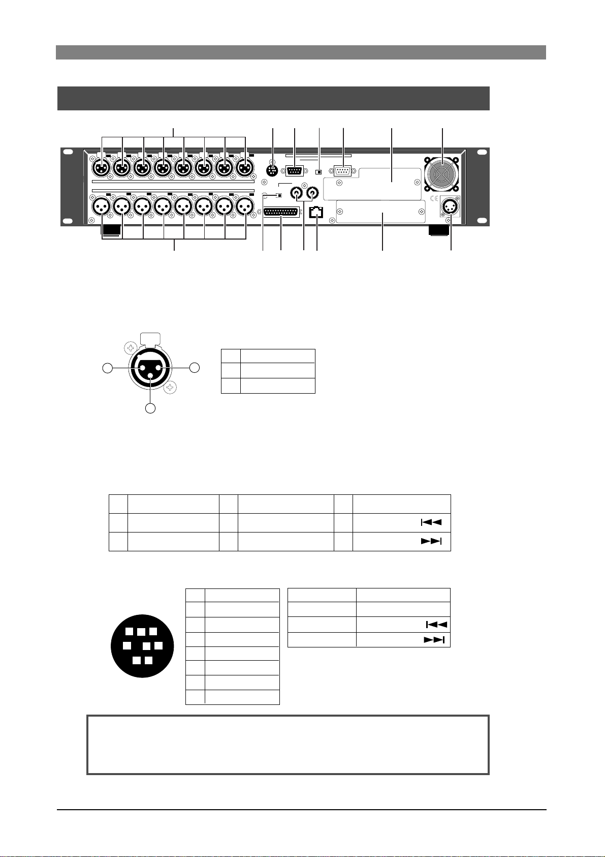
DVD Multitrack Recorder DV824DVD Multitrack Recorder DV824
DVD Multitrack Recorder DV824
DVD Multitrack Recorder DV824DVD Multitrack Recorder DV824
Rear panel
7
8
1:GND 2:HOT 3:COLD
876
1
6
ANALOG INPUT BALANCED [+4dBu]
ANALOG OUTPUT BALANCED [+4dBu]
543
13
2345
21
1
12
2
PARALLEL
REMOTE
75Ω
ON
OFF
DIGITAL I/O AES/EBU
34
P2/ES BUSS
INPUT
100Ω
ON OFF
WORD WORD
INPUT
OUTPUT
ETHERNET
LINKTX/RX
1011
5
THRU
6
69
1) [ANALOG INPUT BALANCED] connectors
These XLR-3-31 type balanced connectors receive analog audio signals for
channels 1 through 8 (+4dBu).
1
3
1
2
3
2
GND
HOT
COLD
1:GND
2:NC
3:NC
4:12V
7
DC-IN 12V
8
2) [PARALLEL REMOTE] connector
This mini DIN 8-pin connector is used for controlling the unit externally.
You can execute the following transport controls/functions remotely via this
connector.
1
2
3
PLAY
STOP
RECORD
REWIND
4
FAST FOR WARD
5
CUE point mark
6
<Pin assignments>
Each transport control/function gets active by grounding the associated pin.
PLA Y
STOP
REC
GND
SHIFT
REW
VBA TT*
FF
8
5
<Note>:
1
2
6
7
4
3
2
1
3
4
5
6
7
8
Pin 7 (DC-12V) derives from the internal main power supply of the unit. If
you short-circuit it to ground or connect it to heavy load, the unit may heat up
abnormally. When using the [PARALLEL REMOTE] connector, connect to lighter load
and never short-circuit the pin.
SHIFT+STOP
SHIFT+REC
SHIFT+REW
SHIFT+FF
(*) VDD (12V), Max 500mA
The power voltage is supplied while the
unit's power is on.
PAUSE
7
SKIP/CURSOR
8
SKIP/CURSOR
9
CUE
PAUSE
SKIP/CURSOR
SKIP/CURSOR
30
Page 31
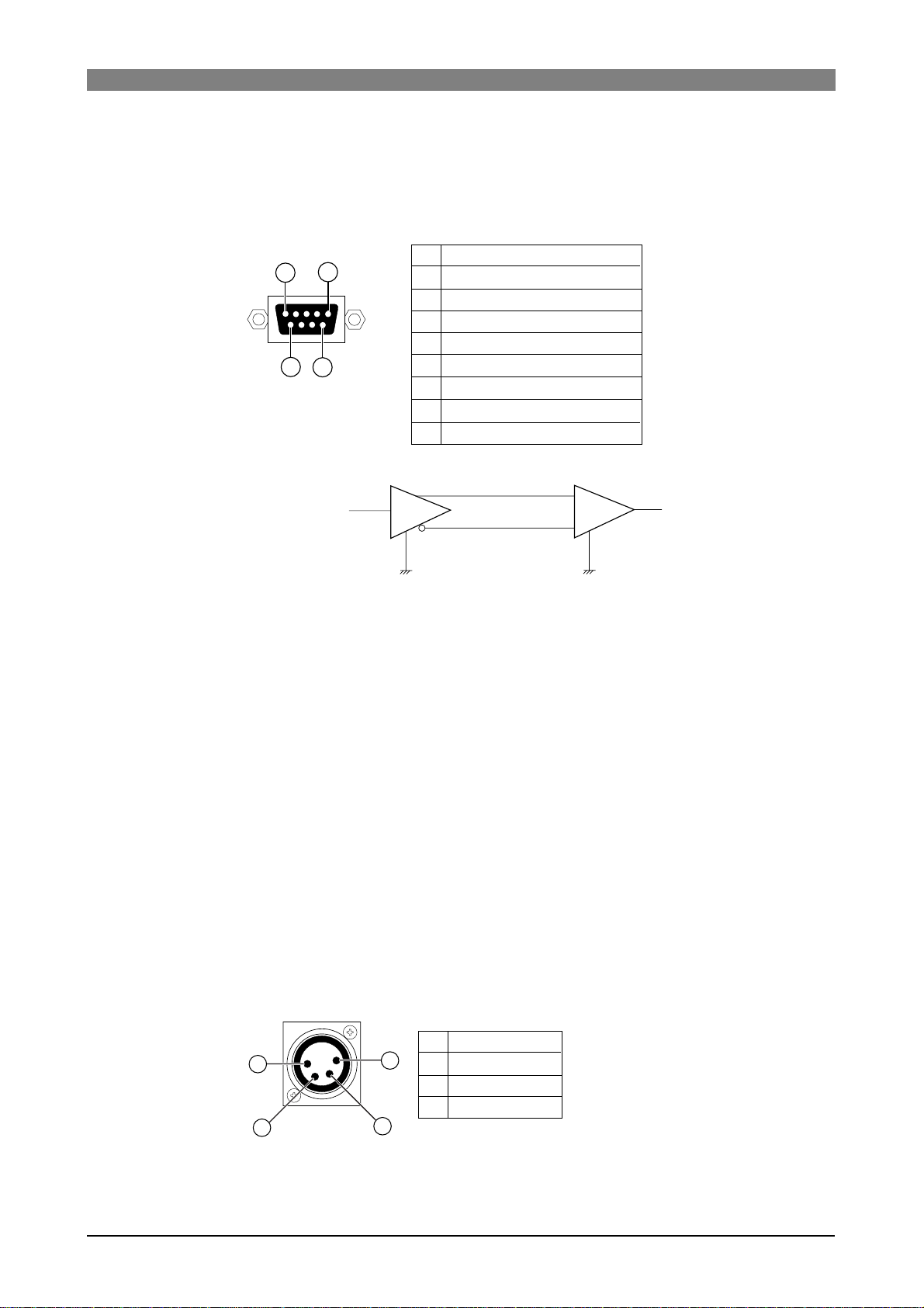
DVD Multitrack Recorder DV824DVD Multitrack Recorder DV824
DVD Multitrack Recorder DV824
DVD Multitrack Recorder DV824DVD Multitrack Recorder DV824
3) [P2/ES BUSS/INPUT] connector
This connector is used for controlling the unit from an external video editor,
etc. The hardware specification is conformed to RS-422A.
The connector type is D-sub 9-pin, female.
Controlled Device
1
1
5
9
6
2
3
4
5
6
7
8
9
*Protocol: conformed to the Sony 9-pin protocol
Frame Ground
Transmit A
Receive B
Receive Common
Spare
Transmit Common
Transmit B
Receive A
Frame Ground
B
T
A
+
R
-
A<B -> "1" (Mark)
B<A -> "0" (Space)
4) Terminate switch (100Ω, ON/OFF)
To terminate the [P2/ES BUSS/INPUT] connector, set this switch to ON.
5) [P2/ES BUSS/THRU] connector
This connector echoes the control signal received at the [P2/ES BUSS INPUT]
connector. See "[P2/ES BUSS INPUT] connector" above for the pin assignment.
The connector type is D-sub 9-pin, female.
6) Blank panels
When installing the optional TC/SYNC card and IEEE1394/USB card, remove
these panels.
7) Cooling fan
This fan ventilates the DV824.
If the ventilation is disturbed, the DV824 may overheat. Therefore, do not block
the vent of the cooling fan.
8) [DC IN 12V] connector
This connector is used to connect to the supplied AC adaptor (Model AD-15C).
The connector type is XLR-4-32.
1
1
4
3
2
2
3
4
GND
NC
NC
12V
31
Page 32

DVD Multitrack Recorder DV824DVD Multitrack Recorder DV824
DVD Multitrack Recorder DV824
DVD Multitrack Recorder DV824DVD Multitrack Recorder DV824
9) [ETHERNET] port
This port is used to connect to the Ether network.
The connector type is RJ45 (conformed to 100/10BASE-T FTP).
The LINK and TX/RX indicators light in the following conditions.
• The LINK indicator lights when the unit recognizes the network.
• The TX/RX indicator flashes when the unit is sending or receiving data.
10) [WORD IN]/[WORD OUT] connector
The [WORD IN] connector receives a word clock signal.
The [WORD OUT] connector feeds word clock signal.
The connector type is BNC.
11) [DIGITAL I/O AES/EBU] connector
This connector inputs and outputs AES/EBU or S/P DIF digital signals.
You can set the digital input channel by the "Setup Digital In" menu item of the
"SYS SETUP" menu in the MENU mode (see page 119 for details).
The unit automatically detects the digital input signal format.
The digital output signal format can be set by the "Digital out" menu item of the
"SYS SETUP" menu in the MENU mode (see page 120 for details).
The connector type is D-sub 25-pin.
Hot
1
2
3
4
5
6
7
8
10, 12, 13, 22, 23
24, 25
9, 11
13
25
14
Signal
1
Input 1/2
Input 3/4
Input 5/6
Input 7/8
Output 1/2
Output 3/4
Output 5/6
Output 7/8
Frame GND
Open
* The connector pin assignment is compatible with the D-sub 25-pin
connectors on YAMAHA equipment.
12) [WORD IN] terminate switch
Terminates the word input signal by setting the switch to “ON”.
Cold
14
15
16
17
18
19
20
21
13) [ANALOG OUTPUT BALANCED] connectors
These connectors output analog audio signals of tracks 1 through 8.
The connector type is XLR-3-32 (balanced/+4dBu).
1
1
3
2
3
GND
HOT
COLD
2
32
Page 33

DVD Multitrack Recorder DV824DVD Multitrack Recorder DV824
DVD Multitrack Recorder DV824
DVD Multitrack Recorder DV824DVD Multitrack Recorder DV824
Display
Home screen
The Home screen is shown after turning on the unit, or during recording or
playback. The screen example below shows the Home screen when a DVD-RAM
disk is set to the DVD-RAM drive.
On the Home screen, various information about the current setting and status
is shown, as described below.
File name
Next file name
Disk remaining
File protection status
Status information
Disk or partition protection status
File number
File name
Shows the name of the audio file currently loaded or being recorded.
If no file exists on the current disk (or partition when optional hard disk drive is installed), "-No Files!-" is shown. If no disk is set to the DVD-RAM drive, "--No disk--" is
shown.
Next file name
Shows the name of the audio file for the next recording. The next file name is shown
only when the [SAFE/RDY] indicator is lit (i,e. the unit is in the rec ready or record
mode). Depending on the setting of the "Default file name" menu item of the "SYS
SETUP" menu in the MENU mode, the name type differs as below.
When "Default file name" is set to "Date"
When "Default file name" is set to "Take"
You can change the next file name via the quick setup mode (see page 49) or the "Default
file name" menu item of the "SYS SETUP" menu (see page 115).
"<DA TE>" is shown.
"Scene + Take number" is shown.
Disk remaining
When the unit is in the rec ready or record mode (i.e. the [SAFE/RDY] indicator is lit),
the disk remaining time is shown. When [SAFE/RDY] indicator is unlit, the volume label
of the current drive is shown.
File number
The file number of the currently loaded audio file is shown in three digits.
If no file exists on the DVD-RAM disk (or the selected partition on the optional hard
disk), "
" is shown.
File/disk/partition protection
If the current audio file or the current disk (or hard disk partition) is protected, the " "
icon is shown. When the current audio file is protected, the " " icon is shown on left
bottom of the status information section.
When the current disk (or partition) is protected, the "
the disk remaining information.
" icon is shown on the right of
33
Page 34
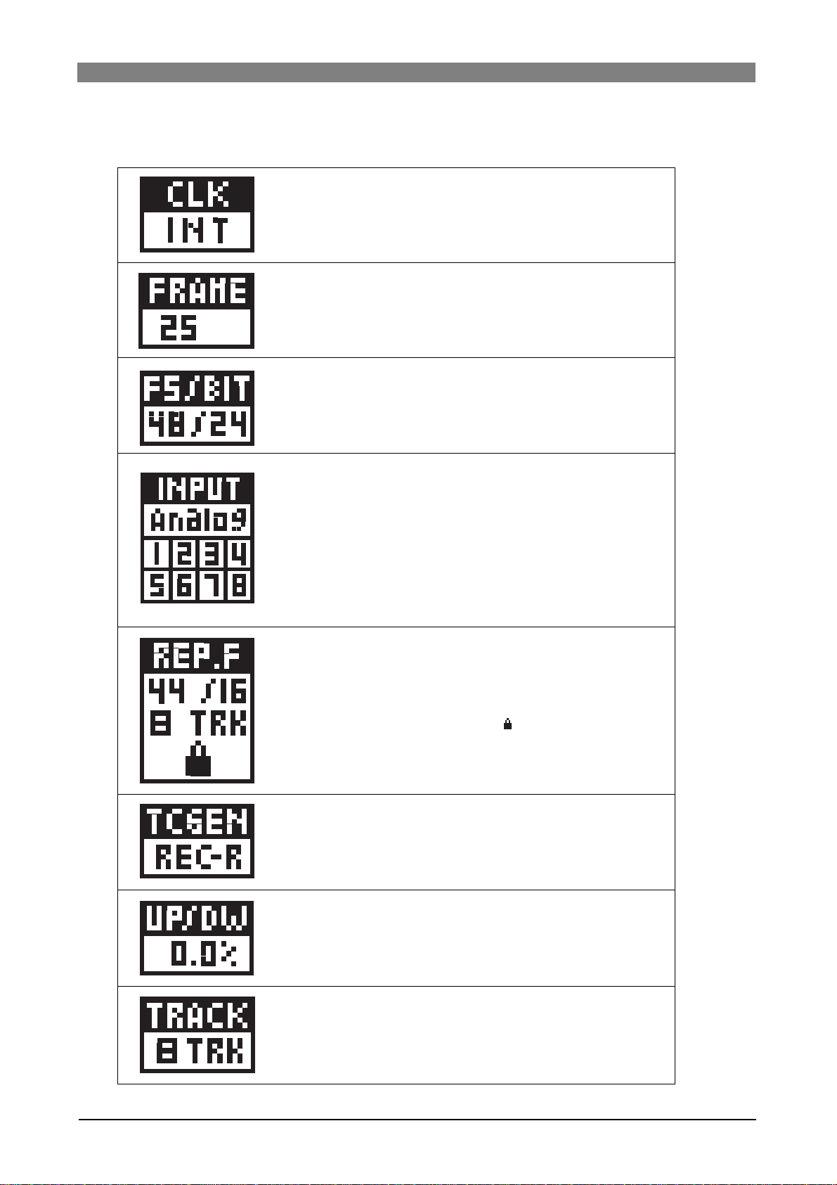
DVD Multitrack Recorder DV824DVD Multitrack Recorder DV824
DVD Multitrack Recorder DV824
DVD Multitrack Recorder DV824DVD Multitrack Recorder DV824
Status information
The current settings of menu items are shown.
The current clock reference setting is shown (the default is "INT").
Y ou can set the clock reference via the quick setup mode (see page 47)
or the "Sync Clock" menu item of the "TC SETUP" menu (see page
127). If the optional TC/SYNC card is installed and the unit does not lock
to the external clock reference, the selected option flashes quickly.
The current time code frame rate setting is shown (the default is "25").
You can set the time code frame rate via the quick setup mode (see
page 46) or the "Frame rate" menu item of the "TC SETUP" menu (see
page 127).
The current FS and bit length setting is shown (the default is "48/24").
You can set the FS and bit length via the quick setup mode (see page
47) or the "Record FS&Bit" menu item of the "SYS SETUP" menu (see
page 117).
The current input mode setting is shown (the default is "Analog").
You can set the input mode via the quick setup mode (see page 45) or
the "Select Input" menu item of the "SYS SETUP" menu (see page 1 19).
If the input mode is set to "DIGIT AL", the currently locked channel(s) (1
through 8) is (are) shown. If no channel is shown even though the input
mode is set to "DIGIT AL", the analog input is selected.
The FS, bit length and track mode of the audio file currently being played
back are shown.
While playing back an audio file, the actual FS, bit length and track
mode of the audio file take priority to the associated menu item settings.
If the current audio file is protected, the "
about how to release the protection, see page 153).
The current time code recording mode is shown (the default is "Run").
You can set the time code recording mode via the quick setup mode
(see page 47) or the "Gen mode" menu item of the "TC SETUP" menu
(see page 128).
" icon is shown (for details
The current pull up/down setting is shown (the default is "0.0%").
You can make the pull up/down setting via the quick setup mode (see
page 48) or the "Pull Up/Down" menu item of the "SYS SETUP" menu
(see page 118).
The current setting of the number of recording tracks is shown (the default is "8 TRK").
You can make the pull up/down setting via the quick setup mode (see
page 48) or the "Record Tracks" menu item of the "SYS SETUP" menu
(see page 117).
34
Page 35

Screen examples
When no disk is set to the DVD-RAM drive
When no disk is set to the DVD-RAM drive, "--No
disk--" is shown in the "File name" area on the Home
screen.
When a formatted unused disk is set to the DVDRAM drive
When formatted unused DVD-RAM disk is loaded,
"-No files!-" is shown in the "File name" area on the
Home screen.
When a recorded disk is set
When a recorded DVD-RAM disk is loaded, a file
name is shown in the "File name" area on the Home
screen.
DVD Multitrack Recorder DV824DVD Multitrack Recorder DV824
DVD Multitrack Recorder DV824
DVD Multitrack Recorder DV824DVD Multitrack Recorder DV824
MENU list screen
The MENU list screen is shown when pressing the
[ENTER/YES] key while the unit is stopped.
This screen is the first level screen of the MENU
mode and you can select a desired menu from 11
menus listed on this screen using the [MENU] dial.
SYS SETUP menu screen
This menu screen is shown when selecting "SYS
SETUP" from the MENU list screen and pressing the
[ENTER/YES] key.
23 menu items are available in the "SYS SETUP"
menu.
DISK UTILITY menu screen
This menu screen is shown when selecting "DISK
UTILITY" from the MENU list screen and pressing
the [ENTER/YES] key.
Twelve menu items regarding disk settings are available in the "DISK UTILITY" menu.
TC SETUP menu screen
This menu screen is shown when selecting "TC
SETUP" from the MENU list screen and pressing the
[ENTER/YES] key.
Sixteen menu items regarding time code recording/
playback, synchronization to an external device, etc.
are available in the "TC SETUP" menu.
35
Page 36

DVD Multitrack Recorder DV824DVD Multitrack Recorder DV824
DVD Multitrack Recorder DV824
DVD Multitrack Recorder DV824DVD Multitrack Recorder DV824
TCP/IP SETUP menu screen
This menu screen is shown when selecting "TCP/IP
SETUP" from the MENU list screen in the MENU mode
and pressing the [ENTER/YES] key.
Six menu items regarding TCP/IP settings for using
the unit in the Ethernet are available in the "TCP/IP
SETUP" menu.
RS422 SETUP menu screen
This menu screen is shown when selecting "RS422
SETUP" from the MENU list screen in the MENU mode
and pressing the [ENTER/YES] key.
Four menu items regarding RS422 settings for controlling the unit from an external editor, etc. are
available in the "TCP/IP SETUP" menu.
EDIT EDL FILE menu screen
This menu screen is shown when selecting "EDIT
EDL FILE" from the MENU list screen in the MENU
mode and pressing the [ENTER/YES] key.
From the EDIT EDL FILE menu, you can create an
ALE file for exporting recorded audio files to the
AVID system.
Popup windows
A popup window appears over the Home screen as
below and shows the current status of the unit. In
the example below, the popup shows that the unit
is now in the display contrast adjustment mode (this
popup can be brought up by pressing the [TIME
SEL] key when SHIFTed).
In this condition, rotating the [MENU] dial controls
the display contrast and pressing the [ENTER/YES]
key confirms the setting.
7-segment LED time indicator
In the 7-segment LED time indicator, the ABS time, LTC (of the internal time
code generator) or external time code is shown in realtime. You can select the
time mode using the [TIME SEL/
HMS F
CONTRAST
] key.
36
Page 37

DVD Multitrack Recorder DV824DVD Multitrack Recorder DV824
DVD Multitrack Recorder DV824
DVD Multitrack Recorder DV824DVD Multitrack Recorder DV824
Chapter-4: Connection
Table of contents
Basic connection ........................................................................................................................38
Analog audio input connection ....................................................................................38
Digital audio input connection .....................................................................................38
External parallel controller connection .......................................................................39
External video editor connection .................................................................................39
Sync signal (word clock) connection ............................................................................39
Ethernet connection .......................................................................................................39
Connection for optional cards ................................................................................................. .40
Time code input/output connection (for the optional TC/SYNC card) .................40
Connection to a film machine (for the optional TC/SYNC card) .............................40
Connection to a personal computer (for the optional IEEE1394/USB card) ..........40
Other connection ........................................................................................................................41
USB keyboard connection ..............................................................................................41
37
Page 38

DVD Multitrack Recorder DV824DVD Multitrack Recorder DV824
DVD Multitrack Recorder DV824
DVD Multitrack Recorder DV824DVD Multitrack Recorder DV824
Basic connection
Analog audio device
6
7
8
1:GND 2:HOT 3:COLD
876
ANALOG INPUT BALANCED [+4dBu]
ANALOG OUTPUT BALANCED [+4dBu]
543
2345
21
Controller
PARALLEL
1
REMOTE
75Ω
ON
OFF
DIGITAL I/O
Video editor
P2/ES BUSS
INPUT
ON OFF
WORD WORD
INPUT
OUTPUT
ETHERNET
Digital audio device
THRU
100Ω
DC-IN 12V
LINKTX/RX
1:GND
2:NC
3:NC
4:12V
Digital audio device
Digital audio device
Personal computer/LAN
Analog audio device
Digital audio device
Analog audio connection
The DV824 provides eight balanced XLR-3-31-type [ANALOG INPUT] connectors which accept
+4 dBu analog audio signals.
The number of recording tracks can be set using the "Record Tracks" menu item of the "SYS
SETUP" menu in the MENU mode (see pages 48 and 117 respectively). The available options are
1 (mono), 2, 4, 5, 6 and 8 (the default is "8").
The DV824 also provides eight balanced XLR-3-32-type [ANALOG OUTPUT] connectors which
output +4 dBu analog audio signals.
Digital audio connection
The DV824 accepts digital signals conformed to IEC 60958 (AES/EBU) or IEC 60958 (S/P DIF)
format (the format of the digital source is automatically detected). The digital connection is
made via the D-sub 25-pin DIGITAL I/O connector.
To record a digital audio source, connect a digital source to the [DIGITAL I/O] connector, and
set the "Select Input" and "Setup digital in" menu items of the "SYS SETUP" menu in the MENU
mode appropriately.
"Select Input" must be set to "Digital" (the default is "Analog"), while "Setup digital in" should
be set appropriately depending on the situation (see pages 45 and 119 respectively). The latter
can be set in pair channels and the default settings of four pairs are all "Digital".
When the DV824 receives a digital source from the selected channels, PLL (Phased-locked
loop) activates and locks to the input sync signal.
The DV824 also outputs digital signals conformed to IEC 60958 (AES/EBU) or IEC 60958 (S/P
DIF) format. The format of the digital output signal can be selected using the "Digital out"
menu item of the "SYS SETUP" menu in the MENU mode (the default is "ABS/EBU"). (See page
120 for details.)
38
Page 39

DVD Multitrack Recorder DV824DVD Multitrack Recorder DV824
DVD Multitrack Recorder DV824
DVD Multitrack Recorder DV824DVD Multitrack Recorder DV824
<Note>:
unit. You can make the FS setting using the "Record FS/BIT" menu item of the "SYS
SETUP" menu in the MENU mode or the quick setup mode (
tively
The FS of the receiving digital input signal must match the FS setting of the
see pages 47 and 117 respec-
).
External parallel controller connection
The DV824 provides the [PARALLEL REMOTE] connector (8-pin mini DIN), which is used for
connecting to an external controller. You can operate the following nine functions using the
external controller.
PLA Y
1
STOP
2
3
RECORD
<Pin assignment>
Each transport control/function gets active by grounding the associated pin.
1
2
8
6
7
4
5
3
2
1
3
4
5
6
7
8
REWIND
4
F. FORWARD
5
CUE point entry
6
PLA Y
STOP
REC
GND
SHIFT
REW
VBATT*
FF
SHIFT+STOP
SHIFT+REC
SHIFT+REW
SHIFT+FF
(*) VDD (12V), Max. 500mA
The power voltage is supplied while the unit's
power is on.
PAUSE
7
SKIP/CURSOR
8
SKIP/CURSOR
9
CUE
PAUSE
SKIP/CURSOR
SKIP/CURSOR
<Note>:
you short-circuit it to ground or connect it to heavy load, the unit may heat up
abnormally. When using the [PARALLEL REMOTE] connector, connect to lighter load
and never short-circuit the pin.
Pin 7 (DC-12V) derives from the internal main power supply of the unit. If
External video editor connection
Using the [P2/ES BUSS INPUT] connector, you can control the DV824 from an external video
editor via RS422. The [P2/ES BUSS THRU] connector allows you to control more than one unit
from the editor (see page 71 for details).
Sync signal (word c loc k) connection
The DV824 provides the [WORD INPUT] connector which is used to lock the DV824 to an
external digital device. The connector accepts a word clock from an external device.
The DV824 also provides the [WORD OUTPUT] connector which feeds a word clock to an
external device.
Ethernet connection
The DV824 is equipped with the ether card and provides the RJ-45 connector which supports
100/10BASE-T FTP.
By connecting the unit to your PC via a LAN cable and setting up the unit as an "FTP (File
Transfer Protocol" server, you can transfer audio files between the unit and PC over TCP/IP.
An appropriate FTP client application is used for file data transfer (see page 73 for details).
39
Page 40

DVD Multitrack Recorder DV824DVD Multitrack Recorder DV824
DVD Multitrack Recorder DV824
DVD Multitrack Recorder DV824DVD Multitrack Recorder DV824
Connection for optional car ds
External time code
TIME CODE
INPUT
OUTPUT
USB
Digital device
DC-IN 12V
1:GND
2:NC
3:NC
4:12V
7
8
1:GND 2:HOT 3:COLD
876
6
ANALOG INPUT BALANCED [+4dBu]
ANALOG OUTPUT BALANCED [+4dBu]
543
1
2345
21
PARALLEL
REMOTE
ON
75Ω
OFF
DIGITAL I/O
Film machine
P2/ES BUSS
INPUT
100Ω
ON OFF
WORD
WORD
INPUT
OUTPUT
LEVEL SEL
24V5V
ETHERNET
LINKTX/RX
THRU
BI-PHASE INPUT
IEEE
1394
Personal computer
Time code input/output connection (for the optional TC/SYNC card)
By installing the optional TC/SYNC card (Model 8348), you can stripe time code generated by
the TC generator on the card or external time code (SMPTE/EBU) received from the [TIME
CODE INPUT] connector, together with audio signals. The [TIME CODE INPUT] connector is
XLR-3-31-type (pin 2=hot).
To stripe external time code, set the "Gen mode" menu item of the "TC SETUP" menu in the
MENU mode or quick setup mode to "Ext Run" (see page 47 and 128 respectively).
While the unit is receiving valid time code via the [TIME CODE INPUT] connector, you can
check the current time and frame rate of the incoming time code by selecting the time mode
on the display to "TC IN". The unit recognizes incoming time code as "valid" when the time
code satisfies the following conditions.
1) The time code runs forward continuously.
2) The sync clock and frame rate of the time code match the DV824 setting.
3) The time code has very few dropouts.
The [TIME CODE OUTPUT] connector outputs SMPTE/EBU time code. The connector is XLR-332 type (pin 2=hot). It can output time code recorded on a disk (REPRO TC) or time code
generated by the time code generator on the optional TC/SYNC card (INT GEN TC), which can
be selected using the "Sel. TC Out" menu item of the "TC SETUP" menu in the MENU mode (see
page 131 for details).
Connection to a film machine (for the optional TC/SYNC card)
The optional TC/SYNC card provides the [BI-PHASE INPUT] connector, which receives a biphase signal for synchronizing the unit to a film machine. To synchronize the unit to a film
machine, set the "BiPhase Setup" menu item of the "TC SETUP" menu in the MENU mode
appropriately (see page 138 for details).
A D-sub, 5-pin type connector with a built-in photo-coupler is used for the [BI-PHASE INPUT]
connector. It accepts a TTL level signal.
Connection to a personal computer (for the optional IEEE1394/USB car d)
By fitting the optional IEEE1394/USB card and installing the driver supplied with the card (or
commercially available DVD writing software application) to your PC, you can transfer audio
files between the DV824 and PC (see page 93 for details).
The IEEE1394/USB card provides a pair of the [IEEE1394] ports conformed to P1394a Draft2.0,
as well as the [USB] port which is "USB Series B Receptacle".
40
Page 41

DVD Multitrack Recorder DV824DVD Multitrack Recorder DV824
DVD Multitrack Recorder DV824
DVD Multitrack Recorder DV824DVD Multitrack Recorder DV824
Other connection
USB keyboard connection
The DV824 provides the [USB] port on the front panel, which is dedicated to a USB keyboard.
By connecting a USB keyboard to this connector, you can enter file and label names, as well as
carry out some of menu operations, from the keyboard.
<Notes>
• To control the DV824 from the USB keyboard, make setting of the "Keyboard Type"
menu item of the "SYS SETUP" menu in the MENU mode appropriately ("US" or
"JAPAN") according to the keyboard connected (
• With some keyboard, indicators may not light until pressing any key after connection is
made.
• We cannot guarantee to work correctly if you use a keyboard with built-in a USB hub,
USB mouse or PS2 mouse.
see page 123 for details
).
USB
POWER
(KYBD ONLY)
USB port
USB keyboard
F1 key
F2 key
F3 key
F4 key
OPEN/CLOSE
F5
&
7
1234
F6
*
8
UY
0L
0
4
8
12
16
18
20
30
40
60
5678
-dB
RECORD
F7
F8
(
9
<
,
ABS 0
STOP/HOME
F10F9
_
)
-+=
0
{
POI
[
LJK
>
?
.
/
Alt
HMSF
F FWD
REWINDPLAY
Print
Screen
F12F11
SysReq
Insert
Back Space
}
|
]
Delete
/
ENTER
SHIFT
Ctrl
Scroll
Lock
Home
LTC
TC IN
ABS
GEN
DF
End
REC END
QUICK SET FILE SEL
1
space
SLATE TONE
4
GHI
TIME SEL
7
PQRS
CONTRAST
MARK/CUE
0
symbol
Pause
Break
Page
Up
Page
Down
2
ABC
DRV/PAT
LIST PLAY
5
JKL
EDIT EDL
ALL INPUT SAFE/RDY
TUV 8 WXYZ
LOCATE
EDIT TIME
Num
/
Lock
89
7
Home
45
2
1
End
0
Ins
MNO
DEF
PRE REC
3
CHASE
6
9
CLEAR
FALSE START
Pg Up
6
3
Pg Dn
.
Del
SHIFT
-
*
+
Enter
DVD RECORDER
MIN MAX
ESC
~
`
TAB
Caps Lock
SHIFT
Ctrl
TR ODD-
TR7-8
TR5-6
TR3-4
TR1-2
!
1
SOLO
MONO
TR2
TR1
EVEN
PHONES
F1
F2
F3
Help
$
@2#
4
3
R
EWQ
ASDF
ZXCV
Alt
ACCESS
HD
DVD
TR3
TR4
TR5
TR6
TR7
TR8
F4
%5^
6
T
GHJ K
BNM
Enters the "Edit file name" menu item of the "DISK UTILITY" menu in the MENU
mode.
Executes the Circle Take function.
Enters the "Default file name" menu item of the "SYS SETUP" menu in the MENU
mode.
Enters the "Default track name" menu item of the "SYS SETUP" menu in the
MENU mode.
PUSH
MENU/ENTER/YES
SKIP/CURSOR
-
EXIT/NO
+
, , , keys
BS key
DEL key
ESC key
ENTER key
Move the cursor or scroll the screen.
Executes "back space" during character entry.
Executes "delete" during character entry.
Acts the same as the [EXIT/NO] key on the panel.
Acts the same as the [ENTER/YES] key on the panel.
HOME key Returns to the Home screen from a screen in the MENU mode.
41
Page 42

DVD Multitrack Recorder DV824DVD Multitrack Recorder DV824
DVD Multitrack Recorder DV824
DVD Multitrack Recorder DV824DVD Multitrack Recorder DV824
AL T key + F key
AL T key + D key
AL T key + C key
AL T key + S key
AL T key + U key
AL T key + Q key
AL T key + E key
AL T key + T key
CTRL key + L key
Acts the same as the [FILE SEL] key on the panel.
Acts the same as the [MARK/CUE] key on the panel.
Enters the "SYS SETUP" menu.
Enters the "DISK UTILITY" menu.
Enters the "Quick setup" mode.
Enters the "EDIT EDL FILE" menu.
Enters the "TC SETUP" menu.
Acts the same as the [LOCA TE] key on the panel.
42
Page 43

DVD Multitrack Recorder DV824DVD Multitrack Recorder DV824
DVD Multitrack Recorder DV824
DVD Multitrack Recorder DV824DVD Multitrack Recorder DV824
Chapter-5: Recor ding/playbac k
Table of contents
Basic audio recording ................................................................................................................44
Setup for recording in quick setup mode ..........................................................44
Entering the quick setup mode ..................................................................45
Input signal selection ..................................................................................45
TC frame rate selection ...............................................................................46
System clock reference selection ...............................................................47
Sampling frequency and bit length selection ..........................................47
TC generator setting ....................................................................................47
Recording track selection ...........................................................................48
Clock pull up/pull down setting ................................................................48
Next file name setting .................................................................................49
Other settings ........................................................................................................50
Reference level setting ................................................................................50
Recording level setting ................................................................................50
Digital input channel setting ......................................................................50
Time display mode selection .....................................................................51
Headphone monitor selection ...................................................................51
Starting recording .................................................................................................52
Canceling recording (False Start) .......................................................................54
Recording in Pre rec mode ..................................................................................54
Recording the slate tone ......................................................................................55
Cue point setting .........................................................................................................................56
Setting a cue point on the fly during audio recording ....................................56
Viewing the cue point list ....................................................................................56
Editing a cue point ................................................................................................57
Editing a cue label ........................................................................................57
Editing cue point data .................................................................................58
Deleting a cue point .....................................................................................58
Adding a new cue point to the cue point list .....................................................58
Basic playback ................................................................................................................ ............59
Normal playback ...................................................................................................59
Cueing playback ...................................................................................................60
Skip/locate functions .................................................................................................................61
Skipping through files ..........................................................................................61
Skipping through cue points ...............................................................................61
Locating to the beginning or end of a file .........................................................61
Locating to the last located point .......................................................................61
Locating to a desired time point .........................................................................62
Locating to a desired cue point ...........................................................................62
43
Page 44
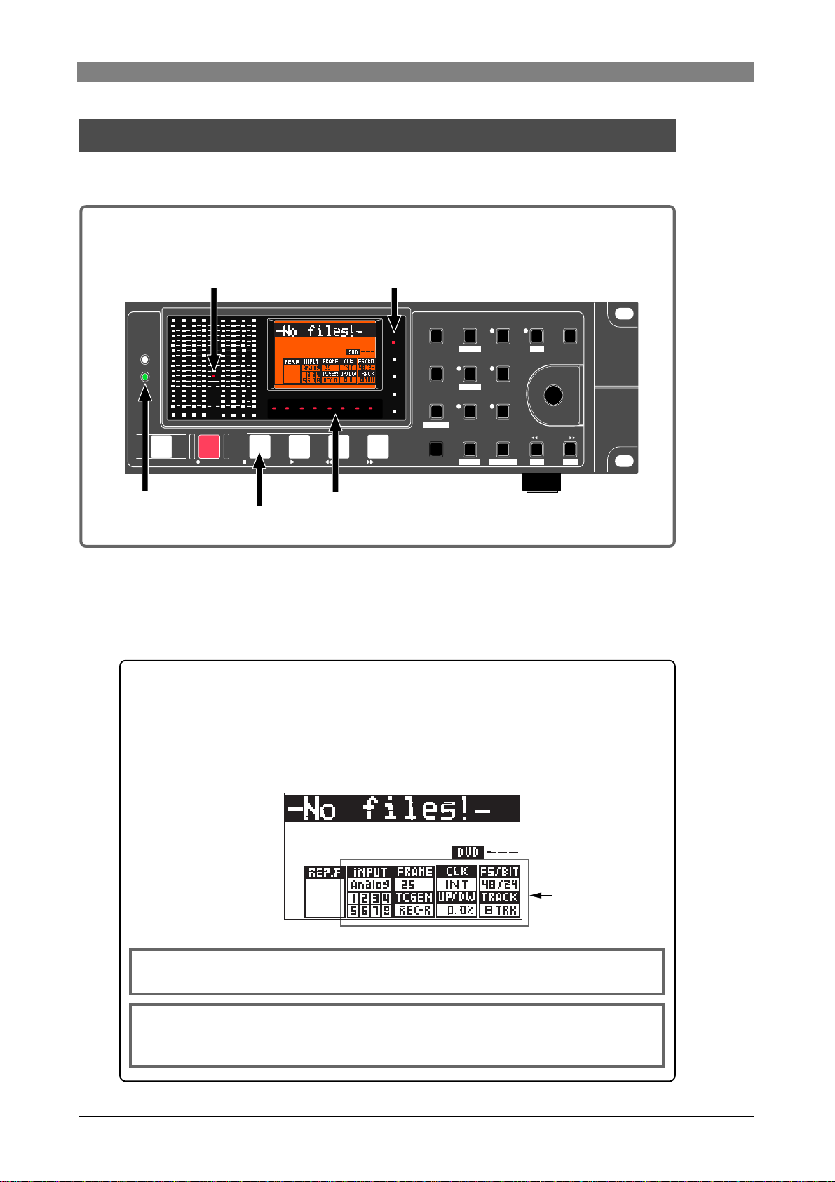
DVD Multitrack Recorder DV824DVD Multitrack Recorder DV824
DVD Multitrack Recorder DV824
DVD Multitrack Recorder DV824DVD Multitrack Recorder DV824
Basic audio recording
Before making basic analog or digital audio recording, you need to make some settings.
If you set a blank disk and start up the unit, "-No files!-" is shown on the display,
while the indicators shown below are lit.
"20" of the reference marker is lit.
0L
0
1234
RECORD
4
16
30
40
60
-dB
ACCESS
HD
DVD
OPEN/CLOSE
[DVD] indicator is lit.
8
12
18
20
5678
ABS 0
HMS F
STOP/HOME
[LTC] indicator is lit.
LTC
TC IN
ABS
GEN
DF
ABS END
symbol
REWINDPLAY
F FWD
“- - H - - M - - S - - F”
QUICK SET FILE SEL
1
ABC
space
SLATE TONE
4
GHI
TIME SEL
7
TUV 8 WXYZ
PQRS
CONTRAST
MARK/CUE
0
PRE REC
2
3
DEF
DRV/PAT
LIST PLAY
5
6
JKL
MNO
EDIT EDL
ALL INPUT SAFE/RDY
9
LOCATE
EDIT TIME
FALSE START
CHASE
CLEAR
SHIFT
PUSH
MENU/ENTER/YES
SKIP/CURSOR
-
EXIT/NO
+
[STOP/HOME] indicator is lit.
Setup for recording in quic k setup mode
Before starting audio recording, you can make necessary settings in the quick
setup mode.
Quick setup mode
In the quick setup mode, you can make basic settings required for recording via the Home screen, while you can make all preferences for the unit via
the appropriate items in the MENU mode.
You can make settings of the items in the status information area pointed
by the arrow below.
<Note>:
"UP/DW" in the status information area can be edited only when the
optional TC/SYNC card is installed.
<Note>:
for details
details
In the quick setup mode, you can also set the next file name (
), as well as set the CD stop mode for audio CD playback (
).
Status information area
see page 49
see page 65 for
44
Page 45

DVD Multitrack Recorder DV824DVD Multitrack Recorder DV824
DVD Multitrack Recorder DV824
DVD Multitrack Recorder DV824DVD Multitrack Recorder DV824
Entering the quick setup mode
You can enter the quick setup mode by following the procedure below.
1) While "-No files!-" is shown on the Home screen, press the [QUICK SET] ke y.
By default, "
In this condition, rotating the [MENU] dial (or pressing the [SKIP/CURSOR
] key) moves the flashing position in the following order.
INPUT
flashing
" in the status information area flashes.
INPUT
TRACK
FRAME
UP/DW
CLK
FS/BIT
TC GEN
2) Select the desired item and press the [ENTER/YES] key.
The current option of the selected item starts flashing and you can now select the
option using the [MENU] dial.
3) Use the [MENU] dial to select the desired option and press the [ENTER/YES] key.
The selected option is set.
4) T o e xit the quic k setup mode, press the [EXET/NO] key (or the [STOP/HOME])
key).
See the following for details about each item.
Input signal selection ("
By selecting "
INPUT
" and pressing the [ENTER/YES] key, you can select the input
" of the status information area)
INPUT
signal between "Analog" (default) and " Digital". You can also make input signal
selection via the "Select Input" item in the "SYS SETUP" menu of the MENU
mode (see page 119 for details), as well as via the quick setup mode.
Analog
You can record analog audio signals fed to the [ANALOG INPUT] connectors.
Y ou can record digital audio signals (AES/EBU or S/P DIF) fed to the [DIGITAL I/0]
Digital
<Note>:
signals from the [DIGITAL I/0] connector on the rear panel or does not lock to
the digital input signals, "Digital" flashes quickly for warning. When the unit
receive correct digital signals and lock to them, "Digital" is steadily lit.
<Note>:
default. However, if you want to record analog and digital signals simultaneously, set the "Setup digital in" menu item in the "SYS SETUP" menu of the
MENU mode appropriately (
between analog and digital in two channel pairs.
connector. The unit automatically detects the digital signal format (AES/EBU or S/
P DIF).
If you select "Digital" but the unit does not receive correct digital
When "Digital" is selected, all channels can record digital signals by
see page 119 for details
). You can select signal source
45
Page 46

DVD Multitrack Recorder DV824DVD Multitrack Recorder DV824
DVD Multitrack Recorder DV824
DVD Multitrack Recorder DV824DVD Multitrack Recorder DV824
<Note>:
The INPUT section in the status information area shows as below de-
pending on the selection between "Analog" and "Digital".
The left screen example shows when “Analog” is selected
here. All channels (1 through 8) can record analog audio
signals, regardless of the “Setup digital in” setting in the
“SYS SETUP” menu.
When selecting
"Analog"
When selecting
"Digital"
When selecting
"Digital"
The left screen example shows when “Digital” is selected
here. All channels (1 through 8) lock to digital input signals and can record them. In this example, the “Setup
digital in” setting in the “SYS SETUP” menu is the default
(i.e. all channels are set to “Digital”).
If a channel does not lock to the digital input signal, it
automatically switches to select analog input, while the
corresponding channel number and “Digital” flash quickly
for warning.
The left screen example shows when “Analog” is selected
here, however, the “Setup digital in” setting in the “SYS
SETUP” menu is as below.
• channels 1-2: “Analog”
• channels 3-4, 5-6 and 7-8: “Digital”
In this case, you can record analog and digital signals
together. If a channel does not lock to the digital input
signal, it automatically switches to select analog input,
while the corresponding channel number and “Digital”
flash quickly for warning.
TC frame rate selection ("
You can select the frame rate of LTC recorded together with audio (or time code recorded when the optional TC/SYNC card is installed).
By selecting "
rate from among the following (the default is "25").
The unit records LTC together with audio signals. By default, "01h00m00s00f" is stamped
at the beginning (one-hour offset to ABS) and the generator records LTC jammed to this
start time code. The LTC recording mode ("TC GEN" mode) is set to "Rec Run" by default, so each time you make audio recording, continuous LTC is recorded.
You can also set the time code frame rate via the "Frame rate" menu item in the "TC
SETUP" menu of the MENU mode (see page 127 for details). You also can edit the LTC start
time via the "Default LTC Start" menu item in the "TC SETUP" menu of the MENU mode
(see page 131 for details).
23.97
24
25
29.97DF
29.97ND
30
30DF
" and pressing the [ENTER/YES] key, you can select the desired frame
FRAME
American motion picture -0.1%
American motion picture
European film/P AL-SECAM video EBU
NTSC color with real time adjust
NTSC color
NTSC video/film
NTSC video/film
" of the status information area)
FRAME
46
Page 47

DVD Multitrack Recorder DV824DVD Multitrack Recorder DV824
DVD Multitrack Recorder DV824
DVD Multitrack Recorder DV824DVD Multitrack Recorder DV824
System clock reference selection ("
You can select the system clock reference.
By selecting "
from among the following (the default is "INT").
To make recording with internal clock reference, select "INT" (default). To make the
unit locked to an external digital or word clock, select "Digital" or "Word". In addition,
you can select "Video" if the optional TC/SYNC card is installed. You can also select the
system clock reference via the "Sync Clock" menu item in the "TC SETUP" menu of the
MENU mode (see page 127 for details).
DIGI
WORD
VIDEO
<Note>:
correct digital (or word) signal or does not lock to the reference signal, "DIGI"
(or "WORD" quickly flashes. In such a case, check cable connection, etc.
<Note>:
played back must match the FS setting of the unit. Otherwise, you cannot play
back the file.
In such a case, make the FS setting of the unit to match the FS of the file.
" and pressing the [ENTER/YES] key, you can select the clock reference
CLK
INT
The unit follows the internal clock.
The unit follows a digital input clock.
The unit follows an external word clock.
Available only when the optional TC/SYNC card is installed. The unit follows
an external video clock.
When "DIGI" (or "WORD") is selected but the unit does not receive a
When the system clock is set to "DIGI" or "WORD", the FS of a file to be
" of the status information area)
CLK
Sampling frequency and bit length selection (“
By selecting "
quency and bit length combination from among the following (the default is "48/24").
You can also select a sampling frequency and bit length combination via the "Record
FS&Bit" menu item in the "SYS SETUP" menu of the MENU mode (see page 117 for details).
Option
22/16
44/16
48/16
44/24
" and pressing the [ENTER/YES] key, you can select a sampling fre-
FS/BIT
FS/BIT
22.05kHz/16bit
44.1kHz/16bit
48kHz/16bit
Option
48/24
88/24
96/24 96kHz/24bit
44.1kHz/24bit
” of the status information area)
FS/BIT
FS/BIT
48kHz/24bit
88.2kHz/24bit
TC generator setting (“ ” of the status information area)
When the optional TC/SYNC card is installed, this item selects the time code recording
mode. When the optional TC/SYNC card is not installed, this item selects the recording
mode of LTC which is always recorded simultaneously with audio signals.
When the optional TC/SYNC card is not installed, by selecting " " and pressing the
[ENTER/YES] key, you can select a desired LTC recording mode between "REC R" and
"EXT" (the default is "REC R"). See the table below for details of these modes. You can
also select the TC generator setting via the "Gen mode" menu item in the "TC SETUP"
menu of the MENU mode (see page 80 and 128 respectively).
The first time you start recording, the generator stamps "01h00m00s00f" as the
REC R
(Rec Run)
LTC start time at the beginning of the file, and records LTC jammed to this start
time code. The next time you start recording, LTC continued from the LTC on the
previous file is recorded.
EXT
(Ext Run)
Every time you start recording, the generator stamps "01h00m00s00f" as the LTC
start time at the beginning of the file, and records LTC jammed to this start time
code. In other words, every file has LTC which starts from "01h00m00s00f".
47
Page 48

DVD Multitrack Recorder DV824DVD Multitrack Recorder DV824
DVD Multitrack Recorder DV824
DVD Multitrack Recorder DV824DVD Multitrack Recorder DV824
<Note>:
The LTC start time is set to "01h00m00s00f" by default. You can edit it
via the "Default LTC start" menu item in the "TC SETUP" menu of the MENU
mode (
see page 131 for details
). For details about the TC generator mode when
the optional TC/SYNC card is installed, see page 77. You can also select a TC
recording mode via the "Gen mode" menu item in the "TC SETUP" menu of the
MENU mode (
Recording track selection (“
By selecting "
TRACK
see page 132 for details
TRACK
).
” of the status information area)
" and pressing the [ENTER/YES] key, you can select the number of
recording tracks from among "1", "2", "4", "6" and "8" (the default is "8".)
You can also select the number of recording tracks via the "Record tracks" menu item in
the "SYS SETUP" menu of the MENU mode (see page 117 for details).
Depending on a DVD-RAM disk, there are some restrictions as shown in the table below.
FS/BIT
22.05kHz/16bit
44.1kHz/16bit
48kHz/16bit
44.1kHz/24bit
48kHz/24bit
88.2kHz/24bit
96kHz/24bit
Recording tracks
Mono
Stereo
Multi (4 track)
Multi (5 track)
Multi (6 track)
Multi (8 track)
Mono
Stereo
Multi (4 track)
Multi (5 track)
Multi (6 track)
Multi (8 track)
Mono
Stereo
Multi (4 track)
Multi (5 track)
Multi (6 track)
Multi (8 track)
4.7GB
Yes
Yes
Yes
Yes
Yes
Yes
Yes
Yes
Yes
Yes
Yes
No
Yes
Yes
No
No
No
No
4.7GB (3x speed)
Yes
Yes
Yes
Yes
Yes
Yes
Yes
Yes
Yes
Yes
Yes
Yes
Yes
Yes
Yes
No
No
No
Recordable time (minutes)
22.05kHz
1,676
838
418
334
279
209
44.1kHz
558
279
139
111
93
69
88.2kHz
279
139
69
44.1kHz
838
419
209
167
140
105
48kHz
513
256
128
102
96kHz
256
128
48kHz
770
385
192
154
128
96
85
64
64
Clock pull up/pull down setting (“
UP/DW
” of the status information area)
When the optional TC/SYNC card is installed, this item allow making the pull up/pull
down setting of the sampling clock/internal TC frame rate if the clock reference is set to
“INT”.
By selecting “
UP/DW
” and pressing the [ENTER/YES] key, you can select from among
“0.0%” (default), “+0.1%” and “-0.1%”.
You can also make the pull up/pull down setting via the “Pull Up/Down” menu item in
the “SYS SETUP” menu of the MENU mode (see page 118 for details).
+0.1%
0.0%
-0.1%
The current FS and internal TC frame rate are pulled up +0.1%.
Normal setting (default).
The current FS and internal TC frame rate are pulled down -0.1%.
48
Page 49

DVD Multitrack Recorder DV824DVD Multitrack Recorder DV824
DVD Multitrack Recorder DV824
DVD Multitrack Recorder DV824DVD Multitrack Recorder DV824
<Note>:
You can make the pull up/down setting only when the clock reference
is set to “INT”. If you select “UP/DW” when any external clock reference (“WORD”,
“VIDEO” or “DIGITAL”) is selected, “Void!” is shown and you cannot make setting.
Next file name setting (“
You can set the next file name while the unit is in the record ready mode (i.e. the [SAFE/
READY] key is set to ON).
When turning on the [SAFE/READY] indicator, the next file name and disk remaining
time are shown on the Home screen. By pressing the [QUICK SET] key in this condition,
you can make settings of items in the status information area. Use the [MENU] dial to
select "
This item defines the name of the audio file created when starting recording next time.
The next file name is set according to the "default file name", which is initially "SCENE
NAME + TAKE No.". In the example above, the next file name is set to "SCENE_001.wav".
NEXT
".
” of the status information area)
NEXT
By selecting "
up the screen for the "Def. file name" menu item in the "SYS SETUP" menu of the MENU
mode.
In this screen, you can edit the default scene name and take number (by default, "S" of
"SCENE" flashes).
You can edit the character at the cursor position using the [MENU] dial (or alphanumeric keys). Up to 18 characters can be entered.
You can move the cursor position using [SKIP/CURSOR ] keys.
Pressing the [CLEAR/
sor position.
After entering the desired scene name, pressing the [ENTER/YES] key confirms your
setting, while the screen prompts you to enter the take number.
Enter the desired take number with the similar manner, and press the [ENTER/YES] key
to confirm your setting.
After completing editing, press the [STOP/HOME] key to exit the MENU mode.
" and pressing the [ENTER/YES] key, the display automatically brings
NEXT
flashing
FALSE START
] key repeatedly clears all the characters behind the cur-
<Note>:
The file name mode for the default file name is set to "Take" by default. You
can set it to "Date" if you want. When setting it to "Date", the realtime clock data is
reflected to a file name. See "Default file name setting" on page 115 for details.
49
Page 50

DVD Multitrack Recorder DV824DVD Multitrack Recorder DV824
DVD Multitrack Recorder DV824
DVD Multitrack Recorder DV824DVD Multitrack Recorder DV824
Other settings
There are some settings besides those made in the quick setup mode.
Reference level setting
The reference level is set to "-20dB" by default. You can change to set this level
to "-18dB" or "-12dB" via the "Ref.level" item in the "SYS SETUP" menu of the
MENU mode (see page 122 for details).
In the level meter section, the associated level indicator with the selected level
is lit.
0L
0
4
8
Lit when "-12dB" is selected.
Lit when "-18dB" is selected.
1234
12
16
18
20
30
60
5678
-dB
Lit when "-20dB" is selected (default).
Recording level setting
The DV824 does not provide a function for adjusting the recording level.
When recording analog audio signals, you should adjust the recording level by
controlling the source output level.
You can check the input level while the [ALL INPUT] indicator is lit.
Before starting recording, you should control the source output level while
checking the level meter and monitoring the source via the headphones.
<Note>:
EE mode" in the "SYS SETUP" menu of the MENU mode to "On", the "ALL INPUT"
mode is always active except during playback (
The "ALL INPUT" mode is off by default. However, by setting the "Auto
see page 121 for details
).
Digital input channel selection
When recording digital audio signals by setting "INPUT" to "Digital" in the quick
setup mode, you can select digital recording channels via the "Setup Digital in"
menu item in the "SYS SETUP" menu of the MENU mode (see page 119 for details).
By default, all channels are set to "Digital" in this menu item. Therefore, unless
you change the "Setup Digital in" setting, you can record digital sources for all
channels simply by setting "INPUT" to "Digital".
<Note>:
mode selects the input channel sources between digital and analog for four channel pairs (channels 1-2, 3-4 and 5-6). For example, if you change the setting for
channels 1-2 to "Analog" , you can record analog sources for channels 1 and 2,
while record digital sources for channels 3 through 8.
The "Setup Digital in" menu item in the "SYS SETUP" menu of the MENU
<Note>:
When recording digital sources, the FS must match between the DV824
and the external device.
50
Page 51

DVD Multitrack Recorder DV824DVD Multitrack Recorder DV824
DVD Multitrack Recorder DV824
DVD Multitrack Recorder DV824DVD Multitrack Recorder DV824
Time display mode selection
The 7-segment time display shows time data in the currently selected time
mode. You can select the time mode between the following using the [TIME SEL/
CONTRAST] key. By default, time data is shown in the "LTC" mode when the
unit is turned on.
LTC
TC IN
ABS
GEN
LTC
TC IN
ABS GEN
HMS F
The time display shows LTC currently being played back or recorded in "h:m:s:f"
format.
When the optional TC/SYNC card is installed, the time display shows external time
code fed to the [TIME CODE INPUT] connector in "h:m:s" format. In the frame field,
the frame rate (24, 29, etc.) of the receiving time code is shown.
When the optional TC/SYNC card is not installed, "--H --M --S --F" is shown.
The time display shows ABS currently being played back or recorded in "h:m:s:f"
format.
When the optional TC/SYNC card is installed, the time display shows time code
generated by the internal TC generator in "h:m:s:f" format only if "Gen mode" is set
to "Free Run" (see page 128 for details about "Gen mode" setting).
<Note>:
When the optional TC/SYNC card is not installed, "--H --M --S
--F" is shown.
Headphone monitor selection
You can select the headphone monitor source using the rotary switches in the
PHONES section.
TR2
TR1
SOLO
TR3
TR4
TR5
TR6
TR7
TR8
SOLO
MONO
TR ODD-EVEN
TR7-8
TR5-6
TR3-4
TR1-2
MONO
TR ODD-
EVEN
TR7-8
TR5-6
MIN MAX
TR3-4
TR1-2
PHONES
Monitors a solo track (1 to 8) selected by the [SOLO] select switch.
Monitors all available tracks in mono.
Monitors all available tracks in stereo (odd tracks to L, even tracks to R).
Monitors tracks 7 and 8.
Monitors tracks 5 and 6.
Monitors tracks 3 and 4.
Monitors tracks 1 and 2.
51
Page 52

DVD Multitrack Recorder DV824DVD Multitrack Recorder DV824
DVD Multitrack Recorder DV824
DVD Multitrack Recorder DV824DVD Multitrack Recorder DV824
Starting recording
After making the necessary settings for recording appropriately, you can start
recording.
The DV824 automatically creates a new audio file (BWF) on the disk each time
you make recording.
In the following description, it is assumed that a formatted blank DVD-RAM
disk is set to the disk tray and the unit is receiving correct analog or digital
audio signals.
1) Press the [SAFE/RDY] key to make the unit record ready.
The [SAFE/READY] indicator starts flashing, while the track indicators of the
recording tracks below the level meters start flashing.
The Home screen changes as below.
SAFE/RDY
9
WXYZ
[SAFE/RDY] key
The Home screen now shows the name of the audio file (New file) created when
recording starts, as well as disk remaining recordable time.
The file name format is set to the "<SCENE NAME> + <TAKE NUMBER>" format by
default. Therefore, the name of the first audio file is "SCENE_001.wav", as shown
above.
<Note>:
The file name automatically set when recording is made is called "default file name". You can change the default file name type to "Creation time/
date.", instead of "<SCENE NAME> + <TAKE NUMBER>" (
). You can also change the file name later (
tails
see page 142 for details
see page 115 for de-
The remaining recordable time varies depending on the FS/bit selection and the
number of recording tracks.
2) Press the [RECORD] key to start recording.
[RECORD] key
ABS 0
OPEN/CLOSE
RECORD
STOP/HOME
REWINDPLAY
When the time mode is set to "LTC", the time display shows LTC starting from
"01H00M00S00F" in realtime. The same time code is recorded to the audio file.
That is, "01h00m00s00f" is stamped at the beginning (ABS 0) and the generator
records LTC jammed to this start time code.
With the default "TC GEN" mode ("REC R"), each time you make audio recording,
the continuous LTC to the previous file is recorded. That is, after the first file, the
first frame of the next file must have the time code of the last frame of the previous file plus one.
When the "TC GEN" mode is set to "EXT", each file starts from the LTC set by the
"Default LTC start" item in the "TC SETUP" menu (the default is "01H00M00S00F").
While the optional TC/SYNC card is installed, the LTC time is recorded if the unit
is receiving external LTC.
You can edit the LTC start time via the "Edit LTC start" menu item in the "TC
SETUP" menu of the MENU mode (see page 132 for details).
REC END
F FWD
).
52
Page 53

DVD Multitrack Recorder DV824DVD Multitrack Recorder DV824
DVD Multitrack Recorder DV824
DVD Multitrack Recorder DV824DVD Multitrack Recorder DV824
3) T o stop recording, press the [STOP/HOME] key.
When recording ends, the Home screen changes as shown below left. By pressing
the [SAFE/RDY] key to exit the record ready mode, the file name and disk
remaining time are dismissed from the Home screen as shown below right.
From the Home screen above left, you can see that the "SCENE_001.wav" audio
file has been created and the next file name is "SCENE_002.wav".
In the "REP.F" field, you can see the FS and bit length of the recorded file.
<Note>:
press the [SAFE/READY] key to exit the record ready mode (i.e. to turn of the
indicator).
If you do not make the next recording after the first recording ends,
4) By pressing the [ REWIND] key while holding down the [STOP/HOME] key,
the unit locates to the beginning of the recorded file ("Locate ABS 0" function).
Pressing the [PLAY] key starts playback of the recorded audio file from the
beginning. See page 59 for details about playback.
<Tip>
If recording was not successful, you can cancel it. See "Canceling recording"
on the next page.
<Tip>
You can also use the "Pre recording" function which prevents missing the start
of a take (see page 54 for details).
<Tip>
During recording, you can set cue points which can be used as markers (see
page 56 for details).
You can also record the slate tone at the beginning of the audio file (see page
55 for details).
53
Page 54

DVD Multitrack Recorder DV824DVD Multitrack Recorder DV824
DVD Multitrack Recorder DV824
DVD Multitrack Recorder DV824DVD Multitrack Recorder DV824
Canceling recording (False Start)
If your recording take is not successfully made, you can cancel the take after
recording and clear the file from the disk by executing the "False start".
<Notes>
• You can cancel only the take most recently recorded, even though you play it
back or switch to another audio file after recording.
Once you cancel the take and clear the file, you cannot restore it anymore.
• If you switch the hard disk partition after recording while the optional hard disk
drive is installed, you cannot execute the False start.
• You cannot execute the False start while the unit is in the "Auto Copy" mode (see
"Auto copy function" on page 83).
1) While the unit is stopped, press the [SHIFT] key to turn on the [SHIFT] indicator
and press the [CLEAR/
The popup message as below appears on the Home screen, asking whether
executing False start or not.
FALSE START
CLEAR
] key.
SHIFT
[SHIFT] key
[CLEAR/FALSE START] key
FALSE START
2) T o cancel the most recent take, press the [ENTER/YES] key.
The display shows "Please wait!", followed by "Completed!", and returns to the
Home screen for the audio file which is recorded before the canceled file.
If you press the [EXIT/NO] key instead of the [ENTER/YES] key above, the display
returns to the Home screen for the most recently recorded audio file.
When canceling the take and clear the audio file, the name of the cleared audio
file is shown in the next file name field and the disk remaining time returns to the
value before the last recording is made.
Recording in Pre rec mode
The DV824 features the "Pre recording" function (in this manual, we say "Pre
rec mode" for the DV824 status when the "Pre recording" function is active).
In the Pre rec mode, recording is made from the audio pooled in the buffer.
This prevents missing the start of a take. For example, if you press the [RECORD]
key a few seconds after an important interview starts, there is no problem.
Because the beginning part of the interview recorded in the buffer also can be
recorded to the disk.
By default, pre recording time of the buffer is set to ten seconds. Via the "Pre rec
time" menu item in the "SYS SETUP" menu of the MENU mode, you can set the
pre recording time to the desired time between one and ten seconds in one
second steps (see page 120 for details).
PRE REC
3
DEF
[PRE REC] key
You can select On/Off of the Pre rec mode using the [PRE REC] key.
When it is set to On, the [PRE REC] indicator is lit. When Off, it is unlit.
54
Page 55

DVD Multitrack Recorder DV824DVD Multitrack Recorder DV824
DVD Multitrack Recorder DV824
DVD Multitrack Recorder DV824DVD Multitrack Recorder DV824
<Note>:
If you execute pre recording at 88.2k or 96k FS, the pre recording time
automatically reduces to half the selected value. For example, if the pre recording
time is set to ten seconds, the buffer stores only five seconds of audio data.
<Tip>
When you stop recording in the Pre rec mode, the unit will stop after executing "post
recording" which records audio data currently stored in the buffer.
<Note>:
In the Pre rec mode, if you switch the Fs/Bit setting, wait for ten seconds
before starting recording .
Otherwise, the audio signal stored in the buffer is recorded with altered pitch.
Recording the slate tone
The DV824 can generate and record the slate tone.
While holding down the [SLATE TONE] key, the slate tone (at 1 kHz, reference
level) is fed to all channels, as well as output from the [ANALOG OUT]
connectors.
You can record the slate tone to the beginning of an audio file during recording,
as well as match the level between the DV824 and an external device.
0L
0
4
Level meters for all channels show the slate tone
level.
1234
8
12
16
18
20
30
40
60
5678
-dB
SLATE TONE
4
GHI
[SLATE T ONE] key
<Tip>
You can clear the peak hold of the level meters by pressing the [CLEAR/
key. You can set the peak hold time of the level meter via the "Peak hold" menu item
in the "SYS SETUP" menu of the MENU mode (by default, three seconds). See page
122 for details.
FALSE START
<Tip>
In the "SYS SETUP" menu of the MENU mode, the "Tone Rec mode" menu item is
available. This item selects the mode for slate tone recording. By default, it is set to
"Off" and the tone is not automatically recorded. Use this menu item when you
want to use the slate tone function (see page 121 for details).
]
<Note>:
When the Pre rec mode is active, the slate tone is not recorded at the
beginning of recording even though the slate tone Rec On/Off is set to "On". The
pop tone can be recorded at the recording end.
55
Page 56

DVD Multitrack Recorder DV824DVD Multitrack Recorder DV824
DVD Multitrack Recorder DV824
DVD Multitrack Recorder DV824DVD Multitrack Recorder DV824
Cue point setting
The DV824 provides the following two ways of setting a cue point.
1. During audio recording, you can set a cue point "on-the-fly" at the desired point.
2. During playback or while stopped, you can set a cue point using the cue point list
on the screen.
Setting a cue point on the fly during audio recording
You can set a "cue point" at the point you press the [MARK/CUE] key during
recording. Up to 99 cue points can be set.
ACCESS
HD
DVD
OPEN/CLOSE
1234
RECORD
0L
0
4
8
12
16
18
20
30
40
60
5678
-dB
ABS 0
HMS F
STOP/HOME
QUICK SET FILE SEL
LTC
1
space
TC IN
SLATE TONE
ABS
4
GHI
GEN
TIME SEL
DF
7
PQRS
CONTRAST
REC END
MARK/CUE
0
symbol
F FWD
REWINDPLAY
2
ABC
DEF
DRV/PAT
LIST PLAY
5
JKL
MNO
EDIT EDL
ALL INPUT SAFE/RDY
TUV 8 WXYZ
LOCATE
EDIT TIME
PRE REC
3
CHASE
6
9
CLEAR
FALSE START
SHIFT
PUSH
MENU/ENTER/YES
SKIP/CURSOR
-
EXIT/NO
+
[MARK/CUE] key
If you press the [MARK/CUE] key during recording, a cue point holding the
current time value is set, while "Cue:**Stored!" (** is a cue number) and the cue
time value are briefly shown on the screen.
Setting a cue point repeatedly counts up the cue number.
You can view cue points after recording.
Viewing the cue point list
Pressing the [MARK/CUE] key while the unit is stopped brings up the CUE LIST
screen as shown below. In this screen, the existing cue points are listed. In the
screen example below, cue points 01 through 04 are set, while no data is stored
on and after cue point 05. The time data is shown by the format based on the
time display indicator).
Labels are automatically given to the recorded CUEs. "BC$START" to CUE 01,
"BC$END" to CUE 02, and "Cue 03", "Cue 04"...."Cue 99" to CUE 03 and the
following cues. "BC$START" and "BC$END" for CUE 01 and CUE 02 are used as
the start and end points which specify the playback range for list play (see "List
play function" described later). Therefore, you can change the playback range
for list play by editing the "BC$ST ART" and/or "BC$END" point(s). See "Editing
a cue point" on the next page for details.
(*) "BC$ST AR T" and "BC$END" are the label names reserved by the BWF-J specification.
56
Page 57

DVD Multitrack Recorder DV824DVD Multitrack Recorder DV824
DVD Multitrack Recorder DV824
DVD Multitrack Recorder DV824DVD Multitrack Recorder DV824
On this list screen, you can not only view cue points but also locate to a cue
point, edit a cue point and add a new cue point to the list.
Editing a cue point
By selecting a desired cue point in the CUE LIST screen, you can edit its label or
point (time data) or delete it.
By highlighting a desired cue point and press the [ENTER/YES] key, the display
changes to show the screen for editing the selected cue point (by default,
"Label" flashes on the screen).
flashing
Editing a cue label
To edit a cue point label, press the [ENTER/YES] key while "Label" flashes.
The first character of the current label flashes, showing that you can now edit it. Use the
[MENU] dial (or alphanumeric keys) to edit the label. After editing the label, press the
[ENTER/YES] key ("Label" starts flashing again).
flashing
<Notes for editing a label>
When using the alphanumeric keys for entering characters, pressing any other alphanumeric key moves the cursor to the right automatically.
You can move the cursor position using the [SKIP/CURSOR ] keys. Pressing
the [CLEAR/
delete the whole label, press the [CLEAR/
character flashes.
FALSE START
] key clears the right next character to the cursor position. To
FALSE START
] key repeatedly when the first
<Note>
By labeling "
can change the playback range for list play (see "List play function" described later).
In the example shown below, the labels for CUE 02 and CUE 04 are edited to "Cue
02" and "
"Song_Link" mode, this file is played back within the range between "CUE 01" (00h
22m 34s) and "CUE 04" (01h 40m 11s).
If you want to play back all data of this file during list play, delete the cues labeled
"
BC$ST AR T
BC$START
BC$END
" and "
" and/or "
" respectively. After edited, if you execute list play in the
BC$END
" or edit "
BC$END
BC$START
" to any other desired cue point(s), you
" and "
BC$END
" to other labels.
Before editing
After edited
57
Page 58

DVD Multitrack Recorder DV824DVD Multitrack Recorder DV824
DVD Multitrack Recorder DV824
DVD Multitrack Recorder DV824DVD Multitrack Recorder DV824
Editing cue point data
To edit cue point data, use the [MENU] dial to select "Position" while "Label" is flashing
and press the [ENTER/YES] key.
The subframe value of the current time data flashes, showing that you can now edit it.
Select the edit point using the [SKIP/CURSOR ] key, edit the value using the
[MENU] dial, and confirm the setting by pressing the [ENTER/YES] key (the display
returns to the CUE LIST screen).
flashing
<Note>:
the time data to "00h00m00s00f".
Regardless of the cursor position, pressing the [CLEAR/
FALSE START
] key resets
Deleting a cue point
To delete an unnecessary cue point, select "Delete" using the [MENU] dial and press the
[ENTER/YES] key ("Sure?" flashes).
Press the [ENTER/YES] key again to delete the cue point from the list.
The display returns to the Home screen.
flashing
<Note>:
while the time value column shows "--h--m--s--f--".
After deleting a cue point, the label column of the cue point becomes empty
Adding a new cue point to the cue point list
While the CUE LIST screen is shown, you can add a new cue point to the list.
Select a desired cue number which does not hold data.
By pressing the [ENTER/YES] key, time data of the current recorder position is
set as the cue point.
In the example below, Cue 05 is set when the current recorder position is "01h
58m 20s **f ** sf" (LTC time).
58
Page 59

Normal playback
DVD Multitrack Recorder DV824DVD Multitrack Recorder DV824
DVD Multitrack Recorder DV824
DVD Multitrack Recorder DV824DVD Multitrack Recorder DV824
Basic playbac k
<Note>:
Using the list play function, you can link multiple audio files which have the same
number of tracks and FS, and play them back continuously.
See "List play function" in "Advanced operations" on page 66 for details.
<Note>:
played back must match the FS setting of the unit. Otherwise, you cannot play back
the file.
In such a case, make the FS setting of the unit to match the FS of the file.
The DV824 provides the list play function.
When the system clock is set to "DIGI" or "WORD", the FS of a file to be
1) Set a recorded disk to the tray.
2) Select a desired audio file you want to play back. (If only one audio file is
recorded, y ou can skip this step.)
You can select a desired audio file from the FILE SEL screen or using the [SKIP/
CURSOR
] key.
<Selecting a file from the FILE SEL screen>
Pressing the [FILE SEL/
audio files recorded on the current disk is shown.
DRV/PAT
] key brings up the FILE SEL screen, on which all
Use the [MENU] dial to select a desired audio file from the list and press the
[ENTER/YES] key. The selected audio file is loaded and the display shows the
Home screen.
Instead of directly pressing the [FILE SEL/
FILE SEL screen above the following procedure.
1) Press the [ENTER/YES] key while stopped to enter the MENU mode.
2) Use the [MENU] dial to select the “FILE SEL” menu.
3) Press the [ENTER/YES] key.
DRV/PAT
] key, you can bring up the
<Selecting a file using the [SKIP/CURSOR key>
When the "Skip mode" menu item in the "SYS SETUP" menu of the
MENU mode is set to "File", you can select a desired file using the
[SKIP/CURSOR
By default, "Skip mode" is set to "File". If it is set to "Cue", set it back to
"File" (see page 123 for details).
Pressing the [SKIP/CURSOR
through audio file entries. See "Skip/locate functions" on page 61.
] key.
] key skips forward or backward
59
Page 60

DVD Multitrack Recorder DV824DVD Multitrack Recorder DV824
DVD Multitrack Recorder DV824
DVD Multitrack Recorder DV824DVD Multitrack Recorder DV824
3) Press the [ PLAY] key to start playback of the selected audio file.
See page 51 for details about how to monitor the sound.
4) T o stop pla yback, press the [STOP/HOME] key.
The unit automatically stops if it runs to the end of the file.
5) If you want to play bac k the file fr om the beginning again, press the
[ REWIND] key while holding down the [STOP/HOME] key to skip bac k to
"ABS 0" ("LOCATE ABS 0" function), and press the [ PLAY] key.
Cueing playbac k
In the cueing mode, forward or backward cueing (at up to 2 x speed) is possible
(see also <Note> below).
During playback of an audio file, pressing the [ F FWD] (or [ REW]) key
enters the cueing mode.
You can monitor the sound during the cueing mode.
To cancel the cueing mode, press the [ PLAY] key.
<Note>:
tracks of an audio file. Depending on the condition, the sound may be occasionally
mute during cueing playback.
The maximum cueing speed differs depending on the FS/Bit and number of
60
Page 61
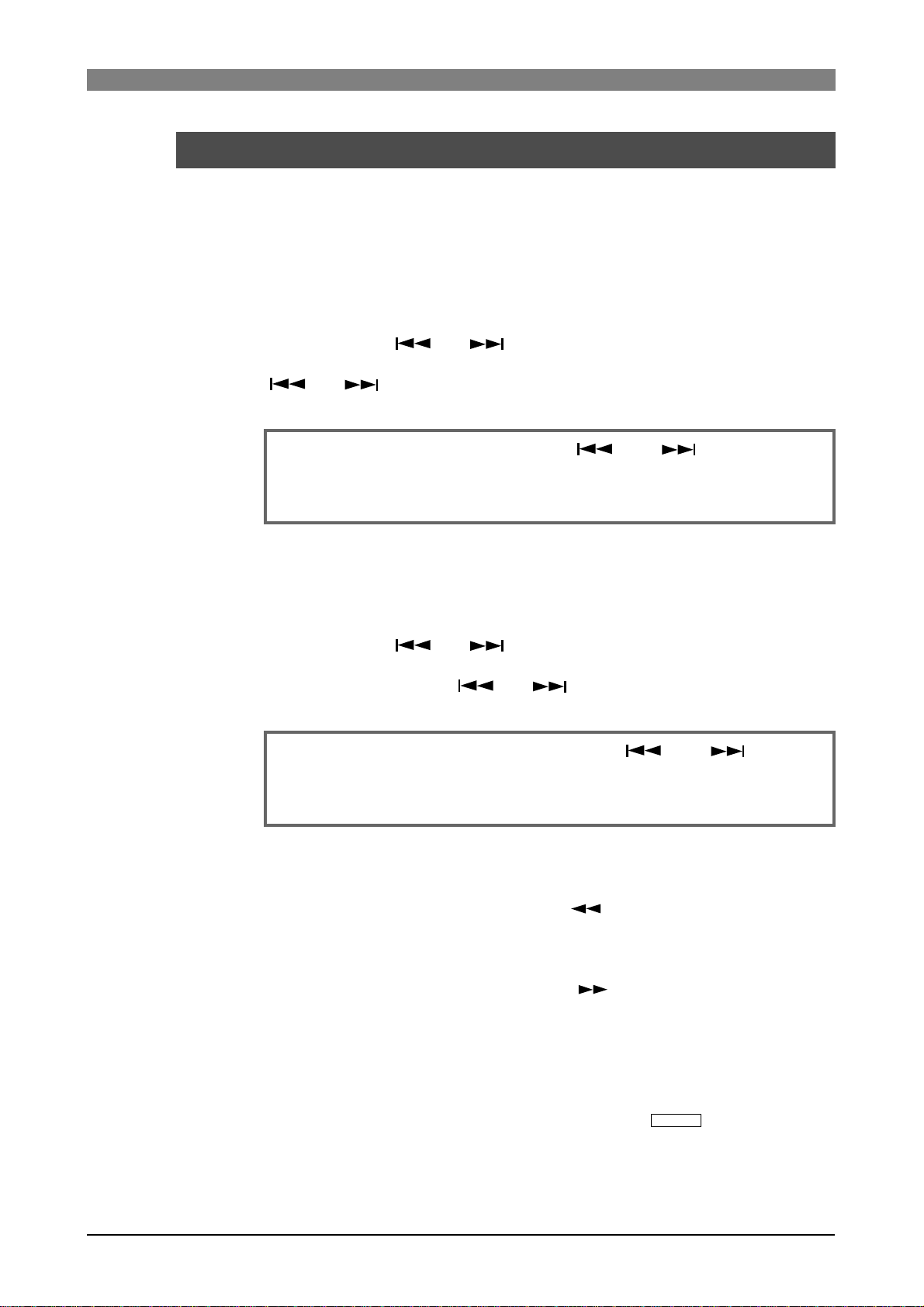
DVD Multitrack Recorder DV824DVD Multitrack Recorder DV824
DVD Multitrack Recorder DV824
DVD Multitrack Recorder DV824DVD Multitrack Recorder DV824
Skip/locate functions
The DV824 offers comprehensive skip/locate functions.
Skipping through files
When more than one audio file is recorded on the current DVD-RAM disk,
you can quickly skip to the beginning (ABS 0) of a desired audio file.
By pressing the [ ] or [ ] ([SKIP/CURSOR]) key while the unit is
stopped, you can skip forward or backward a file. Therefore, pressing the
[ ] or [ ] key as many times as required skips to the beginning of
the desired file.
<Note>:
mode" menu item in the "SYS SETUP" menu of the MENU mode must be set to
"File" (
the setting.
To skip through files using the [ ] and [ ] keys, the "Skip
see page 123 for details
). The default is "File". If it is set to "CUE", change
Skipping through cue points
You can quickly skip to a desired cue point on the current audio file.
By pressing the [ ] or [ ] ([SKIP/CURSOR]) key while the unit is
stopped, you can skip to the next or previous cue point.
Therefore, pressing the [ ] or [ ] key as many times as required
skips to the desired cue point.
<Note>:
"Skip mode" menu item in the "SYS SETUP" menu of the MENU mode must be
set to "CUE" (
"CUE".
To skip through cue points using the [ ] and [ ] keys, the
see page 123 for details
). The default is "File", so change it to
Locating to the beginning or end of a file
While the unit is stopped, pressing the [ REW] key while holding down
the [STOP/HOME] key locates to the beginning (ABS 0) of the current file
quickly.
While the unit is stopped, pressing the [ F FWD] key while holding
down the [STOP/HOME] key locates to the record end position (REC END)
of the current file quickly.
Locating to the last located point
While the unit is stopped, pressing the [LOCATE/
the point where you located last time.
EDIT TIME
] key locates to
61
Page 62

DVD Multitrack Recorder DV824DVD Multitrack Recorder DV824
DVD Multitrack Recorder DV824
DVD Multitrack Recorder DV824DVD Multitrack Recorder DV824
Locating to a desired time point
You can locate the unit to any desired point by specifying the time value.
1) While the unit is stopped (or playing back), press the [SHIFT] key to light
the [SHIFT] indicator, followed by the [LOCATE/
The DV824 enters the time edit mode and the popup window for entering
time data appears on the display.
EDIT TIME
] key.
flashing
<Note>:
selected before entering the time edit mode. In the screen example above,
you can specify the time value based on LTC.
The time value can be specified according to the time mode
2) Use the [MENU] dial (or alphanumeric keys) to enter the desired time value.
You can move the cursor position using the [SKIP/CURSOR ] keys.
Pressing the [CLEAR/
00f 00sf".
You can enter the time value between "00h00m00s00f00sf" and
"23h 59m 59s **f 99sf" (** depends on the frame rate of the audio file).
FALSE START
3) After entering the desired time value, press the [LOCATE/
The unit quickly locates to the point at the specified time.
<Note>:
press the [LOCATE/
operation is not executed.
If you enter a time value which is out to the current file and
EDIT TIME
] key resets the time value to "00h 00m 00s
EDIT TIME
] key, “Out of Zone” is shown and the locate
Locating to a desired cue point
You can locate the unit quickly to a desired cue point by selecting the cue
point from the cue list.
1) While the unit is stopped, press the [MARK/CUE] key.
The CUE LIST screen appears.
] key.
2) Use the [MENU] dial (or alphanumeric keys) to select the desired cue point
from the cue list, and press the [LOCATE/
The unit quickly locates to the selected cue point and the display returns to
the Home screen.
<Note>:
points", this function is always available regardless of the "Skip mode"
setting in the "SYS SETUP" menu of the MENU mode.
Unlike the function described above in "Skipping through cue
EDIT TIME
] key.
62
Page 63

DVD Multitrack Recorder DV824DVD Multitrack Recorder DV824
DVD Multitrack Recorder DV824
DVD Multitrack Recorder DV824DVD Multitrack Recorder DV824
Chapter-6: Ad vanced operations
Table of contents
Audio CD playbac k ...................................................................................................................................64
Setting CD stop mode .....................................................................................................................65
List play function ......................................................................................................................................66
Setting list play mode/Executing list play ..................................................................................68
Viewing linked audio files .............................................................................................................69
Locating to the beginning of the play list ....................................................................................69
Locating to the end of the play list ..............................................................................................69
Controlling the unit from a video editor ..................................................................................... ...........70
Necessary setting (RS422 SETUP menu) .....................................................................................70
RS422 remote setting .........................................................................................................70
Device type setting .............................................................................................................71
Sync play setting .................................................................................................................71
Editor preset setting ...........................................................................................................71
File data transfer using FTP server function .........................................................................................72
Setting example of PC connection ................................................................................................73
Connecting DV824 directly to PC .....................................................................................73
Connecting DV824 to LAN .................................................................................................74
FTP command details .........................................................................................................74
TCP/IP SETUP menu setting ..........................................................................................................75
IP address setting ................................................................................................................75
Subnet mask setting ...........................................................................................................75
Anonymous on/off setting ................................................................................................75
Login name/password setting ..........................................................................................76
TCP/IP Enable mode on/off setting ..................................................................................76
Mac address checking ........................................................................................................76
File transfer example between the DV824 and a PC ..................................................................78
Time code recording/playback (the optional Model 8348 required) ..................................................80
Recording time code ......................................................................................................................80
Frame rate setting ...............................................................................................................80
TC generator mode setting ................................................................................................80
Playing back time code ..................................................................................................................81
Time code output setting ...................................................................................................81
Jam function (the optional Model 8348 required) ................................................................................81
Executing jam function ..................................................................................................................82
Auto copy function (the optional Model 9057 required) ......................................................................83
Selecting auto copy mode .............................................................................................................83
Making auto copy ...........................................................................................................................85
Disk copy function (the optional Model 9057 required) ......................................................................86
Making Disk copy ...........................................................................................................................86
File copy function (the optional Model 9057 required) ........................................................................87
Making File copy .............................................................................................................................87
Dual drive recording (the optional Model 9057 required) ....................................................................89
Formatting in the "DDR" mode ....................................................................................................89
Making dual drive recording ........................................................................................................91
Chasing external TC (the optional Model 8348 required) ....................................................................92
Preparations ....................................................................................................................................92
Chasing ............................................................................................................................................92
Data export to PC (the optional Model 8370 required) .........................................................................93
Connecting PC to the unit ..............................................................................................................93
How to unmount the DV824 from the PC ...................................................................................94
Example of copying data to a computer hard disk ....................................................................94
Example of exporting data to a computer application ..............................................................95
63
Page 64

DVD Multitrack Recorder DV824DVD Multitrack Recorder DV824
DVD Multitrack Recorder DV824
DVD Multitrack Recorder DV824DVD Multitrack Recorder DV824
Audio CD pla ybac k
The DV824 can play back audio CDs (in the CD-DA format), as well as play back files
on a DVD-RAM disk. You can operate the DV824 for playing back an audio CD in a
similar way to an ordinary CD player.
<Note>:
able audio CDs. Note that, however, it may not be able to play back some CDs such as
copy-controlled CDs which are disc-protected.
Using the unit, you may play back commercially available audio CDs for your personal
use and enjoyment only. You may not use it for any commercial purpose whatsoever.
Unauthorized use is a violation of applicable laws and subject to criminal prosecution.
The DV824 can play back CD-DA format audio CDs including commercially avail-
Before playing back an audio CD by the unit, we recommend setting the "CD stop
mode" menu item in the "SYS SETUP" menu of the MENU mode appropriately (see the
next page).
1) Set an audio CD to the tray and load it.
The unit automatically recognizes the CD as the CD-DA format disc and the
display shows the Home screen for audio CD. The screen shows the following
information.
The current "CD stop
mode" setting.
You can make setting via the quick
setup mode or the
"CD stop mode"
menu item in the
"SYS SETUP" menu
of the MENU mode.
The current track number and the total number
of tracks.
The currently selected track number
is shown.
Total disc time is
shown.
The FS/Bit and the number of tracks of the disc are shown.
2) Press the [ PLAY] key to start pla ybac k.
When an audio CD is loaded, you can execute the following operations in addition
to normal playback.
• Locating to the beginning (or end) of a disc (see page 61)
While stopped, press the [REWIND] (or [F FWD]) key while holding down the
[STOP/HOME] key.
• Locating to a desired time position (see page 62)
Press the [SHIFT] key, followed by the [LOCATE] key. Then enter the desired time
value and press the [LOCATE] key.
• Cueing playback (see page 60).
Press the [REWIND] or [F FWD] key during playback.
• Track skip (see page 61)
Press the [SKIP/CURSOR ] or [SKIP/CURSOR ] key while stopped or during
playback mode.
• Track selection in FILE SEL mode (see the next pa ge)
64
Page 65

DVD Multitrack Recorder DV824DVD Multitrack Recorder DV824
DVD Multitrack Recorder DV824
DVD Multitrack Recorder DV824DVD Multitrack Recorder DV824
Track selection in the FILE SEL mode:
While an audio CD is loaded, pressing the [FILE SEL]
key brings up the screen for selecting a track of the
audio CD, as shown right (the time at the beginning of
each track is also shown).
By using the [MENU] dial to select the desired track
and pressing the [ENTER/YES] key, the display shows
the Home screen for the selected track.
Setting CD stop mode
You can select the CD stop mode which determines how audio CD playback stops. This
setting is only effective when playing back an audio CD (CD-DA). It does not affect DVDRAM disk playback. You can select the CD stop mode by the procedure below, as well as
via the quick setup mode.
1) While the unit is stopped, press the [ENTER/YES] key to enter the MENU mode.
The unit enters the MENU mode and the MENU list screen as below is shown.
2) While "SYS SETUP" is highlighted, press the [ENTER/YES] key.
The display now shows the SYS SETUP menu screen.
3) Use the [MENU] dial to select the "CD stop mode" menu item and press the
[ENTER/YES] key.
The current option (by default, "CD end") starts flashing and you can now select
the desired option.
Option
CD end
T rac k
Repeat
The unit plays back an audio CD from track 1 to the last track. When playback
of the last track ends, the unit automatically stops. This is the default.
When playback of the current track ends, the unit automatically stops.
The unit plays back an audio CD from track 1 to the last track repeatedly. It
continues playback until you stop it.
Function
4) Use the [MENU] dial to select the desired mode and press the [ENTER/YES] key to
confirm your setting.
Now you complete setting.
5) Press the [STOP/HOME] key to e xit the MENU mode.
Selecting the CD stop mode via the quick setup mode
While the Home screen for an audio CD is shown, press the [QUICK SET] key. Any
setting item start flashing.
• Use the [MENU] dial to flash "
• Use the [MENU] dial to select the desired CD stop mode.
• Press the [ENTER/YES] key to confirm the selection.
• Press the [STOP/HOME] key to exit the MENU mode.
" and press the [ENTER/YES] key.
65
Page 66

DVD Multitrack Recorder DV824DVD Multitrack Recorder DV824
DVD Multitrack Recorder DV824
DVD Multitrack Recorder DV824DVD Multitrack Recorder DV824
List play function
The LIST PLAY function allows linking multiple audio files recorded with the same FS
on the disk and play back them continuously.
<Note>:
desired audio files to the ALE file created using the "EDIT EDL FILE" menu item.
See page 99 for details about the "EDIT EDL FILE" menu item.
To execute list play by linking audio file entries in an ALE file, you must add the
There are four "link modes" for playing back linked audio files continuously, as below.
You can link any audio files recorded with same FS on a disk (or in an ALE file). Each
selected file is played back at its original LTC position while LTC runs. If two audio files
LTC-Link
Song-Link
overlaps the same L TC range, the file which has earlier LTC start time takes priority and
is played back while the other file is ignored (i.e. not played back).
After the unit finishes playback of the last file, playback continues while "<Silent>" is
shown on the screen.
You can link any audio files recorded with same FS on a disk (or in an ALE file). Selected
files are continuously played back (with no gaps) in order of date/time when each file is
added to the ALE file.
L TC starts from the LTC start time of the first audio file and jams the LTC of subsequent
audio files (therefore, continuous LTC is output).
In the Song link mode, you can also select “Stop Mode” from among List-End, Song,
Repeat and Off (the default is Off). The Stop mode decides how the unit stops link play.
See the next and the following pages for details.
You can link any audio files recorded with same FS on a disk (or in an ALE file). Selected
List-Link
Mid-Night
<Note>:
tion on the LTC stream.
"<Silent>" is shown when no file to be played back exists after the current posi-
files are continuously played back (with no gaps) in order of file number in the ALE file.
The unit outputs the original L TC of each audio file, so it is not always continuous.
When the unit finishes playing back the last file, it automatically stops.
This mode is basically the same as the LTC-Link mode, except that the LTC starts running from "12h00m00s00f", crosses "24h00m00s00f" and ends at one frame earlier than
"12h00m00s00f" of the next day .
Therefore, an audio file which starts from between "00h00m00s00f" and "12h00m00s00f"
is linked after "24h00m00s00f".
66
Page 67

DVD Multitrack Recorder DV824DVD Multitrack Recorder DV824
DVD Multitrack Recorder DV824
DVD Multitrack Recorder DV824DVD Multitrack Recorder DV824
Let's assume that the current DVD-RAM disk contains six audio files (including a
deleted file, "005") recorded with the same FS, and each audio file has the LTC start
time as shown below.
File No.
L TC start time
Recording time
001
30 seconds
002
30 seconds
003
01h01m25s00f
30 seconds
004
01h02m00s00f
30 seconds
005 (deleted)
-01h00m00s00f 01h01m00s00f
-
006
01h03m00s00f
30 seconds
If you execute list play of these files, they are played back as below.
List play in "LTC-Link" mode
The audio files are played back at their original positions in the LTC stream. When
executing list play in this mode, the unit plays back silence in the time code area
where no file is played back (between "File 001 and File 002).
File 003 is not played back because its start time overlaps the range of File 002. So
there is a 30-second silent area between File 002 and File 004.
The deleted file (005) is not played back so there is a 30-second silent area between
File 004 and File 006. After the unit finishes playback of the last file (006), playback
continues while "<Silent>" is shown on the screen.
File No. 001
01H00M00S00F
Silent Area
01H00M30S00F
File No. 002 File No. 004 File No. 006
01H01M00S00F 01H01M30S00F 01H02M00S00F 01H02M30S00F 01H03M00S00F 01H03M30S00F
Silent Area
Silent AreaSilent Area
List play in "Song-Link" mode
Files are continuously played back (with no gaps) in order of date/time when each
file is added to the ALE file.
All files except the deleted file (005) are played back in order of date/time (i.e. 001 > 002 -> 003 -> 004 -> 006).
LTC starts from the LTC start time of File 001 and jams the LTC of other audio files.
When the “Stop Mode”, which can be set only in the “Song-Link” mode, is set to the
default (Off), “<Silent>” is shown after finishing playback of the last file. However,
depending on “Stop Mode” setting, you can make the unit automatically stop after
finishing playback of the last file or repeat playback unitl you stop.
File No. 001
01H00M00S00F
File No. 002
01H00M30S00F
File No. 003 File No. 006
01H01M00S00F 01H01M30S00F 01H02M00S00F 01H02M30S00F
File No. 004
Silent Area
List play in "List-Link" mode
Files are continuously played back (with no gaps) in order of file number in the ALE
file (i.e. 001 -> 002 -> 003 -> 004 -> 006). The deleted file (005) is not played back.
When each file is played back, LTC recorded on the file is output (so output LTC is not
continuous).
Immediately after the unit finishes playback of the last file (006), playback automatically stops.
File No. 001
01H00M00S00F
File No. 002
01H01M00S00F
File No. 003 File No. 006
01H01M25S00F 01H02M00S00F 01H03M00S00F 01H03M30S00F
File No. 004
67
Page 68

DVD Multitrack Recorder DV824DVD Multitrack Recorder DV824
EDIT EDL
DVD Multitrack Recorder DV824
DVD Multitrack Recorder DV824DVD Multitrack Recorder DV824
Setting list play mode/Executing list pla y
Before executing list play, you must set the maximum number of tracks of a file which
can be linked and the link mode appropriately.
<Note>:
quick setup mode or the "Record FS/Bit" menu item in the "SYS SETUP" menu of the MENU
mode.
Before making setting for list play, select the FS of audio files to be linked via the
1) While the unit is stopped, press the [LIST PLAY/
The display now shows the screen for selecting a play list.
If no ALE file exists on the disk, only "<All Link>" is shown (highlighted) in the list
as below. If "<All Link>" is selected, all files with the same FS as the "Record FS/
Bit" setting can be linked.
<Note>:
exists on the disk, the ALE file names are also
listed as shown right.
To link audio file entries in an ALE file, use the
[MENU] dial to select the desired ALE file name
and press the [ENTER/YES] key.
<Note>:
which includes all available files on the disk.
If ALE files containing audio file entries
If "<All Link>" is selected, the unit automatically creates the ALE file
] key.
2) While "<All Link>" is highlighted, press the [ENTER/YES] key.
The display now shows the screen for setting "Link Track (max)" and the "Link
Mode". By default, "Link Track (max)" is set to the current "Record tracks" setting,
while "Link Mode" is set to "LTC-Link".
3) Select the desired link track and link mode.
• "Link Track (max)" setting
This item set the maximum number of tracks of a file which can be linked.
By using the [MENU] dial to select "Link Track (max)" and pressing the [ENTER/
YES] key, the current setting starts flashing and you can now select the desired
maximum number of tracks from among "1trk", "2trk", "4trk", "5trk", "6trk" and
"8trk".
The selected maximum number of tracks is reflected to the "
status information area on the Home screen.
TRACK
" field in the
68
Page 69

DVD Multitrack Recorder DV824DVD Multitrack Recorder DV824
DVD Multitrack Recorder DV824
DVD Multitrack Recorder DV824DVD Multitrack Recorder DV824
<Note>:
number of tracks is equal to or less than the selected number.
For example, if you set "Link Track (max)" to "4trk", you can link 2-track and
1-track files, as well as 4-track files.
The selected number is the maximum. You can link any file whose
• "Link Mode" setting
By using the [MENU] dial to select "Link Mode" and pressing the [ENTER/YES] key,
the current setting starts flashing.
By rotating the [MENU] dial, you can select from among "Song-Link", "List-Link"
and "Mid-Night", as well as "LTC-Link". If you select "Song-Link", the "Stop Mode"
item is shown on the display (see below). The "Stop Mode" selects how the unit
stops link play.
<About "Stop Mode">
When you set "Link Mode" to "Song-Link", you can select the "Stop Mode"
from among List-End, Song, Repeat and Off (the default is Off), which decides
how the unit stops link play. By selecting "Song-Link" for "Link Mode" and
pressing the [ENTER/YES] key, the current option of "Link Mode" starts flashing and you can now select the desired option using the [MENU] dial.
After selecting the desired option using the [MENU] dial, press the [ENTER/
YES] key to confirm your setting.
Off
List-End
Song
The unit continues playback until it reaches 24H. When it reaches 24H, it
stops (default).
The unit executes seamless playback of files in the list. After finishing playback of the last file in the list, it pauses at the start position of the first file in
the list. Pressing the [PLAY] key again starts playback and executes the
same as above.
After finishing playback of the first file in the list, it pauses at the start position
of the next file in the list. Pressing the [PLAY] key again starts playback and
executes the same as above.
Repeat
The unit executes seamless playback of files in the list. After finishing playback of the last file in the list, it starts playback from the first file in the list. The
unit repeats playback until you stop.
69
Page 70

DVD Multitrack Recorder DV824DVD Multitrack Recorder DV824
DVD Multitrack Recorder DV824
DVD Multitrack Recorder DV824DVD Multitrack Recorder DV824
<Note>:
"CUE 01 (BC$START)" and "CUE 02 (BC$END)" are set in a linked file, the unit
only plays back the file within the range between "CUE 01 (BC$START)" and
"CUE 02 (BC$END)".
If you want to play back all data of the file, delete the cues labeled "BC$START"
and "BC$END" or edit "BC$START" and "BC$END" to other labels.
When playing back a file while the link mode is set to "Song-Link", if
4) Highlight "EXECUTE" and press the [ENTER/YES] key.
After "Please wait!" is shown, the play list is created. The display changes to shows
the Home screen of the first audio file of the link, while the [LIST PLAY] indicator
lights, indicating that the list play mode is now active.
5) Press the [PLAY] key.
The unit starts continuous playback according to the selected link mode.
<Note>:
key brings up the screen for selecting the play list, so you can change the play
list.
While the Home screen above is shown, pressing the [FILE SEL/
DRV/PAT
]
Viewing linked audio files
When the list play mode is active and the unit is stopped, pressing the [SKIP/
CURSOR ] or [SKIP/CURSOR ] key locates to the beginning of a linked
audio file. Using this function, you can check which audio files are linked and in
which order files are linked.
Locating to the beginning of the play list
When the list play mode is active and the unit is stopped, pressing the [RE
WIND] key while holding down the [STOP/HOME] key locates to the beginning
of the first audio file of the link (Locate ABS 0).
Locating to the end of the play list
When the list play mode is active and the unit is stopped, pressing the [F FWD]
key while holding down the [STOP/HOME] key locates to the end of the last
audio file of the link (Locate REC END).
70
Page 71

DVD Multitrack Recorder DV824DVD Multitrack Recorder DV824
DVD Multitrack Recorder DV824
DVD Multitrack Recorder DV824DVD Multitrack Recorder DV824
Controlling the unit fr om a video editor
The following describes necessary settings for controlling the DV824 from an external video editor via P2/ES BUSS (RS-422).
HOUSE SYNC
7
8
1:GND 2:HOT 3:COLD
876
6
ANALOG INPUT BALANCED [+4dBu]
ANALOG OUTPUT BALANCED [+4dBu]
543
Video Sync
1
2345
21
Audio signal
Digital Mixer
Video Editor
RS422
PARALLEL
REMOTE
INPUT
WORD
WORD
INPUT
OUTPUT
75Ω
ON
OFF
DIGITAL I/O AES/EBU
ETHERNET
P2/ES BUSS
100Ω
ON OFF
Word
Video Sync
INPUT
TIME CODE
VTR
OUTPUT
DC-IN 12V
1:GND
2:NC
3:NC
4:12V
Audio signal
RS422
THRU
LEVEL SEL
BI-PHASE INPUT
24V5V
LINKTX/RX
Necessary setting (RS422 SETUP menu)
To control the DV824 from an external video editor, etc., you must make necessary settings
via the "RS422 SETUP" menu of the MENU mode by following the procedure below.
1) While the unit is stopped, press the [ENTER/YES] key to enter the MENU mode.
2) Use the [MENU] dial to select the "RS422 SETUP" menu and press the [ENTER/
YES] key.
The display now shows the RS422 menu screen for selecting a menu item.
By using the [MENU] dial to select a desired menu item and pressing the [ENTER/
YES] key, you can make setting for the menu item. See the following for details of
setting for each menu item.
RS422 remote setting (Selection of the device(s) controlling the DV824)
You can select from among "Both" (default), "Local" and "Remote".
Use the [MENU] dial to select the desired option and press the [ENTER/YES] key to
confirm your selection.
Both
Local
Remote
Y ou can control the unit from both panel keys and RS422 remote. This is the default setting.
You can control the unit from panel keys. RS422 remote control is disabled.
You can control the unit from RS422 remote. Panel key control is disabled.
71
Page 72

DVD Multitrack Recorder DV824DVD Multitrack Recorder DV824
DVD Multitrack Recorder DV824
DVD Multitrack Recorder DV824DVD Multitrack Recorder DV824
Device type setting (Selection of the DV824 device type)
You can select between "DVD" (default) and "BVW-75".
Use the [MENU] dial to select the desired device type and press the [ENTER/YES]
key to confirm your selection.
DVD
BVW-75
The device type is set to DV824.
The device type is set to BVW-75.
Sync play setting (On/Off selection of Sync play)
You can select whether or not the unit locks to the incoming video reference when
it receives the PLAY command via RS-422 and plays.
Use the [MENU] dial to select "On" or "Off" and press the [ENTER/YES] key to
confirm your selection. When connecting an editor to the unit, select "On".
Off
On
The sync play does not function. The unit does not lock to the incoming video reference.
The sync play functions. The unit locks to the incoming video reference.
Editor preset setting (Global setting for editor connection)
You can preset the DV824 to work with an editor in the best condition by setting
this item appropriately.
Use the [MENU] dial to select between "Video" and "Lynx" and press the [ENTER/
YES] key to confirm your selection.
Video
Lynx
The unit is preset to be controlled by a video editor.
The unit is preset to be controlled by the Lynx synchronizer .
3) After making settings appropriately , press the [EXIT/NO] ke y (or the [ST OP/HOME]
key) to exit the MENU mode.
72
Page 73

DVD Multitrack Recorder DV824DVD Multitrack Recorder DV824
DVD Multitrack Recorder DV824
DVD Multitrack Recorder DV824DVD Multitrack Recorder DV824
File data transfer using FTP server function
By connecting the [ETHERNET] port on the DV824 to your personal computer using
a LAN cable, the DV824 acts as an FTP (File Transfer Protocol) server, allowing transferring audio file data between the DV824 and your personal computer via TCP/IP.
The FTP client application is used when transferring file data.
PARALLEL
7
8
1:GND 2:HOT 3:COLD
876
6
ANALOG INPUT BALANCED [+4dBu]
ANALOG OUTPUT BALANCED [+4dBu]
543
1
2345
21
<Connecting with a personal computer>
To connect the DV824 [ETHERNET] port to a personal computer, use a "category 5" LAN cable conformed to "10BASE-T" and "100BASE-TX".
If you connect the DV824 to a personal computer via a switching hub, use
straight cables between the DV824 and the switching hub, and between the
switching hub and the personal computer.
If you connect the DV824 directly to a personal computer, use a cross cable.
REMOTE
ON
DIGITAL I/O AES/EBU
P2/ES BUSS
THRU
INPUT
100Ω
ON OFF
WORD
WORD
INPUT
OUTPUT
LEVEL SEL
75Ω
24V5V
OFF
ETHERNET
LINKTX/RX
BI-PHASE INPUT
TIME CODE
INPUT
OUTPUT
DC-IN 12V
1:GND
2:NC
3:NC
4:12V
Straight cable
1
2
3
4
5
6
7
8
1
2
3
4
5
6
7
8
1
2
3
4
5
6
7
8
Cross cable
1
2
3
4
5
6
7
8
<FTP client applications>
Fostex has checked the following FTP client applications.
• Already confirmed applications: Fetch (shareware for Macintosh)
WS FTP (shareware for Windows)
• Unusable application: FTP Explorer (shareware for Windows)
<Where audio files are stored?>
"BWF" audio files is stored in the "bwff" folder.
Note that only audio files with the ".wav" extension are stored in the "bwff"
folder.
73
Page 74

DVD Multitrack Recorder DV824DVD Multitrack Recorder DV824
DVD Multitrack Recorder DV824
DVD Multitrack Recorder DV824DVD Multitrack Recorder DV824
Setting example of PC connection
The following shows the typical example of connecting a PC to the DV824.
It is assumed that a LAN card is installed to the PC and set to work correctly. Note that
there may be some difference between the description below and your actual setting.
<Note>:
typical environment. Note that, depending on the computer environment, the DV824
may work correctly by setting a different value or may not work correctly by setting
the value shown below.
The IP address and sub net mask value shown below are those used in a
Connecting DV824 directl y to PC
The following procedure shows how to connect the DV824 directly to a PC, without
connecting to LAN. It is assumed that the DV824 is connected to the PC using a cross
cable.
1) Set the items in the "TCP/IP SETUP" menu of the DV824 MENU mode as below
(see page 76 for details).
• IP address: 192.168.0.*** (*** is a desired number between 1 and 254.)
• Sub net mask: 255.255.255.0
• Anonymous: On (Enable)
• Login name: No need to set.
• User password: No need to set.
• TCP/IP Enable: On (Enable)
<Note>:
checked when logging in. Therefore, you can log in regardless of the user
name and password settings (including blank).
If "Anonymous" is set to "On", the user name and password are not
2) Make TCP/IP setting on the PC.
• IP address: 192. 168. 0. *** (*** is a desired value between 1 and 254.)
<Important!>: You cannot assign the same IP address as the DV824 IP address.
• Sub net mask: Set the same value as the DV824.
• Default gateway: No need to be set.
<Note>:
PC for details about the TCP/IP setting.
If it is not clear how to make the TCP/IP setting, see "Help" of your
3) Start up the FTP application of the PC, and make setting for connection.
<Setting of WS-FTP>
• Profile Name: A desired name
• HostName/Address: 192. 168. 0. ###
(### must be the same value as the DV824 IP address.)
• HostType: Automatic detect
• Anonymous: Enable (On)
• User ID: Does not need to be set.
• Password: No need to be set.
<Setting of Fetch>
From the "Custom" menu in the menu bar, select "New shortcut" and set the
items below.
• Name: A desired name
• Type: Folder
• Server name: 192. 168. 0. ###
(### must be the same value as the DV824 IP address.)
• User name/Password: No need to be set.
• Directory: / (slash)
74
Page 75

DVD Multitrack Recorder DV824DVD Multitrack Recorder DV824
DVD Multitrack Recorder DV824
DVD Multitrack Recorder DV824DVD Multitrack Recorder DV824
4) Open the connection with the setting above, and transf er a file.
<If you use WS-FTP>
Before transferring a file, select "Binary" or "Auto" from among "ASCII",
"Binary" and "Auto" shown in the center of the window.
<If you use Fetch>
Before transferring a file, set "Mode" to "Auto" and "Format" to "RawData".
Connecting DV824 to LAN
To connect the DV824 to a LAN, use a straight cable to connect the DV824 to a hub.
For details about FTP application setting, see "Connecting DV824 directly to PC" described above.
<Note>:
If the IP address or sub net mask is not appropriately set when connecting
the DV824 to a LAN, it may give bad influence to the LAN. Consult a network administrator if you need help for setting these items appropriately.
FTP command details
The following shows usable and unusable FTP commands when you can use the DV824
as the FTP server.
<Note>:
time.
• The following FTP commands can be used when
DV824 works as a FTP server .
USER
PASS
QUIT
PORT
TYPE
RETR
STOR
LIST
NLST
CWD
CDUP
PWD
NOOP
SYST
Only a single user can log in. More than one user cannot log in at the same
• The following FTP commands cannot be used when
DV824 works as a FTP server.
Identifying user name.
Identifying password.
T erminating FTP connection. TCP connection
for Control is also cut off.
When transferring data, relay the connection state open port number for data transferring at client side to server.
Format: PORT IP1, IP2, IP3, IP4, P1, P2
(IPx: IP address, Px: port number represented
by decimal number in every 1 byte unit)
Designating data type (ASCII, BECIDIC, BINARY, LOCAL).
Instructing server to transfer file though data
connection.
Instructing server to write data transferred
through data connection into a new file.
Requesting server to send a list of files.
Requesting server to send a detailed list of
files.
Changing current directory.
Changing current directory to upper level.
Displaying current directory.
Doing nothing.
Acquire server OS type.
Instructing server to write data transferred
APPE
through data connection into an existing file
additionally.
DELE
RNFR
RNTO
HELP
ACCT
STRU
MODE
Deleting designated file.
Designating current file name for renaming.
Changing current file name for renaming.
Displaying command description.
Identifying user account.
Opening command state designated port ex-
PASV
cept default data port (No, 20) on server.
Designating file structure.
Designating file transfer mode (Stream,
Block, Compressed).
RMD
Deleting designated directory.
MKD
Creating designated directory.
ST AT
Requesting server condition.
75
Page 76
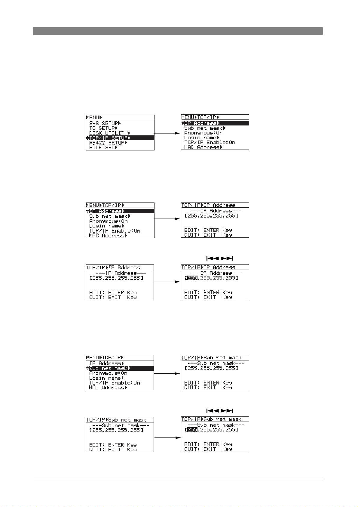
DVD Multitrack Recorder DV824DVD Multitrack Recorder DV824
DVD Multitrack Recorder DV824
DVD Multitrack Recorder DV824DVD Multitrack Recorder DV824
TCP/IP SETUP menu setting
To connect the DV824 [ETHERNET] port to a PC. make settings of the "TCP/IP SETUP" menu in
the MENU mode appropriately. See below for details of how to make "TCP/IP SETUP" menu
settings.
1) While the unit is stopped, press the [ENTER/YES] ke y to enter the MENU mode.
2) Use the [MENU] dial to select "TCP/IP SETUP" and press the [ENTER/YES] key.
The display now shows the screen for selecting the menu item.
3) Use the [MENU] dial to select a desired menu item and press the [ENTER/YES] key.
You can now edit the menu item (see below for details).
• IP address setting
The "IP Address" menu item sets the IP Address on DV824.
By selecting "IP Address" and pressing the [ENTER/YES] key, the current IP address is
shown (by default, "192. 168. 1. 188.").
By pressing the [ENTER/YES] key again, the leftmost three-digit number starts flashing.
You can now enter the desired value using the [MENU] dial (or alphanumeric keys),
while you can move the cursor using the [SKIP/CURSOR ] key.
After completing editing, press the [ENTER/YES] key to confirm the setting.
• Sub net mask setting
The "Sub net mask" item sets the sub net mask value in the network DV824 exists. In the
case the Sub net mask is not used, you do not have to set this value.
By selecting "Sub net mask" and pressing the [ENTER/YES] key, the current Sub net
mask is shown (by default, "255. 255. 255. 0.").
By pressing the [ENTER/YES] key again, the leftmost three-digit number starts flashing.
You can now enter the desired value using the [MENU] dial (or alphanumeric keys),
while you can move the cursor using the [SKIP/CURSOR ] key.
After completing editing, press the [ENTER/YES] key to confirm the setting.
76
Page 77

DVD Multitrack Recorder DV824DVD Multitrack Recorder DV824
DVD Multitrack Recorder DV824
DVD Multitrack Recorder DV824DVD Multitrack Recorder DV824
• Anonymous on/off setting
The "Anonymous" menu item sets the anonymous On/Off.
By selecting "Anonymous" and pressing the [ENTER/YES] key, the current setting
is shown (by default, "On"). While the DV824 is connected to a PC and used as an
FTP server, if "Anonymous" is set to "On", you do not need to set the login name
and password.
After selecting "On" or "Off" using the [MENU] dial, press the [ENTER/YES] key to
confirm the setting.
• Login name/password setting
The "Login name" menu item sets the login name (user name) and password.
Using the Login name and the Password set in this menu item, you can log in from
an FTP client application. By default, both "Login name" and "Password" fields are
blank. In this condition, you can log in. By selecting "Login name" and pressing
the [ENTER/YES] key, the display shows the screen for setting the login name and
password (by default, both fields are blank).
By pressing the [ENTER/YES] key again, you can now edit the login name.
After entering the desired name using the [MENU] dial (or alphanumeric keys),
press the [ENTER/YES] key to confirm the setting. Now you can enter the password. Enter the desired password in the similar way as above, and press the [ENTER/YES] key to confirm the setting.
• TCP/IP Enable mode on/off setting
The "TCP/IP Enable" menu item selects FTP commands enabled ("On") or disabled ("Off"). By selecting "TCP/IP Enable" and pressing the [ENTER/YES] key, the
current setting ("On" or "Off") is shown (by default, "On").
After selecting "On" or "Off" using the [MENU] dial, press the [ENTER/YES] key to
confirm the setting.
• Mac address checking
The MAC (Machine Access Control) address can be checked but not changed.
By selecting "MAC address" and pressing the [ENTER/YES] key, the MAC address
assigned to the DV824 is shown. It can be checked but not changed.
Press the [EXIT/NO key to exit the screen for showing the MAC address.
77
Page 78

DVD Multitrack Recorder DV824DVD Multitrack Recorder DV824
DVD Multitrack Recorder DV824
DVD Multitrack Recorder DV824DVD Multitrack Recorder DV824
File transfer example between the D V824 and a PC
The following shows the procedure example of transfer an audio file using the
"WS FTP" Windows FTP client application (see the instructions of the FTP
application for details).
1) Start up the "WS FTP" application.
The "Session Properties" dialog box in which current settings such as "IP address"
are shown appears.
2) Click on "OK" in the "Session Properties" dialog box.
You can now see the DV824 drive (and the partitions of the optional hard disk
drive if it is installed) in the right window, as below.
Select Binary or Auto.
3) Click on the desired drive.
In the window example below, partition (PT1) of the optional hard disk opens
and the “bwff” folder is shown.
78
Page 79

DVD Multitrack Recorder DV824DVD Multitrack Recorder DV824
DVD Multitrack Recorder DV824
DVD Multitrack Recorder DV824DVD Multitrack Recorder DV824
4) Click on the "bwf" folder.
As shown in the window example below, audio files recorded in the selected
partition are shown under the Info. folder.
You can now transfer an audio file from the DV824 to the PC or vice versa.
• Transferring an audio file from the DV824 to the PC
Highlight an audio file in the right window (for the DV824) and click on "<-".
The selected audio file is transferred from the DV824 (right window) to the PC
(left window).
• Transferring an audio file fr om the PC to the DV824
Highlight an audio file in the left window (for the PC) and click on "->".
The selected audio file is transferred from the PC (left window) to the DV824
(right window).
79
Page 80

DVD Multitrack Recorder DV824DVD Multitrack Recorder DV824
DVD Multitrack Recorder DV824
DVD Multitrack Recorder DV824DVD Multitrack Recorder DV824
Time code recording/playbac k (the optional Model 8348 required)
Recording time code
By installing the optional TC/SYNC card (Model 8348) to the DV824, you can record
time code generated by the internal TC generator along with audio signals, or record
incoming external time code. Furthermore, you can record internal generator time
code which jams to external time code.
<Note>:
You can make settings for time code recording/playback via the "TC SETUP"
menu on the MENU mode.
6
7
8
1:GND 2:HOT 3:COLD
876
ANALOG INPUT BALANCED [+4dBu]
ANALOG OUTPUT BALANCED [+4dBu]
543
Frame rate setting
You can select the desired frame rate via the quick setup mode, as
described on page 46. (You can also select the frame rate via the "Frame
Rate" menu item in the "TC SETUP" menu of the MENU mode. See page
127.)
<Note>:
frame rate of external time code by selecting the time mode to "TC IN" using
the [TIME SEL] key.
When recording external time code, you can view time value and
See page 125 for details
PARALLEL
1
2345
21
REMOTE
75‰
ON
OFF
DIGITAL I/O AES/EBU
.
INPUT
WORD(VIDEO)
INPUT
P2/ES BUSS
THRU
100‰
ON OFF
WORD
OUTPUT
LEVEL SEL
24V5V
ETHERNET
LINKTX/RX
Time code input
BI-PHASE INPUT
TIME CODE
INPUT
OUTPUT
Time code output
DC-IN 12V
1:GND
2:NC
3:NC
4:12V
TC generator mode setting
Depending on the TC generator mode, the unit records time code
differently.
You can select the desired TC generator mode via the quick setup mode,
as described on page 47. (You can also select the TC generator mode via
the "Gen Mode" menu item in the "TC SETUP" menu of the MENU mode.
See page 128 for details.) The following four generator modes are available.
24H Run
Rec Run
Free Run
EXT Run
When recording, the unit records time code based on the current internal
RTC (real-time clock) time.
When recording, the unit records time code which continues from the last
time code value of the previous audio file.
If you change to a new disk which does not have any audio file and make
recording, the unit records time code which continues from the last time
code value of the most recent audio file on the disk previously set.
When recording, the unit records time code generated by the internal generator which runs freely.
When recording, the unit records the incoming external time code.
80
Page 81

DVD Multitrack Recorder DV824DVD Multitrack Recorder DV824
DVD Multitrack Recorder DV824
DVD Multitrack Recorder DV824DVD Multitrack Recorder DV824
Playing back time code
During playback, time code recorded on an audio file is played back together with audio signals and output from the [TIME CODE OUTPUT] connector provided with the optional TC/SYNC card. The playback time code
value is shown on the display when the time mode is set to "LTC".
Time code output setting
You can select the time code source fed from the [TIME CODE OUT] connector between "Repro" (playback time code) or "Gen" (generator time
code) via the "Sel. TC Out" menu item in the "TC SETUP" menu of the
MENU mode. The default is "Gen". See page 131 for details.
<Note>:
MENU mode is set to "Gen", the [TIME CODE OUTPUT] connector outputs
time code generated by the internal TC generator.
<Note>:
the following conditions:
• When "Gen Mode" is set to "Free Run".
If necessary, the following menu items in the "TC SETUP" menu should be
appropriately set.
When the "Sel. TC Out" menu item in the "TC SETUP" menu of the
While "Sel. TC Out" is set to "Gen", generator time code is output in
<Menu items which affect time code output>
1) "Edit LTC Start" menu item (for LTC start time setting). See page 132.
2) "Rep Pause TC" menu item (for TC output while paused). See page 134.
3) "Rep TC Ubit" menu item (for userbit setting of playback time code). See
page 133.
Jam function (the optional Model 8348 required)
The jam function of the DV824 internal generator allows taking over generating time
code after the generator locks to the external time code timing.
Using the jam function, even if time code connection is cut after lock is achieved, the
DV824 time code generator can run with extreme accuracy (its own crystal accuracy). Therefore, the DV824 can stripe time code in sync with the separated external
machine.
To execute the jam function, the following condition must be satisfied.
1) External TC is fed to the [TIME CODE INPUT] connector which is provided
with the optional TC/SYNC card.
2) The frame rate matches between external TC and the DV824.
3) "Gen Mode" is set to "Free Run" (see page 128 for details).
* The time display mode is set to "TC IN" and external TC value is shown.
81
Page 82

DVD Multitrack Recorder DV824DVD Multitrack Recorder DV824
DVD Multitrack Recorder DV824
DVD Multitrack Recorder DV824DVD Multitrack Recorder DV824
<Note>:
rate of external time code does not match the DV824 frame rate, "Illegal Frame!" is shown
on the display for warning.
If you are going to initiate the jam function while external time code is not normally fed to
the DV824, "Void LTC in!" is shown on the display for warning.
If you are going to jam the external time code into the generator while the frame
Executing jam function
The following describes how to execute the jam function.
1) While the unit is stopped, press the [ENTER/YES] key to enter the MENU mode.
The unit enters the MENU mode and the MENU list screen.
2) Use the [MENU] dial to select "TC SETUP" and press the [ENTER/YES] key.
The display now shows the TC SETUP menu screen.
3) Use the [MENU] dial to select the "Force JAM" menu item and press the
[ENTER/YES] key.
The display now shows the Force JAM screen, where time value and userbit
information of the external TC and generator TC is shown.
4) Press the [ENTER/YES] key to execute the jam function.
The external time code is jammed into the internal time code, and the jammed
time code is counted up.
By default, both the time value and userbit of the external time code are jammed.
However, via the "JAM mode" menu item in the "TC SETUP" menu, you can change
this setting to jamming only the time code value or only the userbit (see page 130
for details).
5) T o e xit the jam function, press the [EXIT/NO] key.
82
Page 83

DVD Multitrack Recorder DV824DVD Multitrack Recorder DV824
DVD Multitrack Recorder DV824
DVD Multitrack Recorder DV824DVD Multitrack Recorder DV824
Auto cop y function (the optional Model 9057 required)
When recording to an audio file on a partition of the Model 9057 optional hard disk
drive, the auto copy function automatically copies the same audio file to a DVD-RAM
disk. You can select the auto copy mode between the following two auto copy modes.
Copy recording to a DVD-RAM disk is executed simultaneously when recording to a
hard disk partition.
Immediately mode
Background mode
The recording size of a take is limited to the capacity of the hard disk partition or
DVD-RAM disk.
<Note>: In this mode, if no DVD-RAM disk is set, the DV824 cancels the auto copy
mode and returns to the normal recording mode.
Immediately after the DV824 ends recording to the partition and stops, the copy
starts.
In this mode, even if no DVD-RAM disk is set when starting recording, you can start
copying by setting a disk later.
<Note>: If you turn off the DV824 before setting a DVD-RAM disk, the copy data is
erased.
<Note>:
While the auto copy mode is "On" and a DVD-RAM disk is set to the DVD-RAM
drive, if the partition you are going to record to is formatted in the "DDR" mode (for dual
drive recording), dual recording takes priority to auto copy.
<Note>:
Editing the name or meta data of the file on the partition does not reflect to the
data on the DVD-RAM disk.
<Note>:
Auto copy cannot be canceled by False start.
Selecting auto copy mode
The following procedure is assumed that a recordable DVD-RAM disk is set to the
DVD-RAM drive.
1) Select a partition to which audio data is recorded.
By pressing the [SHIFT] key to turn on the [SHIFT] indicator followed by the
DRV/PAT
[FILE SEL/
In this screen, "DVD" represents the DVD-RAM drive, while "PT01" through "PT08"
represent the hard disk partitions.
SHIFT
] key, the display shows the "DRIVE SEL" screen.
FILE SEL
2
ABC
DRV/PAT
<Note>:
The optional hard disk drive is formatted when it is installed by the
Fostex service section, and divided into eight partitions. Each partition reserves
4.7GB recording space.
By using the [MENU] dial to select the desired partition and pressing the [ENTER/
YES] key, the display changes to show the Home screen for the selected partition.
If no file is recorded to the partition, "-No files!-" is shown as below.
83
Page 84

DVD Multitrack Recorder DV824DVD Multitrack Recorder DV824
DVD Multitrack Recorder DV824
DVD Multitrack Recorder DV824DVD Multitrack Recorder DV824
2) While the unit is stopped, press the [ENTER/YES] key to enter the MENU mode.
The display now shows the MENU list screen.
3) While "SYS SETUP" is highlighted, press the [ENTER/YES] key.
The display now shows the SYS SETUP menu screen.
4) Use the [MENU] dial to select the "Auto copy" menu item and press the [ENTER/
YES] key.
The current setting flashes and you can now select the desired auto copy mode.
By default, "Off" flashes.
You can select from among "Off", "BGRD (Background) and "IMME" (Immediately).
5) Use the [MENU] dial to select the desired option and press the [ENTER/YES] key.
After the display shows "Setup auto copy" followed by "Ready auto copy", the
selected mode is set.
The setting is stored to the DV824 flash ROM.
In this procedure example, it is assumed that "IMME" (Immediately) is selected.
6) Press the [STOP/HOME] key to e xit the MENU mode.
The display now shows the Home screen for the partition.
According to the copy mode selection in step 5) above, "
"IMME") or " " icon (when selecting "BGRD") is shown on the left of the status
information area.
" icon (when selecting
84
Page 85

DVD Multitrack Recorder DV824DVD Multitrack Recorder DV824
DVD Multitrack Recorder DV824
DVD Multitrack Recorder DV824DVD Multitrack Recorder DV824
Making auto copy
1) Press the [SAFE/RDY] key to make the unit record ready (the [SAFE/RDY]
indicator flashes).
By making the unit record ready while the auto copy mode is active, the copy
source (partition) remaining time and copy destination (DVD-RAM disk)
remaining time is alternately shown.
SAFE/RDY
9
WXYZ
2) Press the [RECORD] key to start recording to the partition.
When the auto copy mode is set to "IMME", audio data is recorded to the
partition, while it is copied to the DV824 DVD-RAM disk.
3) Press the [STOP/HOME] key to stop recor ding.
BKUP **h**m**s
If you choose the "BGRD" (Background mode) in step 4) and execute recording,
auto copy actually starts when pressing the [STOP/HOME] key to stop recording.
When starting auto copy, "Backup Copy start!" is shown on the display for a few
seconds, and immediately after auto copy finishes, "Backup Copy Finished!" is shown.
In the "BGRD" (background) mode, even if no DVD-RAM disk is set, the DV824
makes recording to the partition. In such a case, the copy data remains internally
after recording to the partition finishes, therefore, auto copy is executed when setting a blank DVD-RAM disk.
<Note>:
RAM) disk, the copy data remains until turning off the unit. however, once you
turn off the unit, the copy data is erased and the unit does not execute auto
copy.
<Note>:
"Off".
If you execute auto copy without setting a copy destination (blank DVD-
If you do not need to make auto copy, set the "Auto copy" menu item back to
85
Page 86

DVD Multitrack Recorder DV824DVD Multitrack Recorder DV824
DVD Multitrack Recorder DV824
DVD Multitrack Recorder DV824DVD Multitrack Recorder DV824
Disk copy function (the optional Model 9057 required)
The disk copy function fully copies all audio files recorded on a DVD-RAM disk (or
hard disk partition) to another DVD-RAM disk (or hard disk partition).
To execute the disk copy function, use the "Disk copy" menu item in the "DISK UTILITY" menu of the MENU mode.
Making disk copy
The following procedure is assumed that the DVD-RAM drive is selected and an audio
file on a DVD-RAM disk is loaded.
1) While the unit is stopped, press the [ENTER/YES] key to enter the MENU mode.
The display now shows the MENU list screen.
2) Use the [MENU] dial to select "DISK UTILITY" and press the [ENTER/YES] key.
The display now shows the DISK UTILITY menu screen.
3) Use the [MENU] dial to select "Disk copy" and press the [ENTER/YES] key.
The display now shows the screen for selecting the copy destination (DVD-RAM
drive or partition).
4) Use the [MENU] dial to select the copy destination (DVD-RAM drive or partition)
and press the [ENTER/YES] key.
The display shows the "CAUTION" message on which "Are you sure?" flashes, as
shown below.
In the bottom of this message screen, the approximate time required for disk copy
is shown.
86
Page 87

DVD Multitrack Recorder DV824DVD Multitrack Recorder DV824
DVD Multitrack Recorder DV824
DVD Multitrack Recorder DV824DVD Multitrack Recorder DV824
<Note>:
copy source. If you do so, the display shows "Void!" and returns to the screen
for selecting the copy destination medium.
5) If you are sure, press the [ENTER/YES] ke y.
The DV824 starts disk copy to the selected destination medium.
During disk copy, the display shows estimated time and space remaining progress
indication for disk copy.
When disk copy completes, "Completed!" is shown on the display and the DV824
stops disk access.
6) Press the [STOP/HOME] key to e xit the MENU mode.
The display shows the Home screen for the copy source medium.
You cannot select the disk copy destination to the same medium as the
File copy function (the optional Model 9057 required)
The disk copy function copies an audio file recorded on a DVD-RAM disk (or hard
disk partition) to another DVD-RAM disk (or hard disk partition).
To execute the disk copy function, use the "File copy" menu item in the "DISK UTILITY" menu of the MENU mode.
Making file copy
The following procedure is assumed that the DVD-RAM drive is selected and an audio
file on a DVD-RAM disk is loaded.
1) While the unit is stopped, press the [ENTER/YES] key to enter the MENU mode.
The display now shows the MENU list screen.
2) Use the [MENU] dial to select "DISK UTILITY" and press the [ENTER/YES] key.
The display now shows the DISK UTILITY menu screen.
87
Page 88

DVD Multitrack Recorder DV824DVD Multitrack Recorder DV824
DVD Multitrack Recorder DV824
DVD Multitrack Recorder DV824DVD Multitrack Recorder DV824
3) Use the [MENU] dial to select "File copy" and press the [ENTER/YES] key.
The display now shows the screen for selecting the copy destination (DVD-RAM
drive or partition).
4) Use the [MENU] dial to select the copy destination (DVD-RAM drive or partition)
and press the [ENTER/YES] key.
The display now shows the screen for selecting the desired audio file from those
recorded on the current medium.
<Note>:
copy source. If you do so, the display shows "Void!" and returns to the screen
for selecting the copy destination medium.
You cannot select the file copy destination to the same medium as the
5) Use the [MENU] dial to select the desired audio file(s) to be copied, and press the
[FILE SEL] key.
The audio file to be copied is selected and a checkmark is placed to the left of its
name. You can select more than one audio file by repeating the operation above.
To deselect an audio file, select the file with a checkmark and press the [FILE SEL]
key again (on the screen example below, audio file 002 is selected).
6) After making audio file selection, press the [ENTER/YES] key.
The DV824 starts file copy to the destination medium (disk or partition).
During file copy, the display shows estimated time and space remaining progress
indication for file copy. When file copy completes, "Completed!" is shown on the
display and the DV824 stops disk access.
<Note>:
the copy source size, "Over copy size!" is shown and the display returns to the
previous screen for selecting an audio file.
If the available recording space of the copy destination is smaller than
7) Press the [STOP/HOME] key to e xit the MENU mode.
The display shows the Home screen for the copy source medium.
88
Page 89
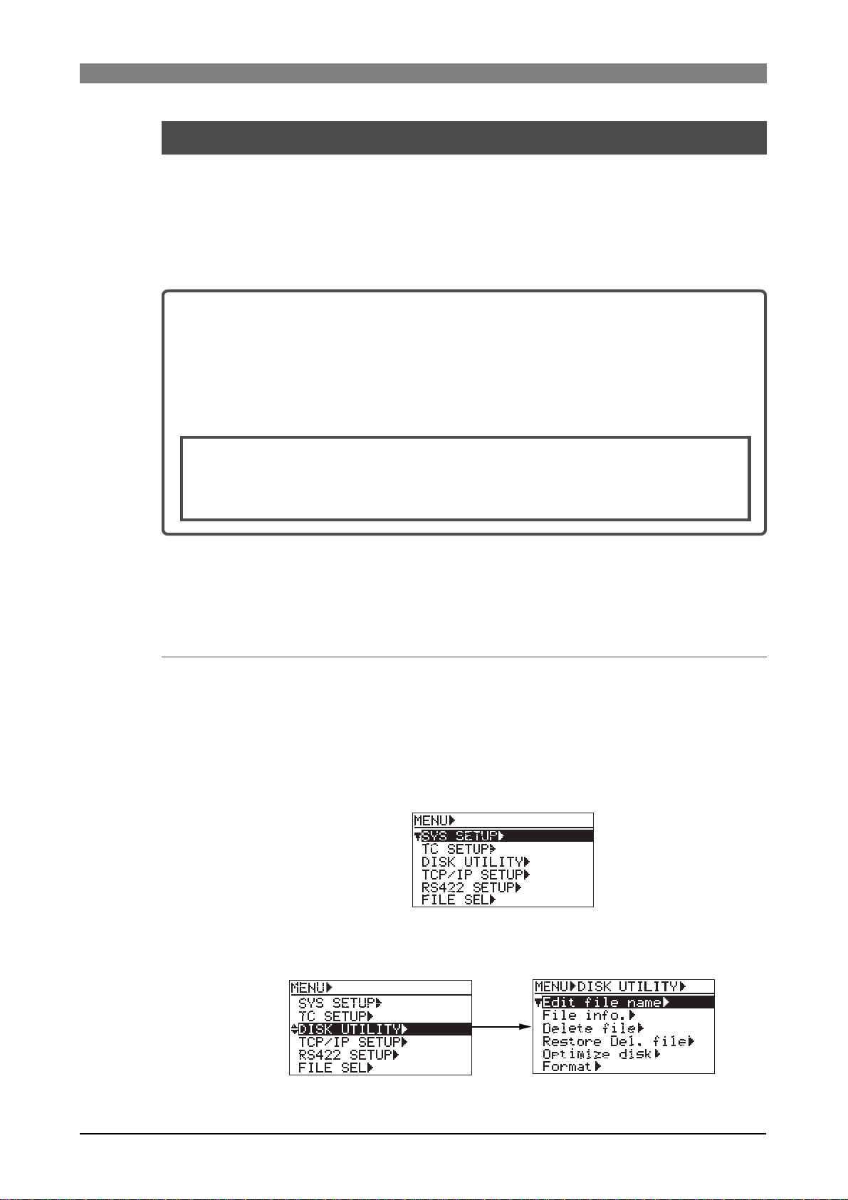
DVD Multitrack Recorder DV824DVD Multitrack Recorder DV824
DVD Multitrack Recorder DV824
DVD Multitrack Recorder DV824DVD Multitrack Recorder DV824
Dual drive recording (the optional Model 9057 required)
Dual drive recording is a special function which simultaneously records the same
data to a "mirror" DVD-RAM disk (*) while recording audio data to a hard disk partition specially formatted for "dual drive recording".
Dual drive recording intends to make a clone disk.
Therefore, editing meta data or disk volume label (reel No.) of an audio file recorded
to a hard disk partition is reflected to a "mirror" DVD-RAM disk.
(*) About "mirror" disk
A DVD-RAM disk which is the partner of the current drive formatted for "dual
drive recording" is called a "mirror disk".
When formatting the DV824 internal hard disk partition for "dual drive recording", a DVD-RAM disc set to the DVD-RAM drive is automatically assigned as a
"mirror disk". Therefore, when making dual drive recording, the "mirror disk"
must be set to the drive.
<Note>:
To make it possible to record data only to the mirror disk, reformat the current hard
disk partition for normal recording via the "Format" menu item in the "DISC UTILITY" menu of the MENU mode.
The following explains how to format a partition for dual drive recording and how to
make dual drive recording.
You cannot record data only to the mirror disk.
Formatting in the "DDR" mode
To carry out dual drive recording, you have to format the current partition in the
"DDR" mode for dual drive recording. The following procedure is assumed that the
"PT02HD" hard disk partition is currently selected (see page 83 for details about how
to select a partition).
1) While the unit is stopped, press the [ENTER/YES] key to enter the MENU mode.
The display now shows the MENU list screen.
2) Use the [MENU] dial to select "DISK UTILITY" and press the [ENTER/YES] key.
The display now shows the DISK UTILITY menu screen.
89
Page 90

DVD Multitrack Recorder DV824DVD Multitrack Recorder DV824
DVD Multitrack Recorder DV824
DVD Multitrack Recorder DV824DVD Multitrack Recorder DV824
3) Use the [MENU] dial to select "Format" and press the [ENTER/YES] key.
The display now shows the screen for format setting.
We assume to use the default reel number (volume label) which is "S003", and
skip to the format mode selection.
(If you want to change the reel number later, you can do it using the "Reel No"
menu item in the "DISK UTILITY" menu of the MENU mode.)
4) Use the [MENU] dial to select "Format Mode" and press the [ENTER/YES] key.
The current format mode ("Normal" on the screen below) flashes. You can now
select the desired mode.
5) Use the [MENU] dial to select "DDR" and press the [ENTER/YES] key.
The format mode is set to "DDR" and "EXECUTE" is highlighted.
6) While "EXECUTE" is highlighted, press the [ENTER/YES] key.
The display shows the caution message before executing formatting.
As this caution message tells you, if you format partition 2 (PT02) in the "DDR"
mode, the DVD-RAM disk which is assigned as a "mirror disk" is also formatted
and all data on the DVD-RAM disk and partition 2 are erased.
7) If you are sure, press the [ENTER/YES] ke y to e x ecute f ormatting.
The display now shows the formatting progress indication. When formatting
completes, "Fmt.Completed!" is shown.
90
Page 91

DVD Multitrack Recorder DV824DVD Multitrack Recorder DV824
DVD Multitrack Recorder DV824
DVD Multitrack Recorder DV824DVD Multitrack Recorder DV824
8) Press the [STOP/HOME] key to e xit the MENU mode.
After exiting the MENU mode, the display returns to the Home screen of the
current partition, while the DV824 scans the mirror disk.
On the Home screen, you can see " " beside the name of the partition, as
shown below.
Now you are ready for dual drive recording.
Making dual drive recording
The following procedure is assumed that the selected partition (PT02) is "DDR" formatted and a mirror disk is set to the DVD-RAM drive.
<Note>:
drive. If a wrong disk is set to the DVD-RAM disk drive or no disk is set, the DV824 detects
an error when scanning the mirror disk, and shows a caution message ("Difference! DDR
mirror disk", etc.). When it scans a correct mirror disk, "Presence! DDR mirror disk" is
shown.
<Note>:
switch to a "DDR" formatted hard disk partition and set a mirror disk to the DVD-RAM
drive.
On the screen for selecting a drive, "DDR" is placed on the right of the name of the "DDR"
formatted partition. So you can easily distinguish them.
To execute dual drive recording, you must set a mirror disk to the DVD-RAM disk
When starting dual drive recording, if the current drive is "Normal" formatted,
1) Start recording to partition 2 ("PTO2").
Dual drive recording starts. The DV824 also make recording to the mirror disk in
the background, as well as recording to partition 2 ("PTO2").
2) After completing recording, press the [STOP/HOME] key to stop recording.
If recording has not been successfully made, immediately cancel by the False start
function and make recording again.
91
Page 92
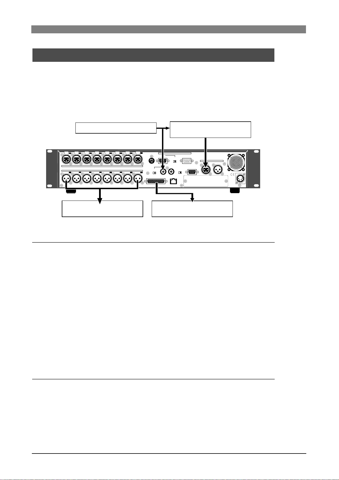
DVD Multitrack Recorder DV824DVD Multitrack Recorder DV824
DVD Multitrack Recorder DV824
DVD Multitrack Recorder DV824DVD Multitrack Recorder DV824
Chasing external TC (the optional Model 8348 required)
The following explains how to chase-sync the unit to time code received from the
[TIME CODE INPUT] connector when the optional TC/SYNC card (Model 8348) is
installed.
In the following connection example, a VTR is a master, while the DV824 (with the
Model 8348) is a slave. The DV824 receives time code recorded on the master VTR
and chase the master. A word sync reference signal is also fed to the DV824 from the
master VTR.
HOUSE SYNC
Video Sync signal
PARALLEL
7
8
1:GND 2:HOT 3:COLD
876
6
ANALOG INPUT BALANCED [+4dBu]
ANALOG OUTPUT BALANCED [+4dBu]
543
Analog mixer
1
2345
21
or
REMOTE
ON
75Ω
DIGITAL I/O
OFF
INPUT
WORD
INPUT
P2/ES BUSS
THRU
100Ω
ON OFF
WORD
OUTPUT
LEVEL SEL
24V5V
ETHERNET
LINKTX/RX
Digital mixer
BI-PHASE INPUT
Preparations
Before performing the chase function, set the following.
1) Set the system clock reference to "Video".
You can set the system clock reference via the quick setup mode or the "Sync
clock" menu item in the "TC SETUP" menu of the MENU mode (see pages 47 and
127).
VTR
Time code
TIME CODE
INPUT
OUTPUT
DC-IN 12V
1:GND
2:NC
3:NC
4:12V
2) Set the chase mode appropriately.
You can set the chase mode via the "Chase mode" menu item in the "TC SETUP"
menu of the MENU mode (see page 135). Three chase modes ("Once", "Continue"
and "Frame sync") are available. The default is "Once".
3) Set chase offset if required.
By setting chase offset appropriately, the unit chases and locks to the master with
maintaining a time interval.
You can set chase offset via the "Chase offset" menu item in the "TC SETUP" menu
of the MENU mode (see page 136).
Chasing
1) Starts playback of the master (in this example, VTR).
2) Press the DV824 [CHASE] key to activ ate the chase mode (the [CHASE] indicator
starts flashing).
The DV824 chases the master time code. When lock is achieved, it starts playback
while the [CHASE] indicator is lit steadily.
3) T o stop c hasing, press the [CHASE] key again (the [CHASE] indicator turns off).
92
Page 93

DVD Multitrack Recorder DV824DVD Multitrack Recorder DV824
DVD Multitrack Recorder DV824
DVD Multitrack Recorder DV824DVD Multitrack Recorder DV824
Data export to PC (the optional Model 8370 required)
By installing the optional IEEE1394/USB card (Model 8370) and connecting the DV824
to a personal computer via the [IEEE1394] (or [USB]) connector, audio file data can
be transferred between the DV824 and a personal computer.
DV824 audio data can be copied to a hard disk on the personal computer, or exported to a software application such as Digidesign Pro Tools.
PARALLEL
7
8
1:GND 2:HOT 3:COLD
876
6
ANALOG INPUT BALANCED [+4dBu]
ANALOG OUTPUT BALANCED [+4dBu]
543
1
2345
21
P2/ES BUSS
REMOTE
75‰
ON
OFF
DIGITAL I/O
THRU
INPUT
100‰
ON OFF
WORD
WORD
INPUT
OUTPUT
LEVEL SEL
24V5V
ETHERNET
LINKTX/RX
BI-PHASE INPUT
TIME CODE
INPUT
OUTPUT
DC-IN 12V
USB
1:GND
IEEE
1394
2:NC
3:NC
4:12V
Personal computer
<Note>:
The optional IEEE1394/USB card
To export audio file data to your PC, install the dedicated driver (on the CDROM) supplied with the optional IEEE1394/USB card or a commercially available DVDRAM writing software application to your PC.
Also note that even if appropriate writing software is correctly installed, the read/write
functions are limited depending on OS, as below.
When connecting via the [USB] port:
• Windo ws XP, Windows 2000
Both "Read" and "Write" are possible (when the supplied driver is used).
• Macintosh OSX, OS9.2.1, OS9.2.2
Only "Read" is possible (when the supplied driver or a commercially available
writing software is not used).
When connecting via the [IEEE1394] port:
• Windo ws XP, Windows 2000, Windows ME, Windo ws 98SE
Both "Read" and "Write" are possible (when the supplied driver is used).
• Macintosh OS9.2.1, OS9.2.2
Both "Read" and "Write" are possible (when the supplied driver or a commercially
available writing software is not used).
* All company names and model names mentioned in this manual are trademarks or
registered trademarks of their respective holders.
<Note>:
By installing the optional IEEE1394/USB card, the "IEEE1394" menu item is added
to the "SYS SETUP" menu of the MENU mode.
Added
93
Page 94

DVD Multitrack Recorder DV824DVD Multitrack Recorder DV824
DVD Multitrack Recorder DV824
DVD Multitrack Recorder DV824DVD Multitrack Recorder DV824
Connecting PC to the unit
After connecting the cable between the unit and a PC, make the setting below while
the PC is on.
<Note>:
unit and an audio file is loaded.
If no disk is set, you cannot make the "IEEE1394" menu setting in the "SYS SETUP" menu.
In the following operation, we assume that a recorded DVD-RAM disk is set to the
1) Set the "IEEE1394" menu item in the "SYS SETUP" menu of the MENU mode to
"CONNECT".
How to unmount the D V824 fr om the PC
To unmount the DV824 from the PC, make the PC side ready for unmounting the
DV824, disconnect the IEEE1394 cable, and set the "IEEE1394" menu item to "DISCONNECT".
Depending on the PC, the method for making the PC ready for unmounting the DV824
differs. Please refer to the instructions of the PC.
<Note>:
Therefore, to stop using IEEE1394, disconnect the cable immediately after unmounting the
unit.
<Note>:
mounted to your PC. To transfer files between the Model 9057 and the PC, use the Ethernet
function (
Depending on the OS, the unmounted device may be immediately mounted again.
You can mount only the DVD-RAM drive. The optional Model 9057 cannot be
see page 73
).
Example of copying data to a computer hard disk
In the following procedure, we assume that the cable between the DV824 and the PC
is connected and the "IEEE1394" menu item in the "SYS SETUP" menu of the MENU
mode is set to "CONNECT".
<Note>:
DV824 panel are disabled.
When the "IEEE1394" menu item is set to "CONNECT", the keys and dial on the
1) Make sure that the DV824 icon appears on the desktop of y our computer (note
that the icon looks differently depending on the personal computer).
2) Start up an appropriate application such as Explorer on the computer , and copy
an audio data file in the DV824 drive to the computer hard disk.
94
Page 95

DVD Multitrack Recorder DV824DVD Multitrack Recorder DV824
DVD Multitrack Recorder DV824
DVD Multitrack Recorder DV824DVD Multitrack Recorder DV824
Example of exporting data to a computer application
The procedure example below shows how to export DV824 data to Digidesign Pro
Tools for Macintosh. For details about operations of Pro Tools, see the instructions
supplied with Pro Tools. Note that the screen examples below may look different
from the screen you actually see. Also note that the procedure below is assumed that
the DV824 is connected to the PC and the "IEEE1394" menu in the Utility mode is set
to "CONNECT".
1) Start up the application software (Pro Tools, in this example).
2) Click on "Audio" on the Pr o T ools screen to pop up the audio region list menu
(indicated by an arrow 1).
3) Select and click on the "Import Audio" menu fr om the popup men u (indicated b y
an arrow 2).
1
2
Import Audio
Select and click on
“Import Audio”.
Audio
Click on “Audio”.
4) Select and click on "D V824-DVD" (or "S001") on the desktop (indicated by an
arrow 3).
The disk volume label example shown below is a default tentative name.
If you have edited the volume name (Reel No.) in the disk formatting process, the
edited name is shown.
DV824-DVD
3
Select and click on
“DV824-DVD” on the desktop.
5) Select and click on an audio file in the "bwff" directory on the disk (indicated b y
an arrow 4).
The selected audio file is shown in "Region in current file".
6) Click on "Con vert ->", followed by "Done" (indicated by an arrow 5).
The display shows the window for saving a file.
95
Page 96

DVD Multitrack Recorder DV824DVD Multitrack Recorder DV824
DVD Multitrack Recorder DV824
DVD Multitrack Recorder DV824DVD Multitrack Recorder DV824
4
bwff
Select “bwff”.
The selected
audio file is shown.
7) Select a saving file and click on "Select" (indicated by an arrow 6).
The computer starts saving the file to the selected file.
Click on “Convert->”.
Convert->
5
Done
5
Click on “Done”.
6
Select
Click on “Select”.
The saved file is added to the audio region list (indicated by an arrow 7).
7
The saved file is shown.
96
Page 97

DVD Multitrack Recorder DV824DVD Multitrack Recorder DV824
DVD Multitrack Recorder DV824
DVD Multitrack Recorder DV824DVD Multitrack Recorder DV824
8) After making "Spot" active, drag and drop the audio region list to the track area
(indicated by an arrow 8).
The "Spot Dialog" setting window appears.
8
Spot
The Spot Dialog window appears.
9) Click on " " in the "Spot Dialog" setting window, follo wed by "OK" (indicated b y
an arrow 9).
By clicking on " " , the "original time stamp" time currently shown is set to the
"Start" time. Then clicking on "OK" starts importing audio data from the specified
position.
9
Click on “OK”.
The currently displayed time
of “Original Time Stamp” is
set to the “Start time”.
Click on “ ”.
9
The audio data is
imported to the specified
position.
97
Page 98

DVD Multitrack Recorder DV824DVD Multitrack Recorder DV824
DVD Multitrack Recorder DV824
DVD Multitrack Recorder DV824DVD Multitrack Recorder DV824
98
Page 99

DVD Multitrack Recorder DV824DVD Multitrack Recorder DV824
DVD Multitrack Recorder DV824
DVD Multitrack Recorder DV824DVD Multitrack Recorder DV824
Chapter-7: Creating and editing ALE files (EDIT EDL FILE menu)
This chapter describes details about how to create an ALE (Avid Log Exchange) file for exporting
audio data of the DV824 to an AVID system, as well as how to edit an existing ALE file.
Table of contents
Creating a new ALE file ................................................................................................100
Adding audio file entries to an ALE file ......................................................................103
Viewing and editing audio file entries ........................................................................105
Viewing audio file entries ............................................................................................105
Adding an audio file entry to an existing ALE file ....................................................106
Deleting an audio file entry .........................................................................................106
Editing an ALE file ........................................................................................................107
Editing an ALE file name ..............................................................................................107
Remaking an ALE file ....................................................................................................108
Deleting an ALE file .......................................................................................................109
99
Page 100

DVD Multitrack Recorder DV824DVD Multitrack Recorder DV824
DVD Multitrack Recorder DV824
DVD Multitrack Recorder DV824DVD Multitrack Recorder DV824
On a DVD-RAM disk, the DV824 creates the "info" folder under the "bwff" folder. The
"Info" folder stores ALE (Avid Log Exchange) files and various information files such
as a diagnoses file.
About an ALE file
An ALE file is an EDL (Edit Decision List) file for exporting audio data created by the DV824
to an AVID system. Because it is a text file, a personal computer easily reads it.
Note that the start and end time values of the file are referenced to the BWF time reference
and data length. The ALE file is also used for the DV824 list play function.
DVD RAM disk
Resume. rsm
BWFF
*****.wav
*****.wav
*****.wav
INFO
*****.ale
*****.ale
Creating a new ALE file
You can create a new ALE file on a recorded DVD-RAM disk.
In the procedure described below, we assume that more than one audio file (BWF) is
created on the DVD-RAM disk set to the DV824.
1) While the unit is stopped, press the [SHIFT] key to light the [SHIFT] indicator, followed by
the [LIST PLAY/
The unit enters the "EDIT EDL FILE" menu and the display now shows the ALE screen for
selecting an ALE file.
<Note>:
example above. If any ALE file exists on a disk, its current file name is shown.
<Note>:
below.
• Press the [ENTER/YES] key to enter the MENU mode.
• Use the [MENU] dial to highlight "EDIT EDL FILE" and press the [ENTER/YES] key.
EDIT EDL
] key.
If no ALE file exists on the disk, only "<New file>" is shown as the screen
You can also enter the "EDIT EDL FILE" menu by following the procedure
100
 Loading...