

Page 1
8288 486 000
DVD Master Recorder
Model
Operation Manual
Page 2
CAUTION
RISK OF ELECTRIC SHOCK
DO NOT OPEN
CAUTION: TO REDUCE THE RISK OF ELECTRIC SHOCK,
DO NOT REMOVE COVER (OR BACK).
NO USER - SERVICEABLE PARTS INSIDE.
REFER SERVICING TO QUALIFIED SERVICE PERSONNEL.
"WARNING"
"TO REDUCE THE RISK OF FIRE OR ELECTRIC SHOCK,
DO NOT EXPOSE THIS APPLIANCE TO RAIN OR
MOISTURE."
CAUTION:
TO PREVENT ELECTRIC SHOCK, MATCH WIDE BLADE OF
PLUG TO WIDE SLOT, FULLY INSERT.
ATTENTION:
POUR EVITER LES CHOCS ELECTRIQUES, INTRODUIRE
LA LAME LA PLUS LARGE DE LA FICHE DANS LA BORNE
CORRESPONDANTE DE LA PRISE ET POUSSER JUSQU'
AU FOND.
The lightning flash with arrowhead symbol, within an equilateral
triangle, is intended to alert the user to the presence of
uninsulated "dangerous voltage" within the product's enclosure
that may be of sufficient magnitude to constitute a risk of electric
shock to persons.
The exclamation point within an equilateral triangle is intended
to alert the user to the presence of important operating and
maintenance (servicing) instructions in the literature
accompanying the appliance.
SAFETY INSTRUCTIONS
1. Read Instructions - All the safety and operating instructions
should be read before the appliance is operated.
2. Retain Instructions - The safety and operating instructions
should be retained for future reference.
3. Heed Warnings - All warnings on the appliance and in the
operating instructions should be adhered to.
4. Follow Instructions - All operating and use instructions should
be followed.
5. Water and Moisture - The appliance should not be used near
water - for example, near a bathtub, washbowl, kitchen sink,
laundry tub, in a wet basement, or near a swimming pool, and
the like.
6. Carts and Stands - The appliance should be used only with a
cart or stand that is recommended by the manufacturer.
An appliance and cart combination should be moved with care.
Quick stops, excessive force, and uneven surfaces may cause
the appliance and cart combination to overturn.
7. Wall or Ceiling Mounting - The appliance should be mounted to
a wall or ceiling only as recommended by the manufacturer.
8. Ventilation - The appliance should be situated so that its location
or position dose not interfere with its proper ventilation.
For example, the appliance should not be situated on a bed,
sofa, rug, or similar surface that may block the ventilation
openings; or, placed in a built-in installation, such as a bookcase
or cabinet that may impede the flow of air through the ventilation
openings.
9. Heat - The appliance should be situated away from heat sources
such as radiators, heat registers, stoves, or other appliances
(including amplifiers) that produce heat.
10. Power Sources - The appliance should be connected to a power
supply only of the type described in the operating instructions or
as marked on the appliance.
11. Grounding or Polarization - The precautions that should be taken
so that the grounding or polarization means of an appliance is
not defeated.
12. Power Cord Protection - Power supply cords should be routed
so that they are not likely to be walked on or pinched by items
placed upon or against them, paying particular attention to cords
at plugs, convenience receptacles, and the point where they
exit from the appliance.
13. Cleaning - The appliance should be cleaned only as
recommended by the manufacturer.
14. Nonuse Periods - The power cord of the appliance should be
unplugged from the outlet when left unused for a long period of
time.
15. Object and Liquid Entry - Care should be taken so that objects
do not fall and liquids are not spilled into the enclosure through
openings.
16. Damage Requiring Service - The appliance should be serviced
by qualified service personnel when:
A. The power supply cord or the plug has been damaged; or
B. Objects have fallen, or liquid has been spilled into the appliance; or
C. The appliance has been exposed to rain; or
D. The appliance does not appear to operate normally or
exhibits a marked change in performance; or
E. The appliance has been dropped, or the enclosure damaged.
17. Servicing - The user should not attempt to service the appliance
beyond that described in the operating instructions.
All other servicing should be referred to qualified service
personnel.
2
Page 3

Table of Contents
About this manual ........................................................................................................8
Manual construction ........................................................................................................8
Precautions ................................................................................................................10
Precautions on installation ...........................................................................................10
Precautions on safety ....................................................................................................10
DV40 main features ....................................................................................................11
Chapter-1: Before using the DV40
Turning on the power ............................................................................................1-2
Setting the internal clock ......................................................................................1-3
Loading a DVD-RAM disk ......................................................................................1-4
Formatting a DVD-RAM disk .................................................................................1-5
About audio files on a formatted disk ..................................................................1-7
About REMAIN display ..........................................................................................1-8
Chapter-2: Names of Functions
Front panel part 1 ..................................................................................................2-3
Front panel part 2 ..................................................................................................2-6
FL display ................................................................................................................2-11
Front panel part 3 .................................................................................................2-12
Rear panel ...............................................................................................................2-14
Chapter-3: Reformatting/optimizing a DVD-RAM disk
Reformatting a DVD-RAM disk .............................................................................3-2
Optimizing a disk ...................................................................................................3-5
Chapter-4: Recording/Playback the audio signal
About the expression for audio files in this manual ...........................................4-2
About the NEW FILE and INSERT mode ................................................................4-2
Recording an analog source in the NEW FILE mode ............................................4-3
Preparation ....................................................................................................4-3
Preparation for recording ............................................................................4-4
Recording .......................................................................................................4-5
Playback of recorded audio ..................................................................................4-6
You can create an audio file before recording .....................................................4-6
Recording an analog source in the INSERT mode ................................................4-7
Preparation for recording ............................................................................4-7
Recording .......................................................................................................4-7
Multiple-undo function .........................................................................................4-8
Selecting a desired file on a disk ...........................................................................4-9
3
Page 4

Recording to a “Tape mode” audio file in the INSERT mode ............................4-10
Creating a “Normal mode” audio file on a disk formatted in the Tape mode .4-11
Recording a digital source in the NEW FILE mode .............................................4-12
Preparation ....................................................................................................4-12
Preparation for recording ...........................................................................4-13
Recording .......................................................................................................4-13
Recording a digital source in the INSERT mode ................................................4-14
Preparation for recording ...........................................................................4-14
Recording .......................................................................................................4-14
MUTE recording .....................................................................................................4-15
Slate tone function ................................................................................................4-16
Cueing by the jog function ..................................................................................4-17
Cueing/high speed shuttle by the shuttle function ..........................................4-17
Chapter-5: Time code recording
Time code recording ..............................................................................................5-2
Selecting the recording mode ......................................................................5-2
Selecting source time code ..........................................................................5-2
Recording time code generated by the internal time code generator ..............5-3
Settings of the DV40 .....................................................................................5-3
Recording external time code ...............................................................................5-4
Connection to external devices/Setting of the DV40 ................................5-4
TC Setup mode details ...........................................................................................5-5
To enter the TC Setup mode ........................................................................5-5
Setting the internal TC generator start time ..............................................5-6
Force-jamming to external time code .........................................................5-6
Selecting output time code ..........................................................................5-7
Editing the chase offset ................................................................................5-7
Trimming the chase offset ...........................................................................5-8
Editing the LTC start time ............................................................................5-8
Catch offset ....................................................................................................5-9
Chase mode selection ...................................................................................5-9
Chapter-6: Storing time data
Location memory keys ..........................................................................................6-2
Storing a time to an edit point memory ...............................................................6-3
Capturing a time “on the fly” ......................................................................6-3
Storing a time to an edit point using the numeric keys ............................6-4
Storing a time to locate memory (CUE/MEMORY) ..............................................6-5
Storing a time to a locate point memory
(CUE or MEMORY point memory) “on the fly” ..................................6-6
Storing a time to a locate point using the numeric keys ...........................6-7
Editing a name of CUE or MEMORY point .............................................................6-8
Clearing a CUE or MEMORY point memory ..........................................................6-9
4
Page 5

Chapter-7: Locate Function
A variety of locate functions .................................................................................7-2
Location to the beginning (ABS 0) of an audio file ....................................7-2
Location to the end (REC END) of the current audio file ..........................7-2
Location to the last playback start position ...............................................7-3
Location to the last recording start position ..............................................7-3
Location to the last recording end position ...............................................7-3
Location to the point where the recorder located last time ......................7-4
Location to an audio file edit point .............................................................7-4
Location to a CUE point ................................................................................7-4
Location to a MEMORY point .......................................................................7-5
Location to the next or previous
CUE/MEMORY point using the skip mode (Skip locate function) ...7-5
Chapter-8: Preview Function
Preview at an edit point .........................................................................................8-2
Preview at a locate point .......................................................................................8-3
Trimming while previewing audio .......................................................................8-4
Chapter-9: Audio file management
Creating a new audio file .......................................................................................9-2
Creating a new file on a disk just after formatted in the Normal mode ..9-2
Creating a new file on a disk just after formatted in the Tape mode ......9-3
Selecting an audio file ...........................................................................................9-4
Selecting a file using the file select function ..............................................9-4
Selecting a file using the skip function .......................................................9-4
Editing an audio file name ....................................................................................9-5
Deleting an audio file ............................................................................................9-6
Restoring a deleted audio file ...............................................................................9-7
Duplicating an audio file .......................................................................................9-8
Chapter-10: Editing track data
Pasting track data ................................................................................................10-2
Inserting track data .............................................................................................10-4
Erasing track data ................................................................................................10-6
Cutting track data ................................................................................................10-8
Chapter-11: LIST PLAY function
LIST PLAY function ..............................................................................................11-2
Turning on List Play mode ..................................................................................11-3
Reprogramming Play List ....................................................................................11-4
Locating to Beginning of Play List .......................................................................11-4
Locating to End of Play List .................................................................................11-4
5
Page 6

Chapter-12: Using a PS/2 keyboard
Controlling the DV40 from a PS/2 keyboard ....................................................12-2
Ineffective keys ....................................................................................................12-2
The common functions between keys on the DV40 and a PS/2 keyboard .....12-3
Accessing setting menus using the [Alt] key .....................................................12-3
Chapter-13: FTP server function
FTP server function .............................................................................................13-2
Connection ...................................................................................................13-2
FTP command compliance ........................................................................13-3
Server file location .....................................................................................13-3
FTP client application ................................................................................13-3
Checking TCP/IP menus ............................................................................13-4
Changing the TCP/IP setting .....................................................................13-5
IP Address ..........................................................................................13-5
Gateway ...............................................................................................13-5
Sub net ...............................................................................................13-6
Login name (Administrator) ............................................................13-6
MAC Address ......................................................................................13-7
Chapter-14: Importing an audio file to a computer
Importing an audio file to the Digidesign Pro Tools .........................................14-2
Chapter-15: Setup mode
How to access and set a Setup menu ..................................................................15-2
Display contrast setting ......................................................................................15-3
Reference level setting ........................................................................................15-3
Digital input track selection ...............................................................................15-3
Digital output signal format selection ...............................................................15-3
Skipped item selection for the skip mode ..........................................................15-4
Auto EE mode On/Off ..........................................................................................15-4
Self diagnoses On/Off ..........................................................................................15-4
Panel lock On/Off ................................................................................................15-5
Setting RS-422 ......................................................................................................15-5
1. Device code setting ................................................................................15-5
2. Sync play On/Off setting .......................................................................15-5
3. Editor preset setting ...............................................................................15-5
Peak hold time setting .........................................................................................15-6
GPI On/Off setting ...............................................................................................15-6
Slate tone recording time ....................................................................................15-6
Mute recording time ............................................................................................15-6
File name mode setting .......................................................................................15-7
Default file name setting .....................................................................................15-7
Setting a file name and take number ........................................................15-7
Save/load of setup data ......................................................................................15-8
Saving setup data .......................................................................................15-8
6
Page 7

Loading setup data .....................................................................................15-9
TCP/IP settings .....................................................................................................15-10
Showing the IP address .............................................................................15-10
Setting the IP address ................................................................................15-10
Showing and setting the router IP address .............................................15-11
Showing and setting the subnet mask ....................................................15-11
Login name/password settings .................................................................15-12
Showing the MAC address ........................................................................15-13
Showing the main software version .................................................................15-13
Showing the ethernet software version ...........................................................15-13
Chapter-16: Utility mode
How to select a Utility menu ...............................................................................16-2
Selecting Rec Protect On or Off..................................................................16-2
Renumbering CUE points ...........................................................................16-3
Releasing undo files ...................................................................................16-3
Selecting On or Off of the resume function ..............................................16-4
Editing a volume name ..............................................................................16-4
Setting user bit data ...................................................................................16-5
Chapter-17: Specifications
7
Page 8

About this manual
This manual is intended to be used as a guide for using the Fostex DV40, a DVD master
recorder.
It is divided into Chapters. Each Chapter covers instructions for a specific subject or
feature of the DV40 which you should know for using the unit, as well as safety
instructions, precautions, etc. Please retain this manual at hand so that you can read it
whenever necessary.
<Manual construction>
The following shows a brief description of each chapter though you may know the
contents of each chapter by the "Table of Contents".
Chapter 1: Bef ore using the DV40
Before using the DV40, you must carry out some preparations. This chapter describes
how to set the internal clock, as well as details about formatting a DVD-RAM disk,
including UDF format details, format modes ("Normal mode" and "T ape mode") and
audio file types ("BWF" and "SDII").
Read this chapter first before using the DV40.
Chapter 2: Names of Functions
This chapter describes names and functions of keys and controls on the front panel, as
well as those of connectors on the rear panel.
If you are familiar with digital equipment, you may roughly understand the functions
the DV40 offers.
Chapter 3: Ref ormatting/optimizing a DVD-RAM disk
This chapter describes how to reformat a DVD-RAM disk and how to optimize a disk.
To format a new disk, see Chapter 1.
Chapter 4: Recor ding/pla ybac k the audio signal
This chapter describes audio recording/playback (for both analog and digital) using the
DV40. Two recording modes, "NEW FILE" and "INSERT" modes, are available. You can
choose the appropriate mode depending on the situation.
You can also find description about mute recording, slate tone recording, cueing by the
jog/shuttle mode, etc.
Chapter 5: Time code recording
This chapter describes how to record SMPTE/EBU time code to the DV40, as well as the
TC Setup mode which provides preferences/settings for time code recording/playback.
Read this chapter when carrying out the operations for internal time code generator
setting, force-jamming to an external time code, chase offset to an external time code,
etc.
Chapter 6: Storing time data
This chapter describes how to store time data to location memories (CUE and MEMORY
points). It also describes how to erase or edit time data.
Chapter 7: Locate Function
This chapter describes various locate functions including direct location to the
beginning or end of an audio file, location to a “CUE” or “MEMORY” point, etc.
8
Page 9

Chapter 8: Previe w Function
This chapter describes the fade-in/fade-out preview (point rehearsal) function at an
edit/CUE/MEMORY point. It also describes how to trim the point while previewing.
Chapter 9: A udio file mana gement
This chapter describes the management of audio files ("BWF" and "SDII") created on
a DVD-RAM disk. It includes details about how to create a new audio file, select an
audio file, edit a file name, and delete/copy an audio file.
Chapter 10: Editing trac k data
This chapter describes how to edit track data using the paste, insert, cut and erase
functions.
Chapter 11: List pla y function
This chapter describes the list play function. This function allows you to play back
more than one recorded track continuously in order of file number or by assigning
files at appropriate LTC positions.
Chapter 12: Using a PS/2 ke yboar d
This chapter describes how to control the DV40 using a PS/2 keyboard connected to
the [KEYBOARD] terminal. You can edit a file name or volume label by a PS/2 key
board.
Chapter 13: FTP server function
This chapter describes the FTP (File Transport Protocol) server function of the ETHER
card mounted on the DV40. The ETHER card can be used as an FTP server by
connecting the ETHER connector on the DV40 rear panel to a personal computer
using a LAN cable. You can transfer an audio file between the DV40 and a personal
computer via the TCP/IP.
Chapter 14: Importing an audio file to a computer
This chapter describes how to import an audio file created by the DV40 to a
computer software (Digidesign Pro Tools).
Chapter 15: Setup mode
This chapter describes details about the menu in the Setup mode. You can set
preferences, etc. of the DV40.
Chapter 16: Utility mode
This chapter describes the Utility mode.
This mode, as well as the Setup mode, deals with preference menus of the DV40.
9
Page 10

Precautions
<Precautions on installation>
Do not install the unit in the following conditions.
- in a extremely hot or cold place
- in a moist place
- in a dusty place
- in a strong magnetic field or near a device which generates a magnetic field
- in the direct sunshine
<Precautions on safety>
• Be sure to connect the unit to the power supply specified in the specification section of this
manual.
If you use the unit in an area with a different power voltage, first consult your dealer or the
nearest Fostex service station.
• When you unplug the power cord from AC outlet or the unit, hold the plug, to avoid
possible electric shock.
• Do not plug or unplug the power cord from or to AC outlet or the unit while your hands are
wet to avoid possible electric shock.
• Plug the power cord firmly to AC outlet and the unit.
• It is very dangerous to use a power cord that is frayed or damaged. In such a case, stop
using the unit immediately and change the cord to a new one.
• If the unit is not going to be used for a long period of time, we recommend to disconnect
the power cord form AC outlet.
• Do not let water or other liquid, or metal objects such as pins, accidentally enter the inside
of the unit (especially the inside of the tray) because this may lead to electric shock or
damage. Should water enter the inside of the unit, remove the power cord from AC outlet,
and consult your dealer or the nearest Fostex service station.
• Do not drop or the unit or give a strong shock to the unit, which may lead to damage of the
internal circuits or FL display.
10
Page 11

D V40 main features
• Using a DVD-RAM disk as a recording media, you can directly record or play back audio
data. For recording, the Verify Write recording method, with which data is always verified,
is applied, allowing the highly reliable recording.
• The most popular "UDF format" is used for the DVD-RAM disk format. Audio data recorded
to a DVD-RAM disk is stored as an "SDII" or "BWF" file in an appropriate directory ("sd2f"
for an SDII file, "bwff" for a BWF file). Therefore, two kinds of audio files can share a single
disk.
• The "T APE mode" is available, in which audio data currently being recorded is never lost
even if the unit is accidentally shut down by the power failure, etc. A very useful mode for
live recording, etc.
• Three track modes are available; mono track, stereo (2 tracks), and multitrack (4 tracks).
• The supporting sampling frequencies are 44.1 kHz, 48 kHz, 88.2 kHz, 96 kHz, 176.4 kHz
and 192 kHz. In addition, the 0.1 % pull-up/pull-down function is available.
Note: You cannot record audio data of 88.2 kHz/4-track mode, 96 kHz/4-track mode, 176.4
kHz and 192 kHz.
• Non-destructive editing (copy, paste, insert, cut and erase) for track data is possible.
• Two recording modes, "NEW FILE mode" and "INSERT mode", are available. In the "INSERT
mode", you can undo recording to go back to the desired take by selecting the date/time
when the take is executed (multiple undo function).
• Equipped with four XLR analog inputs (24 bit/192 kHz A/D) and four sets of XLR and 1/4-
inch phone analog outputs (24 bit/192 kHz AD).
• Equipped with two sets of digital inputs/outputs (AES/EBU).
• Equipped with the WORD IN and VIDEO IN connectors, allowing synchronization to a word
or video signal.
• Equipped with a 15-pin remote connector which conforms to the Sony 9-pin protocol,
allowing the unit to be controlled by an editor.
• The chase mode function allows chase-sync to external LTC.
• Built in a time code generator which supports "24H RUN", "REC RUN", "FREE RUN" and "EXT
RUN" modes.
• Supports all kinds of time code frame rates, including "23.97" for tele-cine conversion.
• The "List play" function allows continuous playback of multiple audio files in order of file
number or LTC start time.
• The comprehensive locate function allows you to locate to any of various edit points and
memory locate points.
• Precision analog scrub using a jog dial is possible.
• A PS/2 keyboard can be used for file name/label name editing.
• You can transfer an audio file on TCP/IP between the DV40 and a personal computer by
using the ETHER card as an FTP server.
• You can record a blank space or slate tone manually, or automatically by setting the
desired time range in the Setup menu.
• The file management on a VGA monitor, a waveform editing using a PS/2 keyboard,
playback of a DVD Audio disc, etc. are planned to be available by version-up or adding an
option in the future.
11
Page 12

Page 13
Chapter-1
Before using the DV40
Before using the DV40, you must carry out some preparations. This chapter describes how to set the internal clock and how to format a DVD-RAM
disk.
Page 14
Turning on the power
YMDHM
S
DATE
HMSF
4
3
2
1
-INT-
BWF
FORMAT
CLOCK
kHz
48
24
FS
BIT
PGM
LTC
∞
60
50
42 34 28 2018
12
8
6543210OL
After connecting the supplied power cord, you can turn on the power of the unit.
1. Press down the [POWER] switch.
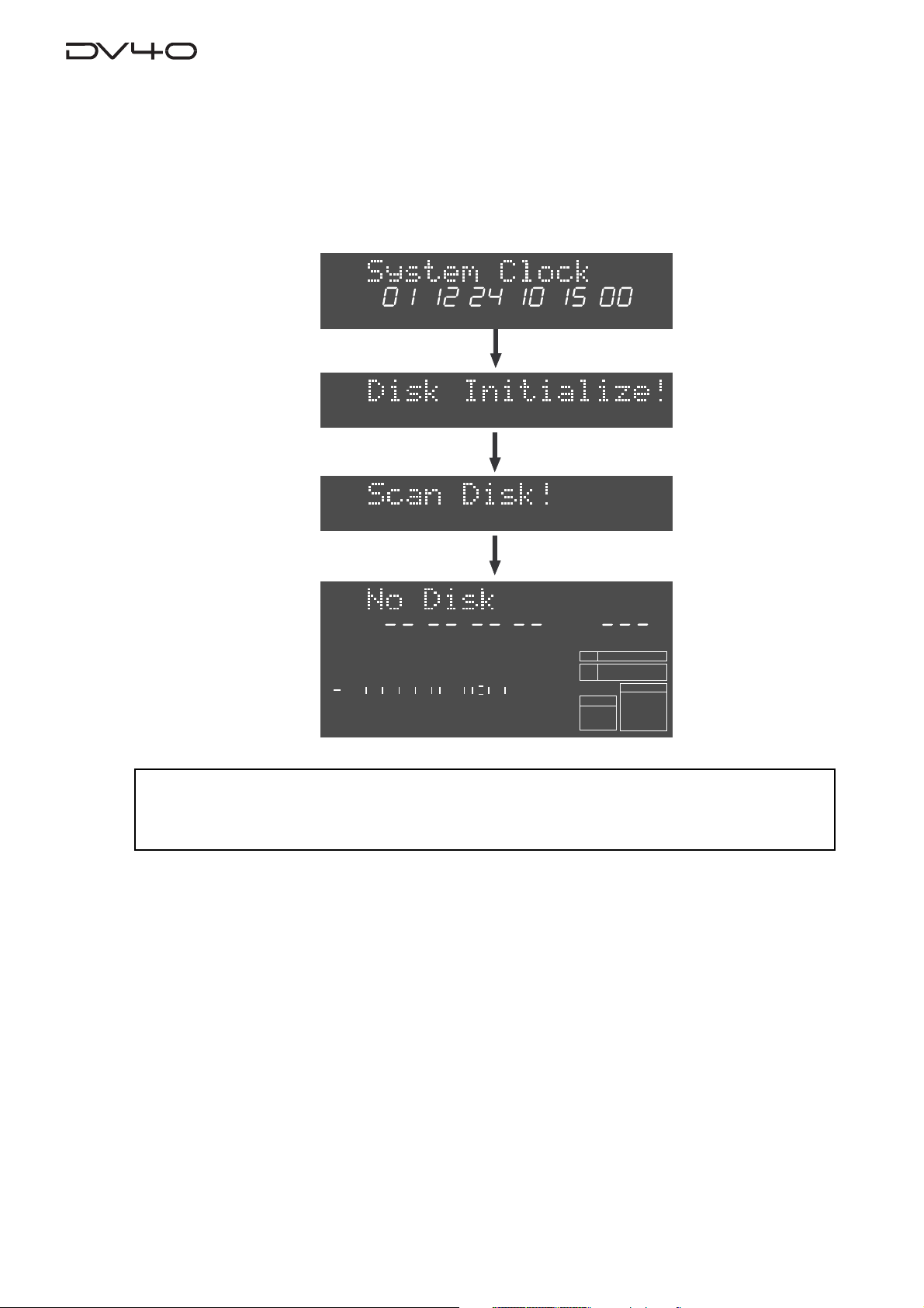
After showing the start-up display (showing the system clock, followed by "Disk Initialize!"), the unit
activates and scans the disk (showing "Scan Disk!"), then shows "No Disk".
<Note>
When turning off the power, make sure that the unit is not in the Setup mode and ceases disk
access.
1-2
Page 15

Setting the internal cloc k
HMSF
LTC
YMDHM
S
SETUP
YMDHM
S
SETUP
The internal clock is built in the unit, which is adjusted to the Japanese time when shipped.
Set the clock to your local time before using according to the following procedure.
The internal clock time is used for date information and a tentative name when creating an
audio file, as well as necessary data for executing the multiple undo function.
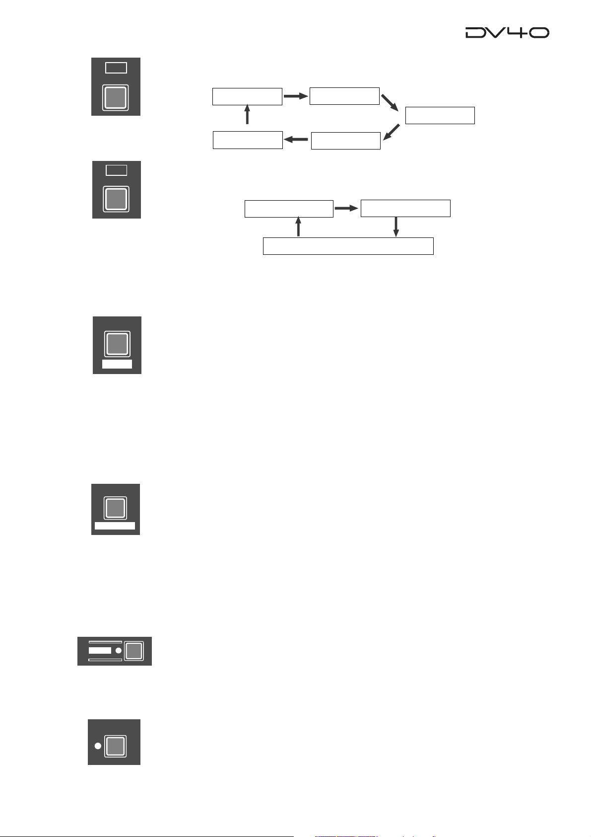
1.Press the [SETUP] key.
The display changes to the "Adjust RTC?", one of menu items in the Setup mode, from "No Disk".
The current internal clock time is shown.
Flashing
2.Press the [ENTER/YES] key.
"?" disappears while the number in the "second" digit starts flashing, showing that the date/time
value now can be edited.
Set the date/time value appropriately according to the following methods.
Flashing
• Use the [SKIP/CURSOR] I<</>>I keys to move the editing point, and use the jog dial to enter
the value.
or
• Use the numeric keys to enter the date/time value directly.
When entering data using the numeric keys, regardless of the current editing point, the value is
entered from the right-hand (second) digit which moves left as additional digits are entered.
For example, to set the clock to 3:10:00 p.m. of April 1. 2002, press the numeric keys in the
following order.
0 -> 2 -> 0 -> 4 -> 0 -> 1 -> 1 -> 5 -> 1 -> 0 -> 0 -> 0
3.Press the [ENTER/YES] key after enter the value.
The internal clock starts from the entered date/time value.
You can precisely set the clock by listening to the time signal when pressing the [ENTER/YES] key.
4.Press the [EXIT/NO] key.
The unit exits the Setup mode and the display shows "No Disk" again.
1-3
Page 16
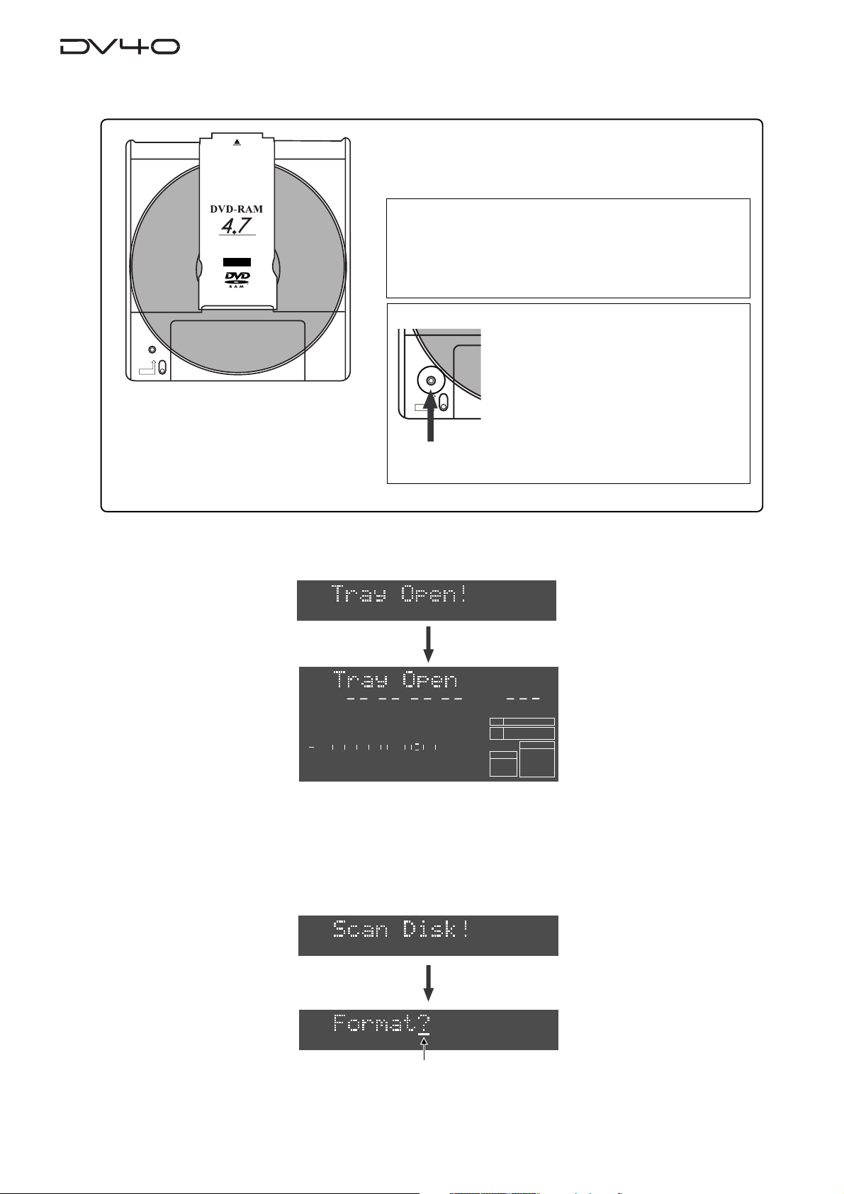
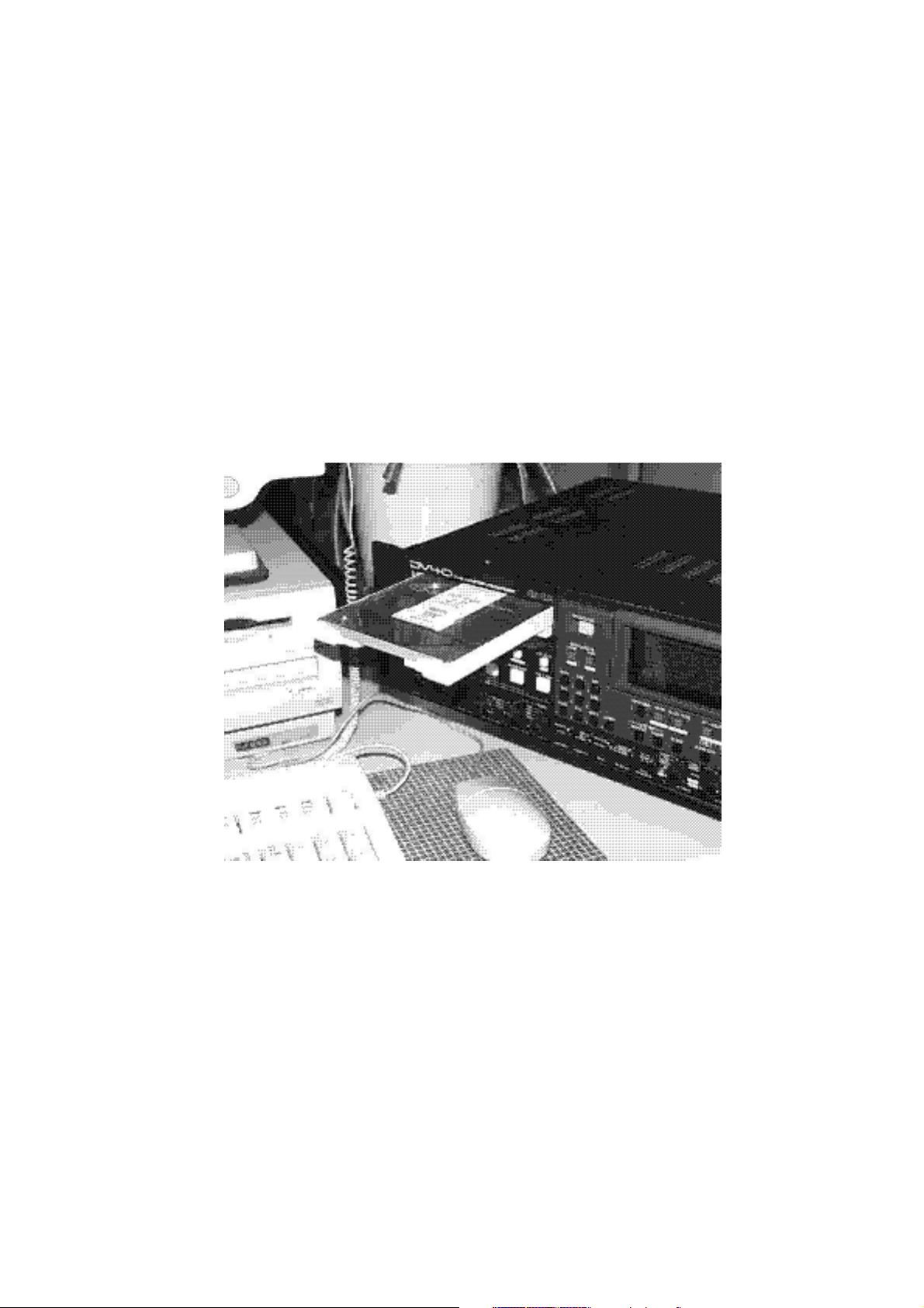
Loading a D VD-RAM disk
TYPE
2
REWRITABLE
PROTECT
About usable D VD-RAM disks
TYPE 2, one-side disks with 4.7 GB capacity can be used
with the DV40.
<Note>
Use a 4.7GB/TYPE 2 DVD-RAM disk with the DV40.
The DV40 only can play back data on a 2.6GB disk recorded
by other equipment.
Please note that the DV40 does not guarantee recording and
editing operations with a 2.6GB disk.
<Note>
Do not use a DVD-RAM disk whose tab (indicated by an allow in the figure on the left)
is removed in order to take out the disk from
the case. If you use such a disk, 2- or 4-track
PROTECT
recording with 176.4kHz/24 bit or 192kHz/
24 bit may not be properly executed. Also
note that, if you use an used DVD-RAM disk
with the DV40, we recommended to format
the disk by a computer first, then format it
by the DV40.
1.Press the [OPEN/CLOSE] key.
The display shows "T ray Open!" and the tray opens.
LTC
1
2
50
60
∞
3
4
HMSF
8
42 34 28 2018
12
PGM
6543210OL
BIT
FS
kHz
FORMAT
BWF
24
48
CLOCK
-INT-
2.Place a DVD-RAM disk in the tra y, and press the [OPEN/CLOSE] ke y a gain (or push
the front of the tray lightly).
The disk is loaded. After the unit scans the disk ("Disk Scan!" is shown as a flashing display while
scanning), it automatically recognizes that the disk is unformatted and enters the "Format" menu
("Format" with flashing "?" is shown).
Flashing
You can format the disk by the f ollowing pr ocedure in the ne xt page.
1-4
Page 17
Formatting a DVD-RAM disk
To make a DVD-RAM disk usable with the DV40, format the disk by the “UDF format”.
Two format modes, “Normal” and “T ape”, are available with this unit. Use either format
according to the situation.
<About UDF format>
The DV40 formats a disk in the UDF “R1.50” format. It can read a disk formatted in the “R1.50” or “R2.0*”
format using a personal computer without any difficulty. Note that MAC OS 9.1 supports the “R1.50” format but
does not support the “R2.0*” format. Therefore, a Macintosh computer running on MAC OS 9.1 cannot read a
disk formatted in the “R2.0*” format using a Windows 98 computer. To ensure the compatibility among the
DV40 and computers, we recommend to format a disk in the “R1.5” format if you have a Windows 98 computer.
Normal Mode
Normally, format a disk by selecting the format mode
to Normal. No audio file is automatically created when
formatting the disk in the Normal mode ("No Audio
Files!" is shown after formatting is completed).
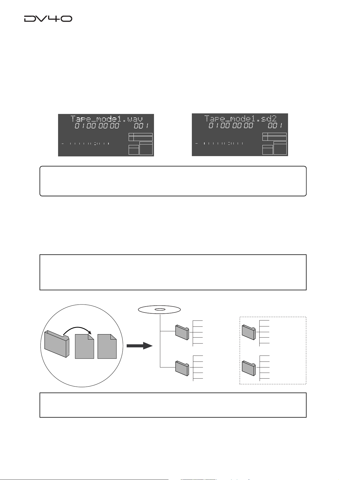
On a "Normal format" disk, a "Normal mode" audio
file ("BWF" or "SDII") is automatically created when
executing recording in the NEW FILE mode.
Or you can also create "Normal mode" audio files using the file select function before recording. Up to 200
audio files can be created.
A disk formatted in the Tape mode reserves the “Normal mode” area (approx. 0.7GB) in addition to the “Tape
mode” area (2GB + 2GB = 4GB). In the Normal mode area, you can create “Normal mode” audio files (“BWF” or
“SDII”). See “About audio files on a formatted disk” on page 1-7 for details.
Two “Tape mode” audio files (“BWF” or “SDII”) of approximately 2 GB each are automatically created on a
disk when formatting the disk in the Tape mode.
Like an analog tape, a “Tape mode” audio file has the
fixed available space, and can playback recorded data
even if the system unexpectedly shuts down during
recording and the system data is destroyed. Therefore, a “Tape mode” audio file is suitable for live recording or preserving recorded data for a long period
of time.
T ape Mode
<Tips for using a disk formatted in the Tape mode effectively>
The following shows tips for using a disk formatted in the Tape mode effectively.
• If a 2GB “Tape mode” file is too large for you to handle, we recommended to create a “Normal mode” file and
copy & paste the necessary data on the “Tape mode” file to it. This is allows you to handle data, originally
recorded on the “Tape mode” file, on a small file.
• If the 0.7GB “Normal mode” area on a “Tape mode” file is too small, delete one of the “Tape mode” files and
optimize the disk. This increases the “Normal mode” area to 2.7GB.
<Notes for formatting a disk in the Tape mode>
When a disk is formatted in the Tape mode, an audio file is automatically created. Therefore, before formatting,
you must set the AUDIO FILE, TR MODE and SAMPLING FREQ switches on the front panel appropriately. Note that
you cannot change the settings after formatting.)
When formatting a disk in the Normal mode, you do not need to set these switches. However, you must set them
appropriately when making recording in the NEW FILE mode or creating a new audio file using the file select
function.
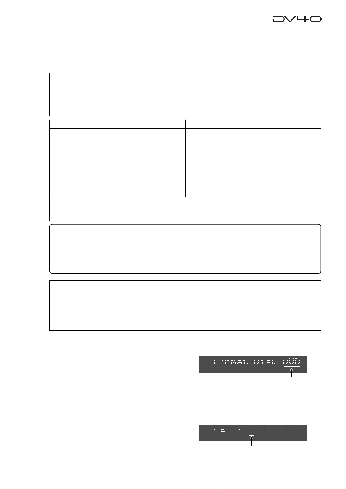
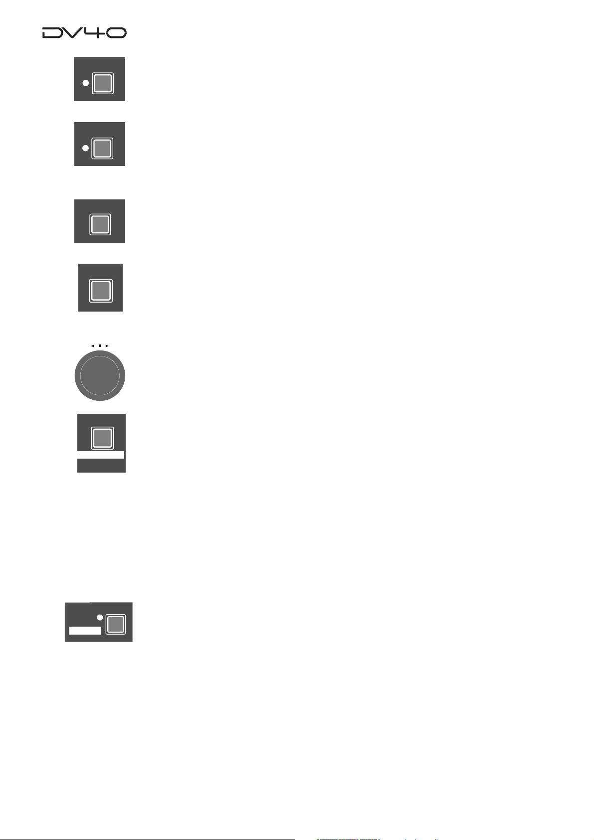
1. While "Format" with flashing "?" is shown on the display, press the [ENTER/YES] key.
The display changes to show "Format Disk DVD" (in which "DVD" is flashing).
Flashing
2.Press the [ENTER/YES] key again.
The display changes to show "Label [DV40-D VD" (in which "D" of "DV40" is flashing).
This shows the label name of the disk can be edited and "DV40-D VD" is the tentative name.
See the following Tips for details about how to enter a desired label name. Of course, you may use
the tentative name when formatting. (You can also rename the tentative name in the Utility mode
described later.)
Flashing
1-5
Page 18
Tips: How to enter a desired label name
Press the [MARGIN RESET/CLR] key repeatedly until the tentative name currently shown is erased.
By using the Jog dial (or using the appropriate numeric key), you can enter the desired character at the
editing point (flashing point). You can move the editing point by pressing [SKIP/CURSOR] I<</>>I key after
entering a character.
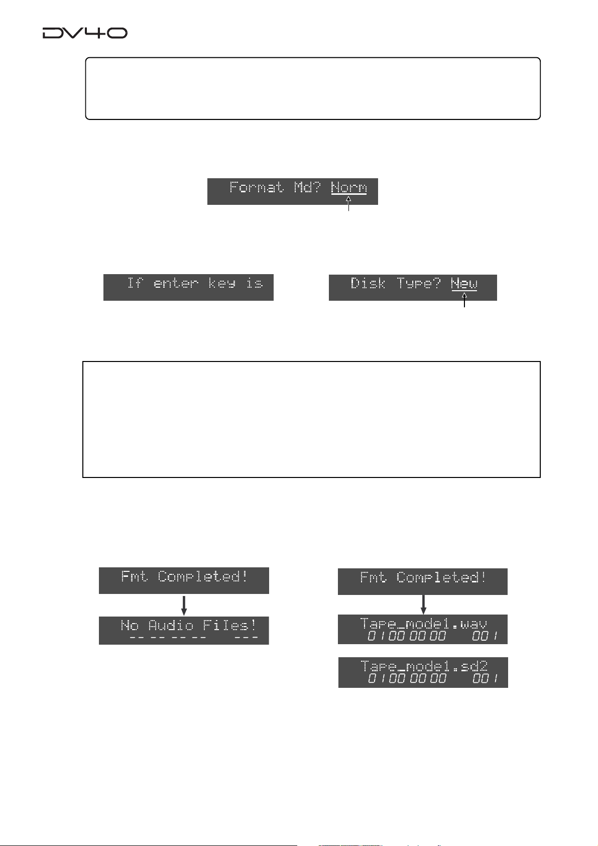
3.After entering a volume name, press the [ENTER/YES] ke y.
The display changes to show "Format Md?" with flashing "Norm".
You can select the format mode between "Norm" (Normal) and "Tape" using the jog dial.
Flashing
4.Select the format mode and press the [ENTER/YES] key.
If you select "Norm", the display shows "If enter key is pushed, will start formatting and delete D VD area data.
Are you sure?". If you are sure, proceed to the next step.
Flashing
If you select "Normal", go to the next step after the message above is shown.
When selecting "T ape", select "New" or "Used" using the jog dial, and then press the [ENTER/YES] key.
Go to the next step after the same message as above (shown when selecting “Norm”) is shown.
<Note>
• When formatting a used disk in the Tape mode, select
data may not be erased, with the result that a noise may generated when playing back the disk
or a recording error may occur when a new recording is made.
• If you format a disk in the Tape mode with "Disk Type" set to
formatting because the audio data area is also formatted. The display counts down the
unformatted area.
Because each of two
“T ape mode”
audio files reserves approximately 2GB of recording space,
the countdown of REMAIN starts from approximately 4GB.
"Used"
. If you select
"used"
, it takes some time for
"New"
, the existing
5.Press the [ENTER/YES] key.
If you set the disk type to "New", regardless of the format mode ("Norm" or "Tape"), the formatting
is completed quickly and "Fmt Completed!" is shown, followed by the screens as below depending on
the formatting mode.
Formatting a disk in the Normal mode
LTC
HMSF
After completing formatting a disk in the Normal mode, "No Audio Files!" appears, showing
that there is no audio file on the disk.
Note that the display shows the file format, track
mode and Fs/bit according to the settings of
[AUDIO FILE], [TR MODE] and [SAMPLING FREQ]
switches when the disk is formatted.
When performing recording in the NEW FILE
mode or creating file format, track format and
Fs/bit for a newly create audio file can be selected by the settings of these switches.
Formatting a disk in the Tape mode with "Disk Type" set to "New"
LTC
HMSF
or
LTC
HMSF
After completing formatting, two "Tape mode" audio files
are created, with appropriate audio file format (BWF or
SDII), track mode and Fs/bit according to the settings of
the [A UDIO FILE], [TR MODE] and [SAMPLING FREQ] switches.
Also, the “TAPE MODE” indicator (red) on the front panel
is lit.
1-6
Page 19
About audio files on a formatted disk
As described earlier, two format modes, Normal and T ape, are available with this unit, and in result, there
are two audio file types; "Normal mode" file and "Tape mode" file.
In short, a "Normal mode" file is a typical disk recorder file that can be edited comprehensively, while
a "Tape mode" file is more straightforward and you may regard it as a tape-like file.
The following describes detail information about disks formatted in Normal and Tape modes.
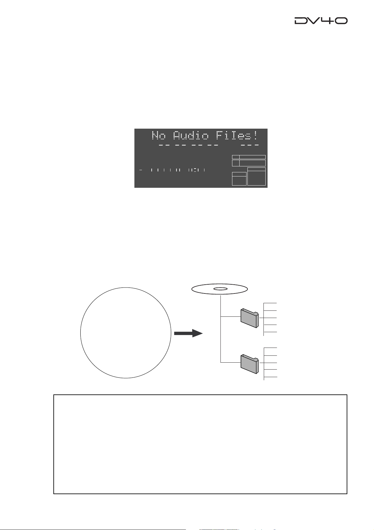
•A disk formatted in the "Normal" format mode
As described earlier in “Formatting a DVD-RAM disk”, the display shows “No Audio Files!” when formatted in the “Normal” format mode, showing that no audio file is created on the disk.
LTC
HMSF
1
2
50
60
∞
3
4
42 34 28 2018
8
12
To create a “Normal mode” audio file on a disk formatted in the “Normal” format mode, perform
recording in the NEW FILE mode or use the file select function.
Performing recording in the NEW FILE mode creates an audio file automatically, while the file select
function allows to create an audio file before preforming recording.
You can create audio files of two formats, BWF (Broadcast Wave Format) and SDII (Sound Designer II),
decided by the setting of the [AUDIO FILE] switch on the front panel.
A created file is stored in either of two directories, “bwff” for BWF (Broadcast Wave Format) and “sd2f”
for SDII (Sound Designer II) files.
You can create up to 200 audio files on a disk formatted in the “Normal” mode.
PGM
6543210OL
BIT
FS
kHz
FORMAT
BWF
24
48
CLOCK
-INT-
Disk just after formatted
*************.wav (001)
bwff
“No Audio Files!”
sd2f
*************.wav (002)
*************.wav (003)
*************.wav (004)
*************.wav (005)
*************.sd2 (001)
*************.sd2 (002)
*************.sd2 (003)
*************.sd2 (004)
*************.sd2 (005)
<Notes>
On a disk formatted in the “Normal” mode, the maximum recording space for each audio file is
approximately 2.0GB (the maximum recording time differs depending on the track mode, Fs and bit
length). If a file exceeds the maximum recording space during recording, the unit automatically
stops recording, while showing “File Size Over!” on the display.
Up to 200 audio files can be created on a disk, however, if the available space on the disk is short, the
number of audio files are limited.
For example, if there are two audio files each of which occupies 2.0GB disk space, the remaining
space is approximately 0.7GB.
If you create another audio file which occupies 0.7GB, you cannot create an audio file anymore. If
you try to make recording in the NEW FILE mode or to create an audio file using the file select
function, “Disk Full!” is shown on the display and the operation is rejected.
1-7
Page 20
•A disk formatted in the "Tape" format mode
Two “T ape mode” audio files (“BWF” or “SDII”) of approximately 2 GB size are created on a disk formatted
in the “T ape” format mode.
A created file are stored in either of two directories, “bwff” for BWF (Broadcast Wave Format) and “sd2f”
(Sound Designer II) files, according to the [AUDIO FILE], [TR MODE] and [SAMPLING FREQ] switch settings.
The two “Tape mode” audio files are more tape-like, so you may regard as if there were two analog tapes
on a disk. If an accident, such as a sudden power failure or shutdown of the unit, may happens during
recording, data on a “Tape mode” audio file recorded before the accident happens will survive (while,
in the same situation, all data on a “Normal mode” audio file will be lost).
“SDII” file
HMSF
12
8
6543210OL
PGM
BIT
FS
kHz
-0.1%
FORMAT
SDII
24
48
CLOCK
-INT-
LTC
1
2
60
∞
“BWF” file
HMSF
50
42 34 28 2018
12
8
6543210OL
LTC
PGM
BIT
FS
kHz
-0.1%
FORMAT
BWF
24
48
CLOCK
-INT-
1
2
50
60
∞
42 34 28 2018
<About the time display>
After completing formatting, the time of an audio file is shown in the LTC mode with one-hour offset to ABS 0
(LTC 01H: 00M: 00S: 00F). You can switch it to the ABS mode by pressing the [DISP TIME] key as many times as
required.
On a disk formatted in the “Tape” mode, two 2GB “Tape mode” files are automatically created, and no
more “Tape mode” audio file can be created.
Note that you can make recording to a “Tape mode” audio file only in the INSERT mode.
You can use the approximately 0.7GB remaining area on a disk formatted in the Tape mode as the
“Normal mode” area, to create “Normal mode” audio files (“BWF” or “SDII”). “Normal mode” audio files
are stored in the appropriate directories as shown in the figure below.
<Note>
When first time creating a “Normal mode” audio file in the “Normal mode” area (of approximately 0.7GB size) on
a disk formatted in the Tape mode, use the file select function (See 4-12 for details).
However, if any “Normal mode” audio file created is selected, you can create a new audio file by making recording in the NEW FILE mode.
A disk just after formatted
************.wav (001)
************.wav (002)
************.wav (003)
************.wav (004)
************.wav (005)
Tape_mode1.sd2 (001)
Tape_mode2.sd2 (002)
*************.sd2 (003)
*************.sd2 (004)
*************.sd2 (005)
bwff
or
sd2f
Tape Mode
File-1
Tape Mode
File-2
bwff
sd2f
Tape_mode1.wav (001)
Tape_mode2.wav (002)
*************.wav (003)
*************.wav (004)
*************.wav (005)
*************.sd2 (001)
*************.sd2 (002)
*************.sd2 (003)
*************.sd2 (004)
*************.sd2 (005)
bwff
sd2f
<Note>
With a “Tape mode” audio file, you cannot make editing such as inserting or cutting track data, and converting,
deleting or duplicating a file.
See "Chapter 4: Audio recording/playback" and "Chapter 9: Editing an audio file" for details about how to
create a new audio file.
1-8
Page 21
About REMAIN display
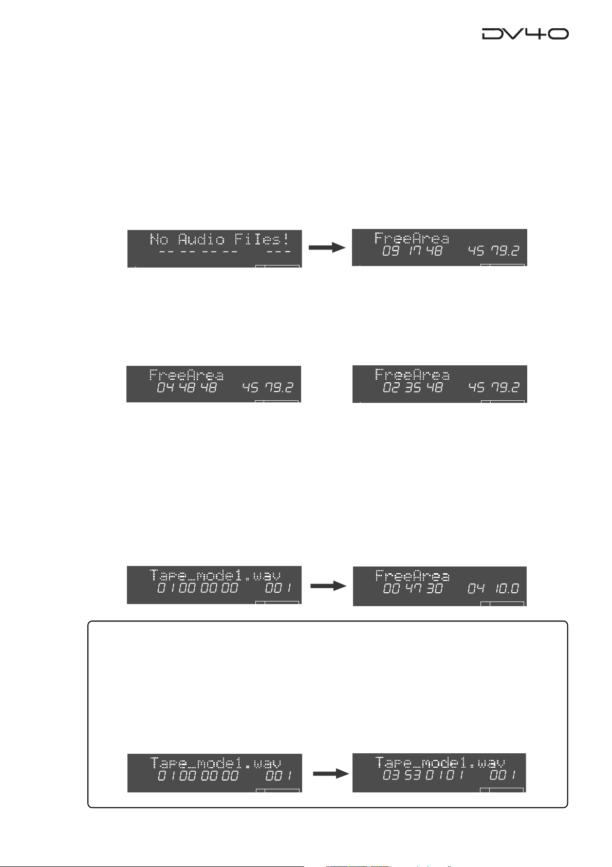
You can check the remaining (recordable) time/space by selecting the appropriate display using the
[DISP TIME] key. The unit can show the remaining time and space that can be used for "Normal mode"
files, regardless of whether the disk is formatted in the "Normal" or "Tape" mode.
• If a disk is formatted in the Normal mode
1. While a disk is stopped and the display shows "No Audio Files!", press the [DISP TIME] key three
times.
The display shows the "FreeArea" screen, in which the recordable space (in MB) and time (in hours/minutes/
seconds) for files with the current [TRACK MODE] and [SAMPLING FREQ] switch settings are shown.
The screen example on the right below shows the recordable time and space when the disk is formatted with the
[TR MODE] and [SAMPLING FREQ] switch settings to "MONO" and "44.1 kHz/24 bit" respectively.
LTC
HMSF
PGM
REMAIN
HMS
MB
2. Press the [TR MODE] and [SAMPLING FREQ] switches as desired.
By changing the [TRACK MODE] and [SAMPLING FREQ] switch settings, you can check the recordable space and
time according to the current switch settings.
The screen examples below shows the values in two cases when the [TR MODE] switch is set to "STEREO" and
"MULTI (4TR)" while the [SAMPLING FREQ] switch is fixed to "44.1 kHz/24 bit".
TR MODE -> "MULTI (4TR)"
REMAIN
HMS
MB
REMAIN
TR MODE -> "STEREO"
HMS
MB
• If a disk is formatted in the Tape mode
1. While the "Tape mode" audio file is selected, press the [DISP TIME] ke y three times.
The display shows the “FreeArea” screen, as with a disk formatted in the Normal mode. In this screen, the
recordable space (in MB) and time (in hours/minutes/seconds) for “Normal mode” files, with the same track mode
and sampling frequency/bit length settings as when the disk is formatted, are shown. In other words, the
recordable space shown here is the value calculated by subtracting 4.0 GB from all recordable space of the disk.
The screen example on the right below shows the values when the disk is formatted by setting the [TR MODE] and
[SAMPLING FREQ] switches to “MONO” and “48kHz/24bit” respectively.
The recording time in mono is 47 minutes 30 seconds, while the available space is 0.4 GB.
Note that, with a disk formatted in the Tape mode, if you change the settings of the [TR MODE] and [SAMPLING
FREQ] switches, the values on the display may not be changed.
LTC
HMSF
PGM
REMAIN
HMS
MB
BIT
24
<Tips>
The recordable space of each “Tape mode” file is fixed to approximately 2.0 GB, which is not included in the Free
Area, as shown above. You can see the maximum recordable time of the “Tape mode” audio file by following the
operation below.
• While a disk is stopped, press the [F FWD] key while holding down the [STOP] key.
The current position moves to the end of the “tape”, and the maximum recordable time of a “T ape mode” file, with
the track mode and sampling frequency/bit length selected by the [TR MODE] and [SAMPLING FREQ] switches
when formatted, is shown on the display.
You can calculate the remaining time of a “tape mode” file by subtracting the elapsed time from the maximum
recordable time.
LTC
HMSF
PGM
LTC
HMSF
PGM
BIT
1-9
Page 22

Page 23
Chapter-2
Names and Functions
This chapter describes names and functions of controls on the front panel, as well as
those of connectors on the rear panel.
Page 24
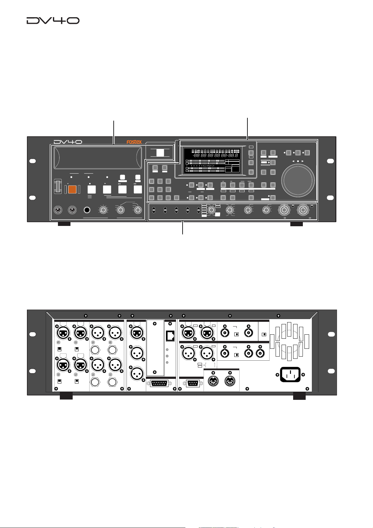
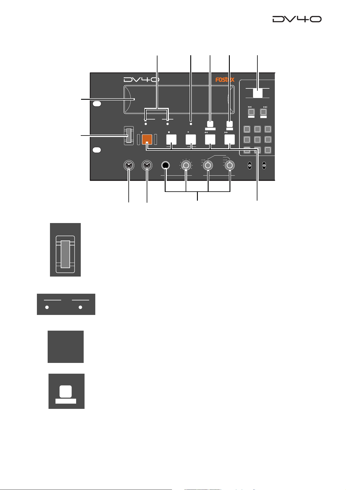
Front panel
We divide the front panel into three parts and describe names and functions of controls for each section.
*Some keys have the secondary function which is available when the SHIFT indicator is lit, while the primary
function is available when the SHIFT indicator is unlit. In this manual, we sometimes say "when shifted" and
"when unshifted" instead of "when the SHIFT indicator is lit" and "when the SHIFT indicator is unlit" respectively.
POWER
KEYBOARD
Front panel part 1
DVD MASTER RECORDER
HDDVD
STOPRECORD
SOURCE PLAY
LOCATE ABS 0
LOCATE REC END
TAPE MODE
PLAY
MAXMIN
TR1,3+2,4
PHONES
TR3+4
TR1+2
DRIVE
MOUSE
TC SETUP
REWIND
Front panel part 2
OPEN/CLOSE
SKIP/CURSOR
-
space
ABC3DEF
1
2
GHI JKL MNO
4
PQRS TUV WXYZ
89
REMOTE
LOCAL
CONTROL
AUDIO FILE
+
65
BWF
SDII
LIST PLAYCHASE
EDIT
F FWD
MONO
TR4
TR3
TR2
TR1
ANALOG
DIGITAL
SETUP
INLTC
DATE
YM
REMAIN
LOCATE
H
MSDFHSF
ABSCUE
CHASEOFFSETUBGENMEMORY
1
2
50
42 34 28 2018
60
∞
3
4
INPUT MON
TONE REC
MUTE REC
AUDIO RDY
NEW FILE
symbol
07
MONO
STEREO
MULTI(4TR)
INPUT
TR MODE
TC RDY
INSERT
176.4
96
+0.1%
88.2
NORM
48
-0.1%
44.1
48
PULL
UP/DOWN SAMPLING FREQ
12
8
6543210OL
24BIT
16BIT
CHASERDYTCDIGITAL
192
(kHz)
44.1
AUDIO EDIT UNDO
M
kHz 44.1 88.2 176.4
-0.1%
FORMAT
SDII
BWF
DVD
INSLATE TONEMUTE
SOURCE OUT
TR1
30
RSVD
FRAME RATE
DISP
TIME
S
%
dB
DISP
LEVELMARGINNEXTMBPGM
LEVEL
DSD96324824322016FSBIT
192
CLOCK
MARGIN
-INT-
-EXT-
RESET
WORD
VIDEO
DIGITAL
CLR
IN DSTOUT
PREVIEW
TR3
TR2
TR4
LOCATE
30DF
29.97
29.97DF
25
24
23.97
TC GEN MODE
24H RUN
REC RUN
FREE RUN
EXT RUN
SETUP
UTILITY
STORE
FILE SEL
DIRECTORY
SHIFT
ENTER/YESEXIT/NO
MEMORYCUE POINT
HOLD
INT
WORD
VIDEO
DIGITAL
MIN
TR1 INPUT LEVELTR2 TR4TR3CLOCK
BY-
PASS
ON
OFF
MINMAX MAX
SHUTTLEJOGVARI PITCH
ON
OFF
BY-
PASS
Front panel part 3
Rear panel
ANALOG INPUT BALANCED
TR3 TR1
+4dBu
-10dBV
TR4
+4dBu
-10dBV
1: GND 2: HOT 3: COLD
+4dBu
-10dBV
+4dBu
-10dBV
TR2
ANALOG OUTPUT
TR3 TR1BAL [+4dBu]
UNBAL
[-10dBV]
BAL [+4dBu]
TR4
UNBAL
[-10dBV]
1: GND 2: HOT 3: COLD
BAL [+4dBu]
BAL [+4dBu]
UNBAL
[-10dBV]
UNBAL
[-10dBV]
15P-REMOTE
ETHERNET
10/100
LINK
TX/RX
DIGITAL INPUT
TR4-3 TR2-1
TR2
DIGITAL OUTPUT
TR4-3 TR2-1
TR2
1:GND
2:HOT
3:COLD
9P-REMOTE
TR1
TR1
192kHz
TR1
176.4kHz
TR2
INPUT
VIDEO
INPUT
75Ω
OFF
ON
WORD
INPUT
75Ω
OFF
ON
GPI
OUTPUT
FAN
THRU
LO
THRU OUTPUT
HI
AC IN
TIME CODE
INPUT
THRU
TR2
OUTPUT
1: GND
2: HOT
3: COLD
2-2
Page 25
Front panel part 1
1
2
POWER
KEYBOARD
3
DVD MASTER RECORDER
DRIVE
HDDVD
STOPRECORD
MOUSE
1011
456 7
REWIND
LIST PLAYCHASE
EDIT
F FWD
MONO
TR4
TR3
TR2
TR1
SOURCE PLAY
LOCATE ABS 0
LOCATE REC END
TAPE MODE
PLAY
TR1,3+2,4
MAXMIN
TR3+4
TR1+2
PHONES
TC SETUP
9
OPEN/CLOSE
SKIP/CURSOR
-
space
ABC3DEF
1
2
GHI JKL MNO
4
PQRS TUV WXYZ
89
LOCAL
BWF
AUDIO FILE
REMOTE
CONTROL
8
+
65
07
ANALOG
DIGITAL
SDII
INPUT
POWER
DRIVE
CHASE
1. [POWER] switch
Turns on or off the power of the unit.
2. Disk tray
Loads a DVD-RAM disk. Use the [OPEN/CLOSE] key to open or close the tray.
3. [DRIVE (D VD/HD)] indicator s
The indicator for the current (currently selected) drive is lit.
HDDVD
In the initial condition, the "DVD" drive is selected.
4. [TAPE MODE] indicator
It is lit when a "TAPE mode" audio file is loaded.
See "Chapter 1: Before using the DV40" for details about the format mode.
5. [CHASE] ([TC SETUP]) key
This key has primary (unSHIFTed) and secondary (SHIFTed) functions.
TC SETUP
When unSHIFTed:
Turns on or off the chase mode.
When on, "CHASE" flashes in red on the display, which lights steadily when the unit
chase-locked to the external device.
When SHIFTed:
Enters the TC (Time code) setup mode, in which you can make settings for recording/playback of time code.
See "Chapter 5: Time code recording" for details.
2-3
Page 26
LIST PLAY
6. [LIST PLAY] ([EDIT]) key
This key has primary (unSHIFTed) and secondary (SHIFTed) functions.
EDIT
OPEN/CLOSE
When unSHIFTed:
Pressing this key allows you to select a list for executing the list play.
You can select between “SongLink” and “LTC_Link” lists.
After selecting the desired list, pressing the [PLAY] key starts the list play.
See “Chapter 11: List Play function” for details.
When SHIFTed:
Pressing this key enables editing of the recorded play list (Not supported!).
7. [OPEN/CLOSE] key
Opens or closes the disk tray.
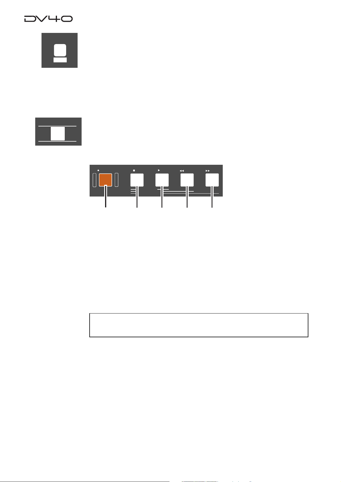
8. T ransport keys
PLAY
REWIND
cd
F FWD
e
a
STOPRECORD
SOURCE PLAY
LOCATE ABS 0
LOCATE REC END
b
a. [RECORD] key
Normally, pressing this key starts recording when one of the AUDIO RDY indicators
([NEW FILE] or [INSERT]) is lit.
• In the NEW FILE mode:
Starts recording to a new file which is automatically created. If the "TC RDY" indicator
is lit, time code is also recorded.
• In the INSERT mode:
Starts recording from the current position of the current file. If the "TC RDY" indicator is lit, time code is also recorded.
See "Chapter 4: Audio recording/playback" and "Chapter 5: Time code recording" for de-
tails.
<Note>
If you press the
"On", "Protected!"
[RECORD]
is shown and you cannot start recording.
key when the
"REC PROTECT"
setting in the Utility mode is set to
b. [ST OP] ke y
Normally, pressing this key stops the recorder.
In the Setup, Utility and all sort of editing mode, pressing this key exits the current
mode.
Also, pressing the [PLAY], [<< REWIND] or [>> F FWD] key while holding down this key
executes the following.
• [STOP] + [PLAY]
Plays back sound data on the clipboard and stops the recorder.
• [STOP] + [<< REWIND]
Locates to ABS 0 (the beginning position of the file) and stops the recorder.
• [STOP] + [>> F FWD]
Locates to REC END and stops the recorder.
2-4
Page 27
c. [PLAY] key
Normally, pressing this key starts playback.
Pressing this key during recording stores cross fade data to the memory and stops.
If any sound data is available on the clipboard, pressing this key while holding down
the [STOP] key plays back the sound data.
d. [|<<REWIND] key
Pressing this key while stopped rewinds the recorder at maximum 30 x speed.
Pressing this key during playback rewinds with sound (cues backwards) at 2 x speed.
Pressing this key while holding down the [STOP] key locates the "REC END" position
(the last recording position).
e. [>>| F FWD] key
Pressing this key while stopped fast-forwards the recorder at maximum 30 x speed.
Pressing this key during playback fast-forwards with sound (cues forwards) at 2 x
speed.
Pressing this key while holding down the [STOP] key locates the "ABS 0" position (the
beginning position of the file).
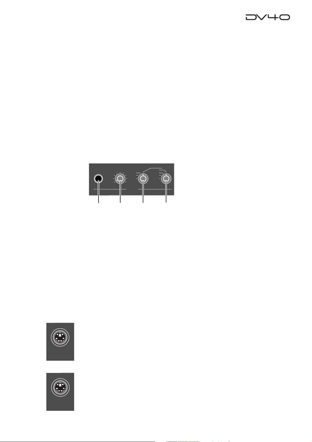
9. Monitor section
MONO
TR1,3+2,4
MAXMIN
PHONES
TR3+4
TR1+2
TR4
TR3
TR2
TR1
MOUSE
a
b
c
d
a. PHONES jack
Connects headphones for monitoring.
b. Headphones level contr ol
Adjust the level of headphones.
c. Monitor track selection s witch
Selects tracks to be monitored from among "1, 3+2, 4", "3+4" or "1+2"", or selects
MONO. When selecting MONO, you can select any mono track by using the Mono
track select switch.
d. Mono track select s witc h
Selects a track to be monitored from among tracks 1 through 4 when the Monitor
track selection switch is set to MONO.
10. [MOUSE] connector
Connecting a mouse to this connector (Not supported!).
KEYBOARD
11. [KEYBOARD] connector
Connecting a PS/2 keyboard to this connector.
See “Chapter 13: FTP server function” for details.
2-5
Page 28
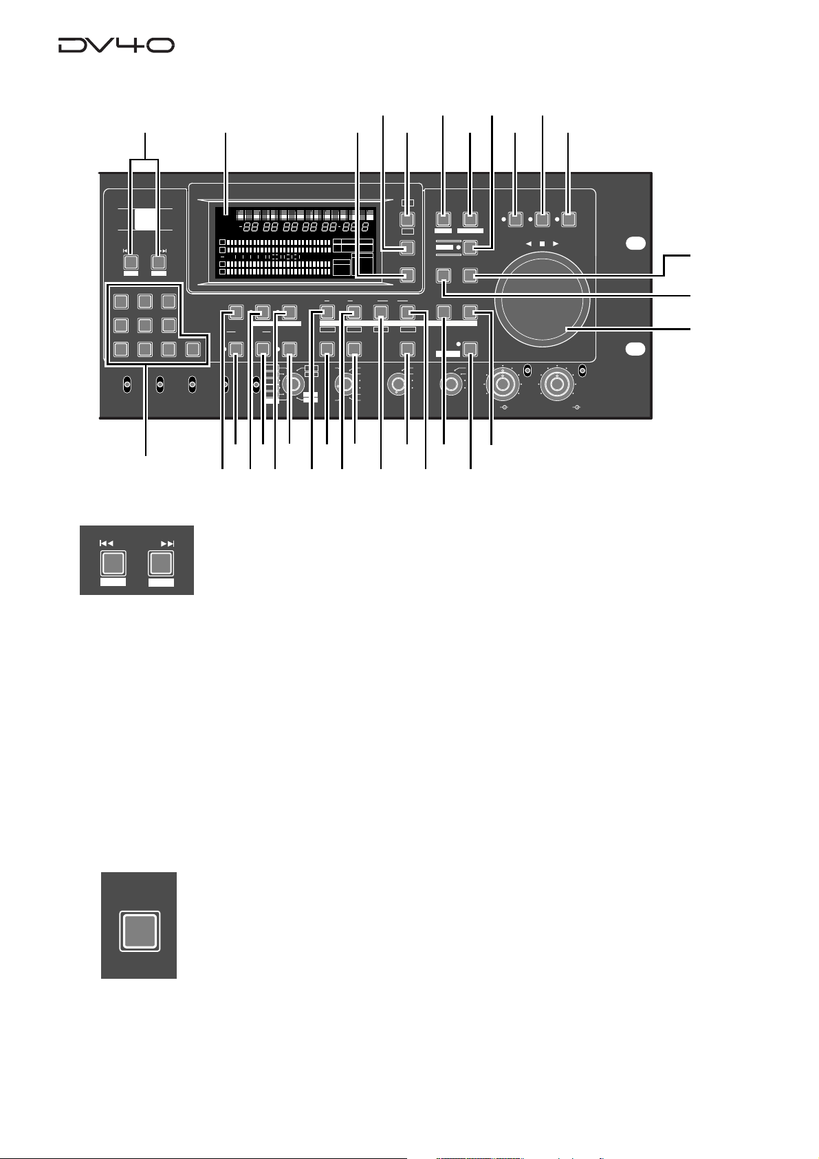
Front panel part 2
12
13
14
15
16
17
192021
18
22
OPEN/CLOSE
SKIP/CURSOR
-
space
ABC3DEF
1
2
GHI JKL MNO
4
PQRS TUV WXYZ
89
REMOTE
LOCAL
CONTROL
AUDIO FILE
42
SKIP/CURSOR
-
DISP
LEVELMARGINNEXTMBPGM
DSD96324824322016FSBIT
192
30DF
29.97
29.97DF
25
24
23.97
%
dB
IN DSTOUT
TR3
31
TIME
DISP
LEVEL
MARGIN
RESET
CLR
PREVIEW
TR4
LOCATE
TC GEN MODE
30
24H RUN
REC RUN
FREE RUN
EXT RUN
29
SETUP
INLTC
DATE
YM
REMAIN
LOCATE
H
50
42 34 28 2018
MUTE REC
+0.1%
NORM
-0.1%
PULL
38
39
MSDFHSF
CHASEOFFSETUBGENMEMORY
TONE REC
TC RDY
INSERT
176.4
96
88.2
48
44.1
48
36
37
8
12
ABSCUE
1
2
60
∞
3
07
symbol
MONO
STEREO
MULTI(4TR)
TR MODE
4
INPUT MON
NEW FILE
AUDIO RDY
UP/DOWN SAMPLING FREQ
+
65
ANALOG
BWF
DIGITAL
SDII
INPUT
40
41
M
CHASERDYTCDIGITAL
kHz 44.1 88.2 176.4
-0.1%
6543210OL
FORMAT
SDII
BWF
DVD
SOURCE OUT
INSLATE T ONEMUTE
TR2
TR1
AUDIO EDIT UNDO
30
192
24BIT
(kHz)
16BIT
44.1
RSVD
FRAME RATE
34
32
33
35
CLOCK
-EXTWORD
VIDEO
DIGITAL
S
-INT-
SETUP
UTILITY
SHIFT
STORE
HOLD
28
FILE SEL
DIRECTORY
ENTER/YESEXIT/NO
MEMORYCUE POINT
INT
WORD
VIDEO
DIGITAL
27
MIN
TR1 INPUT LEVELTR2 TR4TR3CLOCK
26
ON
OFF
BY-
PASS
SHUTTLEJOGVARI PITCH
MINMAX MAX
23
24
25
ON
OFF
BY-
PASS
12. [SKIP/CURSOR |<<, >>|] ([-], [+]) keys
This key has primary (unSHIFTed) and secondary (SHIFTed) functions.
+
When unSHIFT ed:
• Skips to the next (>>|) or previous (|<<) "ABS 0" of an audio file, cue point or MEM
point, depending on the setting of the "Skip Mode?" menu in the Setup mode.
In the initial setting, "File" is selected, so each press of the key skips to the next or
previous "ABS 0 (the beginning position)" of an audio file.
• In a character entering mode in which you have to move the cursor to a position to
be edited, pressing the key moves the cursor.
• While executing the list play, pressing the key moves to the next (>>|) or previous
(|<<) CUE point.
MARGIN
RESET
CLR
When SHIFTed:
• Enters the plus or minus sign while editing a time value.
13. FL displa y
Displays time information, track levels and other setting items, etc.
14. [MARGIN RESET/CLR] ke y
When the margin level is shown on the display, pressing this key resets the margin
level.
When editing a file name, volume name and cue name, pressing this key clears the
character in the current cursor position.
2-6
Page 29
DISP
TIME
15. [DISP TIME] key
Cycles through the time display modes as follows.
ABS
REMAIN
INT TC GEN
DISP
LEVEL
SETUP
UTILITY
L TC IN
LTC
16. [DISP LEVEL] key
When selecting any time display mode except "REMAIN" using the [DISP TIME] key,
this key cycles through the display mode as follows.
Time
T rack level
Margin level
The track level display varies depends on the track mode when recorded.
For example, if it is recorded with the mono track mode, only the level for track 1 is
shown.
17. [SETUP] ([UTILITY]) key
This key has primary (unSHIFTed) and secondary (SHIFTed) functions.
When unSHIFTed:
• Pressing this key while stopped enters the Setup mode, in which you can make
Setup menu settings.
When SHIFTed:
• Pressing this key while stopped enters the Utility mode, in which you can make
Utility menu settings.
To exit the mode, press the [EXIT/NO] key or [STOP] key.
See “Chapters 15 and 16” for details about the Setup and Utility modes.
FILE SEL
DIRECTORY
SHIFT
VARI PITCH
18. [FILE SEL] ([DIRECT ORY]) key
This key has primary (unSHIFTed) and secondary (SHIFTed) functions.
When unSHIFTed:
• Pressing this key while stopped enters the File select mode, in which you can select
an audio file or create a new file in the directory ("SDII" or "BWF") the current file
belongs to.
When SHIFTed:
• Pressing this key while stopped enters the Directory mode, in which you can select
an audio file from both "SDII" and "BWF" directories (Not supported!).
See "Chapter 9: Audio file mana gement" for details.
19. [SHIFT] key
Turns the shift mode on or on. When on, the indicator is lit.
You can execute a SHIFTed (secondary) function of a key which has dual functions.
The SHIFTed functions are labeled inversely on the panel, such as (PREVIEW) and
(HOLD).
20. [VARI PITCH] key
Turns the vari speed playback mode on or off. When on, the indicator is lit.
When the vari speed playback mode is active, you can change the speed directly
using the jog dial.
2-7
Page 30
JOG
21. [JOG] key
Pressing this key while stopped enters the jog mode, in which you can jog the recorder as if operating an analog recorder. When the jog mode is active, the indicator
is lit. To exit the jog mode, press any of the transport keys.
SHUTTLE
ENTER/YES
EXIT/NO
22. [SHUTTLE] ke y
Pressing this key during playback or while stopped enters the shuttle mode, in which,
using the jog dial, you can perform analog-tape-like shuttle at the speed between 0
and double speed or high-speed shuttle (audio is muted) at the speed between 0 and
32 times of the normal speed. When the shuttle mode is active, the indicator is lit.
23. [ENTER/YES] key
Used to confirm a setting or data entry or execute an operation.
24. [EXIT/NO] ke y
Used to cancel a setting or data entry or stop the current operation.
25. Jog dial
Used to jog or shuttle the recorder.
It is also used for increasing or decreasing the numeric value when editing a memory,
or used for selecting an item in the Setup mode.
STORE
HOLD
MEMORY
26. [MEMORY] ([PREVIEW]) key
This key has primary (unSHIFTed) and secondary (SHIFTed) functions.
When unSHIFT ed:
• In the normal display mode, pressing this key enters the memory edit mode, in
which you can edit memory point data.
Pressing this key after pressing the [STORE] key stores the holding time to a memory
point.
99 memory points (01 through 99) are available. You can give a name for each
point. (Note that memory points 01 through 03 are fixed and the rest (04 through
99) are user memory points.) See "Chapter 6: Storing time data" for details.
When SHIFTed:
• Pressing this key while stopped executes the fade-in preview at the desired memory
point. See "Chapter 8: Preview function" for details.
27. [STORE] ([HOLD]) key
This key has primary (unSHIFTed) and secondary (SHIFTed) functions.
When unSHIFT ed:
• Pressing this key during playback or while stopped holds the displayed time and
makes it possible to be edited. After editing the time, pressing this key again
followed by any of location memory keys (the MEMORY, CUE POINT, DEST-OUT,
DEST-IN, SOURCE-OUT and SOURCE-IN keys) stores the time to the appropriate
memory. See "Chapter 6: Storing time data" for details.
When SHIFTed:
• Pressing this key during playback or while stopped holds the displayed time and
makes it editable. After editing the time, pressing this key again and then any of
keys that can store time data (the MEMORY, CUE POINT, DEST-OUT, DEST-IN,
SOURCE-OUT and SOURCE-IN keys) stores the time to the appropriate memory.
See "Chapter 6: Storing time data" for details.
2-8
Page 31

CUE POINT
28. [CUE POINT] ([PREVIEW]) key
This key has primary (unSHIFTed) and secondary (SHIFTed) functions.
When unSHIFTed:
• In the normal display mode, pressing this key enters the cue point edit mode, in
which you can edit cue point data. Pressing this key after pressing the [STORE] key
stores the holding time to a cue point.
99 cue points (01 through 99) are available. You can give a name for each point.
See "Chapter 6: Storing time data" for details.
When SHIFTed:
• Pressing this key while stopped executes the fade-in preview at the desired cue
point. See "Chapter 8: Preview function" for details.
IN DST
PREVIEW
TR3
LOCATE
IN DST
PREVIEW
TR3
TR4
TR4
OUT
OUT
29. [DEST-OUT] ([PREVIEW]/[TR 4]) key
This key has primary (unSHIFTed) and secondary (SHIFTed) functions.
When unSHIFTed:
• Displays time data stored in this key so that you can edit the data.
• Pressing this key after pressing the [STORE] key stores the holding time or edited
time to the DEST-OUT point.
• When editing track data, this key selects track 4.
When SHIFTed:
• Pressing this key while stopped executes the fade-in preview at the DEST-OUT
point.
30. [LOCATE] key
Locates to the point where you pressed the [LOCA TE] key last time.
The data stored in this key is overwritten each time you press the key.
31. [DEST-IN] ([PREVIEW]/[TR 3]) key
This key has primary (unSHIFTed) and secondary (SHIFTed) functions.
When unSHIFTed:
• Displays time data stored in this key so that you can edit the data.
• Pressing this key after pressing the [STORE] key stores the holding time or edited
time to the DEST-IN point.
• When editing track data, this key selects track 3.
SOURCE
TR1
UNDO
OUTIN
TR2
When SHIFTed:
• Pressing this key while stopped executes the fade-out preview at the DEST-OUT
point.
32. [UNDO] key
By pressing this key, the history of the current audio file can be referred to, allowing
execution of the multiple undo function.
To execute the multiple undo function, select a desired history item using the jog
dial and press the [ENTER/YES] key.
See "Chapter 4: Audio recor ding/playback" for details.
33. [SOURCE-OUT] ([PREVIEW]/[TR 2]) key
This key has primary (unSHIFTed) and secondary (SHIFTed) functions.
When unSHIFTed:
• Displays time data stored in this key so that you can edit the data.
• Pressing this key after pressing the [STORE] key stores the holding time or edited
time to the SOURCE-OUT point.
• When editing track data, this key selects track 2.
When SHIFTed:
• Pressing this key while stopped executes the fade-in preview at the SOURCE-OUT
point.
2-9
Page 32

AUDIO EDIT
34. [AUDIO EDIT] key
pressing this key while stopped enters the menu selection mode for audio editing. In
this mode, you can select the editing menu by pressing this key repeatedly or by
using the jog dial. See "Chapter 9: Audio file management" and "Chapter 10: Editing track
data" for details.
SOURCE
TR1
TC RDY
SLA TE T ONE
TONE REC
OUTIN
TR2
35. [SOURCE-IN] ([PREVIEW]/[TR 1]) key
This key has primary (unSHIFTed) and secondary (SHIFTed) functions.
When unSHIFTed:
• Displays time data stored in this key so that you can edit the data.
• Pressing this key after pressing the [STORE] key stores the holding time or edited
time to the SOURCE-IN point.
• When editing track data, this key selects track 1.
When SHIFTed:
• Pressing this key while stopped executes the fade-out preview at the SOURCE-IN
point.
36. [TC RDY] key
Only when the NEW FILE or INSERT mode is active, pressing this key arms or unarms
the time code track.
See "Chapter 5: Time code recording" for details.
37. [SLATE TONE] ([TONE REC]) ke y
This key has primary (unSHIFTed) and secondary (SHIFTed) functions.
When unSHIFTed:
• While pressing down this key, the 1-kHz slate tone is output from all the output
connectors at the reference level.
• During recording, the 1-kHz slate tone is recorded while pressing down this key.
INSERT
MUTE
MUTE REC
When SHIFTed:
• During recording, pressing this key records the slate tone for the time set by the
"T one Rec?" menu in the Setup mode, and then continues normal recording.
• When the INSERT mode is active, pressing this key while stopped records the slate
tone for the time set by the "T one Rec?" menu in the Setup mode, and then stops.
38. [AUDIO RDY - INSERT] ke y
Pressing this key alternates on and off of the INSERT mode.
When the mode is active, you can turn on [TC RDY].
By recording to an existing file in the INSERT mode, you can replace the current
audio data with new one or add new audio data to the current one.
If you are going to make recording in the INSERT mode when there is no audio file,
the display shows "No Audio Files!".
See "Chapter 4: Audio recor ding/playback" for details about how to use this key.
39. [MUTE] ([MUTE REC]) key
This key has primary (unSHIFTed) and secondary (SHIFTed) functions.
When unSHIFTed:
• While holding down this key during playback, both the analog and digital outputs
except the PHONES output are muted.
• While holding down this key during recording, audio is muted and silence is
recorded.
When SHIFTed:
• During recording, pressing this key starts mute recording for the time set by the
"Mute Rec?" menu in the Setup mode, and then continues normal recording.
• When the INSERT mode is active, pressing this key while stopped starts mute
recording for the time set by the "Mute Rec?" menu in the Setup mode, and then
stops. See "Chapter 4: Audio recording/playback" for details about how to use this
key.
2-10
Page 33

NEW FILE
40. [AUDIO RDY - NEW FILE] key
Pressing this key alternates on and off of the NEW FILE mode.
When the mode is active, you can turn on [TC RDY].
In the NEW FILE mode, starting recording automatically creates a new file to be recorded. If the time code track is armed then, time code is also recorded simultaneously.
Note that you cannot record to a "Tape mode" audio file in the NEW FILE mode.
See "Chapter 4: Audio recor ding/playback" for details about how to use this key.
INPUT MON
space
ABC3DEF
1
2
GHI JKL MNO
4
PQRS TUV WXYZ
89
FL display
41. [INPUT MON] key
Turns on or off the input monitor mode. When on, the indicator is lit.
During recording, you always monitor the input signals regardless of the status of
the input monitor mode.
Also, when the "Auto EE MD?" menu in the Setup mode is set to "On", you always
monitor the input signals except for during playback, regardless of the status of the
input monitor mode.
42. Alphanumeric ke ys
These keys are used to directly enter alphanumeric characters when editing a name
65
or time, or specifying a memory or cue point.
For example, you can also use the "2" key to enter "a", "b", "c", "A", "B" and "C".
symbol
After entering the desired character, pressing one of the other alphanumeric keys
07
automatically moves the cursor to the next digit.
a
SETUP
INLTC
i
h
h
DATE
REMAIN
LOCATE
1
2
∞
3
4
ABSCUE
UB
GENMEMORY
50
60
YM
H
CHASEOFFSET
42 34 28 2018
D
MS
CHASERDYTCDIGITAL
8
12
6543210OL
HSFM
F
BIT
FS
kHz
-0.1%
FORMAT
44.1 88.2 176.4
CLOCK
BWF
SDII
DIGITAL
S
LEVELMARGINNEXTMBPGM
324824322016
96
-INT-
-EXTWORD
VIDEO
SD
192
%
b
dB
c
d
g
a. Displays a file name, menu title, etc.
b. Displays time data, system clock date, etc.
c. Displays the quantization bit number of the
current audio file. If it does not match the setting
of the [SAMPLING FREQ] switch on the front panel,
the bit number that matches the switch setting
flashes.
d. Displays the sampling frequency of the current
audio file. If it does not match the setting of the
[SAMPLING FREQ] switch on the front panel, the
sampling frequency that matches the switch
setting flashes.
e. Displays the current system clock. You can set the
system clock in the Setup mode.
2-11
f
e
f. Displays the current audio file format (“BWF” or
“SDII”). If it does not match the setting of the
[AUDIO FILE] switch on the front panel, the file
format that matches the switch setting flashes for
warning.
g. Displays the input/output levels of tracks 1
through 4. When performing the preview
function, it displays the status of the fade-in/out.
h. Displays the track mode of the current audio file.
If it does not match the setting of the [TR MODE]
switch on the front panel, the track mode that
matches the switch setting flashes for warning.
i. Displays the current display content or status
information.
Page 34

Front panel part 3
OPEN/CLOSE
SKIP/CURSOR
-
space
ABC3DEF
1
2
GHI JKL MNO
4
PQRS TUV WXYZ
89
REMOTE
LOCAL
CONTROL
AUDIO FILE
43
BWF
SDII
44
+
65
ANALOG
DIGITAL
INPUT
symbol
07
45
MONO
STEREO
MULTI(4TR)
TR MODE
SETUP
DATE
REMAIN
LOCATE
1
2
3
4
INPUT MON
46
INLTC
YM
H
ABSCUE
CHASEOFFSETUBGENMEMORY
50
42 34 28 2018
60
∞
MUTE REC
AUDIO RDY
NEW FILE
INSERT
176.4
96
+0.1%
88.2
NORM
48
-0.1%
44.1
48
PULL
UP/DOWN SAMPLING FREQ
47
MSDFHSF
CHASERDYTCDIGITAL
8
12
6543210OL
SOURCE OUT
INSLATE TONEMUTE
TONE REC
TC RDY
TR1
AUDIO EDIT UNDO
30
192
24BIT
(kHz)
16BIT
44.1
RSVD
48
M
kHz 44.1 88.2 176.4
-0.1%
FORMAT
SDII
BWF
DIGITAL
DVD
TR2
FRAME RATE
43. [CONTROL] s witc h
Selects whether controlling the unit remotely or from
the panel.
The unit is controlled remotely via the [9P-
REMOTE
LOCAL
When selecting REMOTE, you can prohibit the k e y operation
of the front panel controls. See "Chapter 15: Setup mode" for
details.
REMOTE] or [15P-REMO TE] connector on the
rear panel.
Also, you can send or receive file data using
FTP via the ethernet.
The unit is controlled from the front panel controls.
44. [AUDIO FILE] switch
Selects the audio file format (“BWF” or “SDII”) when
recording is made in the NEW FILE mode or when
creating or selecting an audio file by the file select
function.
• "OPTION" does not currently function.
45. [INPUT] switch
Selects the input between ANALOG and DIGITAL.
• When selecting "DIGITAL", "DIGITAL" flashes on
the display, which lights steadily when the unit
receives a correct external digital signal.
46. [TR MODE] switch
Selects the track mode for recording from among
MONO, STEREO and MULTI (4-track).
• If "MONO" is selected when the [INPUT] switch is
set to "DIGITAL", only the L-channel signal is re
corded to the mono track.
CLOCK
-EXTWORD
VIDEO
S
-INT-
LEVELMARGINNEXTMBPGM
DSD96324824322016FSBIT
192
30DF
29.97
29.97DF
25
24
23.97
%
dB
IN DSTOUT
TR3
TC GEN MODE
50
LEVEL
MARGIN
RESET
PREVIEW
LOCATE
TIME
DISP
DISP
CLR
TR4
24H RUN
REC RUN
FREE RUN
EXT RUN
SETUP
UTILITY
SHIFT
STORE
5149
HOLD
FILE SEL
DIRECTORY
ENTER/YESEXIT/NO
MEMORYCUE POINT
INT
WORD
VIDEO
DIGITAL
SHUTTLEJOGVARI PITCH
ON
OFF
BY-
PASS
MIN
TR1 INPUT LEVELTR2 TR4TR3CLOCK
MINMAX MAX
ON
OFF
BY-
PASS
52
47. [PULL UP/DOWN] switch
Selects pull-up (+0.1 %) or pull-down (-0.1 %) of the
sampling clock/TC frame rate.
+0.1%
NORM
-0.1%
Pulls up the selected sampling clock/TC
frame rate +0.1%.
Normal operation (0% = no pull-up or pulldown)
Pulls down the selected sampling clock/TC
frame rate -0.1%.
48. [SAMPLING FREQ] s witch
Selects the sampling frequency and quantization bit
for recording.
16BIT/44.1
16BIT/48
24BIT/44.1
24BIT/48
24BIT/88.2
24BIT/96
24BIT/176
24BIT/192
Up to 4 tracks of recording/playbac k
Up to 4 tracks of recording/playbac k
Up to 4 tracks of recording/playbac k
Up to 4 tracks of recording/playbac k
Up to 2 tracks of recording, up to 4 tracks of
playback
Up to 2 tracks of recording, up to 4 tracks of
playback
Up to 2 tracks of playbac k only
Up to 2 tracks of playbac k only
49. [FRAME RATE] switch
Selects the frame rate for recording, playback and
internal TC generator.
OPTION
23.976
24
25
29.97DF
29.97
30DF
30
American motion picture -0.1%
American motion picture
European film/PAL-SECAM video EBU
NTSC color with real time adjust
NTSC color
NTSC video/film
NTSC video/film
53
2-12
Page 35

50. [TC GEN MODE] switc h
Selects the generator mode for time code recording.
EXT RUN
FREE RUN
REC RUN
24H RUN
The external time code value is recorded as
the start time.
Runs the internal generator by the free run
mode, and records the current internal generator time as the start time.
When recording time code to a new file, the
generator records time code from the value
which continues to the last time code value
of the previous file.
Time code starts from the current time of the
internal clock of the unit.
51. [CLOCK] switch
Selects the system master clock.
INT
WORD
VIDEO
The internal clock is the master. "-INT-" is lit
on the display.
The external word clock is the master. "WORD-" flashes on the display, which lights
steadily when the unit locks to the word clock.
The external video clock is the master. "VIDEO-" flashes on the display, which lights
steadily when the unit locks to the video clock.
The external clock available in the digital sig-
DIGITAL
nal received via the [DIGITAL INPUT] connector is the master. "-DIGITAL-" flashes on
the display , which lights steadily when the unit
locks to the clock.
52. Analog Input Signal controls
Adjust the input levels for tracks 1, 2, 3, and 4 when
recording analog signals.
The outer knob controls track 1 and 3, while the
inner knob controls track 2 and 4.
53. [BYPASS ON/OFF] switch
Select whether bypassing the [INPUT LEVEL] controls
or not when recording analog signals.
When set to OFF, the corresponding [INPUT LEVEL]
controls are active.
When set to ON, the corresponding [INPUT LEVEL]
controls are inactive.
2-13
Page 36

Rear panel
3
1
234
5
6
7
ANALOG INPUT BALANCED
TR3 TR1
+4dBu
-10dBV
TR4
+4dBu
-10dBV
1: GND 2: HOT 3: COLD
+4dBu
-10dBV
+4dBu
-10dBV
TR2
ANALOG OUTPUT
TR3 TR1BAL [+4dBu]
UNBAL
[-10dBV]
BAL [+4dBu]
TR4
UNBAL
[-10dBV]
1: GND 2: HOT 3: COLD
BAL [+4dBu]
BAL [+4dBu]
UNBAL
[-10dBV]
UNBAL
[-10dBV]
TR2
1. Analog input/output section
BAL [+4dBu]
ANALOG OUTPUT
TR3 TR1BAL [+4dBu]
UNBAL
[-10dBV]
TR4
A
B
ANALOG INPUT BALANCED
TR3 TR1
+4dBu
-10dBV
TR4
+4dBu
-10dBV
TR2
TIME CODE
THRU
OUTPUT
1: GND
2: HOT
3: COLD
BAL [+4dBu]
BAL [+4dBu]
INPUT
UNBAL
[-10dBV]
15P-REMOTE
12
ETHERNET
10/100
LINK
TX/RX
DIGITAL INPUT
TR4-3 TR2-1
TR2
DIGITAL OUTPUT
TR4-3 TR2-1
TR2
1:GND
2:HOT
3:COLD
9P-REMOTE
11
TR1
TR1
192kHz
TR1
176.4kHz
TR2
INPUT
GPI
10
INPUT
INPUT
ON
ON
OUTPUT
VIDEO
75Ω
OFF
75Ω
OFF
FAN
THRU
LO
WORD
THRU OUTPUT
9
HI
AC IN
8
D. ANALOG OUTPUT (UNB AL) connector s (TR1 through
TR4)
• Each of these connectors outputs an unbalanced
analog audio signal of the corresponding track.
• Connectors: Phone type
• Nominal output level: -10 dBV
C
TR2
D
2. Time code input/output section
TIME CODE
INPUT
A
B
+4dBu
-10dBV
1: GND 2: HOT 3: COLD
2
3
+4dBu
-10dBV
1
UNBAL
[-10dBV]
1: GND 2: HOT 3: COLD
1
3
UNBAL
[-10dBV]
2
A. ANALOG INPUT (BALANCED) connectors (TR1 thr ough
TR4)
• Each of these connectors receives a balanced
analog audio signal, which is fed to the
corresponding track.
• Connectors: XLR-3-31 type (#2 = hot)
• Nominal input level: +4 dBu/-10 dBV selectable
B. Input level switc hes
• Each of these switches selects the nominal input
level between +4 dBu and -10 dBV for the
corresponding ANALOG INPUT connector.
C. ANALOG OUTPUT (BAL) connectors (TR1 thr ough TR4)
• Each of these connectors outputs a balanced
analog audio signal of the corresponding track.
• Connectors: XLR-3-32 type (#2 = hot)
• Nominal output level: +4 dBu
C
D
A
THRU
OUTPUT
2
B
1
1
3
2
C
3
1: GND
2: HOT
3: COLD
A. TIME CODE INPUT connector
• Receives external SMPTE/EBU time code.
• Connectors: XLR-3-31 type (#2 = hot)
B. TIME CODE THRU connector
• Echoes incoming SMPTE/EBU time code.
• Connectors: XLR-3-32 type (#2 = hot)
C. TIME CODE OUTPUT connector
• Outputs SMPTE/EBU time code from the unit.
• Connectors: XLR-3-32 type (#2 = hot)
3. Expansion slot
This expansion slot is used to fit the optional card.
Do not remove the blank panel unless you fit the
optional card.
2-14
Page 37

4. ETHERNET port
INPUT
75Ω
ON
OFF
THRU OUTPUT
WORD
A
B
C
D
ETHERNET
10/100
LINK
TX/RX
• Connects to an Ethernet network.
• Connector: IEEE802.3, conformed
to 10BASE-T/100BASE-T
• LED indicators
* 10/100: When the connection to
a network is established by
100BASE-TX, this indicator is lit.
(It is not lit when the connection
is established by 10BASE-T.)
* LINK: When the unit recognizes the
network, this indicator is lit.
* TX/RX: When data is transmitted
or/and received, this indicator is
lit.
7. Cooling fan motor speed select s witc h
Switches the cooling fan motor speed between LOW
and HI. Setting it to LOW lowers the motor noise.
8. AC IN connector
Connect the supplied power cord.
9. W or d c loc k section
5. Digital input/output section
A
DIGITAL INPUT
TR4-3 TR2-1
TR2
DIGITAL OUTPUT
TR4-3 TR2-1
TR2
1:GND
2:HOT
3:COLD
TR1
2
TR1
1
192kHz
TR1
176.4kHz
TR2
1
3
2
3
B
A. DIGITAL INPUT connectors
• Each connector accepts a digital signal conformed
to the IEC 60958 (AES/EBU) or IEC 60958 (S/P
DIF) format. The unit can automatically detect the
format.
• Connectors: XLR-3-31 type
B. DIGITAL OUTPUT connectors
• Each connector outputs a digital signal conformed
to the IEC 60958 (AES/EBU) or IEC 60958 (S/P
DIF) format. The format is selected in the Setup
mode.
• Connectors: XLR-3-32 type
A. WORD INPUT connector
• Accepts a word clock signal.
• Connector: BNC type
B. 75Ω (ON/OFF) switch
• To terminates the word clock, set this switch to
ON.
C. WORD THR U connector
• Echoes an incoming word clock signal.
• Connector: BNC type
D. WORD OUTPUT connector
• Outputs a word clock signal from the unit.
• Connector: BNC type
10. GPI input/output connector s
These connectors are active only when the "GPI ON/
OFF" menu in the Setup mode is set to "On". It is set
to "Off" in the initial setting, therefore, you have to
change it to "On" before using the GPI connectors.
GPI
INPUT
A
OUTPUT
5
4
1
2
3
B
6. Video clock section
VIDEO
INPUT
75Ω
ON
AB
A. VIDEO INPUT connector
• Accepts a video clock signal.
• Connector: BNC type
B. 75Ω (ON/OFF) switch
• To terminates the video clock, set this switch to
ON.
C. VIDEO THR U connector
• Echoes an incoming video signal.
• Connector: BNC type
THRU
OFF
C
2-15
A. GPI INPUT connector
• Connector: DIN-5 pin
• The following table shows the pin assignment.
A TTL-level, low active input signal activates the
operation.
Pin-1 GND
Pin-2 STOP
Pin-3 PLAY The low pulse signal activates the operation
Pin-4 >> The low pulse signal activates the operation
Pin-5 << The low pulse signal activates the operation
* The minimum input pulse width is 15 msec (except for Pin 2
PLA Y, whose minimum input pulse width is 5 msec).
The low plus signal activates the operation
equivalent to the STOP key operation.
equivalent to the PLAY key operation.
equivalent to the SKIP >> key operation.
equivalent to the SKIP << key operation.
Page 38

B. GPI OUTPUT connector
• Connector: DIN-5 pin
• The following table shows the pin assignment for
event outputs.
Pin-1 GND
Pin-2 EVENT 1
Pin-3 EVENT 0 Outputs an e vent at Cue point 0.
Pin-4 EVENT 2 Outputs an e vent at Cue point 2.
Pin-5 EVENT 3 Outputs an event at Cue point 3.
Each event signal is output by a 60 msec width, low level pulse
during recording/playback.
Outputs an event at Cue point 1.
11. 9-pin remote connector
12. 15-pin remote connector
These connectors are used for controlling the unit
from external devices.
The 9-pin and 15-pin remote connectors are tied in
parallel so you can use either of them depending on
the controller's hardware.
The 15-pin connector can supply the DC 12 V power,
so you can use it with a controller that requires the
power supply via the remote connector.
Pin No
1
2
3
4
5
6
7
8
9
10
11
12
13
14
15
Controller Out
DATA OUT
Frame Ground Frame Ground
Receive A
Transmit B
Transmit Common
Spare
Receive Common
Receive B
Transmit A
Frame Ground
D-sub 9P
DATA IN
Transmit A
Receive B
Receive Common
Spare
Transmit Common
Transmit B
Receive A
Frame Ground
D-sub 15P
DATA IN
Frame Ground
Transmit A
Receive B
Receive Common
Spare
Transmit Common
Transmit B
Receive A
Frame Ground
NC
NC
NC
NC
NC
+12V
A and B in the table above are defined as follows.
B
T
A
+
R
-
A<B -> “1” (Mark)
B<A -> “0” (Space)
The hardware of these connectors conforms to the
RS-422A, which can be selected in the Setup mode.
5
15
1
9
6
1
9
9P-REMOTE
15P-REMOTE
8
• Connector: 9-pin, D-sub connector (female)/9PREMOTE
15-pin, D-sub connector (female)/15P-REMOTE
• Protocol: Conformed to Sony 9-pin protocol.
Use a straight cable.
2-16
Page 39

Chapter 3
Reformatting/optimizing a disk
This chapter describes how to reformat a formatted disk and optimize a disk.
Page 40

Reformatting a D VD-RAM disk
The following describes how to reformat a used disk, while chapter 1 describes how to format
a new disk. We assume that a used DVD-RAM disk is inserted in the tray and stopped.
<Note for reformatting a disk in the Tape mode>
Before reformatting a used disk in the Tape mode, set the
MODE]
ated
switches on the front panel appropriately, which determine the behavior of the newly cre-
"Tape mode"
file.
<Note>
Memory point data still remain after reformatting a disk.
Therefore, if you do not need the old memory point data, delete them using the delete function.
See
"Chapter 6: Editing/storing time data"
for details about how to delete memory point data.
<Note>
• Before reformatting, make sure that the DVD-RAM disk is not write-protected.
• If you use an used DVD-RAM disk, we recommended to format the disk by a computer first, then
format it by the DV40.
1. While stopped, press the [SHIFT] key to turn on the indicator.
2. Press the [SETUP] key.
The unit enters the Utility mode and the display shows a setting menu.
The first time the unit enters the Utility mode after turning on the unit, the "Rec Protect?" menu is
shown. Otherwise, the previously used setting menu is shown.
[AUDIO FILE], [SAMPLING FREQ]
Flashing
and
[TR
BIT
1
2
60
∞
50
42 34 28 20 18
12
8
6543210OL
FS
kHz
-0.1%
FORMAT
BWF
24
48
CLOCK
-INT-
3. Use the jog dial to select the "Format?" menu and press the [ENTER/YES] key.
The display changes to show "Format Disk DVD".
1
2
60
∞
50
42 34 28 2018
Flashing
8
12
6543210OL
BIT
FS
kHz
-0.1%
FORMAT
BWF
24
48
CLOCK
-INT-
1
2
∞
50
60
42 34 28 20 18
12
8
6543210OL
Flashing
BIT
FS
kHz
-0.1%
FORMAT
BWF
24
48
CLOCK
-INT-
4. Press the [ENTER/YES] key again.
The display shows the following and now you can edit the label name of the disk (which is tentatively
named "DV40-DVD").
See the next "Tips" about how to edit a label name, although you may go to the next step without
editing the label name.
Flashing
1
2
60
∞
50
42 34 28 2018
3-2
12
8
6543210OL
BIT
FS
kHz
-0.1%
FORMAT
BWF
24
48
CLOCK
-INT-
Page 41

Tips: How to edit a label name
While the leftmost character of the tentative name is flashing, press the [MARGIN RESET/CLR] key
repeatedly to delete the name. Then, enter the desired alphanumeric characters using the nu-
meric keys or the jog dial.
When using the numeric keys, the editing point (flashing point) moves by pressing any of the
numeric keys after entering a character. When using the jog dial, you can move the editing point
by using the [SKIP/CURSOR] ([|<<] and [>>|]) keys.
5. Press the [ENTER/YES] key again.
The display changes to show "Format Md?" with flashing "Norm". You can select the format mode
between "Norm" (Normal) and "T ape" using the jog dial.
See "Formatting a DVD-RAM disk" in "Chapter 1 Before using the DV40" for details about the format mode.
Flashing
BIT
1
2
60
∞
50
42 34 28 20 18
12
8
6543210OL
FS
kHz
-0.1%
FORMAT
BWF
24
48
CLOCK
-INT-
6. Select the format mode and press the [ENTER/YES] key.
Depending on the format mode selected, the display shows as follows.
• When selecting "Norm":
The display scrolls "If enter key is pushed, will
start formatting and delete DVD area data. Are
you sure?".
• When selecting "Tape":
The display shows "Disk Type?" with flashing "New"
for selecting disk type. Select "Used" using the
jog dial, and then go to the next step.
Flashing
1
2
60
∞
50
42 34 28 2018
12
8
6543210OL
BIT
FS
kHz
-0.1%
FORMAT
BWF
24
48
CLOCK
-INT-
1
2
∞
50
60
42 34 28 20 18
8
12
6543210OL
BIT
FS
kHz
-0.1%
FORMAT
BWF
24
48
CLOCK
-INT-
If you select “Normal”, go to the next step after the message above is shown.
When selecting “Tape”, select “Ne w” or “Used” using the jog dial, and then press the [ENTER/YES] key.
Go to the next step after the same message as above (shown when selecting “Norm”) is shown.
<Note>
When a used disk previously formatted in the Tape mode is reformatted in the Tape mode by
"New"
selecting
for the disk type, the
are erased).
Therefore, if you record a new material to the old
exist together.
To erase all sound data when reformatting a disk in the Tape mode, make sure to select
the disk type.
"T ape mode"
file data is not erased (while
"Tape mode"
file, new and old materials may
"Normal mode"
"Used"
files
for
Tips: Special usage of "Ne w"
In general, "New" for the disk type is selected when formatting a new DVD-RAM disk.
However, there is a special case. If you cannot playback a recorded "Tape mode" file for any
reason, reformat the disk in the Tape mode by selecting "New" for the disk type.
Audio data on the "Tape mode" file still remains after reformatting and can be played back cor-
rectly.
<Note>
All the
"Normal mode"
files on the disk are erased.
3-3
Page 42

7. Press the [ENTER/YES] key.
• If you reformat the disk in the "Norm" mode, the formatting is completed quickly and "Fmt
Completed!" is shown, followed by "No Audio Files!" showing that there is no audio file on the disk.
LTC
HMSF
1
2
∞
50
60
42 34 28 2018
12
8
6543210OL
BIT
FS
kHz
-0.1%
FORMAT
BWF
24
48
CLOCK
-INT-
1
2
50
60
∞
42 34 28 2018
12
• If you reformat a disk in the "Tape" mode with "Disk T ype?" set to "Used", it takes some time for
formatting. The display counts down the unformatted area as the format is in progress.
When the format is completed, "Fmt Completed!" is shown, followed by the beginning of the "T ape
mode" audio file ("BWF" or "SDII").
REMAIN
MB
BIT
1
2
3
4
60
∞
50
42 34 28 2018
12
8
6543210OL
FS
kHz
-0.1%
FORMAT
BWF
24
48
CLOCK
-INT-
8
6543210OL
PGM
BIT
24
FS
48
kHz
CLOCK
-INT-
FORMAT
BWF
LTC
1
2
60
∞
HMS
50
42 34 28 2018
“SDII” audio file
12
8
6543210OL
BIT
1
2
50
42 34 28 2018
60
∞
F
PGM
BIT
24
FS
48
kHz
CLOCK
-0.1%
-INT-
FORMAT
SDII
12
8
6543210OL
LTC
1
2
∞
FS
kHz
-0.1%
FORMAT
BWF
50
60
24
48
CLOCK
-INT-
HMS
42 34 28 2018
12
8
6543210OL
F
PGM
BIT
24
FS
48
kHz
CLOCK
-0.1%
-INT-
FORMAT
BWF
“BWF” audio file
3-4
Page 43

Optimizing a disk
By optimizing a used disk, the deleted files are completely erased and you can reserve maximum free block space of the disk.
<Note>
After optimizing a disk, you cannot restore a deleted file.
<Note>
Before optimizing, make sure that the DVD-RAM disk is not write-protected.
If it is write-protected, you cannot optimize the disk.
1. While stopped, press the [SHIFT] key to turn on the indicator.
2. Press the [SETUP] key .
The unit enters the Utility mode and the display shows a setting menu.
3. Use the jog dial to select the "Optimize Disk?" menu and press the [ENTER/YES] key .
The display scrolls the warning message.
Flashing
REMAIN
MB
1
2
60
∞
50
42 34 28 2018
8
12
6543210OL
BIT
FS
kHz
FORMAT
BWF
24
48
CLOCK
-INT-
BIT
FS
kHz
-0.1%
FORMAT
BWF
24
48
CLOCK
-INT-
If you push ENTER key , will be unab le to restore
delete file!. Are you sure?
4. Press the [ENTER/YES] key .
The unit starts optimizing.
The display counts down the number as optimizing is in progress.
When optimizing is completed, "Completed!" is shown.
The number is counted down as optimizing is in progress.
REMAIN
1
2
60
∞
50
42 34 28 2018
12
8
6543210OL
BIT
FS
kHz
-0.1%
FORMAT
BWF
%
24
48
CLOCK
-INT-
REMAIN
MB
BIT
FS
kHz
-0.1%
FORMAT
BWF
24
48
CLOCK
-INT-
5. Press the [EXIT/NO] (or [STOP]) key.
The unit quits the Utility mode and the display shows the previous screen before entering the Utility
mode.
3-5
Page 44

Page 45

Chapter 4
A udio recording/pla yback
This chapter describes the basic audio recording/playback (for both analog and digital),
mute recording, slate tone recording, cueing by the jog/shuttle mode, etc.
Page 46

• About the expression for audio files in this man ual
As described in chapter 1, there are two types of audio file; "Normal mode" audio file and "Tape mode" audio
file. "T ape mode" audio file is rather special and can be created only when formatting. The following descriptions are mainly associated with a "Normal mode" audio file, therefore, a "Normal mode audio file" is sometimes referred to as "audio file" in this manual.
About the NEW FILE and INSERT mode
There are two recording modes; NEW FILE and INSERT modes.
• NEW FILE mode:
When performing recording in the NEW FILE mode, a new audio file is created automatically. The
recording is made from the beginning (ABS 0) of the new file, even if there is another audio file on the
disk.
• INSERT mode
By recording to an existing file in the INSERT mode, you can replace the current audio data with new
one or add new audio data to the current one. When recording to a “Tape mode” audio file, always use
the INSERT mode.
Recording/playbac k capabilities depending on the recor ding conditions (Fs/Bit/Track)
The table below shows the recording and playback capabilities depending on the recording conditions
(Fs, Bit length and the number of tracks) and the DVD-RAM disk capacity.
<Recording capabilities>
Recording conditions
44.1kHz/16Bit Mono
48kHz/16Bit Mono
44.1kHz/24Bit Mono
48kHz/24Bit Mono
88.2kHz/24Bit Mono
96kHz/24Bit Mono
176.4kHz/24Bit Mono
192kHz/24Bit Mono
44.1kHz/16Bit Stereo
48kHz/16Bit Stereo
44.1kHz/24Bit Stereo
48kHz/24Bit Stereo
88.2kHz/24Bit Stereo
96kHz/24Bit Stereo
176.4kHz/24Bit Stereo
192kHz/24Bit Stereo
44.1kHz/16Bit Multi (4)
48kHz/16Bit Multi (4)
44.1kHz/24Bit Multi (4)
48kHz/24Bit Multi (4)
88.2kHz/24Bit Multi (4)
96kHz/24Bit Multi (4)
176.4kHz/24Bit Multi (4)
192kHz/24Bit Multi (4)
4.7GB DVD
X
X
: V erify Write: OFF
<Playback capabilities>
Recording conditions
44.1kHz/16Bit Mono
48kHz/16Bit Mono
44.1kHz/24Bit Mono
48kHz/24Bit Mono
88.2kHz/24Bit Mono
96kHz/24Bit Mono
176.4kHz/24Bit Mono
192kHz/24Bit Mono
44.1kHz/16Bit Stereo
48kHz/16Bit Stereo
44.1kHz/24Bit Stereo
48kHz/24Bit Stereo
88.2kHz/24Bit Stereo
96kHz/24Bit Stereo
176.4kHz/24Bit Stereo
192kHz/24Bit Stereo
44.1kHz/16Bit Multi (4)
48kHz/16Bit Multi (4)
44.1kHz/24Bit Multi (4)
48kHz/24Bit Multi (4)
88.2kHz/24Bit Multi (4)
96kHz/24Bit Multi (4)
176.4kHz/24Bit Multi (4)
192kHz/24Bit Multi (4)
4.7GB DVD
X
X
4-2
Page 47

Recording an analog source in the NEW FILE mode
When performing recording in the NEW FILE mode, an audio file is newly created automatically and the recording is made from the beginning (ABS 0) of the new file. Note that you
cannot record to a "Tape mode" file or an existing "Normal mode" file in the NEW FILE mode.
In the following description, we assume that we are going to record an analog audio source in
stereo to a DVD-RAM disk just after formatted in the Normal mode.
<Note>
The first time you make recording to a disk just after formatted, the maximum recording size of
the audio file to be created is 2GB (the maximum recording time depends on the track mode and
Fs/bit settings). If the recording size exceeds 2GB during recording, the DV40 automatically stops
recording.
Preparation
Connection to external devices
1. Connect the e xternal source outputs to the [TR 1] and [TR 2] connectors of the [ANALOG INPUT
BALANCED] section of the unit.
The connectors used varies depending on the track mode setting.
2. Select the Input level switches appropriately accor ding to the sour ce output le vel.
3. Connect a pair of monitor speakers with built-in amplifiers or an amplifier/speaker system to the [TR
1] and [TR 2] connectors of the [ANALOG OUTPUT] section of the unit.
Use either of BAL or UNBAL connectors according to the inputs of the monitor device.
External Analog Audio Equipment
Analog Audio Signal
15P-REMOTE
ETHERNET
TX/RX
DIGITAL INPUT
TR4-3 TR2-1
TR1
TR2
DIGITAL OUTPUT
TR4-3 TR2-1
TR1
1:GND
2:HOT
3:COLD
9P-REMOTE
TR2
192kHz
TR1
176.4kHz
TR2
10/100
LINK
VIDEO
INPUT
75Ω
OFF
ON
WORD
INPUT
75Ω
OFF
ON
GPI
OUTPUT
INPUT
FAN
THRU
LO
THRU OUTPUT
HI
AC IN
ANALOG INPUT BALANCED
TR3 TR1
+4dBu
-10dBV
TR4
+4dBu
-10dBV
1: GND 2: HOT 3: COLD
+4dBu
-10dBV
+4dBu
-10dBV
TR2
ANALOG OUTPUT
TR3 TR1BAL [+4dBu]
UNBAL
[-10dBV]
BAL [+4dBu]
TR4
UNBAL
[-10dBV]
1: GND 2: HOT 3: COLD
BAL [+4dBu]
BAL [+4dBu]
UNBAL
[-10dBV]
UNBAL
[-10dBV]
TIME CODE
INPUT
THRU
TR2
OUTPUT
1: GND
2: HOT
3: COLD
4-3
Page 48

Preparation for recording
79
POWER
KEYBOARD
DRIVE
MOUSE
DVD MASTER RECORDER
TAPE MODE
HDDVD
PLAY
STOPRECORD
SOURCE PLAY
LOCATE ABS 0
LOCATE REC END
TR1,3+2,4
TR3+4
TR1+2
MAXMIN
PHONES
8
TC SETUP
REWIND
TR4
TR3
TR2
TR1
LIST PLAYCHASE
EDIT
F FWD
MONO
OPEN/CLOSE
SKIP/CURSOR
-
space
ABC3DEF
1
2
GHI JKL MNO
4
PQRS TUV WXYZ
89
REMOTE
LOCAL
CONTROL
AUDIO FILE
1
DISP
FILE SEL
SETUP
LTC
HMSF
1
2
50
42 34 28 2018
60
∞
+
INPUT MON
65
symbol
07
ANALOG
BWF
DIGITAL
SDII
INPUT
2
3
MUTE REC
AUDIO RDY
NEW FILE
INSERT
MONO
+0.1%
STEREO
NORM
MULTI(4TR)
-0.1%
PULL
UP/DOWN SAMPLING FREQ
TR MODE
45
PGM
BIT
kHz
-0.1%
8
12
6543210OL
FORMAT
BWF
SOURCE OUT
INSLATE TONEMUTE
TONE REC
TR1
TC RDY
AUDIO EDIT UNDO
176.4
88.2
44.1
30
192
96
24BIT
(kHz)
48
16BIT
44.1
RSVD
48
FRAME RATE
TIME
DIRECTORY
UTILITY
DISP
LEVEL
4824FS
CLOCK
-INT-
IN DSTOUT
TR3
TR2
30DF
29.97
29.97DF
25
24
23.97
MARGIN
RESET
PREVIEW
LOCATE
TC GEN MODE
SHIFT
ENTER/YESEXIT/NO
CLR
MEMORYCUE POINT
TR4
STORE
HOLD
24H RUN
REC RUN
FREE RUN
EXT RUN
6
INT
WORD
VIDEO
DIGITAL
ON
OFF
BY-
PASS
MINMAX MAX
MIN
TR1 INPUT LEVELTR2 TR4TR3CLOCK
9
1. Set the [CONTROL] s witc h to "LOCAL".
2. Set the [AUDIO FILE] switch to "BWF" or "SDII" appropriately.
When starting recording, an audio file with the selected file format is automatically created.
3. Set the [INPUT] switc h to "ANALOG".
4. Set the [TR MODE] switch to "STEREO".
5. Set the [SAMPLING FREQ] switch to the desired Fs/Bit position.
SHUTTLEJOGVARI PITCH
ON
OFF
BY-
PASS
6. Set the [CLOCK] switc h to "INT".
7. Press the [AUDIO RDY - NEW FILE] key to select the NEW FILE mode (the NEW FILE indicator is lit).
If you wish to record time code simultaneously, press the [TC RDY] key to turn on the indicator.
See "Chapter 5: Time code recording" for details about time code recording.
8. Connect a pair of headphones to the [PHONES] jack, and set the monitor track select switc h to "TR1
+ TR2" position.
9. Press the [INPUT MON] key to turn on the indicator, and use the [INPUT LEVEL] (TR 1 and TR 2)
controls to adjust the input levels of tracks 1 and 2.
See "Tips" below for details about the input level adjustment.
Even though you press the [INPUT MON] key to turn off the indicator after adjusting levels, the
monitor source automatically switches to the input source during recording.
From the "Auto EE MD?" menu in the Setup mode to "On" (which is defaulted to "Off"), you can set the
condition in which the input source can be monitored automatically. See "Chapter 15: Setup mode".
Tips: [BYPASS] switch
By setting the [BYPASS] switches beside the INPUT LEVEL controls to "ON", the INPUT LEVEL
controls are disabled.
4-4
Page 49

Recording
HMSF
2
1
-INT -
BWF
FORMAT
CLOCK
-0.1%
kHz
48
24
FS
BIT
PGM
LTC
∞
60
50
42 34 28 2018
12
8
6543210OL
1. Press the [RECORD] key.
"New File!" appears for a short time on the display and the unit starts recording on the newly created
file with the file format set in the procedure described in the previous "Preparation for recording".
A tentative title of the newly created audio file is automatically created and registered. The tentative
title contains date/time information. In the following example, the tentative title shows that the
recording started at 18H: 30M: 00S on 24th, December, 2001. The date/time is based on the internal
clock, which should be adjusted before using the unit. (See "Setting the internal clock" in Chapter 1
for details about how to set internal clock.)
You can edit the tentative title using the "Edit File Name?" menu in the Utility mode.
Tentative title
The leftmost “B” shows
that the file is “BWF”.
The appropriate tracks
according to the [TR
MODE] switch setting is
lit.
File number
The appropriate Bit and
Fs numbers according to
the [SAMPLING FREQ]
switch setting is lit.
The appropriate file format according to
the [AUDIO FILE] switch setting is lit.
Tips: File number f or a ne wly created file
Audio files automatically created are internally counted independently by "BWF" and "SDII" files.
For example, if you make recordings twice to a disk on which no audio file is available by setting the [AUDIO
FILE] switch to "BWF", two "BWF" files are created, whose file numbers are "001" and "002". Then if you make
a recording to this disk by setting the [AUDIO FILE] switch to "SDII", the file number of the newly created file
is "001". In result, two BWF files and one SDII file are created. A new file number is one greater than the
number of existing files of the same file format.
2. After recording, press the [ST OP] ke y to stop the unit.
See the next page for details about how to playback a recorded audio file.
Tips: Recor ding level adjustment of analog audio signals
Each level meter on the display holds peak value of the corresponding input signal (see the display example
below).
The peak hold time is initially set to 3 seconds, however, you can select the time among from 0 to 9 seconds
in 1 second steps and infinity using the "Peak Hold?" menu in the Setup mode. See "Chapter 15: Setup mode"
for details.
You can also check the margin between the allowable maximum input level (= 0 dB) and the actual loudest
level. The margin value (in dB) is updated each time when the loudest signal is fed to the unit.
So you can use the margin display function instead of setting the peak hold time to infinity. You can reset the
current margin value by pressing the [MARGIN RESET/CLR] key.
Using the [DISP LEVEL] key, you can choose what is shown on the display among the margin level, track level
and time.
ABS
1
2
∞
50
60
HMSF
8
42 34 28 2018
12
6543210OL
the peak value is hold.
PGM
BIT
FS
kHz
-0.1%
FORMAT
BWF
24
48
CLOCK
-INT-
4-5
Notes for level adjustment:
• Set the recording level with the [INPUT MON]
indicator lit.
• Adjust the recording level using the [INPUT
LEVEL] control so that the "OL" indicator does
not light at the loudest part of the signal (i.e.
the margin value is larger than 00.0 dB).
If the input signal is too high, it clips at the
full scale level.
Page 50

Playback of recor ded audio
PGM
NEXT
To check the recorded audio file after recording, follow the procedure below.
1. While holding down the [STOP] key, press the [REWIND] key.
The unit immediately locates to the beginning of the audio file.
2. Press the [PLA Y] ke y to start playback from the beginning of the audio file.
3. Monitor the playback audio via headphones or a monitor system.
If the analog outputs are connected to a mixing console, adjust the monitor level using the control of
the console. When the playback position reaches to the end of the audio file, the unit automatically
stops.
Tips:
After the audio file is recorded in the NEW FILE mode, you can overwrite the file or make recording following
the end of the file. See page 4-7 for details about the INSERT mode.
You can create an audio file before recording.
As explained earlier, when making recording in the NEW FILE mode, a new audio file is created on the
disk. Therefore, each time you make recording in the NEW FILE mode, the number of audio files increases by one. However, you can create a new audio file before making recording regardless of whether
"No Audio Files!" is shown or any audio file is already created. Note that you can only make recording to
the existing file in the INSERT mode described later. To create an audio files before making recording,
follow the procedure below.
1. Set the [AUDIO FILE], [TR MODE] and [SAMPLING FREQ] switches to the desired positions.
<Note>
A new file will be created with the appropriate audio file format, track mode and sampling frequency/bit
length combination according to the switch settings.
2. Press the [FILE SEL] ke y.
• When "No Audio Files!" is shown (i.e. there is no audio file on the disk), pressing the key brings up
"New File?" with flashing "001" on the display.
HMSF
ABS
PGM
Flashing
• If any audio file exists, the audio file number currently selected starts flashing.
By rotating the jog dial in this condition, you can bring up "New File?" with flashing "**" on the display
(where "***" is one greater than the number of the existing audio files).
In the display examples on the right, the number "001" file is selected. The new file number is "003",
because two audio files exist on the disk.
Flashing
LTC
HMSF
PGM
Flashing
3. Press the [ENTER/YES] key .
A new file is created and selected. The display shows the tentative title of the newly created file with
"L TC" time. You can make recording in the INSERT mode to an audio file created before recording.
You can also give a desired file title to the created file, or delete unnecessary files.
See "Chapter 9: Audio file mana gement" for details.
<Note>
If you create a new audio file when one or more audio files are available, the file number is counted independently by
files are available, the file number of the created
Therefore, when selecting a desired audio file from among more than one file, you must set the
switch appropriately. See "
"BWF"
and
"SDII"
files. For example, if you create an
"SDII"
Selecting a desired file on a disk"
"SDII"
file to a disk on which three
file is
"001"
.
on page 4-9 for details.
"BWF"
audio
[AUDIO FILE]
4-6
Page 51

Recording an analog sour ce in the INSERT mode
In the INSERT mode, recording is made to an existing audio file. You can overwrite the file from the
beginning or in the middle of the file, as well as make recording following the end of the file.
In the following description, as with the earlier description in “Recording an analog source in the NEW FILE
mode”, we assume that we are going to record an external stereo analog audio source from the [ANALOG
INPUT - TR1] and [ANALOG INPUT - 2] connectors to a DVD-RAM disk loaded in the tray.
We also assume to perform recording from the end point of the current audio file.
Tips:
In the INSERT mode, recording is made to an existing audio file. Therefore, set the [AUDIO FILE], [TR
MODE] and [SAMPLING FREQ] switches to the appropriate positions that match the audio file.
If you set any of these switches inappropriately, the switch position name flashes on the display for
warning.
• Preparation for recording
POWER
KEYBOARD
DRIVE
MOUSE
DVD MASTER RECORDER
TAPE MODE
HDDVD
PLAY
STOPRECORD
SOURCE PLAY
LOCATE ABS 0
LOCATE REC END
TR1,3+2,4
TR3+4
TR1+2
MAXMIN
PHONES
5
7
TC SETUP
REWIND
LIST PLAYCHASE
space
EDIT
1
F FWD
4
PQRS TUV WXYZ
MONO
TR4
TR3
TR2
REMOTE
TR1
LOCAL
CONTROL
OPEN/CLOSE
SKIP/CURSOR
-
+
ABC3DEF
2
GHI JKL MNO
89
BWF
SDII
AUDIO FILE
1
46
65
symbol
07
ANALOG
DIGITAL
INPUT
2
STEREO
MULTI(4TR)
TR MODE
MONO
LTC
HMSF
1
2
50
42 34 28 2018
60
∞
INPUT MON
MUTE REC
AUDIO RDY
NEW FILE
INSERT
176.4
+0.1%
NORM
-0.1%
PULL
UP/DOWN SAMPLING FREQ
TONE REC
TC RDY
96
88.2
48
44.1
48
12
8
6543210OL
24BIT
16BIT
AUDIO EDIT UNDO
192
(kHz)
44.1
PGM
BIT
4824FS
kHz
CLOCK
-0.1%
-INT-
FORMAT
BWF
SOURCE OUT
INSLATE TONEMUTE
IN DSTOUT
TR3
TR2
TR1
30DF
30
29.97
29.97DF
25
24
23.97
RSVD
FRAME RATE
MARGIN
PREVIEW
LOCATE
TC GEN MODE
LEVEL
RESET
DISP
FILE SEL
SETUP
TIME
DIRECTORY
UTILITY
DISP
SHIFT
ENTER/YESEXIT/NO
CLR
MEMORYCUE POINT
TR4
STORE
HOLD
24H RUN
INT
WORD
REC RUN
VIDEO
FREE RUN
EXT RUN
DIGITAL
MIN
TR1 INPUT LEVELTR2 TR4TR3CLOCK
3
6
BY-
PASS
ON
OFF
MINMAX MAX
SHUTTLEJOGVARI PITCH
ON
OFF
BY-
PASS
1. Set the [CONTROL] select switch to "LOCAL".
2. Set the [INPUT] select switch to "ANALOG".
3. Set the [CLOCK] select switch to “INT”.
4. Press the [AUDIO READY - INSERT] key to turn on the INSERT indicator .
If you want to record a time code simultaneously, press the [TC RDY] key to turn on the indicator.
See "Chapter 5: Time code recording" for details about time code recording.
5. Connect a pair of headphones to the [PHONES] jack, and set the monitor track selection s witc h to
"TR 1/TR 2".
6. Press the [INPUT MON] key to turn on the indicator, and use the [INPUT LEVEL] (TR 1 and TR 2)
controls to adjust the input levels of tracks 1 and 2.
See "Tips" on page 4-5 for details about the input level adjustment.
7. Press the [F FWD] key while holding down the [STOP] key.
The recorder skips to the recording end point.
• Recording
1. Press the [RECORD] key .
The recorder starts recording from the end point of the current file.
2. After recording, press the [ST OP] ke y to stop the unit.
Play back and check the recorded sound. If you are not satisfied with the result, use the multiple
undo function to go back to the previous condition and make recording again.
4-7
Page 52

Multiple-undo function
To undo recording, use the multiple-undo function.
Tips:
The history of takes starts by the date/time when the file was created, followed by the ending date/time of each
recording take, as illustrated below. By selecting the desired history event and performing the undo function,
you can recall the desired take.
date/time when
the file created
date/time of
take-1 end point
date/time of
take-2 end point
date/time of
take-3 end point
date/time of
take-4 end point
Time
<Notes for performing the multiple-undo function>
• You cannot undo recording on a
• The ending date/time of each take is memorized based on the internal clock, therefore, it is important to
adjust the date/time of the internal clock correctly.
• The unit keeps all takes on the disk in order to make the multiple-undo function for all takes of the current
audio file possible, therefore, the remaining disk space gets smaller each time you record another take.
To release the unnecessary take history (= undo file), use the
See
“Chapter 16: Utility mode”
"T ape mode"
for details.
audio file.
“Release Undo File?”
menu in the Utility mode.
1. Press the [UNDO] key.
The display changes to show "Select History?", as below.
The history keeps the date/time when the file was created and the ending date/time of each
recording take.
DATE
YMDHM
Flashing
S
BIT
1
2
50
60
∞
42 34 28 2018
12
8
6543210OL
FS
kHz
-0.1%
FORMAT
BWF
24
48
CLOCK
-INT-
2. Select the desired event from the history using the [JOG] dial (or the [SKIP/CURSOR] |<</>>| keys),
and press the [ENTER/YES] key.
After the first take has been completed, if you wish to return to the condition before recording, select
the date/time when the file was created.
"Multi Undo!" appears for a short time on the display, followed by "Undo Completed!", showing that the
undo operation is completed. The display changes to show the beginning of the audio file.
4-8
Page 53

Selecting a desired file on a disk
When there is more than one audio file (regardless of "BWF" or "SDII") on a disk, you can select a desired
file using the file select function, or using the [SKIP/CURSOR] [I<<]/[>>I] keys if the “skip mode” menu is set
to “File”.
The following describes how to select an audio file using the file select function. See "Chapter 9: A udio file
management" for details about how to select an audio file in the skip mode.
The following assumes that there are five "BWF" and three "SDII" files on the disk.
Tips:
When setting a disk that contains both "BWF" and "SDII" audio files, the "001" file of the type ("BWF" and/or
"SDII") set by the AUDIO FILE switch is selected.
• To select a file of the same file type
Follow the procedure below.
1. Press the [FILE SEL] key while stopped.
The current file number starts flashing.
2. Rotate the jog dial to select a desired file number, and press the [ENTER/YES] key.
You can select from among files of the same file type. For example, if "001" of the five "BWF" files is
currently selected, you can select among "001" through "005", as well as flashing "New File?" which
appears by rotating the jog dial fully clockwise. As explained earlier, "New File?" should be selected
when you create a new audio file.
After selecting the desired file number, pressing the [ENTER/YES] key switches the current audio file
to the selected one, and the display shows the beginning of the file.
• To select a file of the different file type
Follow the procedure below.
1. Set the [AUDIO FILE] switch to the desired position.
For example, if you want to select an "SDII" file when a "BWF" file is currently selected, set the [A UDIO
FILE] switch to "SDII".
In the "FORMA T " section on the display, "BWF" is lit while "SDII" flashes.
2. Press the [FILE SEL] key while stopped.
The current file number starts flashing.
3. Rotate the jog dial to select a desired file number, and press the [ENTER/YES] key.
You can select from among files of the selected file type in step 1 above. For example, if selecting from
among "SDII" files, you can select among "001" through "003", as well as flashing "New File?" which
appears by rotating the jog dial fully clockwise. As explained earlier, "New File?" should be selected
when you create a new audio file.
After selecting the desired file number, pressing the [ENTER/YES] key switches the current audio file
to the selected one, and the display shows the beginning of the file.
<Note>
When selecting an audio file, the track mode or Fs/bit shown on the display may flashes. This shows that the
position of the
switch appropriately to match the file.
[TR MODE]
or
[SAMPLING FREQ]
switch does not match the selected file. In such a case, set the
Tips:
See "Chapter 9: Audio file management " for details about how to create, select, delete an audio file or how to edit
a file name.
4-9
Page 54

Recording to a "Tape mode" audio file in the INSERT mode
You can record to a "T ape mode " audio file only in the INSERT mode.
If an accident may happens, such as a sudden power failure or shutdown of the unit, recorded data on
a "T ape mode" audio file will survive. Therefore, it will be suitable for live recording or preserving data
for a long period of time.
<Note>
• When formatting a disk in the Tape mode, two "Tape mode" audio files are created automatically.
Unlike a "Normal mode" audio file, you cannot create more than one "Tape mode" audio file on a disk.
however, note that you can create "Normal mode" audio files on a disk formatted in the Tape mode. (See the
next page.)
• You cannot undo a recording to a "
on the display and the key operation is ineffective.
• When "
Rec Protect"
menu in the Utility mode is set to "ON", you cannot make recording. See "Chapter 16:
Utility mode" for details about how to release the protection.
• You can record up to 2-GB audio data to a “Tape mode” audio file. The recorder automatically stops when it
elapses the maximum recording time. You can check the maximum recording time by pressing the
key while holding down the
You can record to a "Tape mode" audio file when either one of the displays below is shown.
The recording procedure is same as described in "Recording an analog source in the INSER T mode" on page
4-7.
[STOP]
Tape mode"
key.
file. If you press the
[UNDO]
key, "
History File Non
" is shown
[F FWD]
"SDII" audio file (file No.: 001)
LTC
HMS
1
2
50
60
∞
42 34 28 2018
8
12
"SDII" audio file (file No.: 002)
LTC
HMS
1
2
50
60
∞
42 34 28 2018
8
12
F
PGM
6543210OL
F
PGM
6543210OL
BIT
FS
kHz
-0.1%
FORMAT
SDII
BIT
FS
kHz
FORMAT
SDII
"BWF" audio file (file No.: 001)
LTC
HMS
24
48
CLOCK
-INT-
or
1
2
50
60
∞
42 34 28 2018
12
8
6543210OL
F
PGM
BIT
24
FS
48
kHz
CLOCK
-0.1%
-INT-
FORMAT
BWF
"BWF" audio file (file No.: 002)
LTC
HMS
24
48
CLOCK
-INT-
or
1
2
50
60
∞
42 34 28 2018
12
8
6543210OL
F
PGM
BIT
24
FS
48
kHz
CLOCK
-INT-
FORMAT
BWF
4-10
Page 55

Creating a "Normal mode" audio file on a disk formatted in the Tape mode
Two "Tape mode" audio files of approximately 2.0GB size are created on a disk formatted in the Tape
mode, spending 4GB disk space. Therefore, in the remaining 0.7GB space, you can create "Normal mode"
audio files.
1. While a "Tape mode" audio file is selected, press the [FILE SEL] key.
The current "Tape mode" file number flashes.
2. Rotate the [JOG] dial to show "New File?" with the flashing file number.
Depending on whether you change the [AUDIO FILE] switch setting or not before pressing the [FILE
SEL] key, the file number shown is different.
The following assumes that the current "Tape mode" file is "BWF".
• When the [A UDIO FILE] s witch is not changed (set to "BWF"):
"003" is shown, because a new "Normal mode" file is the third "BWF" file on the disk.
LTC
HMSF
PGM
Flashing
Flashing
• When the [A UDIO FILE] s witch is c hanged (set to "SDII"):
"001" is shown, because a new "Normal mode" file is the first "SDII" file on the disk.
LTC
HMSF
PGM
Flashing
3. Press the [ENTER/YES] key .
A new "Normal mode" file is created.
Tips:
If more than one “Normal mode” audio file is created on a disk formatted in the Tape mode and any “Normal
mode” audio file is currently selected, you can make recording in either the “NEW FILE” or “INSERT mode”.
• To select a desired audio file in the disk formatted in the T ape mode
Follow the same procedure as describe in "Selecting a desired file on a disk" on page 4-9.
<Note>
When loading a disk formatted in the Tape mode to the disk tray, the “
[AUDIO FILE]
For example, if you load a disk which contains both “
[AUDIO FILE]
switch setting (BWF or SDII) is selected.
switch set to “
SDII
”, the latter is selected.
Tape mode
” BWF and “
001
” audio file with the same type as
Normal mode
” SDII files, with the
4-11
Page 56

Recording a digital sour ce in the NEW FILE mode
The following describes how to record a digital source in the NEW FILE mode.
In the same way as recording an analog source, you can record a digital source in the NEW FILE mode to
a disk formatted in the Normal mode.
We assume that we are going to record a digital audio source in stereo.
<Note>
The first time you make recording to a disk just after formatted, the maximum recording size of
the audio file to be created is 2GB (the maximum recording time depends on the track mode and
Fs/bit settings). If the recording size exceeds 2GB during recording, the DV40 automatically stops
recording.
Preparation
Connection to external devices
1. Connect the external digital source outputs to the [TR2-1] of the [DIGIT AL INPUT] section of the unit.
Channels L and R of the source are assigned to tracks 1 and 2 of the unit respectively.
The digital input signal format (AES/EBU or S/P DIF) is automatically recognized.
<Note>
When receiving a stereo digital signal with 176.4 kHz or 192 kHz Fs, connect channels L and R of the source
to
[TR2-1]
and
[TR4-3]
of the
[DIGIT AL INPUT]
section respectively.
2. Connect a pair of monitor speakers with built-in amplifiers or an amplifier/speaker system to the [TR
1] and [TR 2] connectors of the [ANALOG OUTPUT] section of the unit.
3. If you want to lock the unit to a word or video signal, feed an appropriate external clock signal to the
[WORD IN] or [VIDEO IN].
ANALOG INPUT BALANCED
TR3 TR1
+4dBu
-10dBV
TR4
+4dBu
-10dBV
1: GND 2: HOT 3: COLD
+4dBu
-10dBV
+4dBu
-10dBV
TR2
ANALOG OUTPUT
TR3 TR1BAL [+4dBu]
UNBAL
[-10dBV]
BAL [+4dBu]
TR4
UNBAL
[-10dBV]
1: GND 2: HOT 3: COLD
External Digital Device
Digital Signal
(AES/EBU or S/P DIF)
BAL [+4dBu]
BAL [+4dBu]
UNBAL
[-10dBV]
UNBAL
[-10dBV]
TIME CODE
INPUT
THRU
TR2
OUTPUT
1: GND
2: HOT
3: COLD
ETHERNET
10/100
LINK
TX/RX
15P-REMOTE
DIGITAL INPUT
TR4-3 TR2-1
TR2
DIGITAL OUTPUT
TR4-3 TR2-1
TR2
1:GND
2:HOT
3:COLD
9P-REMOTE
TR1
TR1
192kHz
TR1
176.4kHz
TR2
VIDEO
INPUT
75Ω
OFF
ON
WORD
INPUT
75Ω
OFF
ON
GPI
OUTPUT
INPUT
FAN
THRU
LO
THRU OUTPUT
Word Cloc k
or
Video sync
HI
AC IN
4-12
Page 57

Preparation for recording
8
10
5
POWER
KEYBOARD
DRIVE
MOUSE
DVD MASTER RECORDER
TAPE MODE
HDDVD
PLAY
STOPRECORD
SOURCE PLAY
LOCATE ABS 0
LOCATE REC END
TR1,3+2,4
TR3+4
TR1+2
MAXMIN
PHONES
9
TC SETUP
REWIND
TR4
TR3
TR2
TR1
LIST PLAYCHASE
MONO
EDIT
F FWD
OPEN/CLOSE
SKIP/CURSOR
-
space
1
2
GHI JKL MNO
4
PQRS TUV WXYZ
89
REMOTE
LOCAL
CONTROL
AUDIO FILE
1
+
ABC3DEF
65
BWF
SDII
2
LTC
1
2
50
60
∞
INPUT MON
AUDIO RDY
NEW FILE
symbol
07
MONO
ANALOG
DIGITAL
INPUT
+0.1%
STEREO
NORM
MULTI(4TR)
UP/DOWN SAMPLING FREQ
TR MODE
46
3
HMSF
42 34 28 2018
TONE REC
MUTE REC
TC RDY
INSERT
176.4
96
88.2
48
-0.1%
44.1
48
PULL
12
8
6543210OL
192
24BIT
(kHz)
16BIT
44.1
AUDIO EDIT UNDO
PGM
BIT
964824FS
kHz
CLOCK
-0.1%
-INT-
FORMAT
BWF
SOURCE OUT
INSLATE TONEMUTE
IN DSTOUT
TR3
TR2
TR1
30DF
30
29.97
29.97DF
25
24
23.97
RSVD
FRAME RATE
LEVEL
MARGIN
RESET
PREVIEW
LOCATE
TC GEN MODE
DISP
FILE SEL
SETUP
TIME
DIRECTORY
UTILITY
DISP
SHIFT
ENTER/YESEXIT/NO
CLR
MEMORYCUE POINT
TR4
STORE
HOLD
24H RUN
INT
WORD
REC RUN
VIDEO
FREE RUN
DIGITAL
EXT RUN
MIN
TR1 INPUT LEVELTR2 TR4TR3CLOCK
BYPASS
ON
OFF
MINMAX MAX
SHUTTLEJOGVARI PITCH
ON
OFF
BY-
PASS
7
1. Set the [CONTROL] switch to "LOCAL".
2. Set the [AUDIO FILE] switch to "BWF" or "SDII" appr opriatel y.
When starting recording, an audio file with the selected file format is automatically created.
3. Set the [INPUT] switch to "DIGITAL".
"DIGIT AL" is shown on the display. It lights steadily or flashes depending on whether the appropriate
digital signal is fed or not.
4. Set the [TR MODE] switch to "STEREO".
5. Select the digital input tracks using the "D. IN Tr?" menu in the Setup mode, if necessary.
The "D. IN Tr?" menu is initially set to "Auto", in which the track numbers correspond to the input
numbers. See "Chapter 15: Setup mode" for details about the "D. IN Tr?" menu.
6. Set the [SAMPLING FREQ] switch to the desired Fs/Bit position.
7. Set the [CLOCK] switch to "DIGITAL".
"DIGIT AL" and "-EXT-" light up in the "CLOCK" section on the display, showing that the system clock is
derived from the digital input signal.
If you wish to make the unit slaved to a video or word clock, select the [CLOCK] switch to "VIDEO" or
"WORD" appropriately.
8. Press the [AUDIO RDY - NEW FILE] key to select the NEW FILE mode (the NEW FILE indicator is lit).
If you wish to record time code simultaneously, press the [TC RDY] key to turn on the indicator.
See "Chapter 5: Time code recording" for details about time code recording.
9. Connect a pair of headphones to the [PHONES] jack, and set the monitor track select switc h to "TR1
+ TR2" position.
10. Press the [INPUT MON] key to turn on the indicator.
You do not need to adjust the input level for digital recording.
You can check digital input levels from the level meters by activating the input monitor mode.
Recording
1. Press the [RECORD] key.
"New File!" appears for a short time on the display and the unit starts recording on the newly created
file.
2. After recording, press the [STOP] key to stop the unit.
If you are not satisfied with the result, undo the recording.
4-13
Page 58

Recording a digital sour ce in the INSERT mode
In the following description, we assume to perform recording from the end point of the current audio file, as in the description of the “Recording an analog source in the INSERT mode”
described earlier.
Tips:
In the INSERT mode, recording is made to an existing audio file. Therefore, set the [AUDIO FILE], [TR MODE] and
[SAMPLING FREQ] switches to the appropriate positions that match the audio file.
If you set any of these switches inappropriately, the switch position name flashes on the display for warning.
• Preparation for recording
8
7
3
POWER
KEYBOARD
DRIVE
MOUSE
DVD MASTER RECORDER
TAPE MODE
HDDVD
PLAY
STOPRECORD
SOURCE PLAY
LOCATE ABS 0
LOCATE REC END
TR1,3+2,4
TR3+4
TR1+2
MAXMIN
PHONES
6
TC SETUP
REWIND
LIST PLAYCHASE
TR4
TR3
TR2
TR1
EDIT
F FWD
MONO
OPEN/CLOSE
SKIP/CURSOR
-
space
1
2
GHI JKL MNO
4
PQRS TUV WXYZ
89
REMOTE
LOCAL
CONTROL
1
ABC3DEF
BWF
SDII
AUDIO FILE
DISP
FILE SEL
SETUP
LTC
HMSF
1
2
50
42 34 28 2018
60
∞
+
INPUT MON
STEREO
MULTI(4TR)
TR MODE
MONO
MUTE REC
AUDIO RDY
NEW FILE
INSERT
+0.1%
NORM
-0.1%
PULL
UP/DOWN SAMPLING FREQ
5
65
symbol
07
ANALOG
DIGITAL
INPUT
2
PGM
BIT
kHz
-0.1%
8
12
6543210OL
FORMAT
BWF
SOURCE OUT
INSLATE TONEMUTE
TONE REC
TR1
TC RDY
AUDIO EDIT UNDO
176.4
88.2
44.1
30
192
96
24BIT
(kHz)
48
16BIT
44.1
RSVD
48
FRAME RATE
TIME
DIRECTORY
UTILITY
DISP
LEVEL
4824FS
CLOCK
-INT-
IN DSTOUT
TR3
TR2
30DF
29.97
29.97DF
25
24
23.97
MARGIN
RESET
PREVIEW
LOCATE
TC GEN MODE
SHIFT
ENTER/YESEXIT/NO
CLR
MEMORYCUE POINT
TR4
STORE
HOLD
24H RUN
INT
WORD
REC RUN
VIDEO
FREE RUN
EXT RUN
DIGITAL
MIN
TR1 INPUT LEVELTR2 TR4TR3CLOCK
4
BY-
PASS
ON
OFF
MINMAX MAX
SHUTTLEJOGVARI PITCH
ON
OFF
BY-
PASS
1. Set the [CONTROL] select switch to "LOCAL".
2. Set the [INPUT] select switch to "DIGITAL".
3. Select the digital input tracks using the "D. IN Tr?" menu in the Setup mode, if necessary.
The "D. IN Tr?" menu is initially set to "Auto", in which the track numbers correspond to the input
numbers. See "Chapter 15: Setup mode" for details about the "D. IN Tr?" menu.
4. Set the [CLOCK] switch to "DIGIT AL".
"DIGIT AL" and "-EXT-" light up in the "CLOCK" section on the display, showing that the system clock is
derived from the digital input signal.
If you wish to make the unit slaved to a video or word clock, select the [CLOCK] switch to "VIDEO" or
"WORD" appropriately.
5. Press the [AUDIO READY - INSERT] key to turn on the INSERT indicator .
If you want to record time code simultaneously, press the [TC RDY] key to turn on the indicator.
See "Chapter 5: Time code recording" for details about time code recording.
6. Connect a pair of headphones to the [PHONES] jack, and set the monitor track selection s witc h to
"TR 1/TR 2".
7. Press the [INPUT MON] key to turn on the indicator.
You do not need to adjust the input level for digital recording.
You can check digital input levels from the level meters by activating the input monitor mode.
8. Press the [F FWD] key while holding down the [STOP] key to mo ve to the recor d end point.
Recording
1. Press the [RECORD] key.
The unit starts recording.
2. After recording, press the [STOP] key to stop the unit.
If you are not satisfied with the result, undo the recording.
4-14
Page 59

MUTE recording
mute space
Time
ABS 0
Recording end position
Time
ABS 0
mute space
You can make mute recording while maintaining the continuity of the ABS time (or LTC), or
insert a mute space at the beginning of an audio file or between songs.
• Creating a mute space during recording
You can create a mute space during audio recording (analog or digital) in both the NEW FILE and INSERT
mode.
The following description assumes that all preparation for recording is made.
1. Press the [RECORD] key to start recording.
2. Press and hold down the [MUTE] key from the desired position (the MUTE indicator is lit).
The unit mutes recording.
The headphones and analog outputs are also muted.
3. To stop m uting, release the [MUTE] key (the MUTE indicator turns off).
The unit continues recording a signal.
Press and hold down
the [MUTE] key.
Release the [MUTE] key.
mute space
Time
Tips:
Pressing the [MUTE] key during playback mutes all the (both analog and digital) audio outputs
except the monitor outputs (PHONES and MON OUT).
• Inserting a mute space at the beginning of an audio file or between songs
You can insert a mute space at the beginning of an audio file or between songs while stopped. This
operation is possible only in the INSERT mode.
The following assumes that the audio file is stopped at the beginning or at the end of the last recording.
1. Press the [AUDIO RDY - INSERT] key to turn on the INSERT indicator.
2. Press the [SHIFT] key to turn on the SHIFT indicator.
3. Press the [MUTE] key to turn on the MUTE indicator.
The unit performs mute recording for a duration set by the "Mute time setting" menu in the Setup
mode. The Mute time is initially set to 3 seconds.
After finishing mute recording, the unit stops.
See "Chapter 15: Setup mode" for details about the "Mute time setting" menu.
Inserting a mute space at the
beginning of an audio file or
between songs
Recording a mute space followed to the end point of the
last recording.
4-15
Page 60

Slate tone function
During playback or while stopped, you can feed the 1-kHz slate tone from all the outputs, as
well as record the slate tone for a specified duration at the beginning of an audio file or
between songs.
• Feeding the slate tone
1. Press and hold down the [SLA TE T ONE] ke y during pla ybac k or while stopped (the SLATE TONE
indicator is lit).
While holding down the [SLA TE TONE] key, the 1-kHz slate tone is fed from all the (digital and
analog) outputs of the unit.
2. To stop feeding the tone, release the [SLATE TONE] ke y (the SLATE TONE indicator turns off).
Tips:
During recording, pressing and holding down the [SLA TE TONE] key records the slate tone for the
duration.
• Recording the slate tone at the beginning of an audio file or between songs
You can insert the slate tone at the beginning of an audio file or between songs while stopped. This
operation is possible only in the INSERT mode.
The following assumes that the audio file is stopped at the beginning or at the end of the last recording.
1. Press the [AUDIO RDY - INSERT] key to turn on the INSERT indicator.
2. Press the [SHIFT] key to turn on the SHIFT indicator.
3. Press the [SLATE TONE] key to turn on the SLATE TONE indicator.
The unit performs slate tone recording for a duration set by the "Slate tone time setting" menu in the
Setup mode. The Slate tone time is initially set to 10 seconds.
After finishing slate tone recording, the unit stops.
See "Chapter 15: Setup mode" for details about the "Slate tone time setting" menu.
ABS 0
Inserting the slate tone at the
beginning of an audio file or
between songs
ABS 0
Recording the slate tone followed to the end point of the
last recording.
SLATE TONE
Time
Recording end point
SLA TE T ONE
Time
4-16
Page 61

Cueing by the jog function
You can cue audio sound using the jog function as if you operate an analog tape recorder.
1. While stopped, press the [JOG] key (the JOG indicator lights up).
The jog mode is active.
indicator above the jog dial lights up, showing that the recorder stills.
The
2. Rotate the jog dial to cue audio.
You can cue audio as if you are using an analog tape recorder.
While cueing, the appropriate < or > indicator above the jog dial is lit according to the rotating
direction.
3. To quit the jog mode, press any of the transport keys (the [STOP] key, etc.).
Cueing/high speed shuttle by the shuttle function
Using the shuttle function, you can perform the shuttle cueing or the high-speed search.
• Shuttle cueing
1. Press the [SHUTTLE] key during playback (the SHUTTLE indicator lights up).
The shuttle mode is active.
indicator light up, showing that the recorder stills.
The
2. Rotate the jog dial to start cueing.
You can cue forward or backward at a speed between 0 and twice the normal speed as if you are using
an analog tape recorder.
While cueing, the appropriate < or > indicator above the jog dial is lit according to the rotating
direction.
3. To quit the shuttle mode, press any of the transport keys (the [STOP] ke y, etc.).
If the cueing position comes to the ABS 0 or REC END point, the recorder automatically quits the
shuttle mode and stops.
• High-speed search
1. Press the [SHUTTLE] key while stopped (the SHUTTLE indicator lights up).
The shuttle mode is active.
indicator light up and the recorder stills.
The
2. Rotate the jog dial to start searching.
You can search forward or backward at a speed between 0 and 32 times of the normal speed.
While searching, the appropriate < or > indicator above the jog dial is lit according to the rotating
direction.
3. To quit the shuttle mode, press any of the transport keys (the [STOP] ke y, etc.).
If the cueing position comes to the ABS 0 or REC END point, the recorder automatically quits the
shuttle mode and stops.
4-17
Page 62

Page 63

Chapter 5
Time code recor ding
This chapter describes how to record time code generated by the internal time code
generator or external time code.
Page 64

Time code recording
The unit can be referenced to SMPTE/EBU time code. SMPTE time code is applied to countries
adopting the NTSC television system, while EBU time code is applied to countries adopting the
PAL/SECAM system.
Selecting the recording mode
Two methods are available for recording time code.
• Recording time code together with audio simultaneously
When recording audio and time code while creating a new file:
Use the [NEW FILE] mode.
When recording new time code to an existing file:
Use the [INSERT] mode to record both audio and time code simultaneously.
Selecting source time code
Two time code sources to be recorded are available.
• Time code generated by the internal time code generator.
• External time code received from the [TIME CODE INPUT] connector.
<Note>
Actually, the DV40 records only the starting time of time code in the dedicated area and does not
stripe it throughout a track. Therefore, recording time code does not consume the recording
space of a disk.
<Notes about recordable time code value>
Normally you can stripe any time code values in 24 hours to a file.
However, with a high-sampling “SDII” file, the recordable time code values are limited.
5-2
Page 65

Recording time code generated by the internal time code generator
You can record time code generated by the internal time code generator together with audio
simultaneously.
This section describes settings and operations for time code recording. See "Chapter 4: Audio re-
cording/playback" for details about settings and operations for audio recording.
The following description assumes that one of the [AUDIO RDY] key indicators ([NEW FILE] or
[INSERT]) is lit.
Settings of the DV40
• Front panel switc h settings
44
POWER
KEYBOARD
DRIVE
MOUSE
DVD MASTER RECORDER
TAPE MODE
HDDVD
PLAY
STOPRECORD
SOURCE PLAY
LOCATE ABS 0
LOCATE REC END
TR1,3+2,4
TR3+4
TR1+2
MAXMIN
PHONES
TC SETUP
REWIND
LIST PLAYCHASE
TR4
TR3
TR2
TR1
MONO
EDIT
F FWD
OPEN/CLOSE
SKIP/CURSOR
-
space
1
2
GHI JKL MNO
4
PQRS TUV WXYZ
89
REMOTE
LOCAL
CONTROL
AUDIO FILE
+
ABC3DEF
BWF
SDII
DISP
FILE SEL
SETUP
LTC
HMSF
1
2
50
42 34 28 2018
60
∞
INPUT MON
STEREO
MULTI(4TR)
TR MODE
MONO
MUTE REC
AUDIO RDY
NEW FILE
INSERT
+0.1%
NORM
-0.1%
PULL
UP/DOWN SAMPLING FREQ
65
symbol
07
ANALOG
DIGITAL
INPUT
PGM
BIT
kHz
-0.1%
8
12
6543210OL
FORMAT
BWF
INSLATE TONEMUTE
SOURCE OUT
TONE REC
TR1
TC RDY
AUDIO EDIT UNDO
176.4
88.2
44.1
30
192
96
24BIT
(kHz)
48
16BIT
44.1
RSVD
48
FRAME RATE
3
1
TIME
DIRECTORY
UTILITY
DISP
LEVEL
4824FS
CLOCK
-INT-
IN DSTOUT
TR3
TR2
30DF
29.97
29.97DF
25
24
23.97
MARGIN
RESET
PREVIEW
LOCATE
TC GEN MODE
SHIFT
ENTER/YESEXIT/NO
CLR
MEMORYCUE POINT
TR4
STORE
HOLD
24H RUN
INT
WORD
REC RUN
VIDEO
FREE RUN
DIGITAL
EXT RUN
MIN
TR1 INPUT LEVELTR2 TR4TR3CLOCK
2
1. Set the [FRAME RATE] s witch appropriately according to time code to be recorded.
2. Set the [TC GEN MODE] switch appropriately according to the situation.
24H RUN
REC RUN
FREE RUN
Time code starts from the current time of the internal clock of the unit.
When recording time code to a new file, the generator records time code from the value
which continues to the last time code value of the previous audio file.
Runs the internal generator by the free run mode, and records the current internal generator
time as the start time.
BY-
PASS
ON
OFF
MINMAX MAX
SHUTTLEJOGVARI PITCH
ON
OFF
BY-
PASS
EXT RUN
The external time code value is recorded as the start time.
<Note>
Unlike time code striped on an audio or video tape, time code on a disk is not striped from the
beginning to the end. Only the offset between the ABS time and time code at the recording
start point is recorded.
Therefore, if you record a discontinuous time code value in the middle, the unit cannot recognize it. Also, the user bit when time code starts recording is valid throughout the time code, so
the unit cannot handle the user bit that changes in the middle.
3. Press the [TC RDY] key to arm the time code trac k.
The TC RDY indicator is lit while "TC RDY" is shown on the display.
4. After pressing the [SHIFT] key to make the SHIFT mode active, press the [CHASE/(TC SETUP)] key to
enter the TC SETUP mode, then preset the internal time code generator time if necessary .
See page 5-6 for details about how to preset the internal time code generator time.
5-3
Page 66

Recording external time code
You can record time code together with audio while synchronizing the unit to external time
code generated by an external generator or striped on a video/audio tape, etc.
This section describes settings and operations for time code recording. See "Chapter 4: Audio
recording/playbac k" for details about settings and operations for audio recording.
The following description assumes that one of the [A UDIO RDY] key indicators ([NEW FILE] or
[INSERT]) is lit.
Connection to external devices/Settings of the DV40
• Connection to external devices
1. Connect the [ANALOG IN] (or [DIGITAL IN]) connector s to the audio outputs of a VCR.
2. Connect the [TIME CODE IN] connector to the time code output of a VCR.
3. If the video reference is available, connect it to the video inputs of both a VCR and the DV40.
Reference
VTR
External TC Generator
15P-REMOTE
ETHERNET
10/100
LINK
TX/RX
DIGITAL INPUT
TR4-3 TR2-1
TR2
DIGITAL OUTPUT
TR4-3 TR2-1
TR2
1:GND
2:HOT
3:COLD
9P-REMOTE
TR1
TR1
192kHz
TR1
176.4kHz
TR2
VIDEO
INPUT
75Ω
OFF
ON
WORD
INPUT
75Ω
OFF
ON
GPI
OUTPUT
INPUT
FAN
THRU
LO
THRU OUTPUT
HI
AC IN
ANALOG INPUT BALANCED
TR3 TR1
+4dBu
-10dBV
TR4
+4dBu
-10dBV
1: GND 2: HOT 3: COLD
-10dBV
-10dBV
UNBAL
[-10dBV]
UNBAL
[-10dBV]
TIME CODE
INPUT
THRU
TR2
OUTPUT
1: GND
2: HOT
3: COLD
ANALOG OUTPUT
TR3 TR1BAL [+4dBu]
BAL [+4dBu]
UNBAL
+4dBu
+4dBu
TR2
[-10dBV]
BAL [+4dBu]
TR4
UNBAL
[-10dBV]
1: GND 2: HOT 3: COLD
BAL [+4dBu]
• Front panel switc h settings
1. Set the [FRAME RATE] s witch appropriately to match the external time code.
2. Set the [TC GEN MODE] switch appropriately for recor ding the e xternal time code.
3. If the video reference is available, set the [CLOCK] s witc h to "VIDEO".
If you record time code by synchronizing the unit to digital clock from a VCR, set the switch to
"DIGITAL".
4. Press the [TC RDY] key to arm the time code track.
The TC RDY indicator is lit while "TC RDY" is shown on the display.
5. After pressing the [SHIFT] key to make the SHIFT mode active, press the [CHASE/(TC SETUP)] key to
enter the TC SETUP mode, then make the necessary settings for recording time code.
See 5-5 and subsequent pages for details about the TC Setup mode.
5-4
Page 67

TC Setup mode details
The TC Setup mode allows you to set the following which are necessary for recording/playback of time code or synchronizing the unit to external time code.
1. Editing time code generated by the internal TC generator
2. Editing the chase offset to external time code
3. Trimming the c hase offset
4. Chase mode selection
5. Capturing the L TC time f or storing it as the chase offset (Catc h offset)
6. Editing the LTC start time
7. Force jamming to external time code
8. Selecting output time code
9. Time code output on/off selection while paused
10. TC user bit output selection
• To enter the TC Setup mode
1. Press the [SHIFT] key to turn on the indicator, then press the [CHASE/(TC SETUP)] key.
The unit enters the TC Setup mode and the display shows a menu. The first time the unit enters the
TC Setup mode after turning on the power, the "Chase Offset?" menu is shown. Otherwise, the display
shows the menu previously selected.
HMSFSF
CHASEOFFSET
Flashing
2. Use the jog dial (or [SKIP/CURSOR] [|<<] / [>>|] keys) to select the desired menu.
You can cycle through menus in the following order (or reverse order).
HMSFSF
CHASEOFFSET
Flashing
HMSFSF
CHASEOFFSET
Flashing
HMSFSF
OFFSET
Flashing
Flashing
HMSF
GEN
Flashing
Flashing
Flashing
Flashing
HMSFSF
Flashing
5-5
HMSF
GEN
Flashing
Page 68

• Setting the internal TC generator start time
To set the internal TC generator start time, you must set the "TC GEN MODE" switch to "FREE
RUN".
1. Use the jog dial (or [SKIP/CURSOR] [|<<] / [>>|] keys) to select "Set Gen. TC?".
The display shows the internal TC generator time code running, together with "Set Gen. TC?".
2. Press the [ENTER/YES] key .
The current time is held and now it can be edited (with the flashing frame digit).
GEN
HMSF
Flashing Flashing
GEN
HMSF
3. Use the jog dial or numeric keys to enter a numeric value.
When using the jog dial to enter a value, you can move the (flashing) digit to be edited by using
the [SKIP/CURSOR] [|<<] / [>>|] keys.
When using the numeric keys to enter a time value, each number is entered from the right digit,
which moves left as additional digits are entered.
You can enter up to "23H 59M 59S **F" (in which ** is one smaller than the frame rate number).
4. After entering the time, press the [ENTER/YES] key.
The internal generator starts from the entered time when the [TC GEN MODE] switch is set to
“FREE RUN”.
The DV40 can start recording from the entered time when the [TC GEN MODE] switch is set to
“REC RUN”.
• Force-jamming to external time code
You can force-jam the internal generator time code to external time code.
To force-jam to external time code, you must set the "TC GEN MODE" switch to "FREE RUN".
The following procedure assumes that the unit receives external time code from the [TIME
CODE INPUT] connector.
1. Use the jog dial (or [SKIP/CURSOR] [|<<] / [>>|] keys) to select "Force JAM?" and press the
[ENTER/YES] key.
The unit force-jams to external time code and the force-jammed time code value is shown in
realtime.
GEN
HMSF
Flashing
<Notes>
• When carrying out the above operation, if the
panel does not match the frame rate of external time code,
operation is invalid.
• When carrying out the above operation, if no external time code is available,
appears.
HMSF
GEN
[FRAME RATE]
HMSF
GEN
switch setting on the front
"Illegal Frame!"
appears and the
"Void LTC In!"
5-6
Page 69

• Selecting output time code
When setting the [TC GEN MODE] switch to "FREE RUN" or "24H RUN", you can output time code
generated by the internal TC generator or recorded on the disk.
<Notes>
• The time code output selection is not effective when setting the
or
RUN"
"EXT RUN"
.
• While the unit outputs time code, the vari-pitch and word sync functions are not available.
• By turning off the power of the unit and then on, the selection of the
to
"REPRO"
which is the default.
1. Use the jog dial (or [SKIP/CURSOR] [|<<] / [>>|] keys) to select "TC OUT Sel?" and press the
[ENTER/YES] key.
The currently selected option (which is initially "Repro") starts flashing, showing it now can be
edited.
Flashing Flashing
2. Use the jog dial to select the desired option and press the [ENTER/YES] key .
You can select between "Repro" and "Gen.". Pressing the [ENTER/YES] key confirms the selection.
Repro The recorded time code on the disk is output from the [TOME CODE OUTPUT] connector.
Gen. The time code generated by the internal TC generator is output from the [TOME CODE
OUTPUT] connector.
[TC GEN MODE]
"TC OUT Sel?"
switch to
menu returns
"REC
3. To exit the TC Setup mode, press the [EXIT/NO] key (or the [STOP] key).
• Editing the chase offset
You can edit the current chase offset value. The edited value is stored to “CUE 00”.
1. Use the jog dial (or [SKIP/CURSOR] [|<<] / [>>|] keys) to select "Chase Offset?".
The current chase offset is shown.
2. Press the [ENTER/YES] key .
The subframe digit starts flashing, showing it now can be edited.
HMSFSF
CHASEOFFSET
Flashing
3. Use the jog dial or numeric keys to enter a offset value.
When using the jog dial to enter a value, you can move the (flashing) digit to be edited by using
the [SKIP/CURSOR] [|<<] / [>>|] keys.
When using the numeric keys to enter a time value, each number is entered from the right digit,
which moves left as additional digits are entered.
You can enter a value between "-12H 00M 00S **F 00SF" and "11H 59M 59S **F 99SF" (in which ** is
one smaller than the frame rate number).
HMSFSF
CHASEOFFSET
Flashing
4. After entering the offset value, press the [ENTER/YES] key.
The offset is set and the display returns to show "Chase Offset?".
If you enter an illegal value in step 3 and press the [ENTER/YES] key, "Illegal Time!" appears on the
display and the operation is canceled.
5. To exit the TC Setup mode, press the [EXIT/NO] key (or the [STOP] key).
5-7
Page 70

• Trimming the chase offset
You can trim the chase offset set by the procedure described above in "Editing the chase offset".
1. Use the jog dial (or [SKIP/CURSOR] [|<<] / [>>|] keys) to select "T rim?".
The current chase offset is shown.
2. Press the [ENTER/YES] key .
"+00s 00f 00sf" appears, in which "sf" flashes.
Flashing
HMSFSF
CHASEOFFSET
HMSFSF
CHASEOFFSET
Flashing
3. Use the jog dial or numeric keys to trim the value.
You can trim the value in sub-frame unit between "-59s **f 99sf" and "+59s **f 99sf" (in which ** is
one smaller than the frame rate number).
After trimming the value, do not forget the next step!
4. After trimming the value, press the [ENTER/YES] key.
The trimmed value is set and the display returns to show "T rim?".
5. To exit the TC Setup mode, press the [EXIT/NO] ke y (or the [STOP] key).
• Editing the LTC start time
You can set the LTC start time at the "ABS 0" (beginning of an audio file) position to a desired
value. The start time of time code recorded with the [TC READY] key set to ON can be edited
later. If you record time code with the [TC READY] key set to OFF, “01H 00M 00S 00F 00SF”
(default) is recorded as the start time.
Tips:
The unit records only the LTC start time. It generates and outputs time code in reference to the start time.
In a BWF file, the start time is stored in "Time Reference" in "Broadcast Audio Extension Chunk", while, in a SDII file,
it is stored in "Time Stamp" in "Region List Resource Spec".
Therefore, if you want to use this LTC by the Digidesign Pro Tools, make the User Time Code valid after importing the audio file.
1. Use the jog dial (or [SKIP/CURSOR] [|<<] / [>>|] keys) to select "Edit LTC Start?".
The current LTC time is shown.
2. Press the [ENTER/YES] key .
The subframe value of the LTC starts flashing, showing that it now can be edited.
HMSFSF
Flashing
HMSFSF
Flashing
3. Use the jog dial or numeric keys to enter a desired value.
When using the jog dial to enter a value, you can move the (flashing) digit to be edited by using
the [SKIP/CURSOR] [|<<] / [>>|] keys.
When using the numeric keys to enter a time value, each number is entered from the right digit,
which moves left as additional digits are entered.
You can enter up to "23H 59M 59S **F" (in which ** is one smaller than the frame rate number).
4. After editing the start time, press the [ENTER/YES] key.
The start time is set and the display returns to show "Edit L TC Start?".
5. To e xit the TC Setup mode, press the [EXIT/NO] ke y (or the [STOP] key).
To check the start time, press the [DISP TIME] key repeatedly until the display shows LTC.
5-8
Page 71

• Catch offset
you can capture the current LTC and store it as the chase offset by the "Catch Offset" function.
This function is available both during playback and while stopped.
1. Use the jog dial (or [SKIP/CURSOR] [|<<] / [>>|] keys) to select "Catch Offset?".
The current LTC is shown. (During playback, you can see LTC running.)
2. At the desired point, press the [ENTER/YES] key.
The currently displayed LTC value is set as the chase offset.
HMSFSF
OFFSET
Flashing
HMSFSF
CHASEOFFSET
Flashing
3. To exit the TC Setup mode, press the [EXIT/NO] key (or the [STOP] key).
• Chase mode selection
You can select the chase mode to the reference time code from among the following 3 modes.
Tips:
To make the unit chase to the reference time code, press the [CHASE] key to activate the chase mode.
When activating the chase mode, the [CHASE] key flashes, as well as "CHASE" flashes in red on the display.
When the unit locks to the reference time code, both the [CHASE] key and "CHASE" on the display are lit
steadily.
Once
Continue
In this mode, once the unit locks to the incoming time code after activating the chase mode (by
pressing the [CHASE] key), it stops chasing and runs freely, ignoring the incoming time code.
The unit does not rechase the time code even if it runs out of sync to the time code.
In this mode, once the unit locks to the incoming time code after activating the chase mode (by
pressing the [CHASE] key), it stops chasing and runs freely, ignoring the incoming time code.
The unit rechases the incoming time code if it runs out of sync to the time code.
In this mode, after the unit locks to the incoming time code, it continues to monitor the
Frame Sync
incoming time code and control the speed to keep locking to the incoming time code by using
the small amount of vari speed which is inaudible.
The unit rechases the incoming time code if it runs out of sync to the time code.
1. Use the jog dial (or [SKIP/CURSOR] [|<<] / [>>|] keys) to select "Chase MD?".
The current chase mode is shown.
2. Press the [ENTER/YES] key .
The current chase mode starts flashing.
FlashingFlashing
3. Use the jog dial to select a desired chase mode and press the [ENTER/YES] key .
The selected chase made is set and the display returns to show "ChaseMD?".
4. To exit the TC Setup mode, press the [EXIT/NO] key (or the [STOP] key).
5-9
Page 72

• Time code output on/off selection while paused
you can select whether to output time code from the [TIME CODE OUTPUT] connector while
paused.
1. Use the jog dial (or [SKIP/CURSOR] [|<<] / [>>|] keys) to select "Pause TC?".
The current setting is shown (the default is “Off”).
2. Press the [ENTER/YES] key .
The currently value flashes and you can now edit it.
Flashing
Flashing
3. Use the jog dial (or [SKIP/CURSOR] [I<<] / [>>I] keys) to select “On” or “Off” and press the [ENTER/
YES] key.
Time code is not output from the [TIME CODE OUTPUT] connector while paused.Off (default setting)
Time code is output from the [TIME CODE OUTPUT] connector while paused.On
4. To exit the TC Setup mode, press the [EXIT/NO] key (or the [STOP] key).
• TC user bit output selection
This menu allows to select the TIME CODE UBIT information attached to the time code output
from the DV40.
The date information on “MDYf” and “DMYf” is taken out from the internal clock on DV40 and
is based on the time when the file is created. “SRNo” information is derived from the 3-digit
REEL NUMBER attached to the VOLUME LABEL set in the “Edit V olume Lbl?” Utility menu or
SCENE/REEL NUMBER set in the “Set SCENE & REEL?” menu.
1. Use the jog dial (or [SKIP/CURSOR] [|<<] / [>>|] keys) to select "TC UBIT Sel?".
The current setting is shown (the default is “SRNo”).
2. Press the [ENTER/YES] key .
The currently value flashes and you can now edit it.
Flashing
Flashing
3. Use the jog dial (or [SKIP/CURSOR] [I<<] / [>>I] keys) to select the desired option and press the
[ENTER/YES] key.
You can select from among the following options.
SRNo (default setting)
MDYf (for U.S.A.)
DMYf (for European countries)
SSSSS : SCENE No. *SSSSS = sssss (Volume Label sssss) + File No.
RRR : REEL No. (Tape No.)
xx : File No. (Hexadecimal, 01 ~ c7)
BG_76543: SSSSS/BG_210: RRR
BG_76: MM (month)/BG_54: DD (day)/BG_32: YY (year)/BG_10: xx
BG_76: DD (day)/BG_54: MM (month)/BG_32: YY (year)/BG_10: xx
5-10
Page 73

• Selecting “SRNo” as TC UBIT inf ormation
If “SRNo” is selected, the following 8-digit TC UBIT information derived from the 3-digit REEL
NUMBER attached to the VOLUME LABEL set in the “Edit Volume Lbl?” Utility menu or the SCENE/
REEL NUMBER set in the “Set SCENE & REEL?” Utility menu will be output.
SSSSSRRR SSSSS: SCENE No. derived from “Set SCENE & REEL?” Utility menu + File No.
RRR: 3-digit REEL No. derived from “Edit Volume Lbl?” Utility menu or “Set
SCENE & REEL?” Utility menu.
<Example-1> <Example-2>
VOLUME LABEL: DV40SCENE/REEL No.: 00000 / 002 SCENE/REEL No.: 00006 / 005
File No.: 001 File No.: 002
TC UBIT Information: 00001002 TC UBIT Information: 00008005
002 VOLUME LABEL: DV40-005
• Selecting “MDYf” as TC UBIT information
If “MDYf” is selected, the following 8-digit TC UBIT information based on the date when the file is
originally created will be output.
MMDDYYff MM : Month by 2-digit (01~12)
DD : Day by 2-digit (01~31)
YY : Year by 2-digit (00~99)
ff : File No. by 2-digit in hexadecimal (01~C7)
<Example-1> <Example-2>
File No.: 001 File No.: 184
Created date: July 4, 2002 Created date: December 23, 2005
TC UBIT Information: 07040201 TC UBIT Information: 122305B8
• Selecting “DMYf” as TC UBIT information
If “DMYf” is selected, the following 8-digit TC UBIT information based on the date when the file is
originally created will be output.
DDMMYYff DD : Day by 2-digit (01~31)
MM : Month by 2-digit (01~12)
YY : Year by 2-digit (00~99)
ff : File No. by 2-digit in hexadecimal (01~C7)
<Example-1> <Example-2>
File No.: 001 File No.: 169
Created date: 6 June, 2001 Created date: 15 November, 2007
TC UBIT Information: 06060101 TC UBIT Information: 151107A9
5-11
Page 74

Page 75

Chapter 6
Storing time data
This chapter explains how to store time data to location memories for the
track editing or locate functions.
Page 76

Location memory keys
6 location memory keys are used to store location data for the track editing (for copy, paste,
insert, erase, etc.) and locate functions.
The location memory keys include four "edit point keys" and two "locate point keys".
The table below shows their names and usage of the corresponding location memories.
SOURCE OUT
TR1
[SOURCE IN] key
[SOURCE OUT] key
[DEST IN] key
[DEST OUT] key
TR2
IN DSTOUTIN MEMORYCUE POINT
PREVIEW
TR3
• Start point of a copy clip for copy operation
• Start point of a copy clip for insert operation
• Start point of a erase clip for erase operation
• Start point of a cut clip for cut operation
• End point of a copy clip for copy operation
• End point of a copy clip for insert operation
• End point of a erase clip for erase operation
• End point of a cut clip for cut operation
• Paste start point for paste operation
• Insert start point for insert operation
• DEST OUT memory for Auto Edit operation when
controlling the unit via the RS422 P2 protocol.
TR4
[CUE POINT] key
[MEMORY] key
• CUE points 01 through 99 for location
• MEMORY points 00 through 99 for location (MEMORY
points 01 through 03 are assigned for the specific time
data.)
Tips:
The CUE points can be used only for the current audio file, while the edit points and MEMORY
points are common to all audio files.
When turning off the power, the CUE and MEMORY point data do not disappear, while the edit
point data are cleared and reset to the initial value (00H 00M 00S 00F 00SF).
Tips:
See "Chapter 7: Locate functions" for details about comprehensive locate functions using location memories.
6-2
Page 77

Storing a time to an edit point memory
The following describes how to store a time to an edit point memory required for track editing. There are two methods for enter a time; "on the fly" and "numerical entry".
<Notes>
• If you want to store a time based on LTC instead of ABS time, select the displayed time to LTC using the
[DISP TIME]
• Edit point memories can be used by all audio files, however, turning off the power clears all the
memories and resets them to the initial value (00H 00M 00S 00F 00SF).
• Capturing a time "on the fly"
During playback, you can capture a time at the desired point "on the fly" and store it to an edit point
memory.
1. Press the [PLA Y] ke y to start playback.
2. Press the [STORE] key at the point you want to capture the time.
The time data at the point when pressing the key is held and the display shows something like the example
below. To store the time to any of the edit point memories, ignore the display and go to step 3.
key in advance.
CLOCK
-INT-
Flashing
"CUE" or "MEMORY" is lit.
ABSCUE
1
2
50
60
∞
HMSFSF
8
42 34 28 2018
12
6543210OL
NEXT
BIT
FS
kHz
-0.1%
FORMAT
BWF
24
48
Tips:
The display example shown above is used to select a memory when storing the time to a locate point
memory, which will be described later. To store the time to any of the edit point memories, ignore this
display and go to step 3.
Tips:
In the above step, if you press the [STORE] key when the
[SHIFT] indicator is lit, the current time is held and the
subframe digit flashes. In this condition, you can edit the
value before storing the data. Use the [SKIP/CURSOR] |<</
MEMORY
ABS
HMSFSF
Flashing
>>| keys to move the flashing digit and use the jog dial to
enter the value. (Or you can directly enter the time data using the numeric keys.)
To store edited data, press the [STORE] key again, followed by a desired edit point key.
3. Press a desired edit point key ([SOURCE IN], [SOURCE OUT], [DEST IN] or [DEST OUT]).
The time data held is stored to the appropriate edit point memory. The display returns to the previous screen
and the unit resumes playback.
<Note>
You must always set an IN point earlier than the corresponding OUT point. (i.e. SOURCE IN < SOURCE
OUT, DEST IN < DEST OUT)
4. To store another edit point time, repeat steps 2 and 3 abo ve.
5. After completing data entry, press the [STOP] key to stop playback.
Tips:
To check the edit point time stored, press the desired edit point key while stopped. The time data is
shown on the display.
The edit point memories are used for the audio data editing (such as copy, paste, insert, erase and cut)
and the direct locate function. See "Chapter 10: Editing track data" for details.
6-3
Page 78

• Storing a time to an edit point using the numeric keys
You can recall and edit an edit point time and store the edited time.
1. While stopped, press a desired edit point key.
The display shows the appropriate edit point time.
You can now edit the time.
The following example shows the display after pressing the [SOURCE IN] key, in which the subframe value
is flashing, showing that it can be edited.
Flashing
ABS
MEMORY
1
2
60
∞
HMSFSF
50
42 34 28 2018
12
8
6543210OL
BIT
FS
kHz
-0.1%
FORMAT
BWF
48
24
CLOCK
-INT-
Tips:
If you press an edit point key whose corresponding memory does not hold data, "00H 00M 00S 00SF" is
shown. You can enter the desired time from this condition and store it to the edit point memory.
2. Enter the desired time.
There are two methods for time entry as below.
• Use the |<</>>| keys to move the flashing (edit) point, and use the jog dial to enter a value.
If the value of the edit point overruns or underruns, the value of the left digit increments or decrements respectively.
• Use the numeric keys to enter a time directly.
Each number is entered from the right digit, which moves left as additional digits are entered.
For example, to enter "00H 12M 15S 00F 00SF", press 0 -> 0 -> 1 -> 2 -> 1 -> 5 -> 0 -> 0 -> 0 -> 0.
<Note>
You must always set an IN point earlier than the corresponding OUT point. (i.e. SOURCE IN <
SOURCE OUT, DEST IN < DEST OUT)
Tips:
If you enter an inappropriate value to one of these digits, the unit automatically calculates and set
the proper time.
For example, if you enter "00H 12M 75S 00F 00SF", the stored time value is "00H 13M 15S 00S
00SF".
3. Press the [STORE] key.
"Select Memories?" is shown on the display, as in step 2 on the previous page.
Ignore the display and go to the next step.
4. Press a desired edit point key .
The edited time data is stored to the appropriate memory.
6-4
Page 79

Storing a time to a locate point memory (CUE/MEMOR Y)
Using the [CUE POINT] or [MEMORY] key, you can store a desired point time to a locate point
memory, and use it to locate there later. You can also give desired names to them or clear the
data.
In the same way as with edit point memories, there are two methods for storing a time data to
a locate point memory; "on the fly" and "numerical entry".
<Notes>
• If you want to store a locate point based on LTC instead of ABS time, select the displayed time to LTC
using the [DISP TIME] key in advance.
• 99 CUE point memories (01 through 99) are available in the CUE bank.
The CUE point memories can be used only for the current audio file.
• 99 MEMORY points (01 through 99) are available in the MEMORY bank, however, you can freely store
a desired time to MEMORY points 04 through 99. MEMORY points 01 through 03 are reserved for the
specific points as below and data are automatically stored.
MEMORY 01: Last Play Memory
The last playback start time is automatically stored. This memory is overwritten each time playback
starts.
MEMORY 02: Last Record In
The last recording start time is automatically stored. This memory is overwritten each time recording
starts.
MEMORY 03: Last Record Out
The last recording end time is automatically stored. This memory is overwritten each time recording
ends.
The MEMORY point data are stored to the flash ROM in the unit, therefore, you can use the MEMORY
data with any audio files on any disks.
Tips:
If you change the current audio file to another one and store a time to a new MEMORY point, the MEMORY
point numbers used in the previous file(s) cannot be used, as shown below. However, All the MEMORY
points can be used with any audio files.
Mem 04
Audio File 001
Mem 08 Mem 09
Audio File 002
Audio File 003
In the diagram above, MEMORY points 04 through 07 were stored when Audio File 001 was selected.
However, you can use MEMORY points 04 through 11 with Audio File 001.
However, only the MEMORY points within the recorded area are effective, so MEMORY points 07 and 10
are not effective with Audio File 003.
If you select Audio File 003 and check MEMORY 07 or 10, "--H--M--S--F--SF" is shown.
MEMORY point data are not cleared when reformatting a disk. To clear unnecessary MEMORY point, see
"Clearing a CUE or MEMORY point".
As shown in the above drawings, if you have stored MEMORY point data on more than one audio file, the
MEMORY points are not always numbered in order of ABS time.
In the above example, the MEMORY points in order of ABS time are; MEMORY 08 -> 04 -> 09 -> 05 -> 11
-> 06 -> 12 -> 10 -> 07 .
Mem 05
Mem 11
Mem 06
Mem 07
Mem 10
Mem 12
6-5
Page 80

HMSFSF
2
1
-INT-
BWF
FORMAT
CLOCK
-0.1%
kHz
48
24
FS
BIT
NEXT
ABS
MEMORY
∞
60
50
42 34 28 2018
12
8
6543210OL
• Storing a time to a locate point memory (CUE or MEMORY point memory) "on the fl y"
During playback, you can store a desired time to a locate point memory (CUE or MEMORY
point memory) "on the fly".
1. Press the [PLA Y] ke y to start playback.
2. Press the [STORE] key at the point you want to store.
The time data at the point when pressing the key is held and the display shows "Select Memories?" with a
flashing point number. The first time you press the [STORE] key after turning on the power, "CUE" is lit and
"01" flashes, showing that the time data is going to be stored to CUE "01".
If one or more CUE points already hold data, one greater than the highest CUE point number which holds
data is shown.
"CUE" is lit
ABSCUE
1
2
50
60
∞
HMSFSF
8
42 34 28 2018
12
6543210OL
NEXT
BIT
FS
kHz
-0.1%
FORMAT
BWF
24
48
CLOCK
-INT-
flashing
Tips: Bank selection
When storing time data to a locate point memory "on the fly" by pressing the [ST ORE] key, the destination bank (the CUE or MEMORY bank) is initially selected to the one previously used for storing time
data. The first time you press the [STORE] key after turning on the power, the CUE bank is selected
(shown by "CUE" lit on the display).
If you store time data to a locate point memory in the currently selected bank, go to step 3-1.
If you store time data to a locate point memory in the bank which is not currently selected, go to step
3-2. (Pressing the appropriate locate point key for the first time switches the bank.)
"MEMORY" is lit
flashing
3-1. To store the time data to a locate point memory in the current bank, press the appropriate locate
point key ([MEMORY] or [CUE POINT] key).
The time data is stored to the flashing locate point memory in the current bank, and the display returns to
the previous screen.
Tips:
You can select the locate point memory number using the jog dial while the memory number is flashing.
3-2. T o store the time data to a locate point memory in the bank which is not currently selected, press the
appropriate locate point key ([MEMORY] or [CUE POINT] key) twice.
Pressing the key for the first time switches the current bank. Pressing the key again stores the time data to
the flashing locate point memory in the newly selected bank, and the display returns to the previous
screen.
Tips:
If you store another time data to a locate point memory in the newly selected bank, you do not need
to press the appropriate key twice.
6-6
Page 81

• Storing a time to a locate point using the numeric keys
You can recall and edit a locate point (CUE or MEMORY point) time and store the edited time.
1. While stopped, press a desired locate point key ([CUE POINT] or [MEMOR Y] ke y).
The display shows the locate bank and memory number (e.g. "Cue 03"), and a locate point time with
flashing memory number.
When pressing a locate point key ([CUE POINT] or [MEMORY] key) for the first time after turning on the
power, locate point memory "01" of the appropriate locate bank is shown.
BIT
FS
kHz
-0.1%
FORMAT
BWF
Flashing
24
48
CLOCK
-INT-
ABS
MEMORY
1
2
60
∞
HMSFSF
50
42 34 28 2018
8
12
6543210OL
Example after pressing the [MEMORY] key
BIT
FS
kHz
-0.1%
FORMAT
BWF
Flashing
24
48
CLOCK
-INT-
ABSCUE
1
2
60
∞
HMSFSF
50
42 34 28 2018
8
12
6543210OL
Example after pressing the [CUE POINT] key
2. Use the jog dial (or the numeric keys) to select a desired locate point memory number, and press a
desired locate point key ([CUE POINT] or [MEMOR Y] ke y) a gain.
The subframe value of the selected memory data starts flashing, showing that it can be edited.
There are two methods for time entry as described below.
Flashing
ABSCUE
1
2
60
∞
HMSFSF
50
42 34 28 2018
8
12
6543210OL
BIT
FS
kHz
-0.1%
FORMAT
BWF
24
48
CLOCK
-INT-
<Note>
If you select a locate point memory number that does not hold time data, "--H--M--S--F--SF" is shown
and you cannot edit the time.
• Use the [SKIP/CURSOR] |<</>>| keys to move the flashing (edit) point, and use the jog dial to enter
a value.
If the value of the edit point overruns or underruns, the value of the left digit increments or decrements
respectively.
• Use the numeric keys to enter a time directly.
Each number is entered from the right digit, which moves left as additional digits are entered.
For example, to enter "00H 12M 15S 00F 00SF", press 0 -> 0 -> 1 -> 2 -> 1 -> 5 -> 0 -> 0 -> 0 -> 0.
3. After completing time entry, press the [ENTER/YES] key.
The edited time data is stored to the selected locate point memory and the display returns to the Normal
screen.
6-7
Page 82

Editing a name of CUE or MEMOR Y point
When storing time data to a locate point memory, the tentative name, such as "Cue 01" and
"Mem 05", is given to the memory. You can edit the name later.
<Note>
You cannot edit/change the names for MEMORY 01 (Last Play), 02 (Last Record In) and 03 (Last Record
Out).
1. While stopped, press a desired locate point key ([CUE POINT] or [MEMOR Y] ke y).
The display shows the locate bank and memory number (e.g. "Cue 03"), and a locate point time with
flashing memory number.
The following is a display example when pressing the [CUE POINT] key.
Flashing
ABSCUE
1
2
60
∞
HMSFSF
50
42 34 28 2018
12
8
6543210OL
BIT
FS
kHz
-0.1%
FORMAT
BWF
24
48
CLOCK
-INT-
2. Use the jog dial (or the numeric keys) to select a locate point memory number whose name you want
to edit, and press a desired locate point ke y ([CUE POINT] or [MEMORY] key) twice.
Pressing the key twice moves the flashing (edit) point to the left-hand character of the name, showing that
it can be edited.
Flashing
ABSCUE
1
2
60
∞
HMSFSF
50
42 34 28 2018
12
8
6543210OL
BIT
FS
kHz
-0.1%
FORMAT
BWF
24
48
CLOCK
-INT-
3. Press the [MARGIN RESET/CLR] key repeatedly until all characters are deleted.
Each press of the [MARGIN RESET/CLR] key deletes a left-hand character and moves the character string to
the left. When all characters are deleted, "_" flashes.
Flashing
ABSCUE
1
2
60
∞
HMSFSF
50
42 34 28 2018
12
8
6543210OL
BIT
FS
kHz
-0.1%
FORMAT
BWF
24
48
CLOCK
-INT-
4. Use the jog dial or the numeric keys to enter a desired character at the flashing point.
When using the jog dial to enter a character, you can move the flashing point using the [SKIP/CURSOR] I<</
>>I keys. When using the numeric keys, each entry moves the flashing point to the right.
5. After completing the name entry, press the [ENTER/YES] key.
The new name is stored and the display returns to the Normal screen.
6-8
Page 83

Clearing a CUE or MEMOR Y point memory
You can clear an unnecessary locate point memory (CUE or MEMORY).
1. While stopped, press a desired locate point key ([CUE POINT] or [MEMOR Y] ke y).
The display shows the locate bank and memory number (e.g. "Cue 03"), and a locate point time with
flashing memory number.
The following is a display example when pressing the [CUE POINT] key.
Flashing
ABSCUE
1
2
60
∞
HMSFSF
50
42 34 28 2018
12
8
6543210OL
BIT
FS
kHz
-0.1%
FORMAT
BWF
24
48
CLOCK
-INT-
2. Use the jog dial (or the numeric keys) to select a locate point memory you want to clear, and press a
desired locate point key ([CUE POINT] or [MEMOR Y] ke y) three times.
"CUE Delete" is shown with flashing "Sure?".
Flashing
ABSCUE
1
2
60
∞
HMSFSF
50
42 34 28 2018
12
8
6543210OL
BIT
FS
kHz
-0.1%
FORMAT
BWF
24
48
CLOCK
-INT-
3. Press the [ENTER/YES] key .
The selected locate point memory is cleared and the display returns to the Normal screen.
Tips:
After a memory is cleared, "--H --M --S --F --SF" (showing that the memory is vacant) is shown on the
display.
When locate point memory numbers are not continuous after some are cleared, or when memories are
not numbered in order of ABS time, you can renumber them continuously in order of ABS time.
6-9
Page 84

Page 85

Chapter 7
Locate functions
This chapter describes various locate functions including direct location to the
beginning or end of an audio file, location to a locate or edit point, and skip
location between locate points or audio files.
Page 86

A variety of locate functions
The following locate functions are available.
1. Location to the beginning (ABS0) of the current audio file
2. Location to the end (REC END) of the current audio file
3. Location to the last playback start position
4. Location to the last recording start position
5. Location to the last recording end position
6. Location to the point where the recorder located last time
7. Location to an audio edit point
8. Location to a CUE point
9. Location to a MEMORY point
10. Location to the next or previous CUE/MEMORY point using the skip mode
• Location to the beginning (ABS0) of an audio file
Regardless of the current position, you can locate to the beginning (ABS0) of the current
audio file.
1. When the recorder is stopped, press the [REWIND] key while holding do wn the [STOP] key.
The recorder locates to the beginning (ABS0) of the current audio file and the display shows ABS 00H:
00M: 00S: 00F".
STOPRECORD
SOURCE PLAY
LOCATE ABS 0
LOCATE REC END
PLAY
REWIND
F FWD
• Location to the end (REC END) of the current audio file
Regardless of the current position, you can locate to the end (REC END) of the current audio
file.
1. When the recorder is stopped, press the [E FWD] key while holding do wn the [STOP] key.
The recorder locates to the end (REC END) of the current audio file and the display shows the
appropriate time.
STOPRECORD
SOURCE PLAY
LOCATE ABS 0
LOCATE REC END
PLAY
REWIND
F FWD
<Notes>
• With a
winding an analog tape to the end. Therefore, regardless of whether recording is made or not, you
can check the maximum recording time of the
• To locate to the record end point of a
[MEMORY]
"Tape mode"
key described later.
audio file, the recorder locates to the end of the audio file. It is equivalent to
"Tape mode"
"Tape mode"
audio file.
audio file, use the locate function using the
7-2
Page 87

• Location to the last playback start position
You can locate to the point between ABS 0 and REC END where playback started last time.
1. When the recor der is stopped, press the [MEMORY] key.
The display shows the screen for recalling a locate point memory.
The first time you press the [MEMORY] key after turning on the power, "Last Pla y" is shown with flashing
"01". This shows that locate memory "01" of the MEMORY bank holds time data of the point where
playback started last time.
MEMORY
ABS
HMSFSF
Flashing
2. Press the [LOCATE] ke y.
The recorder locates to the MEMORY "01" point and the display returns to the Normal screen.
Each time the recorder is played back, the MEMORY "01" point is overwritten.
• Location to the last recording start position
You can locate to the point between ABS 0 and REC END where recording started last time.
1. When the recor der is stopped, press the [MEMORY] key and use the jog dial to select "02".
When "02" is selected, "Last Record In" is shown, as MEMOR Y "02" holds time data of the point where
recording started last time.
ABS
MEMORY
2. Press the [LOCATE] ke y.
The recorder locates to the MEMORY "02" point and the display returns to the Normal screen.
Each time you make recording, the MEMORY "02" point is overwritten.
HMSFSF
Flashing
• Location to the last recording end position
You can locate to the point between ABS 0 and REC END where recording ended last time.
1. When the recor der is stopped, press the [MEMORY] key and use the jog dial to select "03".
When "03" is selected, "Last Record Out" is shown, as MEMOR Y "03" holds time data of the point where
recording ended last time.
MEMORY
ABS
HMSFSF
Flashing
2. Press the [LOCATE] ke y.
The recorder locates to the MEMORY "03" point and the display returns to the Normal screen.
Each time you make recording, the MEMORY "03" point is overwritten.
<Note>
The recorder does not always locate to the REC END of an audio file when selecting MEMORY "03".
If you started insert recording and stopped recording before the REC END point last time, the recorder locates to the point where recording ended last time, instead of the REC END point.
7-3
Page 88

• Location to the point where the recorder located last time
You can locate to the point between ABS 0 and REC END where the recorder located last time.
1. When the recorder is stopped, press only the [LOCATE] key.
The recorder locates to the point where the recorder located last time.
Note that the [LOCA TE] key always holds the time data of the point where the recorder located last time.
• Location to an audio edit point
You can locate to an edit point by pressing the corresponding edit point key ([SOURCE IN],
[SOURCE OUT], [DEST IN], or [DEST OUT] key).
1. When the recorder is stopped, press a desired edit point key .
The display shows the edit point time assigned to the key you pressed.
The display below shows an example when pressing the [SOURCE OUT] key.
MEMORY
ABS
HMSFSF
Flashing
2. Press the [LOCATE] ke y.
The recorder locates to the edit point and the display returns to the Normal screen.
Tips:
You can edit the time shown on the display after carrying out step 1 above.
By pressing the [LOCA TE] key after editing the time, you can locate to the edited time. See "Chapter
6: Storing time data" for details about how to edit time data.
• Location to a CUE point
By specifying a desired CUE point memory (among 01 through 99), you can locate to the
point.
1. When the recorder is stopped, press the [CUE POINT] key.
The display shows a CUE point time with the flashing point number.
ABSCUE
HMSFSF
Flashing
2. Use the jog dial to select a desired CUE point memory (between "01" and "99") and press the
[LOCATE] key.
The recorder locates to the CUE point and the display returns to the Normal screen.
If you select a CUE point memory which does not hold time data, "--H--M--S--F--SF" is shown on the
display.
Tips:
You can edit the time shown on the display after carrying out step 1 above.
By pressing the [LOCA TE] key after editing the time, you can locate to the edited time. See "Chapter 6:
Storing time data" for details about how to edit time data.
7-4
Page 89

• Location to a MEMORY point
By specifying a desired MEMORY point memory (among 04 through 99), you can locate to the
point.
1. When the recor der is stopped, press the [MEMORY] key.
The display shows a MEMORY point time with the flashing point number.
MEMORY
ABS
HMSFSF
Flashing
2. Use the jog dial to select a desired MEMORY point number (between "04" and "99") and press the
[LOCATE] key.
The recorder locates to the MEMORY point and the display returns to the Normal screen.
If you select a MEMORY point which does not hold time data, "--H--M--S--F--SF" is shown on the display.
Tips:
You can edit the time shown on the display after carrying out step 1 above. By pressing the [LOCATE]
key after editing the time, you can locate to the edited time. See "Chapter 6: Storing time data" for details
about how to edit time data.
• Location to the next or previous CUE/MEMOR Y point using the skip mode
(Skip locate function)
By setting the "Skip Mode?" menu in the Setup mode appropriately, you can locate to a CUE or
MEMORY point quickly.
1. Set the "Skip Mode?" menu in the Setup mode to "CUE" or "MEM".
The "Skip Mode?" menu is initially set to "FILE". See "Chapter 15: Setup mode" for details.
2. Press [SKIP/CURSOR] I<< or >>I key.
Each time you press the key, the display shows something like the examples below and the recorder
locates the next or previous locate point (CUE or MEMORY point depending on the selection in step 1).
• If the skip mode is set to "MEM":
or
MEMORY
ABS
HMSFSF
MEMORY
ABS
HMSFSF
• If the skip mode is set to "CUE":
or
MEMORY
ABS
HMSFSF
MEMORY
ABS
HMSFSF
<Notes for location to a MEMOR Y point>
You can locate (including the skip locate function) to a desired time assigned to any of MEMORY points 04
through 99.
MEMORY points holding time data can be used in common by all audio files, however, you cannot locate
to a MEMORY point which holds a time greater then the REC END time (except for "T ape mode" files).
If you are going to locate to a such point, the display shows "Out of Zone!" and the operation is ignored.
In the following example, if file 002 is currently selected, you cannot locate to MEMORY 07 or 08.
In other words, you can locate to MEMORY points 04 through 06 and 09 through 11. If file 002 is currently
selected, you can locate all MEMORY points 04 through 11).
Mem 04
File 001
Mem 09 Mem 10
Mem 05
Mem 11
Mem 06
Mem 07
Mem 08
File 002
7-5
Page 90

Page 91

Chapter 8
Previe w function
This chapter describes the fade-in/fade-out preview function at the edit or locate points assigned to the location memory keys.
Page 92

Preview function
The preview (point rehearsal) function allows you to preview (monitor) an edit or locate point
assigned to the [SOURCE IN], [SOURCE OUT], [DEST IN], [DEST OUT], [CUE POINT] or [MEMORY]
key.
When previewing an edit IN or locate point, you can monitor audio faded in from the point
(fade-in preview). When previewing an edit OUT point, you can monitor audio faded out to
the point (fade-out preview).
You can not only preview (monitor) audio from or to a point but also trim the point.
• Preview at an edit point
The following procedure is assumed that the edit point you want to preview is stored.
At the SOURCE IN or DEST IN point, you can preview audio faded in.
At the SOURCE OUT or DEST OUT point, you can hear audio faded out to the point.
1. Press the [SHIFT] key to turn on the indicator.
2. Press a desired edit point key .
The recorder repeatedly previews the edit point assigned to the key pressed until stopped.
During preview, you can monitor audio via the monitor speaker or headphones, while the level
meter indicators runs from left to right.
MEMORY
1
2
60
∞
3
4
MEMORY
1
2
60
∞
3
4
<Display example of the fade-in preview at the SOURCE IN point>
HMSFSF
50
42 34 28 2018
8
12
6543210OL
<Display example of the fade-out preview at the SOURCE OUT point>
HMSFSF
50
42 34 28 2018
8
12
6543210OL
BIT
FS
kHz
FORMAT
SDII
BIT
FS
kHz
FORMAT
SDII
48
48
24
CLOCK
24
CLOCK
-INT-
-INT-
During preview, the level meter indicators runs from left to right.
50
42 34 28 2018
60
∞
approx. 1 second (muted)
edit point
During preview, the level meter indicators runs from left to right.
50
42 34 28 2018
60
∞
approx. 1 second (playback)
edit point
8
12
6543210OL
approx. 1 second (playback)
8
12
6543210OL
approx. 1 second (muted)
<Note>
At the edit point where no time data is stored (i.e. "00H 00M 00S 00F 00SF", the initial setting),
the fade-out preview cannot be performed. If you press the
[SOURCE OUT]
or
[DEST OUT]
step 2 above in such a condition, "Void!" appears on the display and the operation is ignored.
3. To stop previe w, press the [STOP] (or [EXIT/NO]) key.
The preview function is canceled and the display returns to the previous screen.
8-2
key in
Page 93

• Preview at a locate point
You can preview audio faded in from a desired locate point (selected from among CUE
points 01 through 99 and MEMORY point 01 through 99).
The following procedure is assumed that the locate point you want to preview is stored.
<Note>
You cannot preview a locate point (CUE or MEMORY point) with a "Tape mode" audio file.
1. Press the [CUE POINT] or [MEMORY] key.
The display shows a locate point with flashing point number.
Screen example when pressing the [CUE POINT] key.
ABS
MEMORY
1
2
60
∞
HMSFSF
50
42 34 28 2018
12
8
6543210OL
BIT
FS
kHz
-0.1%
FORMAT
BWF
24
48
CLOCK
Flashing
-INT-
Screen example when pressing the [MEMORY] key.
ABS
MEMORY
1
2
60
∞
HMSFSF
50
42 34 28 2018
12
8
6543210OL
BIT
FS
kHz
-0.1%
FORMAT
BWF
24
48
CLOCK
Flashing
-INT-
2. Use the jog dial to select a desired point number you want to preview.
3. Press the [SHIFT] key to turn on the indicator and press the [CUE POINT] or [MEMORY] key
again.
The display shows something like below and the unit performs the fade-in preview at the selected
point. During preview, the level meter indicators runs from left to right.
<Display example of preview at the CUE point>
MEMORY
1
2
60
∞
3
4
HMSFSF
50
42 34 28 2018
12
8
6543210OL
BIT
FS
kHz
FORMAT
BWF
24
48
CLOCK
-INT-
<Display example of preview at the MEMORY point>
ABS
MEMORY
1
2
60
∞
HMSFSF
50
42 34 28 2018
12
8
6543210OL
BIT
FS
kHz
-0.1%
FORMAT
BWF
24
48
CLOCK
-INT-
4. To stop previe w, press the [STOP] (or [EXIT/NO]) key.
The preview function is canceled and the display returns to the previous screen.
8-3
Page 94

• Trimming while previewing audio
HMSFSF
4
3
2
1
-INT-
BWF
FORMAT
CLOCK
kHz
48
24
FS
BIT
MEMORY
∞
60
50
42 34 28 2018
12
8
6543210OL
You can trim time data using the jog dial while previewing audio, allowing the fine
adjustment of an edit or locate point.
<Note>
• When trimming time data while previewing, the trimmed data is reflected from the next pre
view. Therefore, you can check the result in the next preview.
• While trimming time data, if the point moves out of the preview playback area, "Void Data!"
appears on the display. When it appears, you cannot continue preview, therefore, move back the
point to the playback area.
1. Start preview by following the procedure sho wn in the pre vious pa ge.
2. Use the jog dial to trim the point during preview,
You can trim the point in subframe unit.
subframe
3. After trimming, press the [ENTER/YES] key.
The trimmed time data is stored to the point and the unit exits the preview mode.
8-4
Page 95

Chapter 9
Audio file management
This chapter describes the management of audio files.
Page 96

Creating a new audio file
Regardless of whether a disk is formatted in the Normal or Tape mode, you can newly create
only a "Normal mode" audio file by using the file select function.
<Note>
To record to an audio file created by the file select function, use the INSERT mode.
• Creating a new file on a disk just after formatted in the Normal mode
In the following procedure, we assume that a disk just after formatted is loaded and the
display shows "No Audio Files!".
1. Select a desired audio file format between "BWF" and "SDII" using the [AUDIO FILE] switc h.
2. Select a desired track mode using the [TR MODE] switch.
3. Select a desired sampling frequency/bit length combination using the [SAMPLING FREQ] switch.
4. Press the [FILE SEL] key.
"New FIle?" appears with flashing "001", showing that audio file "001" is newly created.
LTC
HMSF
PGM
Flashing
NEXTPGM
5. Press the [ENTER/YES] key .
Audio file "001" is created and the display shows the tentative file name, as well as the beginning of the
file. The tentative name begins by "S" or "B" which shows the file format ("S" for "SDII" and "B" for "BWF")
selected by the [AUDIO FILE] switch in step 1 above, followed by the time and date when the file is created.
The display example below left shows that an SDII file is created at 11h: 23m: 09s on the 24th of December.
A tentative name can be edited. See "Editing a file name" described later.
Also "FORMAT", "FS kHz" and "BIT" information according to the switch settings in steps 1 through 3 above
are shown appropriately on the display.
LTC
1
2
50
60
∞
HMSF
8
42 34 28 2018
12
6543210OL
PGM
BIT
FS
kHz
-0.1%
FORMAT
SDII
24
48
CLOCK
-INT-
LTC
1
2
50
60
∞
HMSF
8
42 34 28 2018
12
6543210OL
PGM
BIT
FS
kHz
-0.1%
FORMAT
BWF
24
48
CLOCK
-INT-
If you create another audio file, carry out steps 1 through 4 above and then use the jog dial to show "New
File?", followed by pressing the [ENTER/YES] key.
Tips:
File numbers are managed separately by the file
format.
One higher that the number of existing files of
the same format is assigned to the file number
of a newly created audio file.
For example, if five "BWF" and a single "SDII"
files are created on a disk, the BWF files ("001"
through "005") are stored in the "bwff" directory, while the SDII file ("001") is stored in the
"sd2f" directory.
bwff
sd2f
*************.wav (001)
*************.wav (002)
*************.wav (003)
*************.wav (004)
*************.wav (005)
*************.sd2 (001)
9-2
Page 97

• Creating a new file on a disk just after formatted in the T ape mode
bwff
Tape_mode1.wav (001)
Tape_mode2.wav (002)
*************.wav (003)
*************.wav (004)
*************.wav (005)
sd2f
*************.sd2 (001)
*************.sd2 (002)
*************.sd2 (003)
*************.sd2 (004)
*************.sd2 (005)
bwff
************.wav (001)
************.wav (002)
************.wav (003)
************.wav (004)
************.wav (005)
sd2f
Tape_mode1.sd2 (001)
Tape_mode2.sd2 (002)
*************.sd2 (003)
*************.sd2 (004)
*************.sd2 (005)
You can create more than one "Normal mode" audio file (of the "BWF" or "SDII" format) on a
disk formatted in the Tape mode.
In the following procedure, we assume that a disk just after formatted in the Tape mode is
loaded and a "T ape mode" audio file of the "BWF" format is selected.
<Note>
"Normal mode"
(occupying approximately 2 GB per each file) are created when the disk is formatted in the Tape mode.
Therefore, approximately 0.7 GB space can be used by "Normal mode" audio files.
1. Select a desired audio file format between "BWF" and "SDII" using the [AUDIO FILE] switch.
2. Select a desired track mode using the [TR MODE] switch.
3. Select a desired sampling frequency/bit length combination using the [SAMPLING FREQ] switch.
4. Press the [FILE SEL] key.
"New FIle?" appears with flashing "001" or "003", depending on the [AUDIO FILE] switch selection in step 1
above.
If you select "SDII", "001" flashes because this will be the first "SDII" file in the "sd2f" directory.
If you select "BWF", "003" flashes because this will be the third "BWF" file in the "bwff" directory (two "Tape
mode" BWF files are already created).
audio files are created in the remaining area of a disk after
two "Tape mode"
audio files
Flashing
LTC
HMSF
PGM
5. Press the [ENTER/YES] key.
A "Normal mode" audio file is created and the display shows the tentative file name, as well as the "ABS 0"
time (the beginning of the file). The tentative name begins by "S" or "B" which shows the file format ("S"
for "SDII" and "B" for "BWF") selected by the [AUDIO FILE] switch in step 1 above, followed by the time and
date when the file is created.
A tentative name can be edited. See "Editing a file name" described later.
If you create another audio file, regardless of whether the currently selected audio file is "T ape mode" or
"Normal mode", carry out steps 1 through 4 above and then use the jog dial to show "New File?", followed
by pressing the [ENTER/YES] key.
Tips:
The file number of a newly created
"Normal mode" audio file depends
on the format of the two "Tape
mode" audio files.
If you create a "Normal mode" audio file of the same format as the
"T ape mode" audio files, "003" is as-
signed to the file number.
If you create a "Normal mode" audio file of the different format from
the "Tape mode" audio files, "001" is
assigned to the file number.
NEXTPGM
Flashing
NEXTPGM
9-3
Page 98

Selecting an audio file
You can select an audio file by using the file select or skip function.
Tips:
By using the "File Sort?" menu in the Setup mode, you can sort audio files by name or date, allowing file
selection easier. See "Chapter 15: Setup mode" for details.
• Selecting a file using the file select function
The following assumes that three "BWF" and two "SDII" files are created on a disk and the "BWF
001" file is currently selected.
1. Select a desired audio file format between "BWF" and "SDII" using the [AUDIO FILE] switc h.
If you select "SDII", "SDII" is lit instead of "BWF" in the FORMAT information area on the display.
2. Press the [FILE SEL] key.
"001", the audio file number of the selected file format in step 1, flashes on the display, showing that a file
number can be selected.
LTC
HMSF
PGM
Flashing
NEXTPGM
3. Use the jog dial or [SKIP/CURSOR] [|<<] / [>>|] keys to select a desired file number, and press the
[ENTER/YES] key.
The display shows the beginning of the selected audio file.
Tips:
By pressing the [FILE SEL] key after pressing the [SHIFT] key (to turn on the indicator), you can select
audio files from among both the file directories ("bwff" and "sd2f").
• Selecting a file using the skip function
You can select an audio file using the [SKIP/CURSOR] ([|<<] / [>>|]) keys by setting the "Skip
Mode?" menu in the Setup mode to "File". "File" is the initial setting, therefore, as long as you
keep this setting, you can carry out the file selection using the skip function.
If the "Skip Mode?" menu is set to "CUE" or "MEM", change the option to "File".
See "Chapter 15: Setup mode" for details about how to set the "Skip Mode?" menu.
<Note>
Using the skip function, you can select an audio file among those in the same directory ("bwff" or "sd2f").
1. While stopped, press the [SKIP/CURSOR] [|<<] or [>>|] key.
Pressing the [|<<] key skips to the beginning of the previous audio file, while pressing the [>>|] key skips to
the beginning of the next audio file.
You can skip to the beginning of a desired file by pressing [|<<] or [>>|] key repeatedly as many times as
required.
When the file is skipped, the display shows the beginning of the selected audio file, as shown in the
examples below. where *********** shows a file name.
LTC
HMSF
Skipped from "004" to "005".
PGM
9-4
LTC
HMSF
Skipped from "004" to "003".
PGM
Page 99

Editing an audio file name
You can edit a name of the current audio file.
Before carrying out the following, select an audio file whose name you want to edit as the
current file.
1. While stopped, press the [SHIFT] key to turn on the indicator.
2. Press the [SETUP] key.
The unit enters the Utility mode.
The first time the unit enters the mode after turning on the power, the "Rec Protect?" menu appears.
Flashing
3. Use the jog dial to select the "Edit File Name?" menu and press the [ENTER/YES] key.
The current file name is shown, in which the leftmost character flashes. In this condition, you can edit the
name.
The example below shows the tentative name (B11h23m09s24dec2) automatically given when the file was
created.
Flashing
Flashing
4. Press the [MARGIN RESET/CLR] key repeatedly until all the characters shown are deleted.
Each press of the key deletes the leftmost character and moves the rest of the characters left.
Flashing
Tips: File extension
Generally, each file has a file extension; ".wav" for a "BWF" file, or ".sd2" for a "SDII" file.
When editing the name of a "BWF" file, if you enter a name without the file extension, ".wav" is automatically added.
".sd2" is not automatically added to the name of a "SDII".
Note that the display only shows up to 16 characters, therefore, if an edited name has 17 or more
characters, only the first 16 characters are shown.
5. Enter a desired name.
You can enter characters by two ways as below.
• Use the jog dial to enter a character at the flashing point. You can move the flashing point to the
right using the [SKIP/CURSOR] [>>|] key.
• Use the numeric keys at the flashing point. When pressing another numeric key, the flashing point
moves to the right.
6. After you finish entering the desired name, press the [ENTER/YES] key.
After showing "Please Wait!" followed by "Completed!", the display returns to show the beginning of the
audio file.
LTC
HMSF
PGM
file extension
9-5
Page 100

Deleting an audio file
You can delete an unnecessary audio file.
Before carrying out the following, select an audio file you want to delete as the current file.
1. While stopped, press the [SHIFT] key to turn on the indicator.
2. Press the [SETUP] key.
The unit enters the Utility mode.
The first time the unit enters the mode after turning on the power, the "Rec Protect?" menu appears.
Flashing
3. Use the jog dial to select the "Delete File?" menu and press the [ENTER/YES] key .
"Sure?" flashes to confirm deleting the current file.
To cancel deleting, press the [EXIT/NO] key while "Sure?" flashing.
Flashing
Flashing
4. Press the [ENTER/YES] key.
The audio file is deleted. The display shows "Completed!" momentarily, followed by the ABS 0 point (the
beginning) of the next audio file.
Tips: Restoring a deleted file
A deleted file still remains on the disk as a hidden file, therefore, you can restore a deleted file.
See "Restoring a deleted audio file" on the next page.
When selecting an audio file using the file select function, the deleted file is shown on the display as
"<<Hidden File>>". The display example below shows that audio file 008 which has been deleted still
remains on the disk as a hidden file.
NEXTPGM
<Note>
If you optimize the disk when any deleted audio file is hidden, the hidden audio file is completely
deleted from the disk and you cannot restore the file anymore.
If you select the completely deleted file using the file select function, "
instead of "
<<Hidden File>>
", indicating that the file is completely deleted.
<<Deleted File>>
" is shown,
Tips:
If you delete all the (two) "Tape mode" audio files on a disk formatted in the Tape mode and then
optimize the disk, the disk becomes equivalent to the one formatted in the "Normal" mode.
9-6
 Loading...