

Page 1

Service Manual
Model
DVD MASTER RECORDER
Page 2
CAUTION
RISK OF ELECTRIC SHOCK
DO NOT OPEN
CAUTION:
TO PREVENT ELECTRIC SHOCK, MATCH
WIDE BLADE OF PLUG TO WIDE SLOT,
FULLY INSERT.
CAUTION: TO REDUCE THE RISK OF ELECTRIC SHOCK,
DO NOT REMOVE COVER (OR BACK).
NO USER-SERVICEABLE PARTS INSIDE.
REFER SERVICING TO QUALIFIED SERVICE PERSONNEL.
The lightening flash with arrowhead symbol,
within an equilateral triangle, is intended to
alert the user to the presence of uninsulated
“dangerous voltage” within the product's enclosure that may be of sufficient magnitude to
constitute a risk of electric shock to persons.
“WARNING”
“TO REDUCE THE RISK OF FIRE OR ELECTRIC SHOCK,
DO NOT EXPOSE THIS APPLIANCE TO RAIN OR MOISTURE.”
SAFETY INSTRUCTIONS
1.
Read instructions - All the safety and operating instructions should be read before the appliance is operated.
2.
Retain instructions - The safety and operating instructions
should be retained for future reference.
3.
Heed warnings - All warnings on the appliance and in the
operating instructions should be adhered to.
4.
Follow instructions - All operating and use instructions
should be followed.
5.
Water and Moisture - The appliance should not be used
near water - for example, near a bathtub, washbowl,
kitchen sink, laundry tub, in a wet basement, or near a
swimming pool, and the like.
6.
Carts and Stands - The appliance should be used only
with a cart or stand that is recommended by the manufacturer.
An appliance and cart combination should be moved with
care. Quick stops, excessive force, and uneven surfaces
may cause the appliance and cart combination to overturn.
Wall or Ceiling Mounting - The appliance should be
7.
mounted to a wall or ceiling only as recommended by the
manufacturer.
Ventilation - The appliance should be situated so that its
8.
location or position does not interfere with its proper ventilation. For example, the appliance should not be situated on a bed, sofa, rug, or similar surface that may block
the ventilation openings; or, placed in a built-in installation, such as a bookcase or cabinet that may impede the
flow of air through the ventilation openings.
ATTENTION:
POUR ÉVITER LES CHOCS ÉLECTRIQUES,
INTRODUIRE LA LAME LA PLUS LARGE DE
LA FICHE DANS LA BORNE CORRESPONDANTE DE LA PRISE ET POUSSER
JUSQU' AU FOND.
The exclamation point within an equilateral
triangle is intended to alert the user to the
presence of important operating and maintenance (servicing) instructions in the literature accompanying the appliance.
Heat - The appliance should be situated away from heat
9.
sources such as radiators, heat registers, stoves, or other
appliances (including amplifiers) that produce heat.
Power Sources - The appliance should be connected to a
10.
power supply only of the type described in the operating
instructions or as marked on the appliance.
Grounding or Polarization - The precautions that should
11.
be taken so that the grounding or polarization means of
an appliance is not defeated.
Power Cord Protection - Power supply cords should be
12.
routed so that they are not likely to be walked on or
pinched by items placed upon or against them, paying
particular attention to cords at plugs, convenience receptacles, and the point where they exit from the appliance.
Cleaning - The appliance should be cleaned only as rec-
13.
ommended by the manufacturer.
Nonuse Periods - The power cord of the appliance should
14.
be unplugged from the outlet when left unused for a long
period of time.
Object and Liquid Entry - Care should be taken so that
15.
objects do not fall and liquids are not spilled into the enclosure through openings.
Damage requiring Service - The appliance should be ser-
16.
viced by qualified service personnel when:
The power supply cord or the plug has been damaged;
A.
or
Objects have fallen, or liquid has been spilled into the
B.
appliance; or
The appliance has been exposed to rain; or
C.
The appliance does not appear to operate normally or
D.
exhibits a marked changed in performance; or
The appliance has been dropped, or the enclosure
E.
damaged.
Servicing - The user should not attempt to service the ap-
17.
pliance beyond that described in the operating instructions. All other servicing should be referred to qualified
service personnel.
Page 3

TABLE OF CONTENTS
Service Manual
1. SPECIFICATIONS . . . . . . . . . . . . . . . . . . . . . . . . . . . . . . . . . . . . . . .
2. CONTROLS, INDICATORS AND CONNECTORS . . . . . . . . . . . .
3. SOFTWARE UPDATE . . . . . . . . . . . . . . . . . . . . . . . . . . . . . .
4. SERVICE MODE . . . . . . . . . . . . . . . . . . . . . . . . . . . . . . . . . . .
5. EXPLODED VIEW, PCB ASSEMBLY AND PARTS LIST . . . . . .
6. CIRCUIT DIAGRAMS . . . . . . . . . . . . . . . . . . . . . . . . . . . .
7. MAC ADDRESS MANAGEMENT . . . . . . . . . . . . . . . . . . . . . . .
4
8
10
12
24
63
90
NOTES
* Service mode, parts list and circuit diagrams are given in this manual to assist the service technician
in maintaining Model DV40.
* The following accessories are supplied with DV40 as the standard accessories.
Owner's manual : 8288486000 (for export model)
Owner's manual : 8288487000 (for domestic model)
* Following is the packing material for the Model DV40.
Carton, inner, DV40 : 8228751000
Carton, outer, DV40 : 8228931000
Packing, L, DV40 : 8228475001
Packing, R, DV40 : 8228475002
CAUTION
Parts marked with this sign are safety critical components. They must always be replaced with identical
components. Refer to the Fostex Parts List and ensure exact replacement.
3
Page 4

Service Manual
1. SPECIFICATIONS
SPECIFICATION UNIT
INPUT & OUTPUT
Reference Level -12 / -18 / -20 dB (Switchable by SETUP menu)
Analog Input (TR1 ~ 4)
Connector XLR-3-31 type (Pin 1: GND, Pin 2: HOT, Pin 3: COLD)
Input impedance 10 kΩ or more
Reference input level +4 dBu
Maximum input level +24 dBu (Reference level setting: -20 dB)
Analog Output (TR1 ~ 4)
Connector XLR-3-32 type (balanced) (Pin 1: GND, Pin 2: HOT, Pin 3: COLD)
Load impedance 600 Ω or more
Reference input level +4 dBu
Maximum input level +24 dBu (Reference level setting: -20 dB)
Monitor Output (TR1 ~ 4)
Connector Φ6 mm phone jack (unbalanced)
Load impedance 10 kΩ or more
Reference output level -10 dBV
Maximum output level +10 dBV (Reference level setting: -20 dB)
Phones Output
Connector Φ6 mm TRS phone jack (stereo)
Maximum output level 100 mW (32 Ω load)
Load impedance 8 Ω or more
Digital Input (TR1-2, TR3-4)
Connector XLR-3-31 type (balanced) (Pin 1: GND, Pin 2: HOT, Pin 3: COLD)
Format IEC 60958 PART3 (AES/EBU) or IEC 60958 PART2 (S/P DIF)
Digital Output (TR1-2, TR3-4)
Connector XLR-3-32 type (balanced) (Pin 1: GND, Pin 2: HOT, Pin 3: COLD)
Format IEC 60958 PART3 (AES/EBU) or IEC 60958 PART2 (S/P DIF)
GPI Input Activating/Disactivating GPI Input can be selected by SETUP menu.
Connector DIN 5 pin
Pin Assignment Refer to the drawing on page 7.
GPI Output GPI Output is activated only when GPI Input is activated.
Connector DIN 5 pin
Pin Assignment Refer to the drawing on page 7.
TC Input
Connector XLR-3-31 type (balanced) (Pin 1: GND, Pin 2: HOT, Pin 3: COLD)
Format SMPTE/EBU
Transfer rate 2.4 kbit/sec (SMPTE)
Input impedance 20 kΩ or more
Reference input level 2 V
Minimum input level 0.25 V
TC Output
Connector XLR-3-32 type (balanced) (Pin 1: GND, Pin 2: HOT, Pin 3: COLD)
Format SMPTE/EBU
Output impedance 1 kΩ or less
Reference output level 2 V
Load impedance 600 Ω or more
0 dBV = 1 Vr.m.s, 0 dBu = 0.775 Vr.m.s.
(Selectable by SETUP menu)
p-p
p-p
p-p
4
Page 5

Ethernet port 44.1 / 48 kHz
Connector RJ-45
Format Comply to IEE802.3, 10BASE-T & 100BASE-TX standards
LED indication
10/100 LED is on when connecting to network via 100BASE-TX.
LED is off when connecting to network via 10BASE-T
LINK LED is on when network is recognized.
TX/RX LED is on when transmitting / receiving data.
Video Input
Connector BNC type
Reference input level TTL level (with 75 Ω termination switch)
Video Thru Direct output of video input
Connector BNC type
9P-REMOTE (RS-422) *
Connector D-DUB 9-pin
Protocol Comply to SONY 9-pin (P2) protocol
DV40 works as a controlled device only.
Pin assignment Refer to the drawing on page 7.
15P-REMOTE (RS-422) *
Connector D-DUB 15-pin
Protocol Comply to SONY 9-pin (P2) protocol
DV40 works as a controlled device only.
Pin assignment Refer to the drawing on page 7.
Word Input**
Connector BNC type
Reference input level TTL level (with 75 Ω termination switch)
Word Output**
Connector BNC type
Reference output level TTL level
Word Thru Direct output of word input
Connector BNC type
PS/2 Port (x 2)***
Service Manual
RECORD & REPRODUCE
Recording Medium DVD-RAM drive (E-IDE standard)
2.5” hard disk (optional)
Fs & Resolution 16-bit: 44.1 kHz / 48 kHz
24-bit: 44.1 kHz / 48 kHz / 88.2 kHz / 96 kHz / 176.4 kHz / 192 kHz
Crossfade Time 10 msec (default)
OPERATION
Locate Memory
Memory in machine 100 points
Memory in file (Cue Point Chunk/ Region Rec)
100 points
DISPLAY
28 dots bargraph meter x 4 with selectable reference level,
16 digits 7 x 5 character display, 13 digits 7-segment time display
5
Page 6

Service Manual
DIMENSIONS
WEIGHT
USAGE CONDITION
POWER SUPPLY
JPN 100 V AC
USA 120 V AC
UK / EUR 230 V AC
POWER CONSUMPTION
STANDARD ENVIRONMENT
Standard Temperature 20 ± 2 ˚C
Standard Humidity 65 ± 5 %
ENVIRONMENTAL CONDITION
Characteristics Guaranteed
Temperature + 5 ~ + 40 ˚C
Humidity 30 ~ 70 %
AC Voltage Deviation ± 5 % or less
Operation Guaranteed
Temperature 0 ~ + 45 ˚C
Humidity 85 % or less
AC Voltage Deviation ± 10 % or less
141 (H) x 482 (W) x 369 (D) mm
7.4 kg
Horizontal, continuous operation
50 W
CHARACTERISTICS
Overall Frequency Response
Fs: 44.1 / 48 kHz 20 ~ 20,000 Hz ± 1 dB
Fs: 88.2 / 96 kHz 20 ~ 40,000 Hz ± 2 dB
Fs: 176.4 / 192 kHz 20 ~ 80,000 Hz ± 3 dB
S /N Ratio 105 dB or more (Between ADC and DAC, 24-bit, REF: -20 dB, Fs: 48 kHz)
Dynamic Range 105 dB or more (Between ADC and DAC, 24-bit, REF: -20 dB, Fs: 48 kHz)
T.H.D. 0.006 % or less at 1 kHz, - 1 dB
Channel Separation 95 dB or more at 1 kHz, 0 dB (24-bit, REF: -20 dB, Fs: 48 kHz)
Phase Difference between
Channels 20 ˚ or less at 20 kHz
Click Noise - 30 dBV at powering on / off (PEAK)
* : 9P-REMOTE and 15P-REMOTE are connected in parallel. Only either one can be used at a time.
** : Word input / output frequency when Fs is set to 176.4 / 192 kHz is 88.2 / 96 kHz respectively.
*** : The keyboard default scan code must be set to “2”.
Specifications and appearance are subject to change without notice for product improvement.
6
Page 7

GPI Port Pin Assignment
Service Manual
GPI
5
4
3
GPI Input
Pin Assignment
Pin 1 GND
Pin 2 STOP
Pin 3 PLAY
Pin 4 >>
Pin 5 <<
9P & 15P-REMOTE Pin Assignment
9P-REMOTE
INPUT
2
1
5
4
OUTPUT
2
3
GPI Output
Pin Assignment
Pin 1 GND
Pin 2 Cue Point 2 Event Output
Pin 3 Cue Point 1 Event Output
Pin 4 Cue Point 3 Event Output
Pin 5 Cue Point 4 Event Output
15P-REMOTE
18
1
18
15 9
D-SUB 9P Pin Assignment
Pin 1 Frame GND
Pin 2 Transmit A
Pin 3 Receive B
Pin 4 Receive Common
Pin 5 Spare
Pin 6 Transmit Common
Pin 7 Transmit B
Pin 8 Receive A
Pin 9 Frame GND
15 9
D-SUB 15P Pin Assignment
Pin 1 Frame GND
Pin 2 Transmit A
Pin 3 Receive B
Pin 4 Receive Common
Pin 5 Spare
Pin 6 Transmit Common
Pin 7 Transmit B
Pin 8 Receive A
Pin 9 Frame GND
Pin 10 NC
Pin 11 NC
Pin 12 NC
Pin 13 NC
Pin 14 NC
Pin 15 DC+12V
(400mA MAX)
7
Page 8
Service Manual
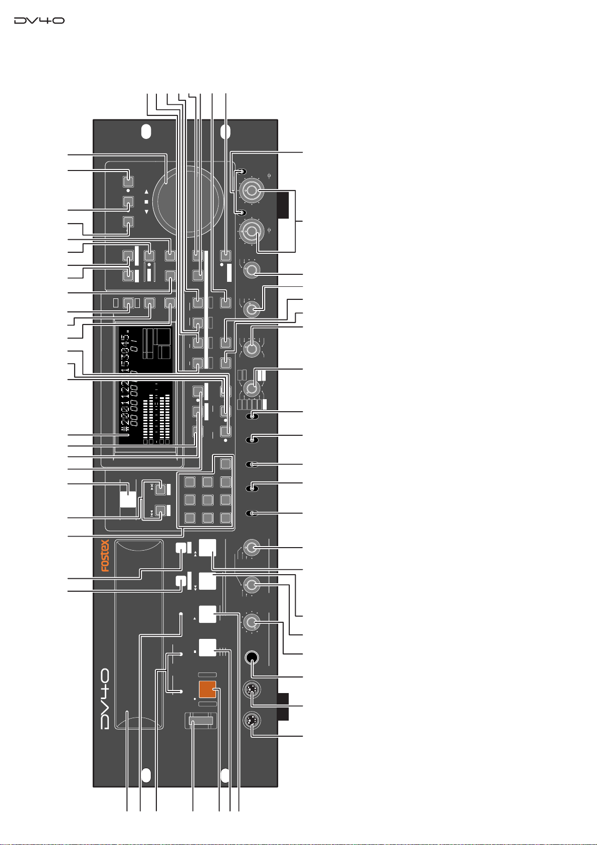
SHUTTLEJOGVARI PITCH
IN DSTOUT
symbol
SKIP/CURSOR
LOCATE
ENTER/YESEXIT/NO
DISP
MARGIN
FILE SEL
STORE
AUDIO EDIT UNDO
2
ABC
3
DEF
89
65
PQRS TUV WXYZ
GHI JKL MNO
TC RDY
INSLATE TONEMUTE
INSERT
OPEN/CLOSE
07
4
1
RESET
TIME
LEVEL
MEMORYCUE POINT
SETUP
NEW FILE
INPUT MON
MUTE REC
TONE REC
PREVIEW
HOLD
DIRECTORY
UTILITY
AUDIO RDY
TR1
SOURCE OUT
space
BY-
PASS
ON
OFF
MINMAX MAX
BY-
PASS
ON
OFF
MIN
VIDEO
WORD
INT
24H RUN
REC RUN
FREE RUN
EXT RUN
TR1 INPUT LEVELTR2 TR4TR3CLOCK
30DF
29.97
29.97DF2524
23.97
30
RSVD
PULL
48
44.1
48
(kHz)
192
44.1
16BIT
88.2
96
176.4
-0.1%
NORM
+0.1%
MULTI(4TR)
STEREO
MONO
DIGITAL
ANALOG
SDII
BWF
REMOTE
LOCAL
TC GEN MODE
CONTROL
UP/DOWN SAMPLING FREQ
TR MODE
INPUT
AUDIO FILE
FRAME RATE
DVD MASTER RECORDER
MONO
MAXMIN
POWER
TR4
TR3
TR2
TR1,3+2,4
TR3+4
TR1+2
TR1
LOCATE REC END
LOCATE ABS 0
F FWD
REWIND
PLAY
STOPRECORD
SOURCE PLAY
TC SETUP
LIST PLAYCHASE
EDIT
PHONES
HDDVD
DRIVE
KEYBOARD
MOUSE
DIGITAL
TR2
TR3
TR4
SHIFT
DISP
HMSF
432
1
-INT-
BWF
FORMAT
CLOCK
-0.1%
kHz
48
24
FS
BIT
PGM
ABS
∞
60
50
42 34 28 2018
12
8
6543210OL
+
-
TAPE MODE
24BIT
1
2
3
4
56
7
9-a
1011
12
13
14 15
16
17 18
20 21
22
19 23
24
25
26
28
29
31
33
35
41
36 38 403937
9-b 9-c
9-d
8-e
8-a
8-b
8-c
8-d
44 4543
30
27
32
52
515034494847
46
42
53
2. CONTROLS, INDICATORS & CONNECTORS
switch
]
switch
]
switch
]
switch
]
TR MODE
PULL UP/DOWN
SAMPLING FREQ
[
46.
key
])
PREVIEW
([
]
CUE POINT
[
28.
FRAME RATE
[
[
[
47.
48.
49.
key
])
key
])
TR 4
]/[
TR 3
]/[
PREVIEW
([
PREVIEW
]
([
key
]
]
OUT
IN
-
-
LOCATE
DEST
DEST
[
[
[
30.
31.
29.
keys
])
+
([-][
|<<, >>|]
connector
]
connector
]
SKIP/CURSOR
MOUSE
KEYBOARD
[
[
[
10.
11.
12.
13. FL display
switch
switch
]
TC GEN MODE
[
50.
key
]
UNDO
[
32.
key
]
MARGIN RESET/CLR
[
14.
]
switch
]
CLOCK
BYPASS ON/OFF
[
[
51.
52. Analog input signal controls
53.
key
])
key
])
TR 2
]/[
PREVIEW
([
]
key
]
OUT
-
AUDIO EDIT
SOURCE
[
[
34.
33.
key
]
key
]
DISP LEVEL
DISP TIME
[
[
15.
16.
key
])
TR 1
]/[
TONE REC
PREVIEW
([
]
([
]
IN
-
key
]
TC RDY
SLATE TONE
SOURCE
[
[
[
36.
37.
35.
key
])
key
])
DIRECTORY
([
UTILITY
]
([
]
key
]
SHIFT
SETUP
FILE SEL
[
[
[
19.
17.
18.
key
]
AUDIO RDY - INSERT
[
38.
key
]
VARI PITCH
[
20.
key
]
key
])
key
]
MUTE REC
([
]
MUTE
AUDIO RDY - NEW FILE
INPUT MON
[
[
[
39.
40.
41.
key
]
key
]
key
]
SHUTTLE
JOG
ENTER/YES
[
[
[
21.
22.
23.
switch
]
switch
]
switch
]
CONTROL
AUDIO FILE
INPUT
[
[
[
42. Alphanumeric keys
43.
44.
45.
key
])
key
])
PREVIEW
([
HOLD
]
key
]
EXIT/NO
[
24.
MEMORY
[
25. Jog Dial
26.
([
]
STORE
[
27.
2-1. TOP PANEL SECTION
8
switch
]
POWER
[
1.
2. Disk tray
key
])
indicator
)]
indicator
]
TC SETUP
([
DVD/HD
]
(
TAPE MODE
CHASE
DRIVE
[
[
[
4.
5.
3.
key
])
key
key
]
EDIT
([
]
LIST PLAY
[
6.
]
RECORD
[
OPEN/CLOSE
[
8-a.
7.
8. Transport keys
key
key
]
]
STOP
PLAY
[
[
8-b.
8-c.
key
]
key
]
REWIND
F.FWD
[|<<
[>>|
8-d.
8-e.
9. Monitor section
jack
PHONES
9-a.
Mono track select switch
9-b. Headphones level control
9-c. Monitor track select switch
9-d.
Page 9

+4dBu
-10dBV
+4dBu
-10dBV
+4dBu
-10dBV
+4dBu
-10dBV
TR4
TR2
TR3 TR1
TR3 TR1BAL [+4dBu]
BAL [+4dBu]
UNBAL
[-10dBV]
UNBAL
[-10dBV]
TR4
TR2
BAL [+4dBu]
BAL [+4dBu]
UNBAL
[-10dBV]
UNBAL
[-10dBV]
OUTPUT
THRU
INPUT
10/100
LINK
TX/RX
TR4-3 TR2-1
TR2
TR1
TR1
TR2
1:GND
2:HOT
3:COLD
192kHz
176.4kHz
INPUT
OUTPUT
INPUT
75Ω
ON
OFF
INPUT
75Ω
ON
OFF
TR4-3 TR2-1
TR2
TR1
THRU
THRU OUTPUT
AC IN
1: GND 2: HOT 3: COLD
1: GND 2: HOT 3: COLD
1: GND
2: HOT
3: COLD
15P-REMOTE
9P-REMOTE
GPI
DIGITAL OUTPUT
WORD
TIME CODE
ETHERNET
ANALOG INPUT BALANCED
ANALOG OUTPUT
DIGITAL INPUT
VIDEO
FAN
HI
LO
2-A
1-A
1-B
1-C
1-D
2-B
2-C
34
5-A 5-B 6-A 6-C
6-B
78-A 8-B 8-C 8-D
9-A
9-B
10
11
12
Service Manual
connector
connector
GPI INPUT
GPI OUTPUT
9-A.
9-B.
9. GPI input/output connectors
11. 15-pin remote connector
12. FAN switch
10. 9-pin remote connector
5-A. DIGITAL INPUT connectors
5-B. DIGITAL OUTPUT connectors
6-A. VIDEO INPUT connector
6-B. 75Ω ON/OFF switch
5. Digital input/output section
6. Video clock section
6-C. VIDEO THRU connector
7. AC IN connector
8. Word clock section
8-A. WORD INPUT connector
8-B. 75Ω ON/OFF switch
8-C. WORD THRU connector
8-D. WORD OUT connector
2-2. REAR PANEL SECTION
(TR1 THROUGH TR4)
1-A. ANALOG INPUT (BALANCED) connectors
1. Analog input/output section
(TR1 THROUGH TR4)
(TR1 THROUGH TR4)
1-B. Input level switches
1-C. ANALOG OUTPUT (BAL) connectors
1-D. ANALOG OUTPUT (UNBAL) connectors
2. Time code input/output section
2-A. TIME CODE INPUT connector
2-B. TIME CODE THRU connector
2-C. TIME CODE OUTPUT connector
3. Expansion slot
4. ETHERNET port
9
Page 10
Service Manual
3. SOFTWARE UPDATE
There are flash ROMs mounted on the CPU Module PCB assy (16M), Display PCB assy (8M inside the Display CPU)
and Ether Card PCB assy (8M). The DV40 software can be updated using a CD-ROM or DVD-RAM disk put into the
DV40 internal DVD-RAM drive. Please refer to the following explanation for correct software updating procedures.
3-1. Required Tools
The following tools / equipment are required to update the DV40 software.
1. IBM PC/AT compatible or Macintosh computer
2. CD-R / RW drive with CD burning application software or DVD-RAM drive with UDF formatting software
3. CD-R / CD-RW disk or DVD-RAM disk
4. A Utility software to extract WinZip compressed software update file
3-2. Software Updating Procedures
The following explanation presumes that the WinZip compressed software update file is correctly sent to you via email
and is copied into your computer.
3-2-1. When using CD-R / RW drive & disk
1. Using a utility software, extract a WinZip compressed software update file “DV40VXXX.zip”. (XXX indicates
the software version number.) There are three files extracted as follow.
1) DV40dXXX.HEX (XXX: software version number) for Display PCB
2) dv40eXXX.mot (XXX: software version number) for Ether Card PCB
3) dv40mXXX.mot (XXX: software version number) for Main PCB (CPU Module PCB)
2. Boot up a CD-R burning application software, insert a blank CD-R or CD-RW disk into a CD-R / RW drive
connected to a PC and create a CD-ROM disk in which the above software update files are included. Please
remember that the software update files must be placed in the 1st directory tree and not be included in a folder.
3. After burning, take out the CD-ROM disk with software update files from the drive.
4. Power on DV40, press the OPEN/CLOSE key to open the disk tray and put the disk into the DVD-RAM drive.
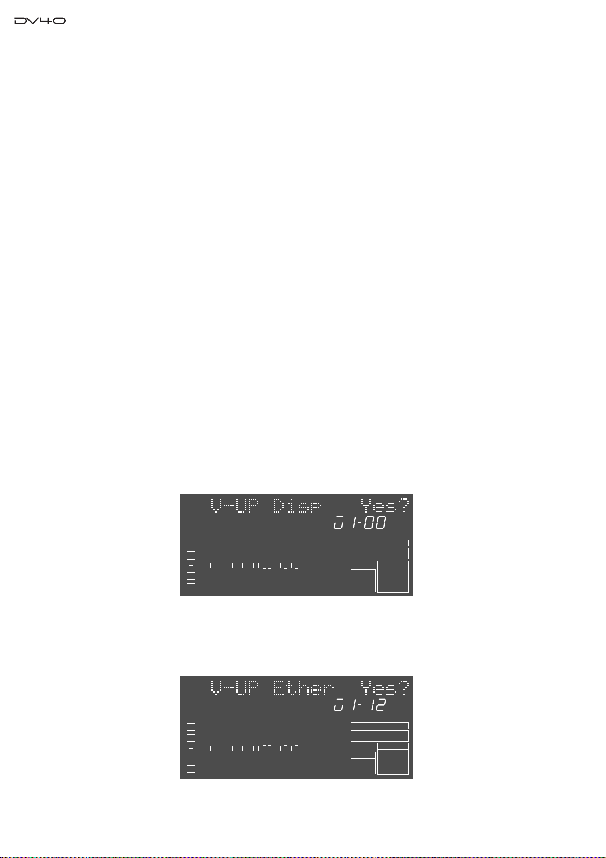
5. “Scan Disk!” and “CD” are displayed. Then, if DV40 properly finds the software update files on the CD-ROM
disk, “V-UP Disp Yes?” will appear on the DV40 FL display shown below. Also the software version number of
the update file is displayed. The example below indicates that there is a “V1.00” software file on the CD-ROM
disk.
BIT
1
2
50
42 34 28 2018
60
∞
3
4
8
12
6543210OL
FS
kHz
-0.1%
FORMAT
BWF
48
24
CLOCK
-INT-
6. Press the ENTER/YES key to update the Display PCB software. While updating the software, the FL display is
blacked out for about 1 minutes but do not power off DV40 and leave it until the next message shows up.
7. After the completion, “V-UP Ether Yes?” and the software version number of the update file will appear on the
DV40 FL display. Press the ENTER/YES key to update the Ether Card PCB assy software. The example below
indicates that there is a “V1.12” software file on the CD-ROM disk.
BIT
1
2
50
42 34 28 2018
60
∞
3
4
8
12
6543210OL
FS
kHz
-0.1%
FORMAT
BWF
48
24
CLOCK
-INT-
8. While updating, “Transfer file”, “Erase...” and “Program...” messages are displayed. After the completion with
“Completed!” message, “V-UP Main Yes?” and the software version number of the update file will appear on the
10
Page 11

Service Manual
DV40 FL display. Press the ENTER/YES key to update the Main PCB assy (CPU Module PCB) software. The
example below indicates that there is a “V1.12” software file on the CD-ROM disk.
BIT
1
2
50
42 34 28 2018
60
∞
3
4
8
12
6543210OL
FS
kHz
-0.1%
FORMAT
BWF
48
24
CLOCK
-INT-
9. While updating, “Erase ROM” and “Write PGM” messages are displayed. After the completion with “Completed!”
message, DV40 goes back to the normal display.
10. Power off and then back on DV40.
11. Confirm each software version by SETUP mode (Main and Ether Card PCB) and special mode (Display PCB)
explained later.
3-2-2. When using DVD-RAM drive & disk
1. Using a utility software, extract a WinZip compressed software update file “DV40VXXX.zip”. (XXX indicates
the software version number.) There are three files extracted as follow.
1) DV40dXXX.HEX (XXX: software version number) for Display PCB
2) dv40eXXX.mot (XXX: software version number) for Ether PCB
3) dv40mXXX.mot (XXX: software version number) for Main PCB (CPU Module PCB)
2. Boot up a DVD-RAM disk formatting software, insert a blank DVD-RAM disk into an ATAPI or SCSI DVDRAM drive connected to a PC, format the disk by UDF1.5 and copy the above software update files to the DVDRAM disk. Please remember that the software update files must be placed in the 1st directory tree and not be
included in a folder.
3. After copying, take out the DVD-RAM disk with software update files from the drive.
4. Power on DV40, press the OPEN/CLOSE key to open the disk tray and put the disk into the DVD-RAM drive.
5. “Scan Disk!” and “CD” are displayed. Then, if DV40 properly finds the software update file on the DVD-RAM
disk, “V-UP Disp Yes?” will appear on the DV40 FL display. Also the software version number of the update file
is displayed.
6. Press the ENTER/YES key to update the Display PCB software. While updating the software, the FL display is
blacked out for about 1 minutes but do not power off DV40 and leave it until the next message shows up.
7. After the completion, “V-UP Ether Yes?” and the software version number of the update file will appear on the
DV40 FL display. Press the ENTER/YES key to update the Ether PCB assy software.
8. While updating, “Transfer file”, “Erase...” and “Program...” are displayed. After the completion with “Completed!”
message, “V-UP Main Yes?” and the software version number of the update file will appear on the DV40 FL
display. Press the ENTER/YES key to update the Main PCB assy (CPU Module PCB) software.
9. While updating, “Erase ROM” and “Write PGM” are displayed. After the completion with “Completed!” message,
DV40 goes back to the normal display.
10. Power off and then back on DV40.
11. Confirm each software version by SETUP mode (Main and Ether Card PCB) and special mode (Display PCB)
explained later.
[NOTE]
Instead of using the DVD-RAM drive connected to a PC, the DVD-RAM disk can be formatted using the Format menu
in the DV40 Utility mode ([SHIFT] + [SETUP]). In such a case, regardless of Normal or Tape formatting mode, simply
format the disk. The important thing is to place the software files in the 1st directory tree.
[CAUTION]
1. Please make sure to power off and then back on DV40 and initialize it (See page 14.) after updating the software.
2. When using a DVD-RAM disk for updating the software, please make sure to format it by UDF1.5. If the disk is
formatted by UDF2.0, it might not be correctly recognized by a Macintosh computer.
3. Please remember that all three software files are not necessarily sent to you every time. For example, there is a
case that only the software for Main PCB (CPU Module PCB) and Ether Card PCB are sent to you.
11
Page 12
Service Manual
4. SERVICE MODE
Various Optional Menus are available on the DV40 Service Mode. Please utilize them while servicing the unit.
4-1. Putting DV40 into Service Mode
The way to put DV40 into Service Mode is to press the [SETUP] key while holding down the [STOP] key. With this
operation, optional menus “Self Check Sure?”, “Memory Initial?” and “Flash ROM?” will be additionally displayed
between the “Running Time” and “RTC Adjust?” normal Setup menus.
User Setup Save?
Mute Rec?
Tone Rec?
TCP/IP Setup?
User Setup Load?
C.W.
Version Main
Self Check Sure?
Version Ethernet
[STOP]
[SETUP]
+
Running Time
RTC Adjust?
Contast?
Memory Initial ?
GPI?
Peak Hold?
RS422 Setp?
Panel Lock?
C.C.W.
XXX : Normal SETUP menu
XXX : OPTINAL menu
Flash ROM?
Skip Mode?
Ref.Level?
D.IN Tr.?
D.Out?
Diagnoses?Auto EE MD?
Rotate the JOG dial, select a required optional menu and press the [ENTER/YES] key to execute.
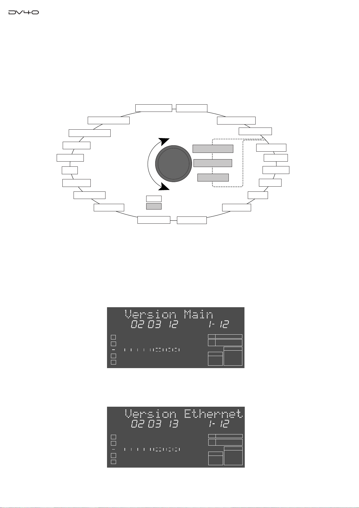
4-2. Software Version
4-2-1. Software Version of Flash ROM on CPU Module (Main PCB)
The software version can be confirmed by the normal SETUP menu. Just press the [SETUP] key and rotate the jog dial.
The example below indicates that the software version is V1.12 and the programming date is March 12, 2002.
SETUP
YMD
BIT
1
2
50
42 34 28 2018
60
∞
3
4
8
12
6543210OL
FS
kHz
-0.1%
FORMAT
BWF
48
24
CLOCK
-INT-
4-2-2. Software Version of Flash ROM on Ether PCB
The software version can be confirmed by the normal SETUP menu. Just press the [SETUP] key and rotate the jog dial.
The example below indicates that the software version is V1.12 and the programming date is March 13, 2002.
SETUP
YMD
BIT
1
2
50
42 34 28 2018
60
∞
3
4
8
12
6543210OL
FS
kHz
-0.1%
FORMAT
BWF
48
24
CLOCK
-INT-
12
Page 13
Service Manual
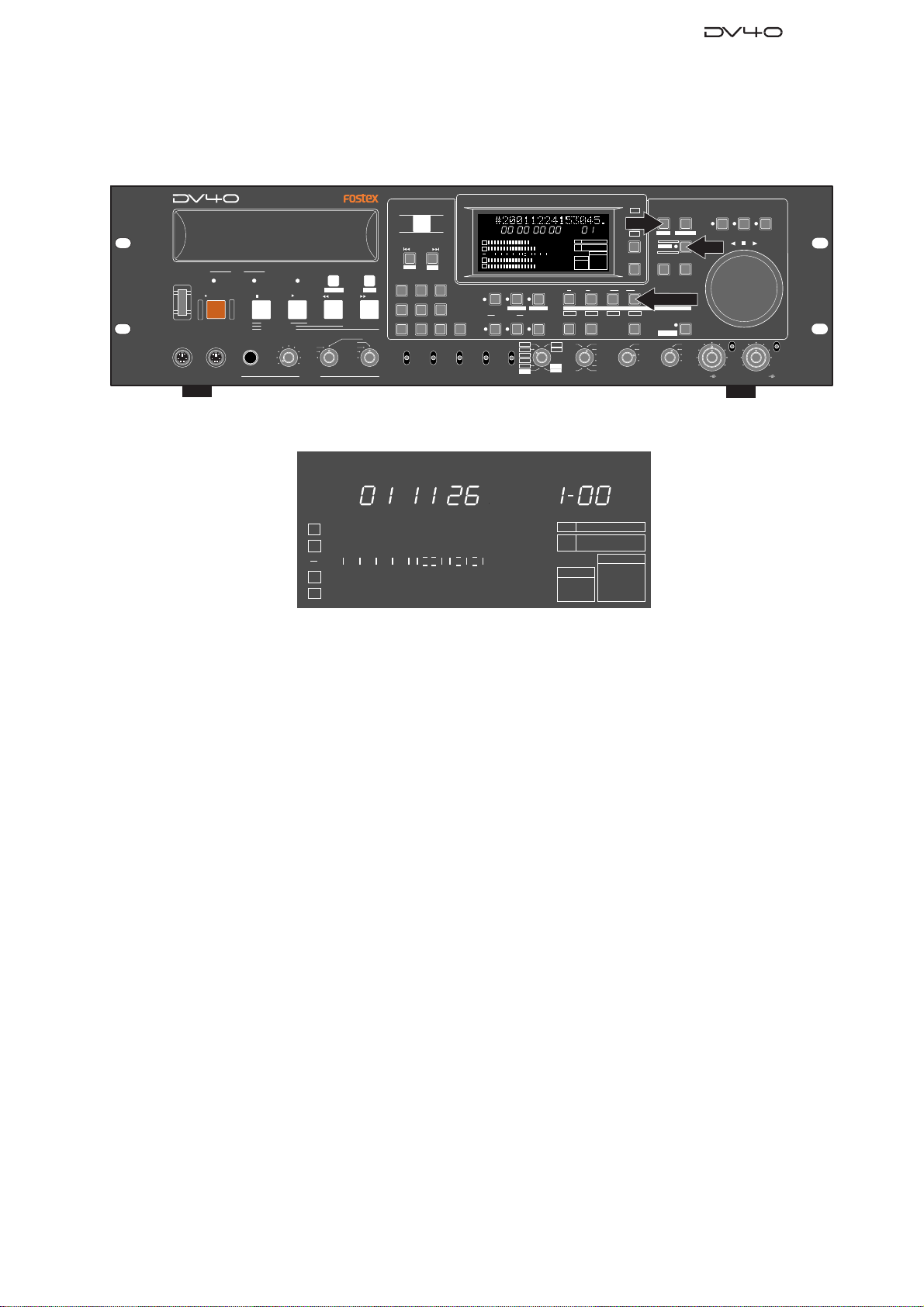
4-2-3. Software Version of Flash ROM on Display PCB
The way to check the software version of Flash ROM on the Display PCB is different from the one on the CPU Module
PCB (Main PCB) or Ether Card PCB. As indicated in the drawing below, press the [SETUP], [SHIFT] and [DEST
OUT] at a time.
POWER
KEYBOARD
DVD MASTER RECORDER
DRIVE
MOUSE
HDDVD
STOPRECORD
SOURCE PLAY
LOCATE ABS 0
LOCATE REC END
TAPE MODE
PLAY
MAXMIN
TR1,3+2,4
PHONES
LIST PLAYCHASE
TC SETUP
REWIND
TR4
TR3
TR3+4
TR2
TR1+2
TR1
EDIT
F FWD
MONO
OPEN/CLOSE
SKIP/CURSOR
-
space
1
2
GHI JKL MNO
4
PQRS TUV WXYZ
89
REMOTE
LOCAL
CONTROL
AUDIO FILE
+
ABC3DEF
65
BWF
SDII
ANALOG
DIGITAL
DISP
FILE SEL
SETUP
TIME
HMSF
ABS
1
2
50
42 34 28 2018
60
∞
3
4
INPUT MON
MUTE REC
AUDIO RDY
INSERT
NEW FILE
symbol
07
MONO
+0.1%
STEREO
NORM
MULTI(4TR)
-0.1%
PULL
TR MODE
UP/DOWN SAMPLING FREQ
INPUT
PGM
kHz
-0.1%
8
12
6543210OL
FORMAT
BWF
INSLATE TONEMUTE
SOURCE OUT
TONE REC
TR1
TC RDY
AUDIO EDIT UNDO
176.4
96
88.2
48
44.1
48
30
192
24BIT
(kHz)
16BIT
44.1
RSVD
FRAME RATE
SETUP
DIRECTORY
UTILITY
DISP
LEVEL
24FSBIT
48
CLOCK
-INT-
IN DSTOUT
TR3
TR2
30DF
29.97
29.97DF
25
24
23.97
MARGIN
RESET
PREVIEW
LOCATE
TC GEN MODE
DEST-OUT/TR4
TR4
24H RUN
REC RUN
FREE RUN
EXT RUN
STORE
SHIFT
SHIFT
ENTER/YESEXIT/NO
MEMORYCUE POINT
HOLD
INT
WORD
VIDEO
DIGITAL
MIN
TR1 INPUT LEVELTR2 TR4TR3CLOCK
BY-
PASS
ON
OFF
MINMAX MAX
SHUTTLEJOGVARI PITCH
ON
OFF
BY-
PASS
The example below indicates that the software version is V1.00 and the programming date is November 26, 2001.
YMD
BIT
1
2
60
∞
50
42 34 28 2018
8
12
6543210OL
3
4
FS
kHz
-0.1%
FORMAT
BWF
48
24
CLOCK
-INT-
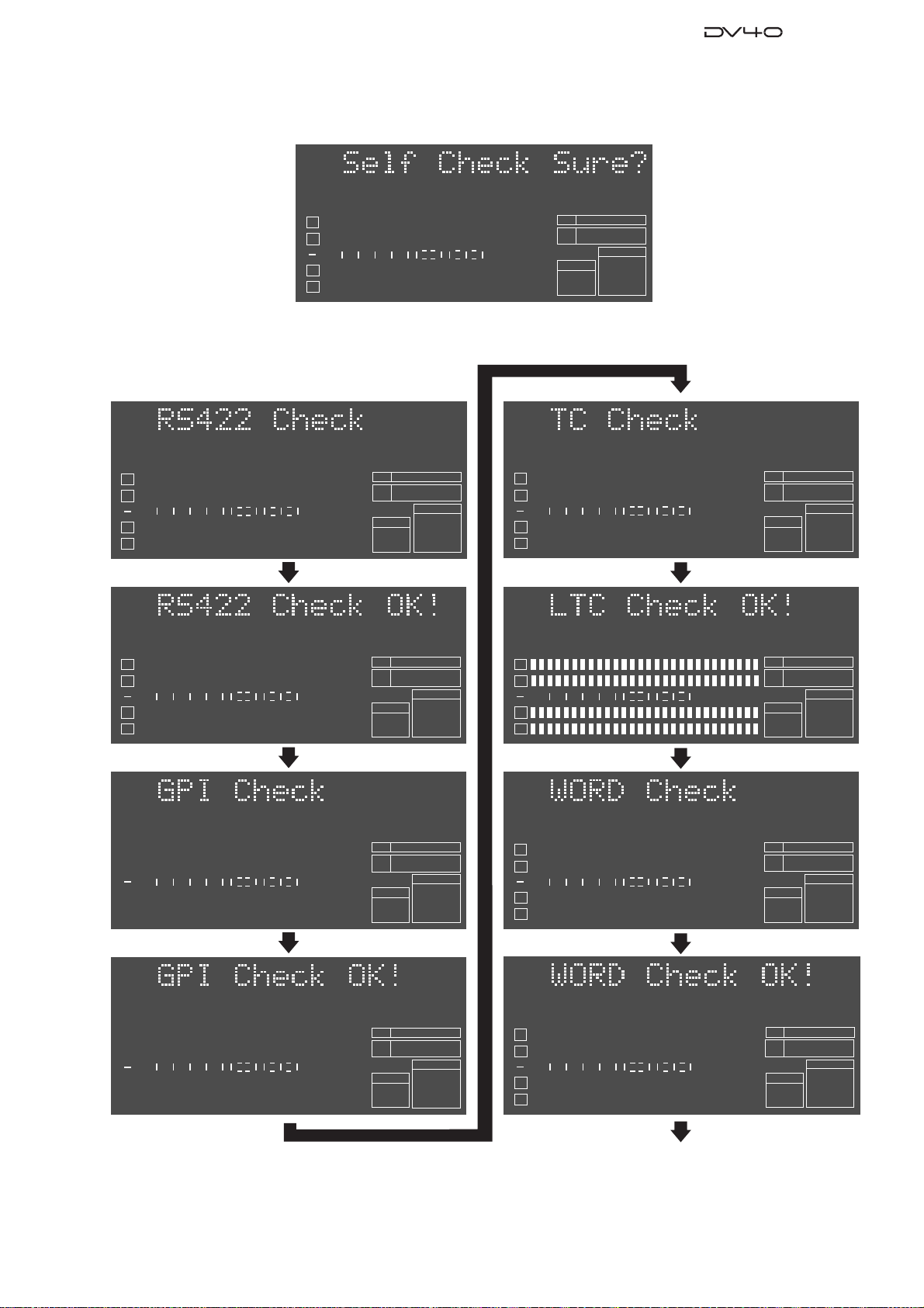
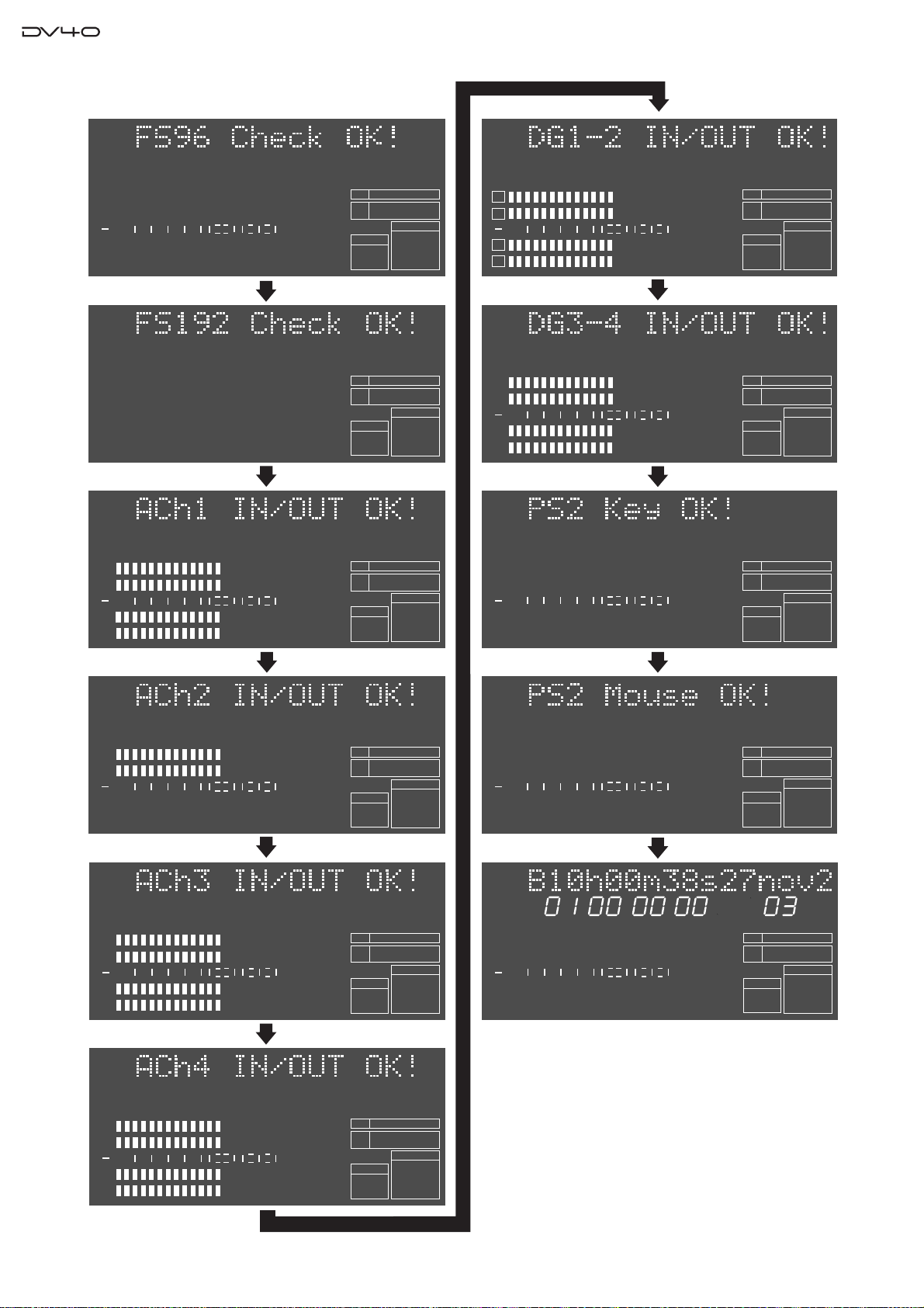
4-3. Self Check Mode
The Self Check mode helps you check if DV40 works properly or not and which circuits are causing a problem. In this
mode, the following circuit are tested in order.
• RS422 9-pin circuit
• GPI circuit
• TC circuit
• WORD circuit (Fs: 48kHz)
• WORD circuit (Fs: 96kHz)
• WORD circuit (Fs: 192kHz)
• ANALOG CH1 circuit
• ANALOG CH2 circuit
• ANALOG CH3 circuit
• ANALOG CH4 circuit
• DIGITAL CH1/2 circuit
• DIGITAL CH3/4 circuit
• Keyboard
• Mouse
13
Page 14

Service Manual
4-3-1. Preparation
Before executing the Self Check mode, prepare the following cables, etc and connect them as indicated below.
• 7 x XLR (male) - XLR (female) balanced cables
ANALOG IN CH1 - ANALOG OUT CH1
ANALOG IN CH2 - ANALOG OUT CH2
ANALOG IN CH3 - ANALOG OUT CH3
ANALOG IN CH4 - ANALOG OUT CH4
DIGITAL IN CH1/2 - DIGITAL OUT CH1/2
DIGITAL IN CH3/4 - DIGITAL OUT CH3/4
TC IN - TC OUT
• 1 x BNC - BNC cable
WORD IN - WORD OUT
• 1 x D-SUB 9-pin male connector (Pin-2 & 8 / Pin 3 & 7 are shortened.)
To RS-422 9-pin connector
• 1 x MIDI cable
GPI IN - GPI OUT
• PS/2 keyboard
To KEYBOARD connector
• PS/2 mouse
To MOUSE connector
<Connection on DV40 Front Panel side>
DVD MASTER RECORDER
TC SETUP
REWIND
LIST PLAYCHASE
EDIT
F FWD
MONO
TR4
TR3
TR2
REMOTE
TR1
LOCAL
CONTROL
PS/2 keyboard
POWER
KEYBOARD
DRIVE
MOUSE
PS/2 mouse
HDDVD
STOPRECORD
SOURCE PLAY
LOCATE ABS 0
LOCATE REC END
TAPE MODE
PLAY
MAXMIN
TR1,3+2,4
PHONES
TR3+4
TR1+2
<Connection on DV40 Rear Panel side>
XLR balanced cable
XLR balanced cable
ANALOG INPUT BALANCED
TR3 TR1
+4dBu
-10dBV
TR4
+4dBu
-10dBV
XLR balanced cable
1: GND 2: HOT 3: COLD
+4dBu
-10dBV
TR2
+4dBu
XLR balanced cable
-10dBV
ANALOG OUTPUT
TR3 TR1BAL [+4dBu]
UNBAL
[-10dBV]
BAL [+4dBu]
TR4
UNBAL
[-10dBV]
1: GND 2: HOT 3: COLD
BAL [+4dBu]
BAL [+4dBu]
UNBAL
[-10dBV]
UNBAL
[-10dBV]
TIME CODE
INPUT
THRU
TR2
OUTPUT
1: GND
2: HOT
3: COLD
OPEN/CLOSE
SKIP/CURSOR
-
space
ABC3DEF
1
2
GHI JKL MNO
4
PQRS TUV WXYZ
89
BWF
SDII
AUDIO FILE
XLR balanced cable
15P-REMOTE
+
65
ETHERNET
ANALOG
DIGITAL
10/100
LINK
TX/RX
DISP
TIME
HMSF
ABS
1
2
50
42 34 28 2018
60
∞
3
4
INPUT MON
MUTE REC
AUDIO RDY
INSERT
NEW FILE
symbol
07
MONO
+0.1%
STEREO
NORM
MULTI(4TR)
-0.1%
PULL
TR MODE
BNC cable
UP/DOWN SAMPLING FREQ
DIGITAL INPUT
TR4-3 TR2-1
TR2
DIGITAL OUTPUT
TR4-3 TR2-1
TR2
BNC cable
1:GND
TR1
2:HOT
TR2
3:COLD
9P-REMOTE
INPUT
PGM
kHz
-0.1%
8
12
6543210OL
FORMAT
BWF
INSLATE TONEMUTE
SOURCE OUT
TONE REC
TR1
TC RDY
AUDIO EDIT UNDO
176.4
96
88.2
48
44.1
48
192kHz
176.4kHz
30
192
24BIT
(kHz)
16BIT
44.1
RSVD
FRAME RATE
TR1
INPUT
TR1
INPUT
GPI
INPUT
24FSBIT
48
CLOCK
-INT-
TR2
30DF
29.97
29.97DF
25
24
23.97
75Ω
ON
75Ω
ON
BNC cable
OUTPUT
DISP
LEVEL
MARGIN
RESET
IN DSTOUT
PREVIEW
TR3
LOCATE
TC GEN MODE
VIDEO
OFF
WORD
OFF
SETUP
UTILITY
TR4
STORE
24H RUN
REC RUN
FREE RUN
EXT RUN
FAN
THRU
HI
THRU OUTPUT
FILE SEL
DIRECTORY
SHIFT
ENTER/YESEXIT/NO
MEMORYCUE POINT
HOLD
INT
WORD
VIDEO
DIGITAL
MIN
TR1 INPUT LEVELTR2 TR4TR3CLOCK
LO
SHUTTLEJOGVARI PITCH
ON
ON
OFF
MINMAX MAX
OFF
BY-
PASS
BY-
PASS
AC IN
MIDI cable
14
D-SUB 9-pin male connector
with shorted pins
Pin-2 (Transmit A) & Pin-8 (Receive A)
Pin-3 (Receive B) & Pin-7 (Transmit B)
Page 15
Service Manual
4
3
2
1
24
BIT
∞
60
50
42 34 28 2018
12
8
6543210OL
BWF
FORMAT
kHz
48
FS
-INT-
CLOCK
4-3-2. Executing Self Check mode
Press the [ENTER/YES] key while “?” flashes.
SETUP
BIT
1
2
60
∞
50
42 34 28 2018
8
12
6543210OL
3
4
If DV40 works properly, the followings appear on the FL display and it automatically goes back to the normal display.
FS
kHz
-0.1%
FORMAT
BWF
48
24
CLOCK
-INT-
1
2
3
4
1
2
3
4
SETUP
1
2
3
4
60
∞
60
∞
60
∞
50
42 34 28 2018
50
42 34 28 2018
50
42 34 28 2018
DIGITAL
DIGITAL
DIGITAL
8
12
8
12
8
12
6543210OL
6543210OL
6543210OL
BIT
FS
kHz
FORMAT
BWF
BIT
FS
kHz
FORMAT
BWF
BIT
FS
kHz
FORMAT
BWF
24
96
CLOCK
-INT-
24
96
CLOCK
-INT-
24
96
CLOCK
-EXT-
DIGITAL
1
DIGITAL
2
60
∞
50
42 34 28 2018
8
12
6543210OL
3
4
DIGITAL
1
2
60
∞
50
42 34 28 2018
8
12
6543210OL
3
4
1
2
60
∞
50
42 34 28 2018
8
12
6543210OL
3
4
BIT
FS
kHz
FORMAT
BWF
BIT
FS
kHz
FORMAT
BWF
BIT
FS
kHz
FORMAT
BWF
48
24
CLOCK
24
CLOCK
24
CLOCK
96
-INT-
96
-INT-
-INT-
SETUP
1
DIGITAL
2
60
∞
50
42 34 28 2018
8
12
6543210OL
3
4
BIT
FS
kHz
FORMAT
BWF
24
96
CLOCK
-EXT-
DIGITAL
Continue to next page
15
Page 16
Service Manual
1
DIGITAL
2
60
∞
50
42 34 28 2018
8
12
6543210OL
3
4
DIGITAL
1
2
3
4
DIGITAL
1
2
60
∞
50
42 34 28 2018
8
12
6543210OL
3
4
BIT
FS
kHz
FORMAT
BWF
BIT
FS
kHz
FORMAT
BWF
BIT
FS
kHz
FORMAT
24
CLOCK
24
CLOCK
24
CLOCK
96
-INT-
-INT-
-INT-
192
192
1
2
50
42 34 28 2018
60
∞
3
4
1
2
50
42 34 28 2018
60
∞
3
4
1
2
50
42 34 28 2018
60
∞
3
4
DIGITAL
DIGITAL
DIGITAL
8
12
8
12
8
12
6543210OL
6543210OL
6543210OL
BIT
FS
kHz
-0.1%
FORMAT
BWF
BIT
FS
kHz
-0.1%
FORMAT
BWF
BIT
FS
kHz
FORMAT
BWF
24
CLOCK
24
CLOCK
24
CLOCK
192
-INT-
96
-INT-
96
-INT-
1
DIGITAL
2
60
∞
50
42 34 28 2018
8
12
6543210OL
3
4
DIGITAL
1
2
60
∞
50
42 34 28 2018
8
12
6543210OL
3
4
DIGITAL
1
2
60
∞
50
42 34 28 2018
8
12
6543210OL
3
BIT
FS
kHz
FORMAT
BIT
FS
kHz
FORMAT
BIT
FS
kHz
FORMAT
24
CLOCK
24
CLOCK
24
CLOCK
-INT-
-INT-
-INT-
192
192
192
1
2
50
42 34 28 2018
60
∞
3
4
LTC
1
2
50
42 34 28 2018
60
∞
3
4
DIGITAL
8
12
6543210OL
HMSF
DIGITAL
8
12
6543210OL
PGM
BIT
FS
kHz
FORMAT
BWF
DVD
BIT
FS
kHz
FORMAT
BWF
DVD
SDII
24
96
CLOCK
-INT-
24
48
CLOCK
-INT-
-EXT-
WORD
CD
VIDEO
DIGITAL
4
16
Page 17
Service Manual
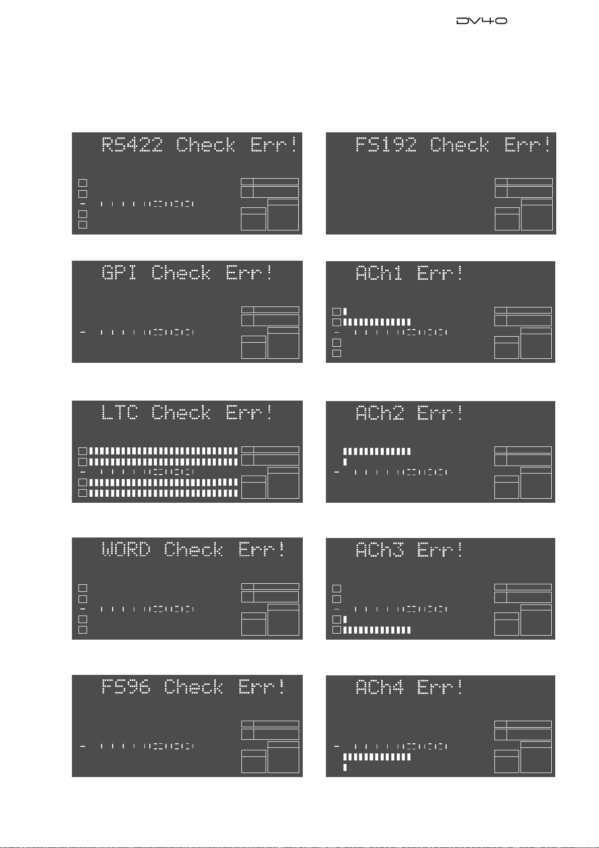
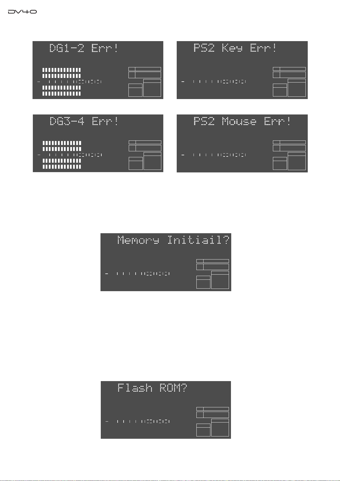
4-3-2. Error display examples
The followings are error display examples. Please remember that pressing the [ENTER/YES] key will retry each
checking item and pressing the [EXIT/NO] key will skip each checking item and go on to the next one.
• Error on RS422 circuitry
1
2
50
42 34 28 2018
60
∞
3
4
DIGITAL
• Error on GPI circuitry
SETUP
DIGITAL
1
2
50
42 34 28 2018
60
∞
3
4
• Error on TC circuitry
8
12
8
12
6543210OL
6543210OL
BIT
FS
kHz
FORMAT
BWF
BIT
FS
kHz
FORMAT
BWF
24
96
CLOCK
-INT-
24
96
CLOCK
-EXT-
DIGITAL
• Error on WORD circuitry (192kHz)
1
DIGITAL
2
3
4
BIT
FS
kHz
FORMAT
BWF
• Error on Analog input & output circuit (CH1)
1
DIGITAL
2
60
∞
50
42 34 28 2018
8
12
6543210OL
3
4
BIT
FS
kHz
FORMAT
BWF
• Error on Analog input & output circuit (CH2)
24
CLOCK
24
CLOCK
-INT-
192
-INT-
192
1
DIGITAL
2
60
∞
50
42 34 28 2018
8
12
6543210OL
3
4
• Error on WORD circuitry (48kHz)
1
2
60
∞
50
42 34 28 2018
8
12
6543210OL
3
4
• Error on WORD circuitry (96kHz)
1
2
50
42 34 28 2018
60
∞
3
4
DIGITAL
8
12
6543210OL
BIT
FS
kHz
FORMAT
BWF
BIT
FS
kHz
FORMAT
BWF
BIT
FS
kHz
FORMAT
BWF
48
24
CLOCK
24
CLOCK
24
CLOCK
96
-INT-
-INT-
96
-INT-
1
DIGITAL
2
60
∞
50
42 34 28 2018
8
12
6543210OL
3
4
BIT
FS
kHz
FORMAT
BWF
• Error on Analog input & output circuit (CH3)
1
DIGITAL
2
60
∞
50
42 34 28 2018
8
12
6543210OL
3
4
BIT
FS
kHz
FORMAT
BWF
• Error on Analog input & output circuit (CH4)
1
DIGITAL
2
60
∞
50
42 34 28 2018
8
12
6543210OL
3
4
BIT
FS
kHz
FORMAT
BWF
24
CLOCK
-INT-
24
CLOCK
-INT-
24
CLOCK
-INT-
192
192
192
17
Page 18
Service Manual
• Error on DIGITAL input and output circuitry (CH 1/2) • Error on PS2 keyboard circuitry
DIGITAL
1
DIGITAL
1
2
2
50
42 34 28 2018
60
50
42 34 28 2018
∞
60
∞
3
3
4
4
8
12
8
12
6543210OL
6543210OL
BIT
BIT
FS
FS
kHz
kHz
FORMAT
FORMAT
BWF
BWF
24
24
CLOCK
CLOCK
96
-INT-
-INT-
192
1
2
50
42 34 28 2018
60
∞
3
4
DIGITAL
8
12
6543210OL
BIT
FS
kHz
FORMAT
BWF
24
96
CLOCK
-INT-
• Error on DIGITAL input and output circuitry (CH 3/4) • Error on PS2 mouse circuitry
1
DIGITAL
2
60
∞
50
42 34 28 2018
8
12
6543210OL
3
4
BIT
FS
kHz
FORMAT
BWF
24
96
CLOCK
-INT-
1
2
50
42 34 28 2018
60
∞
3
4
DIGITAL
8
12
6543210OL
BIT
FS
kHz
FORMAT
BWF
DVD
24
96
CLOCK
-INT-
4-4. Memory Initialize
Executing this menu initializes the setting in each SETUP menu and MEMORY (time information of Last Play, Last
Record In / Out and Memory # 04 ~ 99). To do so, press the [ENTER/YES] key while “?” flashes.
SETUP
1
DIGITAL
2
60
∞
50
42 34 28 2018
8
12
6543210OL
3
4
BIT
FS
kHz
FORMAT
BWF
48
24
CLOCK
-INT-
4-5. Flash ROM
There is a Flash ROM Card PCB prepared for the CPU Module and Ether Card PCBs. The Flash ROM Card PCB is
used if something wrong happens while updating the software (e.g. power shutdown, blackout). The Flash ROM Card
PCB allows to boot up DV40, copy the system software in the Flash ROM Card PCB to the Flash ROM on the CPU
Module and Ether Card PCBs using this “Flash ROM” Service Menu. Furthermore, you can rewrite the program inside
the Flash ROM on the Flash ROM Card PCB. In other words, by rewriting the program, only one Flash ROM PCB can
work for both the CPU Module and Ether Card PCBs. Refer to the following procedures.
SETUP
1
DIGITAL
2
60
∞
50
42 34 28 2018
8
12
6543210OL
3
4
BIT
FS
kHz
FORMAT
BWF
48
24
CLOCK
-INT-
18
Page 19
Service Manual
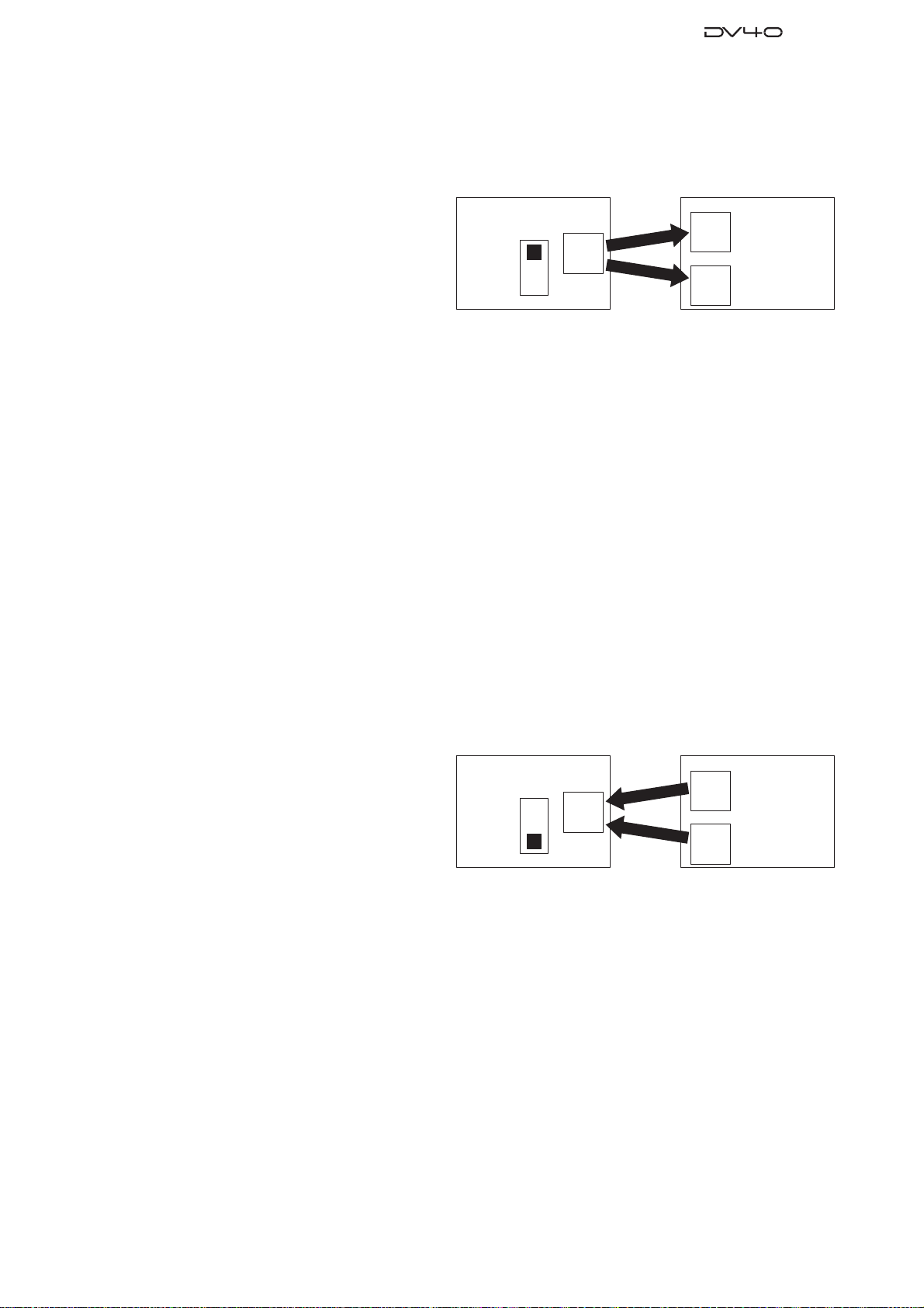
4-5-1. Boot Up using Flash ROM Card PCB & Rewriting Flash ROM Program on CPU Module
& Ether Card PCBs
1. Power off DV40 and disconnect the AC cable from the AC IN socket.
2. Open up the top cover.
3. Set the SW S1 on the Flash ROM PCB to “EXT
(FLASH)” side and plug it into either the PCB
assy which cannot be correctly booted up (CPU
Module PCB: J4 50-pin connector, Ether Card
PCB: J300 50-pin connector).
4. Connect the AC cable and power on DV40.
In this condition, DV40 is booted up using the
program inside the Flash ROM on the Flash ROM PCB.
5. Put DV40 into the Service Mode by pressing the [SETUP] key while holding down the [STOP] key and select the
“Flash ROM?” menu.
6. While “?” flashes, press the [ENTER/YES] key.
7. “FlashWrite Sure?” appears on the FL display. Press the [ENTER/YES] key again. The message “ERASE ROM”
and “Write PGM” appear on the FL display while copying the program.
BOOTUP
Flash ROM Card PCB
SW S1
EXT
(FLASH)
INT
Flash
ROM
Copy
Program.
Copy
Program.
CPU Module PCB
Flash
ROM
Ether Card PCB
Flash
ROM
DV40
With “Completed!” message, the program inside the Flash ROM on the Flash ROM Card PCB has been successfully
copied to the Flash ROM on either the CPU Module or Ether Card PCB.
8. After confirming that DV40 is correctly booted up, copy the latest software to the CD-ROM or DVD-RAM disk
and update accordingly.
4-5-2. Rewriting Flash ROM Program on Flash ROM Card PCB
[NOTE]
In order to rewrite the Flash ROM program on the Flash ROM Card PCB, preparing DV40 which is booted up
correctly is required.
1. Power off DV40 and disconnect the AC cable from the AC IN socket.
2. Open up the top cover.
3. Set the SW S1 on the Flash ROM PCB to “INT”
side and plug it into either the CPU Module or
Ether Card PCB from which you would like to
transfer the program to the Flash ROM on the
Flash ROM Card PCB.
4. Connect the AC cable and power on DV40.
Flash ROM Card PCB
SW S1
EXT
(FLASH)
INT
Flash
ROM
Copy
Program.
Copy
Program.
In this condition, DV40 is booted up using the
program inside the Flash ROM on the CPU Module or Ether Card PCB.
5. Put DV40 into Service Mode by pressing the [SETUP] key while holding down the [STOP] key and select the
“Flash ROM?” menu.
6. While “?” flashes, press the [ENTER/YES] key.
7. “FlashWrite Sure?” appears on the FL display. Press the [ENTER/YES] key again. The message “ERASE ROM”
and “Write PGM” appear on the FL display while copying the program.
BOOTUP
CPU Module PCB
Flash
ROM
Ether Card PCB
Flash
ROM
DV40
With “Completed!” message, the program inside the Flash ROM on either the CPU Module or Ether Card PCB
has been successfully copied to the Flash ROM on the Flash ROM Card PCB.
[CAUTION]
If power shutdown or blackout occurs while updating the Flash ROM program on the Display PCB assy and the
updating procedures are halted, replacing whole the PCB assy might be required. This is because the Display PCB
assy uses the flash ROM inside the Display CPU. There is no connector to connect the Flash ROM Card PCB assy
on the Display PCB.
19
Page 20
Service Manual
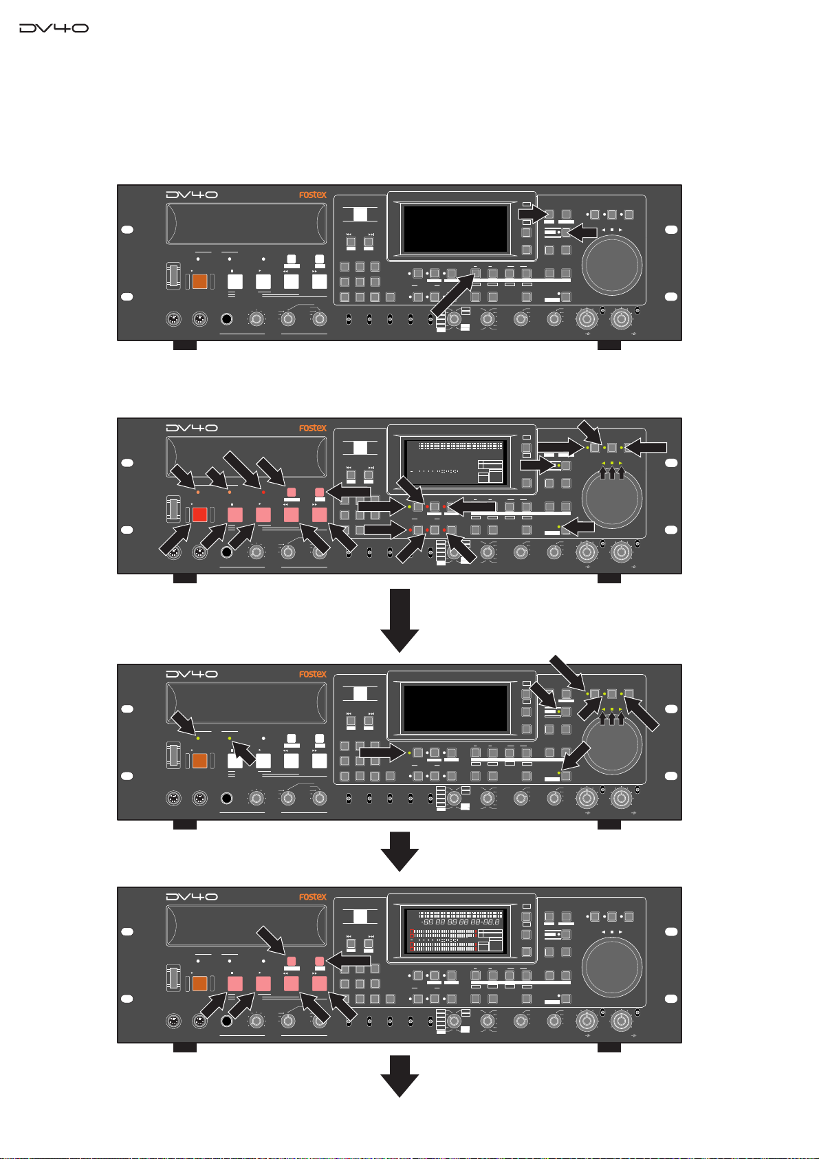
4-7. Display / Key / SW Test
This mode tests if all the FL display segments, LEDs, keys and switches on the DV40 front panel are correctly working.
4-7-1. FL Display and LED Test
Press the [SHIFT], [SETUP] and [SOURCE IN] key.
POWER
KEYBOARD
If DV40 works correctly, every time [SHUTTLE] key is pressed, keys and LEDs will be lit in the following manner.
< Key & LED lit pattern >
D
VD
POWER
D
R
O
EC
R
KEYBOARD
DRIVE
MOUSE
H
D
DRIVE
P
TO
S
MOUSE
DVD MASTER RECORDER
TAPE MODE
HDDVD
PLAY
STOPRECORD
SOURCE PLAY
LOCATE ABS 0
LOCATE REC END
TR1,3+2,4
TR3+4
TR1+2
MAXMIN
PHONES
DVD MASTER RECORDER
TA
P
C
E M
H
A
O
S
D
E
E
TAPE MODE
HDDVD
PLAY
STOPRECORD
SOURCE PLAY
LOCATE ABS 0
LOCATE REC END
LAY
TR1,3+2,4
P
TR3+4
TR1+2
MAXMIN
PHONES
TC SETUP
TC SETUP
REWIND
REWIND
OPEN/CLOSE
SKIP/CURSOR
-
space
1
GHI JKL MNO
4
PQRS TUV WXYZ
REMOTE
LOCAL
CONTROL
OPEN/CLOSE
SKIP/CURSOR
-
space
LIST PLAY
1
GHI JKL MNO
4
PQRS TUV WXYZ
F FW
D
REMOTE
LOCAL
CONTROL
+
ABC3DEF
2
65
89
BWF
SDII
AUDIO FILE
+
ABC3DEF
2
INPUT MON
65
NEW FILE
89
BWF
SDII
AUDIO FILE
ANALOG
ANALOG
U
176.4
O
96
S
88.2
48
44.1
48
176.4
96
88.2
48
44.1
48
TONE REC
TC RDY
C
R
TONE REC
TC RDY
R
/T
IN
E
8
12
6543210OL
TC
SOURCE OUT
INSLATE TONEMUTE
TR1
1
AUDIO EDIT UNDO
30
192
24BIT
(kHz)
16BIT
44.1
RSVD
FRAME RATE
BIT
FS
kHz
-0.1%
FORMAT
SDII
SOURCE OUT
INSLATE TONEMUTE
SLATE TONE
TR1
AUDIO EDIT UNDO
30
192
24BIT
R
(kHz)
D
Y
16BIT
44.1
RSVD
FRAME RATE
INPUT MON
MUTE REC
AUDIO RDY
NEW FILE
STEREO
MULTI(4TR)
TR MODE
STEREO
MULTI(4TR)
TR MODE
MONO
M
U
MONO
IN
INSERT
+0.1%
NORM
-0.1%
PULL
UP/DOWN SAMPLING FREQ
1
2
50
42 34 28 2018
60
∞
TE
INPUT MON
MUTE REC
AUDIO RDY
INSERT
NEW FILE
T
+0.1%
NORM
ER
S
-0.1%
PULL
UP/DOWN SAMPLING FREQ
symbol
07
DIGITAL
INPUT
symbol
07
DIGITAL
INPUT
LIST PLAYCHASE
EDIT
F FWD
MONO
TR4
TR3
TR2
TR1
LIST PLAYCHASE
EDIT
F FWD
R
MONO
EW
TR4
TR3
IN
D
TR2
TR1
DISP
SETUP
FILE SEL
TIME
SETUP
DIRECTORY
UTILITY
DISP
LEVEL
SHIFT
MARGIN
RESET
IN DSTOUT
PREVIEW
TR3
TR2
TR4
LOCATE
24H RUN
30DF
REC RUN
29.97
FREE RUN
29.97DF
EXT RUN
25
24
23.97
TC GEN MODE
SHIFT
ENTER/YESEXIT/NO
MEMORYCUE POINT
STORE
HOLD
INT
WORD
VIDEO
DIGITAL
MIN
TR1 INPUT LEVELTR2 TR4TR3CLOCK
JO
DISP
FILE SEL
SETUP
TIME
VARI PITCH
DIRECTORY
UTILITY
DISP
LEVEL
16
44.1
CLOCK
-INT-
TR2
30DF
29.97
29.97DF
25
24
23.97
IN DSTOUT
TR3
MARGIN
PREVIEW
LOCATE
TC GEN MODE
SHIFT
RESET
SHIFT
ENTER/YESEXIT/NO
MEMORYCUE POINT
TR4
STORE
HOLD
HOLD
24H RUN
INT
REC RUN
WORD
FREE RUN
VIDEO
EXT RUN
DIGITAL
MIN
TR1 INPUT LEVELTR2 TR4TR3CLOCK
SHUTTLEJOGVARI PITCH
ON
ON
OFF
OFF
BY-
BY-
PASS
PASS
MINMAX MAX
G
SHUTTLEJOGVARI PITCH
SHUTTLE
ON
ON
OFF
OFF
BY-
BY-
PASS
PASS
MINMAX MAX
RECORD key, TAPE MODE / MUTE / SLATE TONE / NEW FILE /
INSERT / TC RDY LEDs are lit in RED.
DVD / HD LEDs and CHASE / LIST PLAY / STOP / PLAY / REWIND /
F FWD keys are lit in ORANGE.
INPUT MON / SHIFT / STORE / VARI PITCH / JOG / SHUTTLE LEDs
and LEDs above the jog/shuttle dial are lit in GREEN.
All the segments on the FL display are lit.
DVD MASTER RECORDER
D
V
D
POWER
KEYBOARD
DVD, HD, INPUT MON, STORE, SHIFT, VARI PITCH, JOG, SHUTTLE
LEDs and LEDs above JOG dial are lit in GREEN.
DRIVE
MOUSE
HDDVD
STOPRECORD
H
SOURCE PLAY
LOCATE ABS 0
LOCATE REC END
TAPE MODE
TC SETUP
PLAY
MAXMIN
TR1,3+2,4
PHONES
REWIND
TR4
TR3
TR3+4
TR2
TR1+2
TR1
D
DVD MASTER RECORDER
CHASE
POWER
KEYBOARD
DRIVE
STOP
MOUSE
HDDVD
STOPRECORD
PLAY
SOURCE PLAY
LOCATE ABS 0
LOCATE REC END
TAPE MODE
PLAY
MAXMIN
TR1,3+2,4
PHONES
TC SETUP
REWIND
TR4
TR3
TR3+4
TR2
TR1+2
TR1
LIST PLAYCHASE
EDIT
F FWD
MONO
LIST PLAYCHASE
EDIT
F FWD
REWIND
MONO
OPEN/CLOSE
SKIP/CURSOR
-
space
1
GHI JKL MNO
4
PQRS TUV WXYZ
REMOTE
LOCAL
CONTROL
OPEN/CLOSE
SKIP/CURSOR
-
space
LIST PLAY
1
GHI JKL MNO
4
PQRS TUV WXYZ
F FWD
REMOTE
LOCAL
CONTROL
2
89
AUDIO FILE
2
89
AUDIO FILE
+
ABC3DEF
INPUT MON
65
BWF
SDII
+
ABC3DEF
65
BWF
SDII
ANALOG
ANALOG
Press the [SHUTTLE] key.
V
A
R
I P
IT
C
S
H
24H RUN
REC RUN
FREE RUN
EXT RUN
H
FILE SEL
SETUP
IF
T
DIRECTORY
UTILITY
SHIFT
ENTER/YESEXIT/NO
MEMORYCUE POINT
O
T
S
STORE
HOLD
INT
WORD
VIDEO
DIGITAL
MIN
TR1 INPUT LEVELTR2 TR4TR3CLOCK
SHUTTLEJOGVARI PITCH
BY-
PASS
ON
OFF
MINMAX MAX
S
H
U
T
T
L
E
ON
OFF
BY-
PASS
G
JO
E
R
DISP
TIME
DISP
LEVEL
MARGIN
RESET
IN DSTOUT
INSERT
176.4
96
88.2
48
44.1
48
TONE REC
TC RDY
INSLATE TONEMUTE
SOURCE OUT
TR2
TR1
AUDIO EDIT UNDO
30
192
24BIT
(kHz)
16BIT
44.1
RSVD
FRAME RATE
PREVIEW
TR3
TR4
LOCATE
30DF
29.97
29.97DF
25
24
23.97
TC GEN MODE
INPUT MON
MUTE REC
AUDIO RDY
NEW FILE
symbol
07
MONO
+0.1%
STEREO
MULTI(4TR)
TR MODE
NORM
-0.1%
PULL
UP/DOWN SAMPLING FREQ
DIGITAL
INPUT
Press the [SHUTTLE] key.
DISP
FILE SEL
SETUP
INLTC
DATE
REMAIN
LOCATE
HYMMSDFHSF
ABSCUE
CHASE OFFSETUBGENMEMORY
CHASERDYTCDIGITAL
TONE REC
TC RDY
96
88.2
48
44.1
48
12
8
6543210OL
192
24BIT
(kHz)
16BIT
44.1
AUDIO EDIT UNDO
BIT
FS
kHz
-0.1%
FORMAT
BWF
DVD
SDII
SOURCE OUT
INSLATE TONEMUTE
TR1
30
RSVD
FRAME RATE
1
2
50
42 34 28 2018
60
∞
3
4
INPUT MON
MUTE REC
AUDIO RDY
NEW FILE
STEREO
MULTI(4TR)
TR MODE
MONO
INSERT
176.4
+0.1%
NORM
-0.1%
PULL
UP/DOWN SAMPLING FREQ
symbol
07
DIGITAL
INPUT
M
44.1 88.2 176.4
CD
TIME
S
%
dB
LEVELMARGINNEXTMBPGM
DSD96324824322016
192
CLOCK
-INT-
-EXTWORD
VIDEO
DIGITAL
IN DSTOUT
PREVIEW
TR3
TR2
30DF
29.97
29.97DF
25
24
23.97
TC GEN MODE
LEVEL
MARGIN
RESET
LOCATE
DIRECTORY
UTILITY
DISP
SHIFT
ENTER/YESEXIT/NO
MEMORYCUE POINT
TR4
STORE
HOLD
24H RUN
INT
WORD
REC RUN
VIDEO
FREE RUN
EXT RUN
DIGITAL
MIN
TR1 INPUT LEVELTR2 TR4TR3CLOCK
SETUP
BY-
PASS
ON
OFF
MINMAX MAX
SHUTTLEJOGVARI PITCH
ON
OFF
BY-
PASS
20
CHASE, LIST PLAY, STOP, PLAY, REWIND and F FWD keys are lit
in ORANGE.
All the segments on the FL display are lit.
Press the [SHUTTLE] key.
Page 21
Service Manual
DVD MASTER RECORDER
DVD
HDDVD
STOPRECORD
HD
SOURCE PLAY
LOCATE ABS 0
LOCATE REC END
TAPE MODE
PLAY
TR1,3+2,4
TR3+4
TR1+2
MAXMIN
PHONES
POWER
DRIVE
RECORD
MOUSE
KEYBOARD
[RECORD] key, DVD, HD, TAPE MODE, MUTE, SLATE TONE, NEW
FILE, INSERT, and TC RDY LEDs are lit in RED.
DVD MASTER RECORDER
HDDVD
STOPRECORD
SOURCE PLAY
LOCATE ABS 0
LOCATE REC END
TAPE MODE
PLAY
TR1,3+2,4
TR3+4
TR1+2
MAXMIN
PHONES
POWER
KEYBOARD
No LED is lit.
All the segments on the FL display are lit.
DRIVE
MOUSE
TAPE MODE
TC SETUP
REWIND
TC SETUP
REWIND
LIST PLAYCHASE
space
EDIT
1
F FWD
GHI JKL MNO
4
PQRS TUV WXYZ
MONO
TR4
TR3
TR2
REMOTE
TR1
LOCAL
CONTROL
LIST PLAYCHASE
space
EDIT
1
F FWD
GHI JKL MNO
4
PQRS TUV WXYZ
MONO
TR4
TR3
TR2
REMOTE
TR1
LOCAL
CONTROL
OPEN/CLOSE
SKIP/CURSOR
-
ABC3DEF
2
89
BWF
SDII
AUDIO FILE
OPEN/CLOSE
SKIP/CURSOR
-
ABC3DEF
2
89
BWF
SDII
AUDIO FILE
+
65
NEW FILE
ANALOG
DIGITAL
INPUT
+
65
ANALOG
DIGITAL
INPUT
symbol
07
symbol
07
STEREO
MULTI(4TR)
TR MODE
STEREO
MULTI(4TR)
TR MODE
MUTE
MONO
INSERT
MONO
INPUT MON
TONE REC
MUTE REC
AUDIO RDY
TC RDY
INSERT
NEW FILE
176.4
96
+0.1%
88.2
NORM
48
-0.1%
44.1
48
PULL
UP/DOWN SAMPLING FREQ
Press the [SHUTTLE] key.
SETUP
INLTC
DATE
REMAIN
LOCATE
HYMMSDFHSF
ABSCUE
CHASE OFFSETUBGENMEMORY
1
2
∞
3
4
INPUT MON
NEW FILE
50
12
42 34 28 2018
60
TONE REC
MUTE REC
AUDIO RDY
TC RDY
INSERT
176.4
96
+0.1%
88.2
NORM
48
-0.1%
44.1
48
PULL
UP/DOWN SAMPLING FREQ
8
Press the [SHUTTLE] key.
SLATE TONE
SOURCE OUT
INSLATE TONEMUTE
TR1
AUDIO EDIT UNDO
30
192
TC RDY
24BIT
(kHz)
16BIT
44.1
RSVD
FRAME RATE
M
CHASERDYTCDIGITAL
BIT
FS
kHz
44.1 88.2 176.4
-0.1%
6543210OL
FORMAT
BWF
DVD
CD
SDII
INSLATE TONEMUTE
SOURCE OUT
TR1
AUDIO EDIT UNDO
30
192
24BIT
(kHz)
16BIT
44.1
RSVD
FRAME RATE
DISP
SETUP
FILE SEL
TIME
DIRECTORY
UTILITY
DISP
LEVEL
SHIFT
MARGIN
ENTER/YESEXIT/NO
RESET
LOCATE
TIME
LEVEL
MARGIN
RESET
LOCATE
MEMORYCUE POINT
TR4
STORE
HOLD
24H RUN
INT
REC RUN
WORD
FREE RUN
VIDEO
EXT RUN
DIGITAL
MIN
TR1 INPUT LEVELTR2 TR4TR3CLOCK
DISP
FILE SEL
SETUP
DIRECTORY
UTILITY
DISP
SHIFT
ENTER/YESEXIT/NO
MEMORYCUE POINT
TR4
STORE
HOLD
24H RUN
INT
WORD
REC RUN
VIDEO
FREE RUN
DIGITAL
EXT RUN
MIN
TR1 INPUT LEVELTR2 TR4TR3CLOCK
IN DSTOUT
PREVIEW
TR3
TR2
30DF
29.97
29.97DF
25
24
23.97
TC GEN MODE
S
%
dB
LEVELMARGINNEXTMBPGM
DSD96324824322016
192
CLOCK
-INT-
-EXTWORD
VIDEO
DIGITAL
IN DSTOUT
PREVIEW
TR3
TR2
30DF
29.97
29.97DF
25
24
23.97
TC GEN MODE
BY-
PASS
BY-
PASS
ON
OFF
MINMAX MAX
ON
OFF
MINMAX MAX
SHUTTLEJOGVARI PITCH
ON
OFF
BY-
PASS
SHUTTLEJOGVARI PITCH
ON
OFF
BY-
PASS
Back to the Key & LED lit in GREEN pattern.
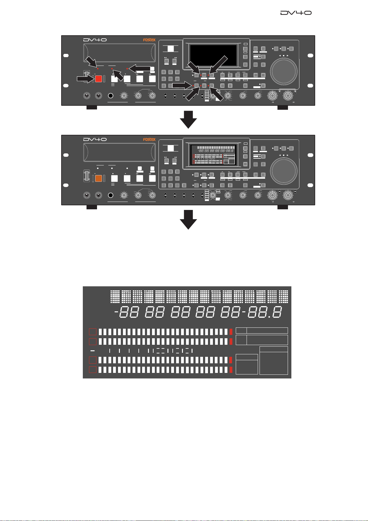
< FL display >
Every time the [SHUTTLE] key is pressed, all the segments on the FL display will be on and off alternatively. Check
f all the segments are correctly lit.
SETUP
INLTC
DATE
REMAIN
LOCATE
1
2
∞
3
4
ABSCUE
UB
GENMEMORY
50
60
42 34 28 2018
YM
H
CHASE OFFSET
MSDF
CHASERDYTCDIGITAL
8
12
6543210OL
H
SF
M
S
%
dB
LEVELMARGINNEXTMBPGM
BIT
FS
kHz
44.1 88.2 176.4
-0.1%
FORMAT
BWF
DVD
CD
SDII
24322016
48
32
96
CLOCK
-INT-
-EXTWORD
VIDEO
DIGITAL
DSD
192
In order to get back to the normal display mode, press the [EXIT/NO] key while holding down the [SHIFT] key in the
condition that all the segments on the FL display are lit.
21
Page 22
Service Manual
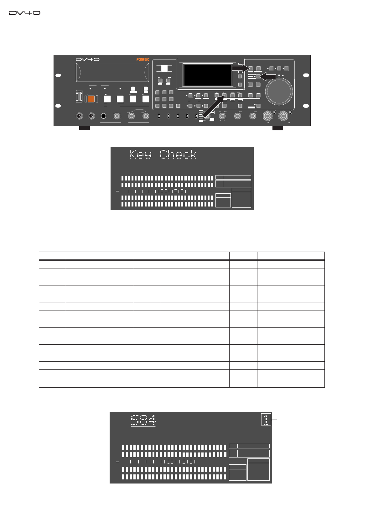
4-7-2. Key Function Test
Press the [SHIFT], [SETUP] and [SOURCE OUT] key.
POWER
KEYBOARD
If DV40 is put into the Key Function Test mode, “Key Check” will appear on the FL display.
DRIVE
MOUSE
DVD MASTER RECORDER
TAPE MODE
HDDVD
PLAY
STOPRECORD
SOURCE PLAY
LOCATE ABS 0
LOCATE REC END
TR1,3+2,4
TR3+4
TR1+2
MAXMIN
PHONES
1
2
∞
3
4
TC SETUP
REWIND
50
42 34 28 2018
60
OPEN/CLOSE
SKIP/CURSOR
-
space
1
2
GHI JKL MNO
4
PQRS TUV WXYZ
89
REMOTE
LOCAL
CONTROL
AUDIO FILE
+
ABC3DEF
65
BWF
SDII
ANALOG
symbol
07
DIGITAL
INPUT
12
INPUT MON
AUDIO RDY
NEW FILE
MONO
+0.1%
STEREO
NORM
MULTI(4TR)
-0.1%
PULL
UP/DOWN SAMPLING FREQ
TR MODE
8
6543210OL
MUTE REC
INSERT
176.4
96
88.2
48
44.1
48
INSLATE TONEMUTE
TONE REC
TR1
TC RDY
AUDIO EDIT UNDO
192
24BIT
SOURCE OUT/TR1
(kHz)
16BIT
44.1
RSVD
SOURCE OUT
30
FRAME RATE
BIT
FS
kHz
FORMAT
BWF
LIST PLAYCHASE
EDIT
F FWD
MONO
TR4
TR3
TR2
TR1
DISP
SETUP
SETUP
IN DSTOUT
PREVIEW
TR3
TR2
30DF
29.97
29.97DF
25
24
23.97
TC GEN MODE
24
48
DISP
LEVEL
MARGIN
RESET
TR4
LOCATE
CLOCK
-INT-
24H RUN
REC RUN
FREE RUN
EXT RUN
DIRECTORY
UTILITY
SHIFT
ENTER/YESEXIT/NO
MEMORYCUE POINT
STORE
HOLD
INT
WORD
VIDEO
DIGITAL
MIN
TR1 INPUT LEVELTR2 TR4TR3CLOCK
FILE SEL
TIME
SHIFT
BYPASS
ON
OFF
MINMAX MAX
SHUTTLEJOGVARI PITCH
ON
OFF
BY-
PASS
In this condition, if a key on the DV40 front panel is pressed, the corresponding reference number will be displayed on
the FL display. Up to 5 reference numbers can be displayed when multiple keys are pressed at a time. The number of
keys pressed at a time is also displayed at the far right of the FL display. The table below indicates the relationship
between the key and the corresponding reference number.
Ref. No. Key Name
S13 VARI PITCH
S14 FILE SEL
S15 SETUP
S17 SHUTTLE
S18 JOG
S19 SETUP
S21 MEMORY
S22 ENTER/YES
S23 EXIT/NO
S25 AUDIO EDIT
S26 UNDO
S27 LOCATE
S28 STORE
S29 SOURCE OUT
S30 DEST IN
Ref. No. Key Name
S31 DEST OUT
S32 CUE POINT
S33 SOURCE IN
S34 SLATE TONE
S35 MUTE
S36 INPUT MON
S37 TC RDY
S38 AUDIO RDY INSERT
S39 AUDIO RDY NEW FILE
S40 symbol / 0
S41 SKIP CURSOR >>|
S42 DEF / 3
S43 MNO / 6
S44 WXYZ / 9
S45 OPEN/CLOSE
Ref. No. Key Nameey Name
S46 ABC / 2
S47 JKL / 5
S48 TUV / 8
S49 SKIP CURSOR |<<
S50 space / 1
S51 GHI / 4
S52 PQRS / 7
S80 STOP
S81 PLAY
S82 REWIND
S83 F FWD
S84 RECORD
S85 CHASE
S86 LIST PLAY
22
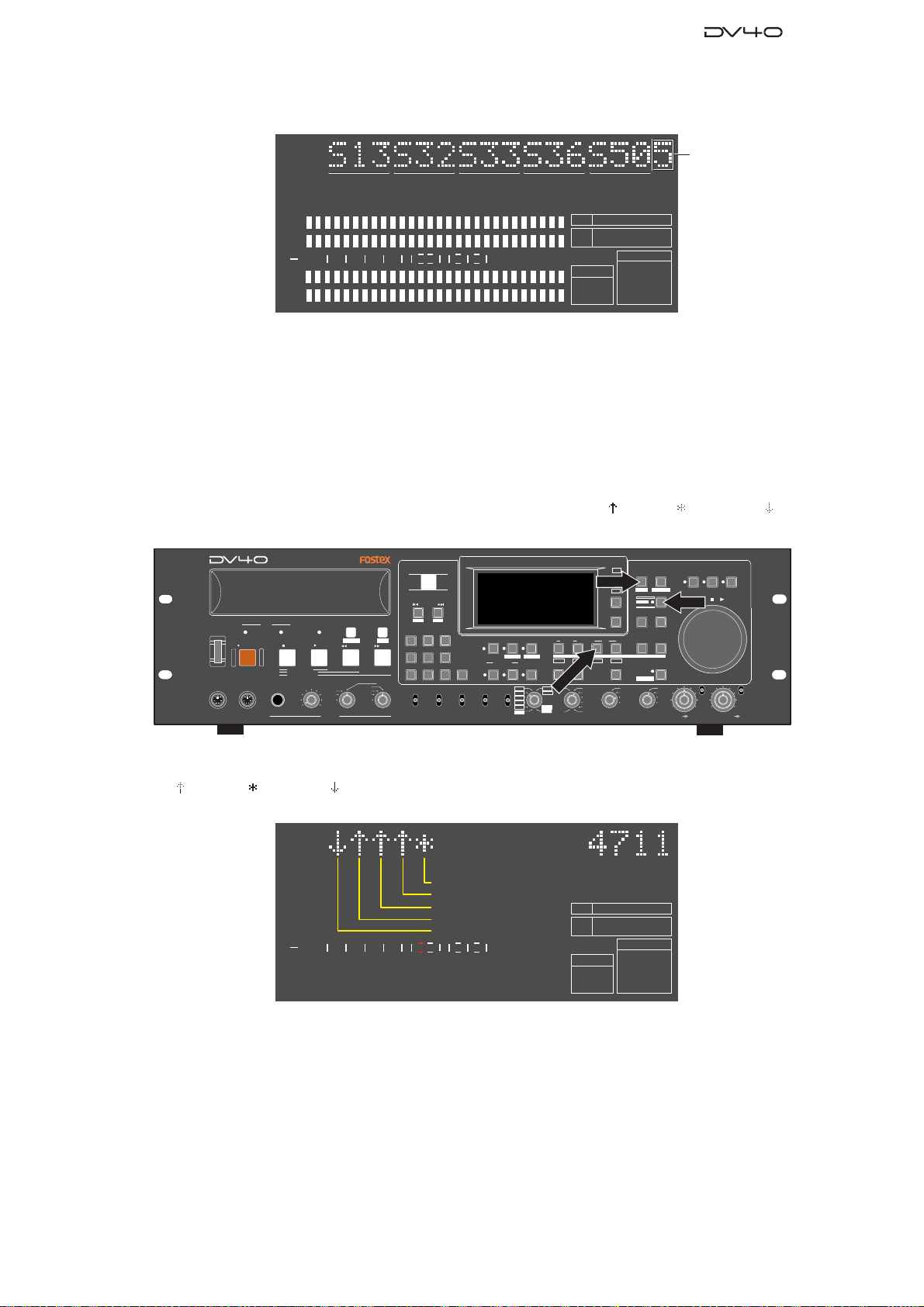
• Example when [RECORD] key is pressed.
[RECORD]
1
2
50
42 34 28 2018
60
∞
3
4
12
8
6543210OL
BIT
FS
kHz
FORMAT
BWF
48
24
CLOCK
-INT-
The number of key
pressed at a time.
Page 23
Service Manual
• Example when [SPACE] / [INPUT MON] / [SOURCE IN] / [CUE POINT] / [VARI PITCH] key are pressed at a
time.
The number of key
[SPACE] [INPUT MON] [CUE POINT] [VARI PITCH][SOURCE IN]
pressed at a time.
1
2
50
42 34 28 2018
60
∞
12
8
6543210OL
3
BIT
FS
kHz
FORMAT
BWF
48
24
CLOCK
-INT-
4
In order to get back to the normal display mode, press the [EXIT/NO] key while holding down the [SHIFT] key in the
condition that “Key Check” is displayed on the FL display.
4-7-3. Toggle SW Function Test
There are five toggle switches placed on the lower section of DV40 front panel. This mode checks if they are correctly
working or not by displaying the corresponding toggle switch position among up ( ), center ( ) and down ( ). In order
to enter this test mode, press the [SHIFT], [SETUP] and [DEST IN] key.
POWER
KEYBOARD
DRIVE
MOUSE
DVD MASTER RECORDER
TAPE MODE
HDDVD
PLAY
STOPRECORD
SOURCE PLAY
LOCATE ABS 0
LOCATE REC END
TR1,3+2,4
TR3+4
TR1+2
MAXMIN
PHONES
TC SETUP
REWIND
TR4
TR3
TR2
TR1
OPEN/CLOSE
SKIP/CURSOR
-
space
1
2
GHI JKL MNO
4
PQRS TUV WXYZ
89
REMOTE
LOCAL
CONTROL
AUDIO FILE
ABC3DEF
BWF
SDII
+
SOURCE OUT
INPUT MON
STEREO
MULTI(4TR)
TR MODE
MONO
MUTE REC
AUDIO RDY
INSERT
NEW FILE
+0.1%
NORM
-0.1%
PULL
UP/DOWN SAMPLING FREQ
65
symbol
07
ANALOG
DIGITAL
INPUT
INSLATE TONEMUTE
TONE REC
TR1
TC RDY
AUDIO EDIT UNDO
T
S
E
176.4
30
192
D
96
24BIT
88.2
(kHz)
48
44.1
16BIT
44.1
RSVD
48
FRAME RATE
LIST PLAYCHASE
EDIT
F FWD
MONO
DISP
FILE SEL
SETUP
TIME
SETUP
IN DSTOUT
PREVIEW
TR3
TR2
1
R
/T
IN
30DF
29.97
29.97DF
25
24
23.97
TC GEN MODE
LEVEL
MARGIN
RESET
LOCATE
DIRECTORY
UTILITY
DISP
SHIFT
ENTER/YESEXIT/NO
MEMORYCUE POINT
TR4
STORE
HOLD
24H RUN
INT
REC RUN
WORD
FREE RUN
VIDEO
DIGITAL
EXT RUN
MIN
TR1 INPUT LEVELTR2 TR4TR3CLOCK
SHIFT
BY-
PASS
ON
OFF
MINMAX MAX
SHUTTLEJOGVARI PITCH
ON
OFF
BY-
PASS
Then, up ( ), center ( ) or down ( ) characters indicating the position of corresponding switches appear on the FL
display as shown below.
PULL UP/DOWN SW: NORM (center)
TR MODE SW: MONO (up)
1
50
42 34 28 2018
60
∞
INPUT SW: ANALOG (up)
AUDIO FILE SW: BWF (up)
CONTROL SW: LOCAL (down)
8
12
6543210OL
BIT
FS
kHz
FORMAT
BWF
48
24
CLOCK
-INT-
In order to get back to the normal display mode, press the [EXIT/NO] key while holding down the [SHIFT] key.
23
Page 24

Service Manual
5. EXPLODED VIEW, PCB ASSEMBLY AND PARTS LIST
DV40 OVERALL EXPLODED VIEW 1 & PARTS LIST
Ref. No. Part No. Description
1 8212 7000 00 Panel, control, DV40
2 8212 3860 00 Lens, LED, triangle
3 8212 3850 00 Lens, LED, square
4 8212 3780 00 Bearing, jog
5 8223 3050 00 Shaft, jog, DV40
6 8221 3740 00 Bracket, jog, DV40
7 8223 3060 00 Disc, jog, DV40
8 8274 3290 00 PCB assy, JOG, DV40
9 8226 1842 10 Button, 6 x 6 x 20.3, N3
10 8226 1842 11 Button, 6 x 6 x 20.3, BLK
11 8226 1831 09 Button, 11 x 11 x 15.3, N6
12 8274 3260 00 PCB assy, DISPLAY, DV40
13 8221 3650 00 Panel, dress, DV40
14 8226 2680 00 Escutcheon, button
15 8212 2682 00 Lens, LED
16 8212 3840 01 Protector, REC, N2
17 8204 0370 01 Ring, CSTW-2
18 8204 2250 81 WS, REY-RING, E-05, ZMB
19 8204 2330 01 WS, PL, BLK, 3 x 8 x 2
20 8221 3690 00 Bracket, front, DV40
21 8216 7660 00 Sheet, door, DV40
22 8274 3410 00 PCB assy, PS/2, DV40
23 8212 7010 00 Door, DV40
24 8214 4020 00 Spring, door, DV40
25 8221 3710 00 Bracket, door, DV40
26 8274 3270 00 PCB assy, CTRL KEY, DV40
27 8226 1721 01 Knob, volume, BLK
28 8216 4461 01 Cover, volume, BLK
29 8226 0130 02 Button, push, B, BLK
30 8226 2690 00 Knob, dual
31 8216 4470 01 Cover, jog, BLK
32 8223 3070 00 Knob, jog, DV40
33 8221 1730 00 Angle, back, 133
34 8221 2142 00 Panel, top, D-160 / DV40
35 8216 7720 00 Tape, window, DV40
36 8212 7020 00 Window, FL, DV40
37 8204 2380 00 PSW, 6.2 x 9.5 x 0.25
24
Page 25
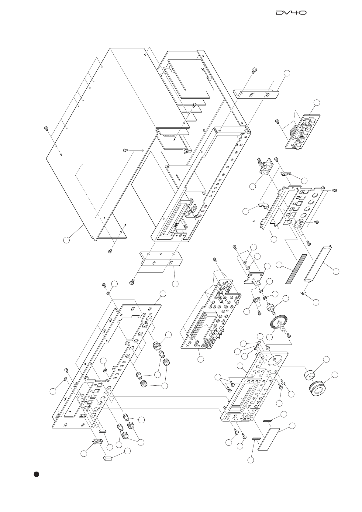
Service Manual
A
B
C
D
D
1
2
2
3
4
4
5
37
37
6
7
8
10
9
9
11
9
12
13
14
15
16
17
18
19
20
21
23
24
22
25
25
26
28
27
28
27
27
29
30
34
33
33
31
32
36
35
35
BBT3 X 6BZn
BBT3 X 6BZn
F3 X 6CZn
B3 X 6BZn
BBT4 X 8BZn
BBT4 X 8BZn
BBT3 X 8BZn
BBT3 X 6BZn
BBT3 X 6BZn
BBT3 X 8BZn
BBT3 X 6BZn
BBT2 X 3BZn
P2 X 3CZn
BBT3 X 8BZn
BBT3 X 8BZn
BPT2 X 4CZn
BBT2.6 X 6CZn
DV40 OVERALL EXPLODED VIEW 1
25
Page 26

Service Manual
DV40 OVERALL EXPLODED VIEW 2 & PARTS LIST
Ref. No. Part No. Description
1 8221 3660 00 Panel, rear, L, DV40
2 8274 3320 00 PCB assy, AD, DV40
3 8274 3330 00 PCB assy, DA, DV40
4 8216 7680 00 Shield, XLR, A, DV40
5 8221 3670 00 Panel, rear, C, DV40
6 8274 3350 00 PCB assy, TC CARD, DV40
7 8274 3370 00 PCB assy, ETHER CARD, DV40
8 8216 7691 00 Shield, XLR, B, DV40
9 8221 3760 00 Panel, blank, DV40
10 8221 3681 00 Panel, rear, R, DV40
11 8274 3340 00 PCB assy, AES/EBU, DV40
12 8274 3360 00 PCB assy, VIDEO SYNC IN, DV40
13 8274 3250 00 PCB assy, WORD I/O, DV40
14 8274 3280 00 PCB assy, TOGGLE, DV40
15 8221 3730 00 Bracket, toggle, DV40
16 8216 6920 00 Sheet, volume, DP-8 / DV40
17 8221 3721 00 Chassis, DV40
18 8207 0130 00 Foot, FF1011
19 8274 3300 00 PCB assy, INPUT VOL, DV40
20 8221 3750 00 Spacer, INPUT VOL, DV40
21 8274 3310 00 PCB assy, PHONES, DV40
22 8207 0117 01 Holder, cord, CS-1
23 8274 3230 00 PCB assy, CPU MODULE, DV40
24 8277 5350 15 Cable assy, FC, 40P, /F-/F,
25 8274 3240 00 PCB assy, MAIN, DV40
26 8274 3380 00 PCB assy, POWER, DV40
27 8216 7701 00 Cover, isolation, power, DV40
28 8218 2630 00 Sticker, GND
29 8274 3390 00 PCB assy, REGULATOR, DV40
30 8221 2610 00 Bracket, AC-IN, FD-8 / DV40
31 8274 3400 00 PCB assy, SW POWER, DV40
32 N/A
33 8270 8900 00 DVD-RAM drive, LF-D211N
34 8221 3701 00 Bracket, drive, DV40
35 8249 0480 00 Motor, fan, DC12V, 60 x 60 x 25.6,
36 8276 8010 00 Cord, power, UL/CSA, VM0033-0089
8276 8021 00 Cord, power, CEE, 0309B-0310B
8276 9170 00 Cord, power, BS, 3C, KP610-KS31A
8276 8000 00 Cord, power, DM, VM1292-1298
37 8221 3360 00 Spacer, PCB, DV40
38 8239 1200 00 Battery, 3V, CR2032 (Included in the
106MHz, L150
FBA06A12L4E
part # 25)
26
Page 27
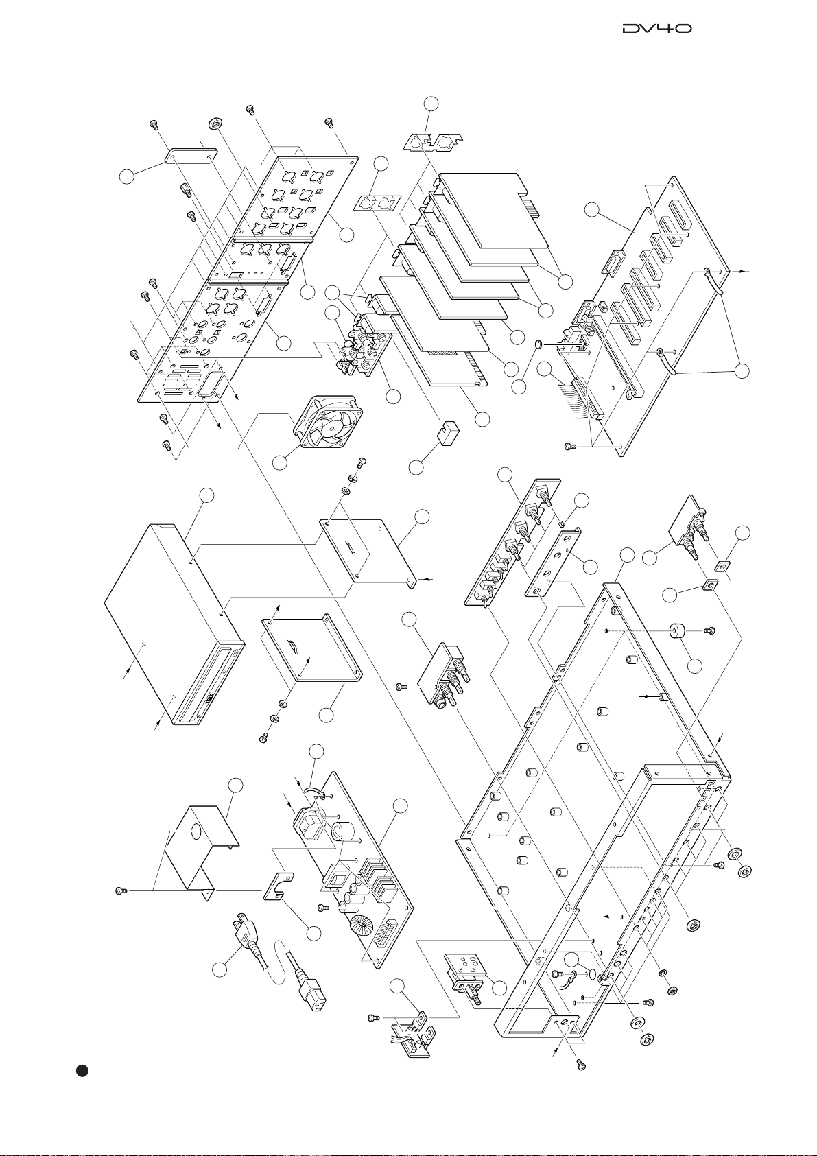
Service Manual
G
A
G’
G
G’
E’
E
E’
E
C
B
F
F
H
H
20
20
19
18
BBT3 X 6BZn
17
16
15
14
B3 X 6BZn
1
2
3
4
5
6
7
8
9
10
12
13
23
34
34
33
24
35
22
22
26
21
25
36
27
29
31
30
28
BBT3 X 6BZn
B3 X 8BZn
BBT3 X 8BZn
BBT3 X 6BZn
B3 X 6BZn
B3 X 6BZn
BBT3 X 8BZn
BBT3 X 6BZn
BBT3 X 6BZn
BBT3 X 6BZn
Nut 11, Ø8.3
W Ø8.3
BBT3 X 6BZn
Nut 11, Ø8.3
Nut 8
BBT3 X 6BZn
Nut 11, Ø8.3
W Ø8.3
B3 X 6BZn
SEMS
4 X 6
Included in the part # 33
Included in the part # 33
Included in the
D-SUB connector
B3 X 6BZn
37
38
11
B3 X 6BZn
B3 X 6BZn
DV40 OVERALL EXPLODED VIEW 2
27
Page 28
Service Manual
8252505301
POWER
DISPLAY
TC/WORD
POWER
AD1
AD2
DA2
DA1
TC
VGA
ETHER
JTAG-FPGA
JOG
/PROGRAM
TMS
TDI
DGND
D+3.3
CCLK
DATA
TDO
TCK
DVD
HDD
CPU
PCB,MAIN,DV40
FAN MOTOR
POWER
DVD
ADDA
(W305)
(W301)
PHONES
AES/EBU TR1,2
AES/EBU TR3,4
TC
CHK
SELF
DGND
PS/2
R23
R24
R25
R26
R27
R46
R47
R48
R49
R50
R51
R52
R53
R54
R55
R56
R28
R29R30
R31
R32
R33
R34
R35
R36
R37
R38
R39
R40
R41
R42
R43
R44
R45
J17
50
49
2
1
C10
C11
J1571
J21
C310
L7
L9
L10
U41
U42
U43 U44
R143
R144
R145
R146
U303
13
J301
B1
C95
C96
L11
L12
R121
R122
R123
R125
R126
U45
U46
U47 U48
+
C12
+
C13
C14
C97 C98
D1D2
61
J12
L1
+
C309
L13 L14
R9
R127 R128
U10
L8
15
1
39
40
2
1
R57
R58
14
J2
J18
4
4
J1
1
W302
1
W303
W304
112
+
C301
C26
C34
C302
C306
15
J302
14
W301
U16
13
U17 13
11
U21 U23
U302
14
J303
C32
+
C303
C27
+
C304
C307
C308
17
D15
D16
R16
R17
R18
R19
R20
R21
R301
R302
1
U301
L301
60
145
70
155
8084
165
168
C25
1
1
C17
C21
113U14
1
11
U191U20
C24
J16
C20
113U15
C22
C30C31
105
2030
115
40
125
50
135
C19
8
1
11
U13
E4
C8
C28
C33
R13
R22
1
8
U9
1
1
8
U22
1
9
E5
R8
18U2
1
8
U3
1
8U58
1
U719U11
11
C123
10 20 30 40
J3
1
11
U18
C1C2
C3
C5
C6 C15C16C29
1
8
U1
8
U6
L111
U52
8
R124
85
210
95
+
C111
+
C112
C4
U4
1
R14
R15
60
C18C23
R6
R711U12
C124
1
R154
R157
C109
C110
61
J13
J14
J25
L21
L22
L25
R135
R140
R142
+
C113
R148
R155
R156
L26
L27
L28
55
60
55
R59
C105
C106
R137
U50
1
R147
R149
+
C103
C104
C107
C108
D3
D4D5
D7
D8
D9D10
D11D12
D13
D14
L23
L24
R133R134
R136
R138
R139
R141
U49
1
9
L302
U304
C311
+C312
L303
D6
60
55
R60
45352515
10 20 30 40 50
45352515
J4
+
9
10 20 30 40 50
45352515
J5
C36 C37
C38 C39
C41
C45
C50
C51
C52
C53
C54
R62 R63
R64R65
R71
R72
R73
R74
L105
L106
L107
L108
1
U24
8
U25
100
80
50
20
10
U26
9
U29
X1
X2
+
C115
+
C116
C35
C43
1
8
U28
+
C9
C40
C42
C49
C55
E1
14
J19
L4
R66
R67
L104
1
U27
+
C46
C48
C44
C47
C72
C73
C74
+
C75
C76
C77
C78
C79
L6
C7
R68
C99
R86
R87
R88
R91
R92
9
1
100
80
60
50
30
20
10
U32
U33
C59
C60
+
C62
C64
C65
C67
C69C70 C71
C80
C81
E2
E3
L5
R75
R76
R77
R78
R79
R83
R84
R93
R94
L109
100
80
60
50
U30
+
C119
+
C120
C61
C63
C66
C68
C121
L110
R80
R81
R82
U31
9
C117
+
C118
C100
R89
R90
9
1
30
20
10
C56C57 C58
C87
C89
C91
C92
C94
19
J20
16
J24
R4
R5
R96
R97
R98
R101
R105
R106
R107
R108
60
80100
72
40
20
1
108
U35
U36 U37 U38 U39
1
11
U40
+
+
C122
R151
R152
R153
C126 C127 C128 C129
R158 R159 R160 R161
C83
C84
C85
C88
C90
C93
R1R2R3
5
+
C82
+
C86
15
J22
C125
1
8
U53
J7
15
102030
14
W305
R112
R113R114
36
U34
J8
15
1020
30
J9
30 1020
15
R10
R115
R116R117
R118
R119R120
1
J6 15
102030
R11
R12R109
R110R111
R150
1
1
1
11
1
28
DV40 PCB ASSEMBLIES
• Parts Side of MAIN PCB
Page 29

Service Manual
• Foil Side of MAIN PCB
29
Page 30

Service Manual
8590
100110120130140150160168
8251712000
MD0
MD1
MD2
MD3
MD4
MD5
L
H
MRST
NMI
IRQOUT
PCB,CPU MODULE,DV40
+
C1
+
C2
+
C3
C6
+
C7
C8
C26
C40
C41
C42
C43
D1
R2
R25
R33
R34
15
U1
U2
U8
U10
1
8
X3
R42
R1
R3
E3
R37
U9
5
U11
1
C4C5
C14
C16
C27
C28
+
+
C30
C31
C32
R7
1
52
104
U3
X1
C13
C17
R4
R18
R19
R20
R21
R22
R23
R24
R26
R27
R28
R29
R30
R31
R32
C9
C10
C11
C12
C19
C20
C21
C33
C34
C35
C36
C39
E2
R40
R41
R5
R6
R8
R10
R11
R12
R13
R14
R15
R16
R17
R35
R36
R38
1
9
U4
X2
+
C44
C46R39
W1
C38
+
C45
C18
C29
C15
C37
U6
C47
C23
C24
1
25
1
U5
1
28
1
28
C22C25
R9
R43
U7
E1
2
50
49
J4
J2
1
2
J3
1
• Parts Side of CPU MODULE PCB
30
Page 31

Service Manual
• Foil Side of CPU MODULE PCB
31
Page 32

Service Manual
• Parts Side of AD PCB
-10dBV -10dBV
J201
TR2
S201
R215
R206
R207
U201
C207
+
C210
1
5
15
J1
29
C212
R205
5
C208
R236
C211
1
+
C209
R235
R210
R208
C203
R211
R203
R204
C201
C202
C215
C213
+
5
R209
R212
C244
C243
C221
+
C214
C236
+
+
C234
R226
+
R229
R228
C239
C220
U202
R230
5
C241
U1
U2
R2
R3
S101
L201
L202
+
R201 R202
+
R233
INPUT VOL
R237
13
C246
+
R234
C216
1
+
R213
C235
C240
+
C242
C219
1
U205
R224
U204
C238
W201
Q201
R227
R225
U203
R223
C217
R217R218
R219R220
+4dBu+4dBu
R115
TRIMTRIM
R221 R222
R232
R231
R214R216
R106
R107
C110
U101
C107
+
J101
TR1
R105
5
C112
L101
L102
C101
R103
R135
C108
R136
C103
R104
1
C111
R108
R111
C136
C115
+
C113
5
C134
U102
+
R129
R130
C139
5
C120
R126
+
R128
C141
+
C109
R110
R109
C114
R112
C121
+
C144
C143
+
+
R101 R102
+
R137
C102
13
R133
C146
+
R134
C116
1
R113
C135
R124
+
+
C140
C142
C119
1
U105
INPUT VOL
W101
U103
U104
Q101
C117
C138
R123
R125
R127
R117R118
R119R120
R121
R122
R132
R131
R114R116
C18
C17
D201D202
+
+
C11
U3
C14
15
+
W1
C19
C1
+
C3
1
U4
L1
C2
C5
C6
C7
C137
+
C4
1
+
+
C8
C9
D101 D102
C10
+
C12
PCB,AD,DV40
8252507201
C13
C237
+
C15
R1
C20
32
Page 33

• Foil Side of AD PCB
Service Manual
33
Page 34

Service Manual
• Parts Side of DA PCB
J252
TR2
UNBAL-10dBV
J251
BAL+4dBu
J152
UNBAL-10dBV
J151
TR1
BAL+4dBu
C51
C52
TRIM TRIM
L252
R290
D251
K251
L251
1
R289
L152
R190
D151
1
K151
R189
L151
L153
R277
L253
+
Q254
+
R75
15
15
J51
R53
29
R287
U52
U53
R291
C277
C271
R51 R52
C282
C281
6
Q154
R66
C68
W53
41
PHONES
41
C280
+
R272 R275
C266
U62
R273R278
C263
R58
U61
U57
D51
W51
U54
R251
U64
+
C61
C58
R265
R285
R284
U252
U251
+
C275
R70
C264
R68
U253
C287
C255
+
R280
R294
R282
+
R257 R258
C253
R255
C262
R270
R292
R261 R262
R253
C251
+
R283
R286
+
+
C260
C259
R259 R260
R263R264
+
C285
C269
R281
C276
C265
R295
C270
+
+
U60
R271
R293
R254
C258
C254
R256
C288
R67
C261
R276
C257
+
R266
Q251
R69
C283
+
C286
C284
R252
C252
C256
+
C56
+
+
+
C59
C69
C70
C66
D52
R55
R177
R191
R187
+
C67
C166
C163
R57
R56
C62+C63
+
15
C180
+
C60
U55
U63
R172R178
R173 R175
W52
U56
+
+
C185
C186
+
C160
C159
R159 R160
+
C182
C152
C177
+
+
R163R164
C171
+
R183
R181
C176
C165
R195
U58
R154
R152
C170
R171
R193
C158
C154
C181
+
R182
R180
R194
C164
C162
+
R170
C187
R192
R157 R158
R161 R162
U59
R59
R60
C153
R151
R153
R155
U153
C155
PCB,DA,DV40
8252507102
C169
C161
C157
R176
6
R185
R184
C175
U152
U151
+
R186
+
C188
R165
R166
Q151
R54
R61
C183
R156
C184
C156
C151
+
34
C57
C64
L51
C65
1
+
+
C54
U51
C53
C71
Page 35

• Foil Side of DA PCB
Service Manual
35
Page 36

Service Manual
8251713100
PCB,ETHER CARD,DV40
C101
C102 C103
C104
C111
C113
C114
C115C116
14
1
2
13
J004
R106
R108
U100
104
X100
R302
C302
R004
R005
R008
R107
1
8
U004
25
1
U303
R014
C010
R006
C009
1
250
49
J300
R300
R301
U300
50 26
C100
R105
52
1
9
C203
C204
C208
C401
C402
C404
C405
C407
C408
C409
C411
C413
C414
D403 D405
C012
L402
L403
L404
R200
R201
R202
R402
R403
R404
R405
R406
R407
R408
R411
R412
R415
U003
72
108
100
80
11
40
20
21
60
61
41
U400
1
X400
C412
R007
R203
R204
R418
C011
C105
C106
C107
C108
C109
C110
C207
C406
D406
R100
R101
R102
R103
R104
R109
R110
R111
R112
R400 R401
R410
R413
R414
1
208
156
C030
C031
C032
C033
C034
R424
R425
C202
R009
R011
R012
R013
C400
1
U201
C410
C415
C418
C419
C420
C421
C422
C423
D400D401
L400
L401
R001
R002
R003
R205
R206
R207
R417
R419
R420
R421
R422
80
U401
J400
C007
+
C008
15
U001
5
C416
C417
120
C005
D402
R010
40
36
20
U200
60
60
+
C001
C002
C003
+
C004
+
C006
C200
C201
C205
C206
C209
L000L001
1
U002
1
140
C300
25
U302
+
C020
C021
C301
13
J005
1
2
C112
• Parts Side of ETHER CARD PCB
36
Page 37

• Foil Side of ETHER CARD PCB
Service Manual
37
Page 38

Service Manual
• Parts Side of TC CARD PCB
L10
C73
R51
C75
R54
R45
R41
C69
C65
J7
PCB,TC CARD,DV40
R43
+
C51
E3
+
C37
C66
1
C61
L13
IN
C67
+
R39
C79
D1 D2D3
L12
E1
8252508201
31
R46R47
+
C35
J8
+
C94
+
C93
L3
L4
4
WORD I/O
J2
1
+
C11
C9
L2
C7
VIDEO IN
1
C92
+
C5
14
W1
C17
8
J5
THRU OUT
U23
R34
111
3351
20
C47
C44
C32
30
C29
C15
R2
+
C10
1
32
C57
R11
R8
R10
R9
R55
L8
C71
U19
+
U15U16
50
C53
U17
C81
C41
8
R31
+
R49
R29
R28
C70
R35
R21 R22
U10 U11
C46
C48
C43
R30
C45
R27
+
+
D4D5
1
C31
U18
R52
R48
5
U20
C91
L7
R42
R38
C50
L5
L6
C52
C38
+
1
R17
L14
C22
C21
L11
R15
C24
R20
C33
C28
R18
C30
R14
U12
9
C39
R23
+
C78
C83
C90
X2
C36
R25
1
C40
1
R16
C23
40
C25
U8U9
E2
50
U13
R12
8
R13
C20
U7
C27
R19
+
C8
C6
L1
C4
J6
OUT
L9
C74
R53
2212
33
C68
C64
R44
R40
C72
+
23
C82
+
C63
1
C62
C80
R50
5
+
U21
+
R36
R37
C60
W4
60
W5
U24
C87
1
+
W3
1
J1
1
13
C86
C12
C1
9
U1
C3
11
C2
2
+
+
C58
C59
C89
+
C88
C55
C77
+
U3
U2
C76
1
+
C14
+
X1
R1
C16
16M ADJ.
+
34
52
U22
64
119
C49
U14
90
C85
C42
C34
U6
90
C84
100
C54
C56
70
L16
20
10
R4
60 70
1
R6
C13
C26
C19
U4
8
L15
R7
C18
1
L17
R3
U5
4114
MAIN
W2
38
Page 39

• Foil Side of TC CARD PCB
Service Manual
39
Page 40

Service Manual
J3
PCB,POWER,D-108
DGND
D+5
DGND
D+12
N.C.
D+5
DGND
AGND
AGND
N.C.
J1
D+5
DGND
DGND
DGND
D+5
DGND
Vdisp
J2
J4
TO FAN
TO DISPLAY
4049
TO REGULATOR
C32
Q2
D10
FOR CONTINUED PROTECTION AGAINST RISK OF FIRE.
CAUTION
REPLACE ONLY WITH SAME TYPE FUSE.
EN VUE DE LA PROTECTION CONTINUELLE CONTRE LES
PRECAUTION
RISQUES D'INCENDIE,REMPLACER AVEC LE MEME TYPE DE FUSIBLE.
T800mA
250V
D14
8251974
501
W2
TO SWITCH
AC
AC
A+15~18
A-15~18
:
:
C5
+
D9
2
14
3
L1
U9
F1
C1
C2
C3
2
1
3
L2
4
L5
L
N
L6
C9
C17
C25
D6
R1
DSC
U5
C10
C11
C16
C18
C19
C26
D1
D2
D3
R9
34
21
U3
1
C6
C7
D4
L3
R5
R8
U1
ER2810
T1
U2
D13
R2
C14
C28
C29
C31
D7
R12
D5
R10
R11
T2
1
U6
Q1
R14
R15
6
J5
1
R7
R6
D12
C8
C12
C13
C15
C27
1
L4
C22
C30
12
D8
1
2
R13
R16
U10
7
1
C4
C33
R3
R4
L7
R18
D11 R17
• Parts Side of POWER PCB
40
Page 41

• Foil Side of POWER PCB
J3
PQ1CF2
DGND
AGND
PCB,POWER,D-108
J2
J4
J1
D10
C32
W2
D14
C2
C17
14
1
23
4
L2
U5
C1
N
L
C3
L6
L5
R1
C9
C16
C25
D1
D6
R8
C18
R9
U3
C5
+
D9
23
L1
U9
F1
D7
U10
R12
R7
D5
L3
R10
U1
61
J5
C29
C7
C10
C11
D2
D3
C19
C26
C4
C6
C33
D4
R3
R2
R4
L7
R5
U2
D11
R17
D13
R18
T1
C14
R6
R11
U6
L4
D12
C28
C31
D8
Q2
Q1
R14
R15
T2
C30
1
R13
C8
C22
12
1
2
C15
7
R16
1
C12
C27
C13
Service Manual
41
Page 42

Service Manual
8252506001
OPEN/CLOSE
SKIP/CURSOR
123
45 6
789 0
WXYZ
INPUT MON
MUTE
SLATE TONE
IN
UNDO
AUDIO EDIT
OUT
IN
OUT
LOCATE
MEMORY
HOLD
STORE
CUE POINT
ENTER/YES
EXIT/NO
RESET
MARGIN
LEVEL
DISP
DISP
TIME
SETUP
VARI PITCH
JOG
SHUTTLE
FILE SET
DIRECTORY
UTILITY
SHIFT
SOURCE
DST
TOGGLE
TR4TR3TR2TR1
PREVIEW
TONE RECMUTE REC
NEW FILE
INSERT TC RDY
AUDIO RDY
MAIN
POWER
GHI JKL MNO
'$!-
ABC DEF
TUV
PQRS #@.%
CONTROL KEY
17
PCB,DISPLAY,DV40
D4
D9
S15
S16
S20
S23S24
S27
S31 S32
D5
D10
D11 D12 D13
S13
S14
S17S18
S19
S21
S22
S28
D14
D2
D3
D7 D8
1
15
J3
S34S35S36
S37
S38S39
6056
U7
S25 S26
S29 S30S33
71
U7
121
C15
C19
C20
17
J2
J4
1
S41
S42
S43
S46
S47
S49
S50
S51
X1
D1
D6
S40
S48
S52
S44
17
985
U7
J1
15
S45
U7
42
• Parts Side of DISPLAY PCB
Page 43

Service Manual
TOGGLE
MAIN
CONTROL KEY
POWER
C2
C6
C8
C11
C13
C14
C15
C20
D1
Q6
R12
R13
D40
D41
D42
D43
D44
D45
D46
J1
7
J2
J4
15
1
Q1
Q2
Q3
Q4
Q5
R1
R2
R3
R4
R5
R6
R7
R8
R9
R10
R70
R71
R72
R73
R74 R75
R76
S40
S41
S42
S43
S45
S46
S47
S48
S49
S50
S51
S52
S44
U4
U5
98 5
1
30
100
U8
X1
C19
C3 D6
S39
U2 U3
C9
1
D2
D3
D7
D8
D37
D38
D39
15
J3
R21
R22
R23
R24
R25
R26
R27
R28
R29
R30
R31
R32
R33
R34
R35
R36
R37
R38
R39
R40
R41
R42
R43
R44
R45
R46
R47
R59
R60
S33 S34 S35 S36
S37 S38S25
50
C5
R92
R93
R94
R95
R96
R97
R98
R99
R100
R101
R102
R103
R104
R105
R106
R107
R108
R109
R110
R111
R112
R113
R114
R115
R116
R117
R118
R119
R120
R121
R122
R123
17
32
U6
60 56
121
1
R48
R49
R50
R51
R91
R124
R125
R126
R127
C1
C7
C12
D33
D35
R52
R53
R54
R55
R56
R57
R58
R81
R82
R83
R84
R85
R86
R87
R88
R89
R90
S26
S29
1
16
33
49
64
17
80
U1
C4
U7
C10
R11
71
U7
R77
R78
R79
R80
48
D28
D30
D32
S15 S16
S20
S23 S24
D4
D31
D36
S30S31S32
D5
D10
D11
D12
D27
S13 S14
S19
D13
D29
S17 S18
D14
D9
D34
S27S28
S22
S21
• Foil Side of DISPLAY PCB
43
Page 44

Service Manual
8252507203
PCB, AES/EBU,DV40
C301
C303
C305
C306
L301
L302
R301
R302
R305
L305
L306
J303
C302
C304
C307
C308
J302
L303
L304
R303
R304
R306
L307
L308
J301
16
8252506106
POWER
PHONES
VOLUME
ST SEL
TR SEL
PCB,PHONES,DV40
DA1 DA2
5
10
C309
C310
J301
14
C321
C322
S301
1
610
5
J302
14
C323 C324
1414
1
46
3
R301
C316
C317
C318
C319
U306
15
W311
S302
1
6
C329C330
C311
J304
VOLUME
M TR3 TR1
MC
C
2+4
1+3
TR4 TR3
C
C
TR4 TR3 TR2
TR1
POWER
DA1DA2
ST SEL
TR4 TR2
TR SEL
TR2 TR1
C301
C303
C304
C307
C310
14 J301
W303
R302
R303
R306
R308
R310
1
5
U301
R332
1
5
10 6
S301
C309C321
R312
W304
C328
R336
R338
W310
1
4 J302
C323C324
C325
C326
R334
R335
R337
R339
1
5
U307
C327
C322
5
10
S302
R314
W302
U304
D302
U303
C330
W305
51
W311
W306
C302
C305
C306
C308
R304
R305
R307
R311
R313
5
U302
C329
R333
W307
W308
W309
1
6
1
46
3
R301
C313
R315 R316
U306
C314
C317
R323
R309
1
C311
C312
C318 C319
C320
D303
J304
L301
L302
R319
R320 R322
R324
R325
R326
R327
R328
R329
R330
R331
W301
C315
Q301
U305
C316
D301
R317
R321
• Parts & Foil Side of PHONES PCB
44
• Parts & Foil Side of AES/EBU PCB
Page 45

• Parts & Foil Side of CONTROL KEY PCB
DISPLAY
RG
D80
RG
D81
D83
J80
15
1
3
12
4
5
S80
3
12
4
5
6
S81
3
12
4
5
S84
6
D84
D85
3
12
4
5
6
S82
4
6
S85
5
2
D86
1
3
3
12
4
5
S83
6
4
21
3
6
S86
5
6
C401
C402
C404
J401
12
43
65
L401
L403
R401
R402
R403
W401
6
L405
C403
J402
12
43
6
5
L402
L404
L406
R404
1
8252506004
(MAIN J22)
PCB,JOG,DV40
U70
W70
15
4
21
53
6
AC
U70
C70
R70
W70
51
Service Manual
1
G
8252506002
RG
D81
DVD
5
2
6
1
34
S84
RECORD
R
D80
HDD
5
2
6
S80
STOP
PCB,CTRL KEY,DV40
J80
1
34
DISPLAY
2
S81
PLAY
5
6
15
D82
TAPE MODE
12
6
5
6
CHASE
TC SETUP
3
1
34
2
F FWD
4
S86
S83
4
S85
1
2
34
S82
REWIND
6
5
LIST PLAY
EDIT
6
12
3
1
34
• Parts & Foil Side of PS2 PCB
J401 J402
PCB,PS/2,DV40
8252506107
W401
MAIN(J24)
• Parts & Foil Side of JOG PCB
KEY BOARDMOUSE
16
45
Page 46

Service Manual
8252506105
TR4
TR3
TR2
TR1
TR1
TR2
TR3
TR4
PCB,INPUT
VOLUME,DV40
1
46
3
R101
6
4
3
S101
J101
31
1
6
41
3
S201
J102
31
J201
13
J202
13
1
46
3
R201
C201
C202
R102
R104
R105
R2
R1
654
123
R201
R203
6
41
S101
3
3
J102
31
J201
R202
R204
R205
6
41
3
S201
13
J202
C101
C102
R1
R2
654
123
R101
R103
31
J101
1
8252506003
DISPLAY
AUDIO FILE INPUT TR MODE PULL
UP/DOWN
REMOTE
LOCAL
ANALOG
DIGITAL
SD2
BWF
MONO
MULTI
STEREO
+0.1%
NORM
-0.1%
48
44.148
176.4
192
88.2
96
30
30DF
29.97 29.97DF
RSVD
23.97
24
25
24H
REC
FREE
EXT
INT
WORD
DIGITAL
VIDEO
CLOCK
MODE
TC GEN
RATE
FRAME
SAMPLING
FREQ.
CONTROL
PCB,TOGGLE,DV40
5
10
1
S95
6
1
S96
10
5
1
S94
10
6
3
2
1
S93
2
1
J90
1
5
6
5
S97
10
6
3
1
3
2
S91
3
2
1
S92
15
S90
1
S98
3
2
1
44.1
DISPLAY
S91
1
2
3
S90
1
2
3
S98
1
2
3
D90 D95
S97
5
1
10
6
S92
1
2
3
S93
1
2
3
D91
D94
J90
1
15
S95
1
6
5
D93
S96
1
5
6
10
D92
S94
6
10
1
5
10
• Parts & Foil Side of TOGGLE PCB
46
• Parts & Foil Side of INPUT VR PCB
Page 47

• Parts & Foil Side of WORD I/O PCB
J203J204
OUT THRU OUT INPUT
C205
R205
8252505102
PCB,WORD I/O,DV40
R204
D201
+
D202
OFF ON
C204
R202
C202
1
C201
U201
S201
8
R206
R203
R201
Service Manual
J202
C203
J201
14
• Parts & Foil Side of VIDEO SYNC IN PCB
LOW HI
C201
S201
+
3
J201
FAN
R201
R202
1
13
MAIN
W201
R106
J103
R107
+
C107
THRU
OUT
1
R104
C106
U102
8252508102
R105
R103
C110
5
C105
S101
OFF
R108
C104
R102
C103
R109
C108
+
8
D101
D102
+
C111
PCB,VIDEO SYNC IN,DV40
U101
R110
L101
ON
C102
C109
+
1
C101
R101
TC CARD
13
J101
J102
VIDEO
IN
47
Page 48

Service Manual
DV40 Parts List
• CPU MODULE PCB assy
Ref. No. Part No. Description
8274 3230 00 PCB Assy, CPU MODULE, DV40
B00001 8251 7120 00 PCB, CPU MODULE, DV40
Ref. No. Part No. Description
U00001 8236 5414 0 0 PT, AN, regulator, PQ3DZ53U
U00002 8236 5419 00 ST, AN, regulator, PQ7VZ5U
U00003 8236 0886 00 QFP, DG, CPU, SH7729A
U00004 8236 5451 57 ST , TSSOP, 74VHC157
U00005 8236 0885 00 TSOP, DG, FROM,
U00006, 07 8236 0871 00 TSOP, DG, SDRAM,
U00008 8236 5642 0 0 ST, DG, timer, NJU6350R
U00009 8236 5704 01 ST, DG, driver, DTA114EK
U00010 8236 5645 0 1 ST, AN, reset, PST598IN
U00011 8236 5450 14 ST , TSSOP, 74VHC14
Ref. No. Part No. Description
D00001 8234 5059 00 ST, 1SS355TE-17
Ref. No. Part No. Description
R00001 8230 5101 02 ST, carbon, 1/15W, 1kΩ, 5%
R00002, 03 8230 5101 12 ST, carbon, 1/15W, 1.1kΩ, 5%
R00004, 05 8230 5101 03 ST, carbon, 1/15W, 10kΩ, 5%
R00006 N/A
R00007, 08 8230 5101 01 ST, carbon, 1/15W, 100Ω, 5%
R00009 N/A
R00010 8230 5101 03 ST, carbon, 1/15W, 10kΩ, 5%
R00011 N/A
R00012 8230 5101 03 ST, carbon, 1/15W, 10kΩ, 5%
R00013 N/A
R00014, 15 8230 5101 03 ST, carbon, 1/15W, 10kΩ, 5%
R00016 N/A
R00017~30 8230 5101 03 ST, carbon, 1/15W, 10kΩ, 5%
R00031 8230 5103 32 ST, carbon, 1/15W, 3.3kΩ, 5%
R00032 8230 5106 82 ST, carbon, 1/15W, 6.8kΩ, 5%
R00033 N/A
R00034 8230 5101 03 ST, carbon, 1/15W, 10kΩ, 5%
R00035 N/A
R00036, 37 8230 5101 03 ST, carbon, 1/15W, 10kΩ, 5%
R00038 N/A
R00039 8230 5101 03 ST, carbon, 1/15W, 10kΩ, 5%
R00040, 41 8230 5101 00 ST, carbon, 1/15W, 10Ω, 5%
R00042, 43 8230 5101 03 ST, carbon, 1/15W, 10kΩ, 5%
ICs
TC58FVT160FT-10
K4S281632D-TL1L (128Mbit)
DIODEs
RESISTORs
CAPACITORs
ALU = Electrolytic type
CER = Ceramic type
Ref. No. Part No. Description
C00001~03 8233 3221 07 ST, ALU, 16V , 100µF , 20%, MVY
C00004, 05 8233 5121 80 ST, CER, 50V, 18pF , 5%, CC1 1SL
C00006 8233 5151 04 ST, CER, 25V, 0.1µF, +80, CC1 1F
C00007 8233 3221 07 ST, ALU, 16V , 100µF, 20%, MVY
C00008 8233 5151 04 ST, CER, 25V, 0.1µF, +80, CC11F
C00009, 10 8233 5121 80 ST, CER, 50V, 18pF , 5%, CC1 1SL
C00011~25 8233 5151 04 ST, CER, 25V, 0.1µF, +80, CC1 1F
C00026 8233 5131 03 ST, CER, 50V, 0.01µF, 15%, CC11R
C00027, 28 8233 5124 71 ST, CER, 50V, 470pF , 5%, CC1 1SL
C00029, 30 8233 3221 07 ST, ALU, 16V, 100µF , 20%, MVY
C00031, 32 8233 5131 03 ST, CER, 50V, 0.01µF, 15%, CC11R
C00033~37 8233 5124 70 ST, CER, 50V, 47pF, 5%, CC11SL
C00038 8233 5121 01 ST, CER, 50V, 100pF, 5%, CC11SL
C00039 8233 5151 04 ST, CER, 25V, 0.1µF, +80, CC1 1F
C00040 N/A
C00041 8233 5131 03 ST, CER, 50V, 0.01µF, 15%, CC11R
C00042 8233 5151 04 ST, CER, 25V, 0.1µF, +80, CC11F
C00043 N/A
C00044 8233 0491 06 ST, ALU, 16V , 10µF, 20%, MV
C00045 8233 0491 06 ST, ALU, 16V , 10µF, 20%, MV
C00046 8233 5124 71 ST, CER, 50V, 470pF , 5%, CC11SL
C00047 8233 5124 70 ST, CER, 50V, 47pF, 5%, CC11SL
MISCELLANEOUS
Ref. No. Part No. Description
E00001~03 N/A
J00001, 02 N/A
J00003 N/A
J00004 8245 3221 50 Connector, PL, header, 50P, P2.0,
9210B-L
W00001 8230 5100 00 Resistor, ST , carbon, 1/15W, 0Ω, 5%
X00001 8256 5005 01 Resonator, ST, XTAL, 12MHz,
FSX-7L
X00002, 03 8256 1850 00 Resonator, ST, XTL, 32.768kHz,
DMX-26
48
Page 49

Service Manual
• MAIN PCB assy
Ref. No. Part No. Description
8274 3240 00 PCB Assy, MAIN, DV40
B00002 8252 5052 01 Plain PCB, MAIN, DV40
ICs
Ref. No. Part No. Description
U00001 8236 5450 32 ST , TSSOP, 74VHC32
U00002 8236 5450 04 ST , TSSOP, 74VHC04
U00003 8236 5450 74 ST, TSSOP, 74VHC74
U00004, 05 8236 5450 08 ST, TSSOP, 74VHC08
U00006 8236 5440 08 ST , TSSOP, 74VHCT08
U00007 8236 5450 14 ST , TSSOP, 74VHC14
U00009 8236 5450 08 ST , TSSOP, 74VHC08
U00010 8236 5414 00 PT, AN, regulator, PQ3DZ53U
U00011 8236 5451 38 ST , TSSOP, 74VHC138
U00012, 13 8236 5445 41 ST, TSSOP, 74VHCT541
U00014~17 8236 5641 00 ST, SSOP, 74LVXC3245FS
U00018~21 8236 5455 41 ST, TSSOP, 74VHC541
U00022 8236 5440 32 ST , TSSOP, 74VHCT32
U00023 8236 5441 38 ST , TSSOP, 74VHCT138
U00024 N/A
U00025 8236 5450 00 ST , TSSOP, 74VHC00
U00026 8236 0851 00 QFP, DG, gate array, SPPS
U00027 8236 5034 00 ST, DG, VCO, TC9246F
U00028 8236 5450 04 ST , TSSOP, 74VHC04
U00029 8236 5451 53 ST , TSSOP, TC74VHC153
U00030 8236 0850 00 QFP, DG, gate array, DIF
U00031 8236 5034 00 ST, DG, VCO, TC9246F
U00032 8236 0850 00 QFP, DG, gate array, DIF
U00033 8236 5034 00 ST, DG, VCO, TC9246F
U00034 8236 5419 00 ST, AN, regulator, PQ7VZ5U
U00035 8236 0878 01 T, QFP, DG, FPGA,
XC2S50-5TQ144C
U00036~39 8236 5701 01 ST, DG, driver, DTC114EK
U00040 N/A
U00041~44 8236 5701 01 ST, DG, driver, DTC114EK
U00045~48 8236 5704 01 ST, DG, driver, DTA114EK
U00049, 50 8236 5426 00 ST, transceiver, SN75C1168NSR
U00052 8236 5450 04 ST , TSSOP, 74VHC04
U00053 8236 5450 14 ST , TSSOP, 74VHC14
U00301 8236 0875 00 V, AN, DC-DC, PQ1CG21H2FZ
U00302 8236 5403 01 ST, AN, regulator, L78M05T-TL
U00303 N/A
DIODEs
Ref. No. Part No. Description
D00001, 02 8234 5021 00 ST, schottky, SB05-05CP
D00003~07 8234 5028 00 ST, DAN202K
D00008~12 8234 5029 00 ST, DAP202K-T146
D00013 8234 5028 00 ST, DAN202K
D00014 8234 5029 00 ST, DAP202K-T146
D00015, 16 8234 1084 00 VT, schottky, EK03W
RESISTORs
Ref. No. Part No. Description
R00001, 02 8230 5101 02 ST, carbon, 1/15W, 1kΩ, 5%
R00003~05 N/A
R00006 8230 5101 01 ST, carbon, 1/15W, 100Ω, 5%
R00007 8230 5101 03 ST, carbon, 1/15W, 10kΩ, 5%
R00008 8230 5103 30 ST, carbon, 1/15W, 33Ω, 5%
R00009~12 8230 5101 03 ST, carbon, 1/15W, 10kΩ, 5%
R00013~19 8230 5101 01 ST, carbon, 1/15W, 100Ω, 5%
R00020, 21 8230 5104 73 ST, carbon, 1/15W, 47kΩ, 5%
R00022 N/A
R00023 8230 5105 62 ST, carbon, 1/15W, 5.6kΩ, 5%
R00024~27 8230 5101 02 ST, carbon, 1/15W, 1kΩ, 5%
R00028 N/A
R00029 8230 5101 03 ST, carbon, 1/15W, 10kΩ, 5%
R00030~45 8230 5103 30 ST, carbon, 1/15W, 33Ω, 5%
R00046 8230 5108 20 ST, carbon, 1/15W, 82Ω, 5%
R00047, 48 8230 5102 20 ST, carbon, 1/15W, 22Ω, 5%
R00049 8230 5108 20 ST, carbon, 1/15W, 82Ω, 5%
R00050 8230 5102 20 ST, carbon, 1/15W, 22Ω, 5%
R00051 8230 5108 20 ST, carbon, 1/15W, 82Ω, 5%
R00052~60 8230 5103 30 ST, carbon, 1/15W, 33Ω, 5%
R00062, 63 N/A
R00064, 65 8230 5104 73 ST, carbon, 1/15W, 47kΩ, 5%
R00066 8230 5101 52 ST, carbon, 1/15W, 1.5kΩ, 5%
R00067 8230 5102 24 ST, carbon, 1/15W, 220kΩ, 5%
R00068 8230 5101 01 ST, carbon, 1/15W, 100Ω, 5%
R00071 8230 5101 01 ST, carbon, 1/15W, 100Ω, 5%
R00072 8230 5100 00 ST, carbon, 1/15W, 0Ω, 5%
R00073~75 8230 5101 01 ST, carbon, 1/15W, 100Ω, 5%
R00076 8230 5103 31 ST, carbon, 1/15W, 330Ω, 5%
R00077 8230 5101 01 ST, carbon, 1/15W, 100Ω, 5%
R00078 8230 5104 72 ST, carbon, 1/15W, 4.7kΩ, 5%
R00079 8230 5101 03 ST, carbon, 1/15W, 10kΩ, 5%
R00080 8230 5105 62 ST, carbon, 1/15W, 5.6kΩ, 5%
R00081~84 8230 5101 01 ST, carbon, 1/15W, 100Ω, 5%
R00086 8230 5101 01 ST, carbon, 1/15W, 100Ω, 5%
R00087 8230 5103 31 ST, carbon, 1/15W, 330Ω, 5%
R00088 8230 5101 01 ST, carbon, 1/15W, 100Ω, 5%
R00089 8230 5104 72 ST, carbon, 1/15W, 4.7kΩ, 5%
R00090 8230 5101 03 ST, carbon, 1/15W, 10kΩ, 5%
R00091 8230 5105 62 ST, carbon, 1/15W, 5.6kΩ, 5%
R00092~94 8230 5101 01 ST, carbon, 1/15W, 100Ω, 5%
R00096, 97 8230 5101 01 ST, carbon, 1/15W, 100Ω, 5%
R00098, 99 N/A
R00100 N/A
R00101 8230 5101 01 ST, carbon, 1/15W, 100Ω, 5%
R00105, 06 8230 5101 01 ST, carbon, 1/15W, 100Ω, 5%
R00107, 08 8230 5104 72 ST, carbon, 1/15W, 4.7kΩ, 5%
R00109~20 8230 5103 30 ST, carbon, 1/15W, 33Ω, 5%
R00121~24 8230 5104 73 ST, carbon, 1/15W, 47kΩ, 5%
R00125~28 8230 5104 72 ST, carbon, 1/15W, 4.7kΩ, 5%
R00133~35 8230 5101 01 ST, carbon, 1/15W, 100Ω, 5%
R00136, 37 8230 5102 73 ST, carbon, 1/15W, 27kΩ, 5%
R00138 8230 5101 01 ST, carbon, 1/15W, 100Ω, 5%
49
Page 50

Service Manual
50
Ref. No. Part No. Description
R00139, 40 8230 5100 00 ST, carbon, 1/15W, 0Ω, 5%
R00141, 42 8230 5104 70 ST, carbon, 1/15W, 47Ω, 5%
R00143~46 8230 5101 03 ST, carbon, 1/15W, 10kΩ, 5%
R00147~49 8230 5104 73 ST, carbon, 1/15W, 47kΩ, 5%
R00150 8230 5101 03 ST, carbon, 1/15W , 10kΩ, 5%
R00151~53 8230 5101 01 ST, carbon, 1/15W, 100Ω, 5%
R00154~57 8230 5101 03 ST, carbon, 1/15W, 10kΩ, 5%
R00158~61 N/A
R00301 8230 5103 02 ST, carbon, 1/15W , 3kΩ, 5%
R00302 8230 5101 02 ST, carbon, 1/15W , 1kΩ, 5%
CAPACITORs
ALU = Electrolytic type
CER = Ceramic type
Ref. No. Part No. Description
C00001~04 8233 5131 03 ST, CER, 50V, 0.01µF, 15%, CC1 1R
C00005 8233 5121 01 ST, CER, 50V, 100pF , 5%, CC11SL
C00006 8233 5131 03 ST, CER, 50V, 0.01µF, 15%, CC1 1R
C00007 8233 5151 04 ST, CER, 25V, 0.1µF, +80, CC11F
C00008 8233 5131 03 ST, CER, 50V, 0.01µF, 15%, CC11R
C00009 8233 3221 07 ST, ALU, 16V , 100µF, 20%, MVY
C00010, 11 8233 5151 04 ST, CER, 25V, 0.1µF, +80, CC1 1F
C00012, 13 8233 3221 07 ST, ALU, 16V, 100µF , 20%, MVY
C00014 8233 5151 04 ST, CER, 25V, 0.1µF, +80, CC11F
C00015~27 8233 5131 03 ST, CER, 50V, 0.01µF, 15%, CC1 1R
C00028 8233 5124 71 ST, CER, 50V, 470pF , 5%, CC11SL
C00029~34 8233 5131 03 ST, CER, 50V, 0.01µF, 15%, CC1 1R
C00035~39 N/A
C00040, 41 8233 5131 03 ST, CER, 50V, 0.01µF, 15%, CC11R
C00042 8233 5121 50 ST, CER, 50V, 15pF , 5%, CC11SL
C00043 8233 5131 03 ST, CER, 50V, 0.01µF, 15%, CC1 1R
C00044 8233 5164 74 ST, CER, 16V, 0.47µF, 20%, KC20E
C00045 8233 5131 03 ST, CER, 50V, 0.01µF, 15%, CC11R
C00046 8233 0491 06 ST, ALU, 16V , 10µF, 20%, MV
C00047~49 8233 5131 03 ST, CER, 50V, 0.01µF, 15%, CC1 1R
C00050 8233 5121 01 ST, CER, 50V, 100pF , 5%, CC11SL
C00051~55 8233 5131 03 ST, CER, 50V, 0.01µF, 15%, CC1 1R
C00056 8233 5121 01 ST, CER, 50V, 100pF , 5%, CC11SL
C00057~59 8233 5131 03 ST, CER, 50V, 0.01µF, 15%, CC1 1R
C00060 8233 5121 50 ST, CER, 50V, 15pF , 5%, CC11SL
C00061 8233 5164 74 ST, CER, 16V, 0.47µF, 20%, KC20E
C00062 8233 0491 06 ST, ALU, 16V, 10µF, 20%, MV
C00063~68 8233 5131 03 ST, CER, 50V, 0.01µF, 15%, CC1 1R
C00069 8233 5121 01 ST, CER, 50V, 100pF , 5%, CC11SL
C00070~72 8233 5131 03 ST, CER, 50V, 0.01µF, 15%, CC1 1R
C00073 8233 5121 50 ST, CER, 50V, 15pF , 5%, CC11SL
C00074 8233 5164 74 ST, CER, 16V, 0.47µF, 20%, KC20E
C00075 8233 0491 06 ST, ALU, 16V, 10µF, 20%, MV
C00076~81 8233 5131 03 ST, CER, 50V, 0.01µF, 15%, CC1 1R
C00082 8233 3221 07 ST, ALU, 16V , 100µF, 20%, MVY
C00083~85 8233 5151 04 ST, CER, 25V, 0.1µF, +80, CC1 1F
C00086 8233 3221 07 ST, ALU, 16V , 100µF, 20%, MVY
C00087~92 8233 5151 04 ST, CER, 25V, 0.1µF, +80, CC1 1F
C00093 8233 5121 01 ST, CER, 50V, 100pF, 5%, CC11SL
Ref. No. Part No. Description
C00094 N/A
C00095~98 8233 5131 03 ST, CER, 50V, 0.01µF, 15%, CC1 1R
C00099 8233 5151 04 ST, CER, 25V, 0.1µF, +80, CC11F
C00100 8233 5151 04 ST, CER, 25V, 0.1µF, +80, CC11F
C00103 8233 0491 06 ST, ALU, 16V, 10µF, 20%, MV
C00104 8233 5131 03 ST, CER, 50V, 0.01µF, 15%, CC11R
C00105 8233 0491 06 ST, ALU, 16V, 10µF, 20%, MV
C00106 8233 5131 03 ST, CER, 50V, 0.01µF, 15%, CC11R
C00107~10 N/A
C00111~13 8233 0491 06 ST, ALU, 16V, 10µF, 20%, MV
C00115~20 8233 0491 06 ST, ALU, 16V, 10µF, 20%, MV
C00121 8233 5151 04 ST, CER, 25V, 0.1µF, +80, CC11F
C00122 8233 0491 06 ST, ALU, 16V, 10µF, 20%, MV
C00123 8233 5121 01 ST, C ER, 50V, 100pF, 5%, CC11SL
C00124 8233 5131 03 ST, CER, 50V, 0.01µF, 15%, CC1 1R
C00125 8233 5131 03 ST, CER, 50V, 0.01µF, 15%, CC11R
C00126 8233 5121 01 ST, C ER, 50V, 100pF, 5%, CC11SL
C00127 8233 5121 01 ST, C ER, 50V, 100pF, 5%, CC11SL
C00128 8233 5121 01 ST, C ER, 50V, 100pF, 5%, CC11SL
C00129 8233 5121 01 ST, C ER, 50V, 100pF, 5%, CC11SL
C00301 N/A
C00302 8232 3584 77 VT, ALU, 25V , 470µF, 20%, LXV, D10
C00303 8233 0491 06 ST, ALU, 16V, 10µF, 20%, MV
C00304 N/A
C00306 8233 5151 04 ST, CER, 25V, 0.1µF, +80, CC11F
C00307 N/A
C00308 8232 3584 77 VT, ALU, 25V , 470µF, 20%, LXV, D10
C00309, 10 N/A
MISCELLANEOUS
Ref. No. Part No. Description
B00001 8239 1200 00 Battery, 3V, CR2032
E00001~05 N/A
E00101 8239 1210 00 Holder, battery , BCR20H4
J00001 8245 3820 01 Connector , socket, 168P, DIMM
J00002 N/A
J00003~05 8245 3800 60 Connector, socket, 60P, CR22A
J00006~09 8245 3800 30 Connector, socket, 30P, CR22A
J00012, 13 8245 3800 60 Connector, socket, 60P, CR22A
J00014 8245 5460 12 Connector, PL, jack, D-SUB, 15P,
#4-40
J00015 N/A
J00016 8245 1711 07 Connector, PI, jack, 8283, 7P, WHT
J00017 8245 3230 50 Connector, PI, socket, 50P, P2.0,
9269S-B
J00018 8245 3620 40 Connector, PI, header , 40P,
IMSA-9031B
J00019 8245 1711 04 Connector, PI, jack, 8283, 4P, WHT
J00020 N/A
J00021 8245 4200 00 Connector, PL, jack, DIN5P (shield),
YKF51-5053
J00022 8245 1711 05 Connector, PI, jack, 8283, 5P, WHT
J00023 N/A
J00024 8245 1711 06 Connector, PI, jack, 8283, 6P, WHT
J00025 8245 5460 11 Connector, PL, jack, D-SUB, 9P,
#4-40
Page 51

Service Manual
Ref. No. Part No. Description
J00301 8245 3850 03 Connector, PI, jack, 3P, EH
J00302 8245 0530 05 Connector, PI, jack, 8263, 5P, WHT
J00303 8245 0530 02 Connector, PI, jack, 8263, 2P, WHT
L00001 8242 5025 60 Core, ST, CDRH104, 56µH
L00004~06 8242 5000 21 Coil, ST, 22µH, LFC32
L00007~14 8242 5041 21 Filter, ST, EMI, EXC3BP, 121
L00021~28 8242 5041 21 Filter, ST, EMI, EXC3BP, 121
L00101~03 N/A
L00104, 05 8242 5064 73 Filter, ST, EMI, 47M, LFA20
L00106, 07 N/A
L00108~11 8242 5064 73 Filter, ST, EMI, 47M, LFA20
L00301 8242 2640 01 Coil, DC-DC, R17, 256µH
W00301 8277 1714 30 Cable assy, 4P,
WHT5395/BS-5395/BS, L300
W00302 8277 3184 20 Cable assy, 4P, 5395-CNC, L200
W00303 N/A
W00304 8276 7360 20 Cable assy, 12P,
8263WHT-5395, #22, L200
W00305 N/A
X00001, 02 N/A
Y00001 8207 0015 00 Heatsink, OSH-1625-SP
MISCELLANEOUS
Ref. No. Part No. Description
J00201 8276 7740 30 Cable assy, 4P, WHTMT/F-MT/BS,
L300
J00202~04 8245 3250 00 Connector, PL , jack, BNC,
YKS11-0011
S00201 8253 6550 04 SW, PL, slide, 1-2, non-shortening,
SSSF1
• DISPLAY PCB assy
Ref. No. Part No. Description
8274 3260 00 PCB Assy, DISPLAY, DV40
B00001 8252 5060 01 Plain PCB, DISPLAY, DV40
ICs
Ref. No. Part No. Description
U00001~05 8236 5056 00 ST, DG, driver, DTD113ZK
U00006 8236 0830 01 QFP, DG, VFD, driver , LC75710NE
U00007 8256 1900 00 Module, display, FL, CK2031D
U00008 8236 0870 00 QFP, DG, CPU, LC87F65C8AU
The internal battery CR2032 (Ref # B00001) must be replaced with
exactly the identical component. Otherwise, it might explode.
• WORD I/O PCB assy
Ref. No. Part No. Description
8274 3250 00 PCB Assy, WORD I/O, DV40
B00001 8252 5051 02 Plain PCB, WORD I/O, DV40
ICs
Ref. No. Part No. Description
U00201 8236 5440 04 ST , TSSOP, 74VHCT04
DIODEs
Ref. No. Part No. Description
D00201 8234 5028 00 ST, DAN202K
D00202 8234 5029 00 ST, DAP202K-T146
RESISTORs
Ref. No. Part No. Description
R00201 8230 5101 01 ST, carbon, 1/15W, 100Ω, 5%
R00202 8230 5101 05 ST, carbon, 1/15W, 1MΩ, 5%
R00203 8230 5101 01 ST, carbon, 1/15W, 100Ω, 5%
R00204 8230 5031 00 ST, carbon, 1/2W, 10Ω, 5%
R00205 8230 5101 02 ST, carbon, 1/15W, 1kΩ, 5%
R00206 8230 5107 50 ST, carbon, 1/15W, 75Ω, 5%
CAPACITORs
ALU = Electrolytic type
CER = Ceramic type
Ref. No. Part No. Description
C00201 8233 0491 06 ST, ALU, 16V, 10µF, 20%, MV
C00202 8233 5131 03 ST, CER, 50V , 0.01 µF, 15%, CC11R
C00203~05 8233 5124 70 ST, CER, 50V, 47pF, 5%, CC11SL
TRANSISTORs
Ref. No. Part No. Description
Q00001~06 8234 5001 04 ST, PNP, 2SA1577Q/R
DIODEs
Ref. No. Part No. Description
D00201 8234 5028 00 ST, DAN202K
D00202 8234 5029 00 ST, DAP202K-T146
D00001 8234 0191 00 Opt, V, LED, GRN, GL-2EG6
D00002, 03 8234 0100 00 Opt, V, LED, ORG, GL-2HD6
D00004, 05 8234 0191 00 Opt, V, LED, GRN, GL-2EG6
D00006~08 8234 0100 00 Opt, V, LED, ORG, GL-2HD6
D00009, 10 8234 0191 00 Opt, V, LED, GRN, GL-2EG6
D00011~13 8234 5040 04 Opt, VT, LED, GRN, LT3E31W
D00014 8234 0191 00 Opt, V, LED, GRN, GL-2EG6
D00027~46 8234 5029 00 ST, DAP202K-T146
RESISTORs
Ref. No. Part No. Description
R00001~05 8230 5021 01 ST, carbon, 1/4W, 100Ω, 5%
R00006~10 8230 5101 02 ST, carbon, 1/15W, 1kΩ, 5%
R00011 8230 5103 33 ST, carbon, 1/15W, 33kΩ, 5%
R00012 8230 5021 01 ST, carbon, 1/4W, 100Ω, 5%
R00013 8230 5101 02 ST, carbon, 1/15W , 1kΩ, 5%
R00021~27 8230 5107 53 ST, carbon, 1/15W, 75kΩ, 5%
R00028~52 8230 5102 74 ST, carbon, 1/15W, 270kΩ, 5%
R00053~60 8230 5107 53 ST, carbon, 1/15W, 75kΩ, 5%
R00070 8230 5101 05 ST, carbon, 1/15W , 1MΩ, 5%
R00071~76 8230 5101 01 ST, carbon, 1/15W, 100Ω, 5%
R00077~99 8230 5103 34 ST, carbon, 1/15W, 330kΩ, 5%
R00100~11 8230 5103 34 ST, carbon, 1/15W, 330kΩ, 5%
R00112~27 N/A
51
Page 52

Service Manual
CAPACITORs
ALU = Electrolytic type
CER = Ceramic type
Ref. No. Part No. Description
C00001~06 8233 5131 03 ST, CER, 50V, 0.01µF, 15%, CC1 1R
C00007~10 8233 5123 30 ST, CER,50V, 33pF, 5%, CC11SL
C00011 8233 5131 03 ST, CER, 50V, 0.01µF, 15%, CC1 1R
C00012~14 8233 5124 71 ST, CER, 50V, 470pF, 5%, CC11SL
C00015 8232 1461 06 VT, ALU, 50V , 10µF, 20%, SME-VB
C00019, 20 8232 1431 06 VT, ALU, 16V, 10µF , 20%, SME-VB
MISCELLANEOUS
Ref. No. Part No. Description
J00001 8276 7310 30 Cable assy, 7P, 8263WHT-5395, #22,
L300
J00002 8276 7770 25 Cable assy, 7P, WHT8283/F-9073/S,
L250
J00003, 04 8245 1711 15 Connector, PI , jack, 8283, 15P, WHT
S00013~52 8253 1350 02 SW, PT, tact, SKQNAB
X00001 8256 1790 06 Resonator, PT, CER, 10.0MHz,
FEOEN
YE0001 8207 0100 07 Spacer, LED, 7
YE0002 8207 0100 16 Spacer, LED, 16
YE0003 8216 5910 00 Spacer, FL, DMT-8
• TOGGLE PCB assy
Ref. No. Part No. Description
8274 3280 00 PCB Assy, TOGGLE, DV40
B00001 8252 5060 03 Plain PCB, TOGGLE, DV40
DIODEs
Ref. No. Part No. Description
D00090~95 8234 5029 00 ST, DAP202K-T146
MISCELLANEOUS
Ref. No. Part No. Description
J00090 8276 7850 15 Cable assy, 15P, WHTMT/F-MT/BS,
L150
S00090 8253 9550 00 SW, PI, t oggle, E-2012P
S00091 8253 9770 03 SW, PI, t oggle, E-2013P
S00092 8253 9550 00 SW, PI, t oggle, E-2012P
S00093 8253 9770 03 SW, PI, t oggle, E-2013P
S00094, 95 8253 4330 08 SW, PI, rotary, 1-4, non-shortening,
SRBV14, F0020-11
S00096, 97 8253 4330 07 SW, PI, rotary, 1-8, non-shortening,
SRBV18, F0020-11
S00098 8253 9770 03 SW, PI, t oggle, E-2013P
• CTRL KEY PCB assy
Ref. No. Part No. Description
8274 3270 00 PCB Assy, CTRL KEY, DV40
B00001 8252 5060 02 Plain PCB, CTRL KEY, DV40
DIODEs
Ref. No. Part No. Description
D00080, 81 8234 2027 00 Opt, V, LED, GRN-RED, GL3ED8
D00082 8234 2024 01 LED, RED, SLR-40VR
D00083~86 8234 5029 00 ST, DAP202K-T146
MISCELLANEOUS
Ref. No. Part No. Description
J00080 8276 7850 15 Cable assy, 15P, WHTMT/F-MT/BS,
L150
S00080~83 8253 1361 10 SW, PI, push, 11mm, WHT, 13AL
S00084 8253 1361 11 SW, PI, push, 1 1mm, RED, 13AL
S00085, 86 8253 1360 60 SW, PI , pu s h, 6mm, WHT, 13AL
YE0001 8207 0100 07 Spacer, LED, 7
YE0002 8207 0100 13 Spacer, LED, 13
• JOG PCB assy
Ref. No. Part No. Description
8274 3290 00 PCB Assy, JOG, DV40
B00001 8252 5060 04 Plain PCB, JOG, DV40
ICs
Ref. No. Part No. Description
U00070 8234 1105 00 Opt, V, photo interrupter, GP1A30R
DIODEs
Ref. No. Part No. Description
D00090~95 8234 5029 00 ST, DAP202K-T146
RESISTORs
Ref. No. Part No. Description
R00070 8230500131 ST, carbon, 1/10W, 130Ω, 5%
CAPACITORs
CER = Ceramic type
Ref. No. Part No. Description
C00070 8233 5131 03 ST, CER, 50V, 0.01µF, 15%, CC11R
MISCELLANEOUS
Ref. No. Part No. Description
W00070 8276 7750 25 Cable assy, 5P, WHT8283/F-9073/BS,
L250
52
Page 53

Service Manual
• INPUT VR PCB assy
Ref. No. Part No. Description
8274 3300 00 PCB Assy, INPUT VR, DV40
B00001 8252 5061 05 Plain PCB, INPUT VR, DV40
RESISTORs
Ref. No. Part No. Description
R00101 8240 3000 00 Pot, PL, RK18122F0, 10kΩB x 2
R00102~05 8230 5135 12 ST, metal, 1/8W, 5.1kΩ, 1%, MELF
R00106, 07 N/A
R00201 8240 3000 00 Pot, PL, RK18122F0, 10kΩB x 2
R00202~05 8230 5135 12 ST, metal, 1/8W, 5.1kΩ, 1%, MELF
R00206, 07 N/A
CAPACITORs
CER = Ceramic type
Ref. No. Part No. Description
C00101, 02 8233 5151 04 ST, CER, 25V, 0.1µF, +80, CC11F
C00201, 02 8233 5151 04 ST, CER, 25V, 0.1µF, +80, CC11F
MISCELLANEOUS
Ref. No. Part No. Description
S00101 8253 4740 01 SW, toggle, ATE2D-7M3-10
S00201 8253 4740 01 SW, toggle, ATE2D-7M3-10
W00101, 02 N/A
W00201, 02 N/A
• PHONES PCB assy
Ref. No. Part No. Description
8274 3310 00 PCB Assy, PHONES, DV40
B00001 8252 5061 06 Plain PCB, PHONES, DV40
ICs
Ref. No. Part No. Description
U00301, 02 8236 5405 00 ST, AN, NJM2068MD (TEI)
U00303, 04 8236 5701 01 ST, DG, driver, DTC114EK
U00305 8236 5704 01 ST, DG, driver, DTA114EK
U00306 8236 0352 03 SIP, AN, op amp, NJM4556AL
U00307 8236 5405 00 ST, AN, NJM2068MD (TEI)
TRANSISTORs
Ref. No. Part No. Description
Q00301 8234 5057 00 ST, NPN, HN1C03F
DIODEs
Ref. No. Part No. Description
D00301 8234 7506 00 ST, RB400D
D00302 8234 5028 00 ST, DAN202K
D00303 8234 5029 00 ST, DAP202K-T146
RESISTORs
Ref. No. Part No. Description
R00301 8240 2130 01 POT, PL, RT 9, 10kΩA, RK0971220
R00302~07 8230 5102 03 ST, carbon, 1/15W, 20kΩ, 5%
R00308~11 8230 5101 03 ST, carbon, 1/15W, 10kΩ, 5%
R00312, 13 8230 5104 73 ST, carbon, 1/15W, 47kΩ, 5%
R00314 8230 5101 03 ST, carbon, 1/15W, 10kΩ, 5%
R00315, 16 8230 5101 22 ST, carbon, 1/15W, 1.2kΩ, 5%
R00317 8230 5101 01 ST, carbon, 1/15W, 100Ω, 5%
R00319 8230 5101 03 ST, carbon, 1/15W, 10kΩ, 5%
R00320 8230 5104 72 ST, carbon, 1/15W, 4.7kΩ, 5%
R00321 8230 5024 70 ST, carbon, 1/4W, 47Ω, 5%
R00322 8230 5104 72 ST, carbon, 1/15W, 4.7kΩ, 5%
R00323 8230 5024 70 ST, carbon, 1/4W, 47Ω, 5%
R00324, 25 8230 5104 73 ST, carbon, 1/15W, 47kΩ, 5%
R00326, 27 8230 5021 21 ST, carbon, 1/4W, 120Ω, 5%
R00328~31 8230 5104 72 ST, carbon, 1/15W, 4.7kΩ, 5%
R00332~35 8230 5104 73 ST, carbon, 1/15W, 47kΩ, 5%
R00336~39 8230 5101 03 ST, carbon, 1/15W, 10kΩ, 5%
CAPACITORs
ALU = Electrolytic type
CER = Ceramic type
Ref. No. Part No. Description
C00301, 02 8233 5124 70 ST, CER, 50V, 47pF, 5%, CC1 1SL
C00303~06 8233 5131 03 ST, CER, 50V, 0.01µF, 15%, CC1 1R
C00307, 08 8233 5124 70 ST, CER, 50V, 47pF , 5%, CC1 1SL
C00309, 10 8232 1444 76 VT, ALU, 25V , 47µF, 20%, SME-VB
C00311 8232 1441 07 VT, ALU, 25V , 100µF, 20%, SME-VB
C00312, 13 8233 5124 70 ST, CER, 50V, 47pF , 5%, CC1 1SL
C00314, 15 8233 5131 03 ST, CER, 50V, 0.01µF, 15%, CC11R
C00316~19 8232 1441 07 VT, ALU, 25V, 100µF, 20%, SME-VB
C00320 8233 5151 04 ST, CER, 25V, 0.1µF, +80, CC11F
C00321~24 8232 1444 76 VT, ALU, 25V, 47µF, 20%, SME-VB
C00325, 26 8233 5124 70 ST, CER, 50V, 47pF , 5%, CC1 1SL
C00327, 28 8233 5131 03 ST, CER, 50V, 0.01µF, 15%, CC11R
C00329, 30 8232 1444 76 VT, ALU, 25V , 47µF, 20%, SME-VB
MISCELLANEOUS
Ref. No. Part No. Description
J00301, 02 8245 1721 04 Connector, PL, jack, 8283, 4P, WHT
J00303 N/A
J00304 8245 3390 04 Connector, PL , jack, phone,
YKB21-5074
L00301, 02 8242 5041 21 Filter, ST, EMI, EXC3BP, 121
S00301, 02 8253 7710 04 SW, PL, rotary , 2-4, non-shortening,
SRBM24, L20, F00
W00301~05 8230 5100 00 Resistor , ST, carbon, 1/15W, 0Ω, 5%
W00306 N/A
W00307 8230 5100 00 Resistor , ST, carbon, 1/15W, 0Ω, 5%
W00308~10 N/A
W00311 8276 7290 20 Cable assy, 5P, 8263WHT-5395, #22,
L200
53
Page 54

Service Manual
• AD PCB assy
Ref. No. Part No. Description
8274 3320 00 PCB Assy, AD, DV40
B00001 8252 5272 01 Plain PCB, AD, DV40
ICs
Ref. No. Part No. Description
U00001, 02 8236 5701 01 ST, DG, driver, DTC114EK
U00003 8236 5643 00 ST, DG, AD, AK5394
U00004 8236 5429 33 ST, AN, regulator, NJU7200U, 3.3V
U00101, 02 8236 0438 00 DIP, AN, op amp, NJM5532DD
U00103, 04 8236 5704 01 ST, DG, driver, DTA114EK
U00105 8236 0438 00 DIP, AN, op amp, NJM5532DD
U00201, 02 8236 0438 00 DIP, AN, op amp, NJM5532DD
U00203, 04 8236 5704 01 ST, DG, driver, DTA114EK
U00205 8236 0438 00 DIP, AN, op amp, NJM5532DD
TRANSISTORs
Ref. No. Part No. Description
Q00101, 201 8234 5057 00 ST, NPN, HN1C03F
DIODEs
Ref. No. Part No. Description
D00101, 201 8234 5028 00 ST, DAN202K
D00102, 202 8234 5029 00 ST, DAP202K-T146
RESISTORs
Ref. No. Part No. Description
R00001 8230 5101 01 ST, carbon, 1/15W, 100Ω, 5%
R00002, 03 8230 5103 30 ST, carbon, 1/15W, 33Ω, 5%
R00101, 02 8230 5151 04 ST, carbon, 1/8W, 100kΩ, 5%, MELF
R00103, 04 8230 5131 03 ST, metal, 1/8W, 10kΩ, 1%, MELF
R00105 8230 5137 52 ST, metal, 1/8W, 7.5kΩ, 1%, MELF
R00106 8230 5131 02 ST, metal, 1/8W, 1kΩ, 1%, MELF
R00107, 08 8230 5132 02 ST, metal, 1/8W, 2kΩ, 1%, MELF
R00109, 10 8230 5132 42 ST, metal, 1/8W, 2.4kΩ, 1%, MELF
R00111, 12 8230 5131 02 ST, metal, 1/8W, 1kΩ, 1%, MELF
R00113 8230 5132 02 ST, metal, 1/8W, 2kΩ, 1%, MELF
R00114 8230 5131 03 ST, metal, 1/8W, 10kΩ, 1%, MELF
R00115 8231 5046 82 R-TRIM, PLT , CERMET, 6.8kΩB,
RH0682C
R00116 N/A
R00117 8230 5138 21 ST, metal, 1/8W, 820Ω, 1%, MELF
R00118 N/A
R00119 8230 5138 21 ST, metal, 1/8W, 820Ω, 1%, MELF
R00120 8230 5134 71 ST, metal, 1/8W, 470Ω, 1%, MELF
R00121, 22 8230 5154 73 ST, carbon, 1/8W, 47kΩ, 5%, MELF
R00123~26 8230 5135 12 ST, metal, 1/8W , 5.1kΩ, 1%, MELF
R00127, 28 8230 5135 10 ST, metal, 1/8W, 51Ω, 1%, MELF
R00129, 30 8230 5131 03 ST, metal, 1/8W, 10kΩ, 1%, MELF
R00131, 32 8230 5154 72 ST, carbon, 1/8W, 4.7kΩ, 5%, MELF
R00133 8230 5154 73 ST, carbon, 1/8W, 47kΩ, 5%, MELF
R00134~36 8230 5131 02 ST, metal, 1/8W , 1kΩ, 1%, MELF
R00137 8230 5104 74 ST, carbon, 1/15W, 470kΩ, 5%
Ref. No. Part No. Description
R00201, 02 8230 5151 04 ST, carbon, 1/8W, 100kΩ, 5%, MELF
R00203, 04 8230 5131 03 ST, metal, 1/8W, 10kΩ, 1%, MELF
R00205 8230 5137 52 ST, metal, 1/8W, 7.5kΩ, 1%, MELF
R00206, 07 8230 5131 02 ST, metal, 1/8W, 1kΩ, 1%, MELF
R00208 8230 5132 02 ST, metal, 1/8W, 2kΩ, 1%, MELF
R00209, 10 8230 5132 42 ST, metal, 1/8W, 2.4kΩ, 1%, MELF
R00211, 12 8230 5131 02 ST, metal, 1/8W, 1kΩ, 1%, MELF
R00213 8230 5132 02 ST, metal, 1/8W, 2kΩ, 1%, MELF
R00214 8230 5131 03 ST, metal, 1/8W, 10kΩ, 1%, MELF
R00215 8231 5046 82 R-TRIM, PLT , CERMET, 6.8kΩB,
RH0682C
R00216 N/A
R00217 8230 5138 21 ST, metal, 1/8W, 820Ω, 1%, MELF
R00218 N/A
R00219 8230 5138 21 ST, metal, 1/8W, 820Ω, 1%, MELF
R00220 8230 5134 71 ST, metal, 1/8W, 470Ω, 1%, MELF
R00221, 22 8230 5154 73 ST, carbon, 1/8W, 47kΩ, 5%, MELF
R00223~26 8230 5135 12 ST, metal, 1/8W , 5.1kΩ, 1%, MELF
R00227, 28 8230 5135 10 ST, metal, 1/8W, 51Ω, 1%, MELF
R00229, 30 8230 5131 03 ST, metal, 1/8W, 10kΩ, 1%, MELF
R00231, 32 8230 5154 72 ST, carbon, 1/8W, 4.7kΩ, 5%, MELF
R00233 8230 5154 73 ST, carbon, 1/8W, 47kΩ, 5%, MELF
R00234~36 8230 5131 02 ST, metal, 1/8W , 1kΩ, 1%, MELF
R00237 8230 5104 74 ST, carbon, 1/15W, 470kΩ, 5%
CAPACITORs
ALU = Electrolytic type
CER = Ceramic type
PES = Mylar type
Ref. No. Part No. Description
C00001 8233 3221 07 ST, ALU, 16V, 100µF, 20%, MVY
C00002 N/A
C00003 8233 5151 04 ST, CER, 25V, 0.1µF, +80, CC1 1F
C00004 8233 5172 24 ST, CER, 16V, 0.22µF, 20%, KC1 1E
C00005, 06 8233 0491 06 ST, ALU, 16V, 10µF , 20%, MV
C00007 8233 5172 24 ST, CER, 16V, 0.22µF, 20%, KC1 1E
C00008 8233 5151 04 ST, CER, 25V, 0.1µF, +80, CC1 1F
C00009, 10 8233 0491 06 ST, ALU, 16V, 10µF , 20%, MV
C00011 8233 5172 24 ST, CER, 16V, 0.22µF, 20%, KC11E
C00012 8233 0491 06 ST, ALU, 16V , 10µF, 20%, MV
C00013 8233 5172 24 ST, CER, 16V, 0.22µF, 20%, KC11E
C00014 8233 5151 04 ST, CER, 25V, 0.1µF, +80, CC1 1F
C00015 8233 0491 06 ST, ALU, 16V , 10µF, 20%, MV
C00017~19 8233 3221 07 ST, ALU, 16V, 100µF, 20%, MVY
C00020 N/A
C00101, 02 8233 3344 76 ST, ALU, 25V , 47µF, 20%, MVA
C00103 8232 9011 02 VT, PES, 50V, 0.001µF, 5%, AMZV
C00107, 08 8233 5131 03 ST, CER, 50V, 0.01µF, 15%, CC11R
C00109 8233 3341 06 ST, ALU, 25V , 10µF, 20%, MVA
C00110, 11 8233 5124 70 ST, CER, 50V, 47pF, 5%, CC11SL
C00112 8233 3341 06 ST, ALU, 25V, 10µF, 20%, MVA
C00113, 114 8233 5124 70 ST, CER, 50V, 47pF, 5%, CC11SL
C00115 8233 3344 76 ST, ALU, 25V, 47µF, 20%, MVA
C00116 N/A
54
Page 55

Service Manual
Ref. No. Part No. Description
C00117 8233 3344 76 ST, ALU, 25V, 47µF, 20%, MVA
C00119, 20 8233 5124 70 ST, CER, 50V, 47pF, 5%, CC11SL
C00121 8233 5131 03 ST, CER, 50V, 0.01µF, 15%, CC11R
C00134 8233 5131 03 ST, CER, 50V, 0.01µF, 15%, CC11R
C00135, 36 8233 3341 0 6 ST, ALU, 25V , 10µF, 20%, MVA
C00137 8232 9012 22 VT, PES, 50V, 0.0022µF, 5%, AMZV
C00138, 39 8233 5131 0 3 ST, CER, 50V, 0.01µF, 15%, CC11R
C00140 8233 0491 06 ST, ALU, 16V , 10µF, 20%, MV
C00141 8233 5131 03 ST, CER, 50V, 0.01µF, 15%, CC11R
C00142 8233 5131 03 ST, CER, 50V, 0.01µF, 15%, CC11R
C00143, 44 8233 3341 0 6 ST, ALU, 25V , 10µF, 20%, MVA
C00146 N/A
C00201, 02 8233 3344 76 ST, ALU, 25V, 47µF, 20%, MVA
C00203 8232 9011 02 VT, PES, 50V, 0.001µF, 5%, AMZV
C00207, 08 8233 5131 0 3 ST, CER, 50V, 0.01µF, 15%, CC11R
C00209 8233 3341 06 ST, ALU, 25V , 10µF, 20%, MVA
C00210, 11 8233 5124 70 ST, CER, 50V, 47pF, 5%, CC11SL
C00212 8233 3341 06 ST, ALU, 25V , 10µF, 20%, MVA
C00213, 14 8233 5124 70 ST, CER, 50V, 47pF, 5%, CC11SL
C00215 8233 3344 76 ST, ALU, 25V, 47µF, 20%, MVA
C00216 N/A
C00217 8233 3344 76 ST, ALU, 25V, 47µF, 20%, MVA
C00219, 20 8233 5124 70 ST, CER, 50V, 47pF, 5%, CC11SL
C00221 8233 5131 03 ST, CER, 50V, 0.01µF, 15%, CC11R
C00234 8233 5131 03 ST, CER, 50V, 0.01µF, 15%, CC11R
C00235, 36 8233 3341 0 6 ST, ALU, 25V , 10µF, 20%, MVA
C00237 8232 9012 22 VT, PES, 50V, 0.0022µF, 5%, AMZV
C00238, 39 8233 5131 0 3 ST, CER, 50V, 0.01µF, 15%, CC11R
C00240 8233 0491 06 ST, ALU, 16V , 10µF, 20%, MV
C00241, 42 8233 5131 0 3 ST, CER, 50V, 0.01µF, 15%, CC11R
C00243, 44 8233 3341 0 6 ST, ALU, 25V , 10µF, 20%, MVA
C00246 N/A
MISCELLANEOUS
Ref. No. Part No. Description
J00301, 02 8245 1721 04 Connector, PL, jack, 8283, 4P, WHT
J00303 N/A
J00304 8245 3390 04 Connector, PL , jack, phone,
YKB21-5074
L00301, 02 8242 5041 21 Filter, ST, EMI, EXC3BP, 121
S00301, 02 8253 7710 04 SW, PL, rotary , 2-4, non-shortening,
SRBM24, L20, F00
W00301~05 8230 5100 00 Resistor, ST, carbon, 1/15W, 0Ω, 5%
W00306 N/A
W00307 8230 5100 00 Resistor, ST , carbon, 1/15W, 0Ω, 5%
W00308~10 N/A
W00311 8276 7290 20 Cable assy, 5P, 8263WHT-5395, #22,
L200
J00001 N/A
J00101, 201 8245 2680 06 Connector, PL, jack, XLR31,
NC3FAHL1
J00102, 202 N/A
L00001 N/A
Ref. No. Part No. Description
L00101, 02 8242 1860 13 Filter, T, EMI, LFW7B-M3R2T
L00201, 02 8242 1860 13 Filter, T, EMI, LFW7B-M3R2T
S00101, 201 8253 6550 04 SW, PL, slide, 1-2, non-shortening,
SSSF1
W00001 N/A
W00101 8277 0160 40 Cable assy, shield 2C, 3P, WHT-/BS,
L400
W00201 8277 0161 40 Cable assy, shield 2C, 3P, RED-9073/S,
L400
• DA PCB assy
Ref. No. Part No. Description
8274 3330 00 PCB Assy, DA, DV40
B00001 8252 5071 02 Plain PCB, DA, DV40
ICs
Ref. No. Part No. Description
U00051 8236 5644 00 ST, DG, DA, AK4394
U00052~55 8236 5701 01 ST, DG, driver, DTC114EK
U00056~61 8236 5704 01 ST, DG, driver, DTA114EK
U00062 8236 0438 0 0 DIP, AN, op amp, NJM5532DD
U00063, 64 8236 5701 01 ST, DG, driver, DTC114EK
U00151~53 8236 0438 00 DIP, AN, op amp, NJM5532DD
U00251~53 8236 0438 00 DIP, AN, op amp, NJM5532DD
TRANSISTORs
Ref. No. Part No. Description
Q00151 8234 5057 00 ST, NPN, HN1C03F
Q00153 N/A
Q00154 8234 5057 00 ST, NPN, HN1C03F
Q00251 8234 5057 00 ST, NPN, HN1C03F
Q00253 N/A
Q00254 8234 5057 00 ST, NPN, HN1C03F
DIODEs
Ref. No. Part No. Description
D00051 8234 7506 00 ST, RB400D
D00052 8234 5059 00 ST, 1SS355TE-17
D00151 8234 5059 00 ST, 1SS355TE-17
D00251 8234 5059 00 ST, 1SS355TE-17
RESISTORs
Ref. No. Part No. Description
R00051~53 8230 5103 30 ST, carbon, 1/15W, 33Ω, 5%
R00054 8230 5154 73 ST, carbon, 1/8W, 47kΩ, 5%, MELF
R00055 8230 5151 03 ST , c a r bon, 1/8W, 10kΩ, 5%, MELF
R00056 8230 5154 72 ST , c a r b o n , 1 / 8 W, 4.7kΩ, 5%, MELF
R00057, 58 8230 5151 03 ST, carbon, 1/8W, 10kΩ, 5%, MELF
R00059~61 8230 5154 73 ST, carbon, 1/8W, 47kΩ, 5%, MELF
R00064, 65 N/A
R00066 8230 5154 72 ST , c a r b o n , 1 / 8 W, 4.7kΩ, 5%, MELF
55
Page 56

Service Manual
Ref. No. Part No. Description
R00067~70 8230 5154 73 ST, carbon, 1/8W, 47k Ω, 5%, MELF
R00073, 74 N/A
R00075 8230 5154 72 ST, carbon, 1/8W, 4.7kΩ, 5%, MELF
R00151~56 8230 5131 02 ST, metal, 1/8W, 1kΩ, 1%, MELF
R00157 8230 5138 21 ST, metal, 1/8W, 820Ω, 1%, MELF
R00158 8230 5131 01 ST, metal, 1/8W, 100Ω, 1%, MELF
R00159 8230 5138 21 ST, metal, 1/8W, 820Ω, 1%, MELF
R00160 8230 5131 01 ST, metal, 1/8W, 100Ω, 1%, MELF
R00161 8230 5131 42 ST, metal, 1/8W, 1.4kΩ, 1%, MELF
R00162, 63 N/A
R00164 8230 5131 42 ST, metal, 1/8W, 1.4kΩ, 1%, MELF
R00165 8230 5137 52 ST, metal, 1/8W, 7.5kΩ, 1%, MELF
R00166 8230 5131 42 ST, metal, 1/8W, 1.4kΩ, 1%, MELF
R00170~73 8230 5132 02 ST, metal, 1/8W, 2kΩ, 1%,MELF
R00175 8230 5131 02 ST, metal, 1/8W, 1kΩ, 1%, MELF
R00176 8230 5133 02 ST, metal, 1/8W, 3kΩ, 1%, MELF
R00177 8231 5042 22 R-TRIM, PLT , CERMET, 2.2kΩB,
RH0682C
R00178 8230 5131 02 ST, metal, 1/8W, 1kΩ, 1%, MELF
R00180, 81 8230 5132 02 ST, metal, 1/8W , 2kΩ, 1%, MELF
R00182, 83 8230 5141 01 ST, metal, 1/4W, 100Ω, 1%, MELF
R00184~86 N/A
R00187 8230 5154 73 ST, carbon, 1/8W, 47kΩ, 5%, MELF
R00189, 90 8230 5151 04 ST, carbon, 1/8W , 100kΩ, 5%, MELF
R00191~95 8230 5131 02 ST, metal, 1/8W, 1kΩ, 1%, MELF
R00251~56 8230 5131 02 ST, metal, 1/8W, 1kΩ, 1%, MELF
R00257 8230 5138 21 ST, metal, 1/8W, 820Ω, 1%, MELF
R00258 8230 5131 01 ST, metal, 1/8W, 100Ω, 1%, MELF
R00259 8230 5138 21 ST, metal, 1/8W, 820Ω, 1%, MELF
R00260 8230 5131 01 ST, metal, 1/8W, 100Ω, 1%, MELF
R00261 8230 5131 42 ST, metal, 1/8W, 1.4kΩ, 1%, MELF
R00262, 63 N/A
R00264 8230 5131 42 ST, metal, 1/8W, 1.4kΩ, 1%, MELF
R00265 8230 5137 52 ST , m e t a l , 1 / 8 W, 7.5kΩ, 1%,MELF
R00266 8230 5131 42 ST, metal, 1/8W, 1.4kΩ, 1%, MELF
R00270~73 8230 5132 02 ST, metal, 1/8W, 2kΩ, 1%, MELF
R00275 8230 5131 02 ST, metal, 1/8W, 1kΩ, 1%, MELF
R00276 8230 5133 02 ST, metal, 1/8W, 3kΩ, 1%, MELF
R00277 8231 5042 22 R-TRIM, PLT , CERMET, 2.2kΩB,
RH0682C
R00278 8230 5131 02 ST, metal, 1/8W, 1kΩ, 1%, MELF
R00280, 81 8230 5132 02 ST, metal, 1/8W , 2kΩ, 1%, MELF
R00282, 83 8230 5141 01 ST, metal, 1/4W, 100Ω, 1%, MELF
R00284~86 N/A
R00287 8230 5154 73 ST, carbon, 1/8W, 47kΩ, 5%, MELF
R00289, 90 8230 5151 04 ST, carbon, 1/8W , 100kΩ, 5%, MELF
R00291~95 8230 5131 02 ST, metal, 1/8W, 1kΩ, 1%, MELF
Ref. No. Part No. Description
C00053 8233 0491 06 ST, ALU, 16V, 10 µF, 20%, MV
C00054 8233 5151 04 ST, CER, 25V, 0.1 µF, +80, CC11F
C00056 8233 3221 07 ST, ALU, 16V , 100µF, 20%, MVY
C00057~60 8233 5151 04 ST, CER, 25V, 0.1µF, +80, CC11F
C00061~63 8233 0491 06 ST, ALU, 16V , 10 µF, 20%, MV
C00064 8233 5151 04 ST, CER, 25V, 0.1 µF, +80, CC11F
C00065 8233 3221 07 ST, ALU, 16V , 100µF, 20%, MVY
C00066 8233 0531 07 ST, ALU, 25V , 100µF, 20%, MV
C00067, 68 8233 3341 06 ST, ALU, 25V, 10µF , 20%, MVA
C00069, 70 8233 5131 03 ST, CER, 50V, 0.01µF, 15%, CC11R
C00071 8233 5151 04 ST, CER, 25V, 0.1µF, +80, CC11F
C00151, 52 8233 3344 76 ST, ALU, 25V, 47µF , 20%, MVA
C00153, 54 8232 9012 22 VT, PES, 50V, 0.0022µF, 5%, AMZV
C00155, 56 8232 9011 02 VT, PES, 50V, 0.001µF, 5%, AMZV
C00157, 58 8233 5131 03 ST, CER, 50V, 0.01µF, 15%, CC11R
C00159, 60 8232 9011 02 VT, PES, 50V, 0.001µF, 5%, AMZV
C00161, 62 8233 3341 06 ST, ALU, 25V, 10µF , 20%, MVA
C00163 8233 5124 70 ST, CER, 50V, 47pF , 5%, CC1 1SL
C00164, 65 N/A
C00166 8233 5124 70 ST, CER, 50V, 47pF, 5%, CC1 1SL
C00169, 70 8233 5131 03 ST, CER, 50V, 0.01µF, 15%, CC11R
C00171 8233 3341 06 ST, ALU, 25V , 10µF, 20%, MVA
C00175, 76 8233 5124 70 ST, CER, 50V, 47pF, 5%, CC11SL
C00177 8233 3341 06 ST, ALU, 25V , 10µF, 20%, MVA
C00180 8233 3344 76 ST, ALU, 25V , 47µF, 20%, MVA
C00181, 82 8233 3342 27 ST, ALU, 25V, 220µF , 20%, MVA
C00183, 84 8233 5131 03 ST, CER, 50V, 0.01µF, 15%, CC11R
C00185, 86 8233 3341 06 ST, ALU, 25V, 10µF , 20%, MVA
C00187, 88 8233 5124 70 ST, CER,50V, 47pF , 5%, CC1 1SL
C00251, 52 8233 3344 76 ST, ALU, 25V, 47µF , 20%, MVA
C00253, 54 8232 9012 22 VT, PES, 50V, 0.0022µF, 5%, AMZV
C00255, 56 8232 9011 02 VT, PES, 50V, 0.001µF, 5%, AMZV
C00257, 58 8233 5131 03 ST, CER, 50V, 0.01µF, 15%, CC11R
C00259, 60 8232 9011 02 VT, PES, 50V, 0.001µF, 5%, AMZV
C00261, 62 8233 3341 06 ST, ALU, 25V, 10µF , 20%, MVA
C00263 8233 5124 70 ST, CER, 50V, 47pF , 5%, CC1 1SL
C00264, 65 N/A
C00266 8233 5124 70 ST, CER, 50V, 47pF, 5%, CC11SL
C00269, 70 8233 5131 03 ST, CER, 50V, 0.01µF, 15%, CC11R
C00271 8233 3341 06 ST, ALU, 25V , 10µF, 20%, MVA
C00275, 76 8233 5124 70 ST, CER, 50V, 47pF , 5%, CC1 1SL
C00277 8233 3341 06 ST, ALU, 25V , 10µF, 20%, MVA
C00280 8233 3344 76 ST, ALU, 25V , 47µF, 20%, MVA
C00281, 82 8233 3342 27 ST, ALU, 25V, 220µF , 20%, MVA
C00283, 84 8233 5131 03 ST, CER, 50V, 0.01µF, 15%, CC11R
C00285, 86 8233 3341 06 ST, ALU, 25V, 10µF , 20%, MVA
C00287, 88 8233 5124 70 ST, CER, 50V, 47pF , 5%, CC1 1SL
56
CAPACITORs
ALU = Electrolytic type
CER = Ceramic type
PES = Mylar type
Ref. No. Part No. Description
C00051, 52 8233 3231 07 ST, ALU, 25V, 100µF , 20%, MVY
MISCELLANEOUS
Ref. No. Part No. Description
J00051, 52 N/A
J00151, 251 8245 2670 13 Connector, PL, jack, XLR32,
NC3MAHL
J00152, 252 8245 3390 04 Connector, PL , jack, phone,
YKB21-5074
Page 57

Service Manual
Ref. No. Part No. Description
K00151, 252 8248 0230 06 Relay, ATN203, 12V
L00051 8242 5000 21 Coil, ST, 22µH, LFC32
L00151~53 8242 1860 13 Filter, T, EMI, LFW7B-M3R2T
L00251~53 8242 1860 13 Filter, T, EMI, LFW7B-M3R2T
W00001, 02 N/A
W00051 8230 5150 00 Resistor, ST , carbon, 1/8W, 0Ω, 5%,
MELF
W00052 N/A
W00053 8277317040 Cable assy, shield, 4P, 8283-9073,
L400
• AES/EBU PCB assy
Ref. No. Part No. Description
8274 3340 00 PCB Assy, AES/EBU, DV40
B00001 8252 5072 03 Plain PCB, AES/EBU, DV40
RESISTORs
Ref. No. Part No. Description
R00301, 02 8230 5101 01 ST, carbon, 1/15W, 100Ω, 5%
R00303, 04 8230 5102 20 ST, carbon, 1/15W, 22Ω, 5%
R00305 8230 5101 11 ST, carbon, 1/15W, 110Ω, 5%
R00306 8230 5103 31 ST, carbon, 1/15W, 330Ω, 5%
CAPACITORs
ALU = Electrolytic type
CER = Ceramic type
Ref. No. Part No. Description
C00301~04 8233 5124 70 ST, CER, 50V, 47pF, 5%, CC11SL
C00305~08 8233 5151 04 ST, CER, 25V, 0.1µF, +80, CC11F
Ref. No. Part No. Description
U00006 8236 8200 00 QFP, DG, gate array,
UPD65640GF-215-3BA
U00007 8236 5050 11 ST, AN, op amp, NJM2115M (TEI)
U00008 8236 5701 0 1 ST, DG, driver, DTC114EK
U00009 8236 5704 01 ST, DG, driver, DTA114EK
U00010 8236 5701 0 1 ST, DG, driver, DTC114EK
U00011 N/A
U00012 8236 5034 00 ST, DG, VCO, TC9246F
U00013 8236 5459 04 ST , TSSOP, 74VHCU04
U00014 8236 8200 00 QFP, DG, gate array,
UPD65640GF-215-3BA
U00015 8236 5701 0 1 ST, DG, driver, DTC114EK
U00016 8236 5704 01 ST, DG, driver, DTA114EK
U00017 8236 5701 0 1 ST, DG, driver, DTC114EK
U00018 8236 5034 00 ST, DG, VCO, TC9246F
U00019 8236 5450 04 ST , TSSOP, 74VHC04
U00020 8236 5055 00 ST, AN, comparator, NJM311M
U00021 8236 5031 00 ST, AN, op amp, NJM4580E
U00022 8236 0619 00 QFP, DG, gate array, TCG
U00023 8236 0762 00 QFP, DG, gate array, TCR
U00024 8236 5429 3 3 ST, AN, regulator, NJU7200U, 3.3V
DIODEs
Ref. No. Part No. Description
D00001 8234 5040 01 Opt, VT, LED, RED, LT3D31W
D00002 N/A
D00003 8234 5040 01 Opt, VT, LED, RED, LT3D31W
D00004 8234 5028 00 ST, DAN202K
D00005 8234 5029 00 ST, DAP202K-T146
MISCELLANEOUS
Ref. No. Part No. Description
J00301 8245 3600 06 Connector, PL, socket, 6P, 91 10S-06L
J00302 8245 2670 13 Connector, PL, jack, XLR32,
NC3MAHL
J00303 8245 2680 06 Connector, PL, jack, XLR31,
NC3FAHL1
L00301~04 N/A
L00305~08 8242 5041 21 Filter, ST, EMI, EXC3BP, 121
• TC CARD PCB assy
Ref. No. Part No. Description
8274 3350 00 PCB Assy, TC CARD, DV40
B00001 8252 5071 02 Plain PCB, TC CARD, DV40
ICs
Ref. No. Part No. Description
U00001 8236 5441 38 ST, TSSOP, 74VHCT138
U00002 8236 5641 00 ST, SS0P, 74LVXC3245FS
U00003 8236 5445 41 ST , TSSOP, 74VHCT541
U00004 8236 5459 04 ST , TSSOP, 74VHCU04
U00005 8236 5450 74 ST , TSSOP, 74VHC74
RESISTORs
Ref. No. Part No. Description
R00001 8230 5101 05 ST, carbon, 1/15W, 1MΩ, 5%
R00002 8230 5101 03 ST, carbon, 1/15W, 10kΩ, 5%
R00003, 04 8230 5101 01 ST, carbon, 1/15W, 100Ω, 5%
R00006~08 8230 5101 01 ST, carbon, 1/15W, 100Ω, 5%
R00009, 10 8230 5104 72 ST, carbon, 1/15W, 4.7kΩ, 5%
R00011 8230 5101 01 ST, carbon, 1/15W, 100Ω, 5%
R00012 8230 5101 52 ST, carbon, 1/15W, 1.5kΩ, 5%
R00013 8230 5101 02 ST, carbon, 1/15W, 1kΩ, 5%
R00014, 15 8230 5101 52 ST, carbon, 1/15W, 1.5kΩ, 5%
R00016 8230 5101 03 ST, carbon, 1/15W, 10kΩ, 5%
R00017 8230 5102 24 ST, carbon, 1/15W, 220kΩ, 5%
R00018 8230 5101 01 ST, carbon, 1/15W, 100Ω, 5%
R00019 8230 5101 03 ST, carbon, 1/15W, 10kΩ, 5%
R00020 8230 5102 22 ST, carbon, 1/15W, 2.2kΩ, 5%
R00021 8230 5102 71 ST, carbon, 1/15W, 270Ω, 5%
R00022 N/A
R00023 8230 5106 81 ST, carbon, 1/15W, 680Ω, 5%
R00025 8230 5101 05 ST, carbon, 1/15W, 1MΩ, 5%
R00027, 28 8230 5101 52 ST, carbon, 1/15W, 1.5kΩ, 5%
R00029 8230 5102 24 ST, carbon, 1/15W, 220kΩ, 5%
57
Page 58

Service Manual
Ref. No. Part No. Description
R00030 8230 5101 01 ST, carbon, 1/15W, 100Ω, 5%
R00031 8230 5102 71 ST, carbon, 1/15W, 270Ω, 5%
R00034 8230 5101 01 ST, carbon, 1/15W, 100Ω, 5%
R00035 8230 5101 05 ST, carbon, 1/15W, 1MΩ, 5%
R00036, 37 8230 5104 72 ST, carbon, 1/15W, 4.7kΩ, 5%
R00038 8230 5102 72 ST, carbon, 1/15W, 2.7kΩ, 5%
R00039 8230 5101 04 ST, carbon, 1/15W, 100kΩ, 5%
R00040~43 8230 5101 03 ST, carbon, 1/15W, 10kΩ, 5%
R00044, 45 8230 5102 02 ST, carbon, 1/15W, 2kΩ, 5%
R00046, 47 8230 5101 02 ST, carbon, 1/15W, 1kΩ, 5%
R00048, 49 8230 5101 03 ST, carbon, 1/15W, 10kΩ, 5%
R00050, 51 8230 5101 51 ST, carbon, 1/15W, 150Ω, 5%
R00052 8230 5101 04 ST, carbon, 1/15W, 100kΩ, 5%
R00053, 54 8230 5104 73 ST, carbon, 1/15W, 47kΩ, 5%
R00055 8230 5101 04 ST, carbon, 1/15W, 100kΩ, 5%
CAPACITORs
ALU = Electrolytic type
CER = Ceramic type
Ref. No. Part No. Description
C00001~03 8233 5131 03 ST, CER, 50V, 0.01µF, 15%, CC1 1R
C00004 N/A
C00005 8233 3221 07 ST, ALU, 16V , 100µF, 20%, MVY
C00006 N/A
C00007 8233 5131 03 ST, CER, 50V, 0.01µF, 15%, CC11R
C00008 N/A
C00009 8233 5131 03 ST, CER, 50V, 0.01µF, 15%, CC11R
C00010 N/A
C00011 8233 0494 76 ST, ALU, 16V , 47µF, 20%, MV
C00012 N/A
C00013 8233 5131 03 ST, CER, 50V, 0.01µF, 15%, CC11R
C00014 8233 5122 20 ST, CER, 50V, 22pF , 5%, CC1 1SL
C00015 8233 5132 22 ST, CER, 50V, 0.0022µF, 15%,
CC11R
C00016 8233 5122 20 ST, CER, 50V, 22pF , 5%, CC1 1SL
C00017 8233 5131 03 ST, CER, 50V, 0.01µF, 15%, CC11R
C00018, 19 8233 5124 71 ST, CER, 50V, 470pF , 5%, CC1 1SL
C00020 8233 5131 03 ST, CER, 50V, 0.01µF, 15%, CC11R
C00021 N/A
C00022, 23 8233 5131 03 ST, CER, 50V, 0.01µF, 15%, CC11R
C00024 8233 5151 04 ST, CER, 25V, 0.1µF, +80, CC11F
C00025 8233 5121 50 ST, CER, 50V, 15pF , 5%, CC1 1SL
C00026 8233 5131 03 ST, CER, 50V, 0.01µF, 15%, CC11R
C00027 N/A
C00028, 29 8233 5131 03 ST, CER, 50V, 0.01µF, 15%, CC11R
C00030 8233 5164 74 ST, CER, 16V, 0.47µF , 20%, KC20E
C00031 8233 0491 06 ST, ALU, 16V, 10µF , 20%, MV
C00032~37 8233 5131 03 ST, CER, 50V, 0.01µF, 15%, CC1 1R
C00038 8233 0491 06 ST, ALU, 16V , 10µF, 20%, MV
C00039 8233 5125 60 ST, CER, 50V, 56pF , 5%, CC1 1SL
C00040 8233 5131 03 ST, CER, 50V, 0.01µF, 15%, CC11R
C00041 8233 5121 50 ST, CER, 50V, 15pF, 5%, CC1 1SL
C00042~44 8233 5131 03 ST, CER, 50V, 0.01µF, 15%, CC1 1R
C00045 8233 5164 74 ST, CER, 16V, 0.47µF , 20%, KC20E
Ref. No. Part No. Description
C00046 8233 0491 06 ST , A L U , 1 6 V, 1 0 µF, 20%, MV
C00047~51 8233 5131 03 ST, CER, 50V, 0.01µF, 15%, CC1 1R
C00052 8233 0491 06 ST, ALU, 16V , 10µF, 20%, MV
C00053 8233 5131 03 ST, CER, 50V, 0.01µF , 15%, CC1 1R
C00054, 55 8233 5121 01 ST, CER, 50V, 100pF , 5%, CC1 1SL
C00056, 57 8233 5131 03 ST, CER, 50V, 0.01µF, 15%, CC11R
C00058~60 8233 0491 06 ST, ALU, 16V , 10µF , 20%, MV
C00061~63 8233 5131 03 ST, CER, 50V, 0.01µF, 15%, CC1 1R
C00064, 65 N/A
C00066 8233 5131 03 ST, CER, 50V, 0.01µF, 15%, CC1 1R
C00067 8233 0491 06 ST, ALU, 16V , 10µF, 20%, MV
C00068, 69 8233 5135 62 ST, CER, 50V, 0.0056µF, 15%,
CC11R
C00070, 71 8233 0491 06 ST, ALU, 16V, 10µF , 20%, MV
C00072, 73 8233 0494 76 ST, ALU, 16V, 47µF , 20%, MV
C00074, 75 8233 5124 70 ST, CER, 50V, 47pF, 5%, CC11SL
C00076~82 8233 0491 06 ST, ALU, 16V , 10µF , 20%, MV
C00083 8233 5131 03 ST, CER, 50V, 0.01µF, 15%, CC11R
C00084, 85 8233 5121 01 ST, CER, 50V, 100pF , 5%, CC1 1SL
C00086 8233 5131 03 ST, CER, 50V, 0.01µF, 15%, CC11R
C00087, 88 8233 0494 76 ST, ALU, 16V, 47µF , 20%, MV
C00089 8233 5131 03 ST, CER, 50V, 0.01µF, 15%, CC11R
C00090 8233 5151 04 ST, CER, 25V, 0.1µF, +80, CC11F
C00091 8233 5151 04 ST, CER, 25V, 0.1µF, +80, CC11F
C00092 8233 5151 04 ST, CER, 25V, 0.1µF, +80, CC11F
MISCELLANEOUS
Ref. No. Part No. Description
E00001~03 N/A
J00001 N/A
J00002 8245 1711 04 Connector, PI, jack, 8283, 4P, WHT
J00005, 06 8245 2670 13 Connector, PL, jack, XLR32,
NC3MAHL
J00007 8245 2680 06 Connector, PL, jack, XLR31,
NC3FAHL1
J00008 8245 1711 03 Connector, PI, jack, 8283, 3P, WHT
L00001 N/A
L00002 8242 5025 60 Core, ST, CDRH104, 56µH
L00003~06 8242 5000 21 Coil, ST, 22µH, LFC32
L00007~10 8242 5041 21 Filter, ST, EMI, EXC3BP, 121
L00011 8242 5000 21 Coil, ST, 22µH, LFC32
L00012, 13 8230 5101 01 Resistor, ST , carbon, 1/15W, 100Ω, 5%
L00014 8230 5103 31 Resistor, ST , carbon, 1/15W, 330Ω, 5%
L00015~17 8242 5064 73 Filter, ST, EMI, 47M, LFA20
W00001 8276 7260 30 Cable assy, 2P, 8263WHT-5395, #22,
L300
W00002 8276542015 Cable asyy, 4P, WHT, 8283/F-9073,
BS, L150
W00003, 04 8230 5100 00 Resistor, ST , carbon, 1/15W, 0Ω, 5%
W00005 N/A
X00001 8256 1370 01 Resonator, P , XTL, 16.000MHz, +-8,
UM-1
X00002 8256 1780 00 Module, VCO, 28.224MHz, F100
58
Page 59

Service Manual
• VIDEO SYNC IN PCB assy
Ref. No. Part No. Description
8274 3360 00 PCB Assy, VIDEO SYNC IN, DV40
B00001 8252 5081 02 Plain PCB, VIDEO SYNC IN, DV40
ICs
Ref. No. Part No. Description
U00101 8236 7211 00 ST, AN, NJM2207M
U00102 8236 7210 00 ST, AN, NJM 592M
DIODEs
Ref. No. Part No. Description
D00101 8234 5028 00 ST, DAN202K
D00102 8234 5029 00 ST, DAP202K-T146
RESISTORs
Ref. No. Part No. Description
R00101 8230 5101 01 ST, carbon, 1/15W, 100Ω, 5%
R00102 8230 5101 05 ST, carbon, 1/15W, 1MΩ, 5%
R00103 8230 5103 32 ST, carbon, 1/15W, 3.3kΩ, 5%
R00104, 05 8230 5101 03 ST, carbon, 1/15W, 10kΩ, 5%
R00106, 07 8230 5101 02 ST, carbon, 1/15W, 1kΩ, 5%
R00108 8230 5101 04 ST, carbon, 1/15W, 100kΩ, 5%
R00109 8230 5101 02 ST, carbon, 1/15W, 1kΩ, 5%
R00110 8230 5107 50 ST, carbon, 1/15W, 75Ω, 5%
R00201 8230 5035 60 ST, carbon, 1/2W, 56Ω, 5%
R00202 N/A
CAPACITORs
ALU = Electrolytic type
CER = Ceramic type
Ref. No. Part No. Description
C00101 8233 0491 06 ST, ALU, 16V, 10µF, 20%, MV
C00102 8233 5131 03 ST, CER, 50V, 0.01µF , 15%, CC1 1R
C00103 8233 5122 21 ST, CER, 50V, 220pF, 5%, CC1 1SL
C00104~06 8233 5131 03 ST, CER, 50V , 0.01µF , 15%, CC11R
C00107, 08 8233 0491 06 ST, ALU, 16V, 10µF , 20%, MV
C00109, 10 8233 5124 70 ST, CER, 50V, 47pF, 5%, CC11SL
C00111 8233 0491 06 ST, ALU, 16V, 10µF, 20%, MV
C00201 8233 3221 07 ST , ALU, 16V, 100µF , 20%, MVY
MISCELLANEOUS
Ref. No. Part No. Description
J00101 8276 5410 20 Cable assy, 3P, WHT 8283-9073,
straight, L200
J00102, 03 8245 3250 00 Connector, PL, jack, BNC,
YKS11-001 1
J00201 8245 3850 03 Connector , PI, jack, 3P, EH
L00101 8242 5041 21 Filter, ST , EMI, EXC3BP, 121
S00101 8253 6550 04 SW, PL, slide, 1-2, non-shortening,
SSSF1
S00201 8253 6550 20 SW, PL, slide, 2-2, non-shortening,
SSSF1, L06
W00201 8277 5450 15 Cable assy, 3P, EH-DB, #26-2P, L150
• ETHER CARD PCB assy
Ref. No. Part No. Description
8274 3370 00 PCB Assy, ETHER CARD, DV40
B00001 8251 7131 00 Plain PCB, ETHER CARD, DV40
ICs
Ref. No. Part No. Description
U00001 8236 5419 00 ST, AN, regulator, PQ7VZ5U
U00002 8236 5414 00 PT, AN, regulator, PQ3DZ53U
U00003 8236 5701 0 1 ST, DG, driver, DTC114EK
U00004 8236 5450 08 ST , TSSOP, 74VHC08
U00100 8236 0882 00 QFP, DG, CPU, SH7615
U00200 8236 0878 01 TQFP, DG, FPGA,
XC2S50-5TQ144C
U00201 N/A
U00300 8236 5451 57 ST , TSSOP, 74VHC157
U00301 N/A
U00302 8236 0884 00 TSOP, DG, SDRAM,
K4S161622D-TC80
U00303 8236 0847 00 TSOP, DG, FROM, M29W800AT
U00400 8236 0883 00 QFP, DG, PHY, DP83843
U00401 8242 2810 0 0 Transformer, PULSE, TLA-6T103
DIODEs
Ref. No. Part No. Description
D00400~02 8234 1036 00 Opt, VT, LED, GRN, SLR-342MGCT7
D00403 N/A
D00405 N/A
D00406 8234 5028 00 ST, DAN202K
RESISTORs
Ref. No. Part No. Description
R00001 8230 5101 02 ST, carbon, 1/15W, 1kΩ, 5%
R00002 N/A
R00003 8230 5101 02 ST, carbon, 1/15W, 1kΩ, 5%
R00004, 05 8230 5101 03 ST, carbon, 1/15W, 10kΩ, 5%
R00006 N/A
R00007~13 8230 5101 03 ST, carbon, 1/15W, 10kΩ, 5%
R00014 N/A
R00100~04 8230 5101 03 ST, carbon, 1/15W, 10kΩ, 5%
R00105 8230 5100 00 ST, carbon, 1/15W, 0Ω, 5%
R00106 8230 5101 03 ST, carbon, 1/15W, 10kΩ, 5%
R00107 N/A
R00108~10 8230 5101 03 ST, carbon, 1/15W, 10kΩ, 5%
R00111 8230 5100 00 ST, carbon, 1/15W, 0Ω, 5%
R00112 N/A
R00200~02 N/A
R00203, 04 8230 5104 72 ST, carbon, 1/15W, 4.7kΩ, 5%
R00205~07 N/A
R00300~02 8230 5101 03 ST, carbon, 1/15W, 10kΩ, 5%
R00400 8230 5101 03 ST, carbon, 1/15W, 10kΩ, 5%
R00401 8230 5101 52 ST, carbon, 1/15W, 1.5kΩ, 5%
R00402 8230 5114 72 ST, carbon, 1/15W, 4.7kΩ, 1%
R00403 8230 5111 81 ST, carbon, 1/15W, 180Ω, 1%
R00404 8230 5116 83 ST, carbon, 1/15W, 68kΩ, 1%
59
Page 60

Service Manual
Ref. No. Part No. Description
R00405 8230 5111 82 ST, carbon, 1/15W, 1.8kΩ, 1%
R00406, 07 8230 5101 03 ST, carbon, 1/15W, 10kΩ, 5%
R00408, 09 N/A
R00410 8230 5101 02 ST, carbon, 1/15W, 1kΩ, 5%
R00411 8230 5101 03 ST, carbon, 1/15W, 10kΩ, 5%
R00412 8230 5101 02 ST, carbon, 1/15W, 1kΩ, 5%
R00413 8230 5101 03 ST, carbon, 1/15W, 10kΩ, 5%
R00414 N/A
R00415 8230 5101 02 ST, carbon, 1/15W, 1kΩ, 5%
R00416 N/A
R00417~22 8230 5114 90 ST, carbon, 1/15W, 49.9Ω, 1%
R00424 8230 5101 03 ST, carbon, 1/15W, 10kΩ, 5%
R00425 8230 5101 03 ST, carbon, 1/15W, 10kΩ, 5%
CAPACITORs
ALU = Electrolytic type
CER = Ceramic type
Ref. No. Part No. Description
C00101 8233 0491 06 ST, ALU, 16V , 10µF, 20%, MV
C00102 8233 5131 03 ST, CER, 50V, 0.01µF, 15%, CC11R
C00103 8233 5122 21 ST, CER, 50V, 220pF , 5%, CC1 1SL
C00104 8233 5131 03 ST, CER, 50V, 0.01µF, 15%, CC11R
C00105, 06 8233 5131 03 ST, CER, 50V, 0.01µF, 15%, CC11R
C00107, 08 8233 0491 06 ST, ALU, 16V, 10µF , 20%, MV
C00109, 10 8233 5124 70 ST, CER, 50V, 47pF , 5%, CC1 1SL
C00111 8233 0491 06 ST, ALU, 16V , 10µF, 20%, MV
C00001 8233 0521 07 ST, ALU, 10V, 100µF, 20%, MV
C00002, 03 8233 5151 04 ST, CER, 25V, 0.1µF, +80, CC11F
C00004 8233 0521 07 ST, ALU, 10V , 100µF, 20%, MV
C00005 8233 0492 26 ST, ALU, 6.3V, 22 µF, 20%, MV
C00006 8233 5151 04 ST, CER, 25V, 0.1µF, +80, CC11F
C00007 8233 5131 03 ST, CER, 50V, 0.01µF, 15%, CC11R
C00008 8233 0492 26 ST, ALU, 6.3V , 22µF, 20%, MV
C00009~12 8233 5124 71 ST, CER, 50V, 470pF, 5%, CC11SL
C00020, 21 N/A
C00030~34 8233 5124 71 ST, CER, 50V, 470pF, 5%, CC11SL
C00100~04 8233 5151 04 ST, CER, 25V, 0.1µF, +80, CC1 1F
C00105, 06 8233 5124 71 ST, CER, 50V, 470pF , 5%, CC1 1SL
C00107~10 8233 5151 04 ST, CER, 25V, 0.1µF, +80, CC1 1F
C00111 8233 5123 30 ST, CER, 50V, 33pF , 5%, CC1 1SL
C00112, 13 8233 5151 04 ST, CER, 25V, 0.1µF, +80, CC11F
C00114 8233 5123 30 ST, CER, 50V, 33pF , 5%, CC1 1SL
C00115, 16 8233 5151 04 ST, CER, 25V, 0.1µF, +80, CC11F
C00200~09 8233 5151 04 ST, CER, 25V, 0.1µF, +80, CC1 1F
C00300~02 8233 5151 04 ST, CER, 25V, 0.1µF, +80, CC1 1F
C00400, 01 8233 5123 30 ST, CER, 50V, 33pF , 5%, CC1 1SL
C00402 8233 5151 04 ST, CER, 25V, 0.1µF, +80, CC11F
C00404, 05 8233 5151 04 ST, CER, 25V, 0.1µF, +80, CC11F
C00406 8233 5131 02 ST, CER, 50V, 0.001µF, 15%, CC11R
C00407 8233 5151 04 ST, CER, 25V, 0.1µF, +80, CC11F
C00408 8233 5133 32 ST, CER, 50V, 0.0033µF , 15%, CC1 1R
C00409 8233 5151 04 ST, CER, 25V, 0.1µF, +80, CC11F
C00410, 11 8233 5133 32 ST, CER, 50V, 0.0033µF, 15%, CC1 1R
C00412 8233 5131 02 ST, CER, 50V, 0.001µF, 15%, CC11R
Ref. No. Part No. Description
C00413, 14 8233 5151 04 ST, CER, 25V, 0.1µF, +80, CC1 1F
C00415 8233 5121 00 ST, CER, 50V, 10pF , 5%, CC1 1SL
C00416, 17 8232 8191 01 ST, CER, 3KV, 100pF , 10%,
ECK-NSF
C00418, 19 8233 5121 00 ST, CER, 50V, 10pF , 5%, CC1 1SL
MISCELLANEOUS
Ref. No. Part No. Description
J00101 8276 5410 20 Cable assy, 3P, WHT 8283-9073,
straight, L200
J00102, 03 8245 3250 00 Connector, PL, jack, BNC,
YKS11-0011
S00101 8253 6550 04 SW, PL, slide, 1-2, non-shortening,
SSSF1
J00001 N/A
J00004, 05 N/A
J00300 8245 3221 50 Connector, PL, header , 50P, P2.0,
9210B-L
J00400 8245 3780 01 Connector, PL, socket, 8P, RJ-45,
MOD-SJ88
L00000 8242 5025 60 Core, ST, CDRH104, 56µH
L00001 N/A
L00400~04 8242 5080 01 Filter, ST, EMI, EXCML16A270
X00100 8256 1830 04 Resonator, ST, CER, 12.000MHz,
EFOP
X00400 8256 1700 06 Resonator, ST, XTL, 25.000MHz,
FUP-FBB3A
Y00001 8207 0140 00 Screw terminal, M1698
• POWER PCB assy
Ref. No. Part No. Description
8274 3380 00 PCB Assy, POWER, DV40
B00001 8251 9745 01 Plain PCB, POWER, DV40
ICs
Ref. No. Part No. Description
U00001 8236 0028 01 DIP, DG, CMOS, 4049UB
U00002 8236 5409 00 VT, AN, regulator, AN1431T
U00003 8234 1081 00 Opt, H, photo coupler, ON3171
U00005 8236 5410 06 V, AN, power, MIP166
U00006 8236 0872 01 V, AN, DC-DC, PQ1CG2032FZ
U00010 8236 0875 0 0 V, AN, DC-DC, PQ1CG21H2FZ
TRANSISTORs
Ref. No. Part No. Description
Q00001 8234 1094 03 V, FET, 2SK2661, TO-22ONIS
Q00002 8234 1034 00 V, PNP, 2SA1606, A/E
DIODEs
Ref. No. Part No. Description
D00101 8234 5028 00 ST, DAN202K
D00102 8234 5029 00 ST, DAP202K-T146
D00001 8234 1079 00 HT, 80V, 0.2A, MA171
60
Page 61

Service Manual
Ref. No. Part No. Description
D00002, 03 8234 1085 00 VT, fast recovery, D1NL40
D00004 8234 1080 00 V, 200V, 5.0A, MA649
D00005 8234 1084 00 VT, schottky, EK03W
D00006 8234 1078 00 HT, 600V, 1.0A, D1N60-4084
D00007 8234 1085 00 VT, fast recovery, D1NL40
D00008 8234 5039 59 HT, zener, MTZJ T-77 15C
D00009 8234 1077 00 V, stack, 600VAC, 1.5A, D2SBA60
D00010 8234 5052 00 V, 600V, 1.7A, S2V60-4002
D00011 8234 5504 00 HT, 1SS133, T-77
D00012 8234 5039 27 HT, zener, MTZ J 5.6B
D00014 8234 1102 01 V, varistor, TNR7V431K
RESISTORs
Ref. No. Part No. Description
R00001 8230 1386 29 HT, carbon, 1/4W, 6.2Ω, 5%
R00002 8230 1383 31 HT, carbon, 1/6W, 330Ω, 5%
R00003 8230 1381 01 HT, carbon, 1/6W, 100Ω, 5%
R00004 8230 1388 22 HT, carbon, 1/6W, 8.2kΩ, 5%
R00005 8230 1382 02 HT, carbon, 1/6W, 2kΩ, 5%
R00006 8230 1484 72 HT, metal, 1/4W, 4.7kΩ, 1%
R00007 8230 1481 52 HT, metal, 1/4W, 1.5kΩ, 1%
R00008 8230 1251 04 HT, metal, 2W, 100kΩ, 5%, F20, RSS
R00009 8230 1386 29 HT, carbon, 1/4W, 6.2Ω, 5%
R00010 8230 1381 03 HT, carbon, 1/6W, 10kΩ, 5%
R00011 8230 1384 72 HT, carbon, 1/6W, 4.7kΩ, 5%
R00012 8230 5094 72 HT, NFLAME, 1/4W, 4.7kΩ, 5%, MHT
R00013 8230 1381 02 HT, carbon, 1/6W, 1kΩ, 5%
R00014 8230 1251 01 HT, m e t a l , 2 W, 10 0 Ω, 5%, F20, RSS
R00015 8230 1382 73 HT, carbon, 1/6W, 27kΩ, 5%
R00016 8230 1382 23 HT, carbon, 1/6W, 22kΩ, 5%
R00017 8230 1381 03 HT, carbon, 1/6W, 10kΩ, 5%
CAPACITORs
ALU = Electrolytic type
CER = Ceramic type
PES = Mylar type
Ref. No. Part No. Description
C00001, 02 8232 3542 22 VT, CER, 250V, 0.0022µF, 20%,
ECKZNA
C00003 8232 3521 04 V, PES, 250VAC, 0.1µF, 20%,
ECQ-UMV
C00004 8232 8181 04 VT, CER, 25V, 0.1µF, +80-20%, YF
C00005 8232 3241 07 V, ALU, 400V , 100µF, 20%,
SMH-VNSN, D2
C00006~08 8232 3584 77 VT, ALU, 25V, 470µF, 20%, LXV, D10
C00009 8232 0964 76 V, ALU, 25V , 47µF, 20%, SME
C00010~13 8232 3584 77 VT, ALU, 25V , 470 µF, 20%, LXV, D10
C00014 8232 1441 07 VT, ALU, 25V, 100µF , 20%, SME-VB
C00015 8232 3584 77 VT, ALU, 25V, 470 µF, 20%, LXV, D10
C00016, 17 8232 8181 04 VT, CER, 25V, 0.1µF, +80-20%, YF
C00018, 19 8232 3542 22 VT, CER, 250V, 0.0022µF, 20%,
ECKZNA
C00022 8232 8031 03 VT, CER, 50V, 0.01µF, +80-20%, YF
Ref. No. Part No. Description
C00025 8232 3491 03 VT, PES, 630V, 0.01µF, 10%,
ECQ-EKF3
C00026 8232 8181 04 VT, CER, 25V, 0.1µF, +80-20%, YF
C00027 8232 8181 04 VT, CER, 25V, 0.1µF, +80-20%, YF
C00028 8232 8031 03 VT, CER, 50V, 0.01µF, +80-20%, YF
C00029 8232 8014 71 VT, CER, 50V, 470PF, 5%, SL
C00030 8232 4383 37 V, ALU, 50V, 330µF, 20%, LXV
C00031 8232 1461 05 VT, ALU, 50V, 1µF, 20%, SME-VB
C00032 8232 8031 03 VT, CER, 50V, 0.01µF, +80-20%, YF
C00033 8232 1434 76 VT, ALU, 16V, 47µF, 20%, SME-VB
MISCELLANEOUS
Ref. No. Part No. Description
E00302 8242 2340 12 Filter, EMI, ferrite core,
HF70RH16X28X9
F00001 8239 8010 08 Fuse, VT, SEMKO, TLAG, 0.8A,
250V, TR5-T
J00001 8245 0530 07 Connector, PI, jack, 8263, 7P, WHT
J00002 8245 0530 12 Connector, PI, jack, 8263, 12P, WHT
J00003 8245 3210 00 Connector, PL, jack, AC INLET, 3P,
0714-FR7
J00004 8245 0530 02 Connector, PI, jack, 8263, 2P, WHT
J00005 8245 0530 06 Connector, PI, jack, 8263, 6P, WHT
L00001 8242 2491 93 Filter, line, 19MHz, 0.5A,
ELFI5NOO5A
L00002 8242 2491 02 Filter, line, 1MHz, 2.2A, ELFI5NO22A
L00003 8242 2501 03 Coil, PV, 10µH, 2A, ELC
L00004 8242 2640 01 Coil, DC-DC, R17, 256µH
L00005, 06 8242 1340 01 Filter, EMI, 6HOLE
L00007 8242 2620 00 Coil, DC-DC, RCH110, 180µH
T00001 8242 2830 00 Transformer , SW POWER, ER2810,
D12-A21 4A
T00002 8242 2610 00 Transformer , DC-DC, EE1605, AC5CT
W00002 8277 1630 35 Cable assy, earth lug-SIN1.8, L350
YE0001 8276 9300 40 Tube, UL, SUMITUBE, 820, F, D16, L40
Y00043 8207 0126 02 Heatsink, 17PB23, L25, B
Y00044~46 8207 0015 00 Heatsink, OSH-1625-SP
61
Page 62

Service Manual
• REGULATOR PCB assy
Ref. No. Part No. Description
8274 3390 00 PCB Assy, REGULATOR, DV40
B00001 8251 9743 03 Plain PCB, REGULAT OR, DV40
ICs
Ref. No. Part No. Description
U00001 8236 0321 0 7 220, AN, regulator, NJM7818FA
U00002 8236 0348 07 220, AN, regulator,7918F A
CAPACITORs
ALU = Electrolytic type
CER = Ceramic type
Ref. No. Part No. Description
C00001~04 8232 8031 03 VT, CER, 50V, 0.01µF, +80-20%, YF
C00005, 06 8232 1431 06 VT, ALU, 16V, 10µF , 20%, SME-VB
MISCELLANEOUS
Ref. No. Part No. Description
W00001 8276 7300 20 Cable assy, 6P, 8263WHT-5395, L200
• PS/2 PCB assy
Ref. No. Part No. Description
8274 3410 00 PCB Assy, PS/2, DV40
B00001 8252 5061 07 Plain PCB, PS/2, DV40
RESISTORs
Ref. No. Part No. Description
R00401~04 8230 5101 03 ST, carbon, 1/15W, 10kΩ, 5%
CAPACITORs
ALU = Electrolytic type
CER = Ceramic type
Ref. No. Part No. Description
C00401~04 8233 5124 70 ST, CER, 50V, 47pF, 5%, CC11SL
MISCELLANEOUS
Ref. No. Part No. Description
J00401, 02 8245 3830 01 Connector, jack, MINI-DIN, 6P,
YKF51-5399
L00401~06 8242 5041 21 Filter, ST, EMI, EXC3BP, 121
W00401 8276 7760 50 Cable assy, 6P, WHTMT/F-MT/BS,
L500
• SW POWER PCB assy
Ref. No. Part No. Description
8274 3400 00 PCB Assy, SW POWER, DV40
B00001 8251 9743 02 Plain PCB, SW POWER, DV40
MISCELLANEOUS
Ref. No. Part No. Description
S00001 8253 4610 02 SW, P, push, power, SDDLB1-B1-F2
W00001, 02 8277 1620 40 Cable assy, SIN1.8-SIN1.8, 400
Abbreviation
QFP: Quad Flat Package
SOP: Small Outline Package
SSOP: Shrink Small Outline Package
TSSOP: Thin Shrink Small Outline Package
220: TO-220 type
DG: Digital
AN: Analog
ST: Surface mount Taping device
HT: Horizontal mount Taping device
VT: Vertical mount Taping device
PT: Penetrate mount Taping device
DIP: Dual In-line Package
PI: Penetrate mount I form (straight)
PL: Penetrate mount L form (right angle)
62
Page 63

6. CIRCUIT DIAGRAMS
ADDA BUS, MAIN PCB
CPU
D+5
D+5
D+3.3
DGND
D+12
D+12
FROM W301
D+3.3
DGND
D+12
W305
NON
B-IN-4P
A+5D A+18
1
2
3
4
AGND A-18
FPGA
CPU
FPGA
/LRCK_ADDA
BCK_ADDA
MSCK_DA
MSCK_AD
DA_D[1]
DA_D[2]
AD_D[1]
AD_D[2]
A+18
AGND
A-18
A+5D
/PD_DA /PD_DA
DOUBLE
DFS[0] DFS[0] DFS[0]DFS[0]
DFS[1] DFS[1] DFS[1] DFS[1]
QUAD
/CS_DA
CCLK_DA
CDTI_DA
R110
R109
33J
33J
R111
33J
DGND
1
2
3
4
5
6
7
8
9
10
11
12
13
14
15
16
17
18
19
20
21
22
23
24
25
26
27
28
29
30
CR22A-30P
Service Manual
DGND
1
2
3
4
5
6
7
8
9
10
11
12
13
14
15
16
17
18
19
20
21
22
23
24
25
26
27
28
29
30
CR22A-30P
J7
A+18
AGND
A-18
A+5D
D+3.3 D+3.3
R116
R115
33J
33J
R117
33J
/LRCK_ADDA
BCK_ADDA
MSCK_AD
AD_D[1]
J6
A+18
AGND
A-18
A+5D
/LINE_MUTE /LINE_MUTE /LINE_MUTE/LINE_MUTE
D+12D+12
R113
R112
33J
33J
R114
33J
DA_D[2]
/LRCK_ADDA
BCK_ADDA
MSCK_DA
1
2
3
4
5
6
7
8
9
10
11
12
13
14
15
16
17
18
19
20
21
22
23
24
25
26
27
28
29
30
CR22A-30P
J8
A+18
AGND
A-18
A+5D
REF-18REF-18REF-18REF-18
REF-20REF-20REF-20REF-20
/MUTE/MUTE/MUTE/MUTE
/PD_AD/PD_AD
R118
R119
33J
33J
R120
33J
/LRCK_ADDA
BCK_ADDA
MSCK_AD
AD_D[2]
DGNDDGND
AD2AD1DA2DA1
1
2
3
4
5
6
7
8
9
10
11
12
13
14
15
16
17
18
19
20
21
22
23
24
25
26
27
28
29
30
CR22A-30P
FRONT
J9
CONNECT, MAIN PCB
U41
2
2
GPI_O_PRV
2
2
D+5
U45
47KJ
R121
U46
47KJ
R122
U47
47KJ
R123
U48
47KJ
R124
DGND
DGND
U50
75C1168
R135
100J
4
5
12
910
DGND
DTC114EK
1
U42
DTC114EK
1
U43
DTC114EK
1
U44
DTC114EK
1
1
23
1
23
1
23
1
23
D+5
10/16MV
0.01UF
16
8
CPU
CPU
GPI_O_NEXT
GPI_O_STOP
GPI_O_PLAY
GPI_I_NEXT
GPI_I_STOP
GPI_I_PRV
GPI_I_PLAY
RXD422
CONT_422
TXD422
3
3
3
3
DGND
DTA114EK
DTA114EK
DTA114EK
DTA114EK
C105
C106
1
23
1415
13
6
7
11
R125
4.7KJ
R126
4.7KJ
R127
4.7KJ
R128
4.7KJ
R143
R144
R145
R146
C98
0.01UF
D+5
10KJ
10KJ
10KJ
10KJ
C95
0.01UF
C96
0.01UF
C97
0.01UF
D+5
R136
27KJ
L7
12
120
L8
12
120
L9
12
120
L10
12
120
L11
12
120
L12
12
120
L13
12
120
L14
12
120
D3
DAN202K
R137
27KJ
DGND
R138
100J
1
D+5
3
DGND
DGND
D13
DAN202K
2
2
3
15
1
4
6
2
7
5
3
16
17
8
11
13
9
14
12
10
18
DGND
1
D8
DAP202K
D+5
3
2
DAN202KD41
DIG_IN_H[1]
D+5
C103
10/16MV
YKF51-5053J21
1
45 54
2
OUTPUT
3
DIF
GPI
2
INPUT
31
L25
EXC3BP,120
EXC3BP,120
EXC3BP,120
EXC3BP,120
D+5
3
R139
0J
2
1
1
2
R140
D14
DAP202K
0J
C107
3
NON
R141
DGND
47J
R142
47J
C108
NON
DGND
D+12
L302
NON
L303
56UH
12
L26
12
L27
12
L28
12
L21
120
12
12
L22
120
C109
NON
L23
120
12
L24
12
120
C110
NON
U304
D+12B
60R050
C312
100/16MVY
DGND
AES_IN[1]
AES_OUT[1]
AES_IN[2]
AES_OUT[2]
10
1
6
2
7
3
8
4
9
5
11
D-SUB9P
DGND
5 pin --> Spare
16
1
9
2
10
3
11
4
12
5
13
6
14
7
15
8
17
D-SUB15P-2
DGND
5 pin --> Spare
10-14 pin --> nc
C311
NON
R133
100J
R134
100J
J25
REMOTE B
J14
REMOTE A
C104
0.01UF
DGND
16
4
5
12
910
8
U49
75C1168
DGND
DIG_IN_C[1]
1
23
1415
DIG_OUT_H[1]
13
DIG_OUT_C[1]
6
7
11
DIG_IN_H[2]
DIG_IN_C[2]
DIG_OUT_H[2]
DIG_OUT_C[2]
D9
D10
D11
D12
D+3.3
2
DAP202K
DAN202K
D5
2
DAP202K
DAN202KD61
2
DAP202K
DAN202KD71
2
DAP202K
D+12
D+5
DGND
1
3
D+5
3
2
1
1
3
D+5
3
2
1
3
D+5
3
2
1
3
D+12
D+5
D+3.3
DGND
1
2
3
AES/EBU I/O[1]
4
5
6
J12
HEADER6P-9110B
1
2
3
AES/EBU I/O[2]
4
5
6
J13
HEADER6P-9110B
DGND
TR1-2
TR3-4
63
Page 64

Service Manual
D+5
DGND
VDD_RTC
74LVXC3245FS
U14
1
VA
2
DIR3A14A25A3
6A47
A5
8A69
A7
10A811
VSS12VSS
13
VSS
14
B815B716B617B518B419B320B221B1
22G23NC24
VB
74LVXC3245FS
U15
1VA2
DIR3A14A2
5A36A47A58
A6
9A710
A8
11
VSS12VSS
13
VSS
14
B815B716B617B518B419B320B221B1
22G23
NC
24
VB
74LVXC3245FS
U16
1VA2
DIR3A14A25A36A47A58A69A710A811VSS12VSS
13
VSS
14
B815B7
16B617
B5
18B419B320
B221B1
22G23NC24
VB
74LVXC3245FS
U17
1VA2
DIR3A14A25A36A47A58A69A710A811VSS12VSS
13
VSS
14
B815B7
16B617B518
B419B320B2
21B122
G
23NC24
VB
D+3.3
D+3.3
DGND DGND
D+3.3
D+5
74VHC541
U20
20
10
74VHC541
U19
20
10
74VHC541
U18
20
10
DGND
DGND
0.01UF
C17
0.01UF
C20
0.01UF
C22
0.01UF
C21
DGND
D+3.3
74VHCT08
U6
14
7
8283S-7P-WHT
J16
1234567
100J
R18
100J
R16
100J
R19
100J
R17
47KJ
R20
47KJ
R21
470PF
C28
DGND
D+5
D+3.3
100J
R13
100J
R14
100J
R15
0.01UF
C23
100J
R6
D+5
DGND
10KJ
R7
D+3.3
74VHCT541
U12
20
10
D+5
DGND
0.01UF
C18
DGND
10KJ
R11
10KJ
R10
D+5
0.01UF
C8
D+3.3
74VHCT08
U6
5
4
6
74VHCT08
U6
2
1
3
74VHCT08
U6
10
9
8
74VHCT08
U6
13
12
11
74VHC08
U9
5
4
6
74VHC08
U9
10
9
8
74VHC08
U9
2
1
3
74VHCT541
U12
1
OE12A13A24A35A46A57A68A79A8
11Y812Y713Y614Y515Y416Y317Y218Y119
OE2
74VHC08
U4
14
7
0.01UF
C4
74VHC08
U5
5
4
6
74VHC08
U5
2
1
3
74VHC08
U9
13
12
11
0.01UF
C15
DGND
D+3.3
74VHC08
U5
13
12
11
74VHC08
U5
10
9
8
74VHC08
U9
14
7
74VHC138
U11
1
A2B3C
4
G2A5G2B6G1
7Y79
Y610Y511Y412Y313Y214Y115Y0
74VHC14
U7
13 12
74VHC14
U7
34
74VHC14
U7
98
74VHC14
U7
11 10
74VHC14
U7
56
74VHC14
U7
12
74VHC14
U7
14
7
74VHC138
U11
16
8
0.01UF
C16
33J
R8
10KJ
R12
74VHC541
U19
1
OE12A13A2
4
A35A46A57A6
8A79
A8
11
Y812Y713Y614Y5
15Y416
Y317Y218Y1
19
OE2
74VHC541
U18
1
OE1
2A13A24
A3
5A46A57A68A79
A8
11Y812Y713Y614Y515Y416Y317Y218Y119
OE2
74VHC541
U20
1
OE1
2A13
A24A3
5A46A57A68
A79A8
11Y812Y713Y614Y515Y416Y317Y218Y119
OE2
74VHC04
U2
56
74VHC04U2
34
74VHC04
U2
11 10
74VHC04
U2
98
74VHC04
U2
12
74VHC04
U2
13 12
74VHC04
U2
14
7
0.01UF
C1
D+5
DGND
0.01UF
C32
D+3.3
DGND
D+3.3
DGND
D+3.3
DGND
D+5
74VHC08
U4
2
1
3
74VHC08
U4
5
4
6
74VHC08
U4
10
9
8
74VHC08
U4
13
12
11
74VHC08
U5
14
7
0.01UF
C6
74VHC74
U3
PRE
4
D
2
CLK
3
CLR
1
Q5Q
6
74VHC74
U3
PRE
10
D
12
CLK
11
CLR
13
Q9Q
8
74VHC74
U3
14
7
74VHC32
U1
4
5
6
74VHC32U1
9
10
8
74VHC32
U1
1
2
3
74VHC32
U1
12
13
11
74VHC32
U1
14
7
0.01UF
C2
0.01UF
C3
D+3.3
D+3.3
100PF
C5
DGND
D+3.3
0.01UF
C31
0.01UF
C30
0.01UF
C29
DGND
D2
SB05-05CP
2
3
1
D1
SB05-05CP
2
3
1
DGND
D+3.3
VDD_RTC
DGND
D+5
D+3.3
10KJ
R9
74VHCT541
U13
1
OE12A13A24A35A46A57A68A79A8
11Y812Y713Y614Y515Y416Y317Y218Y119
OE2
74VHCT541
U13
20
10
DGND
D+5
0.01UF
C19
D+5
DGND
D+5
D+3.3
J1
SLOT-168P
123456789
1011121314
15
161718192021222324252627282930313233343536373839404142
43
4445464748495051525354555657585960616263646566676869707172
7374757677787980818283
84
858687888990919293949596979899
100
101
102
103
104
105
106
107
108
109
110
111
112
113
114
115
116
117
118
119
120
121
122
123
124
125
126
127
128
129
130
131
132
133
134
135
136
137
138
139
140
141
142
143
144
145
146
147
148
149
150
151
152
153
154
155
156
157
158
159
160
161
162
163
164
165
166
167
168
0.1UF
C14
DGND
100/16MVY
C12
100/16MVY
C13
D+3.3
D+5
NONJ15
1234567
56UH
L1
0.1UF
C11
0.1UF
C10
D+12
PQ3DZ53U
U10
IN
1
C
2
OUT
3
GND
5
+
CR2032
B1
12
3
DGND
DGND
D+3.3
DGND
D+3.3
DGND
D+3.3
DGND
D+3.3
DGND
D+3.3
DGND
D+3.3
DGND
DGND
D+3.3
DGND
D+3.3
74VHCT541
U21
1
OE12A13A2
4
A35A4
6A57A68A79
A8
11Y812Y713Y614Y515
Y4
16Y317Y218Y119
OE2
74VHCT541
U21
20
10
10/16MV
C113
DGND
HDD+5
HDD+5
HDD+5
100PF
C123
DGND
74VHC04
U52
12
74VHC04
U52
34
74VHC04
U52
56
74VHC04
U52
98
74VHC04
U52
11 10
74VHC04
U52
13 12
74VHC04
U52
14
7
DGND
D+3.3
0.01UF
C124
DGND
L111
LFA20-47M
DGND
D+12
D+12
47KJ
R147
D+3.3
47KJ
R148
D+3.3
47KJ
R149
D+3.3
A+18PWR
A-18PWR
W302
B-IN-4P
123
4
W303
NON
123
4
8263S-5P-WHT
J302
12345
DGND
HDD+5D+12
AGND_PWR
L78M05T-TL
U302
IN
3
OUT
1
GND
2
10/16MV
C303
NON
C304
NON
C301
470/25LXV
C302
0.1UF
C306
3KJ
R301
1KJ
R302
256UH
L301
PQ1CG21H2FZ
U301
GND
3
Vin
1
Vout
2
0adj
4
on/off
5
EK03W
D15
1
2
EK03W
D16
12
NON
C307
470/25LXV
C308
A+18PWR
AGND_PWR
A+18PWR
A-18PWR
A+5PLL
AGND_PLL
AGND_PLL
A+5PLL
A+18PWR
A-18PWRAGND_PWR
D+12
W304
B-IN-12P
1234567891011
12
EH-3P-WHT
J301
123
DGND
NON
U303
IN
3
OUT
1
GND
2
D+12
NON
C309
NON
C310
10KJ
R150
W301
B-IN-4P
123
4
1KJ
R154
1KJ
R155
1KJ
R156
1KJ
R157
DGND
J303
123
4
HDD+5
E4
1
E5
1
DGND
D[6]
A[2]
A[3]
D[8]
A[4]
D[30]
A[19]
TXD[1]
A[20]
A[21]
A[22]
/CS[3]
RXD[1]
A[23]
D[0]
A[24]
A[25]
A[12]
A[0-25]
A[0-25]
D[24]
A[13]
A[14]
D[26]
A[15]
PTJ[2]
SCK[1]
A[16]
PTJ[0]
D[28]
A[17]
A[18]
D[16]
A[5]
D[10]
A[6]
D[18]
A[7]
D[12]
A[8]
AN[5]
D[20]
A[9]
AN[6]
D[14]
A[10]
AN[7]
D[22]
D[0-31]
A[11]
D[2]
D[4]
A[0]
A[1]
D[0-31]
D[3]
D[2]
D[1]
D[0]
D[4]
D[5]
D[7]
D[6]
D[9]
D[8]
D[11]
D[10]
D[13]
D[12]
D[15]
D[14]
D[2]
D[10]
D[8]
D[9]
D[4]
D[3]
D[11]
D[5]
D[7]
D[6]
D[0]
D[14]
D[1]
D[15]
D[12]
D[13]
DD[2]
DD[10]
DD[8]
DD[9]
DD[4]
DD[3]
DD[11]
DD[5]
DD[7]
DD[6]
DD[0]
DD[14]
DD[1]
DD[15]
DD[12]
DD[13]
DD[0-15]
OP_D[5]
OP_D[13]
OP_D[15]
OP_D[14]
OP_D[3]
OP_D[4]
OP_D[12]
OP_D[2]
OP_D[0]
OP_D[1]
OP_D[7]
OP_D[9]
OP_D[6]
OP_D[8]
OP_D[11]
OP_D[10]
OP_D[0-15]
A[23]
A[22]
A[21]
A[20]
A[19]
A[17]
A[18]
A[16]
A[15]
A[13]
A[8]
A[14]
A[10]
A[11]
A[12]
A[9]
A[7]
A[5]
A[0]
A[6]
A[2]
A[3]
A[4]
A[1]
A[2]
A[4]
A[10]
A[3]
A[8]
A[7]
A[6]
A[9]
OP_A[23]
OP_A[21]
OP_A[16]
OP_A[22]
OP_A[18]
OP_A[19]
OP_A[20]
OP_A[17]
OP_A[15]
OP_A[13]
OP_A[8]
OP_A[14]
OP_A[10]
OP_A[11]
OP_A[12]
OP_A[9]
OP_A[7]
OP_A[5]
OP_A[0]
OP_A[6]
OP_A[2]
OP_A[3]
OP_A[4]
OP_A[1]
DA[2]
DA[4]
DA[10]
DA[3]
DA[8]
DA[7]
DA[6]
DA[9]
OP_A[0-23]
DA[2-4,6-10]
D[1]
D[3]
D[7]
D[5]
D[15]
D[11]
D[13]
D[9]
D[27]
D[29]
D[25]
D[23]
D[19]
D[31]
D[21]
D[17]
RXD_DISP
/ATN2
RXD422
IRQ[3]
RXD[0]
RXD[2]
TXD422
RD/WR
REF-20
REF-18
/PD_AD
CKE
PTF[0]
PTF[2]
PTF[3]
PTG[4]
D[0-31]
DQMLU
/WE0
BS
/RD
/OP_RD
DQMUL
DQMUU
/OP_WE[1]
/OP_WE[0]
OP_BS
/OP_WAIT
/INTRQ3.3
/CS_DIF[1]
/OP_CS[1]
/OP_CS[2]
/OP_CS[3]
A[24]
A[23]
A[22]
/CS[4]
CKIO
OP_RD/WR
/OP_RST3.3
OP_RST3.3
/RD/WR
/PD_DA
/CS_DIF[2]
/CS[5]
TXD[2]
TXD[2]
DACK0
DACK0
TCLK
WORD_IN
/ATA_RST
CONT_422
GPI_O_STOP
GPI_O_PLAY
AN[0]
AN[0]
AN[1]
AN[1]
AN[2]
AN[2]
AN[3]
AN[3]
GPI_I_PLAY
GPI_I_PRV
GPI_I_STOP
GPI_I_NEXT
/CS_PS2
IRQ[4]
IRQ[4]
PTJ[7]
PTJ[7]
PTJ[6]
PTJ[6]
/DREQ[0]
/DREQ[0]
PTD[0]
PTD[0]
DMARQ
LRCK
DONE_FPGA
DONE_FPGA
/PROGRAM
/PROGRAM
/INIT_FPGA
/INIT_FPGA
BUSY_FPGA
BUSY_FPGA
DATA_FPGA
DATA_FPGA
CCLK_FPGA
CCLK_FPGA
D+5
D+3.3
DGND
PTC[3]
PTC[4]
GPI_O_PRV
GPI_O_NEXT
PTJ[3]
DFS[1]
DFS[0]
NOMAL
FS96/48
/IRQ_FPGA
PTC[0]
PTC[1]
PTG[7]
PTC[5]
PTC[6]
PTC[7]
PTJ[1]
PTD[3]
PTD[3]
PTD[2]
PTD[2]
SCK_DISP
TXD_DISP
/RST_DISP
/ATN1
SCK[0]
SCK[0]
TXD[0]
TXD[0]
/RESETP
HDD+5
INTRQ
/CS_IDE
OP_CKIO
D+12
IORDY
/WAIT
IRQ[2]
IRQ[2]
IRQ[5]
IRQ[5]
/MUTE
/MUTE
/MUTE
/LINE_MUTE
PTC[2]
PTE[6]
PTE[5]
PTE[4]
SCK[2]
SCK[2]
PTF[1]
NC
NC
VGA,ETHER
PTK6
PTK7
IDE(/DIOW),SPPS
IDE(/DIOR)
ETHER,TC,VGA,DIF
PTK4
IDE
SPPS
DIF
SPPS
ETHER,TC,VGA,DIF
NC
IDE
IRQ[0]
IDE
WACKUP
RESETOUT
WORD_IN
ETHER,VGA,TC,DIF
ETHER,VGA,TC,DIF
IDE
IDE
SPPS
DACK1/PTD7
IDE
NCNCNC
OPTION_BUS
OPTION_BUS
IDE
CONNECT
CONNECT
CONNECT
DRAK[0]/PTD1
DRAK[1]
CA
FPGA DONE >>
FPGA /INT >>
FPGA /PROGRAM >>
FPGA BUSY >>
/DREQ[1]/PTD6
AN4
PTJ4
/RTS2/SCPT6<>
SCPT7>>
FPGA DATA >>
PTJ5
FPGA CCLK >>
FPGA
OPTION_BUS
OPTION_BUS,DIF,FPGA
FRONT
FPGA
DFS1
DFS2
CONNECT
ADDA
FPGA
SPPS
PTD3
/CS6
AVSS
AVCC
5>>3.3
5>>3.3
5>>3.3
5>>3.3
5>>3.3
5>>3.3
5>>3.3
5>>3.3
3.3<<5
3.3<<5
3.3<<5
3.3>>5
3.3>>5
5<<3.3
3.3>>5
3.3>>5
3.3>>5
3.3>>5
3.3>>5
3.3<<5
SPPS
(PHONES MUTE)
3.3
3.3
3.3
3.3
IDE
OPTION_BUS
CONNECT
OPTION_BUS
OPTION_BUS
CONNECT
PHONES
TC CARD
ADDA
POWER
FRONT
DVD
Reserve
FAN MOTOR
To W305
8263S-2P
0.01UF
C24
0.01UF
C26
0.01UF
C27
0.01UF
C25
D+3.3
DGND
D+5
DGND
10/16MV
C111
10/16MV
C112
64
CPU SOCKET, MAIN PCB
Page 65

100J
R83
100J
R84
100J
R81
GA-DIF
U30
1
TDO_FS0O
2 TDO_EMPO
3PI
4PO
5 TEST1
6 TEST2
7 UVDD
8A4
9A3
10 A2
11 A1
12 A0
13 WR
14 RD
15 VSS
16 CS
17 RESET
18 D0
19 D1
20 D2
21 D3
22 D4
23 D5
24 D6
25 D7
26 CTL_PIN
27 UVDD
28 VSS
29 EN_IF
30
SINA_MD
31
SOUT1_MD
32 SOUT2_MD
33 TDI_FS1I
34 TDI_FS0I
35 TDI_EMPI
36 SINA_12
37 SINA_34
38 SINA_56
39 SINA_78
40 VSS
41 VDD
42 SINB_12
43 SINB_34
44 SINB_56
45 SINB_78
46 SIN_DIF
47 DI1
48 DI2
49 DI_SEL
50 DI_FS1O
51DI_FS0O
52DI_EMPO
53SOUT1_12
54SOUT1_34
55SOUT1_56
56SOUT1_78
57VSS
58SOUT2_12
59SOUT2_34
60SOUT2_56
61SOUT2_78
62SOUT_DI
63DO_FS1I
64DO_FS0I
65VDD
66VSS
67DO_EMPI
68DO1
69DO2
70ADAT_MD
71DO_SEL1
72DO_SEL0
73MCK1
74PD1
75FCONT1
76LOCK1
77PLL1_CONT
78VSS
79MCK2
80PD2
81FCONT2
82LOCK2
83PLL2_CONT
84CK_SEL2
85CK_SEL1
86CK_SEL0
87PCMBW1
88PCMBW0
89FS256I
90VSS
91VDD
92BCKI
93LRCKI
94LRCKO
95BCKO
96FS256O
97W_IN1
98W_IN2
99W_OUT
100
TDO_FS1O
0.01UF
C58
0.01UF
C57
D+3.3
DGND
0.01UF
C66
0.01UF
C67
0.01UF
C68
DGND
D+5
0.01UF
C77
D+5
15PF
C73
DGND
22UH-LFC32
L6
0.01UF
C72
0.01UF
C70
0.01UF
C81
100J
R92
0.01UF
C78
A+5PLL
330J
R87
100J
R88
0.47UF
C74
100J
R86
AGND_PLL
GA-DIF
U32
1
TDO_FS0O
2 TDO_EMPO
3PI
4PO
5 TEST1
6 TEST2
7 UVDD
8A4
9A3
10A2
11A1
12A0
13WR
14RD
15VSS
16CS
17RESET
18D0
19D1
20D2
21D3
22D4
23D5
24D6
25D7
26CTL_PIN
27UVDD
28VSS
29EN_IF
30
SINA_MD
31
SOUT1_MD
32 SOUT2_MD
33 TDI_FS1I
34 TDI_FS0I
35 TDI_EMPI
36 SINA_12
37 SINA_34
38 SINA_56
39 SINA_78
40 VSS
41 VDD
42 SINB_12
43 SINB_34
44 SINB_56
45 SINB_78
46 SIN_DIF
47 DI1
48 DI2
49 DI_SEL
50 DI_FS1O
51DI_FS0O
52DI_EMPO
53SOUT1_12
54SOUT1_34
55SOUT1_56
56SOUT1_78
57VSS
58SOUT2_12
59SOUT2_34
60SOUT2_56
61SOUT2_78
62SOUT_DI
63DO_FS1I
64DO_FS0I
65VDD
66VSS
67DO_EMPI
68DO1
69DO2
70ADAT_MD
71DO_SEL1
72DO_SEL0
73MCK1
74PD1
75FCONT1
76LOCK1
77PLL1_CONT
78VSS
79MCK2
80PD2
81FCONT2
82LOCK2
83PLL2_CONT
84CK_SEL2
85CK_SEL1
86CK_SEL0
87PCMBW1
88PCMBW0
89FS256I
90VSS
91VDD
92BCKI
93LRCKI
94LRCKO
95BCKO
96FS256O
97W_IN1
98W_IN2
99W_OUT
100
TDO_FS1O
100J
R94
DGND
0.01UF
C80
4.7KJR89
D+3.3
AGND_PLL
0.01UF
C79
10KJR90
100J
R93
10/16MV
C75
TC9246F
U33
1
REF2PD3VDDA4AMPI5AMPO6VSSA7XI8XO
9
VSS10CKO
11M112
M213S114S2
15
LOCK
16
VDD
0.01UF
C71
0.01UF
C76
5.6KJ
R91
AGND_PLL
D+5
A+5PLL
D+3.3
DGND
100PF
C56
100PF
C69
DGND
DGND
0.01UF
C59
A+5PLL
TC9246F
U31
1
REF2PD3VDDA4AMPI5AMPO6VSSA7XI8XO
9
VSS10CKO
11M112M213S114S215
LOCK
16
VDD
100J
R75
15PF
C60
10/16MV
C62
AGND_PLL
100J
R77
4.7KJR78
100J
R82
0.01UF
C63
22UH-LFC32
L5
5.6KJ
R80
10KJR79
0.01UF
C64
AGND_PLL
0.01UF
C65
0.47UF
C61
330J
R76
L110
LFA20-47M
L109
LFA20-47M
DGND
DGND
10/16MV
C117
10/16MV
C118
10/16MV
C119
10/16MV
C120
E2
1
E3
1
0.1UF
C99
0.1UF
C100
DGND
DGND
OP_A[5]
OP_A[4]
OP_A[2]
OP_A[3]
OP_D[2]
OP_D[3]
OP_D[1]
OP_D[0]
OP_D[6]
OP_D[7]
OP_D[5]
OP_D[4]
OP_A[1]
AD_DATA[1]
DA_DATA[1]
AES_IN[1]
AES_OUT[1]
DI[1]
WORD_OUT
PD1[1]
FCONT1[1]
/PLL1_CONT1[1]
DIF256[1]
AES_IN[2]
OP_A[3]
OP_D[1]
DIF256[2]
OP_D[3]
OP_D[2]
OP_A[2]
OP_D[4]
OP_D[7]
OP_D[5]
AES_OUT[2]
OP_D[6]
OP_A[4]
FCONT1[2]
OP_D[0]
PD1[2]
OP_A[1]
/PLL1_CONT1[2]
DI[2]
OP_A[5]
MSCK
MSCK
BCK
BCK
LRCK
LRCK
/OP_WE[1]
/OP_WE[1]
/OP_WE[1]
/OP_RD
/OP_RD
/OP_RD
OP_D[0-7]
OP_A[1-5]
/CS_DIF[2]
/CS_DIF[1]
AD_DATA[2]
DA_DATA[2]
/OP_RST3.3
/OP_RST3.3
/OP_RST3.3
WORD_SEL[0]
WORD_SEL[1]
SPPS
SPPSADAES/EBU
AD
AES/EBU
SPPS
SPPS
AES/EBU
AES/EBU
SPPS
SPPS
SPPS
OPTION_BUS
CPU
CPU
CPU
SPPS
SPPS
Service Manual
DIF, MAIN PCB
65
Page 66

Service Manual
D+5
DGND
D+3.3
NON
C94
DGND
0.1UF
C92
DGND
0.1UF
C85
R5
NON
0.1UF
C91
D+3.3
DGND
4.7KJ
R107
0.1UF
C84
D+3.3
NON
J20
123456789
D+3.3
R4
NON
R98
NON
DGND
0.1UF
C90
0.1UF
C88
NON
U40
1D02D23
CLK4TDI5TMS6TCK7CF8OE/RESET9D610CE
11
GND
12D713
CEO
14D515
D316D1
17
TDO18VCC
19
VCCO
20
VCC
4.7KJ
R108
D+3.3
0.1UF
C89
0.1UF
C87
D+2.5
DGND
DGND
PQ7VZ5U
U34
IN
1
C
2
OUT
3
GND
5
ADJ
4
R1
1KJ
D+5
D+2.5
100/16MVY
C82
0.1UF
C83
R2
1KJ
R3
NON
100/16MVY
C86
DGND
/PROGRAM
CCLK_FPGA
DATA_FPGA
/INIT_FPGA
DONE_FPGA
OP_D[0-15]
OP_A[1-2]
/IRQ_FPGA
DTC114EK
U36
1
2
3
DTC114EK
U37
1
2
3
DTC114EK
U38
1
2
3
DTC114EK
U39
1
2
3
DGND
100J
R97
100J
R96
100JR101
100JR105
100JR106
100PF
C93
DGND
8283S-5P-WHT
J22
12345
DGND
D+5
10/16MV
C122
74VHC14
U53
12
74VHC14
U53
34
74VHC14
U53
56
74VHC14
U53
98
74VHC14
U53
11 10
74VHC14
U53
13 12
74VHC14
U53
14
7
0.01UF
C125
DGND
DGND
D+5
FPGA-XC2S50TQ144
U35
1
VCCO
2
TCK
3
I/O
4
I/O
5
I/O_VREF
6
I/O
7
I/O
8
GND
9
VCCINT
10
I/O
11
I/O
12
I/O_VREF
13
I/O
14
VCCINT
15
GCK3
16
VCCO
17
GND
18
GCK2
19
I/O
20
I/O
21
I/O_VREF
22
I/O
23
I/O
24
VCCINT
25
GND
26
I/O
27
I/O
28
I/O_VREF
29
I/O
30
I/O/WR
31
I/O/CS
32
TDI
33
GND
34
TDO
35
VCCO
36
VCCO
37
CCLK
38
I/O/DOUT_BUSY
39
I/O/DIN_D0
40
I/O
41
I/O_VREF
42
I/O43I/O
44
I/O/D1
45
GND
46
I/O/D2
47
I/O
48
I/O_VREF
49
I/O/D3
50
I/O
51
I/O_IRDY
52
GND
53
VCCO
54
I/O_TRDY
55
VCCINT
56
I/O
57
I/O/D4
58
I/O_VREF
59
I/O
60
I/O/D5
61
GND
62
I/O/D6
63
I/O64I/O
65
I/O_VREF
66
I/O
67
I/O/D7
68
I/O/INIT
69
PROGRAM
70
VCCO71VCCO72DONE
73
GND
74
I/O
75
I/O
76
I/O
77
I/O_VREF
78
I/O
79
I/O
80
I/O
81
GND
82
VCCINT
83
I/O
84
I/O
85
I/O_VREF
86
I/O
87
I/O
88
GCK0
89
GND
90
VCCO
91
GCK1
92
VCCINT
93
I/O
94
I/O_VREF
95
I/O
96
I/O
97
VCCINT
98
GND
99
I/O
100
I/O
101
I/O
102
I/O_VREF
103
I/O
104
NC
105
NC
106
M2
107
VCCO
108
VCCO
109
M0
110
GND
111M1112
I/O
113
I/O
114
I/O
115
I/O_VREF
116
I/O
117
I/O
118
I/O
119
GND
120
I/O
121
I/O
122
I/O_VREF
123
I/O
124
I/O
125
VCCINT
126
I/O_TRDY
127
VCCO
128
GND
129
I/O_IRDY
130
I/O
131
I/O
132
I/O_VREF
133
I/O
134
I/O
135
GND
136
I/O
137
I/O
138
I/O
139
I/O_VREF
140
I/O
141
I/O
142
TMS
143
GND
144
VCCO
8283S-6P-WHT
J24
12345
6
DGND
D+5
100JR151
100JR152
100JR153
470PF
C126
100PF
C127
470PF
C128
100PF
C129
DGND
NON
R158
NON
R159
NON
R160
NON
R161
D+5
TDI_B
TDO
TDI
CCLK_FPGA
CCLK_FPGA
CCLK_FPGA
DATA_FPGA
DATA_FPGA
DATA_FPGA
/INIT_FPGA
/INIT_FPGA
DONE_FPGA
DONE_FPGA
OP_D[0]
OP_D[1]
OP_D[2]
OP_D[3]
OP_D[4]
OP_D[5]
OP_D[6]
OP_D[7]
/CS_PS2
/OP_WE[1]
/OP_RD
BUSY_FPGA
/PROGRAM
/PROGRAM
OP_D[0-15]
OP_A[2]
OP_A[1]
OP_A[1-2]
/IRQ_FPGA
/DATA_OUT[1]
/CLK_OUT[0]
/DATA_OUT[0]
/CLK_OUT[1]
/CS_DA
CCLK_DA
CDTI_DA
NOMAL
DA_D[2]
DA_D[1]
DA_DATA[2]
DA_DATA[1]
/LRCK_ADDA
AD_DATA[1]
AD_DATA[2]
DFS[0]
/OP_RST3.3
DFS[1]
/PD_DA
AD_D[1]
AD_D[2]
OP_D[8]
OP_D[9]
OP_D[10]
OP_D[11]
OP_D[12]
OP_D[13]
OP_D[14]
OP_D[15]
TMS
TMS
TCK
TCK
BCK
JOG[1]
JOG[0]
LRCK
MSCK_DA
BCK_ADDA
MSCK_AD
MSCK
PS2_CLK_IN[1]
PS2_CLK_IN[1]
PS2_DATA_IN[1]
PS2_DATA_IN[1]
PS2_CLK_IN[0]
PS2_CLK_IN[0]
PS2_DATA_IN[0]
PS2_DATA_IN[0]
CPU
CPU
CPU
PS/2
DA
SPPS
AD
DIF
CPU
DA
AD/DA
SPPS
CPU
CPU
JOG
D_S SEL
CCLK_IN
CPU
QUAD
DUBLE
(XC17S50AS20)
FPGA, MAIN PCB
66
Page 67

IDE IF, MAIN PCB
/ATA_RST
CPU
DQMUU
0.01UF
0.01UF
D+5
U22
14
C33
74VHCT32
7
DGND
D+5
U23
16
74VHCT138
C34
8
DGND
HDD+5
D+5
DA[2-3,8-10]
DGND
CPU
/CS_IDE
DQMUL
DACK0
/CS_IDE
DA[3]
DGND
DA[8]
DGND
INTRQ
1
2
DMARQ
IORDY
4
5
9
10
12
13
U22
74VHCT32
U22
74VHCT32
U22
74VHCT32
D+5
DGND
74VHCT32
1
2
3
6
4
5
3
6
8
11
U22
U23
74VHCT138
A
B
C
G1
G2A
G2B
DD[0-15]
15
Y0
14
Y1
13
Y2
12
Y3
11
Y4
10
Y5
Y6
Y7
DA[2-3,8-10]
Service Manual
J2
1
2
3
4
NON
R28
NON
R29
DA[9]
DA[2]
<<
>>
>>
<<
>>
<<
DA[10]
DGND
DD[7]
DD[8]
DD[6]
DD[9]
DD[5]
DD[10]
DD[4]
DD[11]
DD[3]
DD[12]
DD[2]
DD[13]
DD[1]
DD[14]
DD[0]
DD[15]
DMARQ
/DIOW
/DIOR
IORDY
/DMACK
INTRQ
10KJ
33J R30
33J R31
33J R32
33J R33
33J R34
33J R35
33J R36
33J R37
33J R38
33J R39
33J R40
33J R41
33J R42
33J R43
33J R44
33J R45
82J R46
22J R47
22J R48
82J R49
22J R50
82J R51
33J R52
/PDIAG
33J R53
33J R54
33J R55
33J R56
HDD+5
/ATA_RST5
R23
D+5
5.6KJ
R25
1KJ
R26
R22
1KJ
NON
R24
R27
1KJ
1KJ
DGND
/DD_CS[0]
/DD_CS[1]
/DD_CS[2]
/DD_CS[3]
9
7
FRONT
J17
1
2
3
4
5
6
7
8
9
10
11
12
13
14
15
16
17
18
19
20
21
22
23
24
25
26
27
28
29
30
31
32
33
34
35
36
37
38
39
40
41
42
43
44
45
46
47
48
49
50
DGND
SOCKET-50P-P2.0-9269S-B
HDD 2.5inch -- option
(SLAVE)
KEYPIN(nc)
CSEL
/IOCS16(nc)
33J R57
33J R58
/DASP(nc)
FRONT
1
2
3
4
5
6
7
8
9
10
11
12
13
14
15
16
17
18
19
20
21
22
23
24
25
26
27
28
29
30
31
32
33
34
35
36
37
38
39
40
HEADER40P-IMSA9031B
DGND
J18
DVD-RAM DRIVE
(MASTER)
OPTION BUS, MAIN PCB
1
OP_D[15]
2
OP_D[14]
3
OP_D[13]
4
OP_D[12]
5
OP_D[11]
6
OP_D[10]
7
OP_D[9]
8
OP_D[8]
9
10
OP_D[7]
11
OP_D[6]
12
OP_D[5]
13
OP_D[4]
14
OP_D[3]
15
OP_D[2]
16
OP_D[1]
17
OP_D[0]
18
19
OP_A[0]
20
OP_A[1]
21
OP_A[2]
22
OP_A[3]
23
OP_A[4]
24
OP_A[5]
25
OP_A[6]
26
OP_A[7]
27
28
OP_A[8]
29
OP_A[9]
30
OP_A[10]
31
OP_A[11]
32
OP_A[12]
33
OP_A[13]
34
OP_A[14]
35
OP_A[15]
36
37
OP_A[16]
38
OP_A[17]
39
OP_A[18]
40
OP_A[19]
41
OP_A[20]
42
OP_A[21]
43
44
/OP_RD
45
OP_RD/WR
46
/OP_WE[0]
47
/OP_WE[1]
48
/OP_CS[1]
49
/OP_CS[2]
50
/OP_CS[3]
51
/OP_RST3.3
52
53
IRQ[5]
54
55
R59
56
33J
57
58
D+5
59
IRQ[2] IRQ[2]
60
CR22A-60P
DIF
SPPS
DGND
WORD_OUT
WORD_IN
OP_BS
/OP_RD
OP_RD/WR
/OP_WE[0]
/OP_WE[1]
/OP_CS[1]
/OP_CS[2]
CPU
/OP_CS[3]
/OP_RST3.3
/OP_WAIT
OP_CKIO
IRQ[5]
IRQ[2]
D+5
DGND
J3
D+5
TO TC SYNC or WORD I/O
DGND
4
3
2
1
J19
8283S-4P-WHT
OP_D[0-15]
OP_A[0-21]
J4
1
OP_D[15]
2
OP_D[14]
3
OP_D[13]
4
OP_D[12]
5
OP_D[11]
6
OP_D[10]
7
OP_D[9]
8
OP_D[8]
9
10
OP_D[7]
11
OP_D[6]
12
OP_D[5]
13
OP_D[4]
14
OP_D[3]
15
OP_D[2]
16
OP_D[1]
17
OP_D[0]
18
19
OP_A[0]
20
OP_A[1]
21
OP_A[2]
22
OP_A[3]
23
OP_A[4]
24
OP_A[5]
25
OP_A[6]
26
OP_A[7]
27
28
OP_A[8]
29
OP_A[9]
30
OP_A[10]
31
OP_A[11]
32
OP_A[12]
33
OP_A[13]
34
OP_A[14]
35
OP_A[15]
36
37
OP_A[16]
38
OP_A[17]
39
OP_A[18]
40
OP_A[19]
41
OP_A[20]
42
OP_A[21]
43
OP_BS OP_BSOP_BS
44
/OP_RD /OP_RD
45
OP_RD/WR OP_RD/WR
46
/OP_WE[0] /OP_WE[0]
47
/OP_WE[1] /OP_WE[1]
48
/OP_CS[1] /OP_CS[1]
49
/OP_CS[2] /OP_CS[2]
50
/OP_CS[3] /OP_CS[3]
51
/OP_RST3.3 /OP_RST3.3
52
/OP_WAIT/OP_WAIT
53
54
55
R60
56
33J
57
58
D+5 D+5
59
60
CR22A-60P
DGND
OP_D[15]
OP_D[14]
OP_D[13]
OP_D[12]
OP_D[11]
OP_D[10]
OP_D[9]
OP_D[8]
OP_D[7]
OP_D[6]
OP_D[5]
OP_D[4]
OP_D[3]
OP_D[2]
OP_D[1]
OP_D[0]
OP_A[0]
OP_A[1]
OP_A[2]
OP_A[3]
OP_A[4]
OP_A[5]
OP_A[6]
OP_A[7]
OP_A[8]
OP_A[9]
OP_A[10]
OP_A[11]
OP_A[12]
OP_A[13]
OP_A[14]
OP_A[15]
OP_A[16]
OP_A[17]
OP_A[18]
OP_A[19]
OP_A[20]
OP_A[21]
/OP_WAIT
IRQ[5]IRQ[5]
IRQ[2]
DGND
1
2
3
4
5
6
7
8
9
10
11
12
13
14
15
16
17
18
19
20
21
22
23
24
25
26
27
28
29
30
31
32
33
34
35
36
37
38
39
40
41
42
43
44
45
46
47
48
49
50
51
52
53
54
55
56
57
58
59
60
CR22A-60P
FRONTFRONTFRONT
TCETHERVGA
J5
67
Page 68

Service Manual
0.01UF
C41
0.01UF
C43
0.01UF
C45
0.01UF
C51
0.01UF
C52
0.01UF
C53
DGND
D+3.3
74VHCU04
U24
12
74VHCU04
U24
98
74VHCU04
U24
13 12
74VHCU04
U24
56
74VHCU04
U24
11 10
74VHCU04
U24
34
74VHCU04
U24
14
7
1MJ
R62
1MJ
R63
22PF
C36
22PF
C38
22PF
C37
22PF
C39
0.01UF
C35
22.579MHZ,FUP-FBB3A
X1
24.576MHZ,FUP-FBB3A
X2
DGND
DGND
DGND
D+5
100PF
C50
DGND
TC9246F
U27
1
REF2PD3VDDA4AMPI5AMPO6VSSA7XI8XO
9
VSS
10
CKO
11M112M213S114S215
LOCK
16
VDD
1.5KJ
R66
220KJ
R67
100J
R68
15PF
C42
0.01UF
C47
0.47UF
C44
0.01UF
C48
0.01UF
C49
10/16MV
C46
22UH-LFC32
L4
AGND_PLL
AGND_PLL
A+5PLL
74VHC04
U28
12
R72
0J
100JR71
100J
R73
100J
R74
74VHC00
U25
1
2
3
74VHC00
U25
12
13
11
74VHC00
U25
9
10
8
74VHC00
U25
4
5
6
74VHC00
U25
14
7
0.01UF
C40
D+5
D+5
DGND
74VHC153
U29
11G2B3
1C341C251C161C0
71Y9
2Y
10
2C0112C1122C2132C3
14
A
15
2G
DGND
D+5
DGND
74VHC153
U29
16
8
0.01UF
C54
47KJ
R64
47KJ
R65
DGND
GA-SPPS
U26
1 VDD
2 VSS
3 UVDD
4D0
5D1
6D2
7D3
8 VSS
9D4
10 D5
11 D6
12 D7
13 D8
14 D9
15 VSS
16 D10
17 D11
18 D12
19 D13
20 D14
21 D15
22 D16
23 D17
24 D18
25 D19
26 D20
27 UVDD
28 VSS
29 UVDD
30 D21
31 D22
32 D23
33 D24
34 D25
35 D26
36 D27
37 D28
38 D29
39 D30
40 VSS
41 VDD
42 D31
43 CS
44 RD
45 WR
46 A7
47 A6
48 A5
49 A4
50 A3
51A2
52UVDD
53UVDD
54A1
55A0
56C5VIN1
57C5VIN2
58C3VOUT1
59RESET
60CTL_PIN
61UVDD
62C3VIN1
63C5VOUT1
64C5VOUT2
65PCMBW0
66VSS
67PCMBW1
68TRPB
69MUTE
70SIN_01
71SIN_23
72SIN_45
73VDD
74SIN_67
75SIN_89
76SOUT_01
77SOUT_23
78VSS
79SOUT_45
80
SOUT_67
81
SOUT_89
82M_SSEL
83VLRCKO
84FS512I2
85FS512I1
86LRCKO
87BCKO
88FS128O
89FS256O
90VSS
91VDD
92LRCKI
93BCKI
94FS256I
95PI
96PO
97B16
98SCK
99SC
100SDATA
D+5
DGND
D+5
DGND
D+5
D+3.3
AGND_PLL
A+5PLL
74VHC04
U28
34
74VHC04
U28
56
74VHC04
U28
98
74VHC04
U28
11 10
74VHC04
U28
13 12
74VHC04
U28
14
7
D+5
0.01UF
C55
DGND
DGND
L104
LFA20-47M
L105
LFA20-47M
DGND
DGND
L106
LFA20-47M
L107
LFA20-47M
DGND
DGND
L108
LFA20-47M
DGND
10/16MV
C115
10/16MV
C116
E1
1
0.1UF
C121
100/16MVY
C9
DGND
0.1UF
C7
DGND
A[1]
A[0]
A[2]
A[3]
A[4]
A[5]
A[6]
A[7]
D[27]
D[28]
D[30]
D[29]
D[23]
D[24]
D[26]
D[25]
D[22]
D[20]
D[19]
D[17]
D[18]
D[16]
D[15]
D[13]
D[14]
D[8]
D[6]
D[9]
D[7]
D[2]
D[0]
D[3]
D[1]
D[11]
D[5]
D[12]
D[10]
D[4]
D[21]
D[0-31]
A[0-7]
D[31]
/CS[4]
/CS[4]
/RD
DQMUL
DQMUL
/RESETP
MS_LRCK
FS96/48
DI[1]
DI[2]
DA_DATA[2]
DA_DATA[1]
LRCK
BCK
WORD_IN
DIF256[1]
DIF256[2]
512FS-1
512FS-2
WORD_SEL[1]
WORD_SEL[0]
MSCK
DV40 NON
DIF,FPGA
DIF,FPGA
OPTION_BUS
DIF
DIF
FPGA
CPU
CPU
DIF
POWER
68
SPPS, MAIN PCB
Page 69

Service Manual
NON
R35
10KJ
R36
NON
R6
10KJ
R12
NON
R13
10KJ
R14
10KJ
R10
10KJ
R17
NON
R11
10KJ
R15
NON
R38
NON
R16
D+3.3
DGND
DGND
6.8KJ
R32
NJU6350R
U8
1
FOUT
2XT3XT4
Vss
6
CLK7DATA8Vdd5CE
32.768KHZ,DMX-26
X3
1
2
34
NON
R33
NON
C40
NON
C43
VDD_RTC
DGND
4.7KJ
R29
4.7KJ
R19
4.7KJ
R21
4.7KJ
R23
4.7KJ
R26
4.7KJ
R28
4.7KJ
R20
4.7KJ
R27
4.7KJ
R22
4.7KJ
R18
4.7KJ
R24
J2
DX10M-36S
1234567891011121314151617181920212223242526272829303132333435
36
DGND
3.3KJ
R31
D+3.3
VDD_RTC
D+3.3
D+5
4.7KJ
R30
74VHC14
U11
34
74VHC14
U11
56
74VHC14
U11
98
74VHC14
U11
14
7
D+3.3
DGND
DGND
D+5
74VHC14
U11
1312
10KJ
R37
D+5
DGND
DGND
74VHC14
U11
1110
D+3.3
0.01UF
C41
74VHC14
U11
12
4.7KJ
R25
/AUDSYNC
ASEMD0
/ASEBREAK
TDI
TCK
TMS
/TRST
TDO
DACK1
CKIO
DRAK[1]
TCLK
/RTS2
/WE[0]
/WAKEUP
/RD
RD//WR
/WAIT
NMI
D[0-31]
TXD[0-2]
/DREQ[1]
/EXTROM
PTJ[1-3-2,4-7]
/CTS2
PTE[1-6]
MD[0-5]
RXD[0-2]
SCK[0-2]
/DREQ[0]
/CA
PTC[0-7]
/RESETP
HEADER2P-P2.0-9210B
J3
1
2
AUDCK
IRQ[0-4]
DQMUL
AN[0-7]
AUDATA[0-3]
DQMUU
/CS[3-6]
DRAK[0]
A[0-25]
DACK0
/CS_EXTROM
RESETOUT
/BS
DQMLU
CKE
PTF[0-3]
DGND
PST598IN-200ms-2.9v
U10
1
M/R2SUB3GND
4
VOUT
5
VCC
DTA114EK
U9
1
23
D+3.3
10KJ
R34
1SS355
D1
12
DGND
0.01UF
C26
0.1UF
C42
D+3.3
DGND
D+3.3
D+5
DGND
D+5
J1
PCB-EDGE
123456789
1011121314
15
161718192021222324252627282930313233343536373839404142
43
4445464748495051525354555657585960616263646566676869707172
7374757677787980818283
84
858687888990919293949596979899
100
101
102
103
104
105
106
107
108
109
110
111
112
113
114
115
116
117
118
119
120
121
122
123
124
125
126
127
128
129
130
131
132
133
134
135
136
137
138
139
140
141
142
143
144
145
146
147
148
149
150
151
152
153
154
155
156
157
158
159
160
161
162
163
164
165
166
167
168
D+3.3 10KJ
R5
PTG[4-7-3]
AVCC
AVCC
AVCC
AVSS
AVSS
AVSS
E3
1
HEADER50P-P2.0-9210BL
J4
12345678910111213141516171819202122232425262728293031323334353637383940414243444546474849
50
MD[0-5]
MD[0]
MD[1]
MD[2]
MD[3]
MD[4]
MD[5]
/CS_EXTROM
A[0-25]
A[0]
A[1]
A[2]
A[3]
A[4]
A[5]
A[6]
A[7]
A[8]
A[9]
A[10]
A[11]
A[12]
A[13]
A[14]
A[15]
A[16]
A[17]
A[18]
A[19]
AUDATA[0-3]
PTE[1-6]
PTE[1]
PTE[2]
PTE[3]
AUDATA[0]
AUDATA[1]
AUDATA[2]
AUDATA[3]
/AUDSYNC
TCK
TMS
/TRST
TDI
D[0-31]
A[0]
A[1]
A[2]
A[3]
A[4]
A[5]
A[6]
A[7]
A[8]
A[9]
A[10]
A[11]
A[12]
A[13]
A[14]
A[15]
A[16]
A[17]
A[18]
A[19]
A[20]
A[21]
A[22]
A[23]
A[24]
A[25]
AN[0-7]
AN[0]
AN[1]
AN[2]
AN[3]
AN[4]
AN[5]
AN[6]
AN[7]
PTJ[6]
PTJ[1-3-2,4-7]
PTJ[3]
PTJ[5]
PTJ[4]
PTJ[1]
PTJ[7]
D[30]
D[31]
D[28]
D[29]
D[26]
D[27]
D[24]
D[25]
D[22]
D[23]
D[20]
D[21]
D[18]
D[19]
D[16]
D[17]
D[14]
D[15]
D[12]
D[13]
D[10]
D[11]
D[8]
D[9]
D[6]
D[7]
D[4]
D[5]
D[2]
D[3]
D[0]
D[1]
/CS[3-6]
/CS[3]
/CS[4]
/CS[5]
/CS[6]
PTC[0-7]
PTC[0]
PTC[1]
PTC[2]
PTC[3]
PTC[4]
PTC[5]
PTC[6]
PTC[7]
NMI
D[0]
D[1]
D[2]
D[3]
D[4]
D[5]
D[6]
D[7]
D[8]
D[9]
D[10]
D[11]
D[12]
D[13]
D[14]
D[15]
IRQ[0-4]
IRQ[1]
IRQ[3]
CKIO
DRAK[0]
DRAK[1]
/DREQ[0]
DACK0
/DREQ[1]
DACK1
/CA
/CTS2
/RTS2
RESETOUT
/WAKEUP
/ASEBREAK
RXD[0-2]
SCK[0-2]
SCK[0]
SCK[1]
SCK[2]
TXD[0-2]
TXD[0]
TXD[1]
TXD[2]
RXD[0]
RXD[1]
RXD[2]
AUDCK
TDO
/RD
/RD
/RD
/WE[0]
/WE[0]
RD//WR
RD//WR
/BS
CKE
PTE[6]
PTE[5]
PTE[4]
PTG[7]
PTG[4]
PTF[3]
PTF[2]
PTF[1]
PTF[0]
PTE[4-6]
/WAIT
/WAIT
PTG[4-7-3]
PTF[0-3]
TCLK
IRQ[4]
IRQ[2]
IRQ[0]
DQMUU
DQMUL
DQMLU
M_RESET
D+5
D+3.3
DGND
/EXTROM
/RESETP
/RESETP
/RESETP
/RST_EXT
/RST_EXT
/M_RESET
AVCC
AVSS
A[20]
A[21]
PTD3
PTD2
SCPT6
SCPT7
PTD7
PTD6
PTD5
PTD0
PTD1
PTD4
PTK6
PTK7
RESET
3.1V or 2.9v
PTJ0
PTJ1
NC
NC
NON
CARD EDGE, CPU PCB
69
Page 70

Service Manual
DGND
D+3.3
12MHZ-FSX-7L
X1
18PF
C5
18PF
C4
32.768KHZ,DMX-26
X2
12
34
18PF
C9
18PF
C10
DGND
D+1.9
100/16MVY
C30
100/16MVY
C29
0.01UF
C31
0.01UF
C32
470PF
C27
470PF
C28
D+1.9
PQ7VZ5UU2
IN
1
C
2
OUT
3
GND
5
ADJ
4
D+5
D+3.3
74VHC157
U4
16
8
DGND
10KJ
R4
D+3.3
100/16MVY
C2
1KJ
R1
1.1KJ
R3
DGND
DGND
100/16MVY
C3
100/16MVY
C7
100/16MVY
C1
0.1UF
C6
0.1UF
C8
1.1KJ
R2
0.1UF
C14
0.1UF
C13
0.1UF
C12
D+3.3
DGND
0.1UF
C19
0.1UF
C11
47PF
C33
47PF
C34
47PF
C35
47PF
C36
47PF
C37
DGND
/AUDSYNC
TCK
TMS
/TRST
TDI
TDO
/ASEBREAK
ASEMD0
RD//WR
/RESETP
IRQ[0-4]
SCK[0-2]
RXD[0-2]
DQMUU
TXD[0-2]
PTE[1-6]
DACK0
/CS[3-6]
D[0-31]
PTF[0-3]
AN[0-7]
CKIO
/RD
PTG[4-7-3]
TCLK
/WE[0]
74VHC157
U4
1
A/B
21A3
1B
4
1Y
52A6
2B
72Y9
3Y
103B11
3A
12
4Y
134B14
4A
15
G
PTC[0-7]
PTJ[1-3-2,4-7]
NMI
/CTS2
/RTS2
/EXTROM
/CA
/WAKEUP
DRAK[1]
/CS_EXTROM
A[0-25]
RESETOUT
MD[0-5]
DQMUL
/BS
DRAK[0]
DACK1
/DREQ[0]
/WAIT
/DREQ[1]
DQMLU
0.1UF
C20
0.1UF
C21
0.1UF
C18
D+1.9
DGND
0.1UF
C17
0.1UF
C16
AUDCK
100J
R7
CKE
0.1UF
C15
D+3.3
D+5
DGND
D+3.3
DGND
D+5
PQ3DZ53U
U1
IN
1
C
2
OUT
3
GND
5
100J
R8
D+3.3
D+1.9
DGND
U6
K4S281632D-TL1L
VCC1DQ02VCCQ3DQ14DQ25VSSQ6DQ37DQ48VCCQ9DQ5
10
DQ611VSSQ12DQ713VCC14DQML15WE16CAS
17
RAS18CS19A1320A1221A1022A023A124A225A326VCC
27
VSS
28A429A530A631A732A833A934
A11
35NC36
CKE
37
CLK
38
DQMU
39NC40
VSS
41
DQ8
42
VCCQ
43
DQ9
44
DQ10
45
VSSQ
46
DQ1147DQ12
48
VCCQ
49
DQ1350DQ14
51
VSSQ
52
DQ15
53
VSS
54
U7
VCC1DQ02VCCQ3DQ14DQ25VSSQ6DQ37DQ48VCCQ9DQ510DQ611VSSQ12DQ713VCC14DQML15WE16CAS17RAS18CS19A1320A1221A1022A023A124A225A326VCC
27
VSS
28A429A530A631A732A833A934
A11
35NC36
CKE
37
CLK
38
DQMU
39NC40
VSS
41
DQ8
42
VCCQ
43
DQ9
44
DQ10
45
VSSQ
46
DQ11
47
DQ12
48
VCCQ
49
DQ1350DQ14
51
VSSQ
52
DQ15
53
VSS
54
DGND
DGND
D+3.3
D+3.3
DGND
D+3.3
DGND
D+3.3
D+3.3
DGND
DGND
0.1UF
C22
D+3.3
0.1UF
C23
0.1UF
C25
D+3.3
0.1UF
C24
DGND
DGND
100PF
C38
DGND
0.1UF
C39
AUDATA[0-3]
DGND
NON
R9
TC58FVT160FT-10
U5
1
A152A143A134A125A116A107A98A89A1910NC11WE12RESET13NC14NC15RY/BY
16
A1817A1718A719A620A521A422A323A224A1
25A026CE27
VSS
28OE29
DQ030DQ831DQ132DQ933DQ2
34
DQ10
35
DQ3
36
DQ11
37
VCC
38
DQ4
39
DQ12
40
DQ5
41
DQ13
42
DQ6
43
DQ14
44
DQ7
45
DQ15
46
VSS
47
BYTE
48
A16
10/16MV
C44
10/16MV
C45
SH7729
U3
1 MD1
2 MD2
3 VCC(RTC)
4 XTAL2
5 EXTAL3
6 VSS(RTC)
7 NMI
8 IRQ0/PTH0
9 IRQ1/PTH1
10 IRQ2/PTH2
11 IRQ3/PTH3
12 IRQ4/PTH4
13 D31/PTB7
14 D30/PTB6
15 D29/PTB5
16 D28/PTB4
17 D27/PTB3
18 D26/PTB2
19 VSS
20 D25/PTB1
21 VCC
22 D24/PTB0
23 D23/PTA7
24 D22/PTA6
25 D21/PTA5
26 D20/PTA4
27 VSS
28 D19/PTA3
29 VCCB
30 D18/PTA2
31 D17/PTA1
32 D16/PTA0
33 VSS
34 D15
35 VCC
36 D14
37 D13
38 D12
39 D11
40 D10
41 D9
42 D8
43 D7
44 D6
45 VSS
46 D5
47 VCC
48 D4
49 D3
50 D2
51 D1
52 D0
53A0
54A1
55A2
56A3
57VSS
58A4
59VCC
60A5
61A6
62A7
63A8
64A9
65A10
66A11
67A12
68A13
69VSS
70A14
71VCC
72A15
73A16
74A17
75A18
76A19
77A20
78A21
79VSS
80A22
81VCCB
82A23
83VSS
84A24
85VCC
86A25
87BS/PTK4
88RD
89WE0/DQMLL
90WE1/DQMLU/WE
91WE2/DQMUL/ICIORD/PTK6
92WE3/DQMUU/ICIOWR/PTK7
93RD/WR
94AUDSYNC/PTE7
95VSS
96/CS0
97VCC
98CS2/PTK0
99CS3/PTK1
100CS4/PTK2
101CS5/CE1A/PTK3
102CS6/CE1B
103CE2A/PTE4
104CE2B/PTE5
105CKE/PTK5
106RAS3L/PTJ0
107RAS2L/PTJ1
108CASLL/CASL/PTJ2
109VSS
110CASLH/PTJ3
111VCC
112CASHL/PTJ4
113CASHH/PTJ5
114DACK0/PDT5
115DACK1/PDT7
116CAS2L/PTE6
117CAS2H/PTE3
118RAS3U/PTE2
119RAS2U/PTE1
120TDO/PTE0
121BACK
122BREQ
123WAIT
124RESETM
125ADTRG/PTH5
126IOIS16/PTG7
127ASEMD0/PTG6
128ASEBRKAK/PTG5
129PTG4
130AUDATA3/PTG3
131AUDATA2/PTG2
132VSS
133AUDATA1/PTG1
134VCCB
135AUDATA0/PTG0
136TRSTN/PTF7/PINT15
137TMS/PTF6/PINT14
138TDI/PTF5/PINT13
139TCK/PTF4/PINT12
140PTF3/PINT11
141PTF2/PINT10
142PTF1/PINT9
143PTF0/PINT8
144MD0
145VCC(PLL1)
146CAP1
147VSS(PLL1)
148VSS(PLL2)
149CAP2
150VCC(PLL2)
151AUDCK/PTH6
152VSS
153VSS
154VCCB
155XTAL
156EXTAL
157 STATUS0/PTJ6
158 STATUS1/PTJ7
159 TCLK/PTH7
160 IRQOUT
161 VSS
162 CKIO
163 VCC
164 TXD0/SCPT0
165 SCK0/SCPT1
166 TXD1/SCPT2
167 SCK1/SCPT3
168 TXD2/SCPT4
169 SCK2/SCPT5
170 RTS2/SCPT6
171 RXD0/SCPT0
172 RXD1/SCPT2
173 VSS
174 RXD2/SCPT4
175 VCCB
176 CTS2/IRQ5/SCPT7
177 PTC7/PINT7
178 PTC6/PINT6
179 PTC5/PINT5
180 PTC4/PINT4
181 VSS
182 WAKEUP/PTD3
183 VCC
184 PTD2/RESETOUT
185 PTC3/PINT3
186 PTC2/PINT2
187 PTC1/PINT1
188 PTC0/PINT0
189 DRAK0/PTD1
190 DRAK1/PTD0
191 DREQ0/PTD4
192 DREQ1/PTD6
193 RESETP
194 CA
195 MD3
196 MD4
197 MD5
198 AVSS
199 AN0/PTL0
200 AN1/PTL1
201 AN2/PTL2
202 AN3/PTL3
203 AN4/PTL4
204 AN5/PTL5
205 AVCC
206 AN6/DA1/PTL6
207 AN7/DA0/PTL7
208 AVSS
47PF
C47
DGND
AVCC
AVCC
AVCC
470PF
C46
10KJ
R39
D+3.3
DGND
AVSS
AVSS
AVSS
DGND
AVSS
W1 0J
E2
1
E1
1
10J
R40
10J
R41
10KJ
R42
D+3.3
10KJ
R43
D+3.3
D[1]
D[2]
D[3]
D[4]
D[5]
D[6]
D[7]
D[8]
D[9]
D[10]
D[11]
D[12]
D[13]
D[14]
D[15]
D[16]
D[18]
D[19]
D[20]
D[21]
D[22]
D[23]
D[24]
D[25]
D[26]
D[27]
D[28]
D[29]
D[30]
D[31]
A[0]
A[1]
A[2]
A[3]
A[4]
A[5]
A[6]
A[7]
A[8]
A[9]
A[10]
A[11]
A[12]
A[13]
A[14]
A[15]
A[16]
A[17]
A[18]
A[19]
A[20]
A[22]
A[23]
D[12]
A[10]
A[7]
D[0]
A[16]
A[17]
D[5]
A[8]
D[6]
D[11]
D[2]
A[3]
A[6]
A[5]
D[10]
A[4]
A[2]
A[11]
D[3]
D[14]
D[1]
A[12]
D[9]
A[15]
D[4]
A[13]
D[7]
D[8]
D[13]
A[14]
A[9]
D[15]
A[18]
A[19]
IRQ[0]
IRQ[1]
IRQ[2]
IRQ[3]
IRQ[4]
PTC[0]
PTC[1]
PTC[2]
PTC[3]
PTC[4]
PTC[5]
PTC[6]
PTC[7]
AN[0]
AN[1]
AN[2]
AN[3]
AN[4]
AN[5]
AN[6]
AN[7]
TCK
TDI
/TRST
RESETM
/WAIT
PTE[2]
PTE[6]
PTE[3]
PTE[4]
PTE[5]
/AUDSYNC
PTJ[1]
PTJ[3]
PTJ[4]
PTJ[5]
PTJ[6]
PTJ[7]
DACK1
DACK0
/RTS2
TCLK
/CTS2
/WAKEUP
RESETOUT
DRAK[0]
DRAK[1]
/DREQ[0]
/DREQ[1]
RXD[0-2]
RXD[0]
RXD[1]
RXD[2]
SCK[0-2]
SCK[2]
SCK[1]
SCK[0]
TXD[2]
TXD[1]
TXD[0]
TXD[0-2]
/CS_EXTROM
/CS[3-6]/CS[3-6]
/CS[3]
/CS[4]
/CS[5]
/CS[6]
/BS
A[25]
A[24]
PTE[1]
CKIO
TMS
/ASEBREAK
TDO
ASEMD0
A[21]
AUDCK
A[1]
D+5
D+3.3
DGND
IRQOUT
D[0]
/CS[2]
/CS[0]
D[17]
MD[2]
MD[1]
CAP1
CAP2
PTF[0]
PTF[1]
PTF[2]
PTF[3]
PTF[0-3]
AUDATA[0]
AUDATA[1]
AUDATA[2]
AUDATA[3]
PTG[4]
PTG[7]
AUDATA[0-3]
PTG[4-7-3]
PTE[1-6]
/EXTROM
PTJ[1-3-2,4-7]
MD[5]
MD[4]
MD[3]
MD[0]
MD[0]
AN[0-7]
MD[0-5]
IRQ[4]
IRQ[3]
IRQ[2]
IRQ[1]
IRQ[0]
IRQ[0-4]
D[31]
D[30]
D[29]
D[28]
D[27]
D[26]
D[25]
D[24]
A[13]
A[11]
A[10]
A[9]
A[8]
A[7]
A[6]
A[4]
A[5]
A[15]
A[12]
A[2]
A[14]
A[3]
D[23]
D[21]
D[22]
D[18]
D[19]
D[20]
D[17]
D[16]
D[9]
A[5]
A[15]
A[12]
D[4]
A[7]
A[2]
A[14]
D[15]
A[3]
A[6]
D[1]
A[13]
D[8]
D[0]
A[10]
A[9]
D[12]
A[11]
D[7]
D[14]
D[13]
D[6]
D[2]
D[3]
A[4]
D[10]
D[11]
A[8]
D[5]
/RD
RD//WR
RD//WR
RD//WR
/CS[3]
/CS[3]
/CS[3]
DQMLU
DQMLU
DQMUU
DQMUU
DQMUL
DQMUL
/WE[0]
/WE[0]
CKE
CKE
CKE
/CAS
/CAS
/CAS
/RAS3L
/RAS3L
/RAS3L
CKIO_RAM
CKIO_RAM
CKIO_RAM
CKIO_RAM
D[0-31]
D[0-31]
A[0-25]
A[0-25]
A[21]
D+3.3
D+3.3
/RESETP
D+1.9
D+1.9
A[20]
AVCC
NMI
AVSS
DGND
DGND
CKIO1
/CA
JTAG
to JTAG
RTC_DATA
RTC_CLK
RTC_CE
PTK6
PTK7
RTC
R9
0 : ST
NON : TOSHIBA
K4S281632D-TL1L
70
CPU MODULE, CPU PCB
Page 71

47/25MVA
C101
47/25MVA
C102
10/25MVA
C112
10/25MVA
C109
HN1C03F
Q101
2
6
1
C117
47/25MVA
10/25MVA
C135
10/25MVA
C136
47PF
C120
AGND
AGND
AGND
47PF
C119
AGND
0.01UF
C121
0.01UF
C107
0.01UF
C134
0.01UF
C108
AGND
0.22UF
C4
0.22UF
C7
0.1UF
C8
0.22UF
C13
0.1UF
C14
AGND
10/16MV
C5
10/16MV
C6
10/16MV
C9
10/16MV
C10
10/16MV
C12
10/16MV
C15
0.22UF
C11
AGND
AGND
AGND
100J
R1
A+18
A-18
A+18
A-18
A+18
VD
A-18
AGND
A+18
A-18
A+5D
DTA114EK
U103
1
23
DAN202K
D101
1
2
3
DAP202K
D102
1
2
3
120
L102
12
120
L101
12
HN1C03F
Q101
5
3
4
47PF
C111
47PF
C110
47PF
C113
47PF
C114
47/25MVA
C115
NON
C116
0.01UF
C141
10/25MVA
C143
AGND
A+18
10/25MVA
C144
AGND
0.01UF
C142
A-18
AK5394
U3
1
VREFL+
2
VREFL-
3
VCOML
4
AINL+
5
AINL-
6
ZCAL
7
VD
8
DGND
9
CAL
10
/RST
11
SMODE2
12
SMODE1
13
LRCK
14
SCLK
15
SDATA
16
FSYNC
17
MCLK
18
DFS0
19
HPFE
20
DFS1
21
BGND
22
AGND
23
VA
24
AINR-
25
AINR+
26
VCOMR
27
VREFR-
28
VREFR+
DTA114EK
U104
1
23
DTC114EK
U1
1
2
3
DTC114EK
U2
1
2
3
DGND
SLIDE-SSSF1_1-2
S101
123
4
5
A+5D
A+5D
10/16MV
C140
0.01UF
C138
0.01UF
C139
AGND
AGND
AGND
A+5D
0.1UF
C3
100/16MVY
C17
100/16MVY
C1
NON
C2
AGND
VD
BIAS_L
BIAS_L
BIAS_L
A+5D
DGND
33J
R2
33J
R3
100/25MVY
C18
100/25MVY
C19
A-18
A+18
AGND
NON
C146
AGND
NJM5532DD
U102
675
NJM5532DD
U102
213
4
8
NJM5532DD
U105
675
NJM5532DD
U101
675
NJM5532DD
U105
213
4
8
XLR31-NC3FAHL1
J101
12
3
NJM5532DD
U101
213
4
8
NJU7200U-3.3V
U4
OUT
3
GND
1
IN
2
W1
NON
NON
L1
BIAS_R
47/25MVA
C201
10/25MVA
C244
NON
C246
DAP202K
D202
1
2
3
AGND
47PF
C211
HN1C03F
Q201
5
3
4
47PF
C219
DAN202K
D201
1
2
3
0.01UF
C234
10/25MVA
C209
A-18
XLR31-NC3FAHL1
J201
12
3
AGND
NJM5532DD
U202
213
4
8
A+18
NJM5532DD
U205
213
4
8
10/25MVA
C235
0.01UF
C208
NJM5532DD
U201
213
4
8
47PF
C220
DTA114EK
U204
1
23
0.01UF
C238
NJM5532DD
U205
675
A+18
120
L201
12
BIAS_R
AGND
0.01UF
C207
0.01UF
C239
A+5D
SLIDE-SSSF1_1-2
S201
123
4
5
BIAS_R
10/16MV
C240
10/25MVA
C243
47/25MVA
C202
AGND
10/25MVA
C212
AGND
10/25MVA
C236
0.01UF
C242
C217
47/25MVA
HN1C03F
Q201
2
6
1
47PF
C213
0.01UF
C221
AGND
DTA114EK
U203
1
23
AGND
47PF
C214
NJM5532DD
U202
675
47/25MVA
C215
A+5D
A-18
A+18
0.01UF
C241
AGND
AGND
NON
C216
120
L202
12
A-18
A-18
47PF
C210
AGND
AGND
A+18
NJM5532DD
U201
675
0.0022UF
C237
0.0022UF
C137
0.001UF
C203
0.001UF
C103
J1
PCB-EDGE-CR22A-30P
123456789
101112131415161718192021222324252627282930
7.5KF
R205
2KF
R208
1KF
R212
4.7KJ
R232
51F
R228
5.1KF
R125
2KF
R207
2KF
R113
2.4KF
R209
10KF
R230
10KF
R103
4.7KJ
R131
5.1KF
R123
R219
820F
51F
R227
10KF
R214
7.5KF
R105
2KF
R107
5.1KF
R225
5.1KF
R226
47KJ
R121
100KJ
R202
2KF
R213
10KF
R129
2KF
R108
1KF
R112
470F
R220
10KF
R104
5.1KF
R224
10KF
R203
4.7KJ
R231
R117
820F
1KF
R211
R206
1KF
100KJ
R201
100KJ
R102
100KJ
R101
R217
820F
10KF
R204
51F
R128
5.1KF
R126
47KJ
R133
R210
2.4KF
470F
R120
R110
2.4KF
47KJ
R122
47KJ
R222
10KF
R229
51F
R127
47KJ
R233
R106
1KF
2.4KF
R109
10KF
R114
4.7KJ
R132
10KF
R130
5.1KF
R124
5.1KF
R223
47KJ
R221
R119
820F
1KF
R111
NON
R118
NON
R216
NON
R218
NON
R116
MELF
1KF
R134
1KF
R234
NON
C20
DGND
R215
6.8KB
13
2
R115
6.8KB
13
2
1KF
R135
1KF
R136
1KF
R235
1KF
R236
B-IN-3P
W101
1
2
3
B-IN-3P
W201
1
2
3
470KJ
R137
470KJ
R237
/REF-20
/REF-20
/REF-18
/REF-18
AINL+
AINL-
/LRCK
DFS[0]
DFS[1]
/RST_ADDA
BCK
MCLK_AD
AD_DATA1
REF-18
REF-18
AINR-
REF-20
REF-20
AINR+
INPUT VOLUME
MAIN
TR1
-10dBV
+4dBu
TRIM
BAL +4dBu
-4.2dBV
-1dBV
-3dBV
ATT=-6dB
G=+3.2dB
G=-8dB
-13dBV(-12)
-19dBV(-18)
-21dBV(-20)
-21dBV(-20)
-19dBV(-18)
-13dBV(-12)
-12dB
ATT ATT
-4dB
ATT
-10dB
(-20)(-18)(-12)
-9dBV
BAL -10dBV
-16dBV
G=+15dB
ATT=-6dB
BAL -10dBV
-16dBV
-1dBV
-3dBV
(-18)
-9dBV
(-20)
TRIM
ATT
G=+15dB
TR2
+4dBu
-4dB
ATT
BAL +4dBu
INPUT VOLUME
ATT
-4.2dBV
-10dB
-10dBV
G=-8dB
(-12)
G=+3.2dB
-13dBV(-12)
-21dBV(-20)
-19dBV(-18)
-21dBV(-20)
-13dBV(-12)
-19dBV(-18)
-12dB
nc
----- Component Note -----
nc(D+12)
nc(LINE_MUTE)
Service Manual
AD PCB
71
Page 72

Service Manual
AK4394
U51
1
DVSS2DVDD3MCLK4/PD5BICK6SDATA7LRCK8SMUTE9DFS10DEM011DEM112DIF013DIF1
14
DIF2
15
BVSS
16
VREFL
17
VREFH
18
AVDD
19
AVSS
20
AOUTR-
21
AOUTR+
22
AOUTL-
23
AOUTL+
24
VCOM
25
P/S
26
CKS0/DZFL
27
CKS1
28
CKS2/DZFR
0.1UF
C54
0.1UF
C59
0.1UF
C60
10/16MV
C53
10/16MV
C62
10/16MV
C63
AGND
AGND
AGND
AGND
0.1UF
C58
10/16MV
C61
47/25MVA
C151
0.001UF
C155
0.0022UF
C153
AGND
AGND
HN1C03F
Q151
2
6
1
0.01UF
C157
0.01UF
C158
10/25MVA
C160
10/25MVA
C159
AGND
AGND
A+18
A-18
5
3
4
47/25MVA
C152
AGND AGND
0.0022UF
C154
0.001UF
C156
R185
NON
123
XLR32-NC3MAHL
J151
12
34
AGND
A+18
A-18
DTA114EK
U58
1
23
DTA114EK
U59
1
23
120
L152
12
120
L151
12
D+12
33J R51
A+18
A+5D
AGND
DGND
33JR53
33J
R52
NON
C164
NON
C165
10/25MVA
C162
10/25MVA
C161
AGND
0.01UF
C170
10/25MVA
C171
0.01UF
C169
10/25MVA
C177
AGND
A+18
47PF
C166
47PF
C163
AGND
HN1C03F
Q154
2
6
1
120
L153
12
YKB21-5074
J152
123
4
AGND
220/25MVA
C181
220/25MVA
C182
47/25MVA
C180
AGND
D51
RB400D
2
3
1
100/25MV
C66
DTA114EK
U56
1
23
DGND
DTC114EK
U55
1
2
3
DTC114EK
U54
1
2
3
A+18
DTC114EK
U53
1
2
3
DTC114EK
U52
1
2
3
DGND
100/25MVY
C51
100/25MVY
C52
AGND
A+18
100/16MVY
C65
0.1UF
C57
A+5D
0.1UF
C64
100/16MVY
C56
22UH-LFC32
L51
VD
AGND
A+5D
AGND
A+18
DGND
DTA114EK
U57
1
23
HN1C03F
Q154
5
3
4
A-18
A-18
A-18
A-18
A-18
A-18
VD
47PF
C175
47PF
C176
NJM5532DD
U151
675
NJM5532DD
U152
675
NJM5532DD
U151
213
4
8
NJM5532DD
U152
213
4
8
NJM5532DD
U62
675
NJM5532DD
U153
213
4
8
NJM5532DD
U153
675
0.01UF
C183
0.01UF
C184
10/25MVA
C185
10/25MVA
C186
A-18
AGND
A+18
AGND
0J
W51
NON
W52
D+12
J51
PCB-EDGE-CR22A-30P
123456789
101112131415161718192021222324252627282930
MELF
100KJ
R189
4.7KJ
R56
100KJ
R190
1KF
R152
1KF
R155
1.4KF
R166
100F
R160
7.5KF
R165
100F
R182
1/4W
100F
R158
100F
R183
1/4W
1KF
R151
10KJ
R58
2KF
R172
1KF
R191
2KF
R171
4.7KJ
R66
1KF
R175
10KJ
R55
47KJ
R59
47KJ
R60
1KF
R154
1.4KF
R164
2KF
R173
820F
R157
10KJ
R57
47KJ
R54
2KF
R180
2KF
R181
2KF
R170
1.4KF
R161
820F
R159
1KF
R153
47KJ
R61
1KF
R156
1KF
R178
47KJ
R187
NON
R163
NON
R162
NON
R186
NON
R184
0.1UF
C71
DGND
2.2KB
R177
13
2
1KF
R192
1KF
R193
1KF
R194
1KF
R195
RELAY-ATN203
K151
1
+
2
3
4
6
7
8
5
9
10
-
AGND
D+12
1SS355
D151
12
DTC114EK
U63
1
2
3
DGND
B-IN-4P
W53
123
4
47PF
C187
47PF
C188
1SS355
D52
12
3KF
R176
AOUTL+
AOUTL-
AOUTR+
AOUTR-
MCLK_DA
MCLK_DA
BCK_ADDA
BCK_ADDA
DA_D[1]
DA_D[1]
/LRCK_ADDA
/LRCK_ADDA
/CS_DA
/CS_DA
CCLK_DA
CCLK_DA
CDTI_DA
CDTI_DA
DFS[0]
DFS[0]
/PD_DA
/PD_DA
/MUTE
/REF-18
/REF-20
A+18
AGND
DGND
MUTE_MON[2]
A-18
REF-20
REF-18
MUTE_MON[1]
PHONE_OUT2
REF-18_OUT[1]
REF-20_OUT[1]
LINE_MUTE[1]
/LINE_MUTE
/LINE_MUTE
/LINE_MUTE
DA1
DUBLE
QUAD
PHONES
UNBAL OUT TR1
BAL OUT TR1
TR2
TR2
TR2
TR2
DFS[1](nc)
-13.43dBV(-12)
-19.43dBV(-18)
-21.43dBV(-20)
-10.2dBV
-4.2dBV
BAL +4dBu
(-20)
+3.23dB+9.23dB
(-12)
+11.23dB
(-18)
GAIN
Full Scale(0dB) Voltage
AOUT+ : 2.4Vp-p
AOUT- : 2.4Vp-p
UNBAL -10dBV
UNBAL -10dBV
G=+6dB
G=-6dB
-10dBV
-21.43dBV(-20)
-19.43dBV(-18)
-13.43dBV(-12)
----- Component Note -----
TR2
LPF : fc=105KHz
LPF : fc=105KHz
72
DA - TRACK 1, DA PCB
Page 73

Service Manual
AGND
A+18
DGND
A-18
A-18
A+18
DTA114EK
U60
1
23
DTA114EK
U61
1
23
NJM5532DD
U251
6
7
5
47/25MVA
C252
A-18
AGND
AGND
0.01UF
C283
YKB21-5074
J252
123
4
A+18
47/25MVA
C280
AGND
47PF
C276
A-18
10/25MVA
C259
47PF
C266
HN1C03F
Q254
2
6
1
A-18
AGND
NJM5532DD
U253
6
7
5
R285
NON
123
0.0022UF
C253
HN1C03F
Q251
2
6
1
NJM5532DD
U253
2
1
3
4
8
AGND
NJM5532DD
U251
2
1
3
4
8
AGND
AGND
10/25MVA
C260
120
L251
12
10/25MVA
C262
47PF
C263
0.01UF
C270
HN1C03F
Q254
5
3
4
47/25MVA
C251
220/25MVA
C281
AGND
10/25MVA
C285
5
3
4
XLR32-NC3MAHL
J251
12
34
NJM5532DD
U252
6
7
5
0.001UF
C256
A+18
10/25MVA
C286
0.01UF
C257
NON
C265
0.001UF
C255
AGND
A+18
10/25MVA
C271
220/25MVA
C282
10/25MVA
C277
47PF
C275
NJM5532DD
U252
213
4
8
120
L252
12
0.01UF
C258
AGND
0.01UF
C269
AGND
0.0022UF
C254
AGND
120
L253
12
10/25MVA
C261
0.01UF
C284
NON
C264
NJM5532DD
U62
213
4
8
0.01UF
C69
0.01UF
C70
10/25MVA
C67
10/25MVA
C68
A-18
AGND
A+18
1.4KF
R261
2KF
R271
100F
R260
100F
R282
1/4W
1KF
R278
1KF
R275
100KJ
R290
47KJ
R70
100F
R258
1KF
R254
1KF
R255
820F
R257
7.5KF
R265
2KF
R270
1KF
R256
3KF
R276
1.4KF
R266
47KJ
R68
47KJ
R67
1KF
R253
100F
R283
1/4W
1KF
R251
1.4KF
R264
2KF
R273
2KF
R280
2KF
R281
1KF
R252
4.7KJ
R75
2KF
R272
47KJ
R69
100KJ
R289
1KF
R291
820F
R259
47KJ
R287
NON
R262
NON
R263
NON
R284
NON
R286
MELF
1KF
R292
1KF
R293
1KF
R295
1KF
R294
2.2KB
R277
13
2
1SS355
D251
12
D+12
RELAY-ATN203
K251
1
+
2
3
4
6
7
8
5
9
10
-
DTC114EK
U64
1
2
3
DGND
D+12
47PF
C288
47PF
C287
/REF-18
/REF-20
MUTE_MON[2]
AOUTR+
PHONE_OUT2
AOUTR-
REF-18_OUT[2]
REF-20_OUT[2]
LINE_MUTE[2]
/LINE_MUTE
TR1
TR1
TR1
TR1
TR1
PHONES
UNBAL -10dBV
-19.43dBV(-18)
BAL OUT TR2
-10.2dBV
+11.23dB
UNBAL OUT TR2
(-12)
UNBAL -10dBV
+9.23dB +3.23dB
-13.43dBV(-12)
-21.43dBV(-20)
(-20)
-10dBV
BAL +4dBu
G=-6dB
GAIN
-4.2dBV
G=+6dB
(-18)
----- Component Note -----
TR1
LPF : fc=105KHz
LPF : fc=105KHz
DA - TRACK 2, DA PCB
73
Page 74

Service Manual
10KJR1
10KJR2
10KJR3
10KJR4
10KJR5
D+3.3
D+3.3
DGND
DGND
470PF
C1
470PF
C2
0.1UF
C3
DGND
D+3.3
0J
R6
33PF
C4
33PF
C5
DGND
NON
R7
D+3.3
D+3.3
DGND
10KJR810KJ
R9
10KJ
R10
10KJ
R11
D+3.3
U1
SH7615
1
IRL32IRL23IRL14IRL05NMI6ASEMODE7VSS8RES9PLLVSS10PLLCAP211PLLCAP112PLLVCC13MD414MD315MD216MD117MD018VCC19EXTAL20VSS21XTAL22VCC23CKIO24CKPREQ/CKM
25
CKPACK26VSS27IVECF28TDO29TDI30TCK31TMS32TRST33VCC34D035VSS36D137D238D339D440D541D642VCC43D744D845VSS46D947D1048D1149D1250VCC51D1352VSS
53
D14
54
D15
55
D16
56
D17
57
D18
58
VCC
59
D19
60
VSS
61
VSS
62
D20
63
D21
64
D22
65
D23
66
VCC
67
VCC
68
D24
69
VSS
70
D25
71
D26
72
D27
73
D28
74
D29
75
D30
76
VCC
77
D31
78
VSS
79
VSS
80
A0
81
VCC
82
A1
83
A2
84
A3
85
A4
86
A5
87
A6
88
A7
89
VCC
90
A8
91
VSS
92
A9
93
A10
94
A11
95
A12
96
A13
97
A14
98
A15
99
VCC
100
A16
101
VSS
102
A17
103
A18
104
A19
105
A20
106
A21
107
A22
108
A23
109
VCC
110
VCC
111
A24
112
VSS
113
VSS
114
VSS
115
WAIT
116
VCC
117
RAS
118
CAS/OE
119
DQMUU/WE3
120
DQMUL/WE2
121
DQMLU/WE1
122
DQMLL/WE0
123
CAS3
124
CAS2
125
CAS1
126
CAS0
127
CKE
128RD129
REFOUT
130
VSS
131BS132
VCC
133
RD/WR
134
CS0
135
CS1
136
CS2
137
CS3
138
CS4
139
BUSHIZ
140BH141
DREQ1
142
DREQ0
143
DACK1
144
DACK0
145
BRLS
146
VCC
147
VCC
148
BGR
149
VSS
150
VSS
151
PB15/SCK1
152
PB14/RXD1
153
PB13/TXD1
154
PB12/SRCK2
155
PVCC
156
PB11/SRS2
157
PVSS
158
PB10/SRXD2
159
PB9/STCK2
160
PB8/STS2
161
PB7/STXD2
162
PB6/SRCK1
163
PB5/SRS1
164
PB4/SRXD1
165
PB3/STCK1
166
PB2/STS1
167
PVCC
168
PB1/STXD1
169
PVSS
170
PB0/TIOCD0
171
PA13/SRCK0
172
PA12/SRS0
173
PA11/SRXD0
174
PA10/STCK0
175
PA9/STS0
176
PA8/STXD0
177
WDTOVF/PA7
178
PA6/FTCI
179
PVCC
180
PA5/FTI
181
PVSS
182
PA4/FTOA
183
CKPO/FTOB
184
PA2/LNKSTA
185
PA1/EXOUT
186
PA0
187
RX-ER
188
RX-DV
189
COL
190
CRS
191
PVSS
192
RX-CLK
193
PVCC
194
ERXD0
195
ERXD1
196
ERXD2
197
ERXD3
198
MDIO
199
MDC
200
PVCC
201
TX-CLK
202
PVSS
203
TX-EN
204
ETXD0
205
ETXD1
206
ETXD2
207
ETXD3
208
TX-ER
D+5 D+3.3
0.1UFC15
0.1UFC16
0.1UFC17
D+5
D+3.3
DGND
D+5
D+3.3
DGND
12.000MHZ,EFOP
X1
0J
R12
NON
R13
CS1
CS4
RD/WR
CS3
CS0
CS2
DONE_FPGA
DIN_FPGA
CCLK_FPGA
RST_3V
EPROM
PROG_FPGA
INIT_FPGA
RD
CKE
DQMLL/WE0
DQMLU
CAS
RAS
WAIT
A[0-19]
D[0-15]
CKIO
TDI
TCK
TMS
TRST
TDO
IRL[0-3]
NMI
RST_CPU
ASEMODE
TX-ER
TX-EN
MDC
TX-CLK
MDIO
RX-CLK
CRS
COL
RX-DV
RX-ER
ERXD[0-3]
ETXD[0-3]
RY/BY
0.1UFC11
0.1UFC10
0.1UFC14
0.1UFC9
0.1UFC13
0.1UFC6
0.1UFC8
0.1UFC12
0.1UFC7
DGND
A[0-19]
A[9]
D[0-15]
D[0-15]
ETXD[0-3]
TDO
A[6]
TX-CLK
D[7]
A[12]
RST_CPU
A[17]
RAS
D+3.3
IRL[0-3]
IRL[0-3]
ERXD[0]
COL
ERXD[2]
A[5]
DGND
CS4
D[4]
D+3.3
D[15]
D[0]
A[19]
D[0-15]
A[15]
A[8]
NMI
D[5]
D[1]
D[14]
DQMLU
D[3]
ASEMODE
RX-CLK
D[8]
A[7]
ETXD[0]
A[2]
IRL[0]
DGND
RD/WR
D[6]
D+3.3
IRL[2]
CS0
ETXD[3]
D[10]
A[18]
CKE
DQMLL/WE0
A[0]
A[14]
IRL[3]
ETXD[2]
D[13]
A[11]
D[11]
IRL[1]
MDC
A[13]
A[16]
A[10]
D[2]
D[12]
ETXD[1]
A[3]
A[4]
A[1]
ERXD[3]
D[9]
ERXD[1]
RST_3V
D+3.3
DGND
D+3.3
D+5
D+3.3
D+3.3
DGND
DGND
CCLK_FPGA
D+5
D+3.3
D+3.3
CS3
CS1
CS2
DONE_FPGA
DIN_FPGA
EPROM
PROG_FPGA
INIT_FPGA
RD
CAS
WAIT
CKIO
TDI
TCK
TMS
TRST
TX-ER
TX-EN
MDIO
CRS
RX-DV
RX-ER
ERXD[0-3]
ERXD[0-3]
RY/BY
CS0 BUS:16bit
CLK MODE:0
to DP83843 (MII)
to Hitachi-UDI
I/O PORT
ø: x 4, Iø: x 4, Eø: x 2, Pø: x 2
74
CPU, ETHER CARD PCB
Page 75

FPGA-XC2S50TQ144
U1
1
VCCO
2
TCK
3
I/O
4
I/O
5
I/O_VREF
6
I/O
7
I/O
8
GND
9
VCCINT
10
I/O
11
I/O
12
I/O_VREF
13
I/O
14
VCCINT
15
GCK3
16
VCCO
17
GND
18
GCK2
19
I/O
20
I/O
21
I/O_VREF
22
I/O
23
I/O
24
VCCINT
25
GND
26
I/O
27
I/O
28
I/O_VREF
29
I/O
30
I/O/WR
31
I/O/CS
32
TDI
33
GND
34
TDO
35
VCCO
36
VCCO
37
CCLK
38
I/O/DOUT_BUSY
39
I/O/DIN_D0
40
I/O
41
I/O_VREF
42
I/O43I/O
44
I/O/D1
45
GND
46
I/O/D2
47
I/O
48
I/O_VREF
49
I/O/D3
50
I/O
51
I/O_IRDY
52
GND
53
VCCO
54
I/O_TRDY
55
VCCINT
56
I/O
57
I/O/D4
58
I/O_VREF
59
I/O
60
I/O/D5
61
GND
62
I/O/D6
63
I/O64I/O
65
I/O_VREF
66
I/O
67
I/O/D7
68
I/O/INIT
69
PROGRAM
70
VCCO71VCCO72DONE
73
GND
74
I/O
75
I/O
76
I/O
77
I/O_VREF
78
I/O
79
I/O
80
I/O
81
GND
82
VCCINT
83
I/O
84
I/O
85
I/O_VREF
86
I/O
87
I/O
88
GCK0
89
GND
90
VCCO
91
GCK1
92
VCCINT
93
I/O
94
I/O_VREF
95
I/O
96
I/O
97
VCCINT
98
GND
99
I/O
100
I/O
101
I/O
102
I/O_VREF
103
I/O
104
NC
105
NC
106
M2
107
VCCO
108
VCCO
109M0110
GND
111M1112
I/O
113
I/O
114
I/O
115
I/O_VREF
116
I/O
117
I/O
118
I/O
119
GND
120
I/O
121
I/O
122
I/O_VREF
123
I/O
124
I/O
125
VCCINT
126
I/O_TRDY
127
VCCO
128
GND
129
I/O_IRDY
130
I/O
131
I/O
132
I/O_VREF
133
I/O
134
I/O
135
GND
136
I/O
137
I/O
138
I/O
139
I/O_VREF
140
I/O
141
I/O
142
TMS
143
GND
144
VCCO
NON
U2
D01D22CLK3TDI4TMS5TCK6CF7OE/RESET
8D69CE10
GND
11D712
CEO
13D514D315D116
TDO
17
VCC
18
VCCO
19
VCC
20
4.7KJ
R1
4.7KJ
R2
DGND
D+3.3
NON
R3
NONR4NON
R5
DGND
D+3.3
D+2.5
D+2.5
DGND
0.1UFC1
0.1UFC2
0.1UFC3
0.1UFC4
0.1UFC5
0.1UF
C6
0.1UF
C7
0.1UF
C8
0.1UF
C9
0.1UF
C10
D+2.5
D+3.3
DGND
DGND
D+2.5
D+3.3
D+3.3
D+2.5
DGND
NON
R6
NON
R7
NON
R8
D+3.3
A_MAIN[0-15]
D_MAIN[0-15]
BS_MAIN
RD_MAIN
RD/WR_MAIN
PROG_FPGA
INIT_FPGA
DONE_FPGA
DIN_FPGA
CCLK_FPGA
WE0_MAIN
WE1_MAIN
CS1_MAIN
CS2_MAIN
CS3_MAIN
WAIT_MAIN
IRQ5_MAIN
IRQ2_MAIN
CLK_MAIN
WAIT_SUB
WE_SUB
WE_SUB
RD_SUB
CS_FPGA
CS_SUB
RD/WR
RD/WR
A[0-15]
D[0-15]
RST_SUB
IRL[0-3]
CLK_SUB
DGND
DGND
D+2.5
DGND
DGND
D+2.5
D+3.3
DGND
D+2.5
D+3.3
PROG_FPGA
INIT_FPGA
DIN_FPGA
D+3.3
D+3.3
DONE_FPGA
CCLK_FPGA
D[0-15]
D[0-15]
D[15]
D[14]
D[13]
D[12]
D[11]
D[10]
D[9]
D[8]
A[0-15]
A[7]
A[6]
A[5]
A[4]
A[3]
A[2]
A[1]
A[11]
A[12]
D[7]
D[6]
D[5]
D[4]
D[3]
D[2]
D[1]
D[0]
A[15]
A[14]
A[13]
A[0]
IRL[0-3]
IRL[3]
IRL[2]
IRL[1]
IRL[0]
D_MAIN[0-15]
D_MAIN[15]
D_MAIN[14]
D_MAIN[10]
D_MAIN[9]
D_MAIN[8]
D_MAIN[7]
D_MAIN[6]
D_MAIN[5]
D_MAIN[4]
D_MAIN[3]
D_MAIN[2]
D_MAIN[1]
D_MAIN[0]
CLK_MAIN
A_MAIN[0-15]
A_MAIN[0-15]
A_MAIN[0]
A_MAIN[1]
A_MAIN[2]
A_MAIN[3]
A_MAIN[5]
A_MAIN[4]
A_MAIN[6]
A_MAIN[7]
A_MAIN[8]
A_MAIN[9]
A_MAIN[10]
A_MAIN[11]
A_MAIN[12]
A_MAIN[13]
A_MAIN[14]
A_MAIN[15]
IRQ2_MAIN
WAIT_MAIN
IRQ5_MAIN
CS3_MAIN
CS2_MAIN
CS1_MAIN
WE1_MAIN
WE0_MAIN
RD/WR_MAIN
RD_MAIN
BS_MAIN
CLK_SUB
A[10]
A[9]
A[8]
D_MAIN[11]
D_MAIN[12]
D_MAIN[13]
RST_SUB
CS_FPGA
CS_SUB
RD_SUB
WAIT_SUB
Service Manual
FPGA, ETHER CARD PCB
75
Page 76

Service Manual
M29W800AT
U001
1
A152A143A13
4
A125A116A107A98A89NC10NC11WE12RESET13NC14NC15RY/BY16A1817A1718A719A6
20A521A422A323
A224A1
25A026CE27
VSS
28OE29
DQ0
30
DQ831DQ132DQ933DQ2
34
DQ10
35
DQ3
36
DQ11
37
VCC
38
DQ4
39
DQ12
40
DQ5
41
DQ13
42
DQ6
43
DQ14
44
DQ7
45
DQ15
46
VSS
47
BYTE
48
A16
D+3.3
DGND
10KJ
R003
HEADER50P-P2.0-9210B
J001
123456789
1011121314151617181920212223242526272829303132333435363738394041424344454647484950
74VHC157
U002
1
A/B
21A3
1B
4
1Y
52A6
2B
72Y9
3Y
103B11
3A
12
4Y
134B14
4A
15
G
D+3.3D+5
DGND
D+3.3
10KJ
R002
0.1UF
C001
0.1UF
C002
D+3.3
DGND
D+3.3
DGND
D+3.3
DGND
KM416S1120DT
U1
1
VDD2DQ03DQ14VSSQ5DQ26DQ37VDDQ8DQ49DQ510VSSQ11DQ612DQ713VDDQ14LDQM15WE16CAS17RAS18CS19BA20A10/AP21A022A123A224A325VDD
26
VSS
27
A428A529A630A731A832A9
33
N.C
34
CKE
35
CLK
36
UDQM
37
N.C/RFU
38
VDDQ
39
DQ840DQ9
41
VSSQ
42
DQ1043DQ11
44
VDDQ
45
DQ1246DQ13
47
VSSQ
48
DQ1449DQ15
50
VSS
DGND
D+3.3
D+5
D+5
DGND
74VHC157
U002
16
8
0.1UF
C003
D[0-15]
A[0-19]
RAS
CAS
RD/WR
DQMLU
DQMLL/WE0RDCKIO
CKE
CS0
CS1
CS3
EPROM
NMI
RST_CPU
D+3.3
R001
10KJ
RY/BY
A[0-19]A[0-19]
A[1]
A[2]
A[3]
A[4]
A[5]
A[6]
A[7]
A[8]
A[9]
A[10]
A[11]
A[12]
A[13]
A[14]
A[15]
A[16]
A[17]
A[18]
A[19]
D[0]
D[1]
D[2]
D[3]
D[4]
D[5]
D[6]
D[7]
D[8]
D[9]
D[10]
D[11]
D[12]
D[13]
D[14]
D[15]
D+3.3
D[0-15]
A[0-19]
A[0]
A[1]
A[2]
A[3]
A[4]
A[5]
A[6]
A[7]
A[8]
A[9]
A[10]
A[11]
A[12]
A[13]
A[14]
A[15]
A[16]
A[17]
A[18]
A[19]
D[0]
D[1]
D[2]
D[3]
D[4]
D[5]
D[6]
D[7]
D[8]
D[9]
D[10]
D[11]
D[12]
D[13]
D[14]
D[15]
CS1
DGND
D+5
EPROM
CS0
RD
RD
D+3.3
DGND
RST_CPU
D+3.3
DGND
D+3.3
CS3
CKE
DGND
D+3.3
D[0]
D[1]
D[2]
D[3]
D[4]
D[5]
D[6]
D[7]
D[8]
D[9]
D[10]
D[11]
D[12]
D[13]
D[14]
D[15]
A[1]
A[2]
A[3]
A[4]
A[5]
A[6]
A[7]
A[8]
A[9]
A[10]
A[11]
A[12]
D+5
DGND
DGND
D+3.3
D[0-15]
D[0-15]
D[0-15]
A[0-19]
A[0-19]
A[0-19]
RAS
CAS
RD/WR
DQMLU
CKIO
NMI
DQMLL/WE0
RY/BY
CS_EPROM
D+3.3
D+5
EPROM
WE0
RD
RESET_3.3
NMI
76
MEMORY, ETHER CARD PCB
Page 77

DP83843
U1
1
RESET2NC3AN14AN05SPEED106IO_VDD17IO_VSS18X29X1
10
PCS_VDD11PCS_VSS12RXD313RXD214RXD115RXD016IO_VDD217IO_VSS218RX_CLK19RX_ER20RX_DV
21
COL/FXEN
22
CRS/SYMBOL
23
RX_EN
24
TX_ER
25
TX_EN
26
IO_VDD3
27
IO_VSS3
28
TXD3
29
TXD2
30
TXD1
31
TXD0
32
IO_VSS4
33
TX_CLK
34
MDIO
35
MDC
36
IO_VDD5
37
IO_VSS5
38
LED_FDPOL
39
LED_LINK
40
LED_RX
41
LED_TX
42
LED_COL
43
FXTD+
44
FXTD-
45
AUIFX_GND
46
AUIFX_VDD
47
FXSD-/CD-
48
FXSD+/CD+
49
FXRD-/AUIRD-
50
FXRD+/AUIRD+
51
CP_AGND
52
CP_AVDD
53
CPTW_DVSS
54
CPTW_DVDD
55NC56NC57
ATP_GND
58NC59NC60
TWREF
61
BGREF
62
NC
63
THIN/REPEATER
64
TW_AGND
65
TPRD-
66
VCM_CAP
67
TPRD+
68
TW_AVDD
69
SERIAL10
70
SUB_GND1
71
CD_GND0
72
CD_VDD0
73
TPTD-
74
TPTD+
75
CD_GND1
76
CD_VDD1
77
SUB_GND2
78
TXAR100
79
TR_AVDD
80
TR_AGND
PLUSE
U2
1
RD+2RD-3CT
5CT6
RX-
7
RX+
8
NC
9NC10
TX+
11
TX-
12
CMT
14CT15
TD-
16
TD+
D+5
DGND
DGND
0.1UF
C1
0.0033UF
C2
0.1UF
C3
0.001UF
C4
D+5
DGND
D+5
DGND
0.1UF
C6
0.1UF
C7
D+5
0.0033UF
C8
D+5
DGND
0.001UF
C9
0.1UF
C10
D+5
DGND
D+5
DGND
0.1UF
C11
10KJ
R1
DGND
1.5KJ
R2
D+5
10KJ
R3
D+5
R4
68K,1%
4.7K,1%
R5
25MHZ
X1
33PF
C12
33PF
C13
DGND
DGND
NON
R6
1KJ
R8
1KJ
R9
NON
R10
1KJ
R11
10KJ
R12
10KJ
R15
10KJ
R16
DGND
D+5
D+5
49.9,1%
R18
49.9,1%
R19
0.1UF
C14
0.0033UF
C15
10PF
C16
10PF
C17
10PF
C18
DGND
DGND
49.9/1%
R24
NON
R25
NON
R26
NON
R27
NON
R28
100pF/3kV
C19
100pF/3kV
C20
49.9/1%
R34
49.9/1%
R35
49.9/1%
R36
120
L3
12
120
L2
12
120
L4
12
120
L1
12
120
L5
12
D+5
DGND
D+5
DGND
180,1%
R37
1.8K,1%
R38
NON
C21
NON
C22
NON
C23
NON
C24
FRAME_GND
FRAME_GND
NON
D5
12
GRN,SLR-332MC-TE7
D4
12
GRN,SLR-332MC-TE7
D3
12
NON
D1
12
GRN,SLR-332MC-TE7
D6
12
DAN202KD71
2
3
RESET_5V
ERXD[0-3]
RX-CLK
RX-ER
RX-DV
COL
CRS
TX-ER
TX-EN
ETXD[0-3]
TX-CLK
MDC
MDIO
RJ-45
J1
TXD+1TXD-2RXD+
345
RXD-
678
PIN8
FRAME_GND
FRAME_GND
FRAME_GND
10KJ
R21
10KJ
R20
DGND DGND
D+5
DGND
DGND
DGND
D+5
D+5
DGND
D+5
DGND
ETXD[0-3]
ETXD[0]
ETXD[1]
ETXD[2]
ETXD[3]
CRS
RX-DV
RX-CLK
ERXD[0]
ERXD[1]
ERXD[2]
ERXD[3]
DGND
D+5
D+5
MDIO
RESET_5V
D+5
D+5
DGND
FRAME_GND
ERXD[0-3]
RX-ER
COL
TX-ER
TX-EN
TX-CLK
MDC
Service Manual
PHY, ETHER CARD PCB
77
Page 78

Service Manual
D+5
NON
R006
D+3.3
10KJ
R005
10KJ
R004
10KJ
R007
D+5
DGND
NON
J004
12345678910111213
14
D+3.3
DGND
100/10MV
C001
100/10MV
C004
22/6.3v
C005
0.1UF
C002
0.1UF
C003
0.1UF
C006
56UH
L000
DGND
D+3.3
PQ7VZ5U
U001
IN
1
C
2
OUT
3
GND
5
ADJ
4
DGND
1KJR001
NONR002
1KJR003
D+2.5
0.01UF
C007
D+5
DGND
DGND
DGND
DGND
D+2.5 D+3.3
D+5D+3.3
D+3.3D+5
DTC114EK
U003
1
2
3
470pF
C009
470pF
C010
DGND
74VHC08
U004
2
1
3
74VHC08
U004
14
7
74VHC08
U004
5
4
6
74VHC08
U004
10
9
8
74VHC08
U004
13
12
11
D+3.3
DGND
DGND
470pF
C011
DGND
10KJ
R009
10KJ
R010
10KJ
R011
10KJ
R012
10KJ
R008
10KJ
R013
D+3.3
PQ3DZ53U
U002
IN
1
C
2
OUT
3
GND
5
PCB_EDGE
123456789
101112131415161718192021222324252627282930313233343536373839404142434445464748495051525354555657585960
IRL[0-3]
WAIT_MAIN
WAIT_SUB
CLK_MAIN
D_MAIN[0-15]
D[0-15]
A_MAIN[0-15]
A[0-15]
CLK_SUB
CS_FPGA
RD_SUB
RST_SUB
WE_SUB
CS_SUB
D+2.5
D+3.3
DGND
INIT_FPGA
PROG_FPGA
DONE_FPGA
CCLK_FPGA
DIN_FPGA
RD/WR
CS1_MAIN
IRQ5_MAIN
CS3_MAIN
BS_MAIN
CS2_MAIN
WE1_MAIN
RD/WR_MAIN
IRQ2_MAIN
WE0_MAIN
RD_MAIN
PHY_BLK
COL
CRS
ERXD[0-3]
RX-CLK
RX-DV
RX-ER
MDIO
ETXD[0-3]
MDC
RESET_5V
TX-CLK
TX-EN
TX-ER
D+5
DGND
NON
J005
123
NON
L001
NON
C021
NON
C020
C030
470pF
C031
470pF
C032
470pF
C034
470pF
DGND
R014
NON
A[0-19]
CAS
CKE
CS0
CS1
CS2
CS3
CS4
DQMLL/WE0
DQMLU
ETXD[0-3]
MDC
RAS
RD
RD/WR
TDO
TX-EN
TX-ER
ASEMODE
CKIO
D+5
D+3.3
DGND
D[0-15]
MDIO
RST_CPU
COL
CRS
EPROM
ERXD[0-3]
IRL[0-3]
NMI
RST_3V
RX-CLK
RX-DV
RX-ER
TCK
TDI
TMS
TRST
TX-CLK
WAIT
INIT_FPGA
PROG_FPGA
DONE_FPGA
CCLK_FPGA
DIN_FPGA
RY/BY
A[0-19]
CAS
CKE
CKIO
CS0
CS1
CS3
DQMLL/WE0
DQMLU
D[0-15]
EPROM
NMI
RASRDRD/WR
RST_CPU
RY/BY
D+3.3
DGND
D+5
C033
470pF
DGND
C012
470pF
DGND
22/6.3v
C008
TX-CLK
TX-ER
TX-EN
RX-CLK
RX-ER
MDIO
COL
RX-DV
MDC
CRS
A[0-19]
CS1
DQMLU
CAS
RAS
EPROM
CKE
CS3
CS0
RD
IRL[0-3]
CS4
A[0-19]
D[0-15]
D_MAIN[0-15]
A_MAIN[0-15]
CKIO
DQMLL/WE
CS2
TCK_CPU
TRST_CPU
TDO_CPU
TMS_CPU
TDI_CPU
ASEMODE
ETXD[0-3]
ERXD[0-3]
D[0-15]
D+5
DGND
DGND
D+3.3
D+5
DGND
D+3.3
D+5
DGND
A_MAIN[0]
A_MAIN[1]
A_MAIN[2]
A_MAIN[3]
A_MAIN[4]
A_MAIN[5]
A_MAIN[6]
A_MAIN[7]
A_MAIN[8]
A_MAIN[9]
A_MAIN[10]
A_MAIN[11]
A_MAIN[12]
A_MAIN[13]
A_MAIN[14]
A_MAIN[15]
D_MAIN[15]
D_MAIN[14]
D_MAIN[13]
D_MAIN[12]
D_MAIN[11]
D_MAIN[10]
D_MAIN[9]
D_MAIN[8]
D_MAIN[7]
D_MAIN[6]
D_MAIN[5]
D_MAIN[4]
D_MAIN[3]
D_MAIN[2]
D_MAIN[1]
D_MAIN[0]
DIN_FPGA
CCLK_FPGA
DONE_FPGA
PROG_FPGA
INIT_FPGA
WAIT
IRL[0]
IRL[1]
IRL[2]
IRL[3]
RD/WR
D+2.5
D+3.3
BS_MAIN
BS_MAIN
RD_MAIN
RD_MAIN
RD/WR_MAIN
RD/WR_MAIN
WE0_MAIN
WE0_MAIN
WE1_MAIN
WE1_MAIN
CS1_MAIN
CS1_MAIN
CS2_MAIN
CS2_MAIN
CS3_MAIN
CS3_MAIN
WAIT_MAIN
WAIT_MAIN
IRQ5_MAIN
IRQ5_MAIN
CLK_MAIN
CLK_MAIN
IRQ2_MAIN
IRQ2_MAIN
IRL[0]
IRL[1]
IRL[2]
IRL[3]
RST_ICE
RESET_MAIN
RST_CPU
RST_3V
RY/BY
NMI
RESET_5V
78
ROOT, ETHER CARD PCB
Page 79

WORD I/O PCB
D+5
J201
1
2
3
4
WORD_IN
WORD_OUT
R201
100J
BOARD-IN-4P
C202
0.01UF
C201
10/16MV
DGND
VIDEO SYNC IN PCB
A+5
C102
0.01UF
U101
NJM2207M
3
6VB7VC8Y19
Y2
VCC
5
AGND
Vout
Vthr1VSo
/VSo
GND
2
4
11
MAIN PCB
J101
B-IN-3P
C101
10/16MV
R101
3
100J
2
1
Service Manual
R202
14
7
U201
74VHCT04
74VHCT04
U201
74VHCT04
U201
1MJ
1110
98
U201
74VHCT04
U201
U201
74VHCT04
74VHCT04
12
34
56
13 12
U201
74VHCT04
3
D201
DAN202K
2
1
R203
100J
R206
75J
R204
10J
R205
1
2
3
D202
DAP202K
1KJ
L201
1
EXC3BP, 120
S201
SLIDE,SSSF1,1-2
4
1
2
3
5
L202
1
EXC3BP, 120
2
2
C203
BNC,YKS11-0011
47PF
BNC,YKS11-0011
C204
47PF
BNC,YKS11-0011
C205
47PF
2
2
2
J202
1
J203
1
J204
1
WORD IN
THROUGH OUT
WORD OUT
WORD I/O
C111
10/16MV
5
4
67
3
2
NJM592M
R201
56J
R202
NON
R103
3.3KJ
U102
Low
D101
DAN202K
J201
1
2
3
EH-3P
R107
1KJ
3
1
2
To
Fan Motor
2
3
10/16MV
1
D102
DAP202K
C108
R105
8
1
Hi
1
2
3
10KJ
R104
10KJ
R106
1KJ
C107
C106
10/16MV
0.01UF
7
4
5
6
8
+
C201
100/16MVY
R108
100KJ
R109
1KJ
R110
75J
4
1
2
3
5
S101
SLIDE,SSSF1,1-2
C109
47PF
C110
47PF
BNC,YKS11-0011
J102
BNC,YKS11-0011
2
1
2
1
J103
VIDEO SYNC IN
THROUGH OUT
C105
12
C103
220PF
SLIDE-SSSF1_2-2_L06
W201
1
23DGND
D+12
B-IN-3P
0.01UF
C104
0.01UF
R102
S201
1MJ
10
Vin
Sin
HSo13/HSo
14
To
J301
CONNECT, TC CARD PCB
FRONT
OP_D[15]
OP_D[14]
OP_D[13]
OP_D[12]
OP_D[11]
OP_D[10]
OP_D[9]
OP_D[8]
J1
PCB-EDGE
OP_D[7]
OP_D[6]
OP_D[5]
OP_A[1]
OP_A[2]
OP_A[3]
OP_A[4]
OP_A[5]
W5
NON
C87
100/16MV
W4
0J
0.01UF
24
23
22
21
20
19
18
17
16
15
14
13
/OP_IRQ/OP_IRQ[2]
1
2
3
4
5
6
7
8
9
10
11
12
13
OP_D[4]
14
OP_D[3]
15
OP_D[2]
16
OP_D[1]
17
OP_D[0]
18
19
20
OP_A[0]
21
22
23
24
25
26
OP_A[6]
27
OP_A[7]
28
29
OP_A[8]
30
OP_A[9]
31
OP_A[10]
32
OP_A[11]
33
OP_A[12]
34
OP_A[13]
35
OP_A[14]
36
OP_A[15]
37
38
OP_A[16]
39
OP_A[17]
40
OP_A[18]
OP_A[19] /OP_CS_NEWCLK0
41
OP_A[20]
42
OP_A[21]
43
44
OP_BS
/OP_RD
45
OP_RD/WR
46
47
/OP_WE[0]
/OP_WE
48
/OP_CS[1]
49
50
/OP_CS[2]
51
/OP_CS[3]
/OP_RST3.3
52
53
/OP_WAIT
/OP_IRQ[5]
54
55
D+5MA
56
57
58
59
60
DGND
C86
DGND
U2
74LVXC3245FS
VB
NC
G
B1
B2
B3
B4
B5
B6
B7
B8
VSS
C2
0.01UF
1
VA
2
DIR
3
A1
4
A2
5
A3
6
A4
7
A5
8
A6
9
A7
10
A8
11
VSS
12
VSS
CLOCK,TCR/G
D+5D+3.3
OP_D_5[7]
OP_D_5[6]
OP_D_5[5]
OP_D_5[4]
OP_D_5[3]
OP_D_5[2]
OP_D_5[1]
OP_D_5[0]
DGND
D+5
DGND
1
2
3
4
5
6
7
8
9
1
2
3
6
4
5
0.01UF
OE2
OE1
Y1
A1
Y2
A2
Y3
A3
Y4
A4
A5
Y5
A6
Y6
A7
Y7
A811Y8
U3
74VHCT541
U1
74VHCT138
A
B
C
G1
G2A
G2B
C1
19
18
17
16
15
14
13
12
Y0
Y1
Y2
Y3
Y4
Y5
Y6
Y7
16
8
OP_D_5[0-7]
OP_A_5[0]
OP_A_5[1]
OP_A_5[2]
OP_A_5[3]
OP_A_5[4]
15
14
13
12
11
10
9
7
U1
74VHCT138
OP_A_5[0-4]
/OP_RD_5
/OP_WR_5
/OP_RST_5
/OP_CS_NEWCLK1
/OP_CS_TCG
/OP_CS_TCR
C3
0.01UF
20
10
D+5
U3
74VHCT541
DGND
CLOCK,TCR/G
B-IN-2P
CLOCK
TCR/G
TO POWER
W1
B-IN-4P
D+5
DGND
A+5
AGND
C9
0.01UF
C8
NON
U24
NJU7200U-3.3V
2
IN
GND
A+5
AGND
D+5
DGND
OUT
1
C11
100/16MV
C10
NON
3
C89
0.01UF
D+3.3
DGND
W3
NON
D+5MA
C88
10/16MV
L2
56UH
4
C5
100/16MVY
C4
NON
CLOCK,TCR/G
C7
0.01UF
C6
NON
L1
NON
non
D+5MA
3
2
1
79
Page 80

Service Manual
0.01UF
C26
0.01UF
C29
0.01UF
C32
DGND
D+5
0.01UF
C34
0.01UF
C42
0.01UF
C44
0.01UF
C47
0.01UF
C49
D+5
DGND
DTA114EK
U9
1
23
DTC114EK
U8
1
2
3
TC9246F
U12
1
REF2PD3VDDA4AMPI5AMPO6VSSA7XI8XO
9
VSS
10
CKO
11M112M213S114S215
LOCK
16
VDD
1.5KJ
R14
1.5KJ
R15
220KJ
R17
100J
R18
0.47UF
C30
0.01UF
C28
0.01UF
C33
0.01UF
C35
0.01UF
C37
15PF
C25
10/16MV
C31
10/16MV
C38
AGND
A+5
0.47UF
C45
0.01UF
C43
0.01UF
C51
10/16MV
C52
10/16MV
C46
0.01UF
C50
220KJ
R29
100J
R30
DTC114EK
U15
1
2
3
A+5
15PF
C41
0.01UF
C48
1.5KJ
R27
TC9246F
U18
1
REF2PD3VDDA4AMPI5AMPO6VSSA7XI8XO
9
VSS
10
CKO
11M112M213S114
S2
15
LOCK
16
VDD
DTA114EK
U16
1
23
1.5KJ
R28
AGND
NJM2115M
U7
213
4
8
100J
R8
100J
R11
1.5KJ
R12
1KJR13
4.7KJR94.7KJ
R10
10KJ
R16
10KJ
R19
2.2KJ
R20
16.000MHZ,+-8,UM-1
X1
74VHCU04
U13
12
74VHCU04
U13
34
74VHCU04
U13
56
74VHCU04
U13
98
74VHCU04
U13
11 10
74VHCU04
U13
13 12
74VHCU04
U13
14
7
680J
R23
1MJ
R25
0.01UF
C22
0.01UF
C20
0.01UF
C23
0.1UF
C24
NON
C21
NON
C27
0.01UF
C36
56PF
C39
0.01UF
C40
AGND
AGND
A+5
A+5
A+5
A+5
74VHCU04
U4
34
74VHCU04
U4
56
74VHCU04
U4
12
74VHCU04
U4
1110
74VHCU04
U4
1312
74VHCU04
U4
98
74VHCU04
U4
14
7
0.01UF
C13
22PF
C16
22PF
C14
NON
C12
DGND
DGND
D+5
100JR6
470PF
C18
74VHC74
U5
14
7
10KJ
R2
0.0022UF
C15
0.01UF
C17
D+5
D+5
DGND
DGND
DGND
470PF
C19
100J
R7
100J
R3
DGND
NON
U11
1
2
3
DTC114EK
U10
1
2
3
270J
R21
NON
R22
RED,LT3D31W
D1
12
NON
D2
12
DGND
D+5
/OP_CS_NEWCLK1
RED,LT3D31W
D3
12
270J
R31
DTC114EK
U17
1
2
3
D+5
DGND
8283S-4P-WHT
J2
123
4
100J
R4
1MJ
R1
NJM2115M
U7
675
22UH-LFC32
L6
22UH-LFC32
L5
22UH-LFC32
L3
22UH-LFC32
L4
UPD65640
U6
GND1
VDD2
16M3
LTCF4
FRMP5
AUXF6
FRMR7
FW8
FWM9
FWO10
C1RB11
EDGB12
28M13
GND14
FRMM15
FRMS16
C1SB17
TCFM18
TCFP19
INTW20
C3R21
EXTW22
DIGW23
AUXW24
WREF25
TCCK26
C2R27
GND28
VDD29
C2CK30
GND31
256F32
128F33
FS34
GND35
C3CK36
C3S37
C1PT38
C1NT39
GND40
C1HB41
C1L142
C2PT43
C2NT44
S2HB45
C2LI46
C3PT47
C3NT48
C3HB49
C3LI50
C1UL 51
VDD 52
GND 53
C2UL 54
C3UL 55
A56
B57
Q58
TCFI 59
LTFI 60
GND 61
NJCK 62
FSYN 63
MPX1 64
MPX2 65
LRCK 66
HXCK 67
MCK1 68
MCK2 69
VITI 70
VCKI 71
CSYB 72
VITC 73
TST0 74
TST1 75
TST2 76
TST3 77
TST4 78
VDD 79
GND 80
A0 81
A1 82
A2 83
A3 84
A4 85
GND 86
D0 87
D1 88
D2 89
D3 90
D4 91
D5 92
D5 93
D7 94
GND 95
RDB 96
WRB 97
CSB 98
IRQB 99
RSTB100
UPD65640
U14
GND1
VDD2
16M3
LTCF4
FRMP5
AUXF6
FRMR7
FW8
FWM9
FWO10
C1RB11
EDGB12
28M13
GND14
FRMM15
FRMS16
C1SB17
TCFM18
TCFP19
INTW20
C3R21
EXTW22
DIGW23
AUXW24
WREF25
TCCK26
C2R27
GND28
VDD29
C2CK30
GND31
256F32
128F33
FS34
GND35
C3CK36
C3S37
C1PT38
C1NT39
GND40
C1HB41
C1L142
C2PT43
C2NT44
S2HB45
C2LI46
C3PT47
C3NT48
C3HB49
C3LI50
C1UL 51
VDD 52
GND 53
C2UL 54
C3UL 55
A56
B57
Q58
TCFI 59
LTFI 60
GND 61
NJCK 62
FSYN 63
MPX1 64
MPX2 65
LRCK 66
HXCK 67
MCK1 68
MCK2 69
VITI 70
VCKI 71
CSYB 72
VITC 73
TST0 74
TST1 75
TST2 76
TST3 77
TST4 78
VDD 79
GND 80
A0 81
A1 82
A2 83
A3 84
A4 85
GND 86
D0 87
D1 88
D2 89
D3 90
D4 91
D5 92
D5 93
D7 94
GND 95
RDB 96
WRB 97
CSB 98
IRQB 99
RSTB100
D+5
AGND
DGND
A+5
DGND
D+5
10/16MV
C76
10/16MV
C77
10/16MV
C78
E1
1
E2
1
E3
1
28.224MHZ-VCO-F100
X2
Vin
1
VCC
2
OUT
3
GND
4
22UH-LFC32
L11
0.01UF
C83
74VHC74
U5
PRE
10
D
12
CLK
11
CLR
13
Q9Q
8
100J
L12
100J
L13
330J
L14
LFA20-47M
L15
DGND
DGND
DGND
DGND
LFA20-47M
L16
DGND
100PF
C84
100PF
C85
W2
B-IN-4P
123
4
0.1UF
C90
0.1UF
C91
0.1UF
C92
DGND
DGND
DGND
LTCF
FRMP
EDGE
/OP_IRQ
/OP_CS_NEWCLK0
/OP_WR_5
/OP_RD_5
OP_D_5[0-7]
OP_A_5[0-4]
WORD_IN
/LRCK
OP_A_5[0]
OP_A_5[1]
OP_A_5[2]
OP_A_5[3]
OP_A_5[4]
OP_D_5[0]
OP_D_5[1]
OP_D_5[2]
OP_D_5[3]
OP_D_5[4]
OP_D_5[5]
OP_D_5[6]
OP_D_5[7]
OP_A_5[0]
OP_A_5[1]
OP_A_5[2]
OP_A_5[3]
OP_A_5[4]
OP_D_5[0]
OP_D_5[1]
OP_D_5[2]
OP_D_5[3]
OP_D_5[4]
OP_D_5[5]
OP_D_5[6]
OP_D_5[7]
4R8M
EXT_LRCK
16M
/OP_RST_5
WORD_OUT
TO WORD I/O
TCR/G
TO MAIN
TO TC R/G
CONNECT
CONNECT
TCR/G
AGND
100/16MVY
C93
AGND
100/16MVY
C94
80
NEW CLOCK, TC CARD PCB
Page 81

Service Manual
XLR32-NC3MAHL
J5
12
34
XLR32-NC3MAHL
J6
12
34
NJM311M
U20
213
4
8
56
7
DAN202K
D4
1
2
3
DAP202K
D5
1
2
3
EXC3BP,120
L7
12
EXC3BP,120
L8
12
EXC3BP,120
L9
12
EXC3BP,120
L10
12
10/16MV
C70
10/16MV
C71
100KJ
R52
100KJ
R55
10KJ
R48
10KJ
R49
10KJ
R43
10KJ
R42
1KJ
R46
1KJ
R47
10/16MV
C67
0.01UF
C66
100KJR39
2.7KJ
R38
1MJ
R35
0.01UF
C61
0.01UF
C57
0.01UF
C56
100PF
C54
100PF
C55
74VHC04
U19
1312
74VHC04
U19
98
74VHC04
U19
34
74VHC04
U19
12
74VHC04
U19
56
74VHC04
U19
1110
74VHC04
U19
14
7
47PF
C74
47PF
C75
47/16MV
C72
47/16MV
C73
47KJ
R54
47KJ
R53
150J
R50
150J
R51
2KJ
R45
2KJ
R44
10KJ
R40
10KJ
R41
0.0056UF
C68
0.0056UF
C69
NON
C65
NON
C64
0.01UF
C62
10/16MV
C60
4.7KJ
R36
4.7KJ
R37
0.01UF
C63
DGND
DGND
DGND
AGND
A+5
A+5
D+5
D+5
D+5
D+5
DGND
0.01UF
C53
100J
R34
10/16MV
C58
10/16MV
C59
D+5
8283S-3P-WHT
J8
123
A+5
AGND
DGND
NJM4580E
U21
675
D+5
DGND
AGND
A+5
10/16MV
C81
10/16MV
C82
10/16MV
C80
10/16MV
C79
XLR31-NC3FAHL
J7
12
3
GA-TCR
U23
1 B1M
2XOUT
3 FRMP
4 VDDT
5 FLMK
6 NTSB
7SMPB
8 VSBO
9 VSYB
10 X0O
11 X0I
12VCKI
13VCKO
14SYNC
15CSYB
16VITC
17GND
188M
19LCKO
20LCKI
21LDTO
22LDTI
23X1I
24X1O
25LTCF
26LTC
27A0
28A1
29A2
30A3
31CSB
32WRB
33RDB
34 IO0
35 IO1
36 IO2
37 IO3
38 IO4
39 VDD
40 IO5
41 IO6
42 IO7
43 IRQB
44 RSTB
GA-TCG
U22
1 F3L0
2 F3L1
3DF
4 CDWN
5 STIL
6 RVRS
7 SYNC
8 EDGE
94R8M
10 256F
11 2BCO
12 2BCI
13 BCO
14 BCI
15 3FTR
16 3FTO
17 3FTI
18 RPEO
19 RPEI
20NCKO
21NCKI
22TRGO
23TRGI
24FSYN
25NTM
26GND
27VDD
28SFMO
29SFMI
30FRCO
31FRCI
32EMPT
33PORT
34TNRZ
35TGEN
36LTC
37TCR
38LTCO
39LTCB
40FSO
41FSI
42LTCF
43NJGT
44NJ
45A0
46A1
47A2
48A3
49CSB
50WRB
51RDB
52 D0
53 D1
54 D2
55 D3
56 D4
57 D5
58 GND
59 TEST
60 D6
61 D7
62 IRQB
63 RSTB
64 SBYB
NJM4580E
U21
213
4
8
A+5
AGND
74VHC74
U5
PRE
4
D
2
CLK
3
CLR
1
Q5Q
6
LFA20-47M
L17
DGND
/OP_WR_5
/OP_RD_5
/OP_CS_TCR
LTCF
FRMP
/OP_IRQ
/OP_RST_5
EDGE
4R8M
LTC_IN
V_SYNC_IN
8M
16M
OP_A_5[0-4]
OP_D_5[0-7]
OP_D_5[7]
OP_D_5[6]
OP_D_5[5]
OP_D_5[4]
OP_D_5[3]
OP_D_5[2]
OP_D_5[1]
OP_D_5[0]
OP_A_5[0]
OP_A_5[1]
OP_A_5[2]
OP_A_5[3]
OP_A_5[0]
OP_A_5[1]
OP_A_5[2]
OP_A_5[3]
OP_D_5[0]
OP_D_5[1]
OP_D_5[2]
OP_D_5[3]
OP_D_5[4]
OP_D_5[5]
OP_D_5[6]
OP_D_5[7]
/OP_CS_TCG
LTCB
LTCO
TO VIDEO SYNC IN
TC IN
TC THROUGH OUT
TC OUT
NEW CLOCK
NEW CLOCK
CONNECT
CONNECT
CONNECT
TC R/G, TC CARD PCB
81
Page 82

Service Manual
D1
MA171
D9
BRIDGE1
L1
19mH
R1
6.2,
1/4W
D2
D1NL40
D3
D1NL40
C1
0.0022/250
C2
0.0022/250
C3
0.1/250
F1
FUSE
C5
100/400V
FGND
U2
AN1431
U3A
ON3171
1
2
U3B
ON3171
GND
R2
330,1/6W
R3
100,1/6W
R4
8.2K,1/6W
R5
2K,1/6W
C6
470/25
C8
470/25
C7
470/25
C4
0.1/25
control
1
drain
3
soruce
2
U5
MIP0226
C16
0.1/25
C9
47/25
C17
0.1/25
C18
0.0022/250
C19
0.0022/250
L3
10uH
C10
470/25
C11
470/25
C12
470/25
C13
470/25
0.01/50
0.01/50
C22
0.01/25
0.01/50
0.01/50
+18V
-18V
1A(MAX)
500mA (MAX)
3.0A(MAX)
1
3
10
9
8
7
6
4
5
2
T1
TRANS
Vin
1
GND
3
Vout
2
on/off
5
Oadj
4
U6
PQ1CG203
L4
256uH
R17
C14
100/25
C15
470/25
D5
EK13
R6
4.7K(1%),1/4W
R7
1.5K(1%),1/4W
DGND
AGND
Vin
2
GND
3
Vout
1
7918
L2
1mH
TP1
to SW
TP2
to SW
C25
0.01/630
R8
100K/2W
D6
D1N60
R9
6.2,1/4W
D+5
D+12
DGND
A+18
A-18
AGND
Q1
2SK2661
1
869
7
5
3
4
2
10
T2
DC-DCTRANS
R10
10K,1/6W
R11
1.5K,1/6W
C29
470p
D7
D1NL40
DGND
C30
330/50
Vdisp
DGND
AC4.3-1
AC4.3-2
DGND
-35.3V
L5
6hole
L6
6hole
3 2
18
U1A
4049
5 4
U1B
4049
7
6
U1C
4049
R13
1K,1/6W
C28
0.01/25
C31
R14
100,2W
C26
0.1/25
C27
0.1/25
DGND
123
456
7
J1
8263M7P
12345
6789101112
J2
8263M12P
ano2
3
kath
2
ano1
1
D4
MA649
OSC 150KHz
1
2
J4
NON
DGND
D+5
DGND
D+12
D+5
DGND
A-18
AGND
AGND
A+18
AC4.3-1
AC4.3-2
Vdisp
DGND
D+5
DGND
DGND
D+5
DGND
to MAIN
to DISPLAY
to FAN
J3
AC-IN
FGND
TP4
PIN
TP3
PIN
S1
POWER-SW 4P
Vin
1
GND
3
Vout
2
on/off
5
Oadj
4
U10
PQ1CG21H2FZ
L7
180uH
RCH110
R15
27K,1/6W
+12V
Q2
2SA1606
R16
22K,1/6W
D8
9.1VB -> 15VC
12345
6
J5
8263M6P
12345
6
W1
BIN6P
PCB, POWER REGULATOR, D-108
8251974303
PCB,POWER SW,D-108
8251974302
to REGULATOR
D10
S2V
R12
4.7K,1/4W,NF
C32
0.01/50
10/16
10/16
C33
47/16
D11
1SS136
R17
10K,1/6W
C1
C2
U1
U2
C3
C4
C5
C6
U9
non
JUMPER
D12
7.5VB
8242283000
8242261000
OUTPUT:+12V,+5V,+18V,-18V
8251974500
D13
non
R18
non
9 10
U1D
4049
11 12
U1E
4049
14
15
U1F
4049
DGND
GND
2
Vin
3
Vout
1
7818
D14
VARISTOR,
TNR7V431K
W2
1/50
IN 85V ~ 265V AC
FL DISPLAY
82
POWER PCB
Page 83

Service Manual
ROOT, DISPLAY PCB
MPU
KEY_DIG0
KEY_DIG1
KEY_DIG2
KEY_DIG3 KEY_DIG3
LEDK[0..4]
LEDA[0..5]
FS[1..27]
G[1..13]
SCK_FL
SO_FL
CE_FL
/RST2
AC4.3A
AC4.3B
Vdisp
D+5
DGND
MPUKEY.SCH
KEY_DIG0
KEY_DIG1
KEY_DIG2
KEY_DIG3
LEDK[0..4]
LEDA[0..5]
FS[1..27]
G[1..13]
AC4.3A
AC4.3B
D+5
DGND
Vdisp
FS[1..28]
Vdisp
D+5
DGND
LED
LEDK[0..4]
LEDA[0..5]
LED.SCH
KEY
FS[1..28]
KEY_DIG0
KEY_DIG1
KEY_DIG2
KEY.SCH
FL
FS[1..27]
G[1..13]
SCK_FL
SO_FL
CE_FL
/RST2
AC4.3A
AC4.3B
Vdisp
D+5
DGND
FL.SCH
FS[1..27]
/LEDA4
/LEDA3
/LEDA2
/LEDA1
/LEDA0
/LEDK4
/LEDK3
/LEDK2
/LEDA4
/LEDA3
/LEDA2
/LEDA1
/LEDA0
/LEDK4
/LEDK3
/LEDK2
KEY_DIG3
KEY_DIG2
FS23
FS22
FS21
FS20
KEY_DIG0
KEY_DIG1
KEY_DIG2
KEY_DIG3
FS13
FS12
FS11
FS10
FS9
FS8
FS7
FS6
FS5
FS4
TO CONTROL KEY
J4
15
14
13
12
11
10
9
8
7
6
5
4
3
2
1
8283M15P
TO TOGGLE
J3
15
14
13
12
11
10
9
8
7
6
5
4
3
2
1
8283M15P
DGND
LED, DISPLAY PCB
LEDA0
LEDA1
LEDA2
LEDA3
LEDA4
LEDA5
D+5
R6
1K
R7
1K
R8
1K
R9
1K
R10
1K
R13
1K
LEDK0
LEDK1
LEDK2
LEDK3
LEDK4
LEDA[0..5]
LEDK[0..4]
LEDA[0..5]
LEDK[0..4]
2
2
2
2
2
2
DGND
1
Q1
2SA1577
3
1
Q2
2SA1577
3
1
Q3
2SA1577
3
1
Q4
2SA1577
3
1
Q5
2SA1577
3
1
Q6
2SA1577
3
U1
DTD113ZK
2
1
U3
DTD113ZK
2
U5
DTD113ZK
2
3
U2
DTD113ZK
2
1
U4
DTD113ZK
2
1
R1
100,1/4w
R2
100,1/4w
R3
100,1/4w
R4
100,1/4w
R5
100,1/4w
R12
100,1/4w
1
3
1
3
/LEDA0
/LEDA1
/LEDA2
/LEDA3
/LEDA4
D2
D7
D12
MUTE
LED(RED)
LED(RED)
LED(GRN)
D3
D8
D13
LED(GRN)
LED(GRN)
TC READYINSERT
FWDSTILL
D4
D9
STORE
LED(GRN)
LED(GRN)
D5
V.PITCH
D10
JOG
LED(GRN)
D14
/LEDK2
/LEDK3
/LEDK4
SHIFTS.TONE
LED(GRN)
LED(RED)
3
LED(GRN)
3
LED(RED)
D1
INPUT
MON
LED(RED)
D6
NEW FILE
LED(GRN)
D11
REVERSE SHUTTLE
83
Page 84

Service Manual
FS[1..27]
FS12
FS14
FS15
FS16
FS17
FS18
FS19
S13
S14
S15
S16
S18
S20
S28
S21
S27
S32
S31
S22
S34
S17
S24
S23
S19
S33
S30
S29
S26
S25
FS[1..27]
CONTROL KEY
TOGGLE SW
FS13
132
D27
DAP202K
132
D6
DAP202K
132
D29
DAP202K
132
D30
DAP202K
132
D31
DAP202K
132
D32
DAP202K
1
3
2
D33
DAP202K
132
D34
DAP202K
132
D35
DAP202K
132
D36
DAP202K
1
3
2
D37
DAP202K
KEY_DIG0
KEY_DIG1
KEY_DIG2
FS20
FS21
FS22
FS23
FS24
FS25
KEY_DIG0
KEY_DIG1
KEY_DIG2
VARI PITCH
FILE SEL
SETUP
TIME
SHUTTLE
JOG
SHIFT
LEVEL
MEMORY
ENTRY/YES
EXIT/NO
MARGIN
RESET
AUDIO EDIT
UNDO
LOCATE
STORE
SRC-OUT/TR2
DST-IN/TR3
DST-OUT/TR4
CUE PONT
SRC-IN/TR1
SLATE TONE
KEY_DIG3
KEY_DIG3
S37
S38
S39
S40
S41
S42
S43
S44
132
D39
DAP202K
1
3
2
D40
DAP202K
132
D41
DAP202K
132
D42
DAP202K
TC READY
INSERT
NEW FILE
_#@.%
>>|/-
3DEF
6MNO
9WXYZ
S45
S46
S47
S48
132
D43
DAP202K
1
3
2
D44
DAP202K
OPEN/CLOSE
2ABC
5JKL
8TUV
S49
S50
S51
S52
132
D45
DAP202K
132
D46
DAP202K
|<</+
'&$-
4GHI
7PQRS
FS26
FS27
S36
132
D38
DAP202K
MUTE
INPUT MON
S35
84
KEY, DISPLAY PCB
Page 85

Service Manual
AC4.3A
AC4.3B
DGND
Vdisp
D+5
LEDK[0..4]
LEDA[0..5]
SCK_FL
SO_FL
CE_FL
FS[1..27]
G[1..13]
/RST2
AC4.3B
AC4.3A
TXD
RXD
SCK
FS14
FS13
FS12
FS11
FS10
FS9
LEDA0
LEDA1
LEDA2
FS[1..27]
/RST
/RST2
/ATN2
/ATN1
Vdisp
D+5
DGND
LEDA3
LEDK[0..4]
LEDA[0..5]
G[1..13]
FS15
FS16
FS17
FS18
FS19
FS20
FS22
FS21
FS23
FS24
FS25
FS26
FS27
D+5
DGND
DGND
DGND
Vdisp
R70
1M
R71 100
R74 100
R75 100
R76 100
C2
0.01
C15
10/50
C8
33p
C9
33p
X1
10MHz
C12
0.1
C4
0.1
C11
0.01
C5
0.1
1
23456
7
J1
8283, 7P B-IN
C19
10/16
P16/T1PWML
1
P17/T1PWMH/BUZ
2
P303P314P325P336P347P358P36
9
P3710/RES11XT1/AN1012XT2/AN1113VSS114CF115CF216VDD117P80/AN018P81/AN1
19
P82/AN220P83/AN321P84/AN422P85/AN523P86/AN624P87/AN7/MICIN
25
P70/INT0/TOLCP/AN8
26
P71/INT1/TOHCP/AN9
27
P72/INT2/T0IN
28
P73/INT3/T0IN
29
S0/T0
30
S1/T1
31
S2/T2
32
S3/T3
33
S4/T4
34
S5/T5
35
S6/T6
36
S7/T7
37
S8/T8
38
S9/T9
39
S10/T10
40
S11/T11
41
S12/T12
42
S13/T13
43
S14/T14
44
S15/T15
45
VDD3
46
S16/PC0
47
S17/PC1
48
S18/PC2
49
S19/PC3
50
VP
51
S20/PC4
52
S21/PC5
53
S22/PC6
54
S23/PC7
55
S24/PD0
56
S25/PD1
57
S26/PD2
58
S27/PD3
59
S28/PD4
60
S29/PD5
61
S30/PD6
62
S31/PD7
63
S32/PE0
64
S33/PE1
65
S34/PE2
66
S35/PE3
67
S36/PE4
68
S37/PE5
69
S38/PE6
70
S39/PE7
71
VDD4
72
S40/PF0
73
S41/PF1
74
S42/PF2
75
S43/PF3
76
S44/PF4
77
S45/PF5
78
S46/PF6
79
S47/PF7
80
S48/PG0
81
S49/PG1
82
S50/PG2
83
S51/PG3
84
P00
85
P01
86
P02
87
P03
88
VSS2
89
VDD2
90
P04
91
P05
92
P06
93
P07
94
P10/SO0
95
P11/SI0/SB0
96
P12/SCK0
97
P13/SO1
98
P14/S11/SB1
99
P15/SCK1
100
U8
LC87F65C8
FS8
G1
G2
G3
G4
G5
G6
G7
G8
G9
G10
G11
G12
G13
FS1
FS2
FS3
FS4
FS5
FS6
FS7
DGND
D+5
D+5
C6
0.1
C20
10/16
Vdisp
R72 100
R73 100
DGND
DGND
GNDDGND
KEY_DIG0
KEY_DIG1
KEY_DIG2
KEY_DIG0
KEY_DIG1
KEY_DIG2
SO_FL
CE_FL
SCK_FL
LEDK0
LEDK1
LEDK2
LEDK3
LEDK4
C13
470p
DGND
KEY_DIG3
KEY_DIG3
DGND
LEDA4
LEDA5
C14
470p
DGND
8283, 7P B-IN
1234567
TO MAIN
TO POWER
MPU, DISPLAY PCB
85
Page 86

Service Manual
FS[1..27]
AC4.3A
AC4.3B
Vdisp
CE_FL
SCK_FL
SO_FL
D+5
G[1..20]
DGND
/RST2
FS[1..27]
AC4.3AAC4.3B
FS13
FS14
FS15
FS16
FS17
FS18
FS19
FS20
FS21
FS22
FS23
FS24
FS25
FS26
FS27
DG[1..16]
G[1..13]
D+5
D+5
Vdisp
DGND
DGND
Vdisp
Vdisp
DGND
C1
0.01
C7
33p
R11
33K
R22
R23
R24
R25
R26
R27
R46
R47
R51
R52
R53
R54
R55
R56
R57
R58
R59
R60
R48
R21
R50
C10
0.01
G6
49
G5
50
G4
51
G3
52
G2
53
G1
54
VFL
55
TEST
56
VSS
57
OSCO
58
OSCI
59
VDD
60
/RES
61
CE
62
CL
63
DI
64
AM11AM22AM33AM44AM55AM66AM77AM88AM99AM1010AM1111AM12
12
AM1313AM1414AM1515AM16
16
AM17
17
AM18
18
AM19
19
AM20
20
AM21
21
AM22
22
AM23
23
AM24
24
AM25
25
AM26
26
AM27
27
AM28
28
AM29
29
AM30
30
AM31
31
AM32
32
AM3333AM3434AM35
35
AA1
36
AA237AA3
38
AA4/G16
39
AA5/G15
40
AA6/G14
41
AA7/G13
42
AA8/G12
43
G1144G10
45
G946G847G7
48
U6
LC75710/1/2
C12
470p
FL_D1
FL_D2
FL_D3
FL_D4
FL_D5
FL_D6
FL_D7
FL_D8
FL_D9
FL_D10
FL_D11
FL_D12
FL_D13
FL_D14
FL_D15
FL_D16
FL_D17
FL_D18
FL_D19
FL_D20
FL_D21
FL_D22
FL_D23
FL_D24
FL_D25
FL_D26
FL_D27
FL_D28
FL_D29
FL_D30
FL_D31
FL_D32
FL_D33
FL_D34
FL_D35
FL_D1
FL_D2
FL_D3
FL_D4
FL_D5
FL_D6
FL_D7
FL_D8
FL_D9
FL_D10
FL_D11
FL_D12
FL_D13
FL_D14
FL_D15
FL_D16
FL_D17
FL_D18
FL_D19
FL_D20
FL_D21
FL_D22
FL_D23
FL_D24
FL_D25
FL_D26
FL_D27
FL_D28
FL_D29
FL_D30
FL_D31
FL_D32
FL_D33
FL_D34
FL_D35
FL_D[1..35]
FS2
FS3
FS4
FS5
FS6
FS7
FS8
FS9
FS10
FS11
FS12
FS13
FS14
FS15
FS16
FS17
FS18
FS19
FS20
FS21
FS22
FS23
FS24
FS25
FS26
FS27
G1
G2
G3
G4
G5
G6
G7
G8
G9
G10
G11
G12
G13
FS[1..27]
FS1
D+5
R49
DG1
DG2
DG3
DG4
DG5
DG6
DG7
DG8
DG9
DG10
DG11
DG12
DG13
DG14
DG15
DG16
DG1
DG2
DG3
DG4
DG5
DG6
DG7
DG8
DG9
DG10
DG11
DG12
DG13
DG14
DG15
DG16
G1G2G3G4G5G6G7
75k x 15
FS1
FS2
FS3
FS4
FS5
FS6
FS7
FS8
FS9
FS10
FS11
FS12G8G9
G10
G11
G12
G13
R34
R35
R36
R37
R38
R39
R40
R41
R42
R43
R44
R45
R28
R29
R30
R31
R32
R33
270k x 25
P11
81
P10
80
P6
76
P24
113
P25
112
P26
111
P27
110
P28
109
P29
108
P30
107
P31
106
P32
105
P33
104
P34
103
P35
102
DG1
101
DG2
100
DG4
98
DG5
97
DG6
96
DG7
95
DG8
94
DG9
93
DG10
92
DG11
91
DG12
90
DG13
89
DG14
88
DG15
87
DG16
86
P15
85
P14
84
P13
83
P9
79
P3
73
P2
72
P1
71
F2
60
S25
56
S17
48
D
8
H
9
G13
17
G12
18
G11
19
G10
20
G9
21
G8
22
G7
23
G6
24
G5
25
G4
26
G3
27
G2
28
S1
40
S19
50
S20
51
S21
52
S22
53
S23
54
S24
55
F1
5
G1
29
S27
30
S26
31
S9
32
S8
33
S7
34
S6
35
S5
36
S4
37
S3
38
S2
39
S10
41
S11
42
S12
43
S13
44
S14
45
S15
46
S16
47
S18
49
P4
74
P7
77
P8
78
DG3
99
P22
115
P21
116
P16
117
P17
118
P18
119
P19
120
P20
121
P23
114
P12
82
P5
75
U7
FL_DV40
R77
R78
R79
R80
R81
R82
R83
R84
R85
R86
R87
R88
R89
R90
R91
R92
R93
R94
R95
R96
R97
R98
R99
R100
R101
R102
R103
R104
R105
R106
R107
R108
R109
R110
R111
FL_D1
FL_D2
FL_D3
FL_D4
FL_D5
FL_D6
FL_D7
FL_D8
FL_D9
FL_D10
FL_D11
FL_D12
FL_D13
FL_D14
FL_D15
FL_D16
FL_D17
FL_D18
FL_D19
FL_D20
FL_D21
FL_D22
FL_D23
FL_D24
FL_D25
FL_D26
FL_D27
FL_D28
FL_D29
FL_D30
FL_D31
FL_D32
FL_D33
FL_D34
FL_D35
R112
R113
R114
R115
R116
R117
R118
R119
R120
R121
R122
R123
R124
R125
R126
R127
DG7
DG8
DG9
DG10
DG11
DG12
DG13
DG14
DG15
DG16
DG1
DG2
DG3
DG4
DG5
DG6
NON x16
Vdisp
Vdisp
330K x 35
FL, DISPLAY PCB
86
Page 87

AES/EBU PCB
MAIN BOARD
JOG PCB
J301
1
2
3
4
5
6
SOCKET-6P-9110S-06L
W70
8283 5P B-IN
C70
0.01
5
4
3
2
1
DIG_IN_H[1]
DIG_IN_C[1]
C301
47PF
DIG_OUT_H[2]
DIG_OUT_C[2]
C302
47PF
R70
130
C303
47PF
C304
47PF
R301
100J
R302
100J
R303
22J
R304
22J
U70
1
2
GP1A30R
Service Manual
L305
EXC3BP,120
C305
0.1UF
L301 NON
R305
110J
L302 NON
C306
0.1UF
EXC3BP,120
EXC3BP,120
C307
0.1UF
L303 NON
R306
330J
L304 NON
C308
0.1UF
EXC3BP,120
5
V
6
3
4
G
XLR31-NC3FAHL1
12
12
12
12
L306
L307
XLR32-NC3MAHL
12
12
12
12
L308
J303
3
J302
34
12
DGND
12
DGND
IN
OUT
PS2 PCB
R401
10KJ
MAIN
W401
B-IN-6P
6
5
4
3
2
1
DGND
PS2_DATA_IN[0]
PS2_CLK_IN[0]
D+5
PS2_DATA_IN[1]
PS2_CLK_IN[1]
C401
47PF
R402
10KJ
C403
47PF
C402
47PF
INPUT VR PCB
J101
TR2
AD BOARD1 AD BOARD2
TR1
1
2
3
8283L-3P-RED
J102
1
2
3
8283L-3P-WHT
C102
0.1UF
S101
ATE2D-7M3
IN_B1
IN_B2
S101
ATE2D-7M3
C101
0.1UF
5
2
FRAME
6
4
78
3
1
R102
5.1KF
IN_A1
BYPASS1
LEVEL1
IN_A2 IN_A4
BYPASS2 BYPASS4
LEVEL2
GND1
GND2
5.1KF
R105
5.1KF
5.1KF
R104
R103
3
1
10KBx2
6
2
5
4
R101
------ Component note ------
MELF
D+5
D+5
C404
47PF
TR4
TR3
R403
10KJ
12
120L401
R404
10KJ
12
120L402
DGND
J201
1
2
3
8283L-3P-RED
J202
1
2
3
8283L-3P-WHT
C202
0.1UF
D+5
8
2
1
7
D+5
8
2
1
7
12
120L403
12
120L404
ATE2D-7M3
IN_B3
IN_B4
S201
ATE2D-7M3
C201
0.1UF
2
1
34
345
12
120L405
2
1
34
345
12
120L406
S201
5
2
FRAME
J401
PS2-YKF51-5399
6
MOUSE
56
J402
PS2-YKF51-5399
6
56
KEY BOARD
IN_A3
BYPASS3
6
4
LEVEL3
78
3
1
LEVEL4
GND3
GND4
R202
5.1KF
R204
5.1KF
R205
5.1KF
R203
5.1KF
3
2
1
R201
10KBx2
6
5
4
87
Page 88

Service Manual
NJM4556AL
U306
213
4
8
NJM2068M
U301
213
4
8
20KJ
R302
20KJ
R303
10KJ
R310
10KJ
R308
20KJ
R306
47PF
C301
0.01UF
C303
0.01UF
C304
47PF
C307
47/25SME
C309
47KJ
R312
AGND_PH
AGND_PH
A+18
A-18
0.01UF
C306
A-18
AGND_PH
20KJ
R305
47PF
C308
20KJ
R304
0.01UF
C305
47/25SME
C310
A+18
10KJ
R309
47KJ
R313
47PF
C302
10KJ
R311
20KJ
R307
1.2KJ
R315
4.7KJ
R320
1/4W
120J
R326
47PF
C312
EXC3BP,120
L301
12
47KJ
R324
0.01UF
C314
0.01UF
C315
100/25SME
C317
100/25SME
C316
1/4W
47J
R323
1/4W47J
R321
100/25SME
C318
A+18
A-18
AGND_PH_B
1/4W
120J
R327
AGND_PH_B
1.2KJ
R316
47KJ
R325
4.7KJ
R322
100/25SME
C319
47PF
C313
EXC3BP,120
L302
12
YKB21-5074
J304
123
4
0.1UF
C320
FRAME
AGND_PH
A+18
A-18
HN1C03F
Q301
2
6
1
HN1C03F
Q301
5
3
4
4.7KJ
R330
4.7KJ
R331
DAP202K
D303
1
2
3
4.7KJ
R328
4.7KJ
R329
DTA114EK
U305
1
23
10KJ
R314
10KJ
R319
100J
R317
100/25SME
C311
AGND_PH
AGND_PH_B
A-18
A+18
NJM2068M
U302
213
4
8
DTC114EK
U304
1
2
3
DTC114EK
U303
1
2
3
AGND_PH
NJM2068M
U302
675
NJM4556AL
U306
6
7
5
NJM2068M
U301
675
10KAx2
R301
1
2
3
4
5
6
7
8
SRBM1-4
S302
1
234
5
SRBM1-4
S301
1
234
5
47/25SME
C321
47/25SME
C322
47/25SME
C323
47/25SME
C324
47PF
C325
47PF
C326
47KJ
R332
47KJ
R333
47KJ
R334
47KJ
R335
10KJ
R336
10KJR337
10KJ
R338
10KJ
R339
NJM2068M
U307
213
4
8
NJM2068M
U307
675
0.01UF
C327
0.01UF
C328
47/25SME
C329
47/25SME
C330
AGND_PH
AGND_PH
A-18
A+18
AGND_PH
AGND_PH
AGND_PH
AGND_PH
W311
B-IN-5P
12345
D+12
D+12
D301
RB400D
2
3
1
0J
W305
NON
W306
0J
W301
0J
W303
0J
W302
0J
W304
SRBM1-4
S302
10
678
9
SRBM1-4
S301
10
678
9
DAN202K
D302
1
2
3
NON
W308
NON
W309
NON
W310
0J
W307
J302
8283L-4P-WHT
123
4
J301
8283L-4P-WHT
123
4
PH_OUT_L
PH_OUT_R
/AMUTE
MUTE_PH
PH_IN_L
PH_IN_R
MONO_R
MONO_L
IN[1]
IN[1]
IN[2]
IN[2]
TR1_3
IN[4]
IN[4]
IN[3]
IN[3]
IN[3]
TR2_4
TR[1]
TR[1]
TR[1]
TR[2]
TR[2]
TR[2]
TR[3]
TR[3]
TR[3]
TR[4]
TR[4]
TR[4]
POWER
DA2
DA1
PHONES
-10dBV
-10dBV
G=+12dB
MAX
G=0dB
G=0dB
ATT=0dB
---- 2CH Version ----
ST[1]
MONO[1]
MONO[2]
W307 : OFF
W308,309,310 : ON
S302-1
S302-2
ST[2]
MONO[2]
MONO[1]
2
1
88
PHONES PCB
Page 89

Service Manual
CONTROL KEY PCB
J80
8283, 15P B-IN
/LEDA4
15
/LEDA3
14
/LEDA2
13
/LEDA1
12
/LEDA0
11
/LEDK4
10
/LEDK3
9
/LEDK2
8
7
6
KEY_DIG3
5
KEY_DIG2
4
FS23
3
FS22
2
FS21
1
FS20
DGND
FS23
FS22
FS21
FS20
DVD
D81
LED2
/LEDA0
/LEDA1
/LEDA2
/LEDA3
/LEDA4
GR
D80 HDD
LED2
/LEDK4
GR
S83 F.FWD
1
2
56
SW TACT LED/B1
S82 REW
1
2
56
SW TACT LED/W11
S81 PLAY
1
2
56
SW TACT LED/W11
S80 STOP
1
2
56
SW TACT LED/W11
/LEDK3
3
4
3
4
3
4
3
4
KEY_DIG3
KEY_DIG2
D84
DAP202K
1
2
D83
DAP202K
1
2
/LEDK2
D82
TAPE MODE
LED (RED)
3
S86 LIST PLAY
1
3
2
4
56
D86
1
2
DAP202K
3
SW TACT LED/W6
S85 CHASE
1
3
2
4
56
3
SW TACT LED/W6
S84 REC
1
3
2
4
56
D85
1
2
DAP202K
3
SW TACT LED/R11
TOGGLE PCB
J90
KEY_DIG3
15
KEY_DIG2
14
KEY_DIG1
13
KEY_DIG0
12
11
FS13
10
FS12
9
FS11
8
7
FS10
FS9
6
FS8
5
FS7
4
FS6
3
2
FS5
1
FS4
8283,
15P B-IN
DGND
FS13
FS12
FS11
+0.1%
1
-0.1%
3
FS10
FS9
1
MONO
ST
3
MULTI
SW TOGGLE 1-0N-OFF-ON
FS8
1
ANA
3
DIGI
FS6
FS5
1
BWF
SDII
3
Option
SW TOGGLE 1-0N-OFF-ON
FS4
S93
SW TOGGLE
1-0N-OFF-ON
S92
S91
S90
2
2
SW TOGGLE
1-0N-ON
2
2
D91
1
2
DAP202K
D91
1
2
DAP202K
3
3
KEY_DIG3
KEY_DIG2
KEY_DIG1
KEY_DIG0
24H
REC
FREE
EXT
INT
WORD
VIDEO
DIGITAL
S95
SW ROTARY 1-4 SRBV
2
1
3
4
5
6
10
7
8
9
11
12
DGND
S94
SW ROTARY 1-4 SRBV
2
1
3
4
5
6
10
7
8
9
11
12
DGND
D92
1
2
DAP202K
D95
1
S98
LOCAL
D94
1
3
SW TOGGLE 1-0N-ON
3
REMOTE
30
30DF
29.97
3
29.97DF
25
24
23.97
Option
S96
SW ROTARY 1-8 SRBV
2
1
3
4
5
6
10
7
8
9
11
12
DGND
D93
1
2
DAP202K
44.1
48
44.1
48
3
88.2
96
176.4
192
S97
SW ROTARY 1-8 SRBV
2
1
3
4
5
6
7
8
9
1
2
10
DAP202K
11
12
DGND
2
2
DAP202K
3
89
Page 90

Service Manual
7. MAC ADDRESS MANAGEMENT
There is a 48-bit machine-specific address called MAC (Machine Access Control) attached to every DV40. This MAC
address helps identify DV40 when it is connected to the network through the Ethernet port. Since the MAC address is
memorized in the flash ROM on the ETHER CARD PCB assy, the address cannot be changed unless the ETHER
CARD PCB is replaced. The MAC address attached to DV40 is one of the following numbers.
00.06.64.01.00.01 ~ 00.06.64.01.FF.FF
On the ETHER CARD PCB assy, there is a sticker indicating the least 6-digit numbers attached. Also you can check
the full digits of MAC address by the “TCP I/P” SETUP menu as follow.
1. Press the [SETUP] key and select “TCP/IP Setup?” menu.
SETUP
1
2
3
4
60
∞
50
42 34 28 2018
12
8
6543210OL
BIT
FS
kHz
FORMAT
BWF
48
24
CLOCK
-INT-
2. Press the [ENTER/YES] key and select “Mac Addr. (MAC Address)” by the jog dial.
SETUP
BIT
1
2
50
42 34 28 2018
60
∞
3
4
12
8
6543210OL
FS
kHz
FORMAT
BWF
48
24
CLOCK
-INT-
3. Press the [SKIP/CURSOR >>|] key to check the full digits of MAC address. In the above example, the MAC
address is [00.06.64.01.00.14].
As mentioned before, since the MAC address is machine-specific, it can be used to identify DV40 connected to the
network. In this regard, the DV40 serial number must be associated with the MAC address. Thus, we keep a record of
the serial number and the MAC address when shipping DV40 to you.
However, when DV40 must be repaired by replacing the ETHER CARD PCB assy, the relationship between the serial
number and the MAC address we keep a record will not be maintained. In such a case, we ask you to inform us of the
new MAC address associated with the DV40 serial number. On the ETHER CARD PCB assy we have in stock as a
service part, the sticker indicating its own MAC address is attached. Also a fax form letting us know the new relationship
between the serial number and the MAC address is attached with the PCB assy. (You can see the fax form example on
page 91.) If you replace the ETHER CARD PCB assy when repairing DV40, please fill out the fax form and send it
back to us at your earliest convenience.
90
Page 91

DV40 MAC ADDRESS MANAGEMENT FAX FORM
DV40 Serial Number _ _ _ _ _ _ _
Old MAC Address 00.06.64.01._ _._ _
New MAC Address 00.06.64.01._ _._ _
Software Version MAIN PCB V_._ _
ETHER CARD PCB V_._ _
Date when ETHER CARD PCB was
replaced
Reason why ETHER CARD PCB was
replaced
Service Manual
91
Page 92

FOSTEX CORPORATION 3-2-35 Musashino, Akishima, Tokyo, Japan 196-0021
FOSTEX CORPORATION OF AMERICA 15431 Blackburn Ave., Norwalk, CA 90650, U.S.A.
© PRINTED IN JAPAN APR. 2002 8288800000
 Loading...