

Page 1

DMT-8 Version 2.0
Supplement to the Owner’s Manual
This document describes the upgraded functions of the DMT-8 Version 2.0. You
Will find the DMT-8 Owner’s Manual and this supplemental manual, which explains
the extended functions of Version 2.0, packaged with the product. Before using
the DMT-8, please read both manuals thoroughly to understand the correct
operation of the unit. Refer to the main Owner’s Manual for functions other than
those referred to in this supplement.
Changed or added functions
The following function have been changed or added in DMT-8 Version 2.0:
1.
You can control up to five songs on a single hard disk. Also, a new Program
Change function has been added.
2. The Move & paste function, as well as the Copy & Paste function, is available
Pasting data to any individual track, as well as pasting to multiple tracks
simultaneously.
3. The following functions have been changed and/or added in SETUP mode:
* Expanded "SAVE" function (saving data to an external DAT).
* Improved precision of the "MTC OFFSET" parameter (MTC offset value9.
* "dG in" (selecting a digital input channel) has been added.
* "dG out" (selecting a digital output channel) has been added.
* "rESoLu" (setting Display Resolution mode ON/OFF) has been added.
* "SLAvE" (setting Slave mode ON/OFF) has been added.
* "dFvicE" (setting a device ID) has been added.
* "Undo" (setting an effective range of the Undo function) has been added.
4. Compatible with Fostex System exclusive Message to allow for editing from
an external device via MIDI.
5. A new function to merge and output MMC/FEX (Fostex System Exclusive
Message) and MTC.
6. The maximum number of changing points in a Tempo Map is new 64 for a
time signature, and 64 for a tempo.
Page 2

DMT-8 Ver 2.0 Supplement to the Owner’s Manual
Table of Contents
Before Operating the DMT-8 Version 2.0......................................................................3
1. Program Change function.........................................................................................4
2. Copy & Paste and Move & Past...............................................................................6
Difference between Copy & Paste and Move & Paste........................................6
Procedure for Copy & Paste and Move & Paste................................................6
Copying the data.................................................................................................7
Specifying and storing the Start pint..........................................................7
Specifying and storing the End point.........................................................7
Copying......................................................................................................8
Checking the copied data...........................................................................8
Executing the Copy & Paste function..................................................................9
Specifying and storing the Copy & Paste start point.................................9
Executing the Copy & Paste operation......................................................9
Undo/Redo of the Copy & Paste operation..............................................11
Using the Move & Paste function.......................................................................11
Executing the Move & Paste operation....................................................12
Undo/Redo of the Move & Paste operation.............................................13
Notes on Cut/Erase...................................................................................13
3.Changing and Added function in Setup mode..........................................................14
3-1. Saving recorded data ("SAVE")..................................................................15
Saving data to DAT (SAVE).....................................................................16
Loading from the DAT machine...............................................................17
3-2. Setting the MTC offset time ("MTC OFFSET")..........................................19
3-3. Setting a digital input channel ("dG in")....................................................19
Recording digitally from an external device............................................20
3-4. Setting a digital output channel (dG out")..................................................21
Recording digitally to an external device................................................22
3-5. Setting Display Resolution mode On/Off ("rESoLu")................................23
3-6. Setting Slave mode On/Off ("SLAvE")........................................................24
Synchronizing multiple DMT-8s in Slave mode.........................................25
Checking the sync operation......................................................................25
3-7. Setting MIDI device ID ("dEVicE")............................................................26
3-8. Setting the Undo function range (Undo")..................................................27
4. Compatible with Fostex System Exclusive Message...............................................28
5. A new output function that merges MMC/FEX and MTC internally......................28
6. The maximum number to Tempo Map change points
is new 64 for a time signature, and 64 for a tempo............................................29
Fostex MIDI System Exclusive Message Format for DMT-8 Ver 2.0.........................30
Fostex System Exclusive message......................................................................30
Status Request.....................................................................................................31
Data type............................................................................................................32
Explanation on the Command/Mode set............................................................33
The status request command..............................................................................36
Explanation on the status reply............................................................................38
2
Page 3
DMT-8 Ver 2.0 Supplement to the Owner’s Manual
Before Operating the DMT-8 Version 2.0
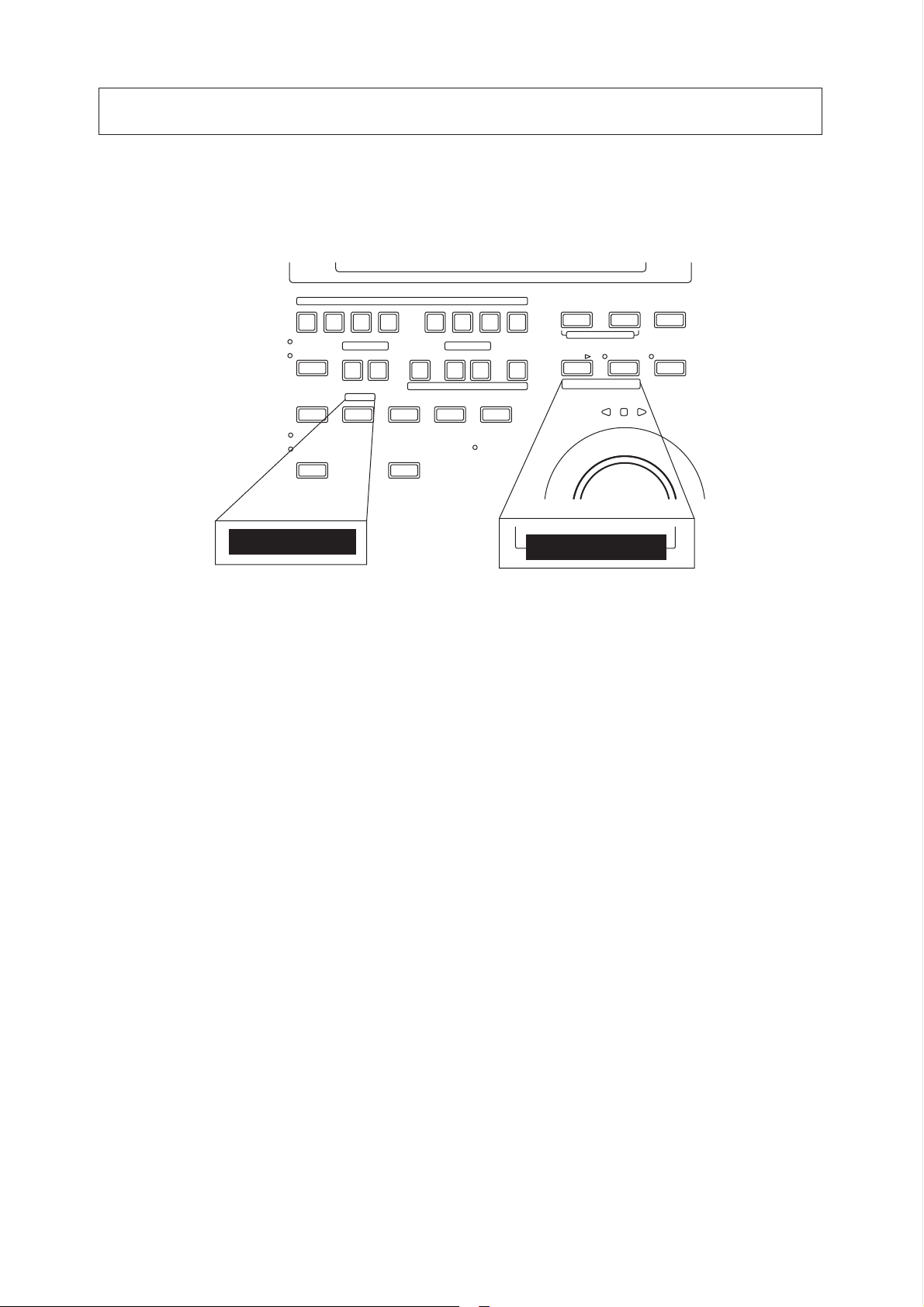
Part of the key function has been changed in Version 2.0. Be sure to place the "key name"
label included in the package as shown below. This label will allow you to identily each key
clearly and help you understand the explanation in this manual. Refer to the following
description regarding the changed key functions.
1/G1 2/G2 3/G3 4/G4 5/G1 6/G2 7/G3 8/G4 DISP SEL
AUTO RTN
AUTO PLAY IN OUT START IN OUT END
COPY PASTE ERASE
REHEARSAL
TAKE
AUTO PUNCH
COPY/MOVE
CLIPBOARD
RECORD TRACK
LOCATE
AUTO PUNCH
AUTO RTN
UNDO REDO
HD ACCESS
EXECUTE
TIMEBASE SEL
PGM CHANGE
/YES
EXIT
/NO
AECALLSTOREHOLD
The following functions have been added to the HOLD/> key, STORE key, and PASTE key.
1. Pressing the STORE key while holding down the HOLD/> key allows you
to select a Program. You can select a Program any time other than when
the recorder section is in REC mode or Play mode.
Refer to "Program Change function on the next page for details.
2. The Move & Paste function has been added to the PASTE key.
Using this key allows you to select whether you execute the Copy &
Paste function or the Move & Paste function. Refer to "Copy & Paste/
Move & Paste" on page 6 for details.
3
Page 4
DMT-8 Ver 2.0 Supplement to the Owner’s Manual
1. Program Change function
The Program Change function allows you to select any of five Programs (1-
5) to which the hard disk apace is allotted, so you can record, playback,
eddit, and archives up to five songs individually on a single hard disk (as
long as there is adequate free space on the disk). You can create an
individual song, so that for example the first song is in Program 1, the
second song in Program 2 etc.
To perform recording, playback , edit, and archives, first select a desired
Program.
How to switch a Program
* You can select a Program any time other than when the recorder
section is in REC mode or PLAY mode.
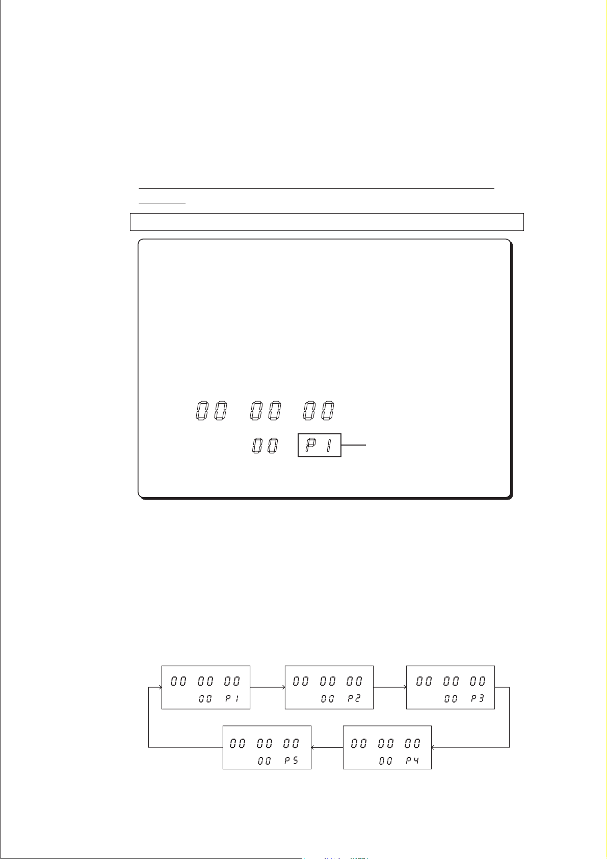
When you turn on the power to the DMT-8, a Program with the
Time Base used before you turned off the power will be selected.
(When you turn on the power to the unit for the first time after
unpacking, the DMT-8 will start with Program 1 with "ABS TIME"
base.) Make sure that the DMT-8 is stopped when you select a
Program.
ABS
HMPS
Displayed Program Number
Here, let’s assume that Program 1 with "ABS TIME" display was selected
when you turned on the power to the DMT-8.
1. While the screen shown above is displayed, pressing the STORE key
while holding down the HOLD/> key and repeatedly to switch Programs
from P1 through P5.
The following figure indicates that each Program with a Time Base of
"ABS" is selected.
ABS
HMPS
ABS
HMPS
ABS
HMPS
ABS
HMPS
ABS
HMPS
4
Page 5
DMT-8 Ver 2.0 Supplement to the Owner’s Manual
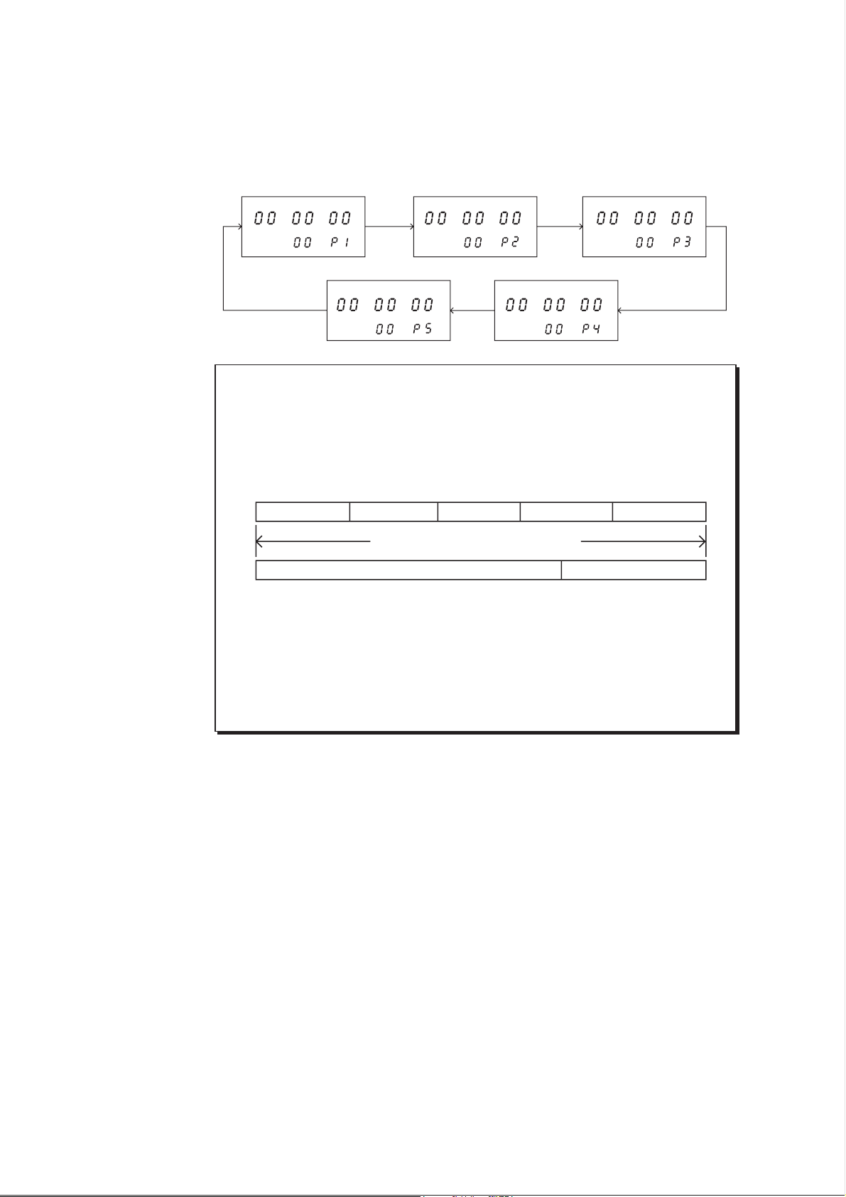
If the Time Base for each Program is different, something similar to the
following figure will appear. In this example, Program I has a Time Base of
"ABS Time", Program 2 with a Time Base of "BAR/BEAT/CLK", Program 3
with "MTC TIME", and Programs 4 and 5 with "ABS TIME".
ABS
HMPS
ABS
HMPS
ABS
HMPS
ABS
HMPS
ABS
HMPS
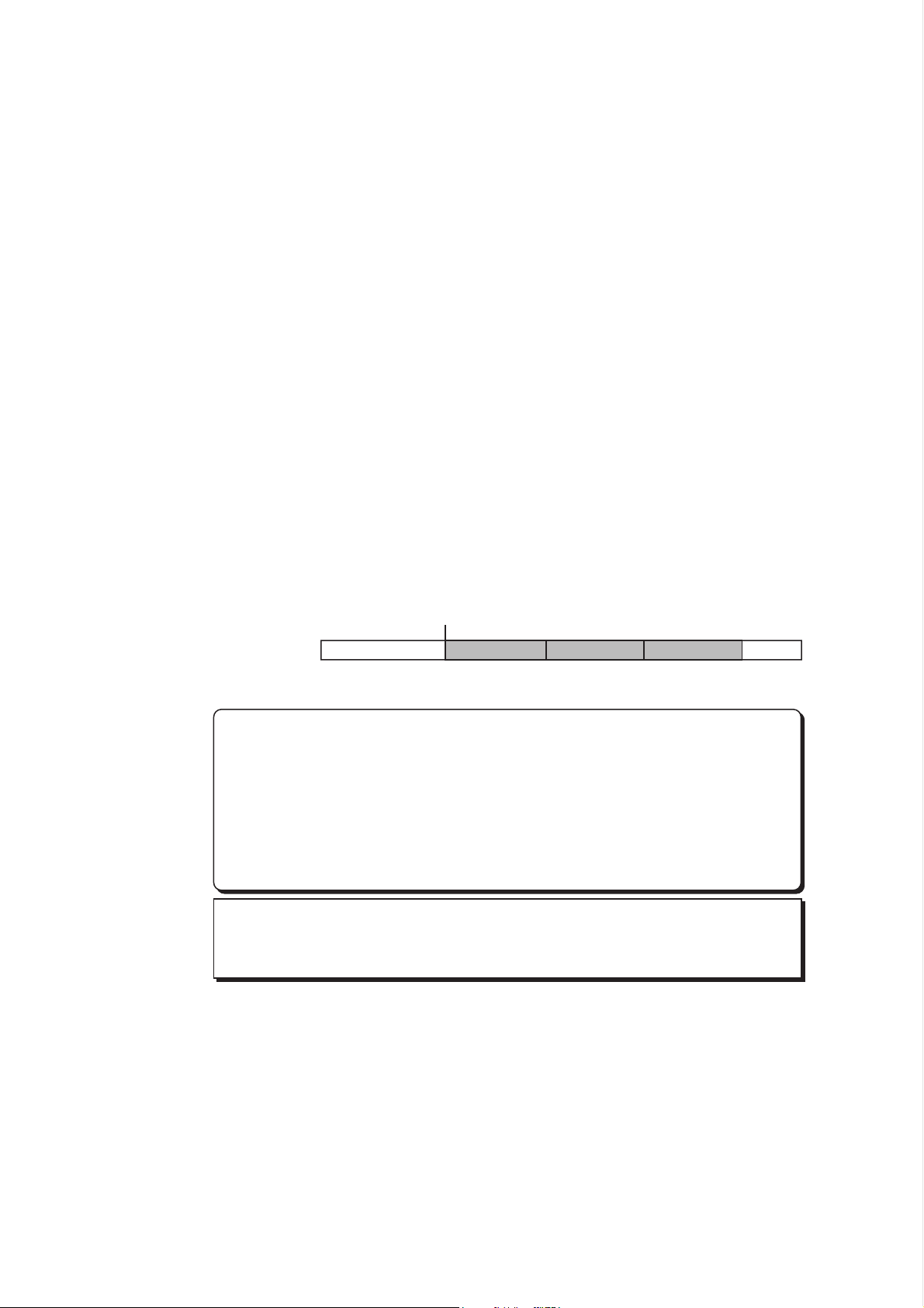
<Note>
You can record up to about 12.5 minutes total for all five Programs.
That is, if you have recorded one 12-minutes Program, you cannot
record anything in any other Programs as shown in the diagram below.
Check the REMAIN display for available recording time before recording.
Tune of program 1 Tune of program 2 Tune of program 3 Tune of program 4 Tune of program 5
Hard disk recordable time (approx. 12.5 min.)
Recordable time by program 2 - 5.Tune of program 1
<Note>
The new Program Change function has changed the way you use "SAVE"
in Setup mode as compared to the original explanation in the main
manual. refer to pages 15~18 of this supplement for detailed operation.
5
Page 6
DMT-8 Ver 2.0 Supplement to the Owner’s Manual
2. Copy & Paste and Move & Paste
A new Move & Paste function is available, in addition to the Copy & Paste
function.
Formerly, you could paste data in the copy source track. Now, you can also
paste in a track other than the Copy or Move source track. It is possible
to specify the number of times (0-99) you wish to paste the same data repeatedly.
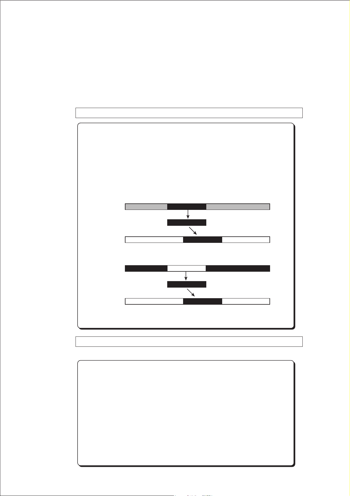
Difference between Copy & Paste and Move & Paste
* The Copy & Paste function pastes data (that is copied on the
Clipboards shown below) to any location of any track.
The copy source data remains intact.
* The Move & Paste function is almost the same as the Copy & Paste,
except that exciting the Move & Paste function will erase the move
source data (the Clipboard will be also cleared).
Clipboard In Point Clipboard Out Point
Source Track
COPY & PASTE
Paste Track
Auto Punch In Point
COPY
PASTE
Clipboard In Point Clipboard Out Point
Source Track
MOVE
MOVE & PASTE
PASTE
Paste Track
Auto Punch In Point
Procedure for Copy & Paste and Move & Paste
(The first two steps are same for either function.)
1. Store the copy start point (CLIPBOARD IN point) and the end point
(CLIPBOARD OUT point) to copy the data into the Clipboard, select
the copy source track, and press the COPY key.
2. Store the paste start point (AUTO PUNCH IN point) to specify
location to paste.
3. Pass the PASTE key, and select "Copy & Paste" or "Move & Paste".
(Pressing the PASTE key will toggle between these two points.) Select a
paste destination track, enter this number of repeat to paste, and
press the EXECUTE/YES key.
6
Page 7

Copying the data
* The following procedure is based on data with the ABS Time Base.
To change the Time Base to MTC or MIDI BAR/BEAT CLK, press
the DISP SEL key while pressing and holding down the EXECUTE/
YES key.
Specifying and storing the Start point (Clipboard In point)
1. Press the RECALL key, then the CLIPBOARD IN key (or predd only the
CLIPBOARD IN key) to enter edit mode.
2. Select the digit to edit using the HOLD/> key on the SHUTTLE dial, and
use the JOG dial to set a desired time value.
3. Press the STORE key, then the CLIPBOARD IN key.
The specified time will be stored at the CLIPBOARD IN key as the copy start
point (clipboard In point), and the DMT-8 will quit edit mode, displaying the
previous screen.
* You can store the start point in real-time instead of following Steps
1-3 described above. (While playing back the data, predd the
STORE key, the CLIPBOARD IN key.)
DMT-8 Ver 2.0 Supplement to the Owner’s Manual
Specifying and storing the End point (Clipboard In point)
4. Press the RECALL key, then the CLIPBOARD OUT key (or predd only the
CLIPBOARD OUT key) to enter edit mode.
5. Select the digit to edit using the HOLD/> key or the SHUTTLE dial, and
use the JOG dial to set a desired time value.
6. Press the STORE key, then the CLIPBOARD OUT key.
the specified time will be stored at the CLIPBOARD OUT key as the copy end
point (Clipboard Out point), and the DMT-8 will quit edit mode, displaying
the previous screen.
* To check to see if the correct In/Out points have been stored, press
the CLIPBOARD IN/CLIPBOARD OUT keys. The display will
show the stored time value.
Hints;
When you are sorting the In/Out points in real-time while using the
"BAR/BEAT/CLK" Time Base, you can store then in steps of beats
if the "rESoLu" (Display Resolution mode On/Off) in Setup mode
is "ON". When this resolution mode is "ON" the CLK value will be
rounder up or off to "00" (at the beginning of the data) as soon as
you press the STORE key.
This function is useful when you wish to use the Copy & Paste or
Move & Paste function in steps of beats.
Refer to page 23 of this supplement for detailed operation.
7
Page 8

DMT-8 Ver 2.0 Supplement to the Owner’s Manual
Copying
7. Select a copy source track using the RECORD TRACK select key.
* You can select a mono track or multiple tracks.
When using the Copt & Paste or Move & Paste function, however, you
can change the paste destination track only when you have selected a
mono track, or an odd-numbered track and the adjacent even numbered track (i.e.; 1-2, 3-4, 5-6, 7-8).
If you have copied multiple tracks (other than the above combination),
the data will be pasted to the copy source tracks. (track 1 -> track 1....
.....track 3 -> track 3 etc.)
8. Press the COPY key.
The data will be copied immediately. The display will show Copy Clip", the
"COMPLETED!" and returns to the previous screen.
Now, the specified sound data has been copied onto the Clipboard as paste
data. Follow the procedure below to use the Copy & Paste operation, or the
Move & Paste operation.
* The setups up to here apply to both the Copy & Paste function and
the Move & Paste operation, since you will eventually select one of
the functions before you press the PASTE key.
< Note>
If you press the COPY key without selecting a copy source track by the
RECORD TRACK select key, the display will show "SELECT trk" (meaning "select a track.") and return to the previous screen.
In this case, select a copy source track and try again to copy the data.
< Note>
If the Out point has been specified before the In point (the In point
value is the same or larger than the Out point value), the display will
show the error message "Void In" or "Void Out" and return to the
previous screen.
In this case, set correct In/ Out points and try again to copy the data.
< Note>
You can copy a set of data into the Clipboard. If you copy another set
of data, the existing data in the Clipboard will be over written by the
new one.
Checking the copied data
You can listen to the copied data on the Clipboard (Clipboard Play function).
To listen to the copied data, press the PLAY button while pressing and
holding down the STOP button (Clipboard Play mode).
The data will be played back from the beginning. To stop monitoring the
data, press the STOP button.
8
Page 9

DMT-8 Ver 2.0 Supplement to the Owner’s Manual
* During Clipboard Play mode, the indicator of the copied track will
blink and the selected Time Base will show the position of the copy
source.
Executing the Copy & Paste function
< Note >
You need enough unrecorded space on the hard disk to execute the
Copy & Paste operation.
If you press the EXECUTE/YES key to try to paste with insufficient
disk space, the display will immediately show the error message
"Over time", then show the excess time using the currently-selected
Time Base (time or bar). In this case, shorten the copy data by the
amount of excess time. Alternatively, move ABS END backward using
the CUT function as described in page 89 of the DMT-8 main manual
in order to obtain more free space on the disk.
< Note >
You can select Copy & Paste destination tracks other than the copy
source track only when you have selected a mono track, or an oddnumbered track and the adjacent even-numbered track (i.e.; 1-2, 3-4,
5-6, 7-8) as source tracks.
If you have copied tracks other the above combination, such as 1-5 or
3-8, the data will be copy & pasted to the copy source tracks.
Specifying and storing the copy & paste start point (Punch In point)
This start point can be used for both Copy & Paste operation and Move & Paste
operation.
1. Press the RECALL key, then the AUTO PUNCH IN key (or press only the
AUTO PUNCH IN key) to enter edit mode.
2. Select the digit to edit using the HOLD/> key or the SHUTTLE dial, and
use the JOG dial to set a desired time value.
3. Press the STORE key, then the AUTO PUNCH IN key.
The specified time will be stored as the paste start point, and the DMT-8 will
quit edit mode, displaying the previous screen.
* To check to see if the correct In point have been stored, press the
AUTO PUNCH IN key. The display will show the stored time value.
Executing the Copy & Paste operation
* The data on the Clipboard remain unchanged after you execute the
Copy & Paste operation. Therefore, you can paste the same data as
many times as you wish. (However, the data on the Clipboard will
be cleared after executing the Move & Paste operation.)
9
Page 10

DMT-8 Ver 2.0 Supplement to the Owner’s Manual
4. Press the PASTE key.
Pressing the key repeatedly will change the display indication in the following
order; "coPy PASt" ->-> (after one second) ->-> "rPt 01 PASt ARE YOU SURE?"
(ready for the Copy & Paste operation), alternatively "movE PASt" ->-> (after
one second) ->-> "rPt 01 movE ARE YOU SURE?" (ready for the Move & Paste
operation). In this procedure, select "rPt 01 PASt ARE YOU SURE?" to execute
the Copy & Paste operation. The copy source track number will light up, and
"01" will blink indicating that the number of repeats to paste is "one".
5. Specify the copy destination track and the number of repeats to paste.
* Specifying the copy & paste destination track;
select the destination track using the RECORD TRACK select key. (You do
not need to specify the track if you are going to copy & paste data in the
copy source track.)
* Specifying the number of repeats to copy & paste;
Turn the JOG dial to change the blinking number "01" to any value between
01 and 99. (If there is not enough free space on the hard disk, the repeat
time will be limited to a number less than 99, and you will be enable to
specify a larger number when you turn the JOG dial.)
6. Press the EXECUTE/YES key.
The upper row of the display will show the time taken for the Copy & Paste
operation, then "CoPY", "PASt", then "COMPLETED!". Press the EXIT/NO
key to go back to the previous screen.
Now the audio data on the Clipboard has been pasted to the specified track
stating with the AUTO PUNCH IN point.
For example, executing the function with a repeat number of "rPt 03"
(three times)will paste the data as shown in the diagram below.
Auto Punch In Point
Repeat number of "03"
123
* To cancel the Copy & Paste operation, press the EXIT/NO key when
the display blinks the "ARE YOU SURE?" massage. If you wish to
abort the Copy & Paste operation after you have pressed the
EXCUTE/YES key, press the STOP button or the EXIT/NO key
before the display show "COMPLETE!" medicating completion of the
Copy & Paste operation.
If you cancel or abort the Copy & Paste operation in these ways, no
part of the copied data will be pasted. (Even if you abort an
operation in progress, nothing will be pasted.)
< Note>
After you copy & paste data onto any part of the copy source data,
if you wish to redo the Copy & Paste operation, erasing the pasted
part will also change the original copy source data. (Refer to page 88
of the main manual for details.)
If you wish to redo the Copy & Paste operation, do not erase the paste
part, instead, be sure to undo the operation.
10
Page 11

DMT-8 Ver 2.0 Supplement to the Owner’s Manual
Undo/Reedo Copy & Paste
You can cancel the Copy & Paste operation by pressing the UNDO key.
Pressing the REDO key after pressing the UNDO key will restorer the data
that was obtained before undoing the operation (that is, you can restore
the status obtained after the first Copy & Paste operation).
Pressing the UNDO/REDO keys will cause the display to show "COMPLETED",
then return to the previous screen.
< Note >
The Undo/Redo functions are effective only while the DMT-8 is
stopped. They are not available in any other mode.
< Note >
The Undo/Redo functions are not effective in the following situations;
[1] After new recording
[2] After new editing (such as copy & paste, move & paste,
erase, and cut)
[3] When the Auto Punch In point is passed during playback
or recording with Auto Punch In mode set to ON
[4] When you turn the power off and on
Using the Move & Paste function
< Note >
You need enough unrecorded spectre on the hard disk to execute the
Move & Paste operation or the Copy & Paste operation. (The alarm
message "Over timE" and the soution of the Copy & Paste operation
will apply to the Move & Paste operation.)
< Note >
The same restriction as the Copy & Paste function applies to the
Move & Paste operation between the different tracks. (Refer to the
section explaining the Copy & Paste function for more details.)
As in the Copy & Paste operation, copy the data into the Clipboard, and store
the paste start point (Auto Punch In point). (Refer to the Copy & Paste section
for a detailed procedure.)
* The steps up to this point are exactly the same as for Copy & Paste
operation.
Exciting the Move & Paste operation
1. Press the PASTE key.
Pressing the key repeatedly will change the display indication in the following
order; "coPy PASt" ->->(after one second) ->-> "rPt 01 PASt ARE YOU SURE?"
(ready for the Copy & Paste operation), alternatively "movE PASt" ->-> (after
one second) ->-> "rPt 01 movE ARE YOU SURE?" (ready for the Move & Paste
operation). In this procedure. select "rPt 01 movE ARE YOU SURE?" to execute
the Move & Paste operation. The copy source track number will light up, and
"01" will blink, indicating that the number of repeats to paste is "one".
11
Page 12
DMT-8 Ver 2.0 Supplement to the Owner’s Manual
2. Specify the move destination track and the number of repeats to paste.
* Specifying the move & paste designation track;
Select the destination track using the RECORD TRACK select key. (You do
not need to specify the track if you are going to move & paste data in the
copy source track.)
* Specifying the number of repeats to move & paste;
Turn the JOG dial to change the blinking number "01" to any value between
01 and 99. (if there is not enough free space on the hard disk, the repeat
time will be limited to a number less than 99, and you will be unable to
specify a large number when you turn the JOG dial.)
3. Press the EXECUTE/YES key.
The upper row of the display will show the time taken for the Move & Paste
operation, then "MoVE", "PASt", then "COMPLETED!", Press the EXIT/NO key to
go back to the previous screen.
Now the audio data on the Clipboard has been pasted to the specified
track starting with the Auto Punch In point.
Unlike the Copy & Paste operation, executing the Move & Paste function
will erase the original data and the data on the Clipboard.
For example, executing the function with a repeat number of "rPt 03"
(three times) will paste the data as shown in the diagram below.
Auto Punch In Point
Repeat number of "03"
123
* To cancel the Move & Paste operation, press the EXIT/NO key when the
display shows blinks the "ARE YOU SURE?" message. If you wish to
abort the paste operation after you have pressed the EXECUTE/YES key,
press the STOP button or the EXIT/NO key before the display shows
"COMPLETED!", indicating the completion of the paste operation. If
you cancel or abort the press operation in these ways, no part of the
copied data will be pasted at all. (Even if you abort an operation in
progress, nothing will be pasated.)
< Note>
The data on the Clipboard will be cleared after the Move & Paste function
is executed. Therefore, you cannot paste the same data again.
12
Page 13

DMT-8 Ver 2.0 Supplement to the Owner’s Manual
Undo;/Reedo of the Mode & Paste function
You can use the Undo/Redo funcctions for the Move & Paste operation in
the same way as for the Copy & Paste operation.
< Note >
The Undo/Redo functions are effective only while the DMT-8 is stopped.
They are not available in any other mode.
< Note >
The Undo/Redo functions are not effective in the following situations;
[1] After new recording
[2] After new editing (such as copy & paste, move & paste, erase,
and cut)
[3] When the Auto Punch In point is passed during playback or
recording with Auto Punch In mode set to ON
[4] When you turn the power off and on
Notes on Cut/Erase
Follow the procedure in the main manual for the Cut/Erase function.
Also, follow the notes below:
< Note >
The Cut/Erase function is effective only for the currently-selected Program.
Be sure to check the Program number before executing this function.
< Note >
If you try to cut the data for a program in its entirety by storing the ABS 0
point at the Auto Punch In point, about 100ms of data may remain at the
beginning.
In this case, us the Erase function to erase the unnecessary part. (The
Erase function can erase data that was not deleted by the Cut function.)
13
Page 14

DMT-8 Ver 2.0 Supplement to the Owner’s Manual
3. Changed and Added functions in Setup mode
The following paragraphs regarding Setup mode explain changed or added
functions in Version 2.0.
* "SAvE" (saving data to an external DAT recorder) has been extended.
Now you can select whether you wish to save only the currently-selected Program
or all the Programs (Programs 1-5).
* "MTC OFFSET" (setting an MTC offset value) precision has been improved.
You can set the MTC offset value in sub-frame units.
* "dG in" (selecting a digital input channel) has been added.
You can route digital signals from thee DATA IN connector (16-bit, 44.1kHz, S/P DIF
format) to any two tracks for digital recording.
* "dG out" (selecting a digital output channel) has been added.
You can select Tracks 1-2, 3-4, 5-6, 7-8 or mixer stereo L/R outputs signals from
the DATA OUT connector (16-bit, 44.1kHz, S/P DIF format).
* "SLAvE" (selecting Slave mode ON/OFF) has been added.
You can operate the DMT-8 in Slave mode by sending the MTC and digital signals
from the MIDI OUT connector of a master DMT-8 or D-80.
* "dEvicE" (selecting a device ID) has been added.
This function allows you to set receive device number (linked to the transmit device
number) used for controlling the DMT-8 via MMC (MIDI Machine Control) or FEX
(Fostex System Exclusive Message).
* "Undo" (selecting an effective range of the Undo function) has been added.
In addition to the Undo/Redo function for editing and for Auto Punch In/Out
recording, the Undo/Redo function for direct recording (normal recording
performed by pressing the REC button while holding down the PLAY button) is now
available.
14
Page 15

DMT-8 Ver 2.0 Supplement to the Owner’s Manual
The Setup menu has been divided into the two categories; "Setup menu
effective for each Program", and "Setup menu applied to all Programs".
◯●: Setup for each program
Indication Function Commonness Default setting
"BAR"
"TEMPO"
"CLIck"
"LOAD"
"SAvE"
"FORMAT"
"PREROLL TIME"
"MIDI SYNC OUT"
"FRAME RATE"
"MTC OFFSET"
"EnAbLE rEc"
"dG in"
"dG out"
"rE SoLu"
"SLAVE"
"dEvicE"
"undo"
Sets the time signature on the Tempo Map (selected from 11 signatures: 1/4 ~ 8/8).
Sets the tempo on the Tempo Map.
Tums the Metronome function on/off.
Loads a data file saved an a DAT to the DMT-8.
Saves recording/setup data from the hard disk to the DAT machine.
Initializes the hard disk.
Sets the preroll value for the locate point.
Selects the signal output form the MIDI OUT connector.
Selects the frame rate for MTC output.
Sets the offset value between MTC and ABS time.
Selects recording enable/disable.
Selecting a signal input channel.
Selecting a signal output channel/.
Setting Display Resolution mode ON/OFF.
Setting Slave mode ON/OFF.
Setting a device ID.
Setting an effective range of the Undo function.
: Effective against ALL
001 BAR 04 04 (Signature 4/4)
001 BAR 1, 120 (Tempo 120)
OFF
(*1)
(*2)
(*2)
Current Program
00S (00 second)
CLOCK (MIDI clock)
25 Frame
0H: 59M: 57S: 00F: 00SF
ENABLE (Can record)
L • (No assign) R • (No assign)
cH St (Mixer output L/R)
OFF
OFF
00 (Device No. = 00)
EDIT (Edit and Auto Punch)
* 1: Only the currently-selected Program, or Programs 1 ~ 5 will be saved.
* 2: The parameters will be set default when the power is turned off (as well as the locate memory).
* 3: You can set the Time Base for each Program individually.
3-1. Saving recorded data ("SAvE")
In Version 2.0, you can select whether you wish to save the currentlyselected Program, or all Programs 1-5 at once. If you save all Programs,
the process duration will be four times the total length of all Program data
to save them.
The following diagram shows the sequence of the Programs saved to the
DAT machine.
P1 -> (10 seconds between the songs) -> P2 -> (10 seconds between the
songs) -> P3 -> (10 seconds between the songs) -> P4 -> (10 seconds between
the songs) -> P5
Data outpoint pattem when "SAvE ALL (saving all Programs 1-5)" is selected:
Gray: Setup data (You will hear the deep.)
Black: Audio data (You will hear the audio data.)
White: Non data (Non recorded area.)
Tr 1&2 Tr 3&4 Tr 5&6 Tr 7&8
Program 1 (P1) Program 2 (P2) Program 5 (P5)
10 seconds
10 seconds
< CAUTION >
You can save all Programs 1-5 at once, but you cannot load them back to
the DMT-8 at once. (You can load Programs one by one.) For details, refer
to the "Loading from the DAT Machine (LOAD) "for details.
15
Page 16

DMT-8 Ver 2.0 Supplement to the Owner’s Manual
Saving data to DAT (SAVE)
To save a single Program, select the Program. Assume that we have selected
Program 1.
1. Press the DISP SEL key to select "SETUP" and press the EXECUTE/YES
key. (The "SETUP" indicator will light up.)
Turn the JOG dial to select the blinking "SAVE" option, and press the
EXCUTE/YES key.
The display will change as shown below, and the Program number currentlyselected ("P1" in this example) will blink. At this time, you can select whether
you wish to save only this Program, or to save all Programs. Turn the JOG dial
cclockwise to select "ALL" or counter-clocckwise to select "P1".
12 34 567 8 L R
12 34 567 8 L R
OVER
OVER
0
3
6
9
12
18
24
30
0
3
6
9
12
18
24
30
SET UP
SLAVE
SET UP
SLAVE
Blink
Blink
2. Press the EXECUTE/YES key again.
The display will change to something like this, and the DMT-8 will enter Save
Standby mode.
12 34 567 8 L R
OVER
0
3
6
9
12
18
24
30
SET UP
ARE YOU SUAR ?
SLAVE
Blink
3. Start recording on the DAT machine, and press the EXECUTE/YES key on
the DMT-8 again.
As soon as the saving operation starts, the display will show the time taken for
the save operation and count down. (The follwing example shows that the saving
operation will take 18 minutes and 58 seconds.)
12 34 567 8 L R
OVER
0
3
6
9
12
18
24
30
REMAIN
SET UP
SLAVE
MS
16
Page 17

DMT-8 Ver 2.0 Supplement to the Owner’s Manual
* You process duration is about four times the length of the auto data of a
Program. For example, if the Program is a song of four minutes, saving
it will take about 16 minutes. The process of saving all Programs will
take four times the total length of all Programs.
4. When the saving operation is completed, the display will show
"COMPLETED!" and the DMT-8 will automatically quit Setup mode.
* To abort the save operation, press the STOP button or the EXECUTE/
YES key. Pressing the STOP button or the EXECUTE/YES key repeatedly
will take you back to the previous stage and allow you to select other
parameters or quit Setup mode.
Loading from the DAT machine
< Note>
You can save Programs 1-5 simultaneously, but you cannot load them back
to the DMT-8 simultaneously. (You can load Programs one by one.) To load
data, first select the Program number, then send the data of the song from
the DAT, (Only one song can be loaded into each Program.)
Refer to the diagram in the previous section entitled "Data output pattern"
when "SAVE ALL (saving all Programs 1-5)" is selected: " and understand
the audio data output pattern before locating the beginning of the song
you want to load to the DATA tape. (ex: Refer to the diagram below if you
are loading Program 3 data from the DAT into Program 1.)
Program 1 Program 2 Program 3 Program 4 Program 5
Playback DAT
12 3 45
Select "P1" by
Program Change
functio.
Press the EXCUTE/
YES key, while in the
"LOAD" blink state.
Press the EXCUTE/
YES key, again.
Stop DAT
Load data.
Load will be completed
and "COMPLEDED!"
will be lit.
1. Press the STORE key while pressing and holding down the HOLD/> key
to select a Program you wish to load.
2. Locate a position a little before the beginning of the data on the DAT
tape (preroll). (If the data begins from the top of the tape, rewind the
tape all the way.)
3. Press the DSP SEL key select "SETUP" and press the EXECUTE/YES key.
(The "SETUP" indicator will light up).
Turn the JOG dial to select the blinking "LOAD" option, and press the EXECUTE/
YES key. The display will change as show below, and the DMT-8 will enter Load
Standby mode.
17
Page 18

DMT-8 Ver 2.0 Supplement to the Owner’s Manual
12 34 567 8 L R
OVER
0
3
6
9
12
18
24
30
SET UP
ARE YOU SURE ?
LOAD
Blink
DIGITAL IN
< Note>
If the optical cable is not connected to the DATA IN/OUT connector, or a
correct signal (digital clock) is not supplied to the DMT-8, the display will
blink the message "DIGITAL IN", indicating that you cannot load data.
In this case, check the optical cable connection, the DATA output settings,
and the content of the DAT tape.
4. Press the EXECUTE/YES key again.
The message "PLAY dAt" starts blinking on the display. Play back the DAT tape
from the preroll position.
As soon as the loading operation starts, the display will show the time taken for
the load operation, then count down. The data will be loaded to the currently selected Program.
12 34 567 8 L R
12 34 567 8 L R
OVER
OVER
0
3
6
9
12
18
24
30
0
3
6
9
12
18
24
30
SET UP
LOAD
REMAIN
SET UP
LOAD
DIGITAL IN
M S
DIGITAL IN
Blink
* To abort the load operation, press the STOP button or the EXIT/NO key.
When you press one of these keys, the load operation will be aborted
and the DMT-8 will automatically quit Setup mode.
< CAUTION>
Once the loading operation starts, aborting the peroration in progress will
erase all existing data in the Program, and data up until the moment of the
abort will be loaded.
For example, if you have loaded two minutes of data into Program 1 (P1),
which already holds a six-minute song, the existing data after two minutes
will be erased. (The ABS END position of P1 is "two minutes".)
Make sure that you have selected the correct Program number before using
the Load function.
5. When loading is complete, the display will show "COMPLETED!" and the
DMT-8 will automatically quit Setup mode.
18
Page 19

DMT-8 Ver 2.0 Supplement to the Owner’s Manual
3-2. Setting the MTC offset time ("MTC OFFSET")
Available offset time range in Version 2.0 is 0H:00M:00S:00SF through
5H:59M:59S:29F:99SF. This setting is effective only in the selected Program.
3-3. Setting a digital input channel ("dG in")
Using "dG in" of Setup menu, you can assign any of the analog inputs 1-8
to digital inputs L and R. This assignment will allow you to record digital
data from an external digital device (such as CD, MD, etc.) to the DMT-8
through DATA IN. (You can record data directly to the hard disk, without
using an A/D converter.) This setting will be shared by all Programs.
Turning the power off will set this setting to "OFF".
1. Press the DISP SEL key to select "SETUP" and press the EXECUTE/YES
key. (The "SETUP" indicator will light up.) Turn the JOG dial to select
the blinking "dG in".
The display will change to something like this, and the current value will appear.
(The default setting is "L -", "R -", indicating that both are off.)
12 34 567 8 L R
OVER
0
3
6
9
12
18
24
30
SET UP
Blink
2. Press the EXECUTE/YES key again.
Letter "L -" on the display will blink, and you can now edit the value.
12 34 567 8 L R
OVER
0
3
6
9
12
18
24
30
SET UP
Blink
3. Use the SHUTTLE dial to select blinking "L -" or "R -", and turn the JOG
dial to input numeric data (1-8).
4. Press the EXECUTE/YES key again.
The display in Step 1 will appear, and the setting is complete.
5. Press the STOP button or the EXIT/NO key to quit Setup mode.
< CAUTION >
You cannot use the tracks for analog recording iff they are assigned to digital
input. Therefore, return this parameter to the "OFF" setting after digital
recording is complete.
< Note >
If you assign the same track to both digital inputs L and R, the L channel will
have priority and the R channel will automatically be "OFF".
19
Page 20

DMT-8 Ver 2.0 Supplement to the Owner’s Manual
Recording digitally from an external device
DATA IN
DMT-8
OPTICAL OUT
Digital Equipment
(CD player or MD player)
1. Connect an optical cable to the DMT-8’s DATA IN and to the OPTICAL
OUT connector on the external digital device (CD player or MD player).
If the external digital device has only coaxial connectors for digital output, use
an optical COP-1 (optical/coaxial converter).
2. Pressing the STORE key while holding down the HOLD/> key allows you
to select a recording Program.
3. Assign a recording track in "dG in" of Setup mode on the DMT-8.
If digital signal is being input correctly, the display will show the illuminated
message "DIGITAL IN". If the signal input is incorrect, this message will blink.
4. Press the RECORD TRACK select key for the track you selected in Step 3,
and the display will show "READY".
5. Confirm that "DIGITAL IN" on the display is lit, and press the RECORD
button while holding down the PLAY button on the DMT-8 to start
recording.
You do not have to adjust the digital recording level.
6. Start playing back data on the external digital device.
7. When recording is complete, press the STOP button on both the DMT-8
and the digital device.
* Refer to next page "<Note> Important" for details.
20
Page 21

DMT-8 Ver 2.0 Supplement to the Owner’s Manual
< WARNING >
* Important !*
After digital recording is complete, or during the time when you are not
performing digital recording, set the digital input L/R channels to " -" (no
assing).
If the digital input channels remain assigned to the tracks and you set the
tracks in recording mode (or in input monitoring mode), abnormal digital
signals ("DIGITAL IN" is blinking) may cause the digital signals to from loops
and oscillate internally, leading to possible damage to the external speakers.
* Important !*
After completing digital recording, if you wish to continue a different digital
recording session, make sure to supply correct digital signals to the DMT-8
unitl a series of digital recording sessions is finished. (Do not remove the
optical cable or turn the power to the external device during the session.)
When you are performing a new digital recording session (or input
monitoring), abnormal digital signals ("DIGITAL IN" is blinking) may cause
the digital signals to from loops and oscillate internally, leading to possible
damage to the external speakers.
< Note >
It is prohibited by law to record and use any piece of music for which
copyright is possessed by a third party for commercial purpose - such as
contents, broadcasting, and sales - any purpose other than for your personal
pleasure.
3-4. Setting a digital output channel ("dG out")
Using "dG out" of Setup menu, you can assign any of analog outputs 1-8 to
digital output L or R. Select any one combination from "1-2", "3-4", "5-6",
"7-8", and "s t" (DMT-8 stereo output L/R).
This assignment will allow you to record digital data from the DMT-8’s
DATA OUT to an external digital device (such as CD, MD, etc.)
This setting will be shared by all Programs. The dealt setting is "s t"
(DMT-8 stereo output L/R). Tuning the power off will set this setting to
default.
1. Press the DISP SEL key to select "SETUP" and press the EXECUTE/YES
key. (The "SETUP" indicator will light up.) Turn the JOG dial to select
blinking "dG out".
The display will change to something like this, and the current value will appear.
(The default setting is "cH s t".)
12 34 567 8 L R
OVER
0
3
6
9
12
18
24
30
21
Blink
SET UP
Page 22

DMT-8 Ver 2.0 Supplement to the Owner’s Manual
2. Press the EXECUTE/YES key again.
The letter "cH s t" on the display will blink, and you can now edit the value.
12 34 567 8 L R
OVER
0
3
6
9
12
18
24
30
SET UP
Blink
3. Use the JOG dial to select from "1-2", "3-4", "5-6", "7-8", and "s t".
4. Press the EXECUTE/YES key again.
The display in Step I will appear, and the setting is complete.
5. Press the STOP button or the EXIT/NO key to quit Setup mode.
Recording digitally an external device
DATA OUT
OPTICAL IN
Digital Equipment
DMT-8
1. Connect an optical cable to the DMT-8’s DATA OUT and to the OPTICAL
IN connector on an external digital device (DAT or MD player).
If the external digital device has only coaxial connectors for digital input, use
an optical COP-1 (optical/coaxial converter).
2. Pressing the STORE key while holding down the HOLD/> key allows you
to select an output Program.
3. Assing an output track in "dG out" of Setup mode on the DMT-8.
If you select tracks "1-2", "3-4", "5-6", "7-8", the add number track will be
assigned to digital output R channel.
4. Start recording on the external digital device.
5. Press the PLAY button on the DMT-8 to start playing back data.
6. When recording is completed, press the STOP button on both the DMT 8 and the digital device.
22
Page 23

DMT-8 Ver 2.0 Supplement to the Owner’s Manual
3-5. Setting Display Resolution mode On/Off ("rESoLu")
"rESoLu" in Setup menu allows you to turn Display Resolution mode on
and off. When you are storing the In/Out points in real-time while using
the "BAR/BEAT/CLK" Time Base, you can store them in steps of beats if the
"rESoLu" (Display Resolution mode On/Off ) in Setup mode is "ON".
When this resolution mode is "ON", the CLK value will be rounded up or
off to "00" (at the beginning of the beat) as soon as you press the STORE
key. This function is useful when you wish to use the Copy & Paste or
Move & Paste function in setup of beats.
This setting will be shared by all Programs and maintained after you turn
off the power.
* For example, if you to store value "001 BAR", "1 BEAT", "46 CLK" as the
copy start point, and "002 BAR", "4 BEAT", "51 CLK" as the end point while
using the BAR/BEAT/CLK Time Base, these value will be stored as follws
when they are held if Display Resolution mode has been set to on:
The following example uses a signature of 4/4.
"001 BAR", "1 BEAT", "46 CLK" -> "001 BAR", "1 BEAT", "00 CLK" (CLK value is cut off.)
"002 BAR", "4 BEAT", "51 CLK" -> "003 BAR", "1 BEAT", "00 CLK" (CLK value is rounded up.)
1. Press the DISP SEL key to select "SETUP" and press the EXECUTE/YES
key. (The "SETUP" indicator will light up.) Turn the JOG dial to select
blinking "dG out".
The display will change to something similar to this, and the current value will
appear. (The default setting is "oFF".)
12 34 567 8 L R
OVER
0
3
6
9
12
18
24
30
SET UP
Blink
2. Press the EXECUTE/YES key again.
Letters "oFF" on the display will blink, and you can now edit the value.
12 34 567 8 L R
OVER
0
3
6
9
12
18
24
30
SET UP
Blink
3. Use the JOG dial to select "oFF" or "on".
Turning the JOG dial counter-clockwise will select "oFF", and turning it clockwise
will select "on".
4. Press the EXECUTE/YES key again.
The display in Step I will appear, and the setting is complete.
5. Press the STOP button or the EXIT/NO key to quit Setup mode.
23
Page 24

DMT-8 Ver 2.0 Supplement to the Owner’s Manual
3-6. Setting Slave mode On/Off ("SLAvE")
The "SLAvE" option in the Setup menu allows you to turn Slave mode on
and off. When this mode is on, the DMT-8 will be able to synchronize the
MTC (MIDI time code) sent from the master DMT-8 (or D-80). (Along with
the MTC, the master DMT-8 (or D-80) will send digital signals to the slave
DMT-8 as a reference).
This setting is effective only in the selected Program and will be maintained
after you turn off the power.
1. Press the DISP SEL key to select "STUP" and press the EXECUTE/YES
key. (The "SETUP" indicator will light up.) Turn the JOG dial to select
blinking "SLAvE".
The display will change to something similar to this, and the current value will
appear. (The default setting is "oFF".)
12 34 567 8 L R
OVER
0
3
6
9
12
18
24
30
SET UP
Blink
2. Press the EXECUTE/YES key again.
The letters "oFF" on the display will blink, and you can edit the value now.
12 34 567 8 L R
OVER
0
3
6
9
12
18
24
30
SET UP
Blink
3. Use the JOG dial to select "oFF" or "on".
Turning the JOG dial counter-clockwise will select "oFF", and turning it clockwise
will select "on".
4. Press the EXECUTE/YES key again.
The display in Step 1 will appear, and the setting is complete.
5. Press the STOP button or the EXIT/NO key to quit Setup mode.
< Note >
The DMT-8 requires an external digital as well as an external MTC for its
slave operation. Therefore, connect the DATA OUT terminal off the master
DMT-8 or DMT-8 Version 2.0 (or D-80) to the DATA IN terminal of the slave
unit using an optical cable. (You do not need to set any other settings on
the master unit, since the master unit’s DATA OUT connector always outputs
digital signal.)
If you have not connected the units as described above (or in the slave unit
does not receive digital signals correctly for some reason), the "DIGITAL IN"
indicator of the slave unit will blink, indicating an error.
24
Page 25

DMT-8 Ver 2.0 Supplement to the Owner’s Manual
Synchronizing multiple DMT-8s in Slave mode
If you connect one DMT-8 as a master with another DMT-8 as a slave, you
can realize a 16-input/16-track multitracker system.
MIDI IN DATA IN
DATA OUT
DMT-8
16-INPUTS (Analog Audio Signals)
DMT-8 (Slave)
1. Connect the DATA OUT connector of the master device with the DATA
IN connector of the slave device using an optical cable.
Connect the MIDI OUT of the master device with the MIDI IN of the slave service
using a MIDI cable.
2. Set "MIDI SYNC OUT" of Setup mode on the master device to "mtc", and
set "MTC OFFSET" and "FRAME RATE" to a desired value.
On the slave device, set "MTC OFFSET" and "FRAME RATE" to the same value as
those of the master device.
3. Set "SLAvE" of Setup mode on the Slave DMT-8 to "ON".
When "on" is selected, the PLAY LED will blink. (This means that Slave mode
has been set to "on" but synchronization has not been establisbed. When
synchronizarion is estalished, the LED will light up.)
After Slave mode of the DMT-8 (slave) is turned on, its "DIGITAL IN" will light
up once digital signal output from the DMT-7 (master)is read correctly. (The
message will blink if the signal is read incorrectly.)
< Note>
To operate two more DNT-8s in slave mode, use a commercially available
MIDI para box (thru box), and connect the MTC output of the master DMT8 to the MIDI IN terminal of the other two DMT-8s. Connent the DATA OUT
terminal of the first slave DMT-8 to the DATA IN terminal of the second
DMT-8 using an optical cable.
Checking the sync operation
1. Press the PLAY button to start playback on the master DMT-8.
The slave DMT-8 will read the MTC sent from the master DMT-8 correctly, and
the sync operation will start. The blinking "PLAY LED" will light up.
25
Page 26

DMT-8 Ver 2.0 Supplement to the Owner’s Manual
* You can perform normal recording and punch in/out recording on one
of the DMT-8s even if it is syncing the external MTC (and digital signals)
with Slave mode "ON".
You can also select any "MIDI SYNC OUT" setting regardless of the Slave
mode on/off status.
* The DMT-8 Rechase window is fixed at "10 frames". That is, if the digital
signal sent to the slave machine is interrupted (or if you try perform a
sync operation using only the MTC, without sending any digital signal),
the slave DMT-8 will continue operating synchronization as long as the
offset between the master and slave position is within 10 frames. However,
if the offset exceeds 10 frames, the slave machine will adjust the position
in relation to the master device position. (This is called a Rechase
operation".) Audio output will be muted during the rechase operation.
3-7. Setting MIDI device ID ("dEvicE")
The "dEvicE" in Setup menu allows you to set the device ID for controlling
the DMT-8 via MMC or Fostex System Exclusive Message sent from external
sequencing soft ware. (The transmit device ID is linked to this setting.)
The range of the device ID is 00 through 99. (However, if the device ID
number of the received message is "7F", the DMT-8 will follow this message
regardkess of the device ID setting.)
The setting will be shared by all Programs, and once you change this setting,
the change will apply to all Programs. This setting is maintained after you
turn off the power.
1. Press the DISP SEL key to select "SETUP" and press the EXECUTE/YES
key. (The "SETUP" indicator will light up.) Turn the JOG dial to select
the blinking "dEvicE".
The display will change to something similar to this and the current value will
appear. (The default setting is "00".)
12 34 567 8 L R
OVER
0
3
6
9
12
18
24
30
SET UP
Blink
2. Press the EXECUTE/YES key again.
"00" on the display will blink, and you can now edit the value.
12 34 567 8 L R
OVER
0
3
6
9
12
18
24
30
SET UP
Blink
3. Use the JOG dial to set the value between 00 and 99.
Turning the JOG dial counter-clockwise will decrease the value, and turning it
clockwise will increase it.
26
Page 27

DMT-8 Ver 2.0 Supplement to the Owner’s Manual
4. Press the EXECUTE/YES key again.
The display in Step 1 will appear, and the setting is complete.
5. Press the STOP button or the EXIT/NO key to quit Setup mode.
3-8. Setting the Undo function range ("Undo")
You can set an effective range for the Undo function in "Undo" in Setup
mode.
Two modes are available for the Undo function:
"Edit" : Non-destructive mode OFF - this mode allows for undo of auto punch
in/out, copy & paste, and move & paste, and "ALL". Non - destructive
mode ON - this mode allows for undo of all types of recording and editing.
< Note >
When executing direct recording in "undo ALL" mode, you need enough free
disk space to accommodate real time recording data. If you record a large
amount of data in this mode, the remaining disk space may run out during
your performance.
In this case, use the Undo function as soon as possible. (Once you perform
any edit operation, you will not be able to use the Undo function.) To maximize
the available disk space, cut an unnecessary part of another Programs, and
move the ABS END point of each Program backward as much as possible.
1. Press the DISP SEL key to select "SETUP" and press the EXECCUTE/YES
key. (The "SETUP" indicator will light up.) Turn the JOG dial to select
blinking "Undo".
The display will change to something similar to this, and the current value will
appear. (The detail setting is "Edit".)
12 34 567 8 L R
OVER
0
3
6
9
12
18
24
30
SET UP
Blink
2. Press the EXECUTE/YES key again.
The letters "Edit" on the display will blink, and you can edit the value now.
12 34 567 8 L R
OVER
0
3
6
9
12
18
24
30
SET UP
Blink
27
Page 28

DMT-8 Ver 2.0 Supplement to the Owner’s Manual
3. Use the JOG dial to select "Edit" or "ALL".
Turning the JOG dial counter-clockwise will select "Edit", and turning clockwise
will select "ALL".
"Edit" (Non-destrucive mode off)
"ALL" (Non-destrucive mode on)
The Undo function is effective only on the Auto Punch
In/Out, Paste, Erase, and Cut functions.
The Undo function is effective on normal recording as well
as the Auto Punch In/Out, Paste, Erase, and Cut functions.
4. Press the EXECUTE/YES key again.
The display in Step 1 will appear, and the setting is complete.
5. Press the STOP button or the EXIT/NO key to quit Setup mode.
4. Compatible with Fostex System Exclusive Message
As explained in the protocol section at the end of the manual, the DMT-8
Version 2.0 is compatible with "FEX" (Fostex System Exclusive Message),
which allows for high-quality control and communications via MIDI.
Refer to the protocol section for more details.
5. A new output function that merges MMC/FEX (Fostex System
Exclusive Message) and MTC internally.
The DMT-8 Version 2.0 will automatically and internally merge and send
the MMC and FEX from the MIDI IN connector to the MIDI OUT connector.
This function is useful when you wish to control the sync operation of two
DMT-8s from a computer.
In the example below, the master DMT-8 will merge the self-generated
MTC (that is sent to the slave DMT-8) with the MMC and FEX that are
output from the computer (along with the MMC/FEX reply message).
This merged signal is sent to the MIDI OUT connector, then to the slave
unit.
You can also select any "MIDI SYNC OUT" setting regardless of the Slave
mode On/Off status. In this example, the DMT-8 slave until will output the
sync signal selected by its "MIDI SYNC OUT" setting via the MIDI OUT
connector to the computer.
COMPUTER (slave)
with MMC, MTC
software
MIDI IN
DMT-8 Ver 2.0
(Master)
MIDI OUT
MIDI OUT MIDI IN
DATA OUT
MTC or MIDI CLOCK
DMT-8 Ver 2.0
(Slave)
MIDI IN
DATA IN
MIDI OUT
28
Page 29

DMT-8 Ver 2.0 Supplement to the Owner’s Manual
6. The maximum number of Tempo Map change points is new
64 for a time signature, and 64 for a tempo.
The older version had a maximum number of Tempo map change points
of 16 (time signature) / 32 (tempo). This number has been increased in
Version 2.0.
Thus is very useful when you wish to create a song that includes a lot of
time signature changes or frequent ritardandos or tempo. (You can set the
number of change points for each Program individually.)
The setting method has not changed.
29
Page 30

DMT-8 Ver 2.0 Supplement to the Owner’s Manual
Fostex MIDI System Exclusive Message Format for D-80/DMT-8
ver 2.0
< Note >
Following Protocol is effective only in equipment which will reply by Identity Reply=F0 7E<channel> 06 02 51 01 00 0A 00 01 00 7F 7F F7 (D-80)
Identity Reply=F0 7E<Channel>06 02 51 01 00 09 00 02 00 7F F7 (DMT-8 ver
2.0)
against the Inquiry Message=F0 7E<channel>06 01
Fostex System Exclusive Message
General Structure=F0 51<device id><sub id 1>(<data>)F7
* Numbers are all expressed in hexadecimal units.
Table: <sub id 1> (<data>)
Command or Model Set
Controller to D-80/DMT-8 ver 2.0
Loop on/off
Post locate
Auto rec
Lock enable
Copy clip
Copy paste
Erase
Cut
Clipboard play
Undo
Redo
Nondes. mode
Move clip
Move paste
Digital in ch.
Digital out ch.
Program change
Click on/off
12 22 (<on/off>)
12 28 (<post locate moded>)
12 2D (<on/off>)
12 41 (<lock enable>)
12 45 (<count><mmc track>)
12 46 (<count=01><repeat count>)
or
12 46 (<count><repeat count><mmc track>)
12 47 (<count><mmc track>)
12 48
12 49
12 4A
12 4B
12 4C (on/off) * Refer to Note 1.
12 4D (<count><mmc track>)
12 4E (<count=01><repeat count>)
or
12 4e (<count><repeat count><mmc track>)
13 41 (<channel><channel>)
13 42 (<channel><channel>) *refer to note 2.
13 43 (<program>)
13 44 (on/off)
Acknowledge or Status
D-80/DMT-8 ver 2.0 to Controller
32 2D (<edit message>)
32 45 (<edit message>)
32 46 (<edit message>)
32 47 (<edit message>)
32 48 (<sdit message>)
32 49 (<edit massage><mmc track>)
32 4A (<edit message>)
32 4B (<edit message>)
32 4D (<sdit message>)
32 4E (<edit message>)
30
Page 31

Status Request
DMT-8 Ver 2.0 Supplement to the Owner’s Manual
Status request command
Controller to D-80/DMT-8 ver 2.0
Loop op. status
Loop status
Post locate status
Auto rec status
Lock status
Copy clip status
Copy paste status
Erase status
Nondes. mode
Move clip status
Nove paste status
Digital in ch. st.
Digital out ch. st.
Program status
Click status
Level status
22 21
22 22
22 28
22 2D
22 41
22 45
22 46
22 47
22 4C
22 4D
22 4E
23 41
23 42
23 43
23 44
23 45
Status reply
D-80/DMT-8 ver 2.0 to controller
32 21 (<Loop op. mode = 12>)
32 22 (<on/off>)
32 28 (<post locate status>)
32 2D (<edit message>)
32 41 (<lock status>)
32 45 (<edit message=01 or =14>)
32 46 (<edit message=02><mmc time>)
or
32 46 (<edit massage=00>)
32 47 (<edit message=02><mmc time>)
or
32 47 (<edit message=00>)
32 4C (<on/off>)
32 4D (<edit message=01 or =14>)
32 4E (<edit message=02><mmc time>)
or
32 4E (<edit message=00>)
32 41 (<channel><channel>)
33 42 (<channel><channel>)
33 43 (<program>)
33 44 (<on/off>)
33 45 (<count=08><level data>)
< Note 1>
Nondes. mode:
Abbreviation for "non destructive recording mode". When this mode is ON, not
only "takes" made by various sound editing or AUTO PUNCH IN/OUT but "takes"
recorded by simultaneous pressing of the PLAY and RECORD buttons (direct
recording) will always be possible to UNDO (However, free disc memory space
equivalent to the recording length will always be required). This is the same
function of switching between "undo:ALL (Nondes.momde:on) <– –> Edit (Nomdes.
mode: off )" in the setup menu on the main unit.
< Note 2>
There is a limitation on specifying the <channel><channel> setting. For details,
refer to "Explanation on Command/Mode Set" mentioned in later pages.
EXPLANATION ON READ/WRITE INTO THE VARIOUS EDIT POINT MEMORY
The MMC response/information field "GP0~GP6" are allotted in the edit point
memories (clipboard in, clipboard out, auto punch in, auto ounch out memory, etc.)
which is necessary at editing. Therefore, at registering and readout of the edit point
memory, the "WRITE (40)" command and the "READ (42)" command of MMC must be
used. Relationship berween the Edit point memory of D-80/DMT-8 ver2.0 and GP0~
GP6 are shown below:
<Response/Information Field>
08 GP0 : locate memory
0A GP2 : clipboard out memory
0C GP4 : auto punch in memory
0E GP6 : end memory
09 GP1 : clipboard in memory
0B GP3 : start memory
0D GP5 : auto punch out memory
0F GP7 : reserved
31
Page 32

DMT-8 Ver 2.0 Supplement to the Owner’s Manual
Data Type
<loop op.mode>
<post locate mode>
<count>
<mmc track>
<edit message>
<mmc time>
<on/offf>
<repeat count>
<channel>
<lock enable>
<lock status>
<program>
<level data>
12=stop
Indicates the next operatinng mode following locating to the start point (GP3) upon
arriving at the end point (GP6) by the play mode. In D-80/DMT-8 ver2.0, 12=stop
only is effective.
12=stop
15=play
Specifies operating mode in which D-80/DMT-8 ver2.0 should enter pon
completung the locate operationi. Corresponds to the settinig of AUTO PLAY ON
("15")/OFF("12") on the main unit.
01~7F
Specifies succeeding data byte numbers.
Complies to the MMC (MIDI MACHIN CONTROL) standard track bit map. In D-80/
DDMT-8 ver2.0, you always need to specify two byte combinations of "r0" and "r1."
00 = no message
01 = completed (completion flag)
02 = active (executioin flag)
02<mmc time> = Indicates unprocessed time by active (execution flag) and <mmc
time>.
02<count><mmc track> = Indicates source track by acrive (execution flag)and
<mmc track>. Used for clipboard play.
03 = cancel (execution stop)
05 = Indicactes rehearsal (rehearsal mode of auto rec). Possible of undo.
06 = Indocates take (take mode of auto rec). Possible of undo.
10 = over value error
10<mmc time> = Capacity shortage time is indicated by over value erroe (error by
capacity shortage) and <mmc time>. In copy paste, it indicates capacty shortage
time required for a minimum one time paste.
11 = Indicates in point error (incorrect in point).
12 = Indicates out point error (incorrect out point).
14 = Indicates void data (data neccessary for paste does not exist).
18 = Indicates track select error (track necessary to execute copy/move) or erase/cut
is not correctl setup).
19<repeat count> = Indicates repeat number error and repeat number executable
by< repeat count>.
1A = Indicates disble rec (record disable mode).
25 = Indicates can undo rehearsal (rehearsal mode of auto rec). Impossible to
undo.
26 = Indicates can’t undo take (take mode of aauto rec). Impossible to undo.
71 = Indicates on.
72 = Indicates off.
hr mn sc fr {ff/st} complies to the MMC standard time code.
70 = default
71 = on
72 = off
01 ~ 7F
Especially when executing commands such as paste, the number of pasting times to
be continuously repeated following the auto punch in point is specified.
00 ~ 08
Selects tracks 1 ~ 8 of the reecorder sectioin. "00" means that no setup (sefalt setup)
is made.
00 = lock disable, chase disable
01 = lock enable, chase enable
Corresponds to SLAVE ON ("01")/OFF ("00") in the main unit.
00 = lock disable, chase disable
01 = lock enable (unloccked), chase enable (unlocked)
11 = lock enable (locked), chase enable (locked)
01 ~ 7F
Indicates program numbers (P1 ~ P5) on the main unit. However, D-80/DMT-8 can
specify only 01 (corresponds to P1) - 05 (corresponds to P5).
t1, t2 ...... tn
n: Indicates the track number.
tn: Indicates absolute 8 bits of the Auto 16 bit data (Range: 00~7F).
32
Page 33

DMT-8 Ver 2.0 Supplement to the Owner’s Manual
Explanation on the Command/Mode Set
12 22 (<on/off>): loop on/off command
The command for setting the "loop mode on/off" (=ON/OFF of AUTO RTN) of D-80/
DMT-8 ver2.0. Default figure of the loop operation mode is "12=stop" and this cannot be
changed.
12 28 (<post locate mode): post locate command
The command for setting the "post locate mode" (=ON/OFF of AUTO PLAY) of D-80/
DMT-8 ver2.0. It will stop after locating if "post locate mode=12." It will enter play after
locating if "posy locate mode=15."
12 2D (<on/off>): auto rec command
The command for setting "auto rec mode on/off" (=ON/OFF of AUTO PUNCH) of D-80/
DMT-8 ver2.0. Upon receiving this command, D-80/DMT-8 ver2.0 will immediately reply
the operating condition by sending "32 2D (<edit message>)".
12 41 (<lock enable>): lock enable command
The command for setting "slave mode on/off" (setup menu) of D-80/DMT-8 ver2.0.
12 45 (<count><mmc track>): copy clip command
When this command is received, D-80=DMT-8 ver2.0 will copy (multiple number of tracks
can be copied simultaneously) the sound data, as data for copy paste, from the preregistered clipboard-in point to the clipboard-out point in the track specified by
<mmc track>.
With completion of copying the data into the clipboard, D-80/DMT-8 ver2.0 will
immediately reply with "32 45 (<edit message=01 (completed)>)".
If copy cannot be executed due to improper figures of the pre-registered clipboard in/
clipboard out points or incorrect track section, the corresponding <adit message> will be
returned.
12 46 (<count=1><repeat count>): copy paste command
12 46 (<count><repeat count><mmc track>): copy paste command
When this command is received, D-80=DMT-8 ver2.0 will paste the sound data which
has been copied into the clipboard, on the same track from the pre-registered auto punch
in point ever, if the sound data length in the clipboard is less than 10ms, the specifying
the <repeat count> will be limited to "01."
Also, by specifying <mmc track>, paste can be executed on other tracks in mono (in one
track units) or stereo units (in combinations of tracks 1 & 2, 3 & 4, 5 & 6, 7 & 8).
Since time corresponding to length of the copy clipped sound data is required to complete
the copy paste operation, D-80/DMT-8 ver2.0 immediately replies with "32 46 (<edit
mcssage=02 (active)>)" after receiving the command.
Successively upon completing the paste operation, "323 46 (<edit message=01
(completed)> " is transmitted.
If paste cannot be executed due to improper figures of the pre-registed auto punch in
point, insufficient disc capacity, no sound data in the clipboard, etc., the corresponding
<editmessage> will be replied.
12 47 (<count><mmc track>): erase command
When this command is received, D-80=DMT-8 ver2.0 will erase the data (writes in "0"
data) in the section from the pre-registered auto punch in point through auto punch
out point in the track specified by <mmc track>. Since time corresponding to length of
the erase section is required to complete the erase operation, D-80/DMT-8 ver2.0 will
immcdiately reply by "32 47 (<edit message=02 (active)>)" after receiving the command.
33
Page 34

DMT-8 Ver 2.0 Supplement to the Owner’s Manual
After the completion of erase operation, "32 47 (<edit message=01 (completed)>)" will
be transmitted.
If erase cannot be executed due to improper figures of the pre-registered auto punch in
point/auuto punch out point, incorrect track section, etc., the corresponding edit message>
will be replied.
12 48: cut
When this command is received, D-80/DMT-8 ver2.0 will cut whole the section following
the pre-recorded auto punch in point under the assumption that whole the tracks are
nonrecorded section, With completion of the cut operation, this equipment will
immediately reply with "32 48 (<edit massage=01 (completed)>). "If cut is unexecutable
due to improper figure of the pre-registered auto punch in point, the corresponding
<edit message> will be replied.
12 49: clipboard play
When this command is received, D-80/DMT-8 ver2.0 will playback once from the head of
the sound data copied in the clipboard by the copy clip and move clip commands.
Immediately after receiving the command, D-80/DMT-8 ver2.0 will reply with "32 49
(<edit message=02 (active)><mmc track>)." The sound data track number is indicated
by (mmc track>.
Upon completion of playback, "32 49 (<edit message=01 (completed) is sent and clipboard
play is ended. If there is no sound data in the clipboard, "32 49 (<edit message=14(void
data)>)" will be sent and clipboard play operation will be interrupted.
12 4A: undo
Upon receiving this command, D-80/DMT-8 ver2.0 will revert to the condition prior to
editing copy paste, erase, move paste, cut redo operation. When completion of undo
operation, D-80/DMT-8 ver2.0 will reply with "32 4A (<edit message=01 (completed)>)."
If D-80/DMT-8 ver2.0 is not possible to undo, "32 4A (<edit message=00 (no message)>)"
will be replied.
12 4B: redo
When this command is received, D-80/DMT-8 ver2.0 will return to the condition prior to
undo operation.
With completion of redo operation, D-80/DMT-8 ver2.0 will reply with "32 4B (<edit
message=01 (completed)>).
If D-80/DMT-8 ver2.0 is not possible to redo, "32 4B (<edit message=00 (no message)>)"
will be replied.
12 4C: (<on/off>) : nondes.mode
The command for setting on/off of non destructive moded on D-80/DMT-8 ver2.0.
If <on/off> is set to "on," recording mode of D-80/DMT-8 ver2.0 will enter the non
destrucive mode, and if "off," in the destructive mode.
Nondes.mode:
Abbreviation for "non destrucive recording mode". When this mode is ON, not only
"takes" made by various sound editing or AUTO PUNCH IN/OUT but "takes" recorded by
simultaneous pressing of the PLAY and RECORD buttons (direct recording) will always be
possible to UNDO (However, free disc memory space equivalent to the recording length
will always be required). This is the same function of switching between "undo: ALL
(Nondes. mode: on)<– –> Edit (Nondes. mode: off)" in the setup menu on main unit.
34
Page 35

DMT-8 Ver 2.0 Supplement to the Owner’s Manual
12 4D (<count><mmc track>): move clip command
When this command is received, D-80/DMT-8 ver2.0 will copy (multiple tracks can be
copied simultaneously) the sound data from the pre-regisered clipboard in point to the
clipboard out point, as data for move paste operation.
With completion copying the data into the clipboard, D-80/DMT-8 ver2.0 will immediately
reply with "32 4D (<edit message=01 (completed)>)."
If copy cannot be executed by the reason of pre-registered improper clipboard in/clipboard
out point figures or incorrect track section etc., the corresponding <edit message> will
be replied.
12 4E(<count=1><repeat count>): move paste command
12 4E (<count><repeat count><mmc track>): move paste command
When this command is received, D-80/DMT-8 ver2.0 will paste the sound data which
have been move clipped in the clipboard, for the number of times specified by <repeat
count> on the same track from the pre-registered auto punch in point as the starting
point.
At the same time, the move clipped original sound data will be erased (data "0" is written
in). However, when sound data length in the clipboard is less than 10ms, specifying
the <repeat count> will be limited to "01."
Also, by specifying the <mmc track> paste operation can be executed on other tracks in
mono (one track unit) or stereo units (tracks 1 & 2, 3 & 4, 5 & 6, 7 & 8).
Since time corresponding to length of the move clipped sound data is required to complete
the move paste operation, D-80/DMT-8 ver2.0 will immediately reply with "32 4E (<edit
message=02 (active)>)" after receiving the command.
Following completion of the move paste operation, "32 4E (<edit message = 01
(completed)>)" will be sent.
If paste cannot be executed due to improper figures of the previously registered auto
punch in point, insufficient disc capacity, no sound data is in the clipboard, etc., the
corresponding <edit message> will be replied.
13 41 (<channel><channel>): digital in ch. select command
The command assigning the digital audio signal (S/P DIF) input from the D-80/DMT-8
ver2.0 DATA IN connector to the track specified by <channel>. The digital audio signal
L channel assignment point is specified by the first <channel> and the R channel
assignment point by the second ,channel> in the command. If the same figure is specified
for both <channels>, L channel will have priority and R channel will be "-" (invalid).
13 41 (<channel><channel>): digital out ch. select command
This command selects the source track for the digital audio signal (S/P DIF) output from
the D-80/DMT-8 ver2.0 DATA OUT connector.
Normally, the track specified by the first <channel> will be the digital audio signal L
channel data, and the track specified by the second <channel> will be the digital audio
signal R channel data. In this equipment, the five types - (<01><02>), (<03><04>),
(<05><06>), (<07><08>) and (<00><00>) -can only be set up. Also, when (<00><00>) is
specified, default (L:-, R-, No Assign) will be set up in D-80, and (L:L, R:R) will be set up in
DMT-8 ver2.0. Thus the mixer section stereo bus output will be assigned on DMT-8
ver2.0.
13 43 (<program>): program change command
The command for PROGRAM CHANGE of D-80/DMT-8 ver2.0
The present program number can be changed to the figure indicated by <program>.
35
Page 36

DMT-8 Ver 2.0 Supplement to the Owner’s Manual
13 44 (<on/off>): click on/off command
The command for setting the metronome on/off of D-80/DMT-8 ver2.0.
When ON is set, the metronome signal will be fed to the track 8 output (analog output
only) of D-80/DMT-8 ver2.0.
The Status Request Command
22 21: loop operation status request
The command inquiring the loop operation mode setup status.
D-80/DMT-8 ver2.0 will reply with "32 21 (<loop op. moded=12>)."
22 22: loop on/off status request
The command inquiring the loop on/off (=ON/OFF of AUTO RETURN) setup status.
D80/DMT-8 ver20. will reply with "32 22 (<on/off>)."
22 28: post locate status request
The command inquiring the post locate mode (ON/OFF of AUTO PLAY)setup status.
D-80/DMT-8 ver2.0 will reply with "32 28 (<post locate mode>)".
22 2D: auto rec status request
The command inquiring the auto rec mode setup status and this is replied by "32 2D
(<edit message>). Reply from D-80/DMT-8 ver2.0 against this status request will be
either one of the following:
<edit message> =05: Possible to undo rehearsal mode.
=06: Possible to undo take mode.
=25: Impossible to undo rehearsal mode.
=26: Impossible to undo take mode.
=72: off
22 41: lock status request
The command inquiring the slave on/off setup status and the lock status.
D-80/DMT-8 ver2.0 will reply with "32 41 (<lock status>)."
22 45: copy clip status request
The command inquiring the clipboard condition. If there is a copy paste data in the
clipboard, D-80/DMT-8 ver2.0 will reply with "32 45 (<edit message-01>).
If data in the clipboard is for move paste or there is no valid data in it, it will reply will
"32 45 (<edit message=14 (void data)>)."
22 46: copy paste status request
The command inquiring execution status of copy paste editing.
When this command is received, D-80/DMT-8 ver2.0 will reply with either "32 46 (<edit
message=02><mmc time>)" or "32 46 (<edit message=00>). <mmc time> indicates
unprocessed time until completion.
22 47: erase status request
The command inquiring execution status of erase.
When this command is received, D-80/DMT-8 ver2.0 will reply by either "32 47 (<edit
message=02><mmc time>)" or "32 47 (<edit message=00>)." <mmc time> indicates.
unprocessed time until completion.
36
Page 37

DMT-8 Ver 2.0 Supplement to the Owner’s Manual
22 4C: nondes.mode request
The command inquiring the non destructive mode status.
When this command is received, D-80/DMT-8 ver2.0 will reply with "32 4C (<on/off>)."
Nondes.mode:
Abbreviation for "non destructive recording mode". When this mode is ON, not only
"tales" made by various sound editing or AUTO PUNCH IN/OUT but "takes recorded by
simultaneous pressing of the PLAY and RECORD buttons (direct recording) will always be
possible to UBDO (However, free disc memory space equivalent to the recording length
will always be required), This is same function of switching between "undo:ALL
(Nondes.mode:on) <– –> Edit (Nondes.mode:off)" in the setup menu the main unit.
22 4D: move clip status request
The command inquiring the clipboard status. If there is a move paste on the clipboard,
D-80/DMT-8 ver2.0 will reply with "32 4D (<edit message=01>)." If data in the clipboard
is for copy paste or there is no valid data on it, "32 4D (<edit message=14 (void data)>)"
will be replied.
22 4E: move paste status request
The command inquiring the move paste execution status.
When this command is received, D-80/DMT-8 ver2.0 will reply with "32 4E (<edit
message= 02><mmc time>)" or "32 4E (<edit message=00>)." <mmc time> indicates
unprocessed time until completion.
23 41: digital in channel status request
The command inquiring the digital in channel setup status.
When this command is received, D-80/DMT-8 ver2.0 will reply with "33 41
(<channel><channel>)."
23 42: digital out channel status request
The inquiring the digital out channel setup status.
When this command is received, D-80/DMT-8 ver2.0 will reply with "33 42
(<channel><channel>)."
23 43: program status request
The command inquiring the presently operating program number.
When this command is received, D-80/DMT-8 ver2.0 will reply with "33 43 (<program>)."
23 44: click on/off status request
The command inquiring the metronome on/off status of D-80/DMT-8.
When this command is received, D-80/DMT-8 ver2.0 will reply with "33 44 (<on/off>)."
23 45: level status request
The command inquiring the present output level data of the 1~8 tracks. In D-80/DMT8 ver2.0, as the level data is updated about every 40msec.,inquiry in 40msec. units is
effective.
When this command is received, D-80/DMT-8 ver2.0 will reply with "33 45
(<count=08><level data)."
37
Page 38

DMT-8 Ver 2.0 Supplement to the Owner’s Manual
Explanation on the Status Reply
32 21 (<loop op.mode>): loop operation mode status
This is the reply against the "22 21" loop operation status request command.
<loop op.mode=12> is the only status data of D-80/DMT-8 ver2.0 and any other setting
is not permissible.
32 22 (<on/off>): loop on/off status
This is the reply against "22 22" loop on/off status request.
32 28 (<post locate mode>): post locate mode status
This is the reply against "22 28" post locate status request. <post locate mode=12 or 15>
is the only status data of D-80/DMT-8 ver2.0 and any other setting is not permissible.
32 2D (<edit message>): auto rec status
This is the reply against the "12 2S" auto rec command or the "22 2D" auto rec status
request.
32 41 (<lock status>): lock status
This is the reply against the "22 41" lock status request.
32 45 (<edit message>): copy clip status
This is the reply against the "12 45" copy clip command or the "22 45" copy clip status
request.
32 45 (<edit message>): copy paste status
32 46 (<edit message><mmc time>): copy paste status
This is the reply against the "12 46" copy paste command or the "22 46" copy paste
status request. <mmc time> indicates the unprocessed time until completion of copy
paste editing.
32 47 (<edit message>): erase status
32 47 (<edit message><mmc time>): erase status
This is the reply against "12 47" erase command or "22 47" erase status request.
32 48 (<edit message>): cut status
This is the reply against the "12 48" cut command.
32 49 (<edit message><mmc track>): clipboard play status
This is the reply against the "12 49" clipboard play command. If there is no sound data
in the clipboard, "32 49" (<edit message=14 (void data)>)" will be replied. <mmc track>
indicates the sound data track number.
32 4A (<edit message>): undo status
This is the reply against the "12 4A" undo command. Either <edit message=01 (completed)
or <edit message=00 (no message)> will be replied.
32 4B (<edit message>): redo status
This is the reply against the "12 4B" redo command. Either <edit message=01 (completed)>
or <edit message=00 (no message)> will replied.
32 4C (<on/off>): nondes.mode status
This is the reply against the "22 4C" nondes.mode status request.
38
Page 39

DMT-8 Ver 2.0 Supplement to the Owner’s Manual
32 4D (<edit message>): move clip status
This is the reply against the "12 4D" move clip command or "22 4D" mode clip status
request.
32 4E (<edit message>): move paste status
32 4E (<edit message><mmc time>): move paste status
The reply against the "12 4E" move paste command or the "22 4E" move paste status
request.
<mmc time> indicates the unprocessed time until completion of move paste editing.
32 41 (<channel><channel>): digital in channel status
This is the reply against the "23 41" digital in ch.st. request.
The first <channel> indicates the track number to which the L channel digital audio
signal from the DATA IN connector is assigned and the second <channel>indicates the
assigned track number for the R channel.
32 42 (<channel><channel>): digital out channel status
This is the reply against the "23 42" digital out ch.st. request.
It indicates that the track indicated by the first <channel> in the command is assigned to
the L channel output of the digital auto signal output from DATA OUT, and the track
specified by the second <channel> is assigned to the R channel output.
32 43 (<program>): program status
This is the reply against the "23 43" program status request.
<program> indicates the presently operating program number.
33 44 (<on/off>): click status
This is the reply against the "23 44" click status request.
It indicates the on/off setting of the metronome function.
33 45 (<count=08><level data>): level status
This is the reply against the "23 45" level status request and indicates the present track
1~8 output level data.
In D-80/DMT-8 ver2.0, as level data is updated 40msec., it will be effective if inquiry is
made in 40msec. units.
39
Page 40

FOSTEX COMPANY
3-2-35 Musashino, Akishima, Tokyo, Japan 196-0021
© PRINTED IN JAPAN MAR. 1996 8288 377 100 FX
 Loading...