

Page 1
Owner’s Manual
Model
20bit Dual Multi Effect Processors
8288 441 100
Page 2
DE-1 Owner’s Manual
CAUTION
RISK OF ELECTRIC SHOCK
DO NOT OPEN
CAUTION: TO REDUCE THE RISK OF ELECTRIC SHOCK,
DO NOT REMOVE COVER (OR BACK).
NO USER - SERVICEABLE PARTS INSIDE.
REFER SERVICING TO QUALIFIED SERVICE PERSONNEL.
"WARNING"
"TO REDUCE THE RISK OF FIRE OR ELECTRIC
SHOCK, DO NOT EXPOSE THIS APPLIANCE TO RAIN
OR MOISTURE."
SAFETY INSTRUCTIONS
1. Read Instructions - All the safety and operating instructions
should be read before the appliance is operated.
2. Retain Instructions - The safety and operating instructions should
be retained for future reference.
3. Heed Warnings - All warnings on the appliance and in the
operating instructions should be adhered to.
4. Follow Instructions - All operating and use instructions should
be followed.
5. Water and Moisture - The appliance should not be used near
water - for example, near a bathtub, washbowl, kitchen sink,
laundry tub, in a wet basement, or near a swimming pool, and
the like.
6. Carts and Stands - The appliance should be used only with a
cart or stand that is recommended by the manufacturer.
An appliance and cart combination should be moved with care.
Quick stops, excessive force, and uneven surfaces may cause
the appliance and cart combination to overturn.
7. Wall or Ceiling Mounting - The appliance should be mounted to
a wall or ceiling only as recommended by the manufacturer.
8. Ventilation - The appliance should be situated so that its location
or position dose not interfere with its proper ventilation. For
example, the appliance should not be situated on a bed, sofa,
rug, or similar surface that may block the ventilation openings;
or, placed in a built-in installation, such as a bookcase or cabinet
that may impede the flow of air through the ventilation openings.
CAUTION:
TO PREVENT ELECTRIC SHOCK, MATCH WIDE BLADE
OF PLUG TO WIDE SLOT, FULLY INSERT.
ATTENTION:
POUR EVITER LES CHOCS ELECTRIQUES,
INTRODUIRE LA LAME LA PLUS LARGE DE LA FICHE
DANS LA BORNE CORRESPONDANTE DE LA PRISE
ET POUSSER JUSQU' AU FOND.
The lightning flash with arrowhead symbol,
within an equilateral triangle, is intended to alert
the user to the presence of uninsulated
"dangerous voltage" within the product's
enclosure that may be of sufficient magnitude
to constitute a risk of electric shock to persons.
The exclamation point within an equilateral
triangle is intended to alert the user to the
presence of important operating and
maintenance (servicing) instructions in the
literature accompanying the appliance.
9. Heat - The appliance should be situated away from heat sources
such as radiators, heat registers, stoves, or other appliances
(including amplifiers) that produce heat.
10. Power Sources - The appliance should be connected to a power
supply only of the type described in the operating instructions or as
marked on the appliance.
11. Grounding or Polarization - The precautions that should be taken
so that the grounding or polarization means of an appliance is not
defeated.
12. Power Cord Protection - Power supply cords should be routed so
that they are not likely to be walked on or pinched by items placed
upon or against them, paying particular attention to cords at plugs,
convenience receptacles, and the point where they exit from the
appliance.
13. Cleaning - The appliance should be cleaned only as recommended
by the manufacturer.
14. Nonuse Periods - The power cord of the appliance should be
unplugged from the outlet when left unused for a long period of
time.
15. Object and Liquid Entry - Care should be taken so that objects do
not fall and liquids are not spilled into the enclosure through
openings.
16. Damage Requiring Service - The appliance should be serviced by
qualified service personnel when:
A. The power supply cord or the plug has been damaged; or
B. Objects have fallen, or liquid has been spilled into the appliance;
or
C. The appliance has been exposed to rain; or
D. The appliance does not appear to operate normally or exhibits
a marked change in performance; or
E. The appliance has been dropped, or the enclosure damaged.
17. Servicing - The user should not attempt to service the appliance
beyond that described in the operating instructions.
All other servicing should be referred to qualified service personnel.
2
Page 3

DE-1 Owner’s Manual
Introduction
Thank you very much for having purchased the
Fostex DE-1.
This unit is a completely independent two channel
Multi Effect Processor that employs the A. S. P. (Fostex
Advanced Signal Processing Technology), which is
newly developed by Fostex. It provides high quality
ambient effects almost equivalent to a professional
effect processor. In addition to the typical Reverbs,
it offers not only various practical algorithms such
as Delay, Chorus, Flanger and Pitch Bend, but some
combinations of these are also available, e.g.,
Delay+Reverb. You can choose 11 variations of the
algorithm to obtain a maximum of 121 types of
different effects.
Also, the DE-1 offers two operation modes as “Dual
Mode” and “Single Mode”. The “Dual Mode” works
twice as much as an independent single channel Multi
Effect Processor, which configures as 1 Input - 2
Output times two. The “Single Mode” works as a 2
Input - 2 Output Multi Effect Processor.
You can use the unit by connecting it to the AUX
Send and AUX Return of an Audio Mixer for a
recording. Also you can directly connect the output
from your musical instruments (Line Level only) to
the unit so that it will be a useful aid in your live
performance.
To fully exploit all of its many useful features and
functions, we recommend you read this manual first
before you start using the DE-1.
Table of Contents
Introduction.............................................................3
Precautions.............................................................3
Digital Effect Functions...........................................4
Precautions
(please read before use)
Power supply
* When unplugging the AC adaptor from the outlet,
be sure to grasp the adaptor. Attempting to unplug
it by pulling on the AC cable may damage the
wiring.
* It is dangerous to use any power cable that is cut
or frayed. If the power cable is damaged,
immediately stop using it, and have it repaired.
* Do not plug in or unplug the AC adaptor with wet
hands. Doing so may result in dangerous electric
shock.
* Do not open the unit or touch any parts inside.
Doing so may result in a dangerous electric shock,
and could damage the unit.
* Do not let water or other liquids, flammable
materials, or metal objects such as pins get inside
the unit. These things may cause electrical shock
or short circuit the DE-1, and damage it.
If the DE-1 should become wet, unplug the AC
adaptor from the AC outlet, and contact your
authorized service station.
Location
* Avoid using the DE-1 in the following locations:
* Locations of extreme low or high temperatures, or
extreme changes in temperature.
* Locations with excessive moisture or dust.
* Locations where direct sunlight falls for an
extended time, or near a stove or other source of
heat.
* Locations where electrical voltage varies.
* Unstable locations or where there is heavy
vibration.
* Near strong magnetic fields (on top of a television
or speaker).
The Details of the Preset Effects............................5
Effects in Dual Mode.........................................5
Effects in Single Mode.......................................8
The Details of the Algorithm.................................12
Functions...........................................................................14
Functions of the Dual Mode..........................14
Functions of the Single Mode.......................15
How to use the Dual Mode....................................16
How to use the Single Mode.................................17
Block Diagram / Specifications............................19
3
Page 4
DE-1 Owner’s Manual
Digital Effect Functions
The DE-1 offers high quality ambient effects by employing the A. S. P. (Fostex Advanced Signal
Processing Technology), which is exclusively developed by Fostex.
With the A. S. P., you can obtain an incomparably clean and high density Hall Reverb, overwhelmingly
clear Room Reverb and wonderfully hi-fidelity Plate Reverb.
In addition to these typical Reverbs, the DE-1 provides not only various practical algorithms such as
Delay, Chorus, Flanger and Pitch Bend, but some combinations of these are also available, e.g.,
Delay+Reverb. You can choose 11 variations of the algorithm to obtain a maximum of 121 types of
different effects according to your taste and usage.
*A. S. P. (Fostex Advanced Signal Processing T echnology)
The A. S. P. is an exclusive new digital effect processing technology designed by Fostex.
This method extracts maximum efficiency from the limited DSP power. It achieves an
overwhelmingly high density Early Reflection sound and wonderfully smooth High
Dump response through the H. F. A. (Harmonic Feedback Algorithm). Also, it carries
out an elaborate reverb simulation with clear sounds through the H. D. L. P. (Hi-Density
Logarithmic Processing), which eliminates the mutual interference between the numerous
integrated delay modules and reduce the impurity and grit of the sound.
*H. F . A. (Harmonic Feedback Algorithm)
There is one of indispensable elements in the natural echo called “Early Reflection sound”, which is usually
sacrificed in commercial reverb products in order to reduce costs. (In practice, the Early Reflection sound
means the very first reverberated sound that bounces back from walls, floors and ceilings of concert halls).
The entire reverb sound quality depends on this Early Reflection sound and how closely it can resemble the
real echo. The H. F. A. is an algorithm that enables the effect unit to reproduce a clear and natural Early
Reflection sound by applying an ideal harmonic feedback to each delay module.
*H. D. L. P. (Hi-Density Logarithmic Processing)
The reverb sounds consist of lots of small delay elements combined in a complex way, which are produced by
many delay modules inside the effect unit. In order to obtain smooth and comfortable reverb sounds, it is very
important to efficiently organize the relationship between each delay module and minimize negative mutual
interference. The H. D. L. P. is a technology which applies efficient logarithmic processing to each delay
module, so that they can work in the most efficient way in order to eliminate harmful reverb elements and
roughness. This makes it possible to establish high density and transparent sounds.
Before the practical operation, we will briefly discuss the effect functions here such as Reverb,
Delay, Chorus, Pitch and Flanger, which are integrated in the DE-1.
Reverb:
The so called Reverb effect consists of various reflection
sounds mixed together. For example, when you clap your
hands in a tunnel, you will hear the sound linger even
after you stop clapping your hands. This is the Reverb.
The sounds we normally hear in daily life have three
types of sounds mixed together, i.e., “Direct sound”, Early
Reflection sound” and “Late Reflection sound”. The
Direct sound means the sound directly reaches the ears
from the sound source. The Early Reflection sound means
the sound that comes after the Direct sound and has
rebound off the wall of the tunnel up to a few times. The
Late Reflection sound means that the sound rebounds
many times long after the Direct sound has disappeared.
Our ears normally hear the “Direct sound” - “Early
Reflection sound” - “Late Reflection sound” in that order.
Delay:
This is the effect to add a delayed sound to the original
sound. You can obtain a richer sound or completely
change the original source sound by using the Delay.
Chorus:
This makes the one original sound appear to have many
sources. The Chorus is used to widen or thicken the
original sound.
Pitch:
The Pitch basically means the frequency of the audio.
But, in the case of an effect unit, it works this way; for
instance, you can amend the vocal tone by changing the
Pitch lifting or dropping as much as an octave. Also, you
can obtain some unusual effects by mixing the shifted
Pitch sound and the original sound together.
Flanger:
The Flanger is one of applications of the Delay. This is
used to create a sound like a jet airplane ascending or
descending.
4
Page 5

DE-1 Owner’s Manual
The Details of the Preset Effects
The DE-1 has 11 preset Effect Types available on both the Dual Mode and Single Mode. Each Effect
Type further offers a maximum of 11 variations. See Operations on page 16 and 17 for how to set up
the Preset Effects. In the following list, the numbers attached to the Preset Effects are categorized
from (a) ~ (f), (A) ~ (J) and refer to the “Algorithm Reference Numbers”. They tell you how the DE1 operates internally in each Preset Effect. See page 12 and 13 for more details of the algorithm.
Effects in DUAL MODE
L.HALL (Large Hall)
L.HALL 1 (Normal Large Hall) (a) Conventional large hall, with sonic detail, clarity, and an appropriate amount of early
L.HALL 2(Lo-Freq Large Hall) (a) Large hall with lingering low-frequency reverb components.
L.HALL 3(Presence Large Hall) (a) Reverb with crispness and good presence.
L.HALL 4(Hard-Wall Large Hall) (a) Large hal l s urr ounded by hard walls, many early reflections, and a strong high-frequency
L. HALL 5 (Wet Large Hall) (a) Reverb with restrained high-frequency range and gentle character.
L. HALL 6 (Extensive Large Hall) (a) Reverb with an extremely long pre-delay time, simulating a fairly broad space.
L. HALL 7 (Cave) (a) Reverb simulating a cave. Perhaps the thick moss accounts for the excellent high-
L. HALL 8 (Stadium 1) (a) Stadium reverb with many long early reflections.
L. HALL 9 (Stadium 2) (a) Stadium reverb with a dry character.
L. HALL 10 (Large Auditorium) (a) Reverb simulating a space with little reverberation, such as a large auditorium.
L. HALL 11 (Large Cave) (a) Simulates a more spacious volume than the cave of L. HALL 7. Reverb time is longer.
* ADJUST knob: Reverb Time (adjust the length of the reverberation)
reflections.
ratio.
frequencyabsorption!
S. HALL (Small Hall)
S. HALL 1 (Normal Small Hall) (a) Conventional small hall with sonic detail, clarity, and an appropriate amount of early
S. HALL 2 (Lo-Freq Small Hall) (a) Small hall with lingering low-frequency reverb components.
S. HALL 3 (Presence Small Hall) (a) General-purpose small hall with crisp sound and few early reflections.
S. HALL 4 (Hard-Wall Small Hall) (a) Small hall surrounded by hard walls, many early reflections, and a strong high-frequency
S. HALL 5 (Wet Small Hall) (a) Small hall with little high-frequency range.
S. HALL 6 (Spacious Small Hall) (a) Small hall with a long pre-delay time, simulating a broad space.
S. HALL 7 (Long and Narrow Hall) (a) Small hall simulating a long and narrow space where the reverberation is concentrated
S. HALL 8 (Dead Small Hall) (a) Relatively “dead” small hall with a low high-frequency ratio.
S. HALL 9 (Gymnasium) (a) Small hall simulating a space with low-density reverberation such as a gymnasium.
S. HALL 10 (Live Stage) (a) Simulation of an outdoor stage. Extremely small amount of reverberation.
S. HALL 11 (No-E/R Hall) Small hall with no early reflections, and the entire frequency range decays in the same
* ADJUST knob: Reverb Time (adjust the length of the reverberation)
reflections.
ratio.
in the center.
way.
ROOM
ROOM 1 (Normal Room) (a) Conventional room reverb simulating a nice space with just enough “sparkle.”
ROOM 2 (Garage) (a) Room reverb with crisp presence simulating a small, live space such as a garage.
ROOM 3 (Dead Room) (a) Room reverb simulating a small, dead room. Add just a bit of this to give warmth to a
ROOM 4 (Live Room) (a) Room reverb simulating a live space with low-density reverberation.
ROOM 5 (Presence Room) (a) All-purpose room reverb with few early reflections and good definition.
ROOM 6 (Mono Room) (a) Room reverb with reverberation concentrated in the center.
ROOM 7 (Hard-Wall Drum Booth) (a) Room reverb simulating a drum booth with hard walls. Crisp, and good for percussion
ROOM 8 (Lo-Freq Drum Booth) (a) Room reverb simulating a drum booth with a boost in the low to mid-ranges.
sound. Ideal for narrations.
as well.
5
Page 6

DE-1 Owner’s Manual
ROOM 9 (Small Live House) (a) Room reverb simulating a small club.
ROOM 10 (Back-Stage) (a) Room reverb simulating the sound back-stage.
ROOM 11 (Mid-Freq Small Hall) (a) Room reverb with unique character in the mid-range.
* ADJUST knob: Reverb Time (adjust the length of the reverberation)
PLA TE
PLATE 1 (Normal Plate) (a) Contemporary-feeling plate reverb with a wide bandwidth.
PLATE 2 (Old Plate) (a) Conventional plate reverb with the character of classic plate devices.
PLATE 3 (Presence Plate) (a) Crisp plate reverb with extended highs.
PLATE 4 (W et Plate) (a) Plate reverb with a gentle character.
PLATE 5 (Hi-Freq Plate 1) (a) Plate reverb with only the high-frequency component.
PLATE 6 (Mono Plate) (a) Plate reverb panned to the center .
PLATE 7 (Lo-Freq Plate) (a) Plate reverb with rapidly decaying highs and lingering lows.
PLATE 8 (Hi-Freq Plate 2) (a) Plate reverb with unique character in the high range.
PLATE 9 (Mid-Freq Plate) (a) Plate reverb with unique character in the mid range.
PLATE 10 (Digital Plate) (a) Plate reverb emphasizing a digital feel, with metallic-sounding early reflection.
PLATE 11 (Coarse Plate) (a) Plate reverb with low-density reverberation.
* ADJUST knob: Reverb Time (adjust the length of the reverberation)
VOCAL
VOCAL 1 (Presence Vocal Booth) (a) The early reflections of an ideal vocal booth plus short reverberation with extended high
VOCAL 2 (Vocal Reverb 1) (a) All-around reverb that makes any vocal sound great (!?)
VOCAL 3 (Natural Vocal Booth) (a) The early reflections of an ideal vocal booth plus short reverberation. This adds a natural
VOCAL 4 (Fat Vocal) (a) Reverb with a short delay and a plate character. Adds depth to the sound.
VOCAL 5 (Arena Vocal) (a) Spacious stadium-type early reflections plus short reverberation with extended high
VOCAL 6 (Vocal Reverb 2) (a) Easy to use vocal reverb with moderate delay and reverberation.
VOCAL 7 (Back Chorus) (a) Reverb that adds depth and spaciousness to the sound. A good high range makes this
VOCAL 8 (Ballad Vocal) (a) A short delay plus a gentle reverb. Recommended for slow songs.
VOCAL 9 (Solo Vocal) (a) Spacious short delay plus a reverb with a real plate character. Blends naturally into
VOCAL 10 (Vocal Reverb 2) (a) Spacious short delay plus short reverberation.
VOCAL 11 (Stadium Vocal) (a) Stadium-type early reflection plus majestic reverb. Adds depth and spaciousness to a
* ADJUST knob: Reverb Time (adjust the length of the reverberation)
range. This adds sparkle to the sound, and is effective when you want to make the
vocal stand out in the ensemble.
feeling of air, and is effective with simple arrangements with an unhurried vocal.
range. Good for chorus parts.
ideal for chorus parts as well.
any background.
vocal.
DL Y+REV (Delay+Reverb)
DL Y+REV 1 (Mono Delay+Loud Hall) (e) Mono delay + a fairly high level of hall reverb
DL Y+REV 2 (Panning Delay+Loud Hall) (e) Panning delay + a fairly high level of hall reverb
DL Y+REV 3 (Mono Delay+Soft Hall) (e) Mono delay + a low level of hall reverb
DL Y+REV 4 (Panning Delay+Soft Hall) (e) Panning delay + a low level of hall reverb
DL Y+REV 5 (Mono Delay+Hi-Freq Plate) (e) Mono delay + plate reverb with extended highs
DL Y+REV 6 (Panning Delay+Hi-Freq Plate) (e) Panning delay + plate reverb with extended highs
DL Y+REV 7 (Mono Delay+Normal Plate) (e) Mono delay + plate reverb with a plate character
DL Y+REV 8 (Panning Delay+Normal Plate) (e) Panning delay + plate reverb with a plate character
DL Y+REV 9 (Mono Delay+Room) (e) Mono delay + room reverb
DL Y+REV 10 (Panning Delay+Room) (e) Panning delay + room reverb
DL Y+REV 1 1 (Single Panning Delay+Hall) (e) Panning delay (without feedback) + hall reverb
* ADJUST knob: Delay Time (adjust the delay time)
6
Page 7

DE-1 Owner’s Manual
DELA Y
DELA Y 1 (Normal Mono Delay) (d) Conventional mono delay with appropriate feedback level and high ratio.
DELA Y 2 (Long Feedback Mono Delay) (d) Mono delay with long feedback level.
DELA Y 3 (Single Mono Delay) (d) Mono delay with no feedback.
DELA Y 4 (Normal Panning Delay) (a) Panning delay which alternates the sound between left and right. An appropriate
DELA Y 5 (Long Feedback Panning Delay) (a) Panning delay with long feedback level.
DELA Y 6 (Single Panning Delay) (a) Panning delay with no feedback.
DELA Y 7 (L-R Delay) (a) L-R delay where the delayed sound is spread to the left and right without being
DELA Y 8 (Long Feedback L-R Delay) (a) L-R delay with long feedback level.
DELA Y 9 (Single L-R Delay 1) (a) L-R delay without feedback.
DELA Y 10 (BBD Delay) (d) Simulates an analog BBD delay.
DELA Y 11 (Single L-R Delay 2) (a) L-R delay with short delay time and no feedback. Effective when you want to
* ADJUST knob: Delay Time (adjust the delay time)
feedback level and high ratio.
positioned in the center. An appropriate feedback level and high ratio.
subtly broaden a pad-type sound.
MISC (Miscellaneous)
MISC 1 (Random E/R) (a) Random early reflections. When applied to instruments with a slow attack, this produces
MISC 2 (Soft Random E/R) (a) Random early reflections. Less high range than MISC 1, so suitable for backing tracks.
MISC 3 (Hi-Freq Random E/R) (a) Random early reflections with only high-frequency components.
MISC 4 (Rich Random E/R) (a) Miraculous ambience that could not exist in the real world, with early reflections that
MISC 5 (Hi-Density Random E/R) (a) Random early reflections at close spacing appear all at once. Effective for giving natural
MISC 6 (Large Hall E/R) (a) Early reflections of a large hall.
MISC 7 (Wet Large Hall E/R) (a) Early reflections of a large hall. Gentler sound than MISC 4.
MISC 8 (Small Hall E/R) (a) Early reflections of a small hall.
MISC 9 (Wet Small Hall E/R) (a) Early reflections of a small hall. Gentler sound than MISC 6.
MISC 10 (Reverse E/R) (a) Early reflections of reverse reverb. Effective on vocal or brass section.
MISC 11 (Gate E/R) (a) Gated early reflection with a crisp cutoff.
* ADJUST knob: Room Size (adjust the size of the room)
a natural feeling of air and space.
continue without being covered by reverberant components.
spaciousness to pad-type sounds.
CHORUS
CHORUS 1 (Normal Chorus) (a) Conventional chorus with fairly shallow depth, suitable for any sound. Adds a
CHORUS 2 (Deep Chorus) (a) Chorus with greater depth. Suitable when you want to aggressively modify the
CHORUS 3 (Dub Chorus) (a) Conventional chorus, plus a doubling effect created by a short delay.
CHORUS 4 (Mono Chorus) (a) Light chorus panned to center. Adds natural depth and warmth to vocals or sax,
CHORUS 5 (Mono Dub Chorus) (d) The effect of CHORUS 4 plus a doubling effect created by a short delay
CHORUS 6 (Mono Deep Chorus) (d) Deep chorus panned to center. Effective for adding body to a center-panned
CHORUS 7 (Mono Deep Dub Chorus) (d) The effect of CHORUS 6 plus a doubling effect created by a short delay.
CHORUS 8 (Hi-Freq Chorus) (a) Chorus applied only to the high-frequency range.
CHORUS 9 (Lo-Freq Chorus) (a) Chorus applied only to the low-frequency range.
CHORUS 10 (Pitch Chorus) (a) Pitch chorus that adds depth to the sound by slightly shifting the pitch.
CHORUS 11 (Mono Pitch Chorus) (d) Pitch chorus panned to the center.
* ADJUST knob: Depth (adjust the depth of the chorus)
natural spaciousness and depth without changing the character of the original
sound.
sound of an electric piano, etc.
etc.
instrument such as bass.
7
Page 8

DE-1 Owner’s Manual
PITCH
PITCH 1—3 (+/- Octave Shift) (d) Pitch shift with a variable range of +/-1 octave. (No pitch shift when ADJUST = 0.)
PITCH 4—6 (0 ~ +2 Octave Shift) (d) Pitch shift with a variable range of 0— +2 octaves. (+1 octave when ADJUST = 0.)
PITCH 7—9 (-2 ~ 0 Octave Shift) (d) Pitch shift with a variable range of -2—0 octaves. (-1 octave when ADJUST = 0.)
PITCH 10 (Feedback Pitch Shift 1) (f) Pitch shift with delayed feedback. Offsetting the pitch will produce interesting results.
PITCH 11 (Feedback Pitch Shift 2) (f) Pitch shift that produces a strange effect like a simulation of a space alien. We
* ADJUST knob: Pitch (adjust the amount of pitch change. +/-1 octave)
Select one of three variations: PITCH 1 is normal, PITCH 2 has faster response, and
PITCH 3 is clearest.
Select one of three variations: PITCH 4 is normal, PITCH 5 has faster response, and
PITCH 6 is clearest.
Select one of three variations: PITCH 7 is normal, PITCH 8 has faster response, and
PITCH 9 is clearest.
recommend that you set ADJUST to 0.
FLANGE
FLANGE 1 (Duo Flange) (b) Dual flanging in which two effect sounds with different modulation phase are
FLANGE 2 (Lo-Feedback Duo Flange) (b) Dual flanging. Light feedback.
FLANGE 3 (No-Feedback Duo Flange) (b) Dual flanging. Almost no feedback.
FLANGE 4 (Lo-Freq Roll Flange 1) (b) Flanging with modulation in the low-frequency component. Deep feedback.
FLANGE 5 (Lo-Freq Roll Flange 2) (b) Flanging with modulation in the low-frequency component. light feedback.
FLANGE 6 (Hi-Freq Flange) (b) Flanging applied only to the high-frequency range.
FLANGE 7 (Lo-Freq Flange) (b) Flanging applied only to the low-frequency range.
FLANGE 8 (Bi-Frange 1) (c) Two types of flanging heard from the center. Deep feedback.
FLANGE 9 (Bi-Flange 2) (c) Two types of flanging heard from the center. Light feedback.
FLANGE 10 (Solo Flange 1) (d) One effect heard from the center. Deep feedback.
FLANGE 11(Solo Flange 2) (d) One effect heard from the center. Light feedback.
* ADJUST knob: Rate (adjust the modulation speed of the flanging)
heard from left and right. Deep feedback.
Effects in SINGLE MODE
L. HALL (Large Hall)
L. HALL 1 (Normal Large Hall) (A) Same as DUAL mode L. HALL 1, but higher density reverberation.
L. HALL 2 (Lo-Freq Large Hall) (A) Same as DUAL mode L. HALL 2, but higher density reverberation.
L. HALL 3 (Presence Large Hall) (A) Same as DUAL mode L. HALL 3, but higher density reverberation.
L. HALL 4 (Hard-Wall Large Hall) (A) Same as DUAL mode L. HALL 4, but higher density reverberation.
L. HALL 5 (Wet Large Hall) (A) Same as DUAL mode L. HALL 5, but higher density reverberation.
L. HALL 6 (Extensive Large Hall) (A) Same as DUAL mode L. HALL 6, but higher density reverberation.
L. HALL 7 (Cave) (A) Same as DUAL mode L. HALL 7, but higher density reverberation.
L. HALL 8 (Stadium 1) (A) Same as DUAL mode L. HALL 8, but higher density reverberation.
L. HALL 9 (Stadium 2) (A) Same as DUAL mode L. HALL 9, but higher density reverberation.
L. HALL 10 (Flange Large Hall 1) (B) Reverb as if moving through a tunnel. Powerful stimulation for the three
L. HALL 11 (Flange Large Hall 2) (B) Special reverb with a deep flanging effect applied.
* ADJUST knob 1 (PARAM.1): Reverb T ime (adjust the length of reverberation)
* ADJUST knob 2 (PARAM.2): E/R Level (adjust the volume of the early reflections)
* ADJUST knob 3 (PARAM.3): Character (adjust the overtone structure of the reverberation) (cannot be adjusted on L. HALL 2)
S. HALL (Small Hall)
S. HALL 1 (Normal Small Hall) (A) Same as DUAL mode S. HALL 1, but higher density reverberation.
(Since special processing of the overtone structure is being performed, it is
not possible to adjust PARAM.3 “Character.”)
semicircular canals of the inner ear!
8
Page 9

DE-1 Owner’s Manual
S. HALL 2 (Lo-Freq Small Hall) (A) Same as DUAL mode S. HALL 2, but higher density reverberation.
S. HALL 3 (Presence Small Hall) (A) Same as DUAL mode S. HALL 3, but higher density reverberation.
S. HALL 4 (Hard-Wall Small Hall) (A) Same as DUAL mode S. HALL 4, but higher density reverberation.
S. HALL 5 (Wet Small Hall) (A) Same as DUAL mode S. HALL 5, but higher density reverberation.
S. HALL 6 (Specious Small Hall) (A) Same as DUAL mode S. HALL 6, but higher density reverberation.
S. HALL 7 (Long and Narrow Hall) (A) Same as DUAL mode S. HALL 7, but higher density reverberation.
S. HALL 8 (Dead Small Hall) (A) Same as DUAL mode S. HALL 8, but higher density reverberation.
S. HALL 9 (Gymnasium) (A) Same as DUAL mode S. HALL 9, but higher density reverberation.
S. HALL 10 (Flange Small Hall 1) (B) Reverb as if moving through a tunnel. Powerful stimulation for the three
S. HALL 11 (Flange Small Hall 2) (B) Special reverb with a deep and intense flanging effect applied.
* ADJUST konb 1 (PARAM.1): Reverb T ime (adjust the length of reverberation)
* ADJUST knob 2 (PARAM.2): E/R Level (adjust the volume of the early reflections)
* ADJUST knob 3 (PARAM.3) : Character (adjust the overtone structure of the reverberation) (cannot be adjusted on S. HALL 2)
(Since special processing of the overtone structure is being performed, it is
not possible to adjust PARAM.3 “Character.”)
semicircular canals of the inner ear!
ROOM
ROOM 1 (Normal Room) (A) Same as DUAL mode ROOM 1, but higher density reverberation.
ROOM 2 (Garage) (A) Same as DUAL mode ROOM 2, but higher density reverberation.
ROOM 3 (Dead Room) (A) Same as DUAL mode ROOM 3, but higher density reverberation.
ROOM 4 (Live Room) (A) Same as DUAL mode ROOM 4, but higher density reverberation.
ROOM 5 (Presence Room) (A) Same as DUAL mode ROOM 5, but higher density reverberation.
ROOM 6 (Mono Room) (A) Same as DUAL mode ROOM 6, but higher density reverberation.
ROOM 7 (Hard-Wall Drum Booth) (A) Same as DUAL mode ROOM 7, but higher density reverberation.
ROOM 8 (Lo-Freq Drum Booth) (A) Same as DUAL mode ROOM 8, but higher density reverberation.
ROOM 9 (Small Live House) (A) Same as DUAL mode ROOM 9, but higher density reverberation.
ROOM 10 (Flange Room 1) (B) Amazing room reverb with a light flanging effect
ROOM 11 (Flange Room 2) (B) Special reverb with flanging applied to the early reflections of the room.
* ADJUST knob 1 (PARAM.1): Reverb T ime (adjust the length of reverberation)
* ADJUST knob 2 (PARAM.2): E/R Level (adjust the volume of the early reflections)
* ADJUST knob 3 (PARAM.3): Character (adjust the overtone structure of the reverberation) (cannot be adjusted on ROOM 2)
(Since special processing of the overtone structure is being performed, it is not possible
to adjust PARAM.3 “Character.”)
PLA TE
PLATE 1 (Normal Plate) (A) Same as DUAL mode PLATE 1, but higher density reverberation.
PLATE 2 (Old Plate) (A) Same as DUAL mode PLA TE 2, but higher density reverberation.
PLATE 3 (Presence Plate) (A) Same as DUAL mode PLATE 3, but higher density reverberation.
PLATE 4 (W et Plate) (A) Same as DUAL mode PLATE 4, but higher density reverberation.
PLATE 5 (Hi-Freq Plate 1) (A) Same as DUAL mode PLATE 5, but higher density reverberation.
PLATE 6 (Mono Plate) (A) Same as DUAL mode PLATE 6, but higher density reverberation.
PLATE 7 (Lo-Freq Plate) (A) Same as DUAL mode PLATE 7, but higher density reverberation.
PLATE 8 (Hi-Freq Plate 2) (A) Same as DUAL mode PLATE 8, but higher density reverberation.
PLATE 9 (Mid-Freq Plate) (A) Same as DUAL mode PLATE 9, but higher density reverberation.
PLATE 10 (Flange Plate 1) (B) Unusual plate reverb with a light flanging ef fect applied.
PLATE 11 (Flange Plate 2) (B) Special reverb with an aggressive flanging effect applied.
* ADJUST knob 1 (PARAM.1): Reverb T ime (adjust the length of reverberation)
* ADJUST knob 2 (PARAM.2): E/R Level (adjust the volume of the early reflections)
* ADJUST knob 3 (PARAM.3): Character (adjust the overtone structure of the reverberation) (cannot be adjusted on PLA TE 5,
7, 8, and 9)
(Since special processing of the overtone structure is being performed, it is not possible
to adjust PARAM.3 “Character.”)
(Since special processing of the overtone structure is being performed, it is not possible
to adjust PARAM.3 “Character.”)
(Since special processing of the overtone structure is being performed, it is not possible
to adjust PARAM.3 “Character.”)
(Since special processing of the overtone structure is being performed, it is not possible
to adjust PARAM.3 “Character.”)
9
Page 10

DE-1 Owner’s Manual
VOCAL
VOCAL 1 (Presence Vocal Booth) (A) Same as DUAL mode VOCAL 1, but higher density reverberation.
VOCAL 2 (Vocal Reverb 1) (A) Same as DUAL mode VOCAL 2, but higher density reverberation.
VOCAL 3 (Natural Vocal Booth) (A) Same as DUAL mode VOCAL 3, but higher density reverberation.
VOCAL 4 (Fat Vocal) (A) Same as DUAL mode VOCAL 4, but higher density reverberation.
VOCAL 5 (Arena Vocal) (A) Same as DUAL mode VOCAL 5, but higher density reverberation.
VOCAL 6 (Vocal Reverb 2) (A) Same as DUAL mode VOCAL 6, but higher density reverberation.
VOCAL 7 (Back Chorus) (A) Same as DUAL mode VOCAL 7, but higher density reverberation.
VOCAL 8 (Ballad Vocal) (A) Same as DUAL mode VOCAL 8, but higher density reverberation.
VOCAL 9 (Solo Vocal) (A) Same as DUAL mode VOCAL 9, but higher density reverberation.
VOCAL 10 (Flange Vocal 1) (B) Mysterious reverb with a light flanging effect applied to VOCAL 1.
VOCAL 11 (Flange Vocal 2) (B) Mysterious reverb with a light flanging effect applied to VOCAL 4.
* ADJUST knob 1 (PARAM.1): Reverb T ime (adjust the length of reverberation)
* ADJUST knob 2 (PARAM.2): E/R Level (adjust the volume of the early reflections)
* ADJUST knob 3 (PARAM.3): Character (adjust the overtone structure of the reverberation)
DL Y + REV (Delay + Reverb)
DL Y+REV 1 (Mono Delay+Loud Hall) (A) Same as DUAL mode DLY+REV1, but higher density reverberation.
DL Y+REV 2 (Panning Delay+Loud Hall) (A) Same as DUAL mode DLY+REV2, but higher density reverberation.
DL Y+REV 3 (Mono Delay+Soft Hall) (A) Same as DUAL mode DLY+REV3, but higher density reverberation.
DL Y+REV 4 (Panning Delay+Soft Hall) (A) Same as DUAL mode DLY+REV4, but higher density reverberation.
DL Y+REV 5 (Mono Delay+Hi-Freq Plate) (A) Same as DUAL mode DL Y+REV5, but higher density reverberation.
DL Y+REV 6 (Panning Delay+Hi-Freq Plate) (A) Same as DUAL mode DLY+REV6, but higher density reverberation.
DL Y+REV 7 (Mono Delay+Normal Plate) (A) Same as DUAL mode DLY+REV7, but higher density reverberation.
DL Y+REV 8 (Panning Delay+Normal Plate) (A) Same as DUAL mode DLY+REV8, but higher density reverberation.
DL Y+REV 9 (Mono Delay+Flange Reverb) (B) Reverb with a light flanging effect applied to a mono delay .
DL Y+REV 10 (Panning Delay+Flange Reverb 1) (B) Three and a half dimensional reverb with light flanging on the panning
DL Y+REV 1 1 (Panning Delay+Flange Reverb 2) (B) Strange reverb with aggressive flanging on the panning delay.
* ADJUST knob 1 (PARAM.1): Delay T ime (adjust the delay time)
* ADJUST knob 2 (PARAM.2): Feedback Level (adjust the number of delay repeats)
* ADJUST knob 3 (PARAM.3): Reverb T ime (adjust the length of reverberation)
delay.
DELA Y
DELA Y 1 (Normal Stereo Delay) (E) Stereo delay that applies a delay while preserving the L-R input balance.
DELA Y 2 (Long Stereo Delay) (E) Stereo delay that applies a delay while preserving the L-R input balance. Longer
DELA Y 3 (Single Stereo Delay) (E) Stereo delay that applies a delay while preserving the L-R input balance. The
DELA Y 4 (Stereo BBD Delay) (E) Simulation of an analog BBD delay. Stereo delay that preserves the L-R input
DELA Y 5 (Hi-Freq Stereo Delay) (E) Stereo delay that applies delay only to the high-frequency components while
DELA Y 6 (Rich Panning Delay) (F) Panning delay in which the sound alternates between left and right.
DELA Y 7 (Long T ime Panning Delay) (F) Panning delay with longer delay time.
DELA Y 8 (Hi-Freq Panning Delay) (F) Panning delay that delays only the high-frequency components.
DELA Y 9 (Rich L-R Delay) (F) L-R delay that spreads the delayed sound to left and right.
DELA Y 10 (Long T ime L-R Delay) (F) L-R delay with longer delay time.
DELA Y 11 (Hi-Freq L-R Delay) (F) L-R delay that delays only the high-frequency components.
* ADJUST knob 1 (PARAM.1): Delay T ime (adjust the delay time)
* ADJUST knob 2 (PARAM.2): Feedback Level (adjust the number of delay repeats)
* ADJUST knob 3 (PARAM.3): Hi Ratio (adjust the proportion by which the high-frequency components decay as the delay
repeats)
delay time.
delay time is fairly short with no feedback, so this is also convenient for compensating
for audio delay in digital devices.
balance.
maintaining the L-R input balance.
10
Page 11

DE-1 Owner’s Manual
MISC (Miscellaneous)
MISC 1 (Normal Gate Reverb) (A) Conventional gate reverb suitable for a wide range of applications.
MISC 2 (Hi-Freq Mono Snare Gate) (G) Center-panned gate reverb with extended highs. Ideal for snare drum.
MISC 3 (Hi-Freq Stereo Snare Gate) (A) Spacious gate reverb with extended highs. Ideal for snare drum.
MISC 4 (Lo-Freq Mono Kick Gate) (G) Center-panned gate reverb with extended lows. Ideal for bass drum.
MISC 5 (Spring Reverb 1) (A) Simulation of a good old spring reverb.
MISC 6 (Spring Reverb 2) (A) Simulation of a good old spring reverb. Flashier sound than MISC 5.
MISC 7 (Large Hall E/R) (A) Simulation of the early reflections of a large hall.
MISC 8 (Presence Large Hall E/R) (A) Early reflections of a large hall. T ighter sound than MISC 7.
MISC 9 (Small Hall E/R) (A) Simulation of the early reflections of a small hall.
MISC 10 (Presence Small Hall E/R) (A) Early reflections of a small hall. Tighter sound than MISC 9.
MISC 11 (Normal Reverse Reverb) (A) Reverse reverb. Ef fective as a subtle addition to vocals or brass section, or as
* ADJUST knob 1 (PARAM.1): Room Size (adjust the size of the space)
* ADJUST knob 2 (PARAM.2): Feedback Level (adjust the number of delay repeats. The change is subtle, and may be difficult
to notice.)
* ADJUST knob 3 (PARAM.3): Density (adjust the density of the reflections)
a sound effect.
CHORUS
CHORUS 1 (3D Chorus) (A) Simulation of an analog three-phase chorus with great spaciousness
CHORUS 2 (3D Dub Chorus) (H) CHORUS 1 plus a doubling effect produced by a short delay.
CHORUS 3 (Mono Rich Chorus) (G) Center-panned chorus. Ideal for vocals or sax.
CHORUS 4 (Chorus + Hall) (H) Chorus + hall reverb.
CHORUS 5 (Chorus + Room) (H) Chorus + room reverb.
CHORUS 6 (Chorus + Hi-Freq Plate) (H) Chorus + plate reverb with extended highs
CHORUS 7 (Chorus + Wet Plate) (H) Chorus + mellow plate reverb
CHORUS 8 (Chorus + Delay + Hall) (D) Chorus + short delay + hall reverb
CHORUS 9 (Chorus + Delay + Room) (D) Chorus + short delay + room reverb
CHORUS 10 (Chorus + Delay + Hi-Freq Plate) (D) Chorus + short delay + plate reverb with extended highs
CHORUS 11 (Chorus + Delay + Wet Plate) (D) Chorus + short delay + mellow plate reverb
* ADJUST knob 1 (PARAM.1): Depth (adjust the chorus depth)
* ADJUST knob 2 (PARAM.2): Character (adjust the overtone structure of the chorus)
* ADJUST knob 3 (PARAM.3): Reverb T ime (adjust the length of the reverberation) (CHORUS 4—11 only)
and depth.
PITCH
PITCH 1—3 (+/1 Octave Shift) (E) Totally independent stereo pitch shifter that separately applies a pitch shift to
PITCH 4—6 (Mono Duo Pitch Shift) (I) Dual pitch shifter that first merges the L and R inputs, then applies two different
PITCH 7—9 (Stereo Duo Pitch Shift) (J) Dual pitch shifter that first merges the L and R inputs, then applies two different
PITCH 10 (Feedback Duo Pitch Shift) (J) Dual pitch shifter that first merges the L and R inputs, then applies two different
PITCH 11 (Feedback Duo Pitch Shift) (J) Dual pitch shifter that first merges the L and R inputs, then applies two different
* ADJUST knob 1 (PARAM.1): Pitch 1 (adjust the pitch of the first pitch shifted sound. +/-1 octave)
* ADJUST knob 2 (PARAM.2): Pitch 2 (adjust the pitch of the second pitch shifted sound. +/-1 octave)
* ADJUST knob 3 (PARAM.3): Pitch 3 (fine adjustment to the pitch of the overall pitch shifted sound. +/-1 semitone)
the L and R inputs, and outputs the result separately from the L and R outputs.
Adjustable in a range of +/-1 octave. PITCH 1 is standard, PITCH 2 provides
fast response, and PITCH 3 provides maximum clarity.
pitch shifts, and outputs all of the sound from the center. PITCH 4 is standard,
PITCH 5 provides faster response, and PITCH 6 provides maximum clarity.
pitch shifts, and divides the pitch shifted sound between L and R. PITCH 7 is
standard, PITCH 8 provides faster response, and PITCH 9 provides maximum
clarity.
pitch shifts, and applies a long delay feedback loop. The pitch shifted sound is
divided between L and R for output.
pitch shifts, and applies a short delay feedback loop. The pitch shifted sound is
divided between L and R for output.
11
Page 12

DE-1 Owner’s Manual
EFFECT 1
EFFECT 2
L
IN
EFF
R
EFF
FLANGE
FLANGE 1 (Stereo Duo Flange) (E) Dual stereo flanger that preserves the L-R input balance. Two flangers
FLANGE 2 (St Hi-Rate Duo Flange 1) (E) Dual stereo flanger that preserves the L-R input balance. Two flangers
FLANGE 3 (St Hi-Rate Duo Flange 2) (E) FLANGE 2 with lighter feedback. Dual stereo flanging.
FLANGE 4 (Stereo Solo Flange 1) (E) Single stereo flanging that preserves the L-R input balance. Deep
FLANGE 5 (Stereo Solo Flange 2) (E) FLANGE 4 with lighter feedback. Single stereo flanging.
FLANGE 6 (Stereo Duo Flange + Hall) (C) Dual flanging + hall reverb
FLANGE 7 (Stereo Duo Flange + Plate) (C) Dual flanging + crisp plate reverb
FLANGE 8 (Stereo Duo Flange + Wet Plate) (C) Dual flanging + gentle plate reverb
FLANGE 9 (Stereo Solo Flange + Hall) (C) Single flanging + hall reverb
FLANGE 10 (Stereo Solo Flange + Plate) (C) Single flanging + crisp plate reverb
FLANGE 11 (Stereo Solo Flange + Wet Plate) (C) Single flanging + gentle plate reverb
* ADJUST knob 1 (PARAM.1): Rate (adjust the modulation speed of the flanger)
* ADJUST knob 2 (PARAM.2): Feedback Level (adjust the resonance of the flanger)
* ADJUST knob 3 (PARAM.3): Reverb T ime (adjust the length of the reverberation)
with different modulation phase are applied. Since the rate is quite slow,
this is effective when applied to a beat track.
with different modulation phase are applied. The rate is fairly fast.
feedback.
The Details of the Algorithm
The algorithms inside the DE-1 work in the following ways depending on the Effect Type variation
you choose in either the Dual Mode or Single Mode.
Dual Mode
(a)
IN
EFFECT 1
(b)
IN
EFFECT 1
EFFECT 2
(c)
IN
EFFECT 1
EFFECT 2
EFFECT 2
EFF
EFF
EFF
EFF
EFF
(d)
L
R
IN
EFFECT 1
EFFECT 2
EFF
L
R
(e)
L
R
(f)
L
R
IN
EFFECT 1
EFFECT 2
EFF
EFF
EFF
L
R
12
Page 13

EFF 1+2
L
R
IN
L
R
EFF 1
L
R
IN
L
R
EFF 2
EFF 2'
EFF 1'
Single Mode
DE-1 Owner’s Manual
(A)
(B)
(C)
(D)
(G)
L
IN
R
EFF 1+2
L
R
(H)
L
IN
R
EFF 1
EFF 2
L
R
L
IN
R
EFF 1
EFF 2
L
R
(I)
L
IN
R
EFF 1
EFF 2
L
R
L
IN
R
EFF 1
EFF 2
L
R
(J)
L
IN
R
EFF 1
EFF 1'
EFF 2
L
R
(E)
L
IN
R
EFF 1
EFF 2
L
R
(F)
L
IN
R
EFF 1+2
L
R
13
Page 14

DE-1 Owner’s Manual
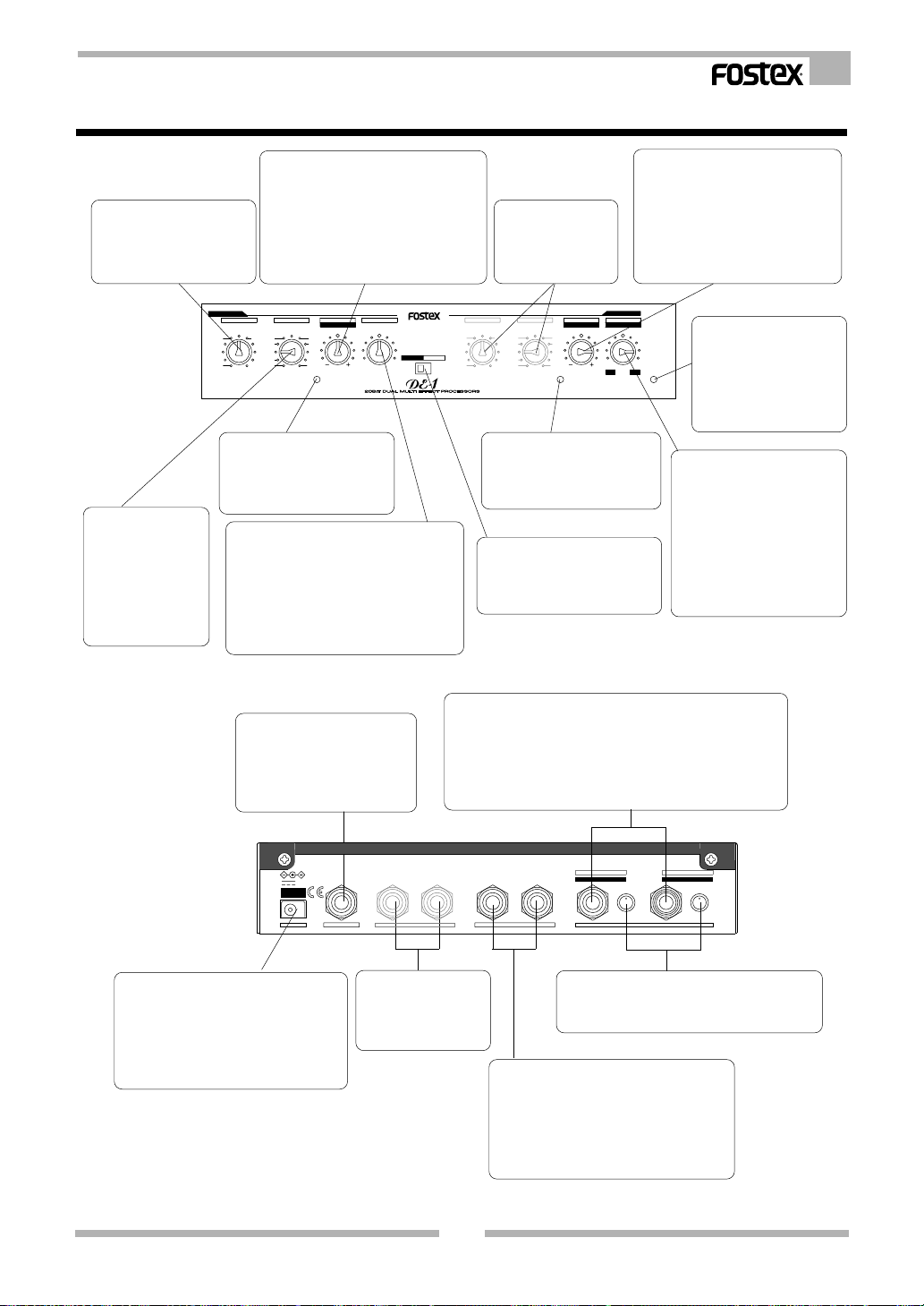
Functions
Here, we will discuss the switches and control knobs on the front panel and Input/Output jack
sockets on the rear panel. Note that some functions operate in a different ways depending on either
the Dual Mode or Single Mode you set up.
Functions of the Dual Mode
EFFECT 1 V ARIATION SW
Use this to choose the Variation
of the Effect Type for Effect 1.
There are 11 variations available
on each Effect T ype.
EFFECT 1 ADJUST knob
This control knob adjusts the
EFFECT 1 TYPE SW
Use this to choose the
Effect T ype for Effect 1.
There are 11 types
available.
EFFECT 1
VOCAL
PLATE MISC
ROOM
S.HALL
L.HALL
effect parameters of Effect 1.
The center position is the default
setting. If you turn it to the left,
the parameter will decrease.
Similarly, if you turn it to the right,
the parameter will increase.
VARIATION
TYPE
DLY+REV
DELAY
5
CHO
3
PITCH
2410
FLANGE
11
6
7
8
9
1
PEAK
PEAK LED
This will illuminate
when the Effect 1
Input signal reaches
6dB below the
distortion level.
EFFECT 1 MIX knob
Use this to adjust the mixing balance of the Dry
sound and Effect sound for the signal at the
OUTPUT 1 jack sockets;
on the Left Max. : DRY 100%, EFF 0%
in the Center : DRY 50%, EFF 50%
on the Right Max. : DRY 0%, EFF 100%
EFFECT 2 TYPE SW
Use this to choose the Effect T ype for
Effect 2. There are 1 1 types available.
EFFECT 2 V ARIATION SW
Use this to choose the Variation
of the Effect Type for Effect 2.
There are 11 variations
available on each Effect T ype.
ADJUST
MIX
PARAM.1
DRY+EFF DRY+EFF
DRY
EFF
MODE SW
Use this to choose
the operation mode
either Dual Mode or
Single Mode.
MODE
SINGLE DUAL
VOCAL
PLATE
ROOM
S.HALL
L.HALL
PEAK LED
This will illuminate
when the Effect 2
Input signal reaches
6dB below the
TYPE
DLY+REV
FLANGE
DELAY
MISC
CHO
PITCH
VARIATION
6
5
4108
3
2
1
distortion level.
EFFECT 2 ADJUST knob
This control knob adjusts the
effect parameters of Effect 2.
The center position is the
default setting. If you turn it
to the left, the parameter will
decrease. Similarly, if you
turn it to the right, the
parameter will increase.
POWER LED
EFFECT 2
MIX
ADJUST
PARAM.3
PARAM.2
7
9
1
1
DRY
EFF
_
+
PEAK
POWER
This illuminates when the
Power is ON. Also, this will
blink when the Effect
Mute is set to ON via the
Foot SW.
EFFECT 2 MIX knob
Use this to adjust the mixing balance of the
Dry sound and Effect sound for the signal at
the OUTPUT 2 jack sockets;
on the Left Max. : DRY 100%, EFF 0%
in the Center : DRY 50%, EFF 50%
on the Right Max. : DRY 0%, EFF 100%
Foot SW socket
Connect a Foot SW, such as the
Fostex Model 8051, to control the
Effect Mute ON/ OFF .
9V
AD-9B
ONLY
DC INLET socket
T o connect the standard accessory
AC adaptor to power up the DE-1.
As the unit does not have a power
switch, switching the power ON is
done by connecting the AC adaptor .
OUTPUT 1 jack sockets
These are the output terminals used to send a
processed audio signal via Effect 1 in stereo (L,
R). If you want to obtain a mono audio signal, use
only the OUTPUT L (MONO) jack socket.
EFF MUTE
FOOT SW
L (MONO)R
OUTPUT 2
R
L (MONO)
OUTPUT 1
OUTPUT 2 jack sockets
These are the output terminals used to
send a processed audio signal via Effect
2 in stereo (L, R). If you want to obtain a
mono audio signal, use only the
OUTPUT L (MONO) jack socket.
14
INPUT 1 (1 & 2) jack socket
This is the input terminal used to connect the
audio source for Effect 1. If you want to feed
the same audio signal to both Effect 1 and
Effect 2 at once, only use this socket without
connecting anything into the INPUT 2 jack
socket.
2
R
1 (1&2)
DUAL MODE
SINGLE MODE
L (MONO)
MAXMIN MIN MAX
INPUTINPUTDC IN
INPUT LEVEL knobs
These volume knobs
control the input level of
INPUT 1 and INPUT 2.
INPUT 2 jack socket
This is the input terminal used to connect the audio
source for Effect 2.
Page 15
Functions of the Single Mode
DE-1 Owner’s Manual
TYPE SW
Use this to choose the Effect
Type on the Single Mode.
There are 11 types available.
EFFECT 1
VOCAL
PLATE MISC
ROOM
S.HALL
L.HALL
VARIATION SW
Use this to choose
the Variation of the
Effect Type. There
are 11 variations
available on each
Effect Type.
PARAM. 1 knob
This control knob adjusts the Effect
Parameter 1. The center position is the
default setting. If you turn it to the left,
the parameter will decrease. Similarly,
if you turn it to the right, the parameter
will increase.
VARIATION
ADJUST
TYPE
DLY+REV
DELAY
5
CHO
3
PITCH
2410
FLANGE
11
6
7
8
9
1
PEAK
MIX
PARAM.1
DRY+EFF DRY+EFF
MODE
SINGLE DUAL
DRY
EFF
PEAK LED (L channel)
This will illuminate when the
Input signal reaches 6dB
below the distortion level.
MIX knob
Use this to adjust the mixing balance of
the Dry sound and Effect sound for the
signal from the OUTPUT L, R jack sockets;
on the Left Max. : DRY 100%, EFF 0%
in the Center : DRY 50%, EFF 50%
on the Right Max. : DRY 0%, EFF 100%
These knobs have
no functions in the
Single Mode
operation.
ADJUST
VARIATION
VOCAL
PLATE
ROOM
S.HALL
L.HALL
TYPE
DLY+REV
DELAY
FLANGE
MISC
CHO
PITCH
5
4108
3
2
1
PARAM.2
6
7
9
1
1
PEAK
PEAK LED (R channel)
This will illuminate when the
Input signal reaches 6dB below
the distortion level.
MODE SW
Use this to choose the operation
mode either the Dual Mode or
Single Mode.
PARAM. 2 knob
This control knob adjusts the Effect
Parameter 2. The center position is
the default setting. If you turn it to
the left, the parameter will decrease.
Similarly, if you turn it to the right,
the parameter will increase.
EFFECT 2
MIX
PARAM.3
POWER LED
This illuminates when the
DRY
EFF
_
+
POWER
Power is ON. Also, this will
blink when the Effect Mute
is set to ON via the Foot
SW.
PARAM. 3 knob
This control knob adjusts the
Effect Parameter 3. The
center position is the default
setting. If you turn it to the left,
the parameter will decrease.
Similarly, if you turn it to the
right, the parameter will
increase.
Foot SW socket
Connect a Foot SW, such as
the Fostex Model 8051, to
control the Effect Mute ON/
OFF.
9V
AD-9B
ONLY
DC INLET socket
T o connect the standard accessory AC
adaptor to power up the DE-1. As the
unit does not have a power switch,
switching the power ON is done by
connecting the AC adaptor .
EFF MUTE
FOOT SW
OUTPUT 2
These jack sockets
have no functions in
the Single Mode
operation.
INPUT L (MONO), R jack sockets
These are the input terminals used to connect the two
channel audio source for the Effect. If you want to feed the
same audio signal to both L channel and R channel at once,
only use the INPUT L (MONO) socket without connecting
anything into the INPUT R jack socket.
L (MONO)R
R
L (MONO)
OUTPUT 1
2
R
1 (1&2)
DUAL MODE
SINGLE MODE
L (MONO)
MAXMIN MIN MAX
INPUTDC IN
INPUT LEVEL knobs
These volume knobs control the input level of
INPUT 1 and INPUT 2.
OUTPUT L (MONO), R jack sockets
These are the output terminals used to send
a processed audio signal via the Effect in
stereo (L, R). If you want to obtain a mono
audio signal (L+R), use only the OUTPUT
L (MONO) jack socket.
15
Page 16
DE-1 Owner’s Manual
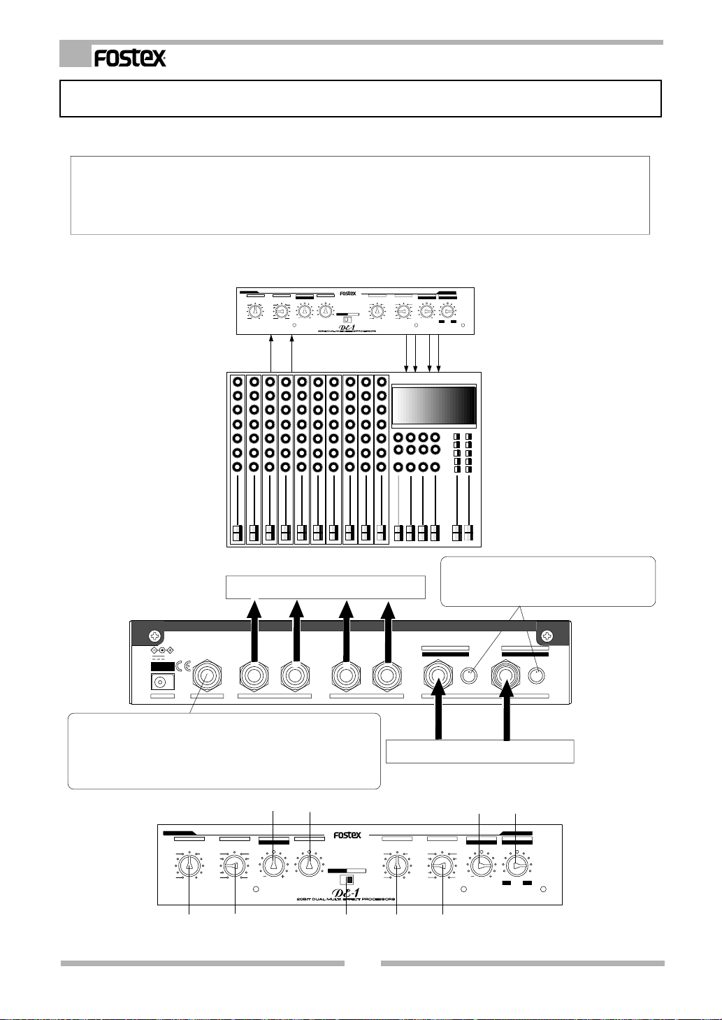
How to use the Dual Mode
Here, we discuss the practical operation of the Dual Mode. The Dual Mode has the features listed
below.
<Outstanding features of the Dual Mode>
1. You can use it as a two channel Effect Processor.
2. It provides one mono Input and stereo Outputs on each channel.
3. It has an independent PARAMETER ADJUST knob on each channel. With these, you can alter the
parameter setting in more detail on top of the typical preset designed for each Effect.
As an example of using the "DUAL MODE", connect the DE-1 between the AUX SEND and RETURN terminals of an
external mixing console. (In order to indicate the DE-1 connections plainly, other cable connections are leftout
in the connection example below.)
EFFECT 1
TYPE
DLY+REV
VOCAL
PLATE MISC
ROOM
S.HALL
L.HALL
DELAY
5
CHO
3
PITCH
2410
FLANGE
11
VARIATION
ADJUST
MIX
PARAM.1
DRY+EFF DRY+EFF
6
7
8
9
1
DRY
PEAK
VOCAL
PLATE
ROOM
MODE
SINGLE DUAL
S.HALL
L.HALL
EFF
TYPE
DLY+REV
DELAY
5
MISC
4108
CHO
3
PITCH
2
FLANGE
1
PARAM.3
PARAM.2
6
7
9
1
1
DRY
EFF
_
+
PEAK
POWER
EFFECT 2
MIX
ADJUST
VARIATION
AUX SEND 1
AUX SEND 2
For the audio mixer AUX Return terminals
R
OUTPUT 1
AD-9B
ONLY
EFF MUTE
9V
FOOT SW
L (MONO)R
OUTPUT 2
<Point>: Connect the Foot SW into the jack to remotely control the
Effect Mute ON/OFF. The POWER LED on the front panel will flash
when the Effect Mute in ON. The DE-1 will only mute the Effect sound.
The original source sound (Dry sound) will stay active even though the
Effect Mute is set to ON.
AUX RTN 1
AUX RTN 2
<Point>: Adjust the incoming signal level from
the mixer. See the Caution on the next page for
how to adjust the Input Level.
2
L (MONO)
DUAL MODE
SINGLE MODE
R
MAXMIN MIN MAX
INPUTINPUTDC IN
For the audio mixer AUX Send terminals
1 (1&2)
L (MONO)
EFFECT 1
TYPE
DLY+REV
DELAY
VOCAL
PLATE MISC
ROOM
S.HALL
FLANGE
L.HALL
VARIATION
6
5
CHO
3
PITCH
2410
11
4
5
ADJUST
MIX
PARAM.1
7
8
9
1
PEAK
DRY+EFF DRY+EFF
MODE
SINGLE DUAL
DRY
EFF
132
VOCAL
PLATE
ROOM
S.HALL
L.HALL
TYPE
DLY+REV
2
DELAY
FLANGE
5
MISC
4
CHO
3
PITCH
2
1
VARIATION
3
6
7
8
9
10
1
1
PEAK
4 5
ADJUST
PARAM.2
DRY
_
EFFECT 2
MIX
PARAM.3
EFF
+
POWER
16
Page 17
DE-1 Owner’s Manual
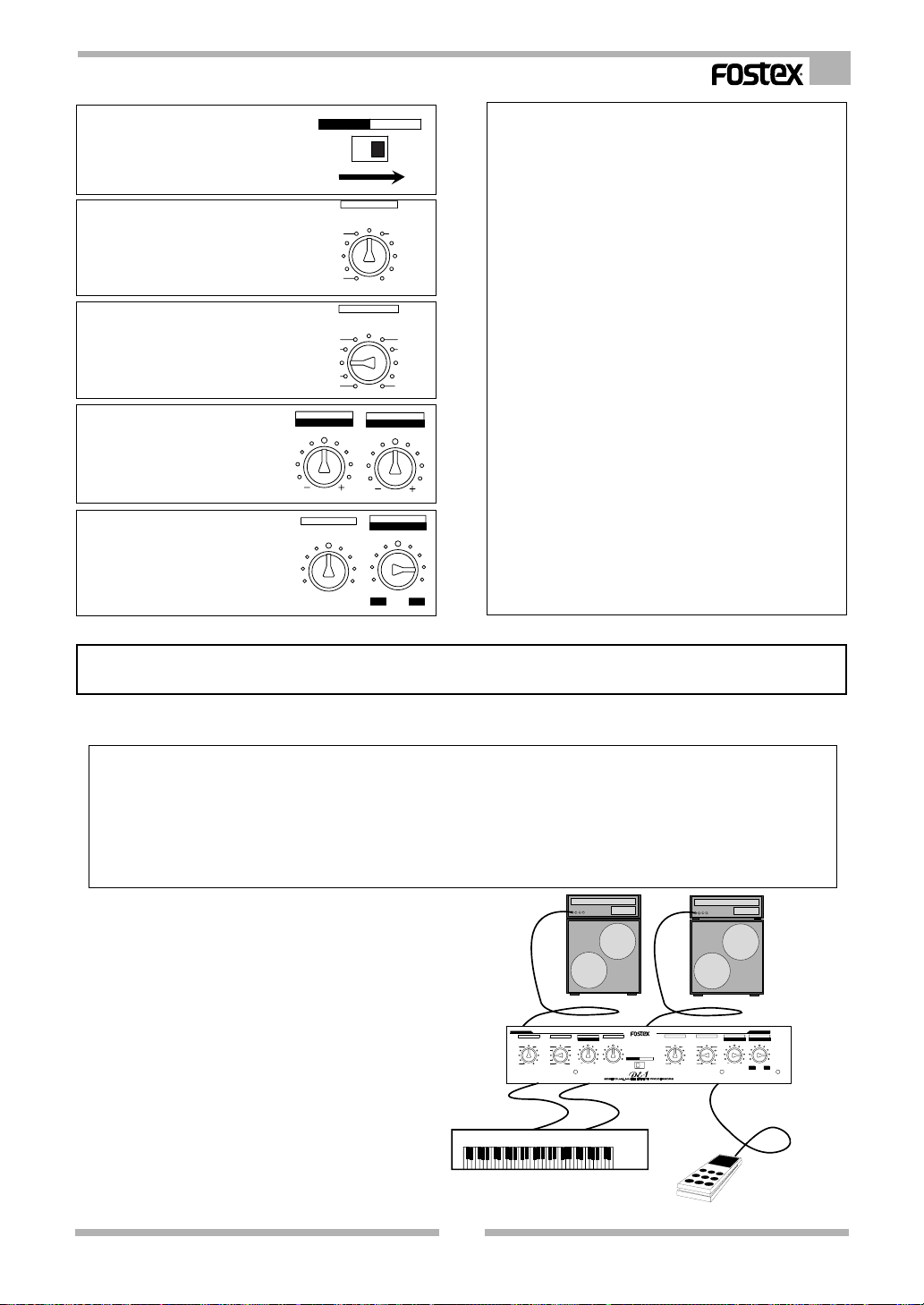
Select the “DUAL” on the
1
MODE SW.
Choose the Effect Type you
2
want to set for the Effect 1 and
Effect 2. See page 5 for the
variety of Effect T ypes.
Set the variation on the Effect
3
Type that you have chosen.
Adjust the parameters for
4
Effect 1 and Effect 2.
Adjust the mixing balance of
5
the Dry sound and Effect sound
to get the ratio you require from
the OUTPUT 1 and OUTPUT
2 jack sockets.
MODE
SINGLE DUAL
TYPE
DLY+REV
VOCAL
PLATE MISC
ROOM
S.HALL
L.HALL
VARIATION
6
5
4
3
2
11
ADJUST
PARAM.1
DRY+EFF
DRY
MIX
ADJUST
PARAM.2
PARAM.3
DRY+EFF
DRY
EFF
_
DELAY
CHO
PITCH
FLANGE
7
8
9
10
1
MIX
<Caution on Effect Processing>
The PEAK LED indicator on the front panel is designed so
that it will illuminate when the Input signal reaches 6dB below
the distortion level. First, adjust the Input level using the
control knob and watch the LED indicator. The best level
setting makes the PEAK LED illuminate occasionally. In the
case of the sound being distorted in the internal DSP, in
spite of no indications on the PEAK LED, this is due to the
rise of the entire signal level due to a variety of Effect sounds
being used. If this happens, reduce the Input level with the
control knob so that the Output sound is not distorted.
<Caution on changing SW position>
The Output signal will disappear momentarily when you
change the position of the MODE SW, EFFECT TYPE SW
and VARIATION SW. This is not a fault. It is due to the DE1 resetting its internal DSP .
<Caution when using the ADJUST knob and MIX knob>
Some clicking noises may be heard when you control the
ADJUST knob and MIX knob, with certain types and sounds
of the Effect.
The ADJUST knob may not give you functions even if you
try to increase the parameter when the default setting is
already at the maximum. Similarly, you cannot decrease it
further if the default parameter setting is already at the
EFF
+
minimum position.
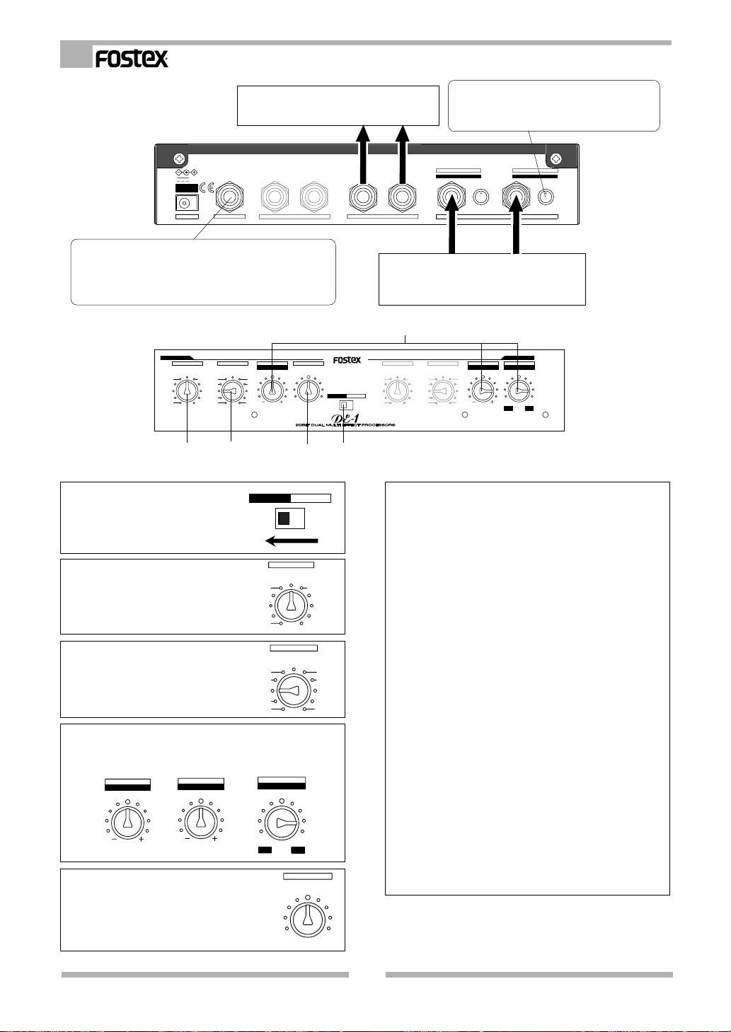
How to use the Single Mode
Here, we discuss the practical operation of the Single Mode. The Single Mode has the features listed
below.
[Outstanding features of the Single Mode]
1. You can use it as a high quality single channel Effect Processor.
2. It provides stereo Inputs and Outputs.
3. It has three ADJUST knobs as PARAM. 1~3. With these, you can alter three individual parameter settings
in more detail, on top of the typical presets designed for each Effect.
4. It offers a higher density reverb than the Dual Mode.
5. The independent channel algorithm offers completely separate Output signals for each channel (L,R).
This is an example of the “Single Mode” used
in a live performance. Connect the stereo output
of the Keyboard directly into the DE-1 Input
jack sockets. Connect the Effect Output of the
DE-1 into the two separate PA speakers. Also
you can operate the Effect Mute ON/OFF
remotely via a Foot SW such as Fostex Model
8051.
EFFECT 1
TYPE
DLY+REV
VOCAL
PLATE MISC
ROOM
S.HALL
L.HALL
DELAY
5
CHO
3
PITCH
2410
FLANGE
11
VARIATION
ADJUST
MIX
PARAM.1
DRY+EFF DRY+EFF
6
7
8
9
1
PEAK
MODE
SINGLE DUAL
DRY
EFF
VARIATION
TYPE
DLY+REV
DELAY
VOCAL
5
MISC
PLATE
4108
ROOM
CHO
3
PITCH
S.HALL
2
FLANGE
L.HALL
1
EFFECT 2
MIX
ADJUST
PARAM.3
PARAM.2
6
7
9
1
1
DRY
EFF
_
+
PEAK
POWER
17
Page 18
DE-1 Owner’s Manual
To the two separate PA speakers Input
terminal
EFF MUTE
9V
AD-9B
ONLY
FOOT SW
OUTPUT 2
<Point>: Connect a Foot SW into the jack to control the
Effect Mute ON/OFF remotely . The POWER LED on the
front panel will flash when the Effect Mute in ON. This
operation is the same as in the Dual Mode.
EFFECT 1
DLY+REV
VOCAL
PLATE MISC
ROOM
S.HALL
L.HALL
TYPE
DELAY
CHO
PITCH
FLANGE
VARIATION
5
3
2410
11
ADJUST
PARAM.1
6
7
8
9
1
PEAK
2
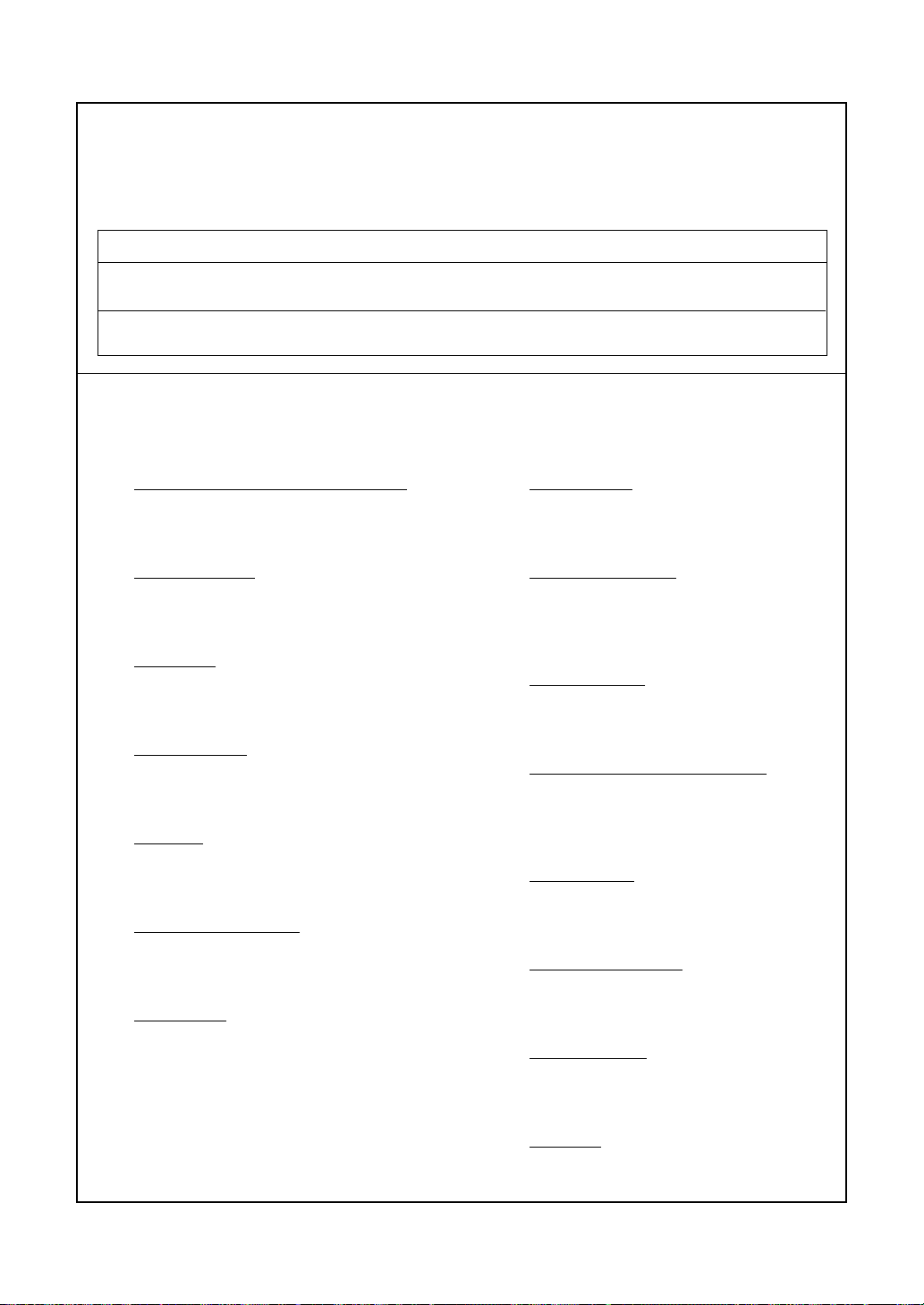
Select the “SINGLE” on the
1
MODE SW.
Choose the Effect Type you
2
want to set. See page 5 for
the variety of the Effect T ypes.
Set the variation on the Effect
3
Type that you have chosen.
Adjust the parameters (PARAM. 1~3) for the Ef fect. In
4
the Single Mode, use these three control knobs as
seen in the drawing below.
ADJUST
PARAM.1
Adjust the mixing balance of the Dry
5
sound and Effect sound to get the ratio
ADJUST
PARAM.2
you require from the OUTPUT L and R
jack sockets.
MODE
SINGLE DUAL
TYPE
DLY+REV
VOCAL
PLATE MISC
ROOM
S.HALL
L.HALL
VARIATION
5
4
3
2
11
MIX
PARAM.3
DRY+EFF
DRY
_
DRY
<Point>: Adjust the incoming signal level from
the musical instruments. See the Caution below
for how to adjust the Input Level.
2
L (MONO)R
R
L (MONO)
OUTPUT 1
DUAL MODE
SINGLE MODE
R
MAXMIN MIN MAX
INPUTDC IN
T o the musical instruments (Keyboard)
If it is mono source, connect it to the L (MONO)
jack socket.
4
MIX
DRY+EFF DRY+EFF
MODE
SINGLE DUAL
DRY
EFF
13
5
VOCAL
PLATE
ROOM
S.HALL
L.HALL
DLY+REV
VARIATION
TYPE
DELAY
5
MISC
4
CHO
3
PITCH
2
FLANGE
1
<Caution on Effect Processing>
The PEAK LED indicator on the front panel is designed so
that it will illuminate when the Input signal reaches 6dB below
the distortion level.
First, adjust the Input level using the control knob and watch
the LED indicator. The best level setting makes the PEAK
DELAY
CHO
PITCH
FLANGE
LED illuminate occasionally.
In the case of the sound being distorted in the internal DSP ,
in spite of no indications on the PEAK LED, this is due to
the rise of the entire signal level due to a variety of Effect
sounds being used. If this happens, reduce the Input level
6
7
8
9
10
1
with the control knob so that the Output sound is not distorted.
<Caution on changing SW position>
The Output signal will disappear momentarily when you
change the position of the MODE SW, EFFECT TYPE SW
and VARIATION SW. This is not a fault. It is due to the DE1 resetting its internal DSP .
<Caution when using the ADJUST knob and MIX knob>
Some clicking noises may be heard when you control the
ADJUST knob and MIX knob, with certain types and sounds
of the Effect.
The ADJUST knob may not give you functions even if you
EFF
+
try to increase the parameter when the default setting is
already at the maximum. Similarly, you cannot decrease it
further if the default parameter setting is already at the
MIX
DRY+EFF
EFF
minimum position.
ADJUST
PARAM.2
6
7
8
9
10
1
1
PEAK
DRY
_
EFFECT 2
MIX
PARAM.3
1 (1&2)
L (MONO)
EFF
+
POWER
18
Page 19

Block Diagram
DE-1 Owner’s Manual
Dual Mode
INPUT 1 (1&2)
INPUT 2
Single Mode
INPUT L (MONO)
INPUT R
INPUT
INPUT
INPUT
INPUT
A/D
A/D
A/D
A/D
TYPE VARIATION
PROCESSOR
TYPE VARIATION
PROCESSOR
PROCESSOR
ADJUST
PARAM.1
EFFECT
ADJUST
EFFECT
ADJUST
TYPE
EFFECT
ADJUST
PARAM.2
VARIATION
ADJUST
PARAM.3
DRY
EFF
EFF
DRY
DRY
EFF
EFF
DRY
DRY
EFF
EFF
DRY
MUTE DATA
D/A
MIX
D/A
D/A
MIX
D/A
D/A
MIX
D/A
D/A
L (MONO)
OUTPUT 1
R
L (MONO)
OUTPUT 2
R
L (MONO)
OUTPUT 1
R
L (MONO)
<INPUT x 2>
Connector: ø6mm phone jack/unbalanced
Input Impedance: 20k or more
Input Level: -10dBV
<OUTPUT x 4>
Connector: ø6mm phone jack/unbalanced
Load Impedance: 10k or more
Output Level: -10dBV
<FOOT SWITCH>
Connector: ø6mm phone jack (optional Model 8051)
MUTE DATA
Specifications
<OTHERS>
Frequency Response: 20Hz ~ 15kHz (TYPICAL)
Dynamic Range: 92dB (TYPICAL)
AD/DA converter: 20bit
T otal Harmonic Distortion: 0.01% (TYPICAL)
Sampling Frequency: 32kHz
<GENERAL>
Dimensions: 220 (W)x 43 (H) x 187 (D) mm
Weight: Approx. 1.0kg
Power Supply: DC 9V (the Center Positive), AD-9B
* Specifications and appearance are subjects to change without
notice for product improvement.
19
D/A
OUTPUT 2
R
Page 20
Declaration of EC Directive
This equipment is compatible with the EMC Directive (89/336/EEC) - Directive on approximation of member
nation's ordinance concerning the electromagnetic compatibility and with the Low Voltage Directive (73/23/
EEC) - Directive on approximation of member nation's ordinance concerning electric equipment designed to be
used within the specified voltage range.
The Affect of Immunity on This Equipment
The affect of the European specification EN50082-1 (coexistence of electromagnetic waves - common immunity specification)
on this equipment are as shown below.
* In the electrical fast transient / burst requirements, radiated electromagnetic field requirements and static electricity discharging environment, this could be affected by generation of noise in some cases.
FOSTEX DISTRIBUTORS LIST IN EUROPE
* Including non - EU countries. * underlined: contracted distributors (as of April, 1999)
<AUSTRIA>
NAME: ATEC Audio-u. Videogeraete VertriebsgesmbH.
ADD: Im Winkel 5, A-2325 Velm, Austria
TEL: (+43) 2234-74004, FAX: (+43) 2234-74074
<BELGIUM>
NAME: Sound Industries NV
ADD: Bijvennestraat 1A, B3500 Hasselt, Belgium
TEL: (+32) 11-232355, FAX: (+32) 11-232172
<DENMARK>
NAME: SC Sound ApS
ADD: Malervej 2, DK-2630 Taastrup, Denmark
TEL: (+45) 4399-8877, FAX: (+45) 4399-8077
<FINLAND>
NAME: Noretron Oy Audio
ADD: Tonttumuorinkuja 4, FIN-02200 Espoo, Finland
TEL: (+358) 9-5259330, FAX: (+358) 9-52593352
<FRANCE>
NAME: Musikengro
ADD: ZAC de Folliouses, B. P. 609, 01706 Les Echets, France
TEL: (+33) 472 26 27 00, FAX: (+33) 472 26 27 01
<GERMANY>
NAME: Studiosound & Music GmbH
ADD: Industriestrasse 20, D-35041 Marburg, F. R. Germany
TEL: (+49) 6421-92510, FAX: (+49) 6421-925119
<GREECE>
NAME: Bon Studio S. A.
ADD: 6 Zaimi Street, Exarchia, 106.83 Athens, Greece
TEL: (+30) 1-3809605-8, 3302059, FAX: (+30) 1-3845755
<ICELAND>
NAME: I. D. elrf. electronic Ltd.
ADD: Armula 38 108 Reykjavik, Iceland
TEL: (+354) 588 5010, FAX: (+354) 588 5011
<ITALY>
NAME: Recoton Italia Srl.
ADD:V. 1 Maggio, N 18, 40050 Quarto Inferiore, (BO) Italy
TEL: (+39) 051-768576, FAX: (+39) 051-768336
<THE NETHERLANDS>
NAME: IEMKE ROOS AUDIO B. V.
ADD: Kuiperbergweg 20, 1101 AG Amsterdam, The Netherlands
TEL: (+31) 20-697-2121, FAX: (+31) 20-697-4201
<NORWAY>
NAME: Siv. Ing. Benum A/S
ADD: P. O. Box 145 Vinderen, 0319 Oslo 3, Norway
TEL: (+47) 22-139900, FAX: (+47) 22-148259
<PORTUGAL>
NAME: Caius - Tecnologias Audio e Musica, Lda.
ADD: Rua de Santa Catarina, 131 4000 Porto, Portugal
TEL: (+351) 2-2086009/2001394, FAX: (+351) 2-2054760/
2087488
<SPAIN>
NAME: Multitracker. S. A.
ADD: C/Garcilaso No. 9, Madrid 28010, Spain
TEL: (+34) 91-4470700, 91-4470898, FAX: (+34) 91-5930716
<SWEDEN>
NAME: Professional Television AB
ADD: Gelbgjutarevagen 4, S-171 48 Solna, Sweden
TEL: (+46) 8-59798000, FAX: (+46) 8-59798001
<SWITZERLAND>
NAME: Audio Bauer Pro AG
ADD: Bernerstrasse-Nord 182, CH-8064 Zurich, Switzerland
TEL: (+41) 1-4323230, FAX: (+41) 1-4326558
<UK>
NAME: SCV London
ADD: 3A 6-24 Southgate Road, London N1 3JJ, England, UK
TEL: (+44) 171-923-1892, FAX: (+44) 171-241-3644
 Loading...