

Page 1
Quick Start Guide
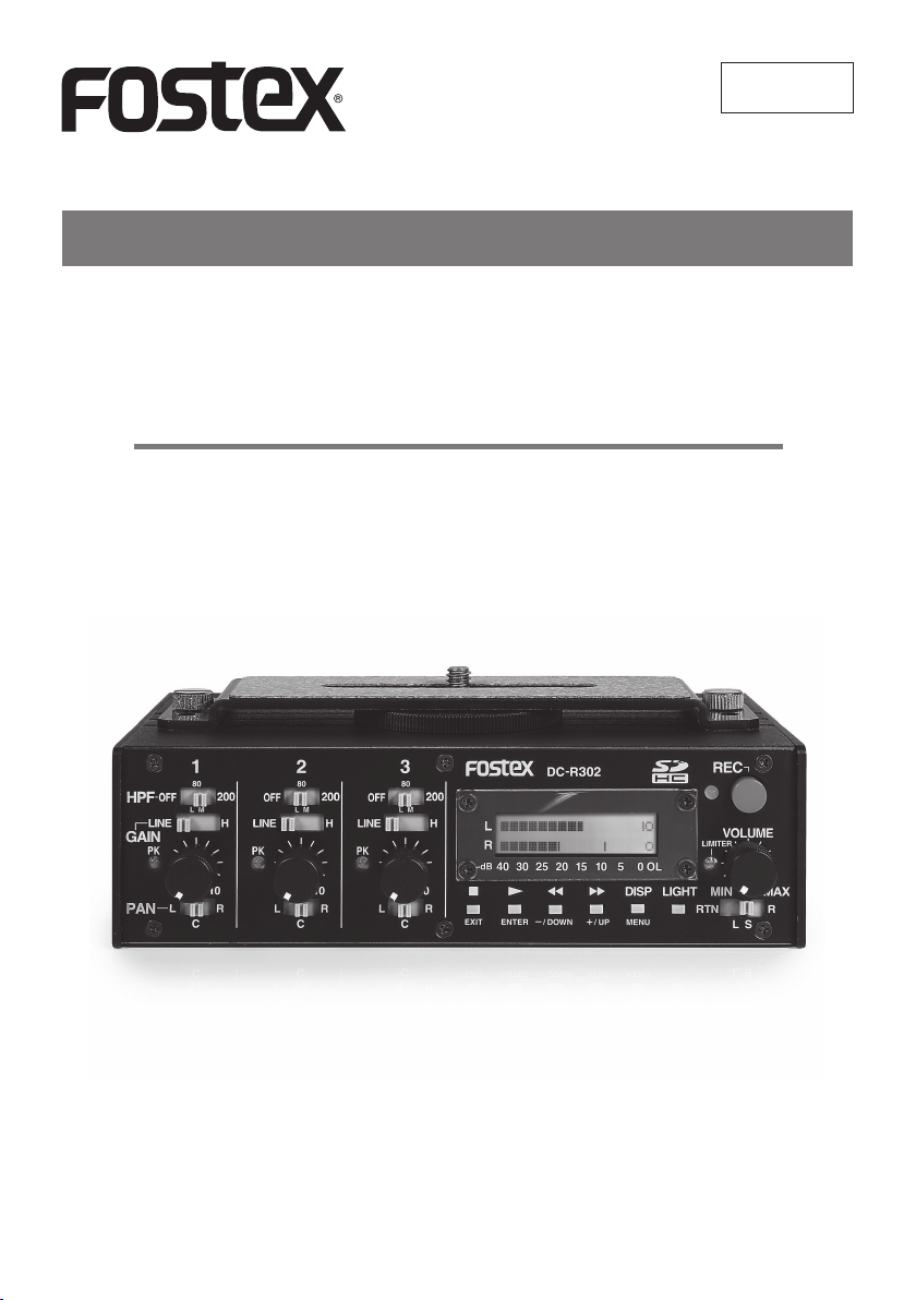
DC-R302
Portable recorder
8289682100
(564922)
This manual provides the basics of the DC-R302. Read this
before you use the unit for the rst time.
For the more detailed information, see the “Owner’s manual
(details)” that can be downloaded from the Fostex website
(www.fostex.com).
Page 2

CAUTION
RISK OF ELECTRIC SHOCK
DO NOT OPEN
CAUTION: TO REDUCE THE RISK OF ELECTRIC SHOCK,
DO NOT REMOVE COVER (OR BACK).
NO USER - SERVICEABLE PARTS INSIDE.
REFER SERVICING TO QUALIFIED SERVICE PERSONNEL.
“WARNING”
“TO REDUCE THE RISK OF FIRE OR ELECTRIC
SHOCK, DO NOT EXPOSE THIS APPLIANCE TO
RAIN OR MOISTURE.”
SAFETY INSTRUCTIONS
The lightning ash with arrowhead symbol, within an equilateral triangle, is intended to alert the user to the presence
of uninsulated “dangerous voltage” within
the product’s enclosure that may be of
sufficient magnitude to constitute a risk
of electric shock to persons.
The exclamation point within an equilateral triangle is intended to alert the user to
the presence of important operating and
maintenance (servicing) instructions in the
literature accompanying the appliance.
1) Read these instructions.
2) Keep these instructions.
3) Heed all warnings.
4) Follow all instructions.
5) Do not use this apparatus near water.
6) Clean only with dry cloth.
7) Do not block any ventilation openings.
Install in accordance with the manufacturer's
instructions.
8) Do not install near any heat sources such as
radiators, heat registers, stoves, or other apparatus (including ampliers) that produce heat.
9) Do not defeat the safety purpose of the polarized or grounding-type plug. A polarized plug
has two blades with one wider than the other. A
grounding type plug has two blades and a third
grounding prong. The wide blade or the third
prong are provided for your safety. If the provided plug does not t into your outlet, consult
an electrician for replacement of the obsolete
outlet.
10) Protect the power cord from being walked on
or pinched particularly at plugs, convenience
receptacles, and the point where they exit from
the apparatus.
11) Only use attachments/accessories specied by
the manufacturer.
12) Use only with the cart, stand, tripod, bracket,
or table specied by the manufacturer, or sold
with the apparatus. When a cart is used, use
caution when moving the cart/apparatus combination to avoid injury from tip-over.
13) Unplug this apparatus during lightning storms
or when unused for long periods of time.
14) Refer all servicing to qualied service personnel. Servicing is required when the apparatus
has been damaged in any way, such as powersup pl y c ord or plug is damaged, liqu id has
been spilled or objects have fallen into the apparatus, the apparatus has been exposed to
rain or moisture, does not operate normally, or
has been dropped.
15) Excessive sound pressure from earphones and
headphones can cause hearing loss.
E-2
Page 3

FCC (U.S.A.) & ICES-003 (Canada) INFORMATION
1. IMPORTANT NOTICE
This product, when installed as indicated in the
instructions contained in this manual, meets FCC
and ICES-003 requirements. Changes or modications not expressly approved by Fostex Company
for compliance could void the user’ s authority to
ope rate the equi pment. DO NOT MODIFY THIS
PRODUCT.
2. IMPORTANT
In order to comply with FCC and ICES-003 requirements, use high quality shielded cables for connection to accessories and / or another products. If any
cables are supplied with this product, they MUST
be used. Follow all installation instructions. Failure
to do so could void your FCC / ICES-003 authorization to use this product in the USA / Canada.
3. NOTE
This equipment has been tested and found to comply with the limits for a Class A digital device, pursuant to Part 15 of the FCC Rules. These limits are
designed to provide reasonable protection against
harmful interference when the equipment is operated in a commercial environment. This equipment
generates, uses and can radiate radio frequency
energy and, if not installed and used in accordance
with the i nstruction manual, may cause harmful
interference to radio communications. Operation
of this equipment in a residential area is likely to
cause harmful interference in which case the user
will be required to correct the interference at his
own expense.
4. Compliance with Part 15 of FCC Rules and Canadian ICES-003.
Th is d evi c e c o mpl ies wit h Par t 1 5 of the FCC
Rules. Operation is subject to the following two
conditions: (1) This device may not cause harmful
interference, and (2) this device must accept any
interference received, including interference that
many cause undesired operation.
This Class A digital apparatus complies with Canadian ICES-003.
Cet appareil numérique de la classe A est conforme
à la norme NMB-003 du Canada.
Introduction
Thank you very much for purchasing the Fostex
DC-R302 portable recorder.
The DC-R302 is a portable stereo recorder with
3-channel audio mixer ideal for DSLR (Digital Single
Lens Reex) video recording. You can record audio
to an SD card while feeding it to a DSLR camera.
A DSLR camera can be mounted on the top of the
unit.
Supplied accessories
The following accessories are supplied with the
DC-R302.
•
Bracket for camera mounting x 1
•
Quick start guide (this manual) x 1
After purchasing the DC-R302, check that all the
accessories are included in the package.
Table of contents
Safety instructions .........................................E-2
Introduction ...................................................E-3
Table of contents ........................................... E-3
Features and controls
Front panel .............................................. E-4
Left side panel .........................................E-5
Right side panel ......................................E-6
Top panel .................................................E-7
Bottom panel...........................................E-7
Basic signal ow ............................................ E-7
Recording tutorial
Preparations ............................................E-8
Recording ................................................ E-8
Mounting a DSLR camera to the unit ............ E-8
Using the menu .............................................E-9
Menu operation .......................................E-9
Declaration of EC Directive .........................E-10
Fostex distributors list in Europe ................. E-10
E-3
Page 4

Features and controls
Front panel
❷ ❼ ❽ ❾
❸ ❹ ❻❺❶
1 2 3
80
200
OFF
HPF
GAIN
PAN
LINE
PK
L R
C
ML
100
80
OFF
LINE
H
PK
L R
C
200
OFF
ML
H
LINE
PK
100 100
R
80
L
C
❿ ⓫ ⓬ ⓭
[PK] indicators (1 through 3)
❶
Whe n a n i nput signal i s t oo loud, this indi ca tor
lights in red.
If the indicator lights fre qu en tl y, set the [GAIN]
switch to a more left position.
[GAIN] switches (1 through 3)
❷
Each switch should be set appropriately according
to the microphone sensitivity or the volume of an
audio source.
If the [PK] indicator lights in red frequently, select a
more left position.
[HPF] switches(1 through 3)
❸
When an input signal from the [INPUT] connector
contains suppressing wind or other low frequency
noise, you can remove it by setting this switch to
“80” or “200”.
Level controls (1 through 3)
❹
Each level control controls the recording level of the
corresponding input signal.
You can check the recording level via the level meter on the display.
[PAN] switches (1 through 3)
❺
Each switch decides the signal’s left-right position
in stereo for recording. You can select from left (L),
center (C) or right (R).
LIMITER
REC
VOLUME
MAXMIN
RRTN
L
S
200
ML
H
L
R
-dB
40 30 25 20 15 10 5 0 OL
EXIT ENTER -/DOWN +/UP MENU
DC-R302
DISP LIGHT
⓮ ⓯ ⓰ ⓱
Display
❻
Shows the level meters or other various information.
In the menu mode, the display shows a menu item.
[LIMITER] indicator
❼
When the recording signal is too loud, the internal
limiter automatically reduces the volume to prevent
distortion.
This indicator lights in yellow when the limiter is active.
If the indicator lights frequently, reduce the level
control.
Status indicator
❽
Lights in red during recording.
Lights in green during playback.
[REC] key
❾
Starts or stops recording.
While the recorder is stopped, pressing this key
starts recording.
During recording, pressing this key stops recording.
] ([EXIT]) key
[
❿
■
Stops playback.
In the menu mode, it acts as the [EXIT] key.
E-4
Page 5

Features and controls
▲
] ([ENTER]) key
[
⓫
Starts playback while the recorder is stopped.
In the menu mode, it acts as the [ENTER] key.
] ([-/DOWN]) key
[
⓬
▲
▲
When the recorder is stopped, pressing the key
briefly skips back to the beginning of the current
or previous file, while holding down the key fastrewinds the le.
During playback, pressing the key briey skips to
the beginning of the file, while holding down the
key executes backward cueing playback.
During recording, the key is disabled.
In the menu mode, the key is used for changing the
setting.
▲
▲
] ([+/UP]) key function:
[
⓭
When the recorder is stopped, pressing the key
briefly skips forward to the beginning of the next
le, while holding down the key fast-forwards the
le.
During playback, pressing the key briey skips to
the beginning of the next le, while holding down
the key executes forward cueing playback.
During recording, the key is disabled.
In the menu mode, the key is used for changing the
setting.
[DISP] ([MENU]) key
⓮
Pre ss in g t he key b ri ef ly chan ge s t he disp la ye d
item.
Pressing the key for more than two seconds enters
the menu mode. In the menu mode, pressing the
key changes the menu item.
[LIGHT] key
⓯
Pressing the key briey turns on the display backlight for two seconds and then turns off.
By pressing the key more than two seconds, the
display backlight keeps lighting until you press the
key more than two seconds again.
Left side panel
❷ ❸❶
INPUT-1 INPUT-2 INPUT-3
OFF P48 P48OFF P48OFF
MIC OUT
[INPUT] connectors (1 through 3)
❶
Used for connecting to microphones, etc.
You should set the [GAIN] switch appropriately according to the input source.
Phantom power switches (1 through 3)
❷
When connecting a condenser microphone requiring 48V phantom power to the [INPUT] connector,
“P48” should be selected.
<Note>:Do not connect or disconnect a microphone while this switch is set to “P48”. A large
click noise may be generated.
[MIC OUT] connector
❸
This connector allows sending the same signal as
recorder’s input signal to the microphone input of a
DSLR camera.
It a lso allows remot e reco rd start/stop of some
DSLR camera.
See “Owner’s manual (details)” for detail.
[VOLUME] control
⓰
Controls the headphone volume.
Monitor source selector
⓱
Selects the headphone monitor source from the followings.
RTN: the [RTN IN] signal
L: recorder’s left track
S: recorder’s left and right tracks in stereo
R: recorder’s right track
E-5
Page 6

Features and controls
❶ ❷❼❸ ❹
❻❺ ❽ ❾
Right side panel
HOLD
REMOTE USB
POWER
OUTPUT
PHONES RTN IN
[POWER] switch
❶
Used to turn the power on or off.
While the power is off, you can turn on the power
by sliding up and release the switch.
While the power is on, you can turn off the power
by sliding up and holding the switch for two seconds.
<Memo >: Du ri ng play ba ck or recordi ng , y ou
cannot turn off the power.
[REMOTE] connector
❷
By connecting a Panasonic (or equivalent) remote
shutter release to this connector, you can start or
stop recording using the remote shutter release.
LEFT RIGHT
DC-IN
9-24V
SD
[PHONES] connector
❺
Provided for connecting headphones for monitoring.
[OUTPUT] connectors (L and R)
❻
These connectors output the recorder’s output signals.
[RTN IN] connector
❼
Provided for connecting the stereo output of an external device.
You can monitor the signal received from this connector via headphones.
[SD-CARD] slot
❽
This slot is located inside the battery compartment
cover.
To set an SD card to the slot, hold an SD card with
the label side facing to the battery compartment,
and press the card into the slot until you hear a
click.
To remove an SD card, firmly press the card into
the slot and release it. The card should pop partially
out of the slot. Remove the card from the slot.
<Memo> :You can use the following SD card
types with the unit.
SD, SDHC, MiniSD, MiniSDHC,
MicroSD, MicroSDHC
* When you use a MiniSD or microSD card, use
the appropriate card adaptor.
* You cannot use an SDXC card.
[USB] connector
❸
By connecting to a personal computer using a USB
cable, you can transfer audio data, copy audio les,
etc. between the unit and a personal computer.
[DC-IN] connector
❹
Provided for connecting the optional AC adaptor
(AC12) or an external battery power supply to run
the unit.
When a plug is connected to this connector, the
internal battery power is disabled.
<Cauti on>:W hen you c onnect or disconnect
a plug to this connector, make sure that the
power is off.
Battery compartment
❾
To run the unit on battery power, set four AA batteries into this compartment. It is recommended to
use alkaline or rechargeable nickel hydride batteries.
To remove battery compartment, open the battery
compartment cover and pull up the ribbon attached
to the battery compartment.
E-6
Page 7

Limiter
GAIN
HPF
Level
OUTPUT
PAN
Features and controls
Top panel
❷❶
Sc rew hol es f o r mo unti n g br acke t fo r
❶
camera mounting
These screw holes are used for xing the supplied
bracket for camera mounting.
The bracket provides a screw for xing a camera.
Infrared LEDs
❷
These LEDs are used for controlling record start/
stop of a DSLR camera which supports infrared
remote.
Basic signal ow
The input signal from each of [INPUT] connectors 1
through 3 on the left side panel ows to the [GAIN]
switch, [HPF] switch and level control. Then the
signal is assigned to the left, right or both recording
tracks by the [PAN] switch. The assigned signals
are mixed and recorded to the recorder.
The recorder stereo output signals are output from
the [OUTPUT] connectors.
Bottom panel
❶
Tripod screw holes
❶
Used for mounting the unit on a camera tripod, etc.
<Memo>:Limiters are provided after the [GAIN]
switches as well as before the recorder inputs
to eliminate sound distortion caused by overload. The limiters work automatically depending
on audio levels.
INPUT-1 Limiter
Input
signal
INPUT-2
Input
signal
INPUT-3
Input
signal
switch
switch
control
switch
E-7
L
R
L
R
L
R
Recorder
LEFT
RIGHT
Page 8

Recording tutorial
Recording
The followin g show s how to reco rd high quality
audio to the recorder. In this example, two microphones are used and the unit runs on batteries.
Preparations
1. Insert four alkaline or rechargeable nickel hydride
AA batteries to the battery compartment on the
right side panel.
To remove battery compartment, open the bat-
tery compartment cover and pull up the ribbon
attached to the battery compartment.
2. Insert a new SD card to the [SD-CARD] slot.
The [SD-CARD] slot is located inside the battery
compartment cover.
To set an SD card to the slot, hold an SD card
with the label side facing to the battery compartment, and press the card into the slot until you
hear a click.
3. Connect two microphones to [INPUT] connectors
1 and 2 on the left side panel.
4. Connect headphones to the [PHONE] connector
on the right side panel.
Set the following switches and control for each input signal appropriately.
5. When you use a condenser microphone that requires phantom power, set the phantom power
switch above the [INPUT] connector to “P48”.
6. Set the [PAN] switch on th e f ro nt panel to L
(left), R (right) or C (center) depending on which
track(s) you want to record audio onto.
7. Set the [GAIN] switch and the level control on
the front panel appropriately depending on the
microphone sensitivity and audio source volume.
If the [PK] indicator lights in red frequently, set
the [GAIN] switch to a more left position. The
more right position of this switch provides higher
sensitivity.
If the “OL” of the leve l m eter o n t he displ ay
lights, turn the level control down (counterclockwise).
<Memo>:It is recommended to make settings
above while listening to the sound via headphones. You can control the headphone volume
using the [VOLUME] control on the front panel.
After all the preparations are made, you are now
ready for recording.
1. To start recording, press the [REC] key on the
front panel.
2. To stop recording, press the [REC] key again.
The recorder stops recording and closes the le.
Now an audio le (44.1 kHz/16-bit WAV le, by
default) is created on the SD card.
Playing back the recorded le
Now, let’s play back the recorded le and check the
result via headphones.
1. Press the [▲] key.
The recorder starts playback of the le.
After finishin g playback of the file, the re corder
stops.
▲
• By holding down the [
rewind or fast-forward the le.
• By pressing the [
back to the beginning of the le.
• Pressing the [
■
▲
] key briefly, you can skip
▲
▲
] key stops playback.
] or [
▲
▲
] key, you can
Mounting a DSLR camera to the unit
The following desc ri be s h ow to mount a DSLR
camera to the unit.
1. Fix the screws of the supplied bracket for camera mounting to the screw holes on the top panel
of the unit.
2. Fix the m o vab le screw o n t he c ent er o f t h e
bracket to the tripod screw hole on a DSLR camera.
Be sure to determine the appropriate position
before xing the screw.
E-8
Page 9

Using the menu
The menu allows you to make the various settings
of the unit, etc.
The follo wi ng chart shows t he list of the menu
items.
Menuitem
FS/BIT
TONEREC(S)
Description
SelectsFs/bit
Selects"Recordstarttone"
recordmode
TONEREC(E)
Selects"Recordendtone"
recordingmode
RECSTOPKEY
DEF.FILENAME
MAXFILENAME
AUTOCONTFILE
BATTERY
USB
IRREMOTE
SDFORMAT
RTC
RESET
VER
Selectskeyforrecordstop
Selects "default file name"
Selects maximum file size
"Auto continuous file" mode ON/OFF
Selectsbatterytype
SelectsUSBconnectionmode
Selectsinfra-redcontrolleddevice
FormatsSDcard
Adjustsinternalclock
Initializes menu item settings
Displayscurrentversion
Menu operation
1. Press the [MENU] key for more than two seconds
while the recorder is stopped.
The unit enters the menu mode and the display
shows the menu item that was shown last time.
2. Select the desired menu item by pressing the
[MENU] key.
Pressing the “MENU” key for 2 seconds while
any of the menu items is displayed, the order of
displaying the menu items will become reversed.
Pressing the “MENU” key again for 2 seconds
will make the menu items back to the original
displaying order.
3. If the menu item is for selecting an option, select
the desired option using the [-/DOWN] and [+/
UP] keys.
If the menu item is for execution, follow the in-
structions on the display.
Settingoptions
44/16,48/16,44/24,
Default
44/16
48/24,88/24,96/24
OFF,ON(0s),ON(0.5s),ON(1s),
OFF
ON(1.5s),ON(2s),ON(3s)
OFF,ON(0s),ON(0.5s),ON(1s),
OFF
ON(1.5s),ON(2s),ON(3s)
REC,REC&STOP,STOP
SCENE,DC-R_
2G,4G
ON,OFF
ALCALI,Ni-MH
OFF,PC,AUDIO
OFF,Canon
-
-
-
-
REC
SCENE
2G
ON
ALCALI
OFF
OFF
-
-
-
-
How to adjust RTC (Real Time Clock)
1. Enter the Menu and choose “RTC”.
2. Pressing the “ENTER” key will go into the “RTC
SETUP” mode. The blinking digits here will be
Year.
3. Pressing the “ENTER” key in sequence will move
the blinking digits as the following order;
Year -> Month -> Day -> Hour -> Minute -> Second
4. While the digits you want to adjust are blinking,
use the “-/DOWN” key or “+/UP” key to set the
number.
5. Press the “EXIT” key to nish the setting and go
back to the Menu.
E-9
Page 10

This equipment is compatible with the EMC Directive (2004/108/EC) - Directive on approximation of member nation's ordinance concerning
the electromagnetic compatibility and with the Low Voltage Directive (73/23/EEC) - Directive on approximation of member nation's
ordinance concerning electric equipment designed to be used within the specified voltage range.
Declaration of EC Directive
The Affect of Immunity on This Equipment
The affect of the European Specification EN61000-6-1 (coexistence of electromagnetic waves - common immunity specification) on this
equipment are as shown below.
In the electrical fast transient/burst requirements, surge, conducted disturbances by radio-frequency fields, power frequency magnetic
field, radiate electromagnetic field requirements and static electricity discharging environment, this could be affected by generation of
noise in some cases.
FOSTEX DISTRIBUTORS LIST IN EUROPE
* Including non-EU countries (as of January 2012)
<AUSTRIA>
NAME: Mega Audio GmbH
ADD: Stromberger Str. 32, D-55411 Bingen, Germany
TEL: (+49) 6721-94330, FAX: (+49) 6721-32046
<BULGARIA>
NAME: Shark Art
ADD: 15 Hristo Popovich Str., Varna 9000, Bulgaria
TEL: (+359) 52-600172, FAX: (+359) 52-250578
<CZECHO>
NAME: Praha Music Center spol s.r.o.
ADD: Ocelarska 937/39, Praha 9, 190 00, Czecho
TEL: (+420) 226-011-111, FAX: (+420) 226-011-112
<DENMARK>
NAME: Benum Nordic A/S
ADD: Meterbuen 18, Skovlunde, 2740 Denmark
TEL: (+45) 4451-8900, FAX: (+45) 4451-8911
<FINLAND>
NAME: Noretron Oy Audio
ADD: P. O. Box 22, FIN-02631 Espoo, Finland
TEL: (+358) 9-5259330, FAX: (+358) 9-52593352
<FRANCE>
NAME: Sennheiser France
ADD: 128 bis, avenue Jean-Jaures, 94851 Ivry-sur-Seine Cedex,
France
TEL: (+33) 1 4987 0300, FAX: (+33) 1 4987 0324
<GERMANY>
NAME: Mega Audio GmbH
ADD: Stromberger Str. 32, D-55411 Bingen, Germany
TEL: (+49) 6721-94330, FAX: (+49) 6721-32046
<GREECE>
NAME: Bon Studio S. A.
ADD: 6 Zaimi Street, Exarchia, 106.83 Athens, Greece
TEL: (+30) 210-3809-605, 606, 607, 608
FAX: (+30) 210-3845-755, 210-3827-868
<HUNGARY>
NAME: ATEC Hungary Kft
ADD: H-110/ Budapest, Fogado u. 3, Hungary
TEL: (+36) 1-4319005, FAX: (+36) 1-4319006
<ITALY>
NAME: Proel S. p. A.
ADD: Zona Via Alla Ruenia, 37/43 64027 - Sant’Omero (Teramo),
Italy
TEL: (+39) 0861-81241, FAX: (+39) 0861-887862
<THE NETHERLANDS>
NAME: IEMKE ROOS AUDIO B. V.
ADD: Kuiperbergweg 20, 1101 AG Amsterdam, The Netherlands
TEL: (+31) 20-697-2121, FAX: (+31) 20-697-4201
<NORWAY>
NAME: Siv. Ing. Benum AS
ADD: P. O. Box 145, Vinderen, 0319 Oslo, Norway
TEL: (+47) 2213 9900, FAX: (+47) 2214 8259
<POLAND>
NAME: Mega Music Spolka z o.o
ADD: Ul. Lesna 15, 81-876 Sopot, Poland
TEL: (+48) 58-551-18-82, FAX: (+48) 58-551-18-72
<SPAIN>
NAME: Letusa S. A.
ADD: C/Laguna 10, 28923 Alcorcon, Madrid, Spain
TEL: (+34) 91-4862800, 91-4470898, FAX: (+34) 91-6414597
<SWEDEN>
NAME: Benum Nordic A/S
ADD: Aldermansvagen 17, 171 48 Solna, Sweden
TEL: (+46) 8 207710
<SWITZERLAND>
NAME: Audio Bauer Pro AG
ADD: Bernerstrasse-Nord 182, CH-8064 Zurich, Switzerland
TEL: (+41) 1-4323230, FAX: (+41) 1-4326558
<UK>
NAME: SCV London
ADD: 40 Chigwell Lane, Oakwood Hill Industrial Estate, Loughton,
Essex IG10 3NY U. K.
TEL: (+44) 20-8418-0778, FAX: (+44) 20-8418-0624
FOSTEX CO.
3-2-35, Musashino, Akishima-shi, Tokyo Japan, 196-0021
E-10
© PRINTED IN JAPAN October 2012 8289682100
564922
 Loading...