

Page 1
D-160 Owner's Manual (Introduction)
Owner's Manual
Model
Digital Multitrack Recorder
1
Page 2
D-160 Owner's Manual (Introduction)
CAUTION
RISK OF ELECTRIC SHOCK
DO NOT OPEN
CAUTION: TO REDUCE THE RISK OF ELECTRIC SHOCK,
DO NOT REMOVE COVER (OR BACK).
NO USER-SERVICEABLE PARTS INSIDE.
REFER SERVICING TO QUALIFIED SERVICE PERSONNEL.
The lightning flash with arrowhead symbol, within an
equilateral triangle, is intended to alert the user to the
presence of uninsulated "dangerous voltage" within
the product's enclosure that may be of sufficient
magnitude to constitute a risk of electric shock to
persons.
"WARNING"
"TO REDUCE THE RISK OF FIRE OR ELECTRIC SHOCK,
DO NOT EXPOSE THIS APPLIANCE TO RAIN OR MOISTURE."
SAFETY INSTRUCTIONS
1. Read Instructions - All the safety and operating instructions
should be read before the appliance is operated.
2. Retain Instructions - The safety and operating instructions
should be retained for future reference.
3. Heed Warnings - All warnings on the appliance and in the
operating instructions should be adhered to.
4. Follow Instructions - All operating and use instructions should
be followed.
5. Water and Moisture - The appliance should not be used near
water - for example, near a bathtub, washbowl, kitchen sink,
laundry tub, in a wet basement, or near a swimming pool, and
the like.
6. Carts and Stands - The appliance should be used only with a
cart or stand that is recommended by the manufacturer.
An appliance and cart combination should be moved with care.
Quick stops, excessive force, and uneven surfaces may cause
the appliance and cart combination to overturn.
7. Wall or Ceiling Mounting - The appliance should be mounted to
a wall or ceiling only as recommended by the manufacturer.
8. Ventilation - The appliance should be situated so that its location
or position dose not interfere with its proper ventilation.
For example, the appliance should not be situated on a bed,
sofa, rug, or similar surface that may block the ventilation
openings; or, placed in a built-in installation, such as a bookcase
or cabinet that may impede the flow of air through the ventilation
openings.
CAUTION:
TO PREVENT ELECTRIC SHOCK, MATCH
WIDE BLADE OF PLUG TO WIDE SLOT, FULLY
INSERT.
ATTENTION:
POUR EVITER LES CHOCS ELECTRIQUES,
INTRODUIRE LA LAME LA PLUS LARGE DE LA
FICHE DANS LA BORNE CORRESPONDANTE
DE LA PRISE ET POUSSER JUSQU' AU FOND.
The exclamation point within an equilateral triangle is
intended to alert the user to the presence of important
operating and maintenance (servicing) instructions in
the literature accompanying the appliance.
9. Heat - The appliance should be situated away from heat
sources such as radiators, heat registers, stoves, or other
appliances (including amplifiers) that produce heat.
10. Power Sources - The appliance should be connected to a
power supply only of the type described in the operating
instructions or as marked on the appliance.
11. Grounding or Polarization - The precautions that should be
taken so that the grounding or polarization means of an
appliance is not defeated.
12. Power Cord Protection - Power supply cords should be routed
so that they are not likely to be walked on or pinched by items
placed upon or against them, paying particular attention to
cords at plugs, convenience receptacles, and the point where
they exit from the appliance.
13. Cleaning - The appliance should be cleaned only as
recommended by the manufacturer.
14. Nonuse Periods - The power cord of the appliance should be
unplugged from the outlet when left unused for a long period
of time.
15. Object and Liquid Entry - Care should be taken so that objects
do not fall and liquids are not spilled into the enclosure through
openings.
16. Damage Requiring Service - The appliance should be serviced
by qualified service personnel when:
A. The power supply cord or the plug has been damaged; or
B. Objects have fallen, or liquid has been spilled into the
appliance; or
C. The appliance has been exposed to rain; or
D. The appliance does not appear to operate normally or
exhibits a marked change in performance; or
E. The appliance has been dropped, or the enclosure
damaged.
17. Servicing - The user should not attempt to service the
appliance beyond that described in the operating instructions.
All other servicing should be referred to qualified service
personnel.
2
Page 3

D-160 Owner's Manual (Introduction)
Table of Contents
Introduction.......................................................................................6
Precautions.......................................................................................6
Notes about power supply.......................................................................6
Notes on handling the hard disk............................................................7
Notes on the setup location.....................................................................7
Notes on repair.........................................................................................8
About copyrights......................................................................................8
About damages.........................................................................................8
Notes on using the Detachable Controller.............................................8
How to use a dust cap (included)............................................................8
Main Features of D-160..........................................................................9
Names and Functions..........................................................................12
Front panel..............................................................................................13
Detachable controller............................................................................14
Rear panel...............................................................................................23
Display section.......................................................................................25
1. Display shown when the power is turned on....................................25
2. Preset display........................................................................................25
3. Switching the display using the DISP SEL key...................................26
4. Switching the Time Base display
using the EXECUTE/YES key and DISP SEL key...........................27
5. Changing Programs using the STORE key and
the HOLD/> key.............................................................................28
6. Warning messages................................................................................29
Before operating the D-160.................................................................32
1. Hard disk recording method and the REMAIN display..................32
2. Audio file and Event..........................................................................33
3. Program Change function.................................................................35
4. Real track and Additional track........................................................36
5. Input monitor and Repro monitor...................................................37
6. Time Base............................................................................................38
7. Installing and formatting a hard disk..............................................39
Installing a removable hard disk cartridge...........................................40
Replacing a removable hard disk cartridge..........................................41
Installing a hard disk in removable case Model 9040B........................42
Formatting a hard disk............................................................................43
8. Extending the detachable controller...............................................44
Recording/Playback............................................................................46
1.Basic connections................................................................................46
2. The default setting on the D-160.....................................................48
2-1. Setting a Program.............................................................................49
2-2. Program Change...............................................................................50
2-3. Deleting a Program...........................................................................51
2-4. Setting a Sampling Rate....................................................................52
3. Analog Recording and Playback.......................................................53
3
Page 4

D-160 Owner's Manual (Introduction)
3-1. Basic recording and playback.........................................................53
3-2. Recording with the Program Change function.............................54
3-3. Playback using the Vari-pitch function.........................................56
3-4. Multitrack recording using overdubbing......................................57
3-5. Mixdown............................................................................................58
3-6. Ping-pong recording........................................................................59
4. Digital Recording...............................................................................60
4-1. Digital recording from an external digital device (S/P DIF)........60
4-2. Digital recording to an external digital device .............................63
4-3. Connecting a digital mixer..............................................................65
Locate function....................................................................................67
1. Storing memory data........................................................................67
2. Locate..................................................................................................69
3. Auto Play mode..................................................................................70
4. Auto Return mode.............................................................................70
4-1. Setting the Auto Return Start/End point.......................................71
5. Auto Repeat mode.............................................................................74
Punch In/Out.........................................................................................75
1. Auto Punch In/Out............................................................................76
1-1. Storing the Punch In/Out point......................................................76
1-2. Auto Punch In/Out Rehearsal mode..............................................78
1-3. Auto Punch In/Out Take mode.......................................................79
1-4. Undo/Redo of Auto Punch In..........................................................80
2. Punch In/Out recording using a foot switch..................................81
2-1. Punch In/Out Rehearsal..................................................................82
2-2. Punch In/Out Take...........................................................................83
2-3. Undo/Redo of Manual Punch In/Out............................................84
Edit function.........................................................................................85
1. Copy & Paste......................................................................................86
1-1. Copying.............................................................................................86
1-2. Copy & Pasting.................................................................................88
1-3. Copy & Paste Undo/Redo................................................................90
2. Move & Paste......................................................................................91
2-1. Moving...............................................................................................91
2-2. Move & Pasting.................................................................................93
2-3. Move & Paste Undo/Redo...............................................................95
3. Erase....................................................................................................96
3-1. How to Erase data for a specific part
between ABS 0 and ABS END........................................................97
3-2. Undo and Redo of the erase operation..........................................98
3-3. How to Erase data in its entirety from
a specified point up to ABS END..................................................99
3-4. Undo and Redo of the erase operation........................................100
3-5. Erasing specific data......................................................................101
Saving/Loading Song Data...............................................................102
1. Saving the data using DATA OUT..................................................104
2. Loading the data using DATA IN ...................................................106
3. Saving the data using SCSI..............................................................108
4
Page 5

D-160 Owner's Manual (Introduction)
4. Compatibility with D-90, D-80 (V2.0),DMT-8 (V2.0),
and DMT-8VL.............................................................................116
MIDI sync function.............................................................................117
1. MIDI clock sync system..................................................................117
2. MTC sync/MIDI machine control system.....................................120
3. Multitrack system by the slave mode...........................................123
4. External MIDI equipment sync system by the slave mode.........127
5. Sync system with "adat" by the slave mode.................................130
6. Multitrack system using a D-90/D-80 (Ver.2)
/DMT-8 (Ver.2/VL)....................................................................133
Setup mode.........................................................................................137
1. How to enter the Setup Mode.........................................................137
2. How to set each mode......................................................................142
2-1. Track Swapping ("Track Exchange?")..........................................142
2-2. Time Signature Setting (Signature Set?").....................................143
2-3. Tempo Setting ("Tempo Map Set?").............................................145
2-4. Program Title setting ("TitleEdit PGM?").....................................147
2-5. Program Delete ("Delete PGM?")..................................................147
2-6. Metronome Setting ("Click
2-7. Preroll Time Setting ("Preroll Time?").........................................149
2-8. MIDI Sync Signal Out Setting (Midi Sync Out?").........................150
2-9. MTC Frame Rate Setting ("Frame Rate?")....................................151
2-10. MTC Offset Time Setting ("MTC Offset?")..................................152
2-11. MTC Offset Mode Setting ("MTC Offset?").................................153
2-12. Slave Mode Setting ("Slave Mode?")...........................................154
2-13. Slave Mode Type Setting ("Slave Type?")..................................155
2-14. Record Protect Setting ("Rec Protect?").....................................156
2-15. Digital Input Track Setting ("Digi. In?").....................................157
2-16. Digital Output Track Setting ("Digi. Out?")...............................159
2-17. Bar/Beat Resolution Mode Setting ("
2-18. MIDI Device ID Setting ("Device ID?")........................................161
2-19. Sampling Frequency Setting ("Sample Rate?").........................162
2-20. Event Number Check on Each Track ("NOs Of Event?")...........163
2-21. Current Drive Setting ("Drive Sel.?").........................................164
2-22. Loading Song Data ("Load PGM?").............................................165
2-23. Saving Song Data ("Save PGM?")................................................168
2-24. Formatting IDE/SCSI disk ("Disk Format?")..............................171
?")...................................................148
Resolution?").............160
MIDI Implementation Chart................................................................172
MMC command list.............................................................................173
Inquiry Message list...........................................................................173
Fostex MIDI System Exclusive Message Format............................174
Maintenance..................................................................................189
Specifications................................................................................189
5
Page 6

D-160 Owner's Manual (Introduction)
Introduction
Thank you for purchasing the Fostex Model D-160.
The D-160 is a 16-track digital multitrack recorder with eight additional tracks that employs
a 3.5-inch E-IDE type removable hard disk as the recording media, instead of conventional
tape. An optional Model 9041 (1.3GB removable hard disk cartridge), is available for 16track (plus additional tracks) recording and playback.
A total of 240 minutes recording/playback time is available based on a single track
calculation.
The D-160 achieves high-quality recording/playback with 16-bit linear quantization and
a non-compression recording technique with two "Adat I/O" (switchable for S/P DIF),
which enables 16-track simultaneous recording (8 analog, 8 digital/16 digital) as well as
8-track simultaneous recording and 16-track simultaneous playback.
You can easily configure a fully digital recording system by combining the D-160 with
various types of digital mixing consoles. You can back up recordings from the hard disk
to an Adat machine, or to a DAT machine.
Also, high speed backup is available via a standard SCSI terminal.
The D-160 features a +/-6% Vari-pitch function, and various non-destructive edit functions,
such as copy, move & paste, erase, etc., that use three Time Bases.
Furthermore, it facilitates a complete MIDI environment by supporting MTC and MMC,
output of MIDI clock and Song Position Pointer via an internal Tempo Map, and advanced
controls by FEX.
It also has a Program Change function to manage up to 99 Programs, and you can assign
a title to each song (Program).
Installing an optional 8345 TC/SYNC card enables the D-160 to support slave operation
for the incoming LTC, and synchronization with video reference signals and Word Clock,
as well as to output Word Clock signal to an external digital device. Installing an optional
5041 balanced 8-16 I/O card would add +4dBu analog, balanced I/Os.
Please read this User's Guide thoroughly and keep it in a safe place so that you will be
able to produce high-definition, high tonal quality music and make the best use of the D160 for a long time.
Precautions
Notes about power supply
* Be sure to connect the D-160 to the power supply specified in the Specifications
section of this Owner's Manual. Do not use an AC outlet of any other voltage.
* Do not connect the D-160 to the same AC outlet to which devices that could generate
noise (such as a large motor or dimmer), or devices that consume a large amount
of power such as an air conditioning system or a large electric heater are connected.
* If you use the unit in an area with a different power voltage, first consult your
dealer or the nearest FOSTEX service station. You can use the unit with a power
frequency of 50Hz or 60Hz.
* It is very dangerous to use a power cord that is frayed or damaged.
In such a case, stop using the unit immediately and ask your dealer to repair
the cord.
* To avoid possible electric shock and damage to the D-160, avoid contact with
water or other liquids. Do not handle the power plug while your hands are
wet.
6
Page 7

D-160 Owner's Manual (Introduction)
* To prevent possible electric shock and damage to the D-160, do not remove the
main unit cover or reach the inside the unit.
* Do not let water or other liquids, or metal objects such as pins,
accidentally get into the D-160 because this may lead to electric shock or damage.
Should water enter the inside of the unit, remove the power plug from the AC
outlet, and consult your dealer or nearest FOSTEX service station.
* To prevent damage to the D-160, be sure to turn on any connected devices
first, and then turn on the power to the D-160.
When you removing or connectting the cables to the input/output connectors
on the D-160, make sure that the channel INPUT faders and volume controls
are set to "0."
Notes on handling the hard disk
* "FORMAT FIRST".
You need to format the optional hard disk prior to start recording if a brand
new hard disk drive has been installed.
Refer to the explanation of "2-24. Disk Format ?" menu on the Setup mode.
We recommend that you better the hard disk before you start fresh recording
on it.
However, be also aware of that the formatting process will erase all the recorded
song data.
* The D-160 is equipped with a high-precision hard disk. Do not expose the unit
to excessive vibration at any time. In particular, do not move the unit or allow
any impact to the unit when the power is on.
* Before turning the power off to the D-160, first quit Setup mode and make sure that the
recorder section is stopped. Especially, never attempt to turn off the power to the unit
while the hard disk is accessing data (the HD ACCESS LED is lit or flashing).
Otherwise, not only will you lose recorded data, but you may damage the D-160.
FOSTEX is not responsible for data lost during operation of the D-160.
* Pack the D-160 in its shipping carton or an impact-resistant case, if you plan to
relocate it.
Make sure that the D-160 is kept free from external vibration or impact since
the it is very sensitive to vibration.
* If you wish to replace the included removable hard disk with another hard disk,
refer to "Before operating the D-160" on page "39."
Notes on the setup location
* Do not install the D-160 in locations subject to the following:
* Extremely high or low temperature, or significant changes in temperature
* Excessive humidity or dust
* Excessive changes in power supply voltage
* Unstable or significantly vibrating or shaking surfaces
* Close to strong magnetic fields (such as a TV or speakers)
* If you move the D-160 from a place with an excessively low temperature to a warm
place, or if you use the D-160 in a room in where the temperature varies significantly
during winter, condensation may occur on the hard disk or other parts.
In such cases, leave the D-160 in its new location for about an hour before you turn
on the power.
7
Page 8
D-160 Owner's Manual (Introduction)
Notes on repair
* The D-160 does not use any parts that users can repair easily.
Contact your dealer or the nearest FOSTEX service station to ask about repairs.
* Do not throw the original carton box and packing material away.
You should use them when transporting the D-160.
The warranty will not cover damage due to improper packaging.
Also, Fostex is not responsible for damage occuring during transit.
About copyrights
* It is prohibited by law to use any part of a CD recording or video images or audio data
for which a copyright is possessed by a third party for commercial purposes such as
contents, broadcasts, sales, or distribution - any purpose other than for your personal
pleasure.
About damages
* Fostex is not responsible for any "direct damage" or "indirect damage" caused by
using the D-160.
Notes on using the Detachable Controller
* When you use the detachable controller remotely using an extension cable, the D-
160 may malfunction due to electromagnetic interference. In this case, turn the
power off, and then on to the D-160 to restore the normal condition.
Fostex is not responsible for any malfunction of the D-160 caused by electromagnetic
interference.
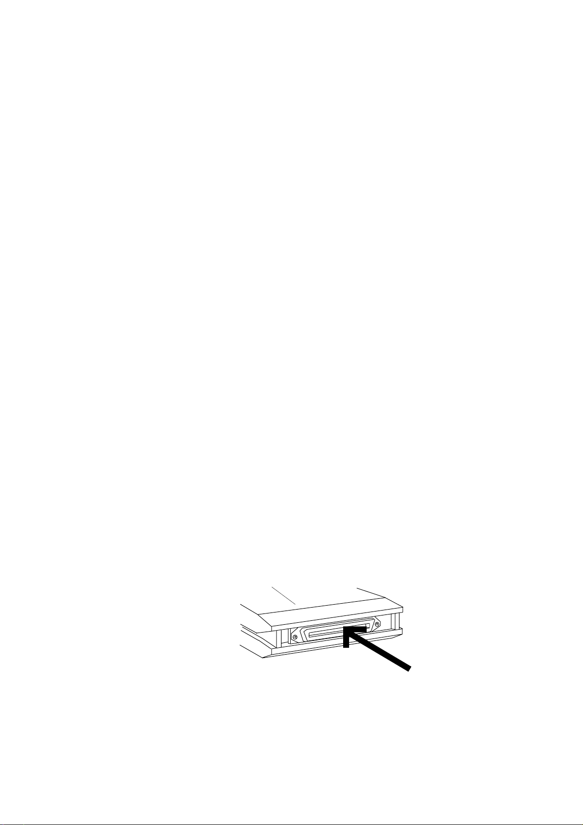
How to use a dust cap (included)
* Plug the included dust cap onto the connector of the D-160's removable hard
disk to protect the disk from static electricity, dust and dirt before you store or
transport the hard disk.
<WARNING>
A hard disk is precision device. Handle it with care and avoid vibration,
humidity, strong magnetic fields, static electricity, dust, etc.
In particular, do not touch the connector with your hands to protect the hard
disk from static electricity.
Removable hard disk
8
Plug the dust cap onto the connector.
(Do not touch the connector with your
hands.)
Page 9

D-160 Owner's Manual (Main features of D-160)
Main Features of D-160
The D-160 is equipped with the following functions:
* Employs a 3.5 inch E-IDE type removable hard disk system.
With an optional 9041 (1.3GB removable hard disk cartridge),
16-track (plus additional 8 tracks) recording and playback.
Total 240 minutes recording/playback time based on a single
track calculation.
* Non-compression recording/16 bit linear quantization and
sampling rates of 44.1kHz and 48kHz (assignable for each Program
and each playback), achieving true CD quality.
“Adat optical I/O” (switchable to S/P DIF), enables 16-track
simultaneous recording (8 analog, 8 digital). Connecting adat
output (x2) of a digital console and adat optical inputs (x2) of the
D-160 allows for 16-track simultaneous digital recording.
* Employs a new disk management method, “FDMS-3” (Fostex Disk
Management System-3). With this method, only the recorded
part consumes the disk space, which allows highly efficient
multitrack recording.
* Program Change function for managing up to 99 Programs (each
Program title editable).
Non-volatile locate memory for each Program, with a pre-roll time
of 0 - 10 seconds.
* Bar/beat Resolution function for storing memory in Bar/Beat units.
* Significantly improved efficiency with an FL display that features
a high-visibility 16-character indication.
* Erase Program function and Delete Program function, convenient
for efficient song management.
* MIDI IN/OUT/THRU terminals support the output of MIDI clock
and Song Position Pointers via an internal Tempo Map, as well as
support MTC/MMC. They also support advanced recorder control
via FEX (Fostex System Exclusive) for advanced functions. These
terminals, along with the functions to store the MTC output offset
by Bar/Beat, to store 24-hour MTC offset, and to display
external MTC (or LTC), will facilitate configuring an integrated
MIDI environment.
9
Page 10

D-160 Owner's Manual (Main features of D-160)
* A programmable internal Tempo Map, with a selection of eleven
time signatures and a quarter note range of 30 to 250, and
Metronome function.
* REC Protect function to prevent accidental recording
* Number Of Events Monitor function that monitors the overflow
of events.
The number of created events can be displayed for each track.
* Installing an optional 8345 TC/SYNC card allows for the MTC-to-
LTC conversion and output, as well as the slave operation for
incoming LTC.
It also allows for synchronization with video reference signals
and Word Clock, as well as output of Word Clock signal to an
external digital device.
* Selectable reference time code (MTC/LTC), with six frame rates
(24/25/30ND/30DF/29.97ND/29.97DF).
* Wide selection of slave types (Vari, S/P DIF, adat, Free), 8345
clock (INT/VIDEO/WORD/AUTO), and WORD out (8345/D-160)
to support various sync environment. Eight Sync Presets available
to recall complex sync settings at once.
* The optional 5041 will add eight +4dBu, analog balanced inputs
(D-SUB25 pin x 1) and 16 outputs (D-SUB25 pin x 2) to the D160’s -10dBV unbalanced I/Os (RCA pin).
* Adat backup as well as conventional DAT backup supported.
Equipped with a standard SCSI interface, which allows for a highspeed data backup to an external SCSI device.
Also, a Save Length Setting function enables backup of the
specified part of a Song.
* +/-6% Vari-pitch function for fine pitch adjustment without
significant tonal quality deterioration.
* Sixteen standard tracks, plus eight additional tracks (Tr. 17-24).
* Track Exchange function for swapping any tracks 1-24.
Track exchange of eight tracks (1-8, 9-16, 17-24) is also available.
* Detachable controller, which can be extended up to 10 meters
with two optional 8551 extension cables (5m).
10
Page 11

D-160 Owner's Manual (Main features of D-160)
* High-speed edit functions, typical for a hard disk, such as non-
destructive copy & paste, move & paste, erase, and undo/redo.
You can also specify the number of repeated operations (up to 99
times).
* Three Time Base (ABS, MTC, Bar/Beat), REMAIN indication based
on each Time Base, and indication of remaining hard disk space.
* Auto Punch In/Out with rehearsal, Auto RTN/Play, Locate ABS 0,
and Locate ABS END function for checking the recording end point.
* Digital scrubbing with the JOG dial, and audio cue with the
SHUTTLE dial.
11
Page 12
D-160 Owner's Manual (Names and Functions)
POWER
POWER
FRONT PANEL
PUNCH
IN / OUT
FRONT PANEL
DIGITAL MULTITRACK RECORDER
RECORD TRACK
HD ACCESSLOCKED MTC IN
(with the detachable controller removed)
(with the detachable remote controller)
D-160
8/167/156/145/134/123/112/101/9
SHIFT
AUTO RTN
CLIPBOARD
AUTO PLAY IN OUT
AUTO
REHEARSAL
TAKE
CLIPBOARD PLAY
LOCATE ABS 0
LOCATE ABS END
DIGITAL MULTITRACK RECORDER
PASTEMOVECOPY
AUTO PUNCH
AUTO RTN
ERASE UNDO REDO
LOCATEPUNCH
VARI PITCH
F FWDREWINDPLAYSTOPRECORD
D-160
ENDIN OUTSTART
EXECUTE
DISP SEL
/YES
TIME BASE SEL
HOLD/ STORE RECALL
PGM CHANGE
EXIT
/NO
ANALOG IN
43
ANALOG OUT
REAR PANEL
DATA
1234567812
9101112131415567816
OPTICAL
9~16 1~8 9~6
OUTPUTINPUT
1~8
12
CAUTION
RISK OF ELECTRIC SHOCK
DO NOT OPEN
:RISQUE DE CHOC ELECTRIQUE
AVIS
NE PAS OUVRIR
SCSI MIDI
WARNING:
TO REDUCE THE RISK OF FIRE OR ELECTRIC
SHOCK. DO NOT EXPOSE THIS EQUIPMENT
TO RAIN OR MOISTURE.
INPUT OUTPUT THRU
Page 13
D-160 Owner's Manual (Names and Functions)
Names and Functions
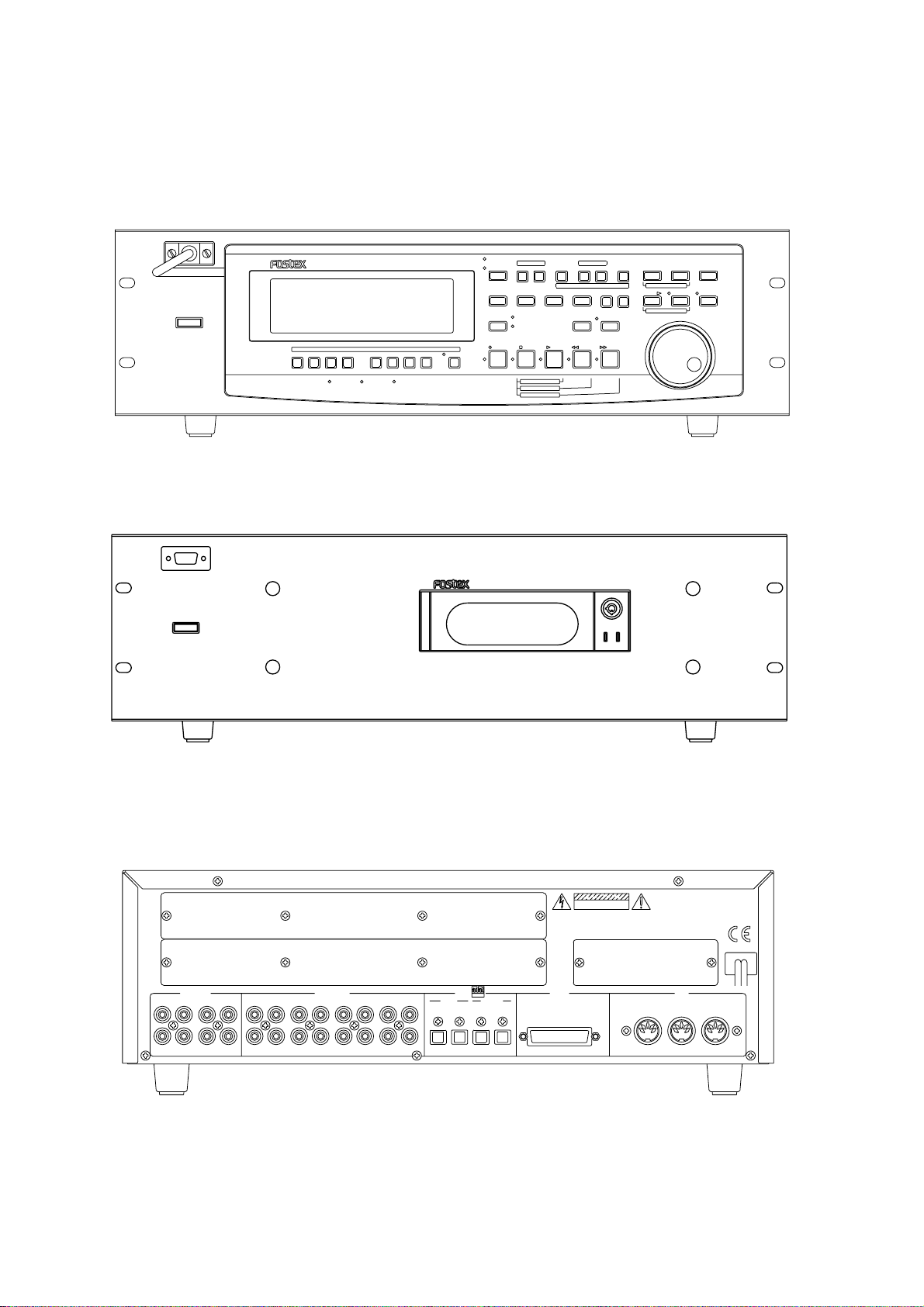
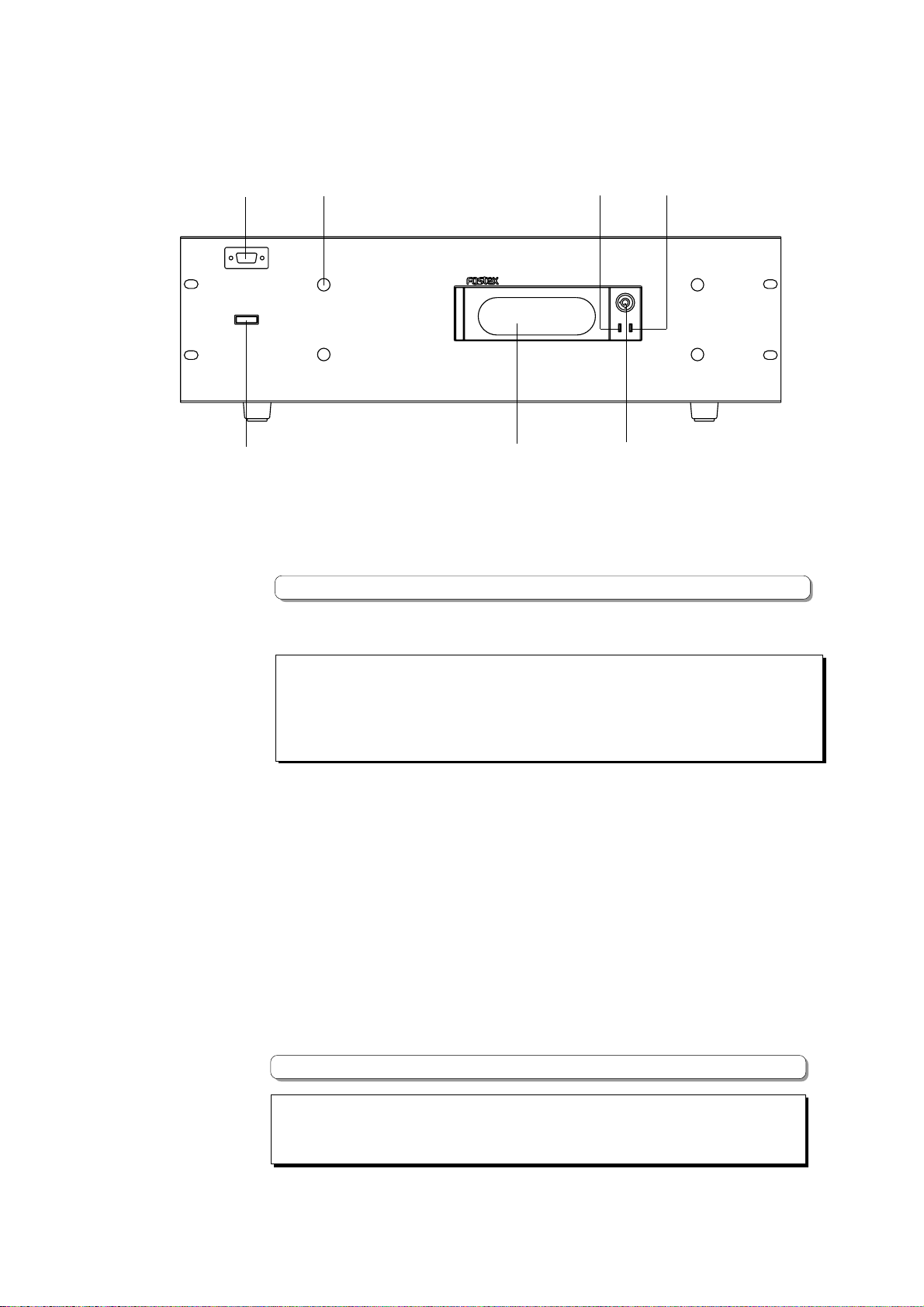
<Front Panel (with the detachable controller removed)>
1
POWER
2
345
DIGITAL MULTITRACK RECORDER
6
D-160
7
1. Detachable remote controller connector
The detachable remote controller is connected here.
You can remove the controller. Connect the optional extension cable (Model 8551) to
extend the distance.
* Refer to page "44" for information on extending the detachable remote controller connection.
2. Power switch
This switch turns the main power to the D-160 on/off.
<WARNING !>
Before turning the power off to the D-160, first quit the Setup mode and make sure that the
recorder section is stopped. Especially, never attempt to turn off the power to the unit while the
hard disk is accessing data (the HD ACCESS LED is lit or flashing).
Otherwise, not only will you lose recorded data, you may damage to the unit.
3. Controller mount
The detachable remote controller is mounted on the front panel.
4. Hard disk access LED
This LED lights up or blinks when the hard disk is writing or reading data. (Same as the
HD ACCESS LED on the detachable remote controller.)
5. Hard disk power LED
This LED lights up if the hard disk operates correctly when you turn the power on to the
unit. If the Lock key is unlocked, the power to the hard disk will not be turned on, and
the LED will not light up.
6. Removable hard disk cartridge slot
This slot is used to insert a removable hard disk cartridge. This system allows you to
replace the hard disk easily.
* Refer to page "41" for more information on how to replace the removable hard disk cartridge.
<Note>
This slot is covered by a dust-proof panel when the unit is shipped from the factory.
Remove this panel in order to insert a cartridge.
13
Page 14
D-160 Owner's Manual (Names and Functions)
<Note>
The D-160 package contains a removable case (without a hard disk). Install your hard disk in
this removable case.
The optional Model 9041 (1.3GB removable hard disk cartridge) contains a hard disk, which
allows you to record and play back about 15 minutes of data (16-tracks recording, FS: 44.1
kHz) without having to install a case.
* Refer to page "39" for more information on the hard disk models that have already been
ested for operation on the D-160.
7. Lock/Unlock key
When you remove or install the hard disk cartridge, you need to lock/unlock here using
the included key.
<Note>
Be sure to turn the power off to the D-160 before locking or unlocking.
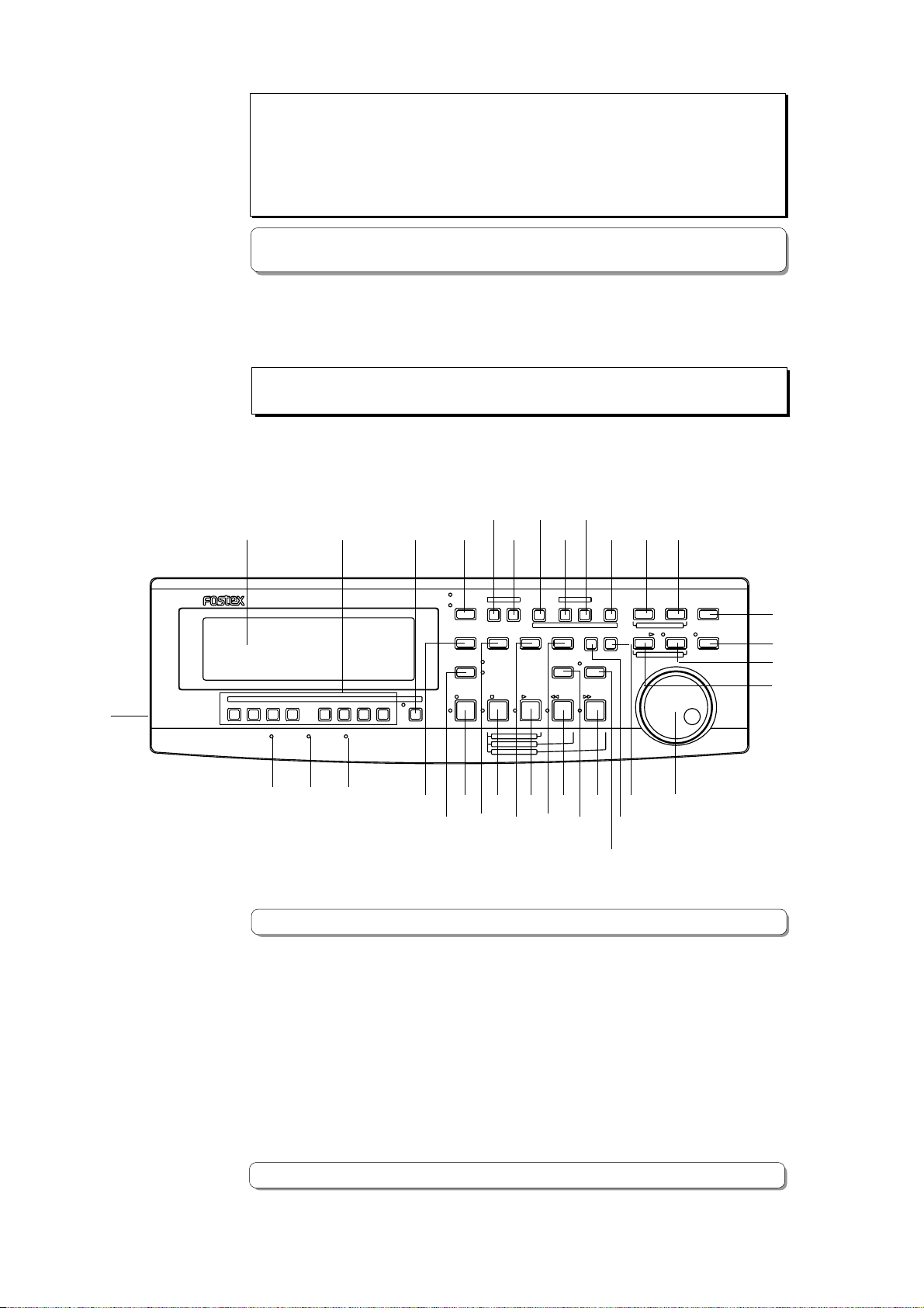
<Detachable Controller>
89 11
10
12
1314161715 18 19
42
PUNCH
IN / OUT
DIGITAL MULTITRACK RECORDER
RECORD TRACK
HD ACCESSLOCKED MTC IN
41
4039
D-160
8/167/156/145/134/123/112/101/9
SHIFT
AUTO RTN
CLIPBOARD
AUTO PLAY IN OUT
AUTO
REHEARSAL
TAKE
CLIPBOARD PLAY
LOCATE ABS 0
LOCATE ABS END
PASTEMOVECOPY
AUTO PUNCH
AUTO RTN
ERASE UNDO REDO
LOCATEPUNCH
VARI PITCH
F FWDREWINDPLAYSTOPRECORD
3328293032
DISP SEL
ENDIN OUTSTART
TIME BASE SEL
HOLD/ STORE RECALL
PGM CHANGE
26
EXECUTE
2425383736353431
EXIT
/YES
/NO
27
8. Meter display
This meter display shows the signal level and settings.
* Refer to the “Display section” on page "25."
9. Record Track Select key [RECORD TRACK]
The Record Track Select key selects "SAFE-READY" for the recording track.
When you press this key once, the track enters the READY status, and the track indication
on the display will blink. Pressing it again changes this status to "SAFE" and the track
indication will go out. When you start recording, the blinking track indication illuminates.
20
21
22
23
When you press only the RECORD button while the track is in the READY status, the track
becomes an input monitor, allowing you to adjust the recording level.
Pressing only the RECORD button again, and the track become a reproduction monitor.
This key is also used to select a track for the Copy & Paste, Move & Paste, Erase, or other
editing operation.
* Refer to page "37" for details about the reproduction monitor and the input monitor.
14
Page 15
D-160 Owner's Manual (Names and Functions)
10. Shift key [SHIFT]
Use this key to choose recording tracks.
When the shift LED lights off, it allows you to choose track 1~8.
When the LED is on, tracks 9~16 can be chosen.
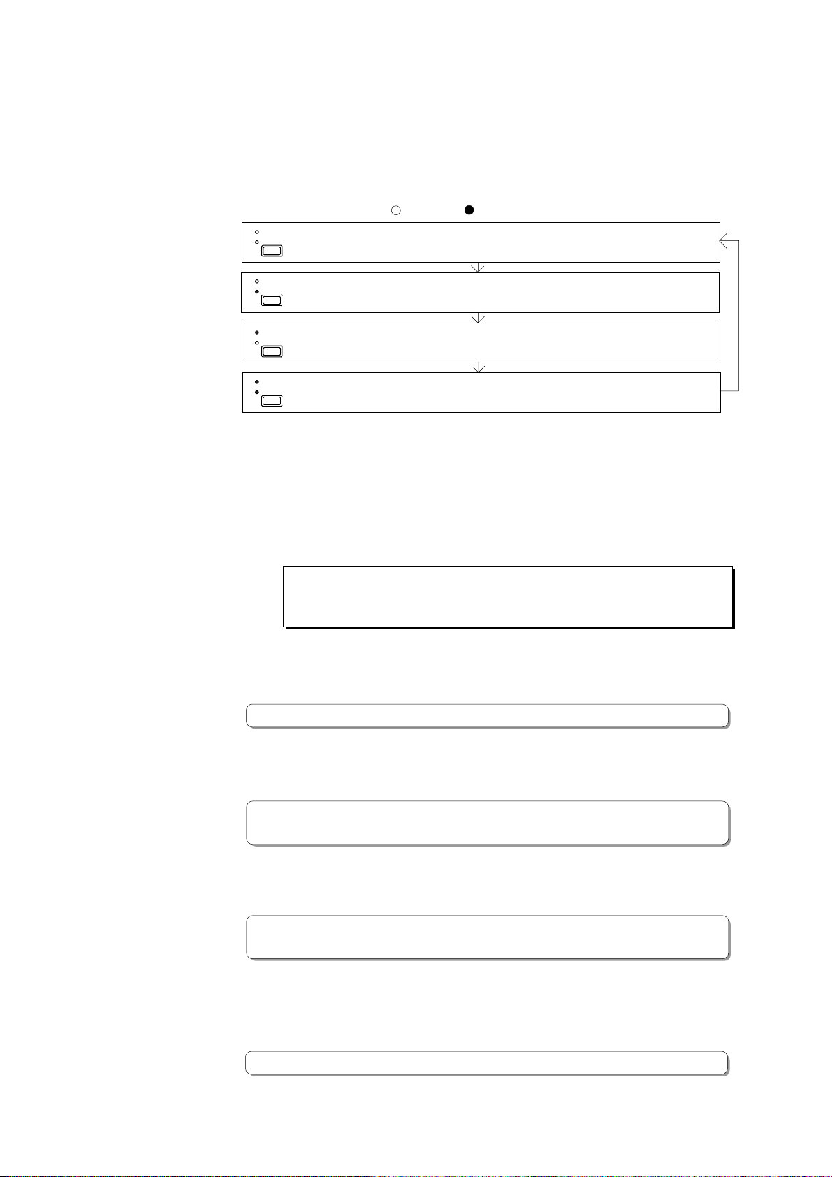
11. Auto Play/Auto Return key
Pressing this key repeatedly will change Auto Play mode, Auto Return mode, and Repeat
mode On/Off as follows: ( : LED off,
AUTO RTN
AUTO PLAY
AUTO RTN
AUTO PLAY
AUTO RTN
AUTO PLAY
AUTO RTN
AUTO PLAY
Auto Repeat ON (Both AUTO PLAY and AUTO RTN LEDs are lit.)
Auto Play/Auto Return OFF (All LEDs are off.)
Auto Play ON (Only the AUTO PLAY LED is lit.)
Auto Return ON (Only the AUTO RTN LED is lit.)
Auto Play mode:
In this mode, playback will start automatically after the START point is located.
This function is effective at any locate points other than the ABS END point.
: LED light up)
Auto Return mode:
When the END point is reached during playback, the START point is automatically
located in this mode. This function is effective only when the START and END points
have been specified.
<Note>
The Auto Return function is works only during playback. In the recording mode, the
START point will not be located automatically when the END point is reached.
Auto Repeat mode:
This mode is a combination of Auto Play and Auto Return, and plays back the part
between the START and END points repeatedly. The auto repeat function is effective
only when the START and END points have been specified correctly.
* Refer to page "67" for details.
12. Clipboard In key [CLIPBOARD IN]
This key is used to store and recall the In point (CLIPBOARD IN point) for the Copy or
Move operation. You can locate a stored CLIPBOARD IN point.
* Refer to page “85” for copying/moving data.
* Refer to page "67" for locating the CLIPBOARD IN point.
13. Clipboard Out key [CLIPBOARD OUT]
This key is used to store and recall the Out point (CLIPBOARD OUT point) for the Copy or
Move operation. You can locate a stored CLIPBOARD OUT point.
* Refer to page "67" for locating the CLIPBOARD OUT point.
* Refer to page "85" for copying/moving data.
14. Auto Return Start key [AUTO RTN START]
This key is used to store and recall the start point (AUTO RTN START point) for the Auto
Return or Auto Repeat operation.
You can locate a stored AUTO RTN START point.
* Refer to page "69" for more information about Auto Return and Auto Repeat.
15
Page 16

D-160 Owner's Manual (Names and Functions)
15. Auto Return End key [AUTO RTN END]
This key is used to store and recall the end point (AUTO RTN END point) for the Auto
Return or Auto Repeat operation.
You can locate a stored AUTO RTN END point.
* Refer to page "69" for more information about Auto Return and Auto Repeat.
16. Auto Punch In key [AUTO PUNCH IN]
This key is used to store and recall the recording start point (AUTO PUNCH IN point) for
the Auto Punch IN/OUT operation. This point is also used as an erase point.
You can locate a stored AUTO PUNCH OUT point.
* Refer to page "75" for more information about Auto Punch In/Out recording.
* Refer to page "85" for more information about pasting data.
* Refer to page "96" for more information about the Erase operations.
17. Auto Punch Out key [AUTO PUNCH OUT]
This key is used to store and recall the recording end point (AUTO PUNCH OUT point) for
the Auto Punch IN/OUT operation. This point is also used as an erase point.
You can locate a stored AUTO PUNCH OUT point.
* Refer to page "75" for more information about Auto Punch In/Out recording.
* Refer to page "96" for more information about the Erase operation.
Memory keys (CLIPBOARD IN, CLIPBOARD OUT, AUTO RTN START, AUTO PUNCH
IN, AUTO PUNCH OUT, and AUTO RTN END keys) have the following common
functions:
* Pressing a Memory key to recall the point the key is storing (or pressing the RECALL
key, and then the Memory key) displays the memory data (time, or bar/beat/clock)
currently stored in that key; then the unit enters data edit mode. To edit data, use
the HOLD/> key or the SHUTTLE dial to move among the digits, and then use the JOG
dial to change the value.
* After you finish editing data, press the STORE key, and then press one of the Memory
keys into which you want to store the point. The edited data will be stored in the
specified Memory key.
* While the current position of the recorder is indicated, press the STORE key, then one
of the Memory keys into which you want to store the data. The current position or the
recorder will be stored in the Memory key. You can do this while the recorder is
running or stopped.
* Press a desired Memory key, and then press the LOCATE key to locate the point stored
in that Memory key (time, or bar/beat/clock).
* All memory data can be stored to Programs 1-99 individually.
* In Setup mode, you can save or load song data for each Program.
* All data will be retained after you turn off the power.
* Refer to page "67" for more information on memory data.
* Refer to page "67" for more information on the Locate function.
* Refer to pages "28" and "49" for more information on the Program Change function.
* Refer to page "102" for more information on saving and loading song data.
16
Page 17
D-160 Owner's Manual (Names and Functions)
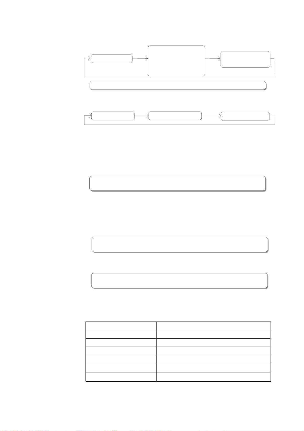
18. Display Select key [DISP SEL]
This key is used to change the display mode. Pressing this key repeatedly will change the
display mode as follows:
The current position
* Refer to pages "26" and "32" for more information about the REMAIN.
Pressing this key while holding down the EXECUTE/YES key will switch the Time Base (*)
as follows. The Time Base can be set when the display shows the recorder's current
position or the available disk space (REMAIN).
ABS (Absolute Time) BAR/BEAT/CLK MTC (MIDI Time Code)
(*) Time Base:
The D-160 uses time display (ABS or MTC) or Bar/Beat/Clock display to indicate the current
position of the recorder section. These displays are called "Time Base." ABS (Absolute Time)
shows the absolute time of the disk, and MTC (MIDI Timecode) shows the relative time obtained
by adding an MTC offset value to the ABS value. Bar/Beat/Clock (BAR/BEAT/CLK) indicates a
position within a piece of music and conforms to the MIDI clock and Song Position Pointers
created on the internal Tempo Map. The tune will be displayed up to 999 bars.
Disk space (remain).
When time base is "MTC", the
MTC or LTC time that is input will
be displayed.(at installed Model
8345)
The Setup mode display
(SETUP is blink) and title
display
* Refer to pages "38" and "145" for more information about MTC and the internal Tempo
Map.
19. Execute/Yes key [EXECUTE/YES]
Press this key to execute the operation when you edit data on the hard disk using the
edit functions such as Paste and Erase, when you put the D-160 into SETUP mode, or
when you set the parameters in the SETUP menu.
Pressing the DISP SEL key while holding down the EXECUTE/YES key allows you to select
the Time Base. (Refer to the explanation about the DISP SEL key.)
* Refer to page "85" for more information about using this key for the Paste or Erase operation.
* Refer to page "137" for more information about using this key in SETUP mode.
20. Exit key/No key [EXIT/NO]
The opposite of the EXECUTE/YES key, this key is used to stop the operation.
* Refer to page "85" for more information about using this key for the Paste or Erase operation.
* Refer to page "137" for more information about using this key in SETUP mode.
21. Recall key [RECALL]
Press this key to recall the stored time value (or Bar/Beat/Clock value).
Pressing this key, and then one of the following keys will display the data stored at the
key you pressed, and you will be able to edit the data.
RECALL key -> CLIPBOARD IN key The Clipboard In point is recalled and the D-160 enters the edit mode.
RECALL key -> CLIPBOARD OUT key The Clipboard Out point is recalled and the D-160 enters the edit mode.
RECALL key -> AUTO PUNCH IN key The Auto Punch In point is recalled and the D-160 enters the edit mode.
RECALL key -> AUTO PUNCH OUT key The Auto Punch Out point is recalled and the D-160 enters the edit mode.
RECALL key -> AUTO RTN START key The Auto Return Start point is recalled and the D-160 enters the edit mode.
RECALL key -> AUTO RTN END key The Auto Return End point is recalled and the D-160 enters the edit mode.
RECALL key -> LOCATE key The Locate key data is recalled and the D-160 enters the edit mode.
To exit edit mode, press the EXIT/NO key, DISP SEL key, or STOP button.
17
Page 18
D-160 Owner's Manual (Names and Functions)
* Refer to page "85" for more information about the clipboard.
* Refer to page "75" for more information about Auto Punch In/Out recording.
* Refer to page "70" for more information about Auto Return.
22. Store key [STORE]
This key is used to store a time value (or Bar/Beat/Clock value) to one of the memory
keys. Pressing this key, and then one of the following keys will cause the data shown on
the display to be stored to the corresponding memory key you pressed. Pressing the
STORE key while holding down the HOLD/> key will change a Program.
STORE key -> CLIPBOARD IN key Data is stored as a Clipboard In point.
STORE key -> CLIPBOARD OUT key Data is stored as a Clipboard Out point.
STORE key -> AUTO PUNCH IN key Data is stored as an Auto Punch In point.
STORE key -> AUTO PUNCH OUT key Data is stored as an Auto Punch Out point.
STORE key -> AUTO RTN START key Data is stored as an Auto Return Start point.
STORE key -> AUTO RTN END key Data is stored as an Auto Return End point.
STORE key -> LOCATE key Data is stored as a LOCATE key data.
The stored data can be used as a locator.
The stored data can be used as a locator.
The stored data can be used as a locator.
The stored data can be used as a locator.
The stored data can be used as a locator.
The stored data can be used as a locator.
After pressing this key, if you wish to cancel the store operation, press the EXIT/NO key,
DISP SEL key, or STOP button.
* Refer to page "85" for more information about the clipboard.
* Refer to page "28" and "49" for more information about Program Change function.
* Refer to page "67" for more information about the Locate function.
* Refer to page "75" for more information about Auto Punch In/Out recording.
* Refer to page "70" for more information about Auto Return.
23. Hold/Digit Move key [HOLD/>]
Pressing this key while the recorder transport is operating will hold the time value (or
Bar/Beat/Clock value), display the value on the screen, and will place the D-160 into edit
mode. If you press this key while the recorder section is stopped, the D-160 will enter
edit mode. Pressing this key repeatedly allows you to select the digit (column) to edit.
To cancel edit mode, press the STOP button, DISP SEL key, or EXIT/NO key.
Pressing the STORE key while holding down the HOLD/> key will change the Program.
* Refer to pages "67" and "85" for more information about using this key.
24. Jog/Shuttle dial
Jog dial (inside):
Turning the JOG dial while the recorder is stopped performs digital scrubbing in either
direction, which allows you to check the audio and locate a point without any change
in pitch.
The JOG dial is also used to change values in the data edit mode or when the pitch
data is displayed. It also allows you to select a parameter to set in Setup mode.
Shuttle dial (outside):
FWD and REW direction shuttle operation in the STOP mode is possible at +/-1 ~ 64
times fast winding in the no sound state. On the other hand, FWD and REW direction
shuttle operation in the PLAY mode is possible in the CUE playback mode at +1 ~ 8 and
-1 ~ -7 times speed while cueing. In addition, while in the display edit mode, the
editing point can be moved in the same way as by the HOLD/> key.
* Refer to pages "67" and "85" for more information about the editing the memory data.
* Refer to page "137" for more information about Setup mode.
18
Page 19
D-160 Owner's Manual (Names and Functions)
25. Redo key [REDO]
Pressing this key after you press the UNDO key restores the status obtained before you
undo recording or editing. This key is activated only when the recorder transport section
is stopped.
* Refer to pages "75" and "85" for more information about the Redo operation.
26. Undo key [UNDO]
After using an edit function such as Paste, or Erase, or after auto punch in/out recording,
pressing this key will restore the previous status before editing or recording.
This key is activated only when the recorder transport section is stopped.
* Refer to pages "75" and "85" for more information about the Undo operation.
27. Erase key [ERASE]
This key is used to erase a specified area or all data after a specified point on certain
“READY” track(s), or all the data in a specified Program.
Use the Auto Punch In/Out points and the RECORD TRACK select key to specify the area to
erase.
To erase all data in a Program, press the STORE key while holding down the HOLD/> key
to select the Program, then press the ERASE key.
All data recorded in the Program will be erased. You do not need to set a track in READY
mode.
* Refer to page "96" for more information about the Erase operation.
28. Vari-pitch key [VARI PITCH]
Use this key to turn the Vari-pitch function on and off. When this function is enabled, the
corresponding LED lights up. When this function is disabled, the LED turns off.
The range of pitch variation for playback and recording is +/-6.0%, in 0.1% steps.
Press the RECALL key, and then the VARI PITCH key to display the current pitch data.
To change the pitch data, use the JOG dial to change the value while the pitch data is
displayed.
You can also change the playback speed when the data is being played back with the Varipitch function ON.
* To quit the pitch data display, press the EXECUTE/YES key, the EXIT/NO key, or the
STOP button.
<Note>
Even when the vari-pitch data is set to 0.0%, pressing this key will turn the LED on.
<Note>
You cannot change the pitch data while recording. If the Vari-pitch function was on, the unit will
use the pitch data previously set.
<Note>
The Vari-pitch function will be automatically turned off in the following situations:
* When you turn on the power to the unit (The pitch data will be reset to 0.0%.)
* When you set Slave mode ON. (The pitch data remembers the previous setting.)
* When you set up the digital input tracks and “DIGITAL” appears on the display. (The pitch data
remembers the previous setting.)
If you have installed an optional Model 8345 TC/SYNC card in the D-160 and you have set the
“Word Out?” menu in the Setup mode to “8345,” the Vari-pitch function turns on even during digital
input via DIGITAL IN.
* Refer to page "56" for more information on the Vari-pitch function.
* Refer to page "123" for more information on Slave mode.
* Refer to page "60" for more information on digital signals.
19
Page 20
D-160 Owner's Manual (Names and Functions)
29. Paste key [PASTE]
Press this key to copy data or move data that has been copied to the clipboard to a
location stored at the AUTO PUNCH IN key. The data will be pasted at the point stored in
the Auto Punch In key. You can select the paste destination track using the RECORD
TRACK select key. A destination track to which data is pasted is identical to the source
track. This key is activated only when the recorder transport section is stopped.
* Refer to page "85" for more information about the Copy & Paste, and Move & Paste operation.
30. Move key [MOVE]
This key is used to enter into the clipboard data stored in memory by the CLIPBOARD IN/
OUT keys. Pressing the MOVE key will store the data in the Clipboard as Move data.
To enter data to be moved, one or more tracks must be readied, and a correct value must
be stored for the In and Out points. If you attempt to enter data when all tracks are safe,
all track indications and "Select Track!" indication on the display will blink to warn you.
If a correct value is not set for the Clipboard In or Out points, a warning message of “Void
In Point!” or “Void Out Point!” will appear.
* Refer to page "85" for more information about the Copy & Paste, and Move & Paste operation.
31. Copy key [COPY]
This key is used to copy data stored in the memory using the CLIPBOARD IN/OUT keys.
Pressing the COPY key will store the data in the Clipboard as Copy data. To execute the
copy operation, one or more tracks must be readied, and a correct value must be stored
for the In and Out points. If you attempt to copy data when all tracks are safe, all track
indications and a "Select Track!" indication on the display will blink to warn you.
If a correct value is not set for the Clipboard In or Out points, a warning message of “Void
In Point!” or “Void Out Point!” will appear.
* Refer to page "85" for more information about copying data.
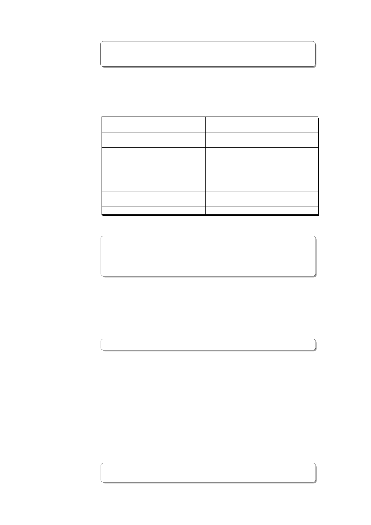
32. Auto Punch Mode On/Off key [AUTO PUNCH]
Switch this key ON for auto punch in/out.
When you press this key while a correct value is stored to the AUTO PUNCH IN key and the
AUTO PUNCH OUT key, both the REHEARSAL LED and TAKE LED will blink, indicating that
Auto Punch mode is on. (If a correct value is not stored, pressing the AUTO PUNCH key
will not turn the parameter ON, and the message “Void Out Point!” will appear.)
Pressing the PLAY button under this condition will put the unit into "Rehearsal mode" for
Auto Punch In/Out recording. Pressing the PLAY button and RECORD button simultaneously
will put the unit into "Take mode."
There are five combinations of the REHEARSAL LED and TAKE LED that indicate the status
of the unit regarding auto punch recording:
<Note>
If a correct value is not stored, pressing the AUTO PUNCH key will not enable the function,
and the message “Void Out Point!” will appear.
If a correct value is not stored, pressing the AUTO PUNCH key will not turn on the function, and the
message “Void Out Point” will alert you. In this case, set a correct value for the Auto Punch In/Out point.
Also, the function is not turned on when you press the AUTO PUNCH key if the disk does not have
enough recording space. The display will indicate “-**h**m**s**f Over.”
Auto Punch mode OFF Both REHEARSAL LED and TAKE LED are off.
Auto Punch mode ON Both REHEARSAL LED and TAKE LED are blinking.
Auto Punch Take mode Only the TAKE LED (red) is lit.
Auto Punch Rehearsal mode Only the REHEARSAL LED (green) is lit.
Rehearsal mode entered by Only the REHEARSAL LED (green) is blinking.
means of MMC or foot switch
* Refer to page "75" for more information about the Punch In/Out.
20
Page 21
D-160 Owner's Manual (Names and Functions)
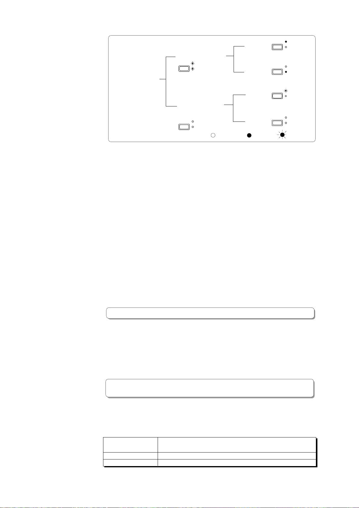
AUTO
REHEARSAL
Punch In/Out mode and LED display
Auto Punch In/Out mode
AUTO
REHEARSAL
PUNCH
TAKE
Punch In/Out mode
Manual Punch In/Out using a
footswitch or MMC. (Auto
Punch mode OFF.)
AUTO
REHEARSAL
PUNCH
TAKE
:go off
Rehearsal
Take
Rehearsal
Take
:light up
PUNCH
AUTO
PUNCH
AUTO
PUNCH
AUTO
PUNCH
TAKE
REHEARSAL
TAKE
REHEARSAL
TAKE
REHEARSAL
TAKE
:blink
33. Locate key [LOCATE]
Press this key to locate a position.
You can locate a point (memory data) (time, or bar/beat/clock) stored in the Memory
keys when you press a Memory key (CLIPBOARD IN, CLIPBOARD OUT, AUTO RTN START,
AUTO PUNCH IN, AUTO PUNCH OUT, or AUTO RTN END), and then press the Locate key.
Data stored in the Locate key is the most-recently located position expressed as a time
value (bar/beat/clock). If you wish to locate the same point repeatedly, then press this
key repeatedly. If you locate a position at a different time value or bar/beat/clock value,
the data will be updated. Pressing the RECALL key, and then the LOCATE key will display
the data stored in the LOCATE key (time or bar/beat/clock), and put the D-160 in the
data edit mode. To edit the data, use the HOLD/> key or the SHUTTLE dial to move around
the digits, and then use the JOG dial to change their value.
When you finish editing the data, you can store a particular locate point by pressing the
STORE key, and then the LOCATE key. You can also store a locate point by pressing the
STORE key, and then the LOCATE key while the recorder’s current point is shown.
Also, pressing the HOLD/> key to enter data edit mode, and then pressing the LOCATE
key when you finish editing, will allow you to locate the edited position (bar/beat/clock)
directly. This data can be stored individually to each Program P1-P99.
In the SETUP mode, you can also save and load the song data to and from each Program
individually. The data will be retained after you turn off the power to the unit.
* Refer to page "67" for more information about the Locate function.
34. Record button [RECORD]
Pressing only this button places the readied tracks into input monitoring status.
Pressing this button again will reset the tracks to playback monitoring. (The RECORD LED
will blink when the readied tracks are in input monitoring status.)
Pressing the PLAY button while holding down this button will place the readied tracks
into recording. At this time, the PLAY LED and RECORD LED will light, and the readied
track indication will be light steadily (instead of blinking).
* Refer to page "37" of the "Before Operating" section for more information about input
monitoring and reproduce monitoring.
35. Stop button [STOP]
Pressing this button will stop the transport section of the recorder.
Pressing the PLAY, REWIND, or F FWD button while holding down this button will cause
the D-160 to perform the following operation:
STOP + PLAY Clipboard playback (The STOP LED will flash and the PLAY LED will
light up.) *3
STOP + REWIND Locate ABS 0 *4
STOP + F FWD Locate ABS END *5
21
Page 22
D-160 Owner's Manual (Names and Functions)
Pressing the STOP button will abort the editing operations and display the current
position of the recorder, if you wish to:
* quit the data edit mode,
* cancel the recall or store operation,
* quit the pitch data display,
* cancel the edit operation, such as pasting, or
* cancel the SETUP menu settings.
Pressing the foot switch while holding down this button allows you to turn the punch in/
out rehearsal mode ON/OFF.
*3 Clipboard playback:
The D-160 plays back the copy data or move data for the Clipboard. During audio playback
of the copy or move data, the FL will display the time length and data type (“Copy Clip
Play!” or “Move Clip Play!"), and the copy or move source track indicator will flash, enabling
you to quickly determine the track and data type.
*4 Locate ABS 0:
The D-160 will locate the top of the selected Program (ABS TIME: 00m: 00s: 00f).
*5 Locate ABS END:
The D-160 will locate the end of the recorded data on the Program (ABS END).
* These operations can be executed only on real tracks 1 ~ 16.
* Refer to page "32" of the "Before Operating" section for more information about ABS 0 and
ABS END.
* Refer to page "81" for more information about Punch In/Out recording using the foot switch.
36. Play button [PLAY]
Pressing this button will cause the recorder to play back.
Pressing this button while holding down the RECORD button will start recording.
Pressing this button while holding down the STOP button will perform the Clipboard
playback operation. Refer to the section “STOP Button” for more information on the
Clipboard playback.
Pressing the PLAY button during recording will stop recording.
37. Rewind button [REWIND]
Pressing this button while the recorder section is stopped will rewind data at 30 times
speed. Pressing this button in Play mode will cue data (you can hear sound while rewinding)
at five times speed.
Pressing this button while holding down the STOP button will perform the "LOCATE ABS
0" operation, and immediately locate the beginning of the Program (ABS TIME: 00m: 00s:
00f). (Refer to the "STOP button" section for more information about LOCATE ABS 0.)
38. Fast Forward button [F FWD]
Pressing this button while the recorder section is stopped will fast forward data at 30
times speed. Pressing this button in Play mode will cue data (you can hear sound during
the fast forward operation) at five times speed.
Pressing this button while holding down the STOP button will initiate the "LOCATE ABS
END" operation, and immediately locate the end of the recorded data on the Program
(ABS END). (Refer to the "STOP button" section for more information about LOCATE ABS
END.)
39. Locked LED [LOCKED]
The Locked LED will blink when the D-160 is setup as slave mode.
It will light on when the lock is achived.
* Refer to page "123" for more information about "Slave Mode Function."
22
Page 23
D-160 Owner's Manual (Names and Functions)
40. Hard disk access LED
This LED lights up or blinks when the hard disk is writing or reading data.
<CAUTION>
Do not turn the power off while this LED is lit or blinking. Otherwise, data on the hard disk may
be damaged.
41. MIDI Time Code In LED [MTC IN]
This LED lights up when MTC (MIDI Time Code) is input from an external MIDI device to
the MIDI IN connector of the D-160.
42. Punch In/Out jack [PUNCH IN/OUT] (Connector: PHONE jack)
Connecting the optional foot switch will let you control punch In/Out (and rehearsal)
recording. Use a Fostex Model 8051 foot switch.
<Note>
Be sure to use an “unlatch type” foot switch if you use a foot switch other than the Model 8051.
Otherwise, a malfunction could occur.
* Refer to page "81" for information about Punch In/Out recording using the foot switch.
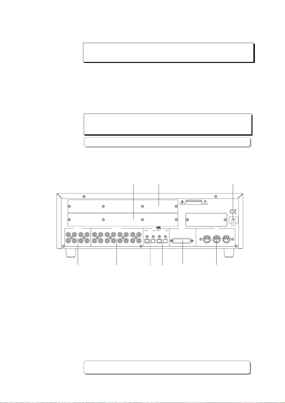
<Rear Panel>
ANALOG IN
43
43
43. Input jack [ANALOG IN 1-8]
Analog audio signal from the mixer is routed here.
Connect this jack to the Group out (BUSS OUT) connector of the mixer.
44. Output jack [ANALOG OUT 1-16]
Analog audio signal of the D-160 is output here.
Connect this jack to the TAPE IN connector of the mixer.
ANALOG OUT
49
1234567812
9101112131415567816
50
DATA
9~16 1~8 9~6
OPTICAL
OUTPUTINPUT
44 45 46
(connector: RCA pin)
CAUTION
RISK OF ELECTRIC SHOCK
DO NOT OPEN
:RISQUE DE CHOC ELECTRIQUE
AVIS
NE PAS OUVRIR
1~8
SCSI MIDI
47
(connector: RCA pin)
WARNING:
TO REDUCE THE RISK OF FIRE OR ELECTRIC
SHOCK. DO NOT EXPOSE THIS EQUIPMENT
TO RAIN OR MOISTURE.
INPUT OUTPUT THRU
48
51
45. Data Input connector [DATA INPUT 1-8, 9-16]
(connector: OPTICAL)
Use this connector to load song data (audio + setup data) from an external device to the
D-160. It is also used to input S/P DIF digital signal (from a DAT, CD, or MD) or adat
digital signal (from RD-8, CX-8, or adat). DATA INPUT 9-16 is constantly fixed to "adat"
input.
* Refer to pages "102" and "165" for information about "LOAD" function.
* Refer to page "60" for information "Digital Recording."
23
Page 24

D-160 Owner's Manual (Names and Functions)
<Note>
Use the DATA INPUT 1-8 connector to load song data to the D-160.
Do not use the DATA INPUT 9-16 connector with load .
46. Data Output connector [DATA OUTPUT 1-8, 9-16]
Use this connector to save song data (audio + setup data) from the D-160 to an external
device. It is also used to output S/P DIF digital signal or adat digital signal to an external
digital device. DATA OUTPUT 9-16 is constantly fixed to "adat" output.
(connector: OPTICAL)
<Note>
Use the DATA OUTPUT 1-8 connector to save song data from the D-160.
Do not use the DATA OUTPUT 9-16 connector with save.
* Refer to pages "102" and "168" for information about "SAVE" function.
* Refer to page "60" for information "Digital Recording."
47. SCSI connector [SCSI]
This is the connector which enables an external SCSI device to be connected.
It allows you to save or load song data.
Use the D-sub 25-pin cable for Macintosh designated by each SCSI device.
* Refer to pages "108" and "166" for information about "SCSI."
(connector: D-sub 25-pin)
48. MIDI Input/Output/Thru connector [MIDI INPUT/OUTPUT/THRU]
(connector: DIN 5-pin)
MIDI INPUT:
Connect the MIDI OUT connector of an external MIDI device here.
The D-160 can be controlled remotely via an external MMC (MIDI Machine Control) or
FEX (Fostex System Exclusive Message).
MIDI OUTPUT:
Connect the MIDI IN connector of the external MIDI device here.
The D-160 will output MTC (MIDI Time Code), MIDI Clock signal, MMC (MIDI Machine
Control) response, and FEX (Fostex System Exclusive Message) response.
MIDI THRU:
This connector outputs the input signal at the MIDI INPUT connector without modification.
When using multiple D-160s via MIDI, connect this terminal to the MIDI INPUT connector
of the second D-160. Refer to page "117" for details.
49. Panel A for an optional card
This is the panel used for installing the optional Model 5041 (balanced 8-16 I/O card).
Using the Model 5041 allows for balanced analog signal input and output. In general,
leave the panel in place.
50. Panel B for an optional card
This is the panel used for installing the optional Model 8345 (D-160 TC/SYNC card).
Using the Model 8345 makes the D-160 have LTC input and output connectors.
Also, the sync lock with video and word clock will be possible. In general, leave the panel
in place.
51. Power cable
Connect the power cable to an AC outlet of the specified voltage.
24
Page 25
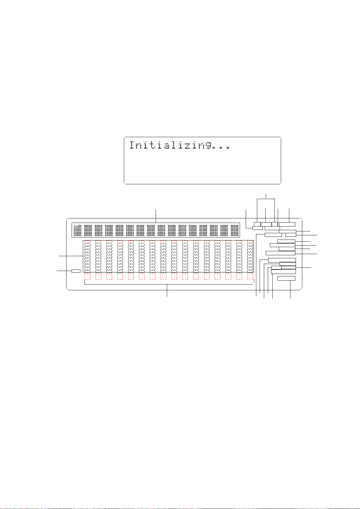
<Display Section>
The D-160 display integrates the level meter of a high-visibility FL tube with a 16 digits and
35 dot message display.
The level meter shows the Track 1-16 output level of the recorder section. The time display
shows the current time of the recorder section using ABS TIME (Absolute time), MTC (MIDI
timecode), or MIDI BAR/BEAT (bar/beat). This display also shows messages required for
interactive operation. The following section explains the display functions and provides with
some examples.
1. Display shown when the power is turned on
When you turn on the power to the D-160, the display shows "Initializing..." (Initializing.
Please wait.), and the time display shows the time using the time base (ABS, MTC, or BAR/
BEAT/CLK) that was selected before the power was turned off.
OL
12
18
24
30
42
∞
_
2. Preset display
D-160 Owner's Manual (Names and Functions)
0
3
6
9
91011121314151687654321
12
44.1kHz
15
3
3 6 9
17
TC MTC IN OFFSET
ABS SETUP CHASE
OL
0
3
6
9
1
12
18
24
30
42
∞
_
91011121314151687654321
7
2
5
LOCATE
REMAIN PGM
FORMAT
SIGNATURE
TEMPO
44.1kHz 48kHz
COMPLETED !
SURE ?
MIDI CHASE
SAVE LOAD
EXT SYNC
DIGITAL
10
8
9
11
4
9
9
13
16
3
14
1. Level meter
The level meter shows the recorder output level and the recording level for Tracks 1-16.
2. Track indication
The track indication blinks when the corresponding track is ready. It turns off when the
track is safe, and is lit during recording.
3. ABS, MTC, SIGNATURE
When Time Base uses ABS time, “ABS” lights up. With MTC time, “MTC” lights up, and with
BAR/BEAT/CLK indication, “SIGNATURE” lights up.
4. LOCATE
This LED lights up when the unit enters data edit mode, enabling you to edit data.
Pressing the LOCATE key while this LED is lit will cause the D-160 to locate the position of
the displayed time or the bar/beat/clock value.
5. REMAIN
Refer to "2. Switching the display using the DISP SEL key."
6. SETUP
Refer to "2. Switching the display using the DISP SEL key."
7. COMPLETED!
This message indicates that an operation such as copy, move, and paste has been completed.
25
Page 26

D-160 Owner's Manual (Names and Functions)
8. SURE?
This message is shown to confirm whether or not you wish to execute a certain operation.
9. LOAD, SAVE, FORMAT, MTC OFFSET, TEMPO
When the unit enters Setup mode, the selected parameter name will appear here.
The parameter name also appears on the 35 dot message Display.
10. MIDI
This indication lights up when the D-160 receives effective MIDI messages from an external
MIDI device.
11. DIGITAL
This indication lights up when the D-160 is receiving a digital signal properly at the DATA
INPUT connector while loading data from a external digital equipment (CD, MD etc.).
If this indication is blinking, the digital signal is not being received correctly.
12. 35 dot message Display
This display indicates the ABS time, MTC time, BAR/BEAT/CLK time value or bar/beat/
clock value, a Program number, and a parameter name in the Setup mode.
13. CHASE
This indication flashes when the D-160 is in Slave mode, and lights up when the unit locks
to the sync signal.
14. 44.1kHz, 48kHz
This displays the sampling rate of the Program you are currently working.
During DIGITAL input of S/P DIF, the 44.1kHz or 48kHz indication will blink when the FS
setteing is different between the digital signal that is input and that in D-160.
15. MTC IN, TC IN
With the optional Model 8345 TC/SYNC card installed, this will be lit when MTC or LTC is
externally input.
16. PGM
This flashes when the D-160 is enterd in the program setup and program change modes.
17.
At playback of a no sound section, if the FL tube " ∞" symbol only is lit, the level of that
track will be lower than 43dB but it also indicates that an Audio File exists in the lighted
track.
You proceed as is but the hard disk is occupied in excess by this Audio File.
If this Audio File is unneeded, disk capacity can be economizied by erasing this section.
Likewise, during playback, if nothing is lit in the FL tube " ∞" section, it means that
Audio data of this track is "ALL 0" and the hard disk is not occupied by this.
3. Switching the display using the DISP SEL key.
Let's assume that you turned off the power while the time display was using a time base of
"ABS," and then you turned the power on again. The D-160 time display will again use a time
base of "ABS." (Underline->Displayed program number)
ABS TIME display
ABS
OL
0
3
6
9
12
18
24
30
42
∞
_
91011121314151687654321
44.1kHz
26
Page 27
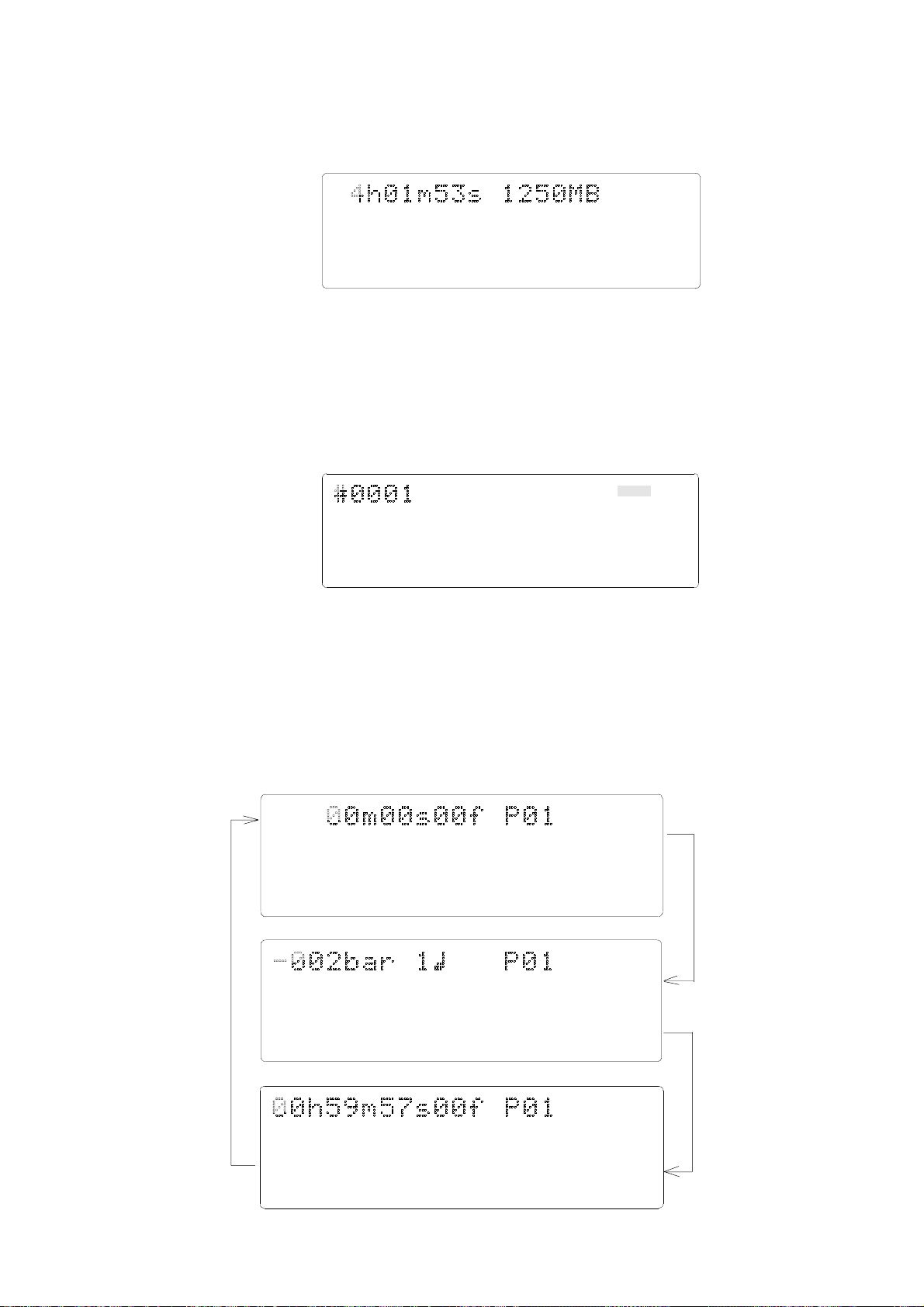
D-160 Owner's Manual (Names and Functions)
At this time if you press the DISP SEL key, the Disk Remain display will appear. (Both
recordable time and hard disk capacity remaining will be converted to mono track and
expressed in time and megabites.)
DISK REMAIN display
OL
0
3
6
9
12
18
24
30
42
∞
_
91011121314151687654321
REMAIN
44.1kHz
If "BAR/BEAT/CLK" is selected for the timebase (explained later), the DISK REMAIN
indication will show a value (in terms of the number of measures) calculated based on the
last beat/tempo data on the tempo map of the recorded song.
When you press the DISP SEL key again, the Setup mode display will appear.
At this time, the D-160 has not entered the Setup mode. To put the D-160 into the Setup
mode, press the EXECUTE/YES key. After pressing the EXECUTE/YES key, if you wish to go
back to the previous status, press the EXIT/NO key.
Setup mode display ("SETUP" indication is flashing)
SETUP
OL
0
3
6
9
12
18
24
30
42
∞
_
91011121314151687654321
If you press the DISP SEL key again, the screen will return to the "ABS TIME" display.
44.1kHz
4. Switching the Time Base display using the EXECUTE/YES key and
DISP SEL key
When the screen is showing the ABS TIME or REMAIN display, if you press the DISP SEL key
repeatedly while holding down the EXECUTE/YES key, the TIME BASE display will change
cyclically. You can select one of the following Time Base displays.
ABS (Absolute Time)
ABS
OL
0
3
6
9
12
18
24
30
42
∞
_
91011121314151687654321
BAR/BEAT/CLK (Bar/Beat/Clock)
OL
0
3
6
9
12
18
24
30
42
∞
_
91011121314151687654321
MTC (MIDI Timecode)
MTC
44.1kHz
SIGNATURE
44.1kHz
OL
0
3
6
9
12
18
24
30
42
∞
_
91011121314151687654321
44.1kHz
27
Page 28
D-160 Owner's Manual (Names and Functions)
5. Changing Programs using the STORE key and the HOLD/> key
* About the Program Change function
The Program Change function divides the hard disk space into up to 99 parts to
accommodate 99 separate Programs (P01-P99 — as long as available recording
time allows) so you can record, play back, edit, and archive (save and load) data
for each Program individually.
For example, the first song can be Program 1, the second song can be Program 2,
etc. You need to recall the desired Program before you start recording, playback,
editing, or archiving.
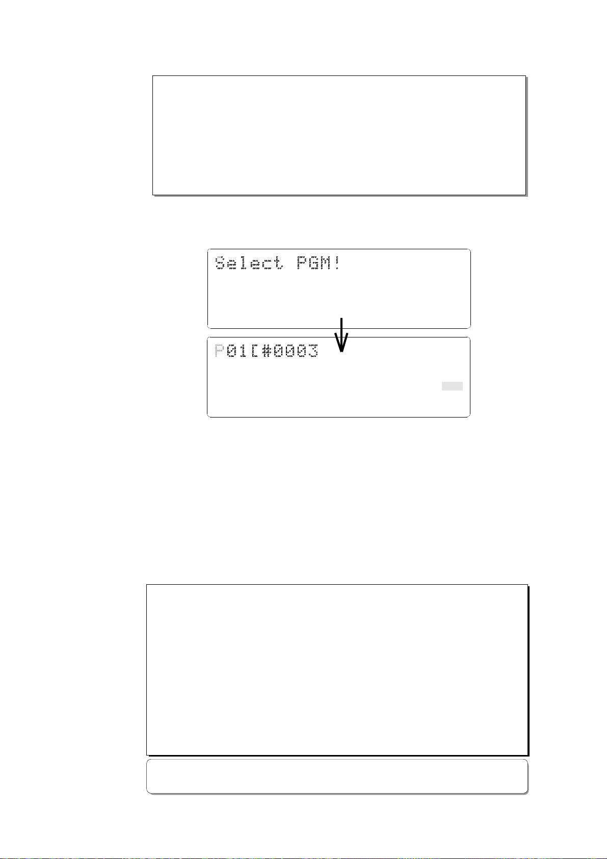
Pressing the STORE key while holding down the HOLD/> key will cause the D-160 to enter
Program select mode, display the message “Select PGM !”, followed by the current Program
and Program number and a flashing “SURE?” indication.
OL
0
3
6
9
12
18
24
30
42
∞
_
OL
0
3
6
9
12
18
24
30
42
∞
_
91011121314151687654321
91011121314151687654321
PGM
44.1kHz
PGM
44.1kHz
SURE?
You can select the desired Program from the already setup Programs by rotating the JOG
dial while the Program number and “SURE ?” are flashing. ("#0003" is the current program
title.)
After you select a Program, press the EXECUTE/YES key to return to the selected Program’s
ABS indication.
The Time Base display will indicate the selected Program’s Time Base, since you can set
the Time Base for each Program individually.
To change the Time Base display after you have selected the desired Program, press the
DISP SEL key while holding down the EXECUTE/YES key.
Pressing only the DISP/SEL key will take you to the REMAIN display based on the current
Time Base.
<Notes>
* If you turn the JOG dial while the ABS display or MTC display indicates a Program number,
the Program number indication will change to the sub-frame indication. However, if you
operate a transport button, such as the PLAY button or the Stop button, or if you turn the
SHUTTLE dial, the sub-frame indication will change back to the Program number indication.
(The Program number shown on the BAR/BEAT/CLK display will not change.)
* The maximum total recording time of all setup Programs (up to 99 Programs) equals the
available recording time of the hard disk. For example, if you use an optional Model 9041
(1.3GB removable hard disk cartridge), the available 16-track recording time is about 15
minutes (with a sampling rate of 44.1kHz). If you have recorded 10 minutes of data in
Program 1, you can record 5 minutes for the total time of the rest of Programs. That is, you
can record data totalling 15 minutes, regardless of whether you use all setup Programs or
record only one Program.
* Refer to “2-1. Setting up a Program” and “2-2. Program Change” on pages 49-51 for more
information on how to setup a new Program and use the Program Change function.
28
Page 29
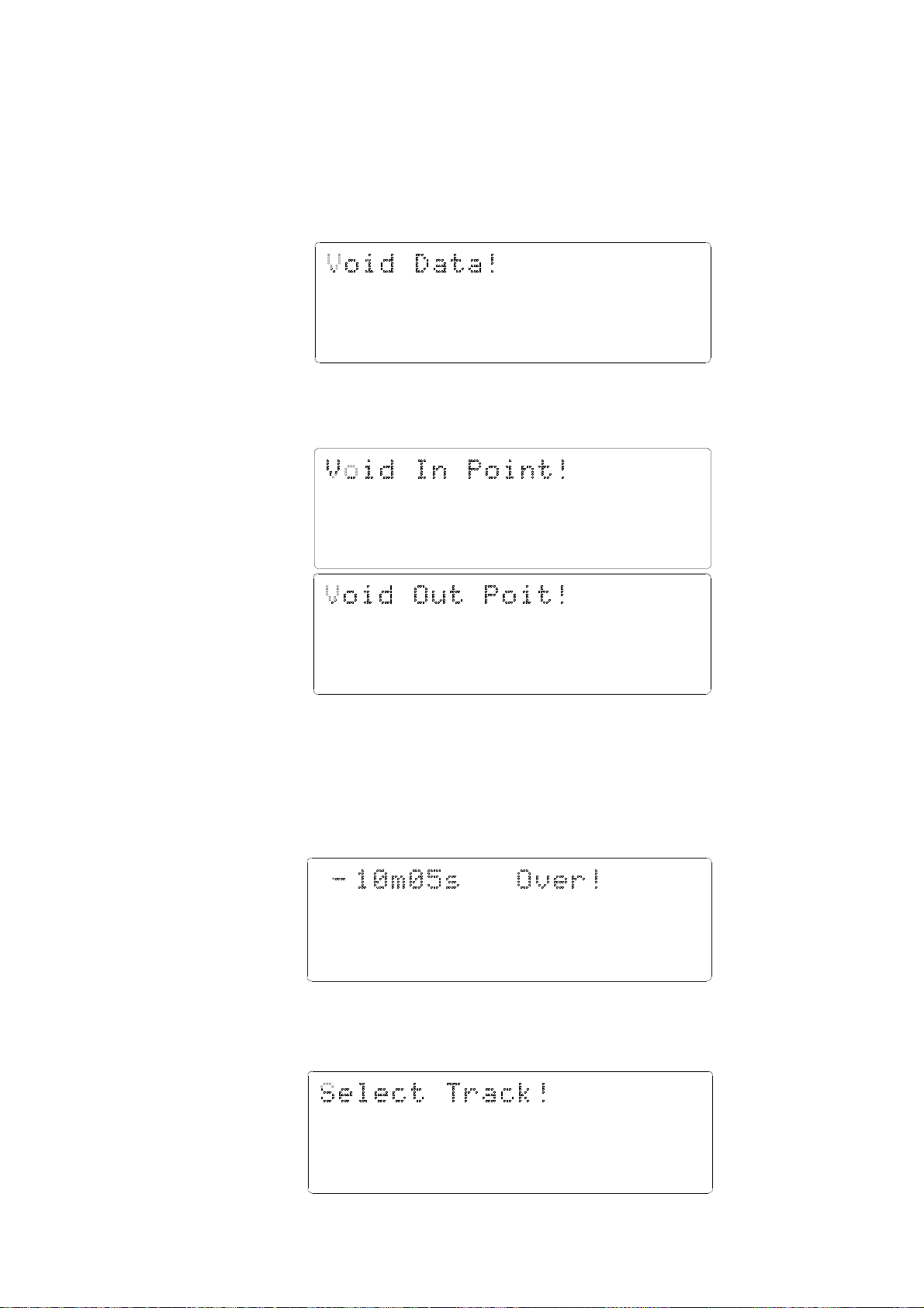
D-160 Owner's Manual (Names and Functions)
6. Warning messages
If you perform an incorrect operation, input incorrect data, or if an error occurs,
the following alarm indication appears:
Invalid data indication (The input data is not appropriate for the operation).
Action to take:
Input correct data.
OL
0
3
6
9
12
18
24
30
42
∞
_
Invalid In/Out indication (The In or Out point is not appropriate for the operation).
Action to take:
Input correct data.
OL
0
3
6
9
12
18
24
30
42
∞
_
91011121314151687654321
91011121314151687654321
OL
0
3
6
9
12
18
24
30
42
∞
_
91011121314151687654321
Overtime indication (Available disk space is insufficient for the length of time (the number
of measures) indicated on the display.)
Action to take:
During the copy & paste and move & paste operation, try to shorten the length
of the copied data by the indicated amount. Alternatively, use the "ERASE"
function to move the ABS END point backward to obtain enough disk space for
editing.
OL
0
3
6
9
12
18
24
30
42
∞
_
91011121314151687654321
Unassigned track indication (Select any track)
Action to take:
Use the RECORD TRACK select key to ready any track.
OL
0
3
6
9
12
18
24
30
42
∞
_
91011121314151687654321
29
Page 30
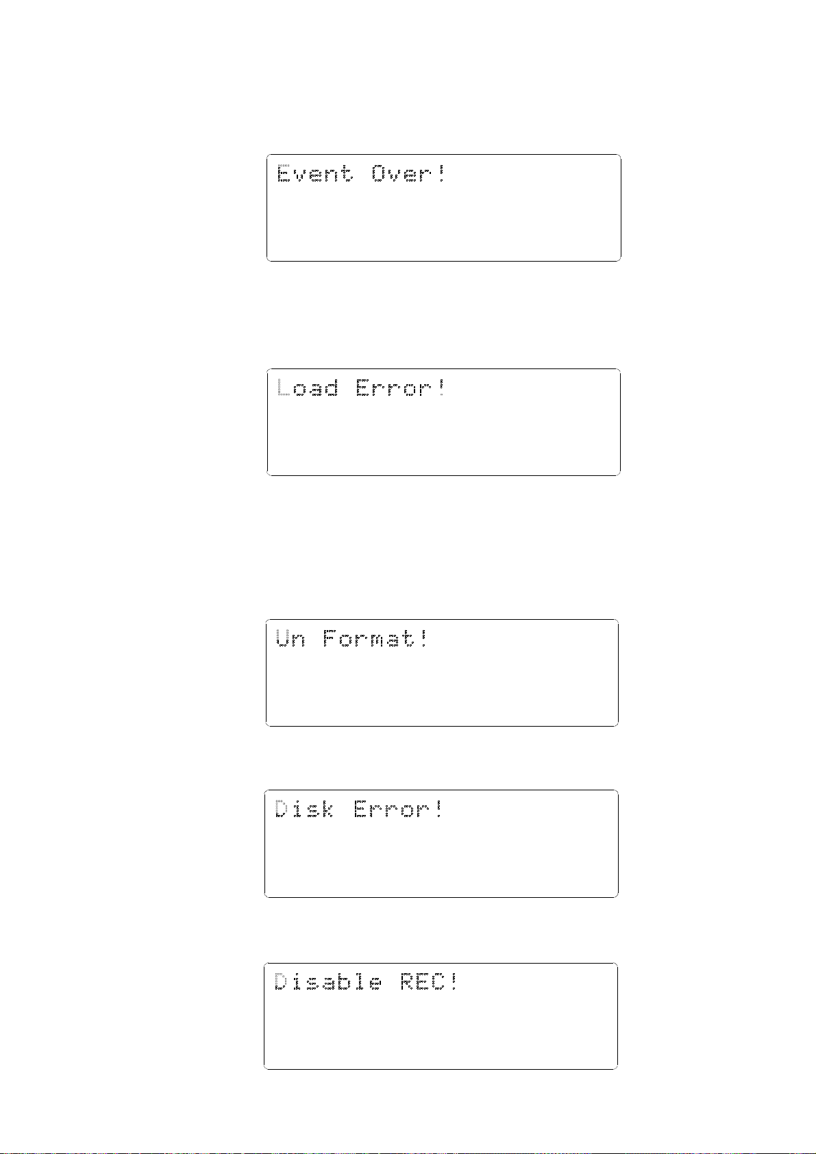
D-160 Owner's Manual (Names and Functions)
Event overflow indication (The editing points are overflowed)
Action to take:
You edited too much. The warning means "you cannot paste or erase any more."
In regards to event, refer to "Event and Audio File" in Before Operating section.
OL
0
3
6
9
12
18
24
30
42
∞
_
Load error indication (You cannot load data because the data input to the DATA INPUT
connector contains an error)
Action to take:
Check to see if there is an abnormality with the external digital machine
connected to the DATA INPUT connector, or cable. Try to "LOAD" again.
OL
0
3
6
9
12
18
24
30
42
∞
_
91011121314151687654321
91011121314151687654321
Un-formatted indication (The internal hard disk is damaged or not formatted yet.)
After this message is shown for about 10 seconds, "FORMAT" in Setup mode will
flash on the display. Pressing the EXECUTE/YES key at this moment will erase
all data and reformat the hard disk.
Action to take:
Press the EXECUTE/YES key to format the disk. (All audio and other data on the
disk will be lost.)
OL
0
3
6
9
12
18
24
30
42
∞
_
91011121314151687654321
Disk error indication (This disk cannot be read)
Action to take:
Contact the Fostex service station as soon as possible.
OL
0
3
6
9
12
18
24
30
42
∞
_
91011121314151687654321
Recording Disable (Recording is disabled.)
Action to take:
Change the "Off" (recording) "Rec Protect ?" setting in Setup mode.
OL
0
3
6
9
12
18
24
30
42
∞
_
91011121314151687654321
30
Page 31

D-160 Owner's Manual (Names and Functions)
SCSI device connection error: (The SCSI device is not connected correctly.)
Action to take:
Check to see if the external SCSI device is connected to the SCSI connector
correctly, or the power to the SCSI device is turned on.
OL
0
3
6
9
12
18
24
30
42
∞
_
Disk Lock error: (The hard disk is not installed correctly, or not securely locked by the key.)
Action to take:
Install the hard disk correctly or confirm that the disk is set properly, and be
sure to lock it using the included key.
OL
0
3
6
9
12
18
24
30
42
∞
_
91011121314151687654321
91011121314151687654321
In rare case, the "No Disk IDE" will also be displayed if the cartride connector
pins are soiled. In such a case, clean the connector pins with alcohol or its
equivalent.
When cleaning, however, be extremely careful not to generate static electricity.
SCSI save error: (Occurrence of an error during execution of save into SCSI equipment)
Action to take:
Because "Retry?" will be displayed when the EXIT/NO key is pressed, if save is to
be executed again, press the EXECUTE/YES key upon display of "Retry?."
If save is to be canceled at this stage, press the EXIT/NO key again.
OL
0
3
6
9
12
18
24
30
42
∞
_
91011121314151687654321
SCSI load error: (Occurrence of an error during execution of load from SCSI equipment)
Action to take:
Because "Retry?" will be displayed when the EXIT/NO key is pressed, if loading
is to be executed again, press the EXECUTE/YES key upon display of "Retry?."
If loading is to be canceled at this stage, press the EXIT/NO key again.
OL
0
3
6
9
12
18
24
30
42
∞
_
91011121314151687654321
31
Page 32

D-160 Owner's Manual (Before operating the D-160)
Before Operating the D-160
This section explains the following items that you should learn before you start operating
the D-160.
1. Hard disk recording method and the REMAIN display
2. Audio file and event
3. Program Change function
4. Real track and additional track
5. Input monitor and reproduction monitor
6. Time base
7. Installing and formatting a hard disk
8. Expanding a detachable controller
1. Hard disk recording method and the REMAIN display
The D-90, D-80, and DMT series are able to play back only within a recorded area (ABS 0
- ABS END), but unable to play or fast forward after the record end point (ABS END) as
shown in the diagram below. They can start recording only from the ABS END point.
ABS 0
D-90, D-80, and DMT series
ABS END
approx. 30 minutes
(when installing the Model 9041.)
Play is possible in this area.
ABS TIME: 00m 00s 00f ~ 30m 00s 00f
Non recorded area
On the other hand, the D-160 enables you to select any ABS time position within 24 hours
to record an audio signal on the formatted hard disk. (Refer to the diagram below.)
For example, if you are using an optional Model 9041 (1.3GB removable hard disk
cartridge), you can record about 15 minutes to all 16 tracks anywhere within the range of
24 hours. (The REMAIN display will indicate 240 minutes since the D-160 calculates the
remaining free space based on a mono track.)
ABS 0
Recorded area (5 minutes)
00h 05m
The D-160 enables you to select any ABS
time position within 24 hours to record an
10h 00m
Non recorded
area
Recorded area (5 minutes)
ABS time: within 24 hours
audio signal
10h 05m
ABS END
24h 00m
Non recorded area
If you recorded five minutes of 16-track data starting at 00h:00m:00s:00f:00sf (ABS 0),
then recorded another five minutes of data starting at 10h:00m:00s:00f:00sf, the ABS
END point would be at the end of the second recording, 10h:05m:00s:00f:00sf.
This does not mean that the recording on the hard disk is 10 hours 5 minutes long.
The total recorded time on the disk would be 10 minutes (two 5-minute recordings).
In this case, if you try to play the unrecorded area (00h:05m through 10h:00m), the
display will count down the time, but the D-160 will not access the hard disk.
The same applies to the area after the ABS END point. If you try to play or fast forward
in the area after the ABS END point, the display will count down to one frame before 24
hours (based on the frame rate specified in Setup mode).
However, MTC will be output during the playback of an unrecorded area.
In this example, pressing the DISP SEL key will switch to the REMAIN display that
indicates about 80 minutes (based on a mono track). This is a recordable duration when
data is recorded in a single track. As mentioned, above the REMAIN display will indicate
240 minutes when you are using an optional Model 9041 (1.3GB removable hard disk
32
Page 33

cartridge.) This means that you can record total 240 minutes of data with a sampling
rate of 44.1kHz in a single track.
Recording one-minute, one-track data with a sampling rate of 44.1kHz on the D-160
requires approximately 5.3MB of hard disk space. Therefore, the amount of space required
for a particular recording should be obtained by multiplying 5.3MB by the number of
tracks by the number of minutes (duration). If the REMAIN display indicates 240 minutes
based on a mono track, you can record about 15 minutes of 16-track data. If you have
recorded 10 minutes of 16-track data, you would have used the hard disk space
corresponding to 160 minutes (16 tracks times 10 minutes). The resultant REMAIN value
would be 240 -160 = 80 minutes.
2. Audio file and Event
As described in the previous section “Hard disk recording method and the REMAIN
display,” the basic recording method differs between the D-90/D-80/DMT series and D-
160. The D-160 contains sequential individual audio files recorded in the tracks of a
Program. You can insert silence between these audio files. The silence will be counted as
a zero file. As shown in the diagram below, audio files and zero (0) files will be recorded
alternately.
“The number of events” of a certain track is calculated by adding up the number of these
audio files and zero files. Each track can contain up to 512 events, but the D-160 will not
record new data when the recording reaches the event 508.
ABS 0
Audio File 1
D-160 Owner's Manual (Before operating the D-160)
ABS END
Audio File 2 0 File 1 Audio File 3
0 File 2
Audio File 4
No sound
No sound
Usually, a single event is created by one recording or editing operation, and the number
of the events changes according to the edit point or the amount of available disk space.
(The D-160’s disk management generally tries to reduce the number of events.)
This does not create problems in most music production. However, if you make frequent
recordings with zero files in between the audio files, the number of the events could
exceed the limit. In order to prevent this, you need frequently to check the number of
events on each track during a session.
Use the “NOs Of Event?” menu in Setup mode to check the number. Refer to “‘NOs Of
Event?’ menu in Setup mode” on page "163."
<Note on Digital In recording>
No “0 file” is created during analog recording, because data 0 will not continue even when
silence is being recorded. On the other hand, if you are recording data via S/P DIF or adat
input, the D-160 will create a zero file when 0 data is consecutively input for one second to
save disk space. This increases the number of events. Watch out for “the excessive number
of events.”
What is an event?
As shown in the diagram below, the number of events can be eleven or more if partial
recordings are made. This is because an unrecorded part is regarded as an event, and a
recorded part is also regarded as an event(s). The duration of each event can vary from
740 msec to 23 hours 59 minutes 59 seconds (FS = 44.1kHz).
ABS 0
Recorded part (shortest: 740 msec, FS=44.1kHz)
Unrecorded part (shortest: 740 msec, FS=44.1kHz)
0
14 910
23 567 8 11
33
ABS 23h 59m
ABS END
Page 34

D-160 Owner's Manual (Before operating the D-160)
An unrecorded part (zero file) is always regarded as one event, regardless of its duration.
However, a recorded part can consist of a group of multiple audio files, as shown in the
diagram below.
More precisely, one audio file will be divided into multiple audio files if perform many
editing operations (such as, copy & paste, move & paste, etc.) on this audio file. Multiple
audio files created in this way are regarded as events. (If you do not edit the data at all,
the audio file remains in one piece and is regarded as one event.)
In this example, one recorded area consists of six consecutive audio files. This means that
this part consists of six events.
Recorded Area
0 File
Event Number
Audio File 1 Audio File 2 Audio File 3 Audio File 4
n + 3n + 2n + 1
n + 4
Audio File 5 Audio File 6
n + 5
n + 6
0 File
This is because when you perform a copy & paste, move & paste, or Auto Punch In/Out,
the event is split at the edit point. Also, if a continuous long recording is made, the
recorded data might scatter to different locations on the hard disk, thus dividing the data
into multiple events.
Clipboard In Point
0 File
Audio File 1 Audio File 2 Audio File 3 Audio File 4
n + 1
n + 2 n + 3
n + 4
Audio File 5 Audio File 6
n + 5
n + 6
Clipboard Out Point
0 File
Countermeasures against accumulating too many events due to a long recording plus
many editing operations:
One solution is to save and re-load the data to and from a DAT, Adat, or SCSI device. (If
the song is too long, you may not be able to save the data to a DAT or Adat.)
In this way, multiple consecutive audio files are optimized into one continuous audio file
in some cases.
If you know which part of the data you edited, and if the hard disk has enough free space,
you can use another solution in some cases.
Set the Clipboard In point and the Clipboard Out points within an unrecorded range to
copy the area (the area that contains multiple audio files and you wish to optimize)
between them, then paste the data starting from the same Clipboard In point.
Multiple audio files within this range will become a single audio file.
<Hint>
Make sure that you set the Clipboard In/Out points within zero files, and that you paste
the area starting from the SAME Clipboard In point.
* In any case, bear in mind that you cannot reduce the excessive number of events if the
target range contains a zero file.
34
Page 35

D-160 Owner's Manual (Before operating the D-160)
3. Program Change function
The D-160 features a Program Change function, which enables you to setup as many as
99 Programs on a single hard disk, and record and edit up to 99 separate songs.
You can also name (title) each Program.
Using an analogy, imagine that each Program has its own room on the hard disk.
You can record, play, and edit each Program without affecting other Programs.
Assume that you have made a six-minute mono-track recording in Program 1, then you
have setup Program 2 and made a 10-minute, mono-track recording to the Program.
Now, the hard disk contains two rooms (total 16 minutes). (You can setup a maximum of
99 Programs.)
Program 1
Program 5
Program 9
Program 2
Program 6 Program 7
Program 10 Program 11
Individual rooms (You can setup a maximum of 99 Programs.)
Program 3
Program 4
Program 8
Program 12
In the default setting, one Program has been setup. If you wish to setup more Programs,
refer to “Recording/Playback, 2-1. Setting up a Program.”
Please remember, however, that regardless of the number of Programs you setup, the
total recording time of the Programs cannot exceed the maximum available time of the
hard disk.
For example, if you are using a Model 9041 (1.3GB), you can record up to about 15
minutes on all 16 tracks (with a sampling rate of 44.1kHz), or up to 240 minutes on a
single mono track. Therefore, if you have already recorded a 15-minute, 16-track song in
Program 1, the available recording time will remain 0, and you will be unable to record
data to other Programs.
35
Page 36

D-160 Owner's Manual (Before operating the D-160)
4. Real track and additional track
You can record, play back, and edit up to 16 real tracks on the D-160.
The D-160 also features eight additional tracks.
Real tracks 1-16 are used for recording, playing back, and editing.
Additional tracks 17-24 are used to store data.
More precisely, you can play back and monitor data recorded on the real tracks and
check it with the level meters. But, data stored on the additional tracks cannot be
monitored or checked with the level meters. The purpose of the additional tracks is to
temporarily store the data recorded on the real tracks (1-16).
Track 16
Track 15
Track 14
Track 13
Track 12
Track 11
Track 10
Track 9
Track 8
Track 7
Track 6
Track 5
Track 4
Track 3
Track 2
Track 1
Example:
Exchange data recorded on Track 11 with data recorded on Track 15.
Example:
Swapping between real
tracks 1-8 (or 9-16) and
additional tracks 17-24.
Track 24
Track 23
Track 22
Track 21
Track 20
Track 19
Track 18
Track 17
Real track
Additional track
You can swap data between two tracks (between two real tracks, additional tracks, or
between a real track and a additional track) using the “Track Exchange?” menu in the
Setup mode.
For example, you can exchange data recorded on Track 1 with data recorded on Track 8.
If you swap between a track with data and a track without data, the track that originally
contained data will become empty.
You can also swap data between eight tracks; that is, swapping between real tracks 1-8 (or
9-16) and additional tracks 17-24.)
This is very convenient in a multitrack recording application when you wish to clear
some tracks in order to make new recordings.
For example, if you swap between real tracks 1-8 (or 9-16) with data and additional
tracks 17-24 without data, the real tracks become empty. So, you can make new recordings
in these empty tracks. You can, of course, load back the data from the additional tracks
to real tracks. During the save/load operation, you can also save or load both real track
data and additional track data.
<Notes>
* The D-160 always uses data on real tracks for the ABS END indication.
For example, If you have moved all track data to the additional tracks and the real tracks are empty, ABS END
is “0.” In order to check the ABS END point of the data in the additional tracks, you need to move the data into
the real tracks. Alternatively, you can check the data status of the additional tracks by checking the events on
the “NOs Of Event?” menu in Setup mode. (Refer to page "163" for more information on the “NOs Of Event?”
menu in Setup mode.)
* You cannot swap data between the tracks from two different Programs.
36
Page 37

D-160 Owner's Manual (Before operating the D-160)
5. Input monitor and Repro monitor
There are two ways to monitor track data on the recorder: Input monitor and
Repro monitor. These are defined as follows:
Input monitor:
Input monitoring enables you to listen to the input signal that is routed to
and output through the tracks just as it is. That is, listening to (monitoring)
the post-recorder input signal (not the pre recorder signal).
Sixteen tracks on the D-160 can be set to either "Input monitoring" or "
Repro monitoring" status. Follow the steps below to set the tracks to Input
monitor.
1. Set the track to recording status.
To set the track to recording status, first ready the track, then press the PLAY button while
holding the RECORD button. The recording track will be in Input monitoring status.
Alternatively,
2. Ready the track, and press the RECORD button once. (If you press the RECORD
button again, the track enters the repro monitoring status.)
16
15
14
13
12
11
10
9
8
7
6
5
Input signals
Mixer
4
3
2
1
Mixer
Recorder (D-160)
* The RECORD LED next to the RECORD button will flash, and the currently selected
tracks will enter input monitoring status.
Repro monitor:
Repro monitoring enables you to monitor the playback signal on the tracks;
that is, to listen to the output of the recorded signal.
Track 5:
INPUT monitor
Tracks 1-4:
REPRO monitor
16
15
14
13
12
11
10
9
8
7
6
5
4
3
2
1
Recorder (D-160)
37
Mixer
All tracks:
REPRO monitor
Page 38

D-160 Owner's Manual (Before operating the D-160)
6. Time Base
The D-160 indicates the location of the recorder (the current position) using
the ABS time, MTC, or MIDI Bar/Beat/Clock. This time reference is called "Time
Base."
ABS (Absolute Time) refers to an absolute time on the hard disk; MTC (MIDI
timecode) refers to a relative time obtained by adding a certain value (MTC
offset value) to the ABS value; and BAR/BEAT/CLK (bar/
position in a song that corresponds to the MIDI Clock/Song Position pointer and
can be created using the internal Tempo Map. (The following diagram shows
the relationship between the three types of time base.)
* Replace all symbols in the text with the quarter note symbol.
/clock) indicates a
ABS
BAR/
BAR =001BAR, "0404(4/4)"
TEMPO=001BAR, 1 "60( =60)"
/CLK
MTC
MTC OFFSET=01h, 00m, 00s, 00f
MTC OFFSET MODE = ABS
(THIS shall be assumed to be the
MTC OFFSET time set for the ABS
00m, 00s and 00f positions.)
ABS 0
00m, 00s, 00f
○○○○○○○○○○○○○○○○○○○○○○○○○○○○○○○○○○○○○○○○○○○○○○○○○○○○○○○○○○○
-002BAR, 1 , 00 CLK
01h, 00m, 00s, 00f
00m, 08s, 00f
○○○○○○○○○○○○○○○○○○○○○○○○○○○○○○○○○○○○○○○○○○○○○○○○○○○○○○○○○
001BAR, 1 , 00 CLK
01h, 00m, 08s, 00f
ABS END
○○○○○○○○○○○○○○○○○○○○○○○○○○○○○○○○○○○○○○○○○○○○○○○○○○○○○○○○○○○○
DISK END
23h 59m 59s
○○○○○○○○○○○○○○○○○○○○○○○○○○○○○○○○○○○○○○○○○○○○○○○○○○○○○○○○○○○
0h 59m 59s
MTC
MTC OFFSET=01h, 00m, 00s, 00f
MTC OFFSET MODE = BAR
(THIS shall be assumed to be the
MTC OFFSET time set for the 00
BAR, 1 and 00 CLK positions.)
00h, 59m, 52s, 00sf
01h, 00m, 00s, 00sf
Recorded area
38
0h 59m 51s
Non recorded area
Page 39

D-160 Owner's Manual (Before operating the D-160)
7. Installing and formatting a hard disk
The D-160 utilizes a removable hard disk cartridge, making it quick and
easy to transport and replace the hard disk.
Using an optional removable hard disk cartridge Model 9041 (1.3GB hard
disk built-in) or Model 9040B (empty caddy without hard disk) allows you
to replace the cartridge or extend the sixteen tracks recording time very
easily.
* Refer to next page for more information on replacing the removable hard disk cartridge.
You can install an ATA (IDE) standard hard disk in an optional removable case
Model 9040B (without hard disk).
<Note>
Refer to the "Supplement" for more information on "Recommended Hard Disk" and
"Operation-Confirmed hard Disk" lists.
<WARNING>
Plug the included dust cap onto the connector of the D-160's removable hard disk to
protect the disk from static electricity, dust and dirt before you store or transport the
hard disk. A hard disk is precision device. Handle it with care and avoid vibration,
humidity, strong magnetic fields, static electricity, dust, etc. In particular, do not touch
the connector with your hands to protect the hard disk from static electricity.
Removable hard disk
Plug the dust cap onto the connector.
(Do not touch the connector with your hands.)
39
Page 40

D-160 Owner's Manual (Before operating the D-160)
Installing a removable hard disk cartridge
A hard disk cartridge is not installed in the D-160 when it is shipped. You will need
to install a removable hard disk cartridge in the D-160. (You can use an optional
Model 9041 or a hard disk that has been approved for performance and installed
in the removable case that came with the D-160.)
Follow the procedure below to install a new hard disk cartridge. Be sure to format
the hard disk. The following procedure should be performed with the power to the
D-160 turned off.
1. Remove the blank panel from the cartridge slot.
POWER
<CAUTION>
Do not try to insert your fingers into the removable
hard disk cartridge drive after the cartridge has
been removed. Otherwise, electric shock or
unexpected injury could result.
2. Insert the hard disk cartridge (e.g., Model 9041) into the slot.
Make sure that you insert the cartridge until it clicks into place. Be sure to remove the
dust cap on the connector of the cartridge case before inserting the cartridge.
POWER
Model 9041
DIGITAL MULTITRACK RECORDER
DIGITAL MULTITRACK RECORDER
D-160
Blank panel
D-160
The unit is
shipped from
the factory
with the lock
on the right
1
Unlock
of the slot
released.
2
3. Lock the cartridge with the key included in the package.
DIGITAL MULTITRACK RECORDER
POWER
D-160
3
Lock
4. Connect the connector of the detachable controller, and install the controller to the D-160.
AUTO RTN
CLIPBOARD
REHEARSAL
TAKE
CLIPBOARD PLAY
LOCATE ABS 0
LOCATE ABS END
PASTEMOVECOPY
AUTO PUNCH
AUTO RTN
ERASE UNDO REDO
LOCATEPUNCH
4
POWER
PUNCH
IN / OUT
DIGITAL MULTITRACK RECORDER
RECORD TRACK
HD ACCESSLOCKED MTC IN
D-160
8/167/156/145/134/123/112/101/9
AUTO PLAY IN OUT
AUTO
SHIFT
VARI PITCH
ENDIN OUTSTART
F FWDREWINDPLAYSTOPRECORD
EXECUTE
DISP SEL
/YES
TIME BASE SEL
HOLD/ STORE RECALL
PGM CHANGE
EXIT
/NO
* When installation is completed, follow the procedure “Formatting a hard disk” on
page "43" to format the hard disk.
* If you are using a hard disk (that has been approved for performance) and installing
it in the removable case that came in the package, refer to “Installing a hard disk in the
removable case” on page "42."
40
Page 41

D-160 Owner's Manual (Before operating the D-160)
Replacing a removable hard disk cartridge
Follow the procedure below to replace the removable hard disk cartridge.
1. Turn the power off to the D-160.
AUTO RTN
AUTO PUNCH
DIGITAL MULTITRACK RECORDER
RECORD TRACK
HD ACCESSLOCKED MTC IN
D-160
8/167/156/145/134/123/112/101/9
2
1
POWER
PUNCH
IN / OUT
CLIPBOARD
AUTO PLAY IN OUT
PASTEMOVECOPY
ERASE UNDO REDO
AUTO
REHEARSAL
LOCATEPUNCH
TAKE
SHIFT
CLIPBOARD PLAY
LOCATE ABS 0
LOCATE ABS END
EXECUTE
EXIT
ENDIN OUTSTART
DISP SEL
/YES
TIME BASE SEL
HOLD/ STORE RECALL
PGM CHANGE
/NO
AUTO RTN
VARI PITCH
F FWDREWINDPLAYSTOPRECORD
2
2. Remove the connector from the detachable remote controller section, and remove the
controller section.
3. Release the lock using the key included in the package. (Refer to the figure on the right
below.)
POWER
<CAUTION>
Do not try to insert your fingers into the removable
hard disk cartridge drive after the cartridge has
been removed. Otherwise, an electric shock or
unexpected injury may result.
4. Pull the disk cartridge forward you to remove it.
The hard disk is a precision device. Handle it with care.
PUNCH
IN / OUT
DIGITAL MULTITRACK RECORDER
D-160
DIGITAL MULTITRACK RECORDER
RECORD TRACK
HD ACCESSLOCKED MTC IN
D-160
8/167/156/145/134/123/112/101/9
AUTO RTN
AUTO PLAY IN OUT
AUTO
SHIFT
REHEARSAL
TAKE
CLIPBOARD
CLIPBOARD PLAY
LOCATE ABS END
LOCATE ABS 0
PASTEMOVECOPY
AUTO PUNCH
AUTO RTN
ERASE UNDO REDO
LOCATEPUNCH
VARI PITCH
F FWDREWINDPLAYSTOPRECORD
ENDIN OUTSTART
EXECUTE
DISP SEL
/YES
TIME BASE SEL
HOLD/ STORE RECALL
PGM CHANGE
EXIT
/NO
3
Lock
Unlock
4
5. Insert new disk cartridge.
Gently push it in until a click noise is heard.
6. Lock the cartridge using the key. (Refer to the figure on the right above.)
7. Install the controller section, and fix the connectors securely using the screws.
DIGITAL MULTITRACK RECORDER
POWER
D-160
6
5
* When installation is complete, follow the procedure “Formatting a hard disk” on
page "43" to format the hard disk.
41
Page 42

D-160 Owner's Manual (Before operating the D-160)
8
8
Installing a hard disk in the Model 9040B removable case
If you have purchased one of the hard disks listed in the "Supplement," you need to
install the disk in the included removable case or Model 9040B optional removable case.
Follow the procedure below to install the disk in the removable case, and then
install the case in the D-160 as explained on the previous page, and format the disk.
<WARNING>
A hard disk consists of precision parts, and is sensitive to strong shocks (such as being dropped).
Handle the disk with care. Install the disk on a level, stable surface.
Fostex is not responsible for any malfunction or damage caused by incorrect handling.
<CAUTION>
If any part of the disk unit touches the case bottom, paste an "insulation seal (diameter: 18mm)"
included in the package of the case at the point of contact.
Some disk units may have such a dimension that the part could touch the case. If you use a
disk with a part touching the case, a short circuit, malfunction, or damage could result. Make
sure that no part of the disk touches the case, or paste the seal.
<Note>
Be sure to set the DIP switch or the JUMPER switch on the hard disk to "MASTER" when you
install the hard disk in the removable case. The disk will not operate if the setting is "
(Refer to Hard Disk's Owner's Manual for details.)
SLAVE."
1. Disassemble the removable case.
Refer to the diagram to remove the bottom of the case.
Hold down the case
with your hand.
Model 9040B
Place your figures on the upper part of the case, and
remove the bottom so that it will open in the direction of
the arrow.
Remove
Bottom
2. Insert the disk unit into the case, and connect the cable connectors on the case to the
appropriate connectors on the disk unit.
<Note on connecting the connector>
Sometimes it may be difficult or awkward, due to a lack of space, to connect the connectors
when you are installing a hard disk into the removable case. In this event, do not apply
excessive force on the connector. Use caution to avoid injury or damage to the hard disk.
Connect the cable
connector
Connector
Handle
234567
234567
42
Page 43

D-160 Owner's Manual (Before operating the D-160)
3. Secure the disk unit using the screws that come with the removable case. (Use two
screws on each side as shown in the diagram.)
Screws (x4)
4. Replace the bottom. (Before installation, read the following note.)
5. Install the entire case and disk in the D-160 following the steps on page “40” (don't
forget to lock the key!) and proceed to formatting.
Formatting a hard disk
After replacing the hard disk cartridge, follow this procedure to format the disk.
When you turn the power on to a D-160 that has an unformatted disk, the unit
automatically enters the Setup mode "Disk Format?" menu.
1. Confirm that the cartridge is locked by the key, and turn on the power to the D-160.
The display will show the initial screen, then change to the following screen:
"IDE" shown in the display indicates that the internal IDE hard disk is undergoing formatting.
OL
0
3
6
9
12
18
24
30
42
∞
_
91011121314151687654321
OL
0
3
6
9
12
18
24
30
42
∞
_
OL
0
3
6
9
12
18
24
30
42
∞
_
91011121314151687654321
SETUP
FORMAT
44.1kHz
91011121314151687654321
2. After confirming the above display, press the EXECUTE/YES key.
The currently installed internal IDE hard disk model name will be shown in the display
and "SURE?" will blink at the same time.
SETUP
OL
0
3
6
9
12
18
24
30
42
∞
_
91011121314151687654321
44.1kHz
FORMAT
SURE
?
3. Press the EXECUTE/YES key again.
Formatting of the internal IDE hard disk will be started and progressive to this, the
remaining unformatted disk capacity will be counted down attached with a minus symbol.
Simultaneous with the start of formatting, the ∞ symbol FL tube in the level meters of all
channels will light. And as formatting progresses, the FL tube will be extinguished one by
one starting from track 16.
This is an indication that the hard disk is being formatted correctly and when formatting
is finished, all FL tubes will be extinguish and "COMPLETED!" will be lit.
SETUP
OL
0
3
6
9
12
18
24
30
42
∞
_
91011121314151687654321
REMAIN
44.1kHz
FORMAT
OL
0
3
6
9
12
18
24
30
42
∞
_
SETUP
FORMAT
44.1kHz
!
COMPLETED
91011121314151687654321
4. Press the EXIT/NO key or the STOP button to quit Setup mode.
43
Page 44

D-160 Owner's Manual (Before operating the D-160)
9
* If you are using a hard disk that already contains any data from when it was used
in a computer, the D-160 may not enter formatting mode automatically. In this
case, press the DISP SEL key to force the unit to enter Setup mode, and then
select “Disk Format?” to format the disk. (See page “171” for more information on
“Disk Format?” menu in the Setup mode.)
8. Extending the detachable controller
You can remove the detachable controller from the main unit and extend
it using an optional Model 8551 extension cable.
This optional cable is five meters long, and is equipped with D-sub 15-pin
male and female connectors.
2345678
Connect to D-160 (male)
Connect to controller (female)
1. Turn the power off to the D-160 before connecting the cable.
2. Loosen the screw for the connector that connects the controller to the D-160,
and remove the connector.
3. Remove the controller from the D-160.
Pull the controller toward you while pushing it up with your hand to remove it easily.
2
1
POWER
PUNCH
IN / OUT
DIGITAL MULTITRACK RECORDER
RECORD TRACK
HD ACCESSLOCKED MTC IN
D-160
8/167/156/145/134/123/112/101/9
AUTO RTN
AUTO PLAY IN OUT
SHIFT
AUTO PUNCH
CLIPBOARD
PASTEMOVECOPY
ERASE UNDO REDO
AUTO
REHEARSAL
LOCATEPUNCH
TAKE
CLIPBOARD PLAY
LOCATE ABS 0
LOCATE ABS END
EXECUTE
EXIT
ENDIN OUTSTART
DISP SEL
/YES
TIME BASE SEL
HOLD/ STORE RECALL
PGM CHANGE
/NO
AUTO RTN
VARI PITCH
F FWDREWINDPLAYSTOPRECORD
3
DIGITAL MULTITRACK RECORDER
PUNCH
IN / OUT
RECORD TRACK
HD ACCESSLOCKED MTC IN
D-160
8/167/156/145/134/123/112/101/9
AUTO RTN
AUTO PLAY IN OUT
AUTO
SHIFT
REHEARSAL
TAKE
CLIPBOARD
CLIPBOARD PLAY
LOCATE ABS END
LOCATE ABS 0
PASTEMOVECOPY
AUTO PUNCH
AUTO RTN
ERASE UNDO REDO
LOCATEPUNCH
VARI PITCH
ENDIN OUTSTART
F FWDREWINDPLAYSTOPRECORD
EXECUTE
DISP SEL
/YES
TIME BASE SEL
HOLD/ STORE RECALL
PGM CHANGE
EXIT
/NO
4. Insert the male connector of the extension cable to the D-160's connector, and
secure it with a screw.
5. Connect the female connector on the cable and the male connector on the
controller cable, and secure them with a screw.
44
Page 45

D-160 Owner's Manual (Before operating the D-160)
POWER
D-160
DIGITAL MULTITRACK RECORDER
4
5
DIGITAL MULTITRACK RECORDER
PUNCH
IN / OUT
RECORD TRACK
HD ACCESSLOCKED MTC IN
D-160
8/167/156/145/134/123/112/101/9
AUTO RTN
AUTO PLAY IN OUT
AUTO
SHIFT
REHEARSAL
TAKE
CLIPBOARD
CLIPBOARD PLAY
LOCATE ABS 0
LOCATE ABS END
PASTEMOVECOPY
AUTO PUNCH
AUTO RTN
ERASE UNDO REDO
LOCATEPUNCH
VARI PITCH
F FWDREWINDPLAYSTOPRECORD
ENDIN OUTSTART
DISP SEL
HOLD/ STORE RECALL
TIME BASE SEL
PGM CHANGE
EXECUTE
EXIT
/YES
/NO
6. Turn the power on to the D-160, and operate the buttons and keys on the
controller to confirm that the D-160 operates correctly.
<WARNING>
When you use the detachable controller remotely using an extension cable, the D160 may malfunction due to electromagnetic interference. In this case, turn the power
off, then on to the D-160 to restore it to normal.
Fostex is not responsible for any malfunction of the D-160 that is caused by
electromagnetic interference.
<CAUTION>
Turn off the D-160 before connecting or disconnecting any cables.
Connecting or disconnecting the footswitch or detachable controller cables while the
D-160 is turned on will cause it to malfunction.
45
Page 46

D-160 Owner's Manual (Recording /Playback)
3
3
3
3
3
3
3
3
3
3
3
3
3
3
3
3
3
3
3
3
3
3
3
3
3
3
3
3
3
3
3
3
3
3
3
3
123
123
123
123
123
123
123
123
123
123
123
3
3
3
3
3
3
3
3
3
3
3
3
3
3
3
3
3
3
3
3
3
3
3
3
3
3
3
3
3
3
3
3
3
3
3
3
Recording / Playback
This section explains how to record and playback data on the D-160.
1. Basic connections
The D-160 is a 16-track recorder, equipped with analog INPUTs 1-8 and OUTPUTs
1-16. Refer to the following diagram to connect the D-160 to an external mixing
console or multitrack recording.
The optimum mixing console for the D-160 would be equipped with 16 TAPE IN
connectors and 8 BUSS OUT connectors (or GROUP OUT connectors), although you
can also use a mixer with 16 TAPE IN connectors and 4 BUSS OUT connectors.
Refer to the following examples depending on the type of your mixer.
<Example-1>
Connecting a mixer equipped with 16 TAPE IN, 8 BUSS OUT (or GROUP OUT):
This connection allows for 8-track simultaneous recording.
* Connect the mixer TAPE IN 1-16 with the D-160 OUTPUT 1-16.
* Connect the mixer BUSS OUT (or GROUP OUT) 1-8 with the D-160 INPUT 1-8.
D-160
AUTO RTN
DIGITAL MULTITRACK RECORDER
POWER
PUNCH
IN / OUT
RECORD TRACK
HD ACCESSLOCKED MTC IN
D-160
8/167/156/145/134/123/112/101/9
SHIFT
CLIPBOARD
AUTO PLAY IN OUT
AUTO
REHEARSAL
TAKE
OUTPUT 1 - 16
CLIPBOARD PLAY
LOCATE ABS 0
LOCATE ABS END
PASTEMOVECOPY
AUTO PUNCH
AUTO RTN
ERASE UNDO REDO
LOCATEPUNCH
VARI PITCH
F FWDREWINDPLAYSTOPRECORD
DISP SEL
ENDIN OUTSTART
HOLD/ STORE RECALL
TIME BASE SEL
PGM CHANGE
EXECUTE
EXIT
/YES
/NO
INPUT 1 - 8
BUSS OUT
TAPE IN 1 - 16
2
2
2
2
2
2
2
2
2
2
2
2
2
2
2
2
2
2
2
2
2
2
2
2
2
2
2
2
2
2
2
2
2
2
2
2
2
2
2
2
2
2
2
2
2
(GROUP OUT) 1 - 8
2
2
2
2
2
2
2
2
2
2
2
2
2
2
2
2
2
2
2
2
2
2
2
2
2
2
2
INPUT
External Mixer
Input signals (Guitar, Keyboard or Vocal etc.)
46
Page 47

D-160 Owner's Manual (Recording /Playback)
3
3
3
3
3
3
3
3
3
3
3
3
3
3
3
3
3
3
3
3
3
3
3
3
3
3
3
3
3
3
3
3
3
3
3
3
3
3
3
3
3
3
3
3
3
3
3
3
3
3
3
3
3
3
3
3
3
3
3
3
3
3
3
3
3
3
3
3
3
3
3
3
3
3
3
3
3
3
3
3
3
<Example-2>
Connecting a mixer equipped with 16 TAPE IN, 4 BUSS OUT (or GROUP OUT):
In this example, you would record tracks 1-4 first, then tracks 5-8, 9-12 or 13-16.
* Connect the mixer TAPE IN 1-16 with the D-160 OUTPUT 1-16.
* Connect the mixer BUSS OUT (or GROUP OUT) 1-4 with the D-160 INPUT 1-4 to record
tracks 1-4. To record tracks 5-8 and 13-16, connect INPUT 5-8 instead of INPUT 1-4.
(Using a patch bay allows you to change the connection from the front.)
D-160
AUTO RTN
DIGITAL MULTITRACK RECORDER
POWER
PUNCH
IN / OUT
RECORD TRACK
HD ACCESSLOCKED MTC IN
D-160
8/167/156/145/134/123/112/101/9
SHIFT
CLIPBOARD
AUTO PLAY IN OUT
AUTO
REHEARSAL
TAKE
OUTPUT 1 - 16
CLIPBOARD PLAY
LOCATE ABS 0
LOCATE ABS END
PASTEMOVECOPY
AUTO PUNCH
AUTO RTN
ERASE UNDO REDO
LOCATEPUNCH
VARI PITCH
F FWDREWINDPLAYSTOPRECORD
ENDIN OUTSTART
DISP SEL
HOLD/ STORE RECALL
TIME BASE SEL
PGM CHANGE
EXECUTE
EXIT
/YES
/NO
INPUT 1 - 8
Patch bay
TAPE IN 1 - 16
BUSS OUT (GROUP OUT) 1 - 4
2
2
2
2
2
2
2
2
2
2
2
2
2
2
2
2
2
2
2
2
2
2
2
2
2
2
2
2
2
2
2
2
2
2
2
2
2
2
2
2
2
2
2
2
2
2
2
2
2
2
2
2
2
2
2
2
2
2
2
2
2
2
2
2
2
2
2
2
2
2
2
2
2
2
2
2
2
2
2
2
2
INPUT
External Mixer
Input signals (Guitar, Keyboard or Vocal etc.)
47
Page 48

D-160 Owner's Manual (Recording /Playback)
2. Default setting on the D-160
Before you start operating the D-160 or proceed to the next step, you may want to
arrange the controls and switches to restore the initial setting so that you will not,
for example, erase important data on a track by using incorrect settings.
In this manual, this procedure is called "setting defaults." For default settings, the
controls and switches should be arranged as shown in the figure below.
Make it a rule to return to these default settings before you proceed to a new step.
* "FORMAT FIRST". You need to format the internal hard disk prior to start recording
if a brand new hard disk drive has been installed. Refer to the explanation of the
"Disk Format?" menu in the Setup mode. We recommend that you format the hard
disk as often as possible before you start fresh recording on it.
However, remember that the format process will erase all of the recorded song
data.
Outline of the Initial Settings:
* Turn all the RECORD TRACK select keys to "SAFE." (Track indication is turned off.)
* Auto Return/Auto Play mode is "OFF." (The AUTO RTN/AUTO PLAY LEDs are off.)
* Auto Punch mode is "OFF." (The REHEARSAL/TAKE LEDs are off.)
* The STOP button LED is lit.
* The STORE key and the RECALL keys are "OFF." (The STORE/RECALL LEDs are off.)
* "Rec Protect?" is "Off" selected in Setup mode.
* "Digi. In?" is assigned to "L: - -, R: - -" in Setup mode.
* "Slave Mode?" is "Off" selected in Setup mode.
* Setting a Program for recording/playback (See 2-1, 2-2, 2-3.)
* Setting a sampling rate for recording/playback (See 2-4.)
* Turning off the Vari-pitch function. (The LED is turned off.)
* The LED of the SHIFT key is off.
When the Recording Enabled/Disabled parameter in the Setup mode is set to "DISABLE
rEc," pressing the RECORD button and the PLAY button will not start recording, and
the unit will display "DISABLE rEc" on the panel. Be sure to set the mode to "EnAbLE
rEc" to enable the recording function.
Auto Return/Auto Play mode is "OFF." (The
AUTO RTN/AUTO PLAY LEDs are off.)
The display Time Base is set to ABS
TIME, and Program P1 is selected.
DIGITAL MULTITRACK RECORDER
POWER
PUNCH
IN / OUT
Turn all the RECORD TRACK
select keys to "SAFE." (Track
indication is turned off.)
RECORD TRACK
HD ACCESSLOCKED MTC IN
D-160
8/167/156/145/134/123/112/101/9
SHIFT
AUTO RTN
CLIPBOARD
AUTO PLAY IN OUT
AUTO
REHEARSAL
TAKE
CLIPBOARD PLAY
LOCATE ABS 0
LOCATE ABS END
Auto Punch mode is "OFF." (The
REHEARSAL/TAKE LEDs are off.)
The STORE key and the
RECALL keys are "OFF." (The
STORE/RECALL LEDs are off.)
PASTEMOVECOPY
AUTO PUNCH
AUTO RTN
ERASE UNDO REDO
LOCATEPUNCH
VARI PITCH
F FWDREWINDPLAYSTOPRECORD
ENDIN OUTSTART
EXECUTE
DISP SEL
/YES
TIME BASE SEL
HOLD/ STORE RECALL
PGM CHANGE
EXIT
/NO
Turning off the Vari-pitch function.
(The LED is turned off.)
The LED of the SHIFT key is off.
48
The STOP button LED is lit.
Page 49

2-1. Setting a Program
1
EXECUTE
DISP SEL
TIME BASE SEL
HOLD/ STORE RECALL
PGM CHANGE
EXIT
/YES
/NO
D-160 Owner's Manual (Recording /Playback)
As explained in the "Before Operating the D-160," the D-160 features a Program
Change function that enables you to manage up to 99 individual Programs.
This means that you need to select a desired Program to work on before you start
recording or playing back.
When you format the hard disk, the D-160 offers one Program (P01) as a default
setting. Follow the procedure below to setup new Programs (up to 99) to manage
each Program using various operations, including the Program Change function.
Program setup procedure
1
. Press the STORE key while holding down the HOLD/> key.
The D-160 will enter Program setup mode. The "Select PGM!" indication will
appear, and then the current Program number ("01" by default) will flash.
44.1kHz
SURE
PGM
?
OL
0
3
6
9
12
18
24
30
42
∞
_
91011121314151687654321
2, 3
44.1kHz
SURE
PGM
?
OL
0
3
6
9
12
18
24
30
42
∞
_
91011121314151687654321
2
. Rotate the JOG dial clockwise. When "New Program?" appears ("?" flashes),
press the EXECUTE/YES key.
When a new Program (P02 in this example) is setup, the D-160 enters the "Title
Edit" menu in Setup mode. The following indication will appear.
44.1kHz
44.1kHz
SURE
SURE
PGM
?
PGM
?
OL
0
2
3
. Press the EXECUTE/YES key. A default (temporary) name for Program 2
3
6
9
12
18
24
30
42
∞
_
OL
0
3
6
9
12
18
24
30
42
∞
_
91011121314151687654321
91011121314151687654321
(P02) appears and "#" flashes to the left of the title.
If you wish to use a temporary name as it is, press the EXECUTE/YES key to setup
the Program.
If you wish to change the title, refer to page "147" for an explanation of the "Title
Edit?" menu in Setup mode. You can also change the title later.
SETUP
OL
0
3
6
9
12
18
24
30
42
∞
_
1
5
4
32
9101112
8
6
7
13
14
44.1kHz
15
16
Repeat the procedure described above to setup as many Programs as you need
(up to 99). Each time you setup a new Program, the Program will be assigned the
subsequent Program number. For example, if you setup a new Program after you
have set five Programs (P01~P05), the new Program number will be 6. You cannot
skip numbers.
49
Page 50

D-160 Owner's Manual (Recording /Playback)
2-2. Program Change
The Program Change function allows you to manage multiple Programs that were setup
according to the procedure mentioned above for the recording, playback, or editing of
the individual Programs. The D-160 needs to be in the Program Setup mode to perform
the Program Change function.
The following example assumes that ten Programs (P01 - P10) have already been setup.
Program Change procedure
1. Press the STORE key while holding down the HOLD/> key.
The D-160 will enter the Program Setup mode, and displays “Select PGM!”, and then the current
Program number and title.
2. Use the JOG dial to select a desired Program.
Rotating the JOG dial back and forth will change the Program number on the display to a smaller
or larger number.
For example, rotating the JOG dial counter-clockwise when P03 is selected will change the Program
number on the display as follows: P03 --> P02 --> P01. Rotating the JOG dial clockwise will change
the Program number as follows: P03 --> P04 --> P05 ..... --> P10 --> New Program?.
If you wish to setup a new Program, select the “New Program?” indication.
P01
A selected Program uses the Time Base (ABS, MTC, or BAR/BEAT/CLK) that was used
for the Program previously. To change the Time Base, press the DISP SEL key while
holding down the EXECUTE/YES key. You can set the Time Base for each Program.
Pressing the DISP SEL key will display the REMAIN indication. Use this indication to
check to see if any available recording time (or bars) remains. This remaining time is
not the time for the corresponding Program, but the total amount of time that can be
used by all Programs. Bear in mind that the REMAIN indication is based on the mono
track calculation.
P02 P03
Current Program
P08
P09 P10
New Program?
<Note>
1. The following parameters can be set for each Program individually:
Memory data (CLIPBOARD IN/OUT, AUTO RTN START/END, AUTO PUNCH IN/OUT)
Time Base (ABS, MTC, or BAR/BEAT/CLK)
SETUP mode:
* Time signature setting (BAR BEAT), * TEMPO setting, * CLICK ON/OFF setting,
* PREROLL TIME setting, * MIDI SYNC OUT setting, * MTC FRAME RATE setting,
* MTC OFFSET setting, * MTC OFFSET MODE setting, * REC PROTECT ON/OFF setting,
* SLAVE MODE ON/OFF setting, * SLAVE TYPE setting, * FS (Sampling frequency) setting
2. The following parameters are common to all Programs:
Auto Play mode ON/OFF, Auto Return mode ON/OF, Vari-pitch mode ON/OFF, Pitch
data
SETUP mode:
* DIGITAL IN setting, * DIGITAL OUT setting, * BAR/BEAT RESOLUTION ON/OFF setting,
* DEVICE ID setting
50
Page 51

D-160 Owner's Manual (Recording /Playback)
<Note>
The total available time for recording data in the existing Programs (up to 99) equals the
available recording time on the hard disk.
For example, if you are using an optional Model 9041 (1.3GB removable hard disk cartridge),
you can record about 15 minutes (with a sampling rate of 44.1kHz) to all 16 tracks. Therefore,
if you have already recorded 5-minute, 16-track song in Program 1, the available recording
time for other Programs would be about 10 minutes. In other words, regardless of the
number of Programs used, you can record up to 15 minutes in total.
Bear in mind that the REMAIN indication is based on a mono track.
2-3. Deleting a Program
You may delete an unnecessary Program using the “Delete PGM?” menu in Setup mode.
You can delete a Program that is currently selected with the Program Change function.
Follow the procedure below:
Program delete procedure
1. Select a Program to delete with the Program Change function.
Refer to the “2-2. Program Change function” section.
2. Press the DISP SEL key to enter Setup mode, and use the JOG dial to select
the ‘Delete PGM?” menu.
3. Press the EXECUTE/YES key twice to execute the delete operation.
Refer to page "147" for more information on the “Delete PGM?” menu in Setup mode.
<Note>
After a Program is deleted, the D-160 will display the current Time Base (ABS/BAR BEAT/
MTC) of another Program that now has the number of the deleted Program.
This is because Program number are automatically updated.
For example, if you delete Program 5 out of Programs 1-10, Program 6 will become Program
5, and the subsequent Program numbers will be updated. The titles are also updated. (That
is, Program 6 now becomes Program 5, with the title for Program 5, and the subsequent
Program titles are updated.)
51
Page 52

D-160 Owner's Manual (Recording /Playback)
2-4. Setting a Sampling Rate
The D-160 supports two sampling rates: 44.1kHz and 48kHz.
Before you start recording data in a new Program, be sure to set the sampling rate,
using the procedure below. After you format the disk or set up a new Program, the
sampling rate is set to “44.1kHz.” If you wish to use this rate, you do not have to
follow the procedure below.
The sampling rate of the Program is indicated by the status of the 48kHz message
above the display. The message lights up at a setting of 48kHz, and is turned off at
a setting of 44.1kHz.
* Default: 44.1kHz
* Available sampling rates: 44.1kHz, 48kHz
* This parameter can be set for each Program.
* This setting can be saved and loaded as part of the song data.
* This setting will be retained after the power is turned off.
* Check to make sure the correct Program has been selected before you set the sampling rate.
* Refer to page "162" of " Setup mode 2-19. Sampling Frequency Setting" for
information on operating procedures.
The sampling rate setting does not greatly affect analog recording or playback.
However, it can be an important element when the D-160 is processing a digital signal.
For example, CDs use a sampling rate of 44.1kHz, and you will need to set the sampling rate
of the D-160 to 44.1kHz for digital recording from a CD. If you have set the sampling rate on
the D-160 to 48kHz when recording from a CD, the 48kHz message located above the display
will flash to warn you. When you work with a 48kHz digital signal input from an adat, set the
sampling rate to 48kHz.
Also, make sure that the sampling rate of any external device matches that of the D-160 when
a digital signal is output from the D-160 to an external device, such as a digital mixer.
<Note>
A 48kHz sampling rate setting requires more disk space than a 44.1kHz setting.
This means that the available recording time will be shorter.
Therefore, the remaining disk space (REMAIN) after recording with a sampling rate of
48kHz would be smaller (shorter in time).
<Note>
Do not change the sampling rate of a Program during a session unless it is very
important. It is possible to change the sampling rate setting, but the Program will be
played back at a speed different from the original recording speed, causing the data
value stored in the Memory keys (time, or bar/beat/clock) to change.
* Refer to page "60" for information on recording and playback of a digital signal.
52
Page 53

D-160 Owner's Manual (Recording /Playback)
3. Analog Recording and Playback
This explanation is based on the assumption that the D-160 is connected to a
mixer, and the sound source is input from the mixer’s BUSS OUT (GROUP OUT)
connector, as shown in the “1. Basic Connection” section.
* Restore the default settings on the D-160.
* Check the Program selection and the sampling rate setting. Do not change these settings until this
session is complete.
3-1. Basic recording and playback
Assume that “P01” has been selected for recording.
If you wish to record data in another Program, see the section 3-2.
PUNCH
IN / OUT
DIGITAL MULTITRACK RECORDER
RECORD TRACK
HD ACCESSLOCKED MTC IN
D-160
8/167/156/145/134/123/112/101/9
SHIFT
AUTO RTN
AUTO PLAY IN OUT
4
6
CLIPBOARD
AUTO
REHEARSAL
TAKE
CLIPBOARD PLAY
LOCATE ABS 0
LOCATE ABS END
PASTEMOVECOPY
AUTO PUNCH
AUTO RTN
ERASE UNDO REDO
LOCATEPUNCH
VARI PITCH
F FWDREWINDPLAYSTOPRECORD
DISP SEL
ENDIN OUTSTART
TIME BASE SEL
HOLD/ STORE RECALL
PGM CHANGE
EXECUTE
/YES
EXIT
/NO
1,5
2
7
3
Turn on the power to the D-160, and check to make sure that the Time Base display
indicates ABS time “00m 00s 00f” and “P01”.
Selecting a recording track
1
. Press any RECORD TRACK select key (1-16) to "READY" the track.
The number of the selected track will blink on the display.
Adjusting the recording level
The D-160 does not have a recording level control. You need to adjust the recording
level on a connected device that sends out sound data. Primarily use the GROUP
OUT master faders (or the faders that control the output level of BUSS OUT 1-16)
on the mixer. The recording track of the D-160 also needs to enter input monitoring
status.
2
. Press the RECORD button once.
The READY track enters input monitoring status. Raise the GROUP OUT master fader on
the mixer so that the meter of the "READY" track approaches level "0-3" at peak volume.
If the "OL" indication is lit, the recording level is too high.
Unlike an analog recorder, if the recording level is too high, the signal may be distorted on
a digital recorder. In particular, recording vocal or acoustic musical instruments requires
more attention because the recording level may change suddenly, causing signal overflow.
It may be a good idea to use a compressor/limiter connected to an INSERT connector on
the mixer.
Start recording
3
. After adjusting the recording level, press the RECORD button while holding down the
PLAY button.
The blinking RECORD LED and track indicator will light up.
53
Page 54

D-160 Owner's Manual (Recording /Playback)
4
. To stop recording, press the STOP button.
"Please Wait!" will be shown in the display while the post recording process is in progress.
Playback
5
. Press the "READY" track's RECORD TRACK select key to switch to "SAFE." (The track
indicator will turn off.)
6
. Press the STOP button and the REWIND button simultaneously to locate the beginning
of the Program (ABS 0).
7
. Press the PLAY button.
The recorder will start playback data. Adjust the TAPE IN input level on the mixer while
monitoring.
In this way, you can record sound source to any track (a single track or multiple
tracks).
3-2. Recording with the Program Change function
As previously explained, the D-160 has a "Program Change Function" to manage
up to ninety-nine songs. You can record, playback, and edit each Program separately.
This section explains how to record and play back Programs using the Program
Change function.
* Restore the default settings on the D-160.
(Switching Programs P01-P99)
Changing a Program
1
. Set the Program to be recorded.
Select the desired Program by referring to the previous "2-2. Program Change."
When you select a Program, the Time Base setting (ABS, MTC, or BAR/BEAT/CLK)
you used previously for that Program will be used again.
To change the Time Base display, Press the DISP SEL key while holding down the
EXECUTE/YES key. You can set the Time Base for each Program individually.
You can also switch to the REMAIN indication by pressing the DISP SEL key.
Check to see if there is enough time (bars) remaining for recording.
This value is not an available time for each Program, but the total available time
for all Programs.
2
. Set the sampling rate if necessary.
Refer to section “2-4. Setting a sampling rate” for the correct procedure.
Recording (Refer to “3-1. Basic recording/playback” for details.)
3
. Press the RECORD TRACK select key (1-16) to set the recording track in ready mode.
4
. Press the RECORD button once to set the unit in input monitoring status, and adjust the
recording level.
5
. Press the RECORD button while holding down the PLAY button.
6
. When recording is complete, press the STOP button.
"Please Wait!" will be shown in the display while the post recording process is in progress.
54
Page 55

D-160 Owner's Manual (Recording /Playback)
Playback (Refer to “3-1. Basic recording/playback” for details.)
7
. Press the RECORD TRACK select key for the track in ready mode so that the track
becomes “safe.”
The track LED will be turned off.
8
. Press the REWIND button while holding down the STOP button to locate the top of the
Program (ABS 0) (LOCATE ABS 0).
9
. Press the PLAY button.
Playback will start. Adjust the TAPE IN input level from the mixer.
<Note>
The maximum total recording time of all nine Programs equals the available recording
time of the hard disk. For example, if you use the optional Model 9041 (1.3GB
removable hard disk cartridge), the available recording time is about 15 minutes
(with a sampling rate of 44.1kHz, 16 tracks recording). If you have recorded 5 minutes
of data in Program 1, you can record 10 minutes for the total time of another Programs.
That is, you can record data totalling 15 minutes, regardless of whether you use up all
Programs or you record only one Program. Therefore, the remaining recording time
is obtained by subtracting the sum of the recorded time for all recorded Programs
from the initial total available time.
This remaining time is indicated as the REMAIN time when you press the DISP SEL
key. Be sure to watch this time when you are recording multiple Programs.
<Note>
Data with a sampling rate of 48kHz uses more hard disk space than data with a sampling
rate of 44.1kHz. Therefore, the available recording time is shorter for 48kHz data.
* Refer to “2-1. Setting a Program” and "2-2. Program Change" for more information
on Programs.
* Refer to “2-4. Setting a sampling rate” for more information on sampling rates.
55
Page 56

D-160 Owner's Manual (Recording /Playback)
3-3. Playback using the Vari-pitch function
This section describes how to use the Vari-pitch function to change the playback
speed of the recorder. The D-160’s Vari-pitch function allows for pitch control in
the range of +/-6.0% in 0.1% steps.
Use the VARI PITCH key to switch the Vari-pitch function on/off. The LED lights up
when the function is enabled, and the LED is off when the function is disabled.
* Restore the default settings on the D-160.
* Check the Program selection and the sampling rate setting. Do not change these settings until this
session is complete.
* Assume that a Program has already recorded track according to the procedure described in
“3-1. Basic Recording and playback.”
1
. Press the PLAY button to start playback.
2
. Press the VARI PITCH key.
The LED will light up, indicating that the Vari-pitch function is on.
3
. Press the RECALL key, and then the VARI PITCH key. ("%" indicator will blink.)
The current pitch data will be indicated on the display. You can now edit the pitch data.
OL
0
3
6
9
12
18
24
30
42
∞
_
44.1kHz
91011121314151687654321
4
. Use the JOG dial to edit the pitch data.
You will notice a change in the playback speed.
5
. Press the EXECUTE/YES key, the EXIT/NO key, or the STOP button to quit the pitch data
screen.
The screen will return to the Time Base display.
You can turn the Vari-pitch function on and off and change the pitch data while
the D-160 is playing back or stopped, but not while the it is recording.
If the Vari-pitch function is on and the pitch data is set before recording starts,
that speed will be used during recording.
While the pitch data is shown on the display, you can turn the function on and off
and edit the pitch data. However, the PLAY button, or the combination of the PLAY
button and the RECORD button, will be disabled. If you wish to change the pitch
while you are listening to the sound, first press the PLAY button to start playback,
and then display the pitch data indication to change the speed.
<Note>
When you press the VARI PITCH key, the VARI PITCH LED will light, even if the pitch
data is set to 0.0%. The LED indicates that the Vari-pitch function is turned on.
<Note>
The Vari-pitch function will automatically turned off under the following conditions:
* When you turn off the power to the unit. (The pitch data will be reset to 0.0%.)
* When you set the Slave mode to On. (The Vari-pitch function will retain the pitch
data.)
* When you set up a digital input track and the DIGITAL indication on the display
lights up. (The Vari-pitch function will retain the pitch data.)
* If you have installed an optional Model 8345 TC/SYNC card on the D-160 and you
have set the “Word Out?” menu in Setup mode to “8345,” the Vari-pitch function is
turned on even during digital input via DIGITAL IN.
* Refer to page "123" for more information on Slave mode.
* Refer to page "60" for more information on digital signals.
56
Page 57

D-160 Owner's Manual (Recording /Playback)
3-4. Multitrack recording using overdubbing
You have mastered basic recording/playback in the previous section.
In this section, we will make a multitrack recording.
Multitrack recording is a series of operations in which you record sound sources to
multiple tracks and combine these recordings into two mixes (L, R). In this process,
the most important step is "overdubbing." "Overdubbing" means recording a new
sound source to another track using input monitoring, while listening to the playback
of the pre-recorded sound (that is, playback monitoring).
The following is an example of an overdubbing procedure:
Step 1: Record a drum machine to Track 1
Step 2: Overdub an electric bass to Track 2 while listening to Track 1
Step 3: Overdub an electric lead guitar on Track 3 while listening to Track 1 and 2
Step 4: Overdub an electric side guitar on Track 4 while listening to Track 1, 2 and 3
In this way, we will overdub sound a sources to Track 1 through 16 as shown in the diagram below.
Track 1
Drum
Machine
* Restore the default setting on the D-160.
* Stay in the same Program until you finish overdubbing.
* Check the Program selection and the sampling rate setting. Do not change these settings until
this session is complete.
Track 2 Track 3 Track 4 ..........
E. Bass
E. Guitar
E. Guitar
...........
Track 14 Track 15
Vocal 2
Piano Synth.
Track 16
Selecting a recording track
1
. Press the RECORD TRACK select key of an overdub track to "READY" the track.
For example, if you are overdubbing Track 2 while listening to Track 1, set the RECORD
TRACK select key "2" to "READY." (Number "2" will blink.)
Adjusting the recording level (rehearsal)
2
. Press the RECORD button once. (The RECORD LED will blink.)
The "READY" track will enter input monitoring mode, and "SAFE" tracks will enter playback
monitoring mode.
3
. Press the PLAY button to play back data from the beginning of the program (ABS 0).
Adjust the playback monitoring level of the "SAFE" tracks, and play a musical instrument
while adjusting the GROUP OUT level on the mixer, that is, a recording level on the
recorder.
4
. Rewind data to the beginning of the disk by Pressing the STOP button and the REWIND
button simultaneously.
Start overdubbing
5
. Press the RECORD button while holding down the PLAY button.
Recording will start, and the RECORD LED and the "READY" track indicator will light.
6
. Play the instrument while listening to the playback as you did during rehearsal.
7
. When recording is complete, stop the recorder, and locate the beginning of the data.
Playback
8
. To prevent accidental recording, switch the RECORD TRACK select key of the "READY"
track to "SAFE."
9
. Press the PLAY button to start playing back the recording.
On the mixing console, adjust the playback monitoring level of the already recorded
tracks and newly recorded track.
Repeat the steps described above to overdub Tracks 1 through 16.
57
Page 58

D-160 Owner's Manual (Recording /Playback)
123
123
123
123
123
123
123
123
123
123
123
123
123
123
123
123
123
123
123
123
3
3
3
3
3
3
3
3
3
3
3
3
3
3
3
3
3
3
3
3
3
3
3
3
3
3
3
3
3
3
3
3
123
123
123
123
123
123
123
123
123
123
3
3
3
3
3
3
3
3
3
3
3
3
3
3
3
3
3-5. Mixdown
Mixdown is the final step in multitrack recording and allows you to combine multiple
track recordings to L and R channels (two mixes), and copy the data to a master
recorder. The mixdown signal is output from the mixer STEREO OUT L/R connector.
Connect the Inputs of the master recorder to the STEREO OUT L/R.
* Set the D-160 to the default setting.
* This manual assumes that you have already recorded sound sources to all sixteen tracks.
* Refer to the mixer instruction manual for applying effects.
* Connect the master recorder to the mixer STEREO OUT L/R as shown in the diagram.
OUTPUT 1 - 16
TAPE IN 1 - 16
D-160
SHIFT
AUTO RTN
AUTO PLAY IN OUT
AUTO
REHEARSAL
TAKE
DIGITAL MULTITRACK RECORDER
POWER
PUNCH
IN / OUT
RECORD TRACK
HD ACCESSLOCKED MTC IN
D-160
8/167/156/145/134/123/112/101/9
CLIPBOARD
CLIPBOARD PLAY
LOCATE ABS 0
LOCATE ABS END
PASTEMOVECOPY
AUTO PUNCH
AUTO RTN
ERASE UNDO REDO
LOCATEPUNCH
VARI PITCH
F FWDREWINDPLAYSTOPRECORD
ENDIN OUTSTART
DISP SEL
HOLD/ STORE RECALL
TIME BASE SEL
PGM CHANGE
EXECUTE
EXIT
/YES
/NO
INPUT 1 - 8
INPUT L/R
Master
Recorder
BUSS OUT 1-8
STEREO OUT L/R
2
2
2
2
2
2
2
2
2
2
2
2
2
2
2
2
2
2
2
2
2
2
2
2
2
2
2
2
2
2
2
2
2
2
2
2
2
2
2
2
2
2
2
2
2
2
2
2
External Mixer
Mixdown rehearsal
1
. Confirm that all the RECORD TRACK select keys are set to "SAFE."
2
. Locate the beginning of the sound data on the recorder. (Press the STOP button and
the REWIND button simultaneously.)
3
. Set the master recorder to REC-STANDBY mode.
4
. Press the PLAY button on the D-160 to play back recordings, adjust the tonal quality
and mix balance of the playback sound on the mixer channels, and adjust the recording
level on the master recorder.
Adjust the input level of the master recorder so that the mixer STEREO OUT L/R meters
and the level meters of the master recorder move in the same manner.
5
. Locate the beginning of the program (ABS 0).
Mixdown
6
. Start recording on the master recorder.
7
. Press the PLAY button on the D-160 to start playback.
8
. When mixdown is complete, press the STOP button to stop the D-160.
Stop the master recorder, and listen to the mixdown song.
58
Page 59

D-160 Owner's Manual (Recording /Playback)
3-6. Ping-pong recording
This section explains how to perform ping-pong recording.
Ping-pong recording enables you to combine multiple recorded tracks and copy
them to an empty track. You can then overdub additional sounds onto the
previously-recorded tracks, adding instrumentation or musical parts to your
recording.
* In this example, we are going to ping-pong Tracks 1 through 6 to Tracks 9 and 10.
Since effects cannot be applied to each sound individually after ping-pong recording, we need
to apply effects here on the mixer and record the effect sound to Tracks 9 and 10.
* Set the D-160 to the default setting.
* Check the Program selection and the sampling rate setting. Do not change these settings until
this session is complete.
Track 16
Track 15
Track 14
Track 13
Track 12
Track 11
Track 10
Track 9
Track 8
Track 7
Track 6
Track 5
Track 4
Track 3
Track 2
Track 1
Ping-pong recording
(Original signal and
Effected signal)
Selecting a recording track
1
. Press the RECORD TRACK select keys 9 and 10 to "READY" Tracks 9 and 10.
Level adjustment/Rehearsal
2
. Press the RECORD button once. (The RECORD LED will blink.)
Tracks 9 and 10 enter input monitoring status.
3
. Press the PLAY button to start playback.
Use the mixer to send the signal in Tracks 1-6 to Tracks 9 and 10 and adjust the recording
level.
4
. After rehearsal is complete, locate the beginning of the program (ABS 0).
Actual ping-pong recording
5
. Press the RECORD button while pressing and holding down the PLAY button to start
ping-pong recording.
59
Page 60

D-160 Owner's Manual (Recording/Playback)
4. Digital Recording
4-1. Digital recording from an external digital device
This section explains how to record a digital signal from the digital output of an
external digital device (CD, MD, DAT, Fostex RD-8, CX-8, etc.) to the D-160.
* Restore the default settings on the D-160.
Connecting an external digital device
Connect the DATA INPUT connector of the D-160 with the digital output of an
external digital device (CD, MD, DAT, Fostex RD-8, CX-8, etc.).
The D-160 switches the DATA INPUT connector between an S/P DIF digital signal
(OPTICAL) and an adat digital signal during setting of the digital input track in Setup
mode. Both signals use the same connector configuration, but carry different data.
When S/P DIF digital signals are to be input, DATA INPUT 1-8 only should be used, and
when "adat" digital signals are to be input, either DATA INPUT 1-8 or 9-16 must be
used.
<Note>
D-160
ANALOG IN
43
ANALOG OUT
DATA INPUT1-8 or 9-16
adat Out
External Digital Equipment
1234567812
9101112131415567816
NE PAS OUVRIR
DO NOT OPEN
WARNING:
TO REDUCE THE RISK OF FIRE OR ELECTRIC
SHOCK. DO NOT EXPOSE THIS EQUIPMENT
TO RAIN OR MOISTURE.
INPUT OUTPUT THRU
DATA
9~16 1~8 9~6
CAUTION
RISK OF ELECTRIC SHOCK
:RISQUE DE CHOC ELECTRIQUE
AVIS
OPTICAL
OUTPUTINPUT
SCSI MIDI
1~8
DATA INPUT1-8
Digital Out (S/P DIF)
External Digital Equipment
<Notes at input of adat digital signals>
As shown in schematic below, if "adat" digital signals are simultaneously input from
two individual "adat" equipment, it will be the cause of noise.
Therefore, at input of "adat" digital signals, be sure that the 16 channel output from
the same equipment or the two "adat" outputs from perfectly word locked two separate
equipment, are input. If both "adat" (DATA INPUT 1-8 or 9-16) are connected, phase
will be synchronized at each press of the STOP button to compensate for phase drift.
Also, during this period, DATA INPUT 9-16 will be muted for about 0.5 seconds.
adat
DATA INPUT 1-8
60
D-160
DATA INPUT 9-16
adat
Page 61

D-160 Owner's Manual (Recording/Playback)
* If the external device has only a coaxial (RCA) type digital output connector, use the
optional COP-1 optical/coaxial converter to connect the device to transmit an S/P DIF
digital signal. The operation is the same as that for a device with a coaxial connector.
* If you connect both the digital input and output of the D-160 to those of an external
digital device, a digital loop may be generated. Refer to “4-3. Connecting a digital mixer”
for more information.
Setting an external device
Set the external device so that it will output digital signals from the digital output
connector. Some devices may output digital signals only when they are in playback
mode.
* Refer to the instruction manual that came with the external device for details.
Selecting a recording Program
Selecting the recording Program.
Refer to "2-2. Program Change" section for more information.
* Refer to “2-1. Setting a Program” ," 2-2. Program Change" and "2-3. Deleting a
Program" for more information on Programs.
Setting the sampling rate for a recording Program
*****IMPORTANT*****
When an S/P DIF digital signal is input to the D-160, be sure to match the sampling rate
of the D-160 to that of the external digital device.
* If the sampling rate settings do not match, you cannot record the S/P DIF digital
signal.
* For an adat digital signal, the D-160 will be able to record data with a different sampling
rate setting. However, the data will be recorded at a different speed. The D-160 will
lock to the external word clock when S/P DIF or adat digital signals are input to the
digital input tracks. (The D-160 will operate, referencing to the word clock sent from
the external device.) However, an adat digital signal does not contain the sampling rate
information (48kHz or 44.1kHz) that is included in the S/P DIF digital signal. This is
why the D-160 can sync to the external device with a different sampling rate.
* Initial setting: 44.1kHz
* Sampling rate settings: 44.1kHz, 48kHz
* This parameter can be set for each Program.
* The setting can be saved and loaded as part of the song data.
* This setting will be retained after you turn off the power.
* Refer to “2-4. Setting a sampling rate” on page "52" for information on how to set
the sampling rate of the selected Program.
After setting the sampling rate, press the DISP SEL key to display the REMAIN
indication and check the remaining time available for recording.
If there is not enough time for recording, try to increase the time by using the
Erase function to move the ABS END point of another Program forward, or by saving
the song data of Programs that are not often used to a DAT machine to clear that
data from the unit.
<Note>
A 48kHz sampling rate setting requires more disk space than the 44.1kHz setting.
This means that the available recording time would be shorter.
* Refer to page "96" for more information on the Erase function.
* Refer to page "102" for more information on saving song data.
61
Page 62

D-160 Owner's Manual (Recording/Playback)
Setting up a digital input track
Set the input tracks according to the type of digital signal selected in “Digi. In ?”
menu in Setup mode. In the following setup items, Lch=1~16 and Rch=1~16 are
inputs of S/P DIF digital signals and will be input only from DATA INPUT 1-8.
At input of "adat" digital signals, signals from DATA INPUT 1-8 and DATA INPUT 916 will be respectively input to ch1~8 and ch9~16.
* Initial setting: L - - R - - (No assignment for both L and R)
* Options: Lch = 1~16, adat, - - (no assignment), Rch = 1~16, - -(no assignment)
* This parameter is common to all Programs.
* This parameter setting cannot be saved or loaded as part of the song data.
* This parameter settings will be retained after the power is turned off.
* Refer to “2-15. Digital input track setting" on page "157" for more information on
the procedure and details.
* Tracks assigned for digital input will accept only a digital signal, not an analog signal.
When this system is to be used with the digital input track set to "adat", because an
analog signal can be input to the data track not connected, a digital 8 track and analog
8 track can be simultaneously recorded. For example, if DATA INPUT 1-8 are used and
DATA INPUT 9-16 are not connected, analog signals can be input in the analog input 916 connector.
<Note>
* This setting will automatically disable the Vari-pitch function (the LED will be turn
off).
* Do not remove the optical cable or perform any other operation that would disconnect
the digital signal until the session is complete. Otherwise, the D-160 will generate noise,
and affect the connected device.
* Do not set the input mode to a different setting during input of "adat" digital signals.
It could result in abnormal input/output of the digital signals.
Selecting a recording track
Press the RECORD TRACK select key of the recording track to set that track in ready
mode.
Recording
1
. Press the REWIND button while holding down the STOP button to locate the top of the
Program (ABS 0) (LOCATE ABS 0).
2
. Confirm that the “DIGITAL” indicator on the display is lit in red, and press the RECORD
button while holding down the PLAY button to start recording.
You do not need to adjust the recording level in digital recording.
3. Start playing back on the external digital device.
Check to see if the level meter of the D-160 is moving, responding to the input signal.
4. When recording is completed, stop the D-160 and the external device.
<Note>
If you do not perform further digital recording, set the L and R channel assignments to
“- -” (no assignment). This will prevent an interrupted signal or the occurrence of
noise due to digital looping.
62
Page 63

D-160 Owner's Manual (Recording/Playback)
4-2. Digital recording to an external digital device
This section explains how to record a digital data from the D-160 to an external
digital device
* Restore the default settings on the D-160.
Connecting an external digital device
Connect the DATA OUTPUT connector of the D-160 with the digital input of an
external digital device.
<Note>
The D-160 switches the DATA OUTPUT connector between the S/P DIF digital signal
(OPTICAL) and the adat digital signal during setting of the digital input track in Setup
mode. Both signals use the same connector configuration, but carry different data.
When S/P DIF digital signals are to be output, DATA OUTPUT 1-8 only should be used,
and when "adat" digital signals are to be output, either DATA OUTPUT 1-8 or 9-16 must
be used.
D-160
ANALOG IN
43
ANALOG OUT
DATA OUTPUT1-8 or 9-16
adat In
External Digital Equipment
1234567812
9101112131415567816
NE PAS OUVRIR
DO NOT OPEN
WARNING:
TO REDUCE THE RISK OF FIRE OR ELECTRIC
SHOCK. DO NOT EXPOSE THIS EQUIPMENT
TO RAIN OR MOISTURE.
INPUT OUTPUT THRU
DATA
9~16 1~8 9~6
CAUTION
RISK OF ELECTRIC SHOCK
:RISQUE DE CHOC ELECTRIQUE
AVIS
OPTICAL
OUTPUTINPUT
SCSI MIDI
1~8
DATA OUTPUT1-8
Digital In (S/P DIF)
External Digital Equipment
* If the external device has only a coaxial (RCA) type digital output connector,
use an optional COP-1 optical/coaxial converter to connect the device to transmit
an S/P DIF digital signal. The operation is the same as that for a device with a
coaxial connector.
* If you connect both the digital input and output of the D-160 to those of an
external digital device, a digital loop might be generated.
Refer to “4-3. Connecting a digital mixer” for more information.
Selecting a playback Program
Selecting the playback Program.
Refer to "2-2. Program Change" section for more information.
* Refer to “2-1. Setting a Program” , "2-2. Program Change" and "2-3. Deleting a
Program" for more information on Programs.
Setting the sampling rate for a playback Program
You need to set the sampling rate of a playback Program to match that of the
digital device before recording digital data.
*****IMPORTANT*****
When a digital signal is output from the D-160, be sure to match the sampling rate of the
external digital device to that of the D-160. If the sampling rate setting does not match,
you cannot record the S/P DIF digital signal and noise may be generated.
Refer to “2-4. Setting a sampling rate” for more information on how to check the sampling
rate of the selected Program. You can also check the rate via the 48kHz indicator located
above the display.
63
Page 64

D-160 Owner's Manual (Recording/Playback)
Setting up a digital output track
Set the output tracks according to the type of digital signal selected in “Digi. Out ?”
in Setup mode. In the following setup items, Lch=1~16 and Rch=1~16 are outputs
of S/P DIF digital signals and will be output only from DATA OUTPUT 1-8.
At output of "adat" digital signals, signals from DATA OUTPUT 1-8 and DATA
OUTPUT 9-16 will be respectively output to ch1~8 and ch9~16.
* Refer to “2-16. Digital output track setting in Setup mode” on page "159" for more
information on the procedure and details.
* Initial setting: adat
* Options: L ch=adat, ch1~16, R ch= ch1~16
* This parameter is common to all Programs.
* This parameter setting cannot be saved or loaded as part of the song data.
* This parameter settings will be retained after the power is turned off.
* All tracks including tracks specified for digital output also output analog signal.
Setting up an external device
Set the external device so that it will accept a digital signal. On some devices, you
may need to set it so that the device will synchronize to the input digital signal.
For example, if you are using a Fostex RD-8, select “DIGITAL IN” for input, and set
“Clock Source” (external sync signal) to “Word Optical (adat).”
<Note>
When you are monitoring the digital signal from the external device and a signal cannot
be input or digital noise is generated, check the connection, cabling, and settings on the
D-160 and the external device.
* Refer to the instruction manual that came with the external digital device for more
information.
Recording
1
. Press the REWIND button while holding down the STOP button to locate the top of the
Program (ABS 0) (LOCATE ABS 0).
2
. Start recording on the external device.
You do not need to adjust the recording level in digital recording.
3
. Press the PLAY button to start playing back on the D-160.
Check to see if the level meter of the external device is moving, and responding to the
input signal.
4
. When recording is complete, stop the D-160 and the external device.
<Note>
* Do not remove the optical cable or perform any other operation that would disconnect
the digital signal until the session is complete. Otherwise, the D-160 will generate noise,
and affect the connected device.
64
Page 65

4-3. Connecting a digital mixer
***** About Digital Loop *****
As shown in the figure, connecting the input and output connectors of the D-160 to
the output and input of a digital mixer respectively may cause digital looping.
When you select a digital input track, the D-160 will automatically enter “sync to the
external word clock in digital input signal” mode. If you set the connected digital
mixer to the same condition (that is, “sync to the external word clock in digital input
signal” mode), both devices will try to lock to the external word clock, resulting in a
digital loop that prevents synchronization from being established.
To avoid this situation, follow one of the suggestions below, depending on the type
of the connected mixer.
D-160 Owner's Manual (Recording/Playback)
LOOP
DIGITAL IN
Digital Mixer
DIGITAL OUT
D-160
DATA IN
DATA OUT
A. Using a digital mixer that accepts a digital signal if you select its internal clock as sync source:
The mixer is always able to input and output a digital signal to and from the D-160.
Select an appropriate digital signal to input in the “digital input track” parameter on
the D-160. The D-160 will lock to the external word clock.
B. Using a digital mixer that locks to the external clock when you select digital input on the D-160:
You need to change the settings on both devices. If you wish to input a digital signal
to the D-160, select an appropriate digital signal to input in the “digital input track”
parameter. You cannot select “digital in” on the digital mixer. On the other hand, if
you wish to input a digital signal to the digital mixer, select “digital in” on the digital
mixer, and set the “digital input track” parameter of the D-160 to “L-- R--” (no
assignment).
This section uses a digital mixer as an example, but the same problem applies to any
other digital device. Any digital device (DAT, adat, etc.) can replace the digital
mixer in this explanation.
The precaution described above applies to a system in which both the input and
output of the D-160 are connected to the output and input of the external device
respectively. If you connect either one of them (output or input), the device that
accepts the input signal will lock and sync to the output device.
The example here uses a digital mixer that can accept a digital input signal when
its internal clock (INTERNAL) is selected.
Connecting a digital mixer
Connect the DATA INPUT of the D-160 to the digital output jack of the digital mixer, and
the DATA OUTPUT of the D-160 to the digital input jack of the mixer.
D-160
ANALOG IN
43
ANALOG OUT
DATA INPUT (1-8 or 9-16)
1234567812
9101112131415567816
Digital Out
DATA
9~16 1~8 9~6
CAUTION
RISK OF ELECTRIC SHOCK
DO NOT OPEN
:RISQUE DE CHOC ELECTRIQUE
AVIS
NE PAS OUVRIR
OPTICAL
OUTPUTINPUT
SCSI MIDI
1~8
DATA OUTPUT (1-8 or 9-16)
Digital In
WARNING:
TO REDUCE THE RISK OF FIRE OR ELECTRIC
SHOCK. DO NOT EXPOSE THIS EQUIPMENT
TO RAIN OR MOISTURE.
INPUT OUTPUT THRU
Digital Mixer
65
Page 66

D-160 Owner's Manual (Recording/Playback)
Setting a digital mixer
1
. Select the internal clock (INTERNAL).
2
. Set the mixer so that it will be able to accept a digital input signal.
* Refer to the instruction manual that came with the external digital device.
Setting the D-160
1
. Select a Program.
* Refer to “2-2. Program Change” for the procedure and details.
2
. Set a sampling rate.
Set the sampling rate of the D-160 to that of the digital mixer.
* Refer to “2-4. Setting a sampling rate” for the procedure and details.
3
. Set the digital input track in Setup mode according to the type of the digital input signal.
* Refer to “2-15. Digital input track setting in Setup mode” on page "157" for
the procedure and details.
4
. Set the digital output signal in the digital output track parameter in Setup mode.
* Refer to “2-16. Digital output track setting in Setup mode” on page "159" for
the procedure and details.
<Note>
When you set up a digital input track, the settings for the external sync signal of
the “Slave mode type setting” in Setup mode (that is, Vari, S/P DIF, adat, and Free)
will be ignored, and the D-160 will sync to the specified digital input signal. Refer
to “2-13. Slave mode type setting” in Setup mode on page "155" for more
information.
66
Page 67

Locate Function
The D-160 can immediately locate to any desired point .
That is, it can move the current time or function position of the recorder.
Available locate points are: memory data points (time or bar/beat/clock) stored in
the Memory keys (CLIPBOARD IN/OUT, AUTO PUNCH IN/OUT, AUTO RTN START/
END, and LOCATE keys), the beginning of a Program (ABS 0), and the end of a
recording (ABS END).
The D-160 is also equipped with an Auto function, which operates as an extended
Locate function, including Auto Play, Auto Return, and Auto Repeat functions.
1. Storing memory data
There are three methods by which you can store memory data: by grabbing a
desired time value in real-time when the recorder is playing back or stopped, by
editing and storing a desired data, by recalling previously-stored memory data,
changing it, and storing it.
These methods can also be used in the Auto Return function, Auto Punch In/Out
function, and the edit operations, such as Copy & Paste, Move & Paste, and Erase.
Try to become familiar with the methods described here.
D-160 Owner's Manual (Locate function)
Storing memory data in real-time
1. While the recorder is playing back (or stopped), press the HOLD/> key at the time value
(bar/beat/clock) you wish to store.
The time value of the point at which you pressed the HOLD/> key will be retained,
and the D-160 enter the edit mode. “LOCATE” will light on the display.
2. Press the STORE key. The STORE LED will light.)
3. Press the memory key to which you wish to store data.
The retained time value (bar/beat/clock) will be stored as memory key data,
and the Time Base display will be restored. The STORE LED goes off.
* To take a short cut (to skip Step 2), press the STORE key instead of the HOLD/> key
in Step 1.
Editing and storing data
1. While the recorder is playing back (or stopped), press the HOLD/> key at the time value
(bar/beat/clock) you wish to store.
The time value of the point at which you pressed the HOLD/> key will be retained,
and the D-160 enter the edit mode. “LOCATE” will light on the display.
2. Use the HOLD/> key or the SHUTTLE dial to move among the digits of the time (bar/
beat/clock), and use the JOG dial to edit them.
3. Press the STORE key. The STORE LED will light.
4. Press a memory key to which you wish to store data.
The retained time value (bar/beat/clock) will be stored as memory key data,
and the Time Base display will be restored. The STORE LED goes off.
* To take a short cut (to skip Step 3), press the STORE key instead of the HOLD/> key
in Step 1.
67
Page 68

D-160 Owner's Manual (Locate function)
Recalling, editing, and storing data
1. Press a memory key for which you wish to recall data. (Alternatively, press the RECALL
key, and then a memory key.)
The D-160 will display the time value stored in the key (bar/beat/clock) and enter
the data edit mode.
2. Use the HOLD/> key or the SHUTTLE dial to move among the digits of the time (bar/
beat/clock), and use the JOG dial to edit them.
3. Press the STORE key. The STORE LED will light.
4. Press a memory key to which you wish to store data.
The retained time value (bar/beat/clock) is stored as memory key data, and the Time
Base display will be restored. The STORE LED goes off.
You do not necessarily have to store the edited data to the memory key that you
pressed to recall the original data. For example, you can press the AUTO PUNCH IN
key to recall its memory data, edit it, and store the data to the AUTO PUNCH OUT key.
* Memory data can be stored for each Program (P1-P99) individually.
* Memory data will be saved and loaded as part of the song data in Setup mode.
* Memory data will be retained after you turn off the power.
* Refer to page "50" for information on the Program Change function.
* Refer to page "102" for information on the save and load operation.
<Hints>
If " Resolution?" menu (bar/beat resolution mode) has been turned on in the Setup mode
when the "BAR/BEAT/CLK" Time Based is being used, press the HOLD/> key or the STORE
key to hold the current bar/beat clock value on the display. You can round off the clock
value to "00" (that is, to a bar/beat value).
This function is very useful when you wish to use the memory data in beat steps.
Refer to page "160" for more information on Bar/Beat Resolution ON/OFF menu in Setup
mode.
68
Page 69

2. Locate
D-160 Owner's Manual (Locate function)
The following table shows how to locate to a data point.
Use the following key sequences to locate a certain point.
In this table, "+" indicates that you need to press the specified key while pressing
and holding down the STOP button.
"->" indicates that you need to first press one key, then press a second key.
1 STOP+REWIND Locates the beginning of the hard program (ABS 0).
2 STOP+F FWD Locates the end of the recorded area on the program (ABS END).
3 CLIPBOARD IN->LOCATE Locates the stored Clipboard In point.
4 CLIPBOARD OUT->LOCATE Locates the stored Clipboard Out point.
5 AUTO RTN START->LOCATE Locates the stored Auto Return Start point.
6 AUTO RTN END->LOCATE Locates the stored Auto Return End point.
7 AUTO PUNCH IN->LOCATE Locates the stored Auto Punch In point.
8 AUTO PUNCH OUT->LOCATE Locates the stored Auto Punch Out point.
9 LOCATE Locates the stored Locate point (see the note below).
Also, follow the procedure below to locate directly to the point of a time value
(bar/beat/clock).
1. While the recorder is playing back, press the HOLD/> key at the time value (bar/
beat/clock) you wish to store.
The time value of the point at which you pressed the HOLD/> key is retained,
and the D-160 enter the edit mode. "LOCATE" will light on the display.
2. Use the HOLD/> key or the SHUTTLE dial to move among the digits of the time
(bar/beat/clock), and use the JOG dial to adjust their value.
3. Press the LOCATE key.
The D-160 will locate the point of the edited time value, and the Time Base
indication will be restored. ("LOCATE" lights up on the display.)
<Notes>
* Each time a different Memory location (3-8) is located, the LOCATE key memory will
be automatically overwritten by the new time value (bar/beat/clock) of the point that
was just located. For example, assume that the LOCATE key has a Memory location of
00h: 05m: 40s: 00f: 00sf. When you locate an AUTO RTN START point of 00h: 03m:
00s: 00f: 00sf. If you do not perform a different locate operation, the LOCATE key
memory will not change and will always allow the unit to locate to the same point (bar/
beat/clock).
* You can check the LOCATE key memory data by pressing the RECALL key, and then
the LOCATE key. You can also edit this data, and store the LOCATE key's own data by
pressing the STORE key, and then the LOCATE key.
LOCATE point
○○○○○○○○○○
LOCATE
LOCATE
STOP point
You can set the preroll point within a
range of 0 to 10 seconds (Refer to page
"149" for details.)
69
Page 70

D-160 Owner's Manual (Locate function)
3. Auto Play mode
Turn the Auto Play mode on before using the Direct Locate function, and the D-160 will
automatically start playback from the located point .
The diagram below illustrates this operation.
To turn Auto Play mode on, press the AUTO PLAY/AUTO RTN key so that the AUTO PLAY
LED will light up. To cancel this mode, press the AUTO PLAY/AUTO RTN key again so that
the AUTO PLAY LED will go off.
* Refer to page "15" "Names and Functions" for instructions on using the AUTO PLAY
and AUTO RTN keys.
AUTO PUNCH IN point
○○○○○○○○○○○○○
○○○○○
AUTO PUNCH IN key -> LOCATE key
4. Auto Return mode
To turn Auto Return mode on, press the AUTO PLAY/AUTO RTN key so that the
AUTO RTN LED will light up.
To use the Auto Return function, first you need to specify the Auto Return Start
point and Auto Return End point.
As shown in the diagram below, the D-160 will play back data to the Auto Return
End point, then automatically locate the Auto Return Start point, and then stop.
The start point will not be located after the AUTO RTN END point is reached when
the D-160 is in record mode.
LOCATE
LOCATE point
You can set the preroll point within a range
of 0 to 10 seconds (Refer to page "149"
for details.)
<Note>
○○○○○○○○○○
PLAY BACK
LOCATE
AUTO PUNCH IN key -> LOCATE key
AUTO RTN START point
○○○○○○○○○○○○○
STOP point
You can set the preroll point within a range
of 0 to 10 seconds (Refer to page "149"
for details.)
AUTO RTN END point
○○○○○○○○○○○○○
PLAY BACK
LOCATE
70
Page 71

D-160 Owner's Manual (Locate function)
4-1. Setting the Auto Return Start/End point
There are two ways to set the Auto Return Start point and End point: one is to hold
and store a desired time value in real-time during playback or while the D-160 is
stopped; the other is to edit and store the desired time.
Storing the Start/End point in real-time
3
AUTO RTN
CLIPBOARD
AUTO PLAY IN OUT
AUTO
REHEARSAL
TAKE
CLIPBOARD PLAY
LOCATE ABS 0
LOCATE ABS END
PASTEMOVECOPY
LOCATEPUNCH
PUNCH
IN / OUT
DIGITAL MULTITRACK RECORDER
RECORD TRACK
HD ACCESSLOCKED MTC IN
D-160
8/167/156/145/134/123/112/101/9
SHIFT
1. While the D-160 is playing back or stopped, press the HOLD/> key at the location
you wish to store as the Start point.
The time value obtained when you press the HOLD/> key will be held, and the
D-160 will enter the edit mode.
* The Bar/Beat Resolution menu setting is available when BAR/BEAT/CLK is used
for the Time Base. Refer to page “160” for details.
2. Press the STORE key. (The STORE LED will light up.)
3. Press the AUTO RTN START key.
The time value you held will be stored as the Start point, and the display will go
back to the previous screen that was before the time value was held. The STORE
LED will go off.
AUTO PUNCH
AUTO RTN
ERASE UNDO REDO
VARI PITCH
F FWDREWINDPLAYSTOPRECORD
6
ENDIN OUTSTART
DISP SEL
HOLD/ STORE RECALL
TIME BASE SEL
PGM CHANGE
EXECUTE
EXIT
/YES
/NO
2, 5
1, 4
4. Press the HOLD/> key again at the location you wish to store as the End point.
5. Press the STORE key. (The STORE LED will light up.)
6. Press the AUTO RTN END key.
The time value you held will be stored as the End point, and the display will go
back to the previous screen before the time value was held.
* In steps 1 and 4 described above, you can press the STORE key instead of the
HOLD/> key, and then press the AUTO RTN START/AUTO RTN END key to set
the data more quickly.
71
Page 72

D-160 Owner's Manual (Locate function)
Editing and storing the Start/End point
1, 2, 5
3, 7
4
8
PUNCH
IN / OUT
DIGITAL MULTITRACK RECORDER
RECORD TRACK
HD ACCESSLOCKED MTC IN
D-160
8/167/156/145/134/123/112/101/9
SHIFT
AUTO RTN
CLIPBOARD
AUTO PLAY IN OUT
AUTO
REHEARSAL
TAKE
CLIPBOARD PLAY
LOCATE ABS 0
LOCATE ABS END
PASTEMOVECOPY
AUTO PUNCH
AUTO RTN
ERASE UNDO REDO
LOCATEPUNCH
VARI PITCH
F FWDREWINDPLAYSTOPRECORD
DISP SEL
ENDIN OUTSTART
HOLD/ STORE RECALL
TIME BASE SEL
PGM CHANGE
EXECUTE
/YES
EXIT
/NO
2, 6
1. Press the HOLD/> key while the D-160 is playing back or stopped.
The time value at the moment when you pressed the HOLD/> key will be held
and the unit will enter the edit mode.
* The Bar/Beat Resolution menu setting is available when BAR/BEAT/CLK is used
for the Time Base. Refer to page “160” for details.
2. Move the cursor to the time value (bar) using the HOLD/> key or SHUTTLE
dial, and use the JOG dial to change the value.
3. Press the STORE key. (The STORE LED will light up.)
4. Press the AUTO RTN START key.
The edited time value will be stored as the Start point, and the display will
return to the screen displayed before you held the time value. (The STORE LED
will go off.)
5. Press the HOLD/> key again.
6. Enter the value as you did in step 2.
7. Press the STORE key. (The STORE LED will light up.)
8. Press the AUTO RTN END key.
The edited time value will be stored as the End point, and the display will go
back to the screen before you held the time value.
* In steps 1 and 5 described above, you can press the STORE key instead of the
HOLD/> key, edit the time value (bar), and then press the AUTO RTN START/
AUTO RTN END key to set the data more quickly.
72
Page 73

D-160 Owner's Manual (Locate function)
Changing the stored Start / End points
3
EXECUTE
DISP SEL
/YES
TIME BASE SEL
HOLD/ STORE RECALL
PGM CHANGE
EXIT
/NO
1
PUNCH
IN / OUT
DIGITAL MULTITRACK RECORDER
RECORD TRACK
HD ACCESSLOCKED MTC IN
D-160
8/167/156/145/134/123/112/101/9
SHIFT
AUTO RTN
CLIPBOARD
AUTO PLAY IN OUT
AUTO
REHEARSAL
TAKE
CLIPBOARD PLAY
LOCATE ABS 0
LOCATE ABS END
PASTEMOVECOPY
1, 3
AUTO PUNCH
AUTO RTN
ERASE UNDO REDO
LOCATEPUNCH
VARI PITCH
F FWDREWINDPLAYSTOPRECORD
ENDIN OUTSTART
2
1. Press the RECALL key, and then the AUTO RTN START key or AUTO RUN END
key. (As a short-cut, you can press the AUTO RTN START key or AUTO RTN
END key directly.)
The display will show the time value stored at the key, and the unit will enter
the edit mode.
2. Move the cursor to the time value (bar) using the HOLD/> key or SHUTTLE dial,
and use the JOG dial to change the value.
3. Press the STORE key, then press the AUTO RTN START key or AUTO RTN END
key.
The edited time value will be stored as the Start point or End point.
<Note>
Pay attention to the location of the Start and End points. If you have set a larger
value to the Start point than the End point while both Auto Return mode and Auto
Play mode are on, the D-160 will jump to the Start point and continue to play the
rest of the data after playing to the End point (which is located before the Start
point).
Therefore, the repeat operation (explained later) will not be carried out correctly).
The Auto Return mode is effective only when the unit is in play mode.
<Hints>
If " Resolution?" menu (bar/beat resolution mode) has been turned on in the Setup
mode when the "BAR/BEAT/CLK" Time Based is being used, press the HOLD/> key or
the STORE key to hold the current bar/beat clock value on the display, and you can
round off the clock value to "00" (that is, to a bar/beat value).
This function is useful when you wish to use the memory data in beat steps.
Refer to page "160" for more information on Resolution menu in Setup mode.
73
Page 74

D-160 Owner's Manual (Locate function)
5. Auto Repeat mode
The Auto Repeat function is a combination of the Auto Play mode and
the Auto Return mode. To access the Auto Repeat function, press the
AUTO PLAY/AUTO RTN key so that both AUTO RTN LED and AUTO PLAY
LED light.
You also need to set the Auto Return Start point and the Auto Return End
point, as you did for the Auto Return function. (Refer to the previous section
"Auto Return" for information on setting the Start and End points.)
With the Auto Repeat function, the D-160 plays data up to the Auto Return
End point, then automatically locates the Auto Return Start point, and
plays back data between the Start and End points repeatedly, until you
cancel playback using the STOP button.
* Refer to page “15” of "Names and Functions" for instructions on using the AUTO
PLAY and AUTO RTN keys.
AUTO RTN START point
○○○○○○○○○○○○○
PLAY BACK
LOCATE
LOCATE point
You can set the preroll point within a
range of 0 to 10 seconds (Refer to page
"149" for details.)
AUTO RTN END point
○○○○○○○○○○○○○
<Hints>
Using the Auto Repeat function when you are rehearsing Auto Punch In/
Out recording, allows you to rehearse as many times as you want without
tedious operations. For example, by setting the Start point just before the
Auto Punch In point and the End point just before the Auto Punch Out
point, you do not need to worry about locating the data and can concentrate
on rehearsing.
AUTO PUNCH IN point
AUTO RTN START point
○○○○○○○○○○○○○○
PLAY BACK
Rehearsal will be repeated automatically as many times
as you like to make it easier to adjust the recording level.
○○○○○○○○
Rehearsal area
74
AUTO PUNCH OUT point
PLAY BACK
○○○○○○○○
AUTO RTN END point
○○○○○○○○○○○○○○
Page 75

Punch In/Out
Punch In/Out recording is used to re-record data onto a certain area of a prerecorded track. For example, you can replace a phrase from your guitar solo
with a better performance.
There are two ways to Punch In/Out record: Auto Punch In/Out recording, in
which you specify the Punch In/Out points; and Manual Punch In/Out recording,
in which you use optional foot switch Model 8051.
In either case, the Rehearsal function allows you to practice before the actual
take. Using the Punch In/Out recording technique, you can easily and quickly
replace mistakes or phrases you do not like with more desirable takes.
Choose one of these methods to suit your preferences and applications.
* The example here explains how to replace "part of the guitar solo" recorded on
Track 3 with a new phrase by playing the guitar , while listening to the drum and
bass sound recorded on Tracks 1 and 2.
Once you master Punch In/Out recording, you can use this technique for other
tracks.
* Assume that the guitar is connected to the mixer input, and that the output signal
from the mixer is routed to Track 3 of the D-160.
D-160 Owner's Manual (Punch In/Out)
* Do not change the Program or sampling rate until the session is complete.
* First make sure that the D-160 is set to the default setting.
Punch In point
Track 16
Track 15
Track 14
Track 13
Track 12
Track 11
Track 10
Track 9
Track 8
Track 7
Track 6
Track 5
Track 4
Track 3
Track 2
Punch Out point
Track 1
Replace area
75
Page 76

D-160 Owner's Manual (Punch In/Out)
1. Auto Punch In/Out
To perform Auto Punch In/Out recording, first you need to specify the In
point (recording start point) and the Out point (recording end point).
Once these two points are stored, the D-160 automatically starts recording
at the In point and stops recording at the Out point while the recorder is in
"Take mode." When you use the Auto Punch In/Out function, you can
select "Rehearsal mode" to practice to your satisfaction before you record.
1-1. Storing the Punch In/Punch Out point
Here, we assume that Program 1 with the “ABS” Time Base has been selected.
If you wish to choose other Program, press the STORE key while holding
down the HOLD/> key.
Storing the Punch In point
VARI PITCH
ENDIN OUTSTART
F FWDREWINDPLAYSTOPRECORD
1, 2
EXECUTE
DISP SEL
/YES
TIME BASE SEL
HOLD/ STORE RECALL
PGM CHANGE
PUNCH
IN / OUT
DIGITAL MULTITRACK RECORDER
RECORD TRACK
HD ACCESSLOCKED MTC IN
D-160
8/167/156/145/134/123/112/101/9
SHIFT
AUTO RTN
CLIPBOARD
AUTO PLAY IN OUT
AUTO
REHEARSAL
TAKE
CLIPBOARD PLAY
LOCATE ABS 0
LOCATE ABS END
PASTEMOVECOPY
4
AUTO PUNCH
AUTO RTN
ERASE UNDO REDO
LOCATEPUNCH
1. Press the HOLD/> key while the recorder is playing back or stopped.
The following example shows that a time of two minutes, 40 seconds, 3 frames,
and 28 sub-frames is held, and the Program indication is changed to the subframe indication.
Blink (Edit point)
* Pressing the STORE key will enter the D-160 to into hold/edit status.
In this case, you can omit step 3 below.
EXIT
/NO
3
2
2. Press the HOLD/> key or turn the SHUTTLE dial to select the digit you wish to
edit, and then use the JOG dial to change the time value.
For example, setup the Auto Punch In point to "3 minutes, 15 seconds, 10 frames".
3. Press the STORE key. (The STORE LED will light up.)
4. Press the AUTO PUNCH IN key.
The specified time value will be stored as a Punch In point, and the STORE LED
will go off.
76
Page 77

Storing the Punch Out point
D-160 Owner's Manual (Punch In/Out)
5, 6
8
PUNCH
IN / OUT
DIGITAL MULTITRACK RECORDER
RECORD TRACK
HD ACCESSLOCKED MTC IN
D-160
8/167/156/145/134/123/112/101/9
SHIFT
AUTO RTN
CLIPBOARD
AUTO PLAY IN OUT
AUTO
REHEARSAL
TAKE
CLIPBOARD PLAY
LOCATE ABS 0
LOCATE ABS END
PASTEMOVECOPY
AUTO PUNCH
AUTO RTN
ERASE UNDO REDO
LOCATEPUNCH
VARI PITCH
F FWDREWINDPLAYSTOPRECORD
DISP SEL
ENDIN OUTSTART
TIME BASE SEL
HOLD/ STORE RECALL
PGM CHANGE
EXECUTE
/YES
EXIT
/NO
5. Press the HOLD/> key to enter edit mode.
6. Press the HOLD/> key or turn the SHUTTLE dial to select the digit you wish to
edit, then use the JOG dial to change the time value.
For example, setup the Auto Punch Out point to "3 minutes, 35 seconds, 15
frames".
7. Press the STORE key. (The STORE LED will light up.)
8. Press the AUTO PUNCH OUT key.
The specified time value will be stored as a Punch Out point, and the STORE LED
will go off.
7
6
* To check the stored Punch In/Out point, press the RECALL key, and then press
the AUTO PUNCH IN key and/or the AUTO PUNCH OUT key.
Alternatively, press the AUTO PUNCH IN/AUTO PUNCH OUT key.
The display will show the stored time value.
<Note>
You cannot set the Punch Out point before the Punch In point location.
If the Punch Out point precedes the Punch In point and you try to "punch in,"
the message "Void Out Point!" appears on the screen immediately after you press
the AUTO PUNCH key, indicating that the time value of the Punch Out point is
inappropriate. Be sure to specify a larger value for the Punch Out point than for
the Punch In point.
<Hints>
If “ Resolution” menu (Bar/Beat Resolution mode) has been turned on in the
Setup mode when the “BAR/BEAT/CLK” Time Based is being used, press the
HOLD/> key or the STORE key to hold the current bar/beat clock value on the
display, and you can round off the clock value to “00” (that is, to a bar/beat
value). This function is useful when you wish to use the memory data in beat
steps.
* Refer to page "*160" for more information on " Resolution" menu in Setup
mode.
77
Page 78

D-160 Owner's Manual (Punch In/Out)
1-2. Auto Punch In/Out Rehearsal mode
Set the “READY” track into Input monitoring status for the part between
the Punch In point and the Punch Out point in Rehearsal mode. (Other
tracks are in playback monitoring status.) In Rehearsal mode, nothing is
actually recorded. You can repeat rehearsal as many times as you wish
adjust the In point, Out point, and recording level.
PASTEMOVECOPY
2
AUTO PUNCH
AUTO RTN
ERASE UNDO REDO
LOCATEPUNCH
VARI PITCH
F FWDREWINDPLAYSTOPRECORD
ENDIN OUTSTART
DISP SEL
TIME BASE SEL
HOLD/ STORE RECALL
PGM CHANGE
EXECUTE
/YES
EXIT
/NO
PUNCH
IN / OUT
1
DIGITAL MULTITRACK RECORDER
RECORD TRACK
HD ACCESSLOCKED MTC IN
D-160
8/167/156/145/134/123/112/101/9
SHIFT
3
AUTO RTN
CLIPBOARD
AUTO PLAY IN OUT
AUTO
REHEARSAL
TAKE
CLIPBOARD PLAY
LOCATE ABS 0
LOCATE ABS END
4
Rehearsal
1. Press the RECORD TRACK select “3” key to ready Track 3. (“3” on the display
will blink.)
2. Locate a point just before the Punch In point, using one of the following methods:
Press the AUTO PUNCH IN key, then the LOCATE key. (The Auto Punch In point
will be located.) Then, press the REWIND button, or turn the SHUTTLE dial
counter-clockwise to locate a position slightly ahead. Setting a “Pre-roll” value
will make it easier to locate a position the specified number of seconds before
the Auto Punch In point.)
Refer to page "149" for information on the Pre-roll setting function.
Alternatively, you can store the playback start point (time) at the AUTO RTN
START for future locate operations. (You need to use the AUTO RTN START
key for Step 4 of "Storing the Punch In point.")
3. Press the AUTO PUNCH key. (The REHEARSAL and TAKE LEDs will light up.)
If the disk does not have enough free space for auto punch in/out, the “Over !”
indications appear.
Refer to “Warning” in the “Display” section in the manual.
4. Press the PLAY button.
Rehearsal mode is engaged as follows on the next page:
5. Rehearse the guitar part while playing back the drum and bass sounds.
You will hear the guitar sound you are playing only between the punch in and
punch out points.
78
Page 79

D-160 Owner's Manual (Punch In/Out)
RECORD
Rehearsal mode (Auto Punch In/Out)
All tracks are under REPRO
monitoring status.
RECORD TRACK display
REHEARSAL LED
TAKE LED
PLAY button LED
RECORD button LED
REHEARSAL LED will light up.
3
PLAY
PLAY LED will light up
AUTO PUNCH IN point
○○○○○○○○○○○○○○
Only track 3 enters INPUT monitoring
status. (However, the D-160 will not
record and data in Rehearsal mode.)
Blink
REHEARSAL LED will light up.
3
PLAY
PLAY LED will light up
RECORD LED will blink
AUTO PUNCH OUT point
All tracks are under REPRO
monitoring status.
Light up
REHEARSAL LED will light up
PLAY
Blink
3
PLAY LED will light up
<Hints>
If you are rehearsing over and over, an effective time-saver is to use the Auto Return
function along with the Auto Play function.
As shown in the diagram below, specifying the Start and End points for the Auto Return
and Auto Play functions allows you to easily rehearse as many times as you like. This
enables you to pay more attention to the recording level and your own performance.
Refer to pages "71" for more information on setting the Start/End points for the Auto
Return/Auto Play functions.
AUTO PUNCH IN point
AUTO RTN START point
○○○○○○○○○○○○○○
○○○○○○○○
AUTO PUNCH OUT point
AUTO RTN END point
○○○○○○○○○○○○○○
○○○○○○○○
Rehearsal will be repeated automatically as many times as
you like to make it easier to adjust the recording level.
1-3. Auto Punch In/Out Take mode (actual recording)
Proceed to recording after rehearsal.
Take
1. Check to see which tracks are in ready mode.
Please note that data will be recorded in all tracks set to ready mode.
2. As in Rehearsal mode, locate the point just before the Punch In point.
3. Auto Punch mode is "on".
4. Press the RECORD button while pressing and holding down the PLAY button.
The REHEARSAL LED (green) will go off and the TAKE LED (red) will light up.
5. Play the guitar while listening to the playback sound.
As shown in the illustration below, the recorder will start recording automatically
at the Punch In point, and stop recording at the Punch Out point.
79
Page 80

D-160 Owner's Manual (Punch In/Out)
RECORD
* When recording is finished, the Auto Punch mode will be canceled, and both
REHEARSAL and TAKE LEDs will go off.
Take mode (Auto Punch In/Out)
All tracks are under REPRO
monitoring status.
RECORD TRACK display
REHEARSAL LED
TAKE LED
PLAY button LED
RECORD button LED
TAKE LED will light up
PLAY
At "Take" of punch out, the punch-in recording track will not immediately
enter the repro monitor mode from the input monitor mode but enter
the repro monitor mode about two seconds after mute playback.
This is a functional feature of D-160 and not a malfunction.
AUTO PUNCH IN point
Blink
3
PLAY LED will light up
<Caution after Punch Out>
AUTO PUNCH OUT point
○○○○○○○○○○○○○○
Only Track 3 enters INPUT monitoring
status. (Unlike in Rehearsal mode, the
D-160 will record data.)
Light up
3
TAKE LED will light up
PLAY
PLAY LED will light up
RECORD LED will light up
All tracks are under REPRO
monitoring status.
Refer to "Caution after Punch
Out" for details.
Blink
3
Both LEDs will go off
PLAY
PLAY LED will light up
1-4. Undo/Redo of Auto Punch In/Out
* If you press the UNDO key after performing the auto punch in/out operation, the original sound
recorded prior to auto punch in/out will be restored.
* If you press the REDO key after undoing the auto punch in/out operation, the auto punch in/out
data will be restored.
<Note>
You can use the undo/redo functions while the D-160 is in stop mode.
Under the following circumstances, you will be unable to use the undo/redo functions;
1. If you make a new recording,
2. If you make a new edit (copy & paste, move & paste, or erase),
3. If the Auto Punch In point was passed in play or record mode while Auto Punch
mode was on, or
4. If you turned off the power to the D-160, then turned it back on.
5. If you use the Program Change function.
80
Page 81

D-160 Owner's Manual (Punch In/Out)
2. Punch In/Out Recording using a foot switch
The "Take mode" and "Rehearsal mode" are also available in this application.
Pressing the foot switch repeatedly while holding down the STOP button
will toggle between "take" and "rehearsal." The REHEARSAL LED of the
AUTO PUNCH key will blink during Rehearsal mode, and the LED will turn
off during "Take mode."
1. Select the track onto which you wish to punch in/out record.
2. Start playback just before the punch in point.
3. Press the foot switch when you want to start recording.
4. Press the foot switch again when recording is finished.
In this lesson, we are going to replace part of the guitar solo recorded on
Track 3, as we did in the Auto Punch In/Out section.
* Set the D-160 to the default setting.
* Use an optional foot switch Model 8051 for punch in/out recording.
* Set Auto Punch mode to OFF. (The REHEARSAL LED and the TAKE LED will be
turned off.)
* Do not change the Program or sampling rate until the session is complete.
AUTO RTN
DIGITAL MULTITRACK RECORDER
PUNCH
IN / OUT
RECORD TRACK
HD ACCESSLOCKED MTC IN
D-160
8/167/156/145/134/123/112/101/9
SHIFT
CLIPBOARD
AUTO PLAY IN OUT
AUTO
REHEARSAL
TAKE
CLIPBOARD PLAY
LOCATE ABS END
LOCATE ABS 0
PASTEMOVECOPY
AUTO PUNCH
AUTO RTN
ERASE UNDO REDO
LOCATEPUNCH
VARI PITCH
F FWDREWINDPLAYSTOPRECORD
DISP SEL
ENDIN OUTSTART
TIME BASE SEL
HOLD/ STORE RECALL
PGM CHANGE
EXECUTE
EXIT
/YES
/NO
OFF (REHEARSAL LED/TAKE
LEDs will go off.)
FOOT SWITCH Model 8051
<CAUTION>
Turn off the D-160 before connecting or disconnecting any cables.
Connecting or disconnecting the footswitch or detachable controller
cables while the D-160 is turned on will cause it to malfunction.
81
Page 82

D-160 Owner's Manual (Punch In/Out)
2-1. Punch In/Out Rehearsal (Using a foot switch)
Rehearsal
1. Press the foot switch once while holding down the STOP button.
The D-160 will enter the "Rehearsal" mode, and the 35 dot display on the upper
row of the screen will show "Rehearsal On" for one second. Only the REHEARSAL
LED (green) will blink.
2. Press the RECORD TRACK select key “3” to set Track 3 to ready mode. (Indicator
“3” will flash.)
3. Press the PLAY button at a location just before the punch in point to play back
data.
4. Rehearse the guitar part while playing back the drum and bass sounds.
5. Press the foot switch once at the Punch In point, and press the foot switch
again at the Punch Out point. The following diagram illustrates this operation.
You will hear the guitar sound you are playing only between the punch in and
out points.
Rehearsal mode (manual Punch In/Out)
All tracks are under REPRO
monitoring status.
RECORD TRACK display
REHEARSAL LED
TAKE LED
PLAY button LED
RECORD button LED
REHEARSAL LED will blink
PLAY
Blink
3
PLAY LED will light up
PUNCH IN point
○○○○○○○○○○○○○○
Only Track 3 enters INPUT monitoring
status. (However, the D-160 will not
record any data in Rehearsal mode.)
Press the foot
switch once.
3
REHEARSAL LED will blink
PLAY
PLAY LED will light up
RECORD
RECORD LED will blink
PUNCH OUT point
Press the foot
switch again.
Light up
All tracks are under REPRO
monitoring status.
Blink
3
REHEARSAL LED will blink
PLAY
PLAY LED will light up
End of rehearsal
1. Press the foot switch again while holding down the STOP button to cancel
Rehearsal mode.
The 35 dot display on the upper row of the screen will show "Rehearsal Off"
for one second. Also, the REHEARSAL LED (green) will turn off, indicating that
you have quit the Rehearsal mode.
82
Page 83

D-160 Owner's Manual (Punch In/Out)
RECORD
<Hints>
When you are rehearsing over and over, an effective time-saver is to use
the Auto Return function along with the Auto Play function.
As shown in the diagram below, specifying the Start and End points for
the Auto Return and Auto Play functions allows you to easily rehearse as
many times as you like. In this way, you can pay more attention to the
recording level and your own performance. Refer to pages "71" for more
information on setting the Start/End points for the Auto Return/Auto Play
functions.
AUTO RTN START point
○○○○○○○○○○○○○○
Rehearsal will be repeated automatically as many times as you
to make it easier to adjust the recording level.
PUNCH IN point PUNCH OUT point
○○○○○○○○
○○○○○○○○
AUTO RTN END point
○○○○○○○○○○○○○○
2-2. Punch In/Out Take (manual Punch In/Out)
1. Locate the point just before the punch in point and play back the data.
2. Play the guitar while listening to the playback.
3. Press the foot switch once at the punch in point, and press it again at the
punch out point.
When you finish punch out recording, the D-160 will quit recording mode.
Take mode (manual Punch In/Out)
All tracks are under REPRO
monitoring status.
RECORD TRACK display
3
PUNCH IN point
○○○○○○○○○○○○○○
Only Track 3 enters INPUT monitoring
status. (Unlike in Rehearsal mode, the
D-160 will record data.)
Press the foot
switch once.
Blink
PUNCH OUT point
All tracks are under REPRO
monitoring status. Refer to
"Caution after Punch Out" for
details.
Press the foot
switch again.
Light up
3
Blink
3
REHEARSAL LED
TAKE LED
PLAY button LED
RECORD button LED
Both LEDs will go off
PLAY
PLAY LED will light up
83
Both LEDs will go off
PLAY
PLAY LED will light up
RECORD LED will light up
Both LEDs will go off
PLAY
PLAY LED will light up
Page 84

D-160 Owner's Manual (Punch In/Out)
At "Take" of punch out, the punch-in recording track will not immediately enter
the repro monitor mode from the input monitor mode but enter the repro monitor
mode about two seconds after mute playback.
This is a functional feature of D-160 and not a malfunction.
Once you perform Punch In/Out recording using a footswitch, you need to stop
the D-160 before performing the next Punch In/Out take.
Besides the foot switch, you can also use the PLAY button and RECORD
button for Manual Punch In/Out recording. (Please note that you can
use these buttons only once.)
11
1. Start playing back from a point just before the punch in point.
11
22
2. At the punch in point, press the RECORD button while holding down the
22
PLAY button. (Punch In)
33
3. At the punch out point, press only the PLAY button. (Punch Out)
33
<Caution after Punch Out>
<Note>
<Hints>
* You can also rehearse if you "press only the RECORD button" instead
of steps 2 and 3 described above.
2-3. Undo/Redo of Manual Punch In/Out
* If you press the UNDO key after performing the manual punch in/out operation, the original
sound recorded prior to auto punch in/out will be restored.
* If you press the REDO key after undoing the manual punch in/out operation, the manual punch
in/out data will be restored.
<Note>
You can use the undo/redo functions while the D-160 is in stop mode.
Under the following circumstances, you will be unable to use the undo/redo functions;
1. If you make a new recording,
2. If you make a new edit (copy & paste, move & paste, or erase),
3. If the Auto Punch In point was passed in play or record mode while Auto Punch
mode was on, or
4. If you turned off the power to the D-160, then turned it back on.
5. If you use the Program Change function.
84
Page 85

Edit Function
This chapter describes the various editing functions on the D-160.
The D-160 uses a hard disk as the recording media, which allows for nonlinear, non-destructive, quick audio editing. The edit function includes
the Copy & Paste, Move & Paste, and Erase functions.
The D-160 accommodates ninety-nine Programs, P1-P99, each of which you can
record and edit individually. First, make sure that you are about to edit the correct
Program. If you start editing without first checking the Program, you may lose
important data. Refer to the Before operation section, “2-2. Program Change,” for
more information on how to set a Program. Do not change Programs or sampling
rates until a session is complete.
* The Copy & Paste function allows you to copy data to the Clipboard, and paste it to
any location in any track. In this case, the copy source data remains as is, as does the
data on the Clipboard.
D-160 Owner's Manual (Edit function)
<Precautions for editing>
<Differences between Copy & Paste and Move & Paste>
* The Move & Paste function is almost the same as the Copy & Paste, except that
executing the Move & Paste function will erase the move source data (the Clipboard
will be also cleared).
CLIPBOARD IN point
CLIPBOARD OUT point
Copy & Paste
Source track
COPY
Clipboard
PASTE
Paste track
AUTO PUNCH IN point
CLIPBOARD IN point
CLIPBOARD OUT point
Move & Paste
Source track
MOVE
Paste track
Clipboard
PASTE
AUTO PUNCH IN point
85
Page 86

D-160 Owner's Manual (Edit function)
1. Copy & Paste
The Copy & Paste functions use the clipboard of the D-160, allowing you
to copy sound data and paste it to the specified area. The copied data
remains on the clipboard after you paste it, and you can paste the same
data as many times as you want to different places. The Copy & Paste
functions can reference any one of the following time bases: ABS time,
MTC time, MIDI Bar/Beat/Clock.
* To perform the Copy operation, you first need to set the start point (Clipboard In point) and the
end point (Clipboard Out point) of the copied data and the copy source track.
To perform the Paste operation, you need to set the start point (Auto Punch In point) and the
paste destination point.
The data on the Clipboard will be replaced by new data each time you press the COPY
key of the MOVE key.
If pasted data overlaps the source data, the content of the source data will be altered.
<Note-1>
<Note-2>
1-1. Copying
First, you need to specify the area to be copied (using the Clipboard In/
Out points and copy track).
* The following procedure is based on data with the ABS Time Base.
To change the Time Base to MTC or MIDI BAR/BEAT/CLK, press the DISP SEL key while
pressing and holding down the EXECUTE/YES key.
* Before you start work, restore the default settings on the D-160.
* Do not change Programs or sampling rates until a session is complete.
1, 3
3, 6
4, 6
PUNCH
IN / OUT
DIGITAL MULTITRACK RECORDER
RECORD TRACK
HD ACCESSLOCKED MTC IN
D-160
8/167/156/145/134/123/112/101/9
SHIFT
AUTO RTN
CLIPBOARD
AUTO PLAY IN OUT
AUTO
REHEARSAL
TAKE
CLIPBOARD PLAY
LOCATE ABS 0
LOCATE ABS END
PASTEMOVECOPY
AUTO PUNCH
AUTO RTN
ERASE UNDO REDO
LOCATEPUNCH
VARI PITCH
F FWDREWINDPLAYSTOPRECORD
DISP SEL
ENDIN OUTSTART
TIME BASE SEL
HOLD/ STORE RECALL
PGM CHANGE
EXECUTE
/YES
EXIT
/NO
1, 4
7
8
2, 5
Entering and storing the CLIPBOARD IN point
1. Press the RECALL key, and then the CLIPBOARD IN key (or press only the
CLIPBOARD IN key). The D-160 will enter the edit mode.
2. Move the cursor to the digit you wish to change using the HOLD/> key or the
SHUTTLE dial, and change the value using the JOG dial.
86
Page 87

D-160 Owner's Manual (Edit function)
3. After setting the value, press the STORE key, then the CLIPBOARD IN key.
The time value will be stored as the Clipboard In time, the edit mode will
disengage, and the display will return to the previous screen.
Entering and storing the CLIPBOARD OUT point
4. Press the RECALL key, and then the CLIPBOARD OUT key (or press only the
CLIPBOARD OUT key). The D-160 will enter the edit mode.
5. Move the cursor to the digit you wish to change using the HOLD/> key or the
SHUTTLE dial, and change the value using the JOG dial.
6. After setting the value, press the STORE key, and then the CLIPBOARD OUT
key.
The time value will be stored as the Clipboard Out time, the edit mode will
disengage, and the display will return to the previous screen.
* To check the stored In/Out points, press the CLIPBOARD IN key and CLIPBOARD
OUT key respectively. The time value you just stored will be shown on the display.
* You can perform steps 1-3 in real-time. (Pressing the STORE key, then the
CLIPBOARD IN key while playing back the recorder will store data.)
<Hints>
When you are storing the In/Out points in real-time while using the “BAR/BEAT/
CLK” Time Base, you can store them in steps of beats if the “ Resolution ?” menu
(Bar/Beat Resolution mode ON/OFF) in Setup mode is “On.”
When this bar/beat resolution menu is “On,” the CLK value will be rounded to
“00” (at the beginning of the beat) as soon as you press the STORE key.
This function is useful when you wish to use the Copy & Paste or Move & Paste
function in setups of beats. Refer to page “160” for detailed operation.
Copying the track data after storing the CLIPBOARD IN/OUT points
7. Select the copy track using the RECORD TRACK select keys (you can select
multiple tracks).
* You can select one (mono) track, multiple tracks, or all sixteen tracks.
When using the Copy & Paste function, however, you can change the paste
destination track only when you have selected a mono track, or an odd-numbered
track and the adjacent even-track (i.e.: 1-2, 3-4, or 13-14,15-16).
If you have copied multiple tracks (other than the above combination), the data will
be pasted to the copy source tracks. (track 1-> track 1.........track 3-> track 3 etc.)
8. Press the COPY key.
Upon finishing copying to the clipboard, "Copy Clip"/"COMPLETED!" will appear
in the display and then return to the original time base display.
In this way, the specified part of the sound data of the selected track(s) is
copied to the clipboard.
87
Page 88

D-160 Owner's Manual (Edit function)
If you press the COPY key without selecting a copy source track by the RECORD
TRACK select key, the display will show "Select Track!" (meaning “Select a copy track.”)
and return to the previous screen. In this case, select a copy source track and try to
copy the data again.
If an Output point has been specified before the In point (the In point value is the
same or large than the Out point value), the display will show the error message
“Void In Point!” or “Void Out Point!” and return to the previous screen. In this case,
set the correct In/Out points and try again to copy the data.
The data on the Clipboard will be replaced by new data each time you press the COPY
key or the MOVE key.
Listening to sound data copied on the clipboard (Clipboard Play function)
To listen to the sound data currently copied to the clipboard, press the
PLAY button while holding down the STOP button (Clipboard Play mode).
The data will be played back from the beginning. To stop the playback in
the middle, press the STOP button.
<Note 1>
<Note 2>
<Note 3>
* During the clipboard playback, the display show the position of the source data
referenced to the selected time base.
1-2. Copy & Pasting
You can paste data to the same track as the source. For example, if you
copied data on Track 1, data will be pasted on Track 1. Data will be pasted
starting from the Auto Punch In point.
<Note>
You need enough unrecorded space on the hard disk to execute the Copy & Paste operation.
If you press the PASTE key with insufficient disk space, the display will immediately show
the error message “Over !”, and then show the excess time using the currently-selected Time
Base (time or bar).
In this case, shorten the copy data by the amount of excess time. Alternatively, move ABS
END backward using the ERASE function as described in page “96” of this manual in order
to obtain more free space on the hard disk.
3
6
EXECUTE
DISP SEL
/YES
TIME BASE SEL
HOLD/ STORE RECALL
PGM CHANGE
EXIT
/NO
PUNCH
IN / OUT
DIGITAL MULTITRACK RECORDER
RECORD TRACK
HD ACCESSLOCKED MTC IN
D-160
8/167/156/145/134/123/112/101/9
SHIFT
AUTO RTN
CLIPBOARD
AUTO PLAY IN OUT
AUTO
REHEARSAL
TAKE
CLIPBOARD PLAY
LOCATE ABS 0
LOCATE ABS END
PASTEMOVECOPY
1, 3
AUTO PUNCH
AUTO RTN
ERASE UNDO REDO
LOCATEPUNCH
VARI PITCH
F FWDREWINDPLAYSTOPRECORD
ENDIN OUTSTART
1
5
4
2
88
Page 89

D-160 Owner's Manual (Edit function)
Entering and storing the paste Punch In point
1. Press the RECALL key, then the AUTO PUNCH IN key (or press only the AUTO
PUNCH IN key). The D-160 will enter the edit mode.
2. Move the cursor to the digit you wish to edit using the HOLD/> key or the
SHUTTLE dial, and set the value using the JOG dial.
3. After setting the time value, press the STORE key, and then the AUTO PUNCH
IN key.
The time value will be stored as the start point of the pasting area, and the
display will go back to the previous screen.
Executing the paste operation
4. Press the PASTE key.
When the PASTE key is pressed, "Copy Paste" is momentarily show in the display,
then "Paste Repeat = 01 (01 blinks)" and "SURE?" will blink, and the copy source
track display will be lit.
5. Specifying the copy destination track and the number of repeats to paste.
* Specifying the Copy & Paste destination track:
Select the destination track using the RECORD TRACK select key. (You do not
need to specify the track if you are going to Copy & Paste data in the copy
source track.)
* Specifying the number of repeats to Copy & Paste:
Turn the JOG dial to change the blinking number “01” to any value between 1
and 99. (If there is not enough free space on the hard disk, the repeat time will
be limited to a number less than 99, and you will be unable to specify a larger
number when you turn the JOG dial.)
6. Press the EXECUTE/YES key.
Simultaneous with execution of paste, the paste section length converted to
mono track time length will be shown in the upper line of the display and "Copy
Paste," "COMPLETED!" displayed after completing the paste.
Press the EXIT/NO key to go back to the previous screen.
Now the audio data on the Clipboard has been pasted to the specified
track starting with the AUTO PUNCH IN point.
For example, executing the function with a repeat number of “Paste Repeat=
03” (three times) will paste the data as shown in the diagram below.
AUTO PUNCH IN point
Repeat number of "01"
Repeat number of "03"
* To cancel the paste operation, press the EXIT/NO key while the message “SURE?” is
blinking on the display.
If you wish to cancel the paste operation after you press the EXECUTE/YES key, press
the STOP button or the EXIT/NO key before the “COMPLETED!” message appears on
the display.
If you abort the paste operation using this procedure (even in the middle of the operation),
no data will be pasted.
1
12
3
89
Page 90

D-160 Owner's Manual (Edit function)
The Copy & Paste function is available only when the hard disk has enough space
(REMAIN) to perform the following Undo/Redo operation.
If you try to copy & paste the data without enough free space on the hard disk, the
display will indicate the alarm message “Over !” (overtime error) as soon as you
press the PASTE key, then indicate the excessive time in the currently-selected
Time Base.
To avoid this, shorten the data to be copied, by the amount of the exceeding time,
or use the Erase function to create free disk space as described below in order to
move the ABS END point.
Do not copy data and paste it partially over itself (same track and part of the same
time frame). This will alter both the copy source data and the data currently
contained in the clipboard.
If you accidentally do this, use the Undo function as explained in the following
section. You will be unable to restore the original data if you proceed with editing
without first performing the Undo operation.
You can also paste the move data repeatedly by specifying the number of repeats
(1-99). The difference between "Move & Paste" and "Copy & Paste" is that moving
data will cause the source sound data to move to the Clipboard, and then to the
destination, and the data in the source or in the Clipboard will be erased.
This operation is available with any Time Base.
<Note 1>
<Note 2>
1-3. Copy & Paste Undo/Redo
If you wish to restore data that existed before you executed the Copy & Paste
function, press the UNDO key to restore the status obtained before you pasted the
data. Pressing the REDO key after pressing the UNDO key will restore the status
before the Undo operation (that is, after pasting). The Undo and Redo functions
are effective only when the D-160 is stopped.
After the UNDO key or REDO key is pressed, the display will show "Undo" or "Redo",
and "COMPLETED!" and return to the previous screen.
<Note>
You can use the undo/redo functions while the D-160 is in the stop mode.
Under the following circumstances, you will be unable to use the undo/redo functions:
1.If you make a new recording,
2.If you make a new edit (Copy & Paste, Move & Paste, Erase),
3.If the Auto Punch In point was passed in play or record mode while Auto Punch mode
was on, or
4. If you turned off the power to the D-160, then turned it back on.
5. If you use the Program Change function.
90
Page 91

2. Move & Paste
The Move & Paste function “moves” sound data to the Clipboard, and
“pastes” the data in the same track or another track. You can specify the
number of repeats of the paste operation (1-99) to paste data repeatedly.
The difference between the Copy & Paste and the Move & Paste operation
is that, after the Move & Paste operation, the source data and the data on
the Clipboard will be removed. You can use this function with any Time
Base.
* To perform the Move operation, you first need to set the start point (Clipboard In point)
The data on the Clipboard will be replaced by new data each time you press the
COPY key or the MOVE key.
D-160 Owner's Manual (Edit function)
and the end point (Clipboard Out point) of the data to be moved, and the move source
track. To perform the Paste operation, you need to set the start point (Auto Punch In
point) and the paste destination point.
<Note>
2-1. Moving
First, you need to specify the area to be moved (using the Clipboard In/
Out points and move track).
* The following procedure is based on data with the ABS Time Base.
To change the Time Base to MTC or MIDI BAR/BEAT/CLK, press the DISP SEL key while
pressing and holding down the EXECUTE/YES key.
* Before you start working, restore the default settings on the D-160.
* Do not change Programs or sampling rates until a session is complete.
1, 3
3, 6
4, 6
AUTO RTN
PUNCH
IN / OUT
DIGITAL MULTITRACK RECORDER
RECORD TRACK
HD ACCESSLOCKED MTC IN
7
D-160
8/167/156/145/134/123/112/101/9
SHIFT
CLIPBOARD
AUTO PLAY IN OUT
AUTO
REHEARSAL
TAKE
CLIPBOARD PLAY
LOCATE ABS 0
LOCATE ABS END
8
PASTEMOVECOPY
AUTO PUNCH
AUTO RTN
ERASE UNDO REDO
LOCATEPUNCH
VARI PITCH
F FWDREWINDPLAYSTOPRECORD
DISP SEL
ENDIN OUTSTART
HOLD/ STORE RECALL
2, 5
TIME BASE SEL
PGM CHANGE
EXECUTE
/YES
EXIT
/NO
1, 4
Entering and storing the CLIPBOARD IN point
1. Press the RECALL key, and then the CLIPBOARD IN key (or press only the
CLIPBOARD IN key). The D-160 will enter the edit mode.
2. Move the cursor to the digit you wish to change using the HOLD/> key or the
SHUTTLE dial, and change the value using the JOG dial.
3. After setting the value, press the STORE key, and then the CLIPBOARD IN key.
The time value will be stored as the Clipboard In time, the edit mode will
disengage, and the display will return to the previous screen.
91
Page 92

D-160 Owner's Manual (Edit function)
Entering and storing the CLIPBOARD OUT point
4. Press the RECALL key, and then the CLIPBOARD OUT key (or press only the
CLIPBOARD OUT key). The D-160 will enter the edit mode.
5. Move the cursor to the digit you wish to change the HOLD/> key or the SHUTTLE
dial, and change the value using the JOG dial.
6. After setting the value, press the STORE key, and then the CLIPBOARD OUT
key.
The time value will be stored as the Clipboard Out time, the edit mode will
disengage, and the display will return to the previous screen.
* To check the stored In/Out points, press the CLIPBOARD IN key and CLIPBOARD
OUT key respectively. The time value you just stored will be shown on the
display.
* You can perform steps 1-3 in real-time. (Pressing the STORE key, then the
CLIPBOARD IN key while playing back the recorder will store data.)
When you are storing the In/Out points in real-time while using the “BAR/BEAT/
CLK” Time Base, you can store them in steps of beats if the “ Resolution ?" menu
(Bar/Beat Resolution mode ON/OFF) in the Setup mode is “On.”
When this bar/beat resolution mode is “On,” the CLK value will be rounded up
or off to “00” (at the beginning of the beat) as soon as you press the STORE key.
This function is useful when you wish to use the Copy & Paste or Move & Paste
function is steps of beats. Refer to page “160” for detailed operation.
<Hints>
Moving the track data after storing the CLIPBOARD IN/OUT points
7. Select the move track using the RECORD TRACK select keys (you can select
multiple tracks).
* You can select one (mono) track, multiple tracks, or all sixteen tracks.
When using the Copy & Paste or Move & Paste function, however, you can change
the paste destination track only when you have selected a mono track, or an oddnumbered track and the adjacent even-numbered track (i.e.: 1-2, 3-4, or 13-14, 15-
16). If you have moved multiple tracks (other than the above combination), the data
will be pasted to the move source tracks. (track 1-> track 1..........track 3-> track 3 etc.)
8. Press the MOVE key.
Upon finishing moving in the clipboard, "Move Clip"/"COMPLETED!" will appear
in the display and then return to the original time base display.
Now the sound data in the specified track has been moved to the Clipboard.
At this point, the move source data has yet been deleted. It will be deleted
after you perform the paste operation.
92
Page 93

D-160 Owner's Manual (Edit function)
<Note 1>
If you press the MOVE key without selecting a move source track by the RECORD
TRACK select key, the display will show "Select Track!" (meaning “Select a move
track.”) and return to the previous screen. In this case, select a move source track
and try again to copy the data.
<Note 2>
If the Output point has been specified before the In point (the In point value is the
same or large than the Out point value), the display will show the error message
“Void In Point !” or “Void Out Point !” and return to the previous screen. In this case,
set the correct In/Out points and try again to move the data.
<Note 3>
The data on the Clipboard will be replaced by new data each time you press the
COPY key or the MOVE key.
Listening to sound data moved on the clipboard (Clipboard Play function)
To listen to the sound data currently moved to the clipboard, press the
PLAY button while holding down the STOP button (Clipboard Play mode).
The data will be played back from the beginning. To stop the playback in
the middle, press the STOP button.
* During the clipboard playback, the display shows the position of the source data
referenced to the selected time base.
2-2. Move & Pasting
The data will be move & pasted at the point stored in the Auto Punch In
key. You can select the paste destination track the RECORD TRACK select
key.
<Note>
You need to have enough unrecorded space on the hard disk to execute the Move
& Paste operation. If you press the EXECUTE/YES key to try to paste data with
insufficient disk space, the display will immediately show the error message “Over
!,” and then show the excess time using the currently-selected Time Base (time or
bar).
In this case, shorten the move data by the amount of excess time. Alternatively,
move ABS END backward using the Erase function as described in page “96” of this
manual in order to obtain more free space on the hard disk.
3
6
EXECUTE
DISP SEL
/YES
TIME BASE SEL
HOLD/ STORE RECALL
PGM CHANGE
EXIT
/NO
PUNCH
IN / OUT
DIGITAL MULTITRACK RECORDER
RECORD TRACK
HD ACCESSLOCKED MTC IN
D-160
8/167/156/145/134/123/112/101/9
SHIFT
AUTO RTN
CLIPBOARD
AUTO PLAY IN OUT
AUTO
REHEARSAL
TAKE
CLIPBOARD PLAY
LOCATE ABS 0
LOCATE ABS END
PASTEMOVECOPY
1, 3
AUTO PUNCH
AUTO RTN
ERASE UNDO REDO
LOCATEPUNCH
VARI PITCH
ENDIN OUTSTART
F FWDREWINDPLAYSTOPRECORD
1
5
4
2
93
Page 94

D-160 Owner's Manual (Edit function)
Entering and storing the paste Punch In point
1. Press the RECALL key, and then the AUTO PUNCH IN key (or press only the
AUTO PUNCH IN key). The D-160 will enter the edit mode.
2. Move the cursor to the digit you wish to edit using the HOLD/> key or the
SHUTTLE dial, and set the value using the JOG dial.
3. After setting the time value, press the STORE key, and then the AUTO PUNCH
IN key.
The time value will be stored as the start point of the pasting area, and the
display will return to the previous screen.
Executing the paste operation
4. Press the PASTE key.
When the PASTE key is pressed, "Move Paste" is momentarily shown in the display,
then "Paste Repeat = 01 (01 blinks)" and "SURE?" will blink, and the move source track
display will be lit.
5. Specify the Move & Paste destination track and the number of repeats to paste.
* Specifying the Move & Paste destination track:
Select the destination track using the RECORD TRACK select key.
You do not need to specify a track if you are going to Move & Paste data in the
copy source track.
* Specifying the number of repeats to Move & Paste:
Turn the JOG dial to change the blinking number “01” to any value between 1
and 99. If there is not enough free space on the hard disk, the repeat time will
be limited to a number less than 99, and you will be unable to specify a larger
number when you turn the JOG dial.
6. Press the EXECUTE/YES key.
Simultaneous with the execution of paste, the paste section length converted to
mono track time length will be shown in the upper line of the display and
"Move Paste," "COMPLETED!" displayed after completing the paste.
Press the EXIT/NO key to return to the previous screen.
Now the audio data on the Clipboard has been pasted to the specified
track starting with the AUTO PUNCH IN point.
For example, executing the function with a repeat number of “Paste Repeat=
03” (three times) will paste the data as shown in the diagram below.
AUTO PUNCH IN point
Repeat number of "01"
○○○○○○○
1
Repeat number of "03"
* To cancel the paste operation, press the EXIT/NO key while the message “SURE?” is
blinking on the display.
If you wish to cancel the paste operation after you press the EXECUTE/YES key,
press the STOP button or the EXIT/NO key before the “COMPLETED!” message
appears on the display.
If you abort the paste operation using this procedure (even in the middle of the
operation), no data will be pasted.
12
3
94
Page 95

D-160 Owner's Manual (Edit function)
<Note 1>
The data on the Clipboard will be cleared after the Move & Paste operation is complete.
Unlike the Copy & Paste operation, you cannot repeatedly move and paste the same
data.
<Note 2>
The Move & Paste function is available only when the hard disk has enough space
(REMAIN) to perform the following Undo/Redo operation.
If you try to move & paste the data without enough free space on the hard disk, the
display will indicate the alarm message “Over !” (overtime error) as soon as you
press the PASTE key, then indicate the excessive time in the currently-selected Time
Base. To avoid this, shorten the data to be copied, by the amount of the exceeding
time, or use the Erase function to create free disk space as described later in order
to move the ABS END point.
<Note 3>
Do not copy data and paste it partially over itself (same track and part of the same
time frame). This will alter both the copy source data and the data currently
contained in the clipboard.
If you accidentally do this, use the Undo function as explained in the following
section. You will be unable to restore the original data if you continue to edit
without first performing the Undo operation.
You can also paste the move data repeatedly by specifying the number of repeats
(1-99). The difference between "Move & Paste" and "Copy & Paste" is that moving
data will cause the source sound data to move to the Clipboard, then to the
destination, and the data in the source or in the Clipboard will be erased.
This operation is available with any Time Base.
2-3. Move & Paste Undo/Redo
If you wish to restore data that existed before you executed the Move & Paste
function, press the UNDO key to restore the status obtained before you pasted the
data. Pressing the REDO key after pressing the UNDO key will restore the status
before the Undo operation (that is, after pasting). The Undo and Redo functions
are effective only while the D-160 is stopped.
After the UNDO key or REDO key is pressed, the display will show "Undo", "Redo"
and "COMPLETED!" and return to the previous screen.
<Note>
You can use the undo/redo functions while the D-160 is in stop mode.
Under the following circumstances, you will be unable to use the undo/redo
functions:
11
1.If you make a new recording,
11
22
2.If you make a new edit (Copy & Paste, Move & Paste, or Erase,
22
33
3.If the Auto Punch In point was passed in play or record mode while Auto
33
Punch mode was on, or
44
4. If you turned off the power to the D-160, then turned it back on.
44
55
5. If you use the Program Change function.
55
95
Page 96

D-160 Owner's Manual (Edit function)
3. Erase
There are three ways to erase data. Make sure that you learn the difference ways to erase
to avoid mistakes.
Erasing data for a specific part between ABS 0 and ABS END:
You can erase data (make silence) from the Auto Punch In point up to the Auto Punch Out
point between ABS 0 - ABS END. You may specify a mono track, multiple tracks, or all 16 tracks
for the erase operation. As shown in the diagram below, this operation erases data for any
specified part between ABS 0 and ABS END. But, the ABS END position will not be affected.
The REMAIN value (available recording time based on a single mono track) will increase by
the amount you erase.
ABS 0
Any Track
AUTO PUNCH IN point
○○○○○○○○
AUTO PUNCH OUT point
Erase
○○○○○○○○
ABS END
Any Track
No sound area
Erasing all data from a specified point up to ABS END:
You may erase data from a specified point (Auto Punch In point) up to ABS END of a selected
Program. You need to specify the erase start point as the Auto Punch In point, and the ABS
END point (the end point of recording) or any point (time) after the ABS END point as the Auto
Punch Out point. You may specify a mono track, multiple tracks, or all 16 tracks for the erase
operation. If you specify all tracks, the ABS END point of the selected Program will move back
and the REMAIN value will increase. If you specify any other track combination, the ABS END
point will not move; only the REMAIN value will increase.
AUTO PUNCH OUT point
ABS END
Any Track
ABS 0
AUTO PUNCH IN point
○○○○○○○○
Erase
Any Track
ABS END
Non recorded area
Erasing specific Program data (Program Erase):
This function enables you to erase data entirety from a selected program and return the
initial settings of this program to its initial figures.
Unlike the other two erase functions, for Program Erase you do not need to specify tracks or
set the Auto Punch In/Out points. Executing this erase function will erase all data recorded in
the selected Program. The ABS time and the REMAIN value will return to their default settings.
Use caution, since you cannot UNDO this erase operation.
ABS 0
ABS END
All data recorded in
a random program.
ABS 0 = ABS END
Any Program
Recorded area
Program Erase
96
Page 97

D-160 Owner's Manual (Edit function)
3-1. How to Erase data for a specific part between ABS 0 and ABS END
Storing the erase start point (Auto Punch In point) and the erase end point (Auto Punch Out point)
Refer to “1. Storing memory data,” to set the Auto Punch In/Out points.
Here, we use the procedure to “edit the stored data.”
5, 8
1, 4
3, 7
11
PUNCH
IN / OUT
DIGITAL MULTITRACK RECORDER
RECORD TRACK
HD ACCESSLOCKED MTC IN
9
D-160
8/167/156/145/134/123/112/101/9
SHIFT
AUTO RTN
CLIPBOARD
AUTO PLAY IN OUT
AUTO
REHEARSAL
TAKE
CLIPBOARD PLAY
LOCATE ABS 0
LOCATE ABS END
PASTEMOVECOPY
10
AUTO PUNCH
AUTO RTN
ERASE UNDO REDO
LOCATEPUNCH
VARI PITCH
F FWDREWINDPLAYSTOPRECORD
ENDIN OUTSTART
DISP SEL
TIME BASE SEL
HOLD/ STORE RECALL
PGM CHANGE
2, 6
EXECUTE
EXIT
/YES
/NO
1, 5
1. Press the AUTO PUNCH IN key. (Or, press the RECALL key, then press the AUTO PUNCH IN
key.)
The time value of the Auto Punch In point (bar/beat/clock) appears and the D-160 will enter the
data edit mode.
2. Use the HOLD/> key or the SHUTTLE dial to move among the digits of the time value (bar/beat/
clock), and use the JOG dial to change the value.
3. Press the STORE key. (The STORE LED lights up.)
4. Press the AUTO PUNCH IN key.
The changed time value (bar/beat/clock) is stored as a new Auto Punch In point, and the Time
Base indication will appear on the display. (The STORE LED turns off.)
5. Press the AUTO PUNCH OUT key. (Or, press the RECALL key, then press the AUTO PUNCH
OUT key.)
The time value of the Auto Punch Out point (bar/beat/clock) will appears and the D-160 will
enter the data edit mode.
6. Use the HOLD/> key or the SHUTTLE dial to move among the digits of the time value (bar/beat/
clock), and use the JOG dial to change their value.
7. Press the STORE key. (The STORE LED lights up.)
8. Press the AUTO PUNCH OUT key.
The changed time value (bar/beat/clock) is stored as a new Auto Punch Out point, and the Time
Base indication appears on the display. (The STORE LED turns off.)
* To check the Auto Punch In/Out points, press the ATUO PUNCH IN/OUT keys
respectively. Or, press the RECALL key, and then press the AUTO PUNCH IN/OUT keys
respectively. The display will indicate the time value (bar/beat/clock) stored for the Auto
Punch In point or Auto Punch Out point.
Executing the erase operation
9. Press the RECORD TRACK select key for any track(s) you wish to erase (up to 16 tracks) so that
the corresponding track(s) enter “READY” mode.
10. Press the ERASE key.
The message “Erase” appears on the display, and “SURE?” flashes.
11. Press the EXECUTE/YES key.
This executes the erase operation. The display will indicate “Wait Erasing!”. When the erase
operation is complete, the message “COMPLETED!” will light along with the message “Erase.”
97
Page 98

D-160 Owner's Manual (Edit function)
Press the EXIT/NO key, DISP SEL key, or the STOP button to restore the original display.
The sound data in the specified range has been erased.
* To cancel the erase operation while the message “SURE?” is flashing on the display, press
the EXIT/NO key or the STOP key.
* If you wish to cancel the erase operation after you have pressed the EXECUTE/YES key,
press the EXIT/NO key or the STOP button BEFORE the message “COMPLETED!” appears.
* If you cancel the erase operation during the process, nothing will be erased.
Erasing the specified area between ABS 0 and ABS END will not affect the ABS END position.
You can confirm this by pressing the F. FWD button while holding down the STOP button
after the erase operation is complete. You will see no change in the ABS END time on the
display. This means that erasing the specified area has replaced the data with silence,
without moving the ABS END point .
However, the available recording time will increase by the amount of data you erased.
You can check this by pressing the DISP SEL key to see the REMAIN value calculated based
on a single mono track.
<Check points>
3-2. Undo and redo of the erase operation
You can use the Undo and Redo functions for the erase operation.
* After the erase operation is complete, press the UNDO key.
The D-160 will restore the data that existed before you executed the erase operation.
* Press the REDO key after using the UNDO function.
The D-160 will restore the status that existed after you executed the erase operation.
Pressing the UNDO key or the REDO key will execute the corresponding operation
immediately, and the display will indicate the messages “COMPLETED!” and “Undo!” or
“Redo!”, and then return to the previous Time Base indication.
<Note>
You can use the Undo/Redo function while the D-160 transport section is stopped.
You cannot use the Undo/Redo function after one of the following operations:
1. You make a new recording.
2. You perform a new editing operation (such as copy & paste, move & paste, and erase).
3. When the Auto Punch mode is on, and playback or recording passes the Auto Punch In
point.
4. You turn off the power.
5. You use the Program Change function.
98
Page 99

D-160 Owner's Manual (Edit function)
3-3. How to Erase data in its entirety from a specified point up to ABS END:
Storing the erase start point (Auto Punch In point) and the erase end point (Auto Punch Out point)
Refer to “1. Storing memory data,” to set the Auto Punch In/Out points.
Again, we use the procedure to “edit the stored data.”
8
1, 4
6
3, 6
9
PUNCH
IN / OUT
DIGITAL MULTITRACK RECORDER
RECORD TRACK
HD ACCESSLOCKED MTC IN
7
D-160
8/167/156/145/134/123/112/101/9
SHIFT
AUTO RTN
CLIPBOARD
AUTO PLAY IN OUT
AUTO
REHEARSAL
TAKE
CLIPBOARD PLAY
LOCATE ABS 0
LOCATE ABS END
5
PASTEMOVECOPY
AUTO PUNCH
AUTO RTN
ERASE UNDO REDO
LOCATEPUNCH
VARI PITCH
F FWDREWINDPLAYSTOPRECORD
ENDIN OUTSTART
DISP SEL
TIME BASE SEL
HOLD/ STORE RECALL
PGM CHANGE
2
EXECUTE
/YES
EXIT
/NO
1
1. Press the AUTO PUNCH IN key. (Or, press the RECALL key, then press the AUTO PUNCH IN
key.)
The time value of the Auto Punch In point (bar/beat/clock) appears and the D-160 will enter the
data edit mode.
2. Use the HOLD/> key or the SHUTTLE dial to move among the digits of the time value (bar/beat/
clock), and use the JOG dial to change the value.
3. Press the STORE key. (The STORE LED lights up.)
4. Press the AUTO PUNCH IN key.
The changed time value (bar/beat/clock) is stored as a new Auto Punch In point, and the Time
Base indication appears on the display. (The STORE LED turns off.)
5. Press the F.FWD button while holding down the STOP button.
The D-160 will indicate the ABS END (the recording end) point of the selected Program.
* To make sure the data is erased completely, we recommend that you specify a time
after the ABS END point as an erase end point (Auto Punch Out point). To do so, press
the PLAY button following Step 5 so that the ABS time passes the ABS END time. Use the
ABS time, which is now positioned after the ABS END point, as an erase end point.
6. Press the STORE key, then the AUTO PUNCH OUT key.
The ABS END point is stored as a new Auto Punch Out point.
* To check the Auto Punch In/Out points, press the AUTO PUNCH IN/OUT keys
respectively. Or, press the RECALL key, then press the AUTO PUNCH IN/OUT keys
respectively. The display will indicate the time value (bar/beat/clock) stored for the
Auto Punch In point or Auto Punch Out point.
Executing the erase operation
7. Press the RECORD TRACK select key for a track you wish to erase (up to 16 tracks) so that the
corresponding track(s) enters “READY” mode.
8. Press the ERASE key.
The message “Erase” appear on the display, and “SURE?” will flash.
9. Press the EXECUTE/YES key.
This executes the erase operation. The display will indicate “Wait Erasing!”. When the erase
operation is complete, the message “COMPLETED!” will light along with the message “Erase.”
Press the EXIT/NO key, DISP SEL key, or the STOP button to restore the original display.
The sound data between the Auto Punch In point and the ABS END point has been erased.
This area does not contain a recording, and the available recording time on the disk
(REMAIN value) increases.
99
Page 100

D-160 Owner's Manual (Edit function)
* To cancel the erase operation while the message “SURE?” is flashing on the display, press
the EXIT/NO key or the STOP key.
* If you wish to cancel the erase operation after you have pressed the EXECUTE/YES key,
press the EXIT/NO key or the STOP button BEFORE the message “COMPLETED!” appears.
* If you cancel the erase operation during the process, nothing will be erased.
Although erase is executed on other than all tracks (mono track or multiple tracks), the ABS
END which is the final recording position of the program, will not be affected (ABS END will
be affected, however, if it is erased as shown below).
After execution of erase, upon confirming the ABS END time by simultaneously pressing
the STOP and F. FWD buttons, you will notice that it is the same ABS END as that before
erasing. However, if REMAIN is put on display by pressing the DISP SEL key, REMAIN (disk
remaining time) can be confirmed to have increased by the erased time converted to mono
track. In order to shift the ABS END forward, carry out the previous step by specifying all
recorded tracks.
<Example>
When there is a recording on tracks 1~6 of a certain program as shown below, if it is located
to ABS END, this located ABS END will be at final recording point of tracks 3 and 4, and the
time will always be shown in the display.
Therefore, although tracks 1 and 2 or 5 and 6 of a program with such a content is erased
(from any point to ABS END), ABS END that is always displayed will be the track 3 and 4
time. However, if tracks 3 and 4 are erased, ABS END will change.
ABS 0
Track 6
Track 5
Track 4
Track 3
Track 2
Track 1
<Check points>
Any point
ABS END of Track 1 and 2
Erasing area
ABS END of Track 5 and 6
ABS END of Track 3 and 4
ABS END
3-4. Undo and redo of the erase operation
You can use the Undo and Redo functions for the erase operation.
* After the erase operation is complete, press the UNDO key.
The D-160 will restore the data that existed before you executed the erase operation.
* Press the REDO key after using the UNDO function.
The D-160 will restore the status that existed after you executed the erase operation.
Pressing the UNDO key or the REDO key will execute the corresponding operation
immediately, and the display will indicate the messages “COMPLETED!” and “Undo!” or
“Redo!”, and then return to the previous Time Base indication.
<Note>
You can use the Undo/Redo function while the D-160 transport section is stopped.
You cannot use the Undo/Redo function after one of the following operations:
1. You make a new recording.
2. You perform a new editing operation (such as copy & paste, move & paste, and erase).
3. When the Auto Punch mode is on, and playback or recording passes the Auto Punch In
point.
4. You turn off the power.
5. You use the Program Change function.
100
 Loading...