

Page 1
Instructions for installing the ATC-4
Follow the procedure below for installing the optional ATC-4 (AATON interface) to the PD-6.
<Note>
Before installing the ATC-4, make sure to turn off the power of the unit (i.e.
unplug the connector of the AC adaptor, or remove the internal battery.)
<Step 1>
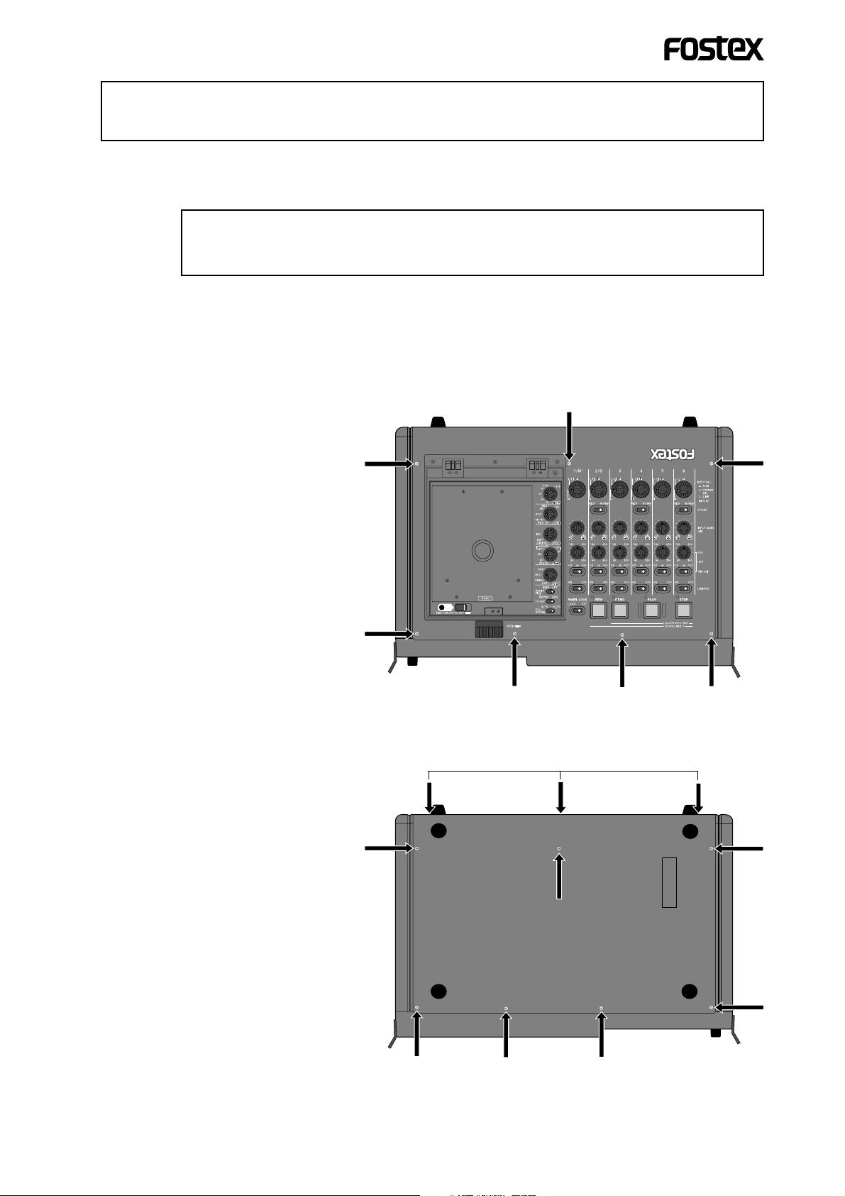
Unfasten the screws for fixing top panel, front panel, bottom panel and
right side panel in order (see figures 1 through 4 below).
T op panel (7 screws)
Bottom panel
Bottom side (7 screws)
Back side (3 screws)
<Figure 1>
Back side (3 screws)
1
<Figure 2>
Page 2
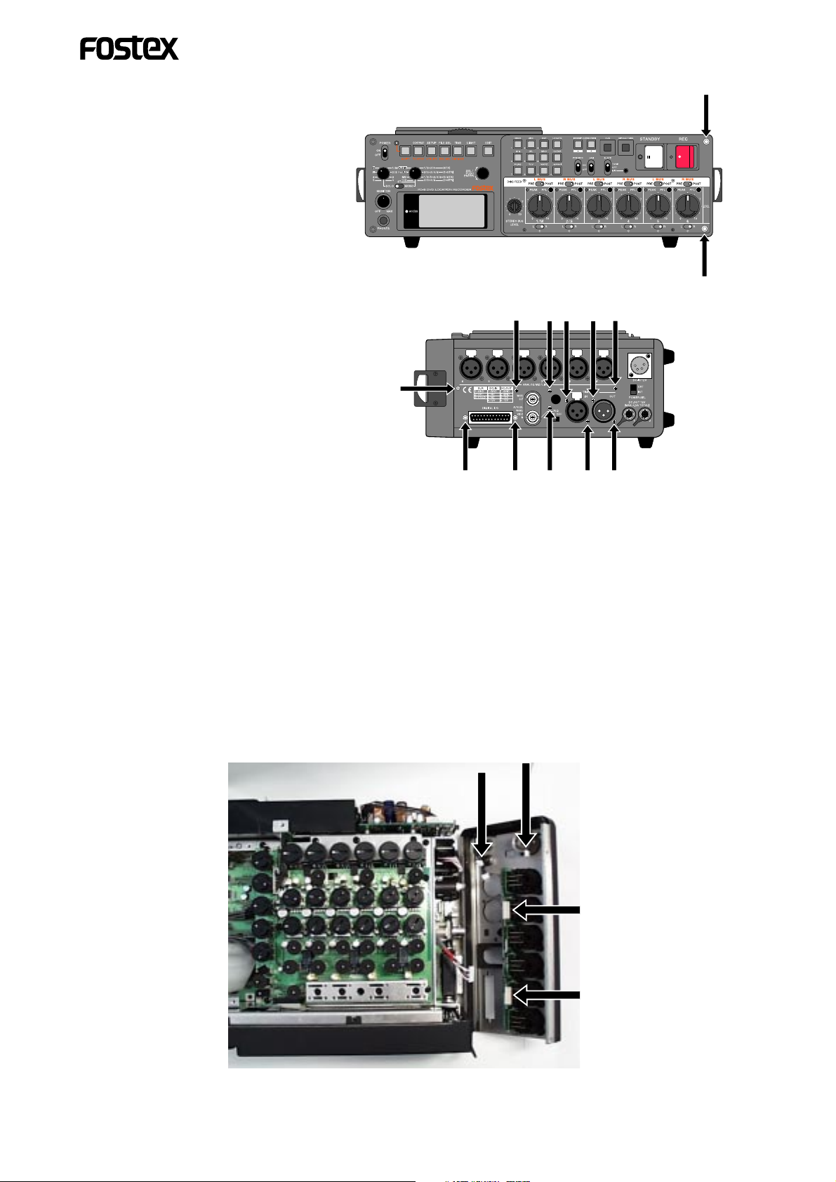
Front panel (2 screws)
Hex nut
<Figure 3>
Right side panel (11 screws)
Hex nut
<Figure 4>
Hex nut
<Step 2>
Remove the top and bottom panels. Then disconnect five cables which are
connected to the right side panel, and remove the right side panel as shown
in figure 5.
<Cables to be disconnected>
1) Cables connected to XLR IN (black and red) x 2
2) Cables connected to DC OUT x 2
3) Cable connected to DC IN x 1
Cables connected to DC OUT
<Figure 5>
2
Cable connected to DC IN
Black cable
Cables connected to XLR IN
Red cable
Page 3

<Step 3>
Fit the ATC-4 to the appropriate position on the side panel as shown in figure 6
below. Use the crow washer and hex nut to fix the ATC-4 firmly.
hex nut
connector
cable
Position f or fitting the ATC-4
side panel
<Figure 6>
crow washer
<Step 4>
Connect the connector of the ATC-4 to the "J1004" connector on the PCB main
board (see figure 7).
"J1004" connector
<Figure 7>
<Step 5>
After fitting the ATC-4 and making connection, reassemble the panels in the reverse order of disassembly.
3
 Loading...