

Fostex 8346 Owners Manual

APPENDIX
<Operation manual for the recorder with the Model 8346 TC/SYNC card installed>
This appendix is the operation manual for the recorder with the Model 8346
TC/SYNC card installed.
<Installation of the optional card>
The TC/SYNC card should be installed into the recorder at a FOSTEX service
station. Do not try to install the card by yourself. Ask your local FOSTEX
dealer for the installation after purchasing the Model 8346.
<Notes when requesting the installation>
There is the possibility of damaging the hard disk when transporting the recorder. Before transporting the recorder to our service department for the
installation of the TC/SYNC card, remove the hard disk from the recorder.
Be sure to keep the removed hard disk carefully.

APPENDIX (Operation manual for the recorder with the Model 8346 TC/SYNC card installed)
Contents of Appendix
Names and Functions.........................................................................3
Introduction..........................................................................................4
Additional features..............................................................................4
Operations for the additional SETUP menu......................................4
“Ref. TC ?” menu setting........................................................................4
“Clock Sel ?” menu setting....................................................................5
“Sync Preset ?” menu setting................................................................5
“Virtual L TC ?” menu setting.................................................................6
“Offset Disp ?” menu setting.................................................................6
Generator Setup..................................................................................7
How to enter the Generator Setup mode............................................7
Setting the time code recording mode................................................7
Editing the internal generator time code...........................................8
Force jamming to external time code..................................................8
Selecting the output time code............................................................8
Editing the chase offset.........................................................................9
Erasing the recorded time code...........................................................9
Chase sync to external time code....................................................10
Synchronization to w ord clock or video signal...............................11
Connection to a digital mixing console...........................................11
Contorl from a video editor (RS-422)...............................................13
2
APPENDIX (Operation manual for the recorder with the Model 8346 TC/SYNC card installed)
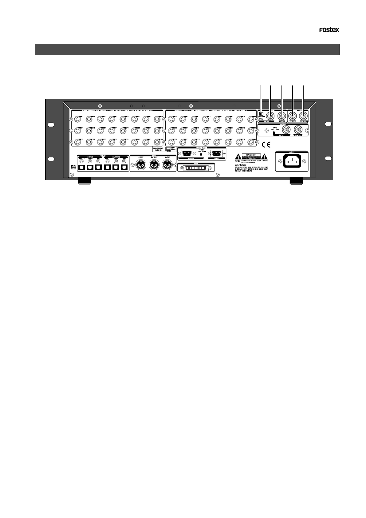
Names and Functions
4
1
2
3
5
1. [VIDEO IN] termination s witch
(75Ω termination ON/OFF)
Used to terminate the VIDEO INPUT signal and
usually set to ON.
2. [VIDEO IN] connector (BNC connector)
Receives an external video sync signal (interlace or composite) when synchronizing the
recorder to a video sync signal.
3. [VIDEO THRU] connector (BNC connector)
Outputs the video sync signal received from
the VIDEO INPUT connector.
4. [TIME CODE INPUT] connector
(BNC connector)
Receives external time code (LTC).
5. [TIME CODE OUTPUT] connector
(BNC connector)
Outputs an LTC from the recorder (equivalent to the MTC displayed on the panel) or
time code from the internal TC generator.
3
APPENDIX (Operation manual for the recorder with the Model 8346 TC/SYNC card installed)
Introduction
The Model 8346 is a TC/SYNC card designed as an
option for digital multitrack recorders.
By installing the TC/SYNC card into the recorder,
the recorder can synchronize to external LTC or
video signal, as well as an external word clock.
So you can use the recorder synchronized with video
machines in video post production studios where
the synchronization between audio and video is indispensable, or make digital sound recordings in a
system using a digital mixing console.
Additional features
By installing the Model 8346 into the recorder, the
following SETUP menus and GEN setup function are
added. These SETUP menus are used when the recorder is synchronized to an external LTC or locked
to a video signal.
1. SETUP mode “Ref. TC?” menu
This menu selects the reference time code used as a master time code for the recorder.
The reference time code can be selected between MTC
(MIDI time code) and LTC according to the incoming time
code. The default setting after formatting a disk is “LTC”.
2. SETUP mode “Clock Sel?” menu
This menu selects the reference clock of the recorder with
the 8346.
If the 8346 is not installed, you can select the reference
clock from “Int,” “Auto” and “Word”.
If the 8346 is installed, “Video” also can be the reference
clock in addition to the three options above.
Operations for the additional SETUP menu
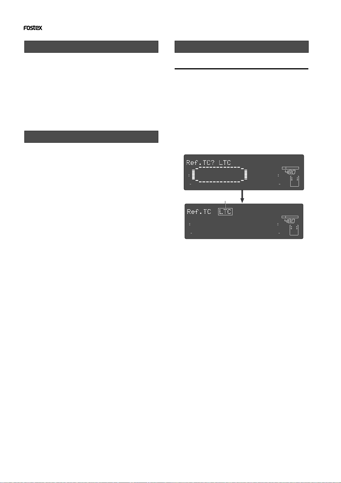
• "Ref. TC?" menu setting
1. T urn on the po wer of the recor der.
2. Press the [SETUP] key while the recor der is
stopped to show the SETUP menu.
3. Select the “Ref. TC?” menu by using the Jog dial
and press the [EXECUTE/YES] key.
The reference time code currently selected starts
flashing (the default reference time code setting when
the Model 8346 is installed is “LTC”).
The outlined box surrounds the flashing item on the
display.
SETUP
OL
0
3
6
9
12
18
24
30
42
∞
4
1
2
3
98765
17
16151413121110
Flashing
SETUP
OL
0
3
6
9
12
18
24
30
42
∞
4
1
2
3
98765
17
16151413121110
4. Select the reference time code b y using the Jog
dial.
You can select between “LTC” and “MTC” (MIDI time
code).
OL
24
BIT
0
3
6
9
12
18
24
30
42
∞
24
232221201918
OL
0
3
6
9
12
18
24
30
42
∞
24
232221201918
FS
kHz
CLOCK
INT
24
BIT
FS
kHz
CLOCK
INT
3. SETUP mode “Sync Preset?” menu
This menu is effective when the recorder with the 8346
installed is used in sync with a digital mixing console.
You can select from some preset options according to your
system to get the best synchronization performance.
4. SETUP mode “Virtual LTC?” men u
This menu selects whether recording/playback of the virtual LTC is enabled or disabled. The default setting is
“Ena.” (Enabled).
5. SETUP mode “Offset Disp?” menu
This menu selects whether or not displaying the real offset between the incoming reference time code (LTC or MTC)
and the displayed MTC (output LTC).
The real offset is displayed instead of REMAIN when displaying the MTC.
6. GENERATOR setup functions
The GENERATOR setup functions allows recording/erasing an external or internal (generator) time code, forcejamming to external time code, setting the LTC output,
and setting the chase offset value between incoming time
code and the MTC.
5. After selecting the reference time code, press the
[EXECUTE/YES] key.
The selected reference time code is confirmed (set) and
the display changes to the similar one to the upper
example in step 3 above where “?” flashes.
6. Press the [EXIT/NO] key (or the [STOP] button) to
exit the SETUP mode.
You can check the time information of the incoming
reference time code in the front panel display of the
recorder.
See "Chase sync to external time code" below for details.
4
 Loading...