

Page 1
1
i
(0280-H-04)
February 2018
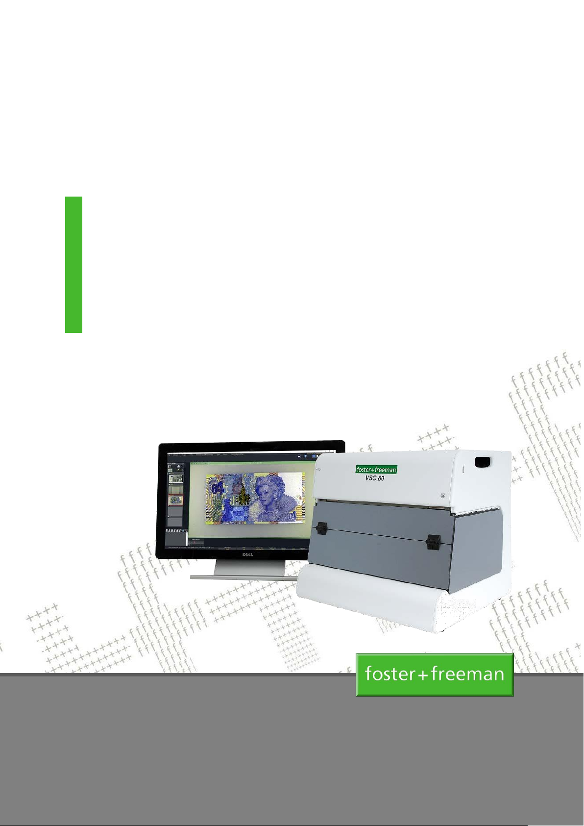
VSC®80
Video Spectral Comparator
User Manual
(Hardware)
Page 2

2
Head Office & UK Sales Office
Foster + Freeman Ltd
Vale Park
Evesham
Worcestershire
WR11 1TD
UK
+ 44 (0) 1386 768050
+ 44 (0) 1386 765351
www.fosterfreeman.com
US Sales Office
Foster + Freeman USA Inc
46030 Manekin Plaza
Sterling
Virginia 20166
USA
+1 888 445 5048
+1 888 445 5049
www.fosterfreeman.com
Sales Support and Feedback
Foster + Freeman welcome feedback from Customers regarding this product. Please contact one of our
offices if you would like to pass on your comments.
Foster + Freeman are pleased to offer advice, installation, training and on-site maintenance worldwide for
all of their products.
Specification
Foster + Freeman reserve the right to alter the specification of this product, accessories and consumables
without prior notice.
Copyright
This document contains proprietary information that is protected by copyright.
All rights are reserved. No part of this publication may be reproduced in any form whatsoever without the
prior, written permission of Foster + Freeman Ltd.
Copyright © Foster + Freeman Ltd
(0000-001-17) Copyright © Foster + Freeman Ltd
Page 3

PLEASE REFER TO THE WELCOME SECTION BEFORE USING THE EQUIPMENT FOR THE FIRST TIME
CONTENTS (HARDWARE)
Page
Welcome.................................................................................................................................... 4
Main unit .......................................................................................................................................... 6
Imaging system ............................................................................................................................... 8
Light sources ................................................................................................................................. 11
Optical filters .................................................................................................................................. 15
Document locator (V6/TRANS/DC) ............................................................................................... 17
Optically variable ink viewer ..........................................................................................................18
Additional Functions ......................................................................................................................19
Page 4
4
Important operating information
PLEASE READ THIS INFORMATION BEFORE USING THE EQUIPMENT FOR THE FIRST TIME
WELCOME
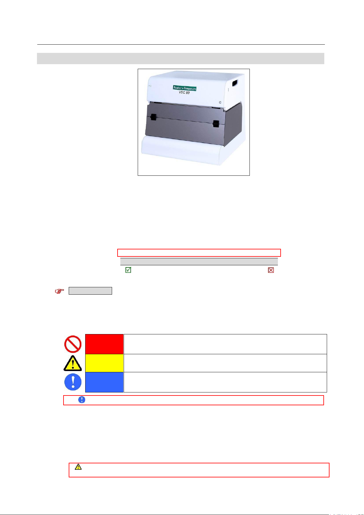
VSC®80/VSC®80i: Video Spectral Comparator
Welcome to the Foster + Freeman VSC®80/VSC®80i Video Spectral Comparator.
This equipment allows conducting technical studies of documents in laboratory conditions, checking the
requested documents, using a variety of lighting and viewing conditions.
This equipment allows you to examine questioned documents using a variety of illumination and viewing
conditions.
About this manual
Text
Text formats are used as follows:
Additional notes and advice
Good practice. Information on recommended procedures.
Bad practice. Information on procedures to avoid.
Control features
Illustrations
Illustrations are for explanatory purposes only. The appearance of the product, its components,
accessories and consumables may differ from that shown.
Safety and Warning Markers
PROHIBITED
Red markers prohibit certain actions or procedures. Disregard of these warnings may pose
a health or safety risk to the user or cause damage to the equipment.
CAUTION
Yellow markers warn of a hazard. The user should be aware of the associated risk and
take appropriate precautions.
MANDATORY
Blue markers advise of mandatory health and safety procedures. Disregard of the advice
may increase an associated risk.
About this product
Compliance
When correctly employed by appropriately trained personnel, this equipment is fully compliant with the
relevant standards laid down by the UK Health & Safety Executive (HSE).
Hazard protection
When correctly employed, this equipment provides the user with the necessary level of protection from
Before using the equipment for the first time, please read the safety information on the following pages.
Protection provided by the equipment may be impaired if the equipment is used in a manner not specified in the
operating instructions.
Page 5

5
operating hazards.
PLEA
SE READ THIS INFORMATION BEFORE USING THE EQUIPMENT FOR THE FIRST TIME
Certificate of conformity
This equipment is manufactured in conformity with the requirements of the relevant directives of the
European Community through compliance with a number of harmonised standards.
Calibration and adjustment
This equipment is correctly calibrated and adjusted at the time of manufacture.
Provided that the equipment is used in accordance with its operating instructions and is not maltreated, no
further calibration or adjustment is required.
A certificate of conformity for this product is available from Foster + Freeman Ltd
In the event of query, please contact Customer Support: [email protected]
Page 6
6
VSC®80: Main unit (Illumination modes)
VSC®80: Main unit
Video camera
Light sources
Optical filters
▪▪▪▪▪▪
Translucent panel
USER GUIDE
( (0280-004-02) Copyright © Foster + Freeman Ltd
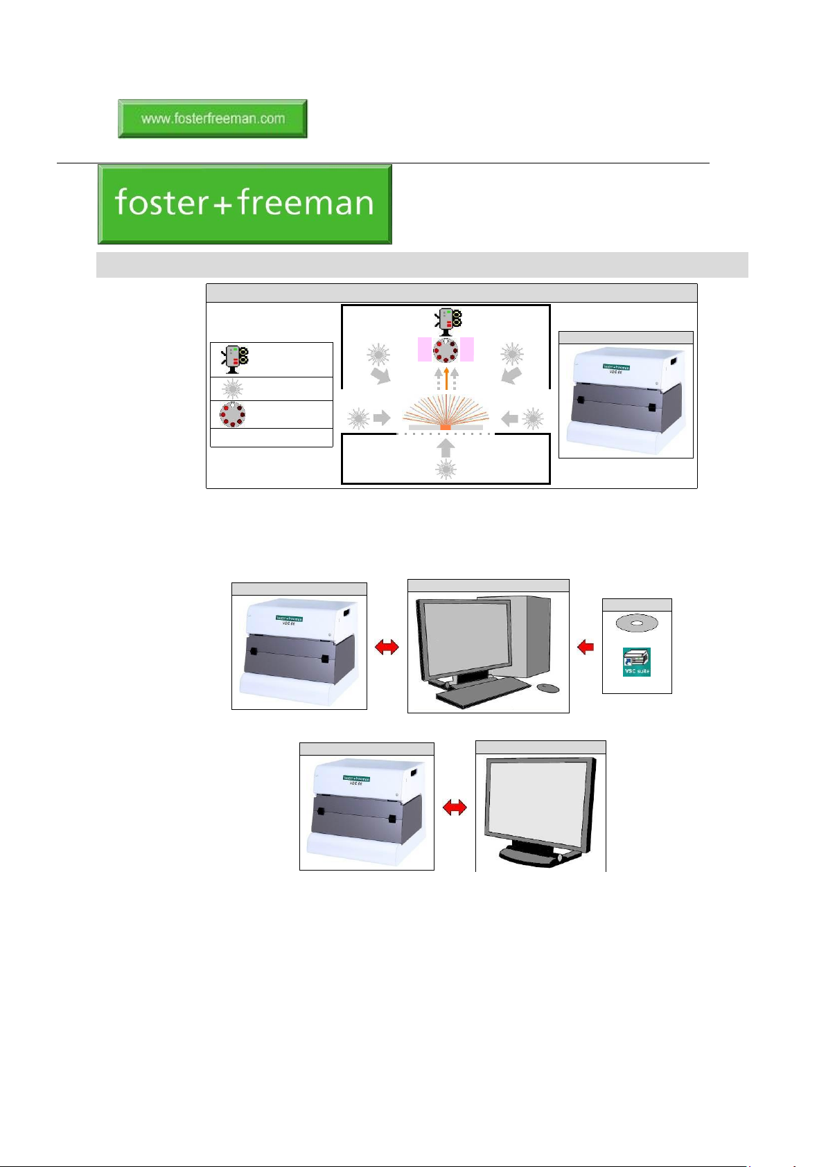
The VSC®80 is a powerful PC-based imaging system for examining documents of all types. The
document to be examined is placed on the platen under the canopy and a video image displayed on the
monitor. The VSC®80 main unit is controlled by the PC system and VSC® software. Alternative
configurations are available:
• PC system + VSC Software Suite:
• Embedded PC + Touchscreen monitor:
VSC®80: Main unit
VSC®80i: Touchscreen monitor
VSC®80: Main unit
PC system
VSC® software
CD-ROM
Desktop icon
VSC®80: MAIN UNIT
Page 7
7
Electrical specification
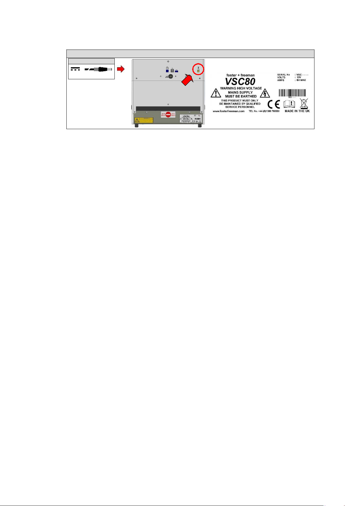
The VSC®80 can be operated from a compatible power source specified by Foster + Freeman. See:
Quick).
VSC®80: Main unit (DC power)
DC input
12 V DC; 5 A
Page 8
8
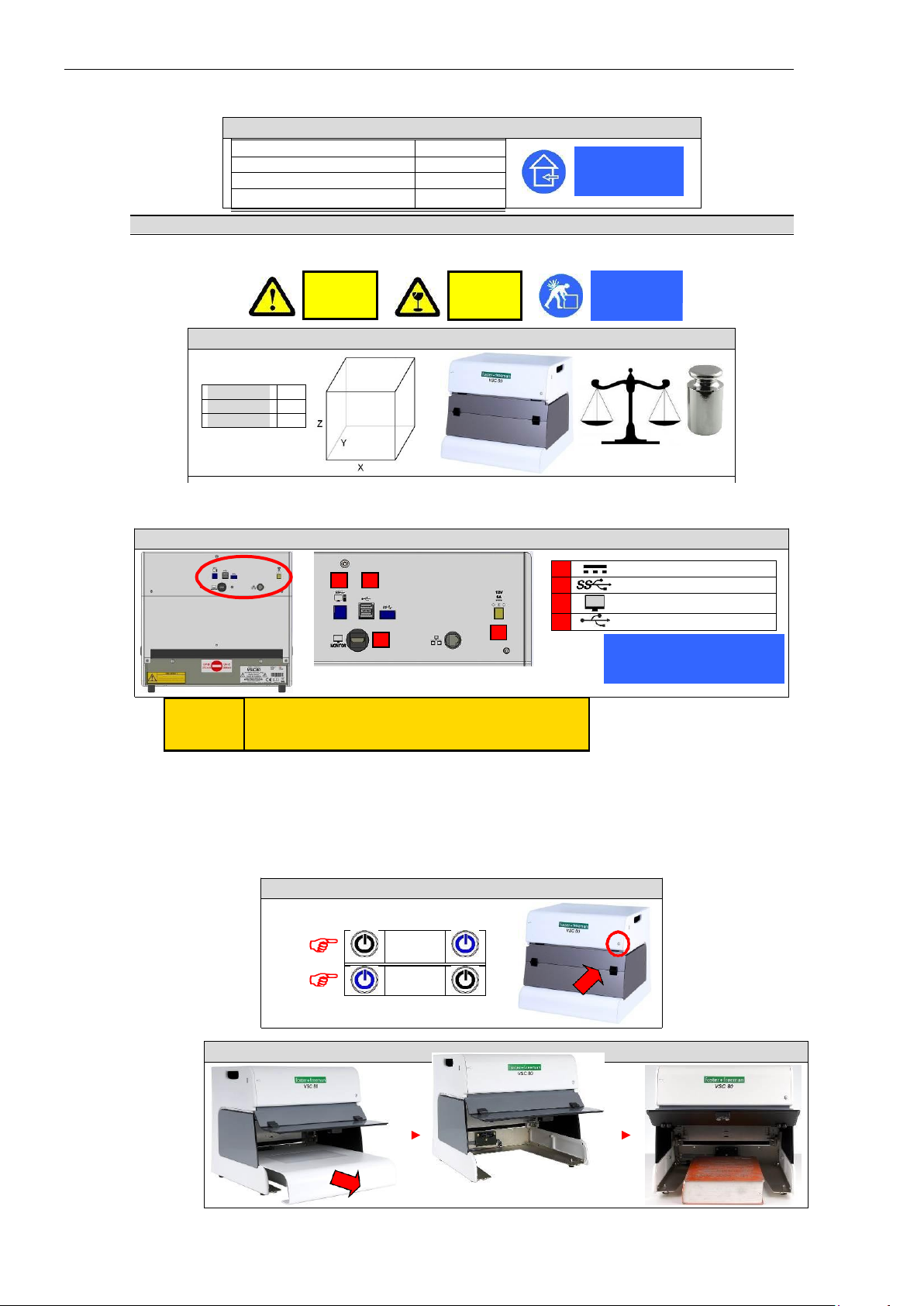
VSC®80: Main unit (On/Off control)
> 3 s
Environmental specification
Environmental specification
VSC®80: Main unit (Environmental specification: BS EN 61010-1:2010)
Location
Indoor use only
Indoor use only
Altitude
2000 m (Max)
Ambient temperature
5 – 40oC
Ambient humidity, RH% (5 – 31oC)
80%* (Max)
Mechanical specification
VSC®80: Main unit (Mechanical specificatio
Width: X (mm) 395
Depth: Y (mm) 375
Height: Z (mm) 365
12.5 kg
Electrical connections
See also: Quick Start Guide (Getting started) (p. 02-1).
◄
VSC®80: Main unit (Connection sockets)
1 DC input: 12 V DC; 5 A
2 4
2 PC system: SS-USB (3.0)
3 Touchscreen monitor: HDMI
4 Control connection: USB (2.0)
1
3
Equipment must be earthed
CAUTION: Possible optical radiation hazard. Do not stare at LEDs.
NOTICE: UV emitted from this product. Minimise exposure to eyes or skin.
Control switches
On/Off control (DC power)
Switch on
Switch off
* Decreases linearly to 50% within the temperature range 31 – 40oC
VSC®80: Removing the document platen
CAUTION
Heavy
CAUTION
Fragile
Lift correctly
Page 9
9
USER GUIDE
VSC®80: Main unit (Illumination modes)
VSC®80: Main unit
Video camera
Light sources
Optical filters
▪▪▪▪▪▪
Translucent panel
VSC®80: Document platen
Y
X
Translucent panel
Document platen
Field of view (User defined)
pixels
VSC®80: Video camera (Spectral response)
Wavelength (nm)
Video camera
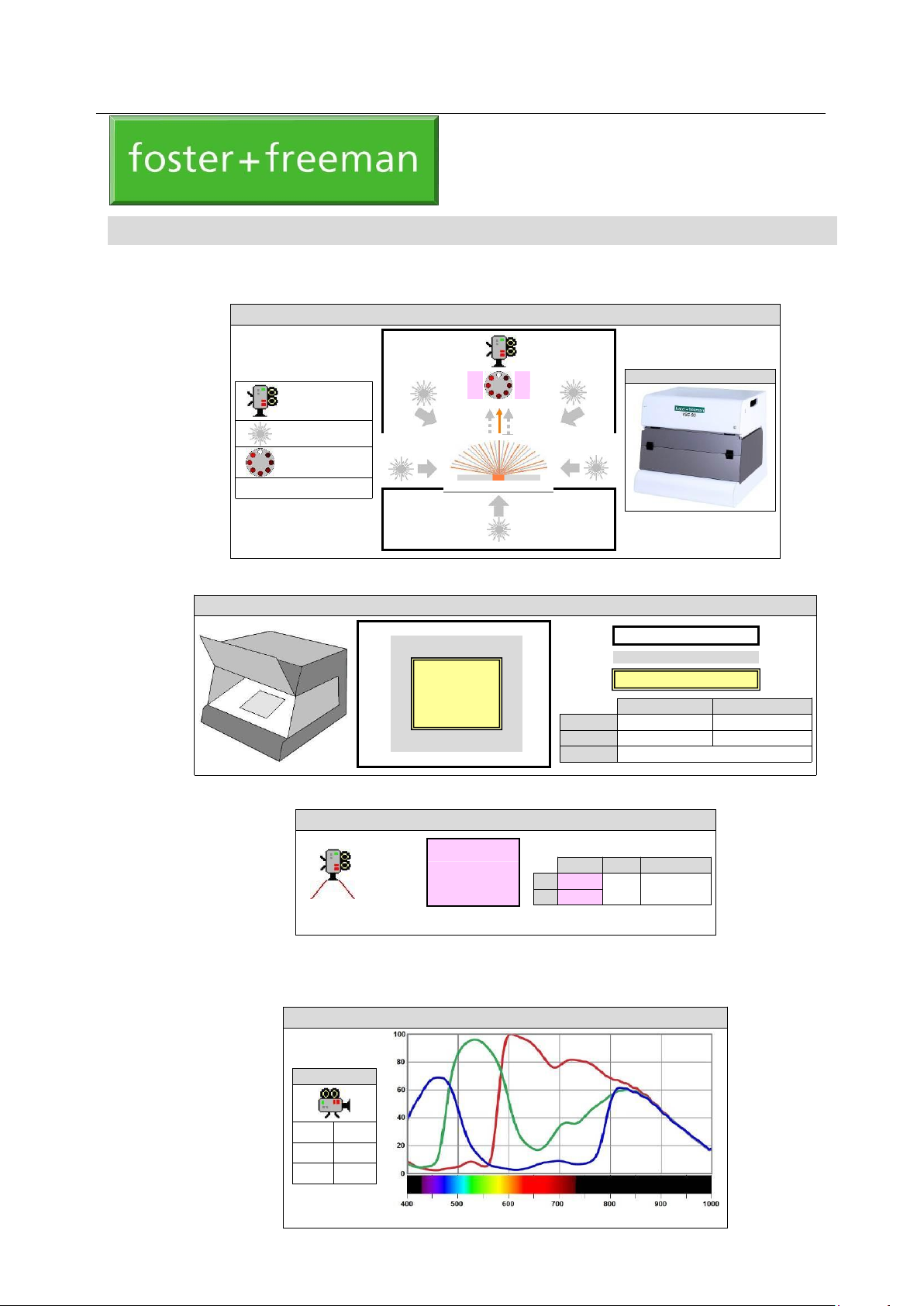
The VSC®80 is a powerful PC-based imaging system for examining documents of all types. The
document to be examined is placed on the platen under the canopy and a video image displayed on the
monitor:
Document platen
Video camera FULL HD
VSC is equipped with high-definition imaging cameras of type CMOS, which has an optical view of not x80 and Full HD video signal, autofocus. Adjustable dynamic focal range, with a resolution of 1920 x 1080 pixels
Spectral response
Video camera
▬▬
Red
▬▬
Green
▬▬
Blue
Document platen
Translucent panel
X (mm)
378
229
Y (mm)
320
135
Tilt angle
0
o
VSC®80: IMAGING SYSTEM
m
m
VSC®80: Camera image
▲
1080
pixels X/Y XY Mpixels
X 1920
▀▀▀▀▀▀▀
▼
Y 1080
16/9
2.13
◄
1920
►
Page 10
10
mm
VSC®80: Camera filters
Filter type
Longpass filter
Forensic application
Fluorescence examination;
Contrast enhancement.
Wavelength (nm)
Bandpass filter (VIS)
Normal viewing
(White light examination)
Wavelength (nm)
Monitor screen
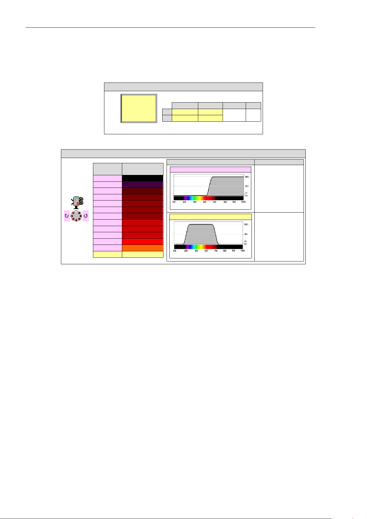
The photo-receptors, like those in the retina of the eye, respond to light in the red, green and blue parts of
the spectrum. The combined spectral response of the receptors also extends beyond the visible limits of
the unaided eye into the infrared and ultraviolet.
Field of view (Optical zoom)
The camera is provided with an optical system consisting of a motorised zoom lens and a supplementary
close-up lens.
Camera filters
Camera filters are provided as a range of mostly longpass filters with a variety of cut-off wavelengths.
For normal viewing, a shortpass or bandpass filter is used in the camera viewing path to mimic the
response of the unaided eye.
Filter setting
Cut-off wavelength
(nm) (50%)
13
1000
12
850
11
780
10
725 9 715
8
695 7 665
6
645 5 630
4
610
3
590
2
570
1
400 – 700
VSC®80: Field of view
▲
Y
X
Y
Max (mm)
200
112
Min (mm) Max/Min X/Y
7.8
4.4
25
16/9
▼
◄ X ►
Page 11
11
Monitor screen
Main image
Monitor screen
Main image (Magnification)
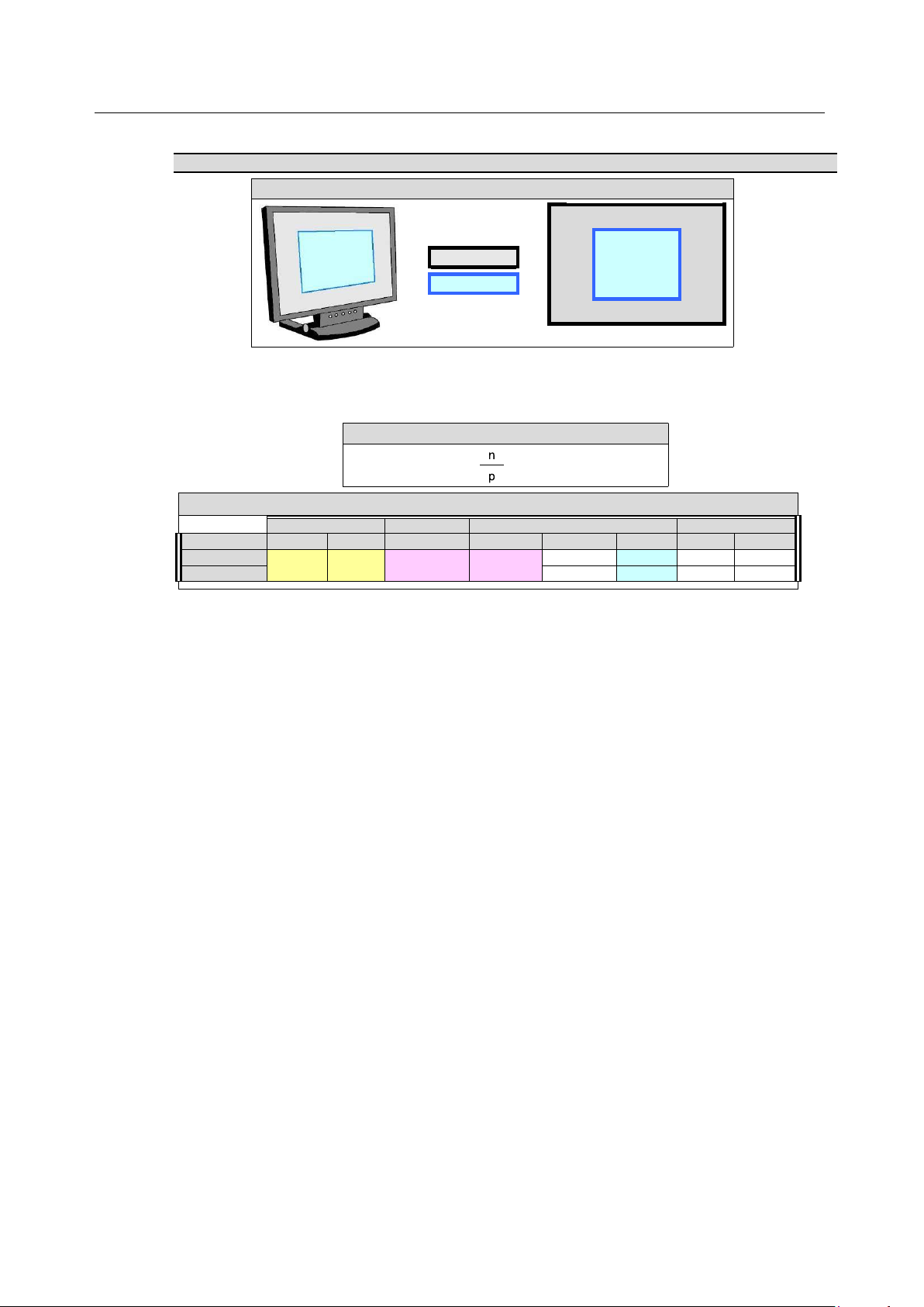
The dimensions of the main image are determined by:
• Image mode and the corresponding digital scaling factor, n, applied by the VSC® software;
• Density, p, of display pixels on the monitor screen.
VSC®80: Main image (Full resolution)
Field of view (mm)
Camera image
Main image (n = 1)
Optical magnification
Monitor screen
Maximum
Minimum
pixels
pixels
p: pixels/mm
mm
Minimum
Maximum
24”
200 x 112
7.8 x 4.4
1920 x 1080
1920 x 1080
3.7
517 x 323
2.6
80
27”
3.2
598 x 336
3.0
100
VSC®80: Monitor screen (Main image)
Y
X
m
m
The main image occupies only part of the display area of the monitor screen.
Main image (mm) =
VSC®: Main image
x Camera image (pixels)
Page 12
12
USER GUIDE
White
x1
IR850
x1
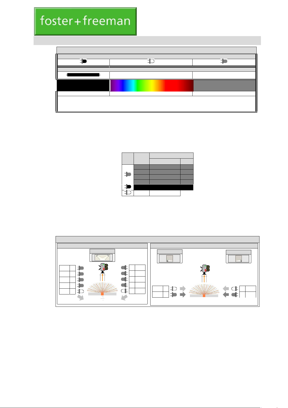
VSC®80: Reflected light sources: White/IR
Flood lighting (Reflectance contrast)
Software control
Side lighting (Oblique lighting)
Software control
Software control
x2 IR980
x2 IR940
x2 IR850
x2 IR780
x2 White
VSC®80: Light sources
Light emitting diodes
Vapour discharge tubes
Ultraviolet (UV)
Visible
Infrared (IR)
▲ ▲ ▲
▲
200
400
700
1000
Wavelength (nm)
A variety of light sources are available to provide illumination in the UV, Visible and IR parts of the
spectrum. Each of the main light sources is suitable for maximising the visual contrast of a specific type
of feature in a document: Technical Notes (Document examination) (p. 41-1). The VSC®80 main unit is
controlled by the PC system and VSC® software. Refer to the relevant User Manual for full details. See
also: Quick Start Guide (Replacing the lamps) (p. 03-1).
Light emitting diodes (LED)
LED Colour
Nominal wavelength (nm)
Bandwidth (10%)
Peak
IR980
880 – 1030
980
IR940
880 – 980
940
IR850
800 – 880
850
IR780
740 – 800
780
UV365
350 – 390
365
White
400 – 700
Light emitting diodes can be manufactured to produce narrow bandwidth light within an ever-expanding
part of the UV, visible and IR region of the electromagnetic spectrum. The bandwidth of the radiation is
generally much greater than that produced by vapour discharge tubes.
White light emitting diodes are normally manufactured by incorporating a phosphor into a blue LED. The
resulting white light therefore has a generally bluer appearance than that from incandescent lamps
Illumination modes: Reflected light sources
x1
White
x1
IR850
VSC®80: LIGHT SOURCES
IR980 x2
IR940 x2
IR850 x2
IR780 x2
White x2
Page 13
13
x2
UV365
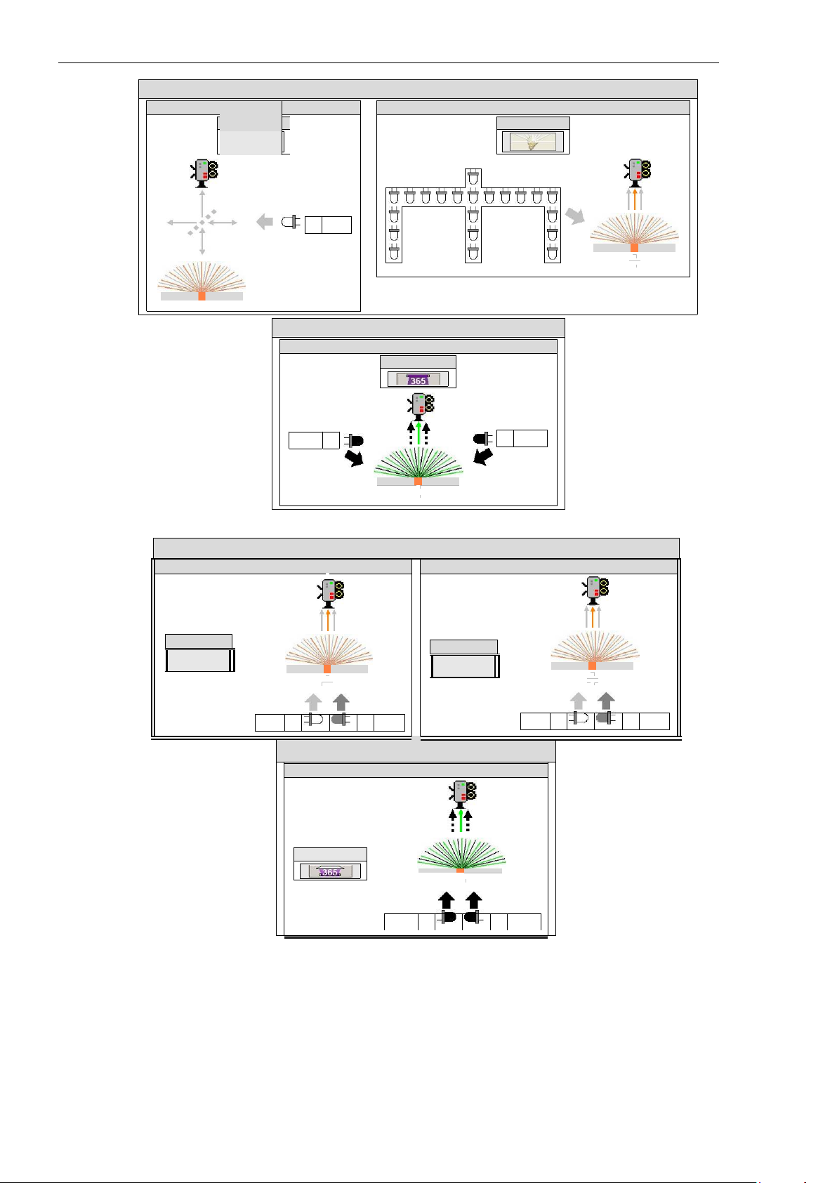
VSC®80: Reflected light sources: White
Coaxial l
flection)
Diffracted lighting (21 LED array)
Software control
VSC®80: Reflected light sources: UV365
Ultraviolet lighting (365 nm)
Software control
Light emitting diodes (LED)
ighting (Retro-re
Software control
Illumination modes: Transmitted light sources
VSC®80: Transmitted light sources: White/IR850
Transmitted lighting (Transmittance contrast)
Transmitted spot lighting (Transmittance contrast)
Software control
Software control
VSC®80: Transmitted light sources: UV365
Transmitted UV lighting
Software control
UV365
x2
White
x8
x6
IR850
White
x1
x1
IR850
UV365
x4
x4
UV365
x1
White
Page 14
14
VSC®80: Light sources (Vapour discharge tubes)
Mercury (Hg)
Wavelength (nm)
Vapour discharge tubes
Illumination modes: Reflected light sources (Spot lighting)
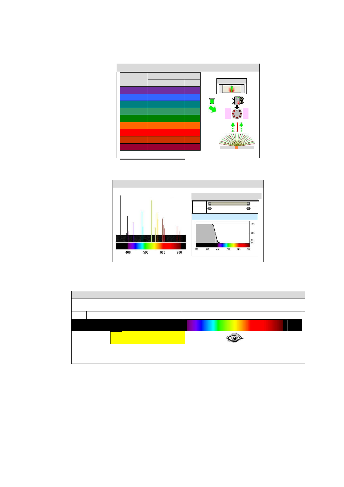
High intensity spot lighting sources are intended for the fluorescence examination of documents.
Differently coloured sources are available to suit the type of trace deposit sought. The sources may be
activated in any combination. An appropriate longpass filter must be used to view the fluorescence.
VSC®80: Reflected light sources: Spot lighting
Colour
Nominal wavelength (nm)
Bandwidth (10%)
Peak
Software control
Violet
395 – 440
410
Blue
420 – 485
445
Blue-Green
450 – 520
475
Cyan
475 – 535
500
Green
490 – 535
525
Orange
540 – 615
590
Red
600 – 655
640
Deep red
625 – 680
660
Far red
680 – 750
740
White
420 – 670
Vapour discharge tubes
Mercury vapour lamps
Vapour discharge lamps emit light with a narrow line spectrum that is characteristic of the vapour used.
Mercury vapour is suitable for producing emission at the wavelengths that are commonly used to excite
UV fluorescence: 313 nm (UV-B); 254 nm (UV-C). UV-B and UV-C sources are mounted behind
shortpass optical filters.
254
313
®
80: M
ercury vapour lamps
▼
UV
Visible
IR
UV-C
UV-B
UV-A
▲ ▲ ▲
▲
▲
100
180
280
315
400
7
Wavelength (nm)
313 nm
x2
254 nm
x2
Shortpass filter (λ < 400 nm)
Wavelength (nm)
Page 15
15
Vapour discharge tubes
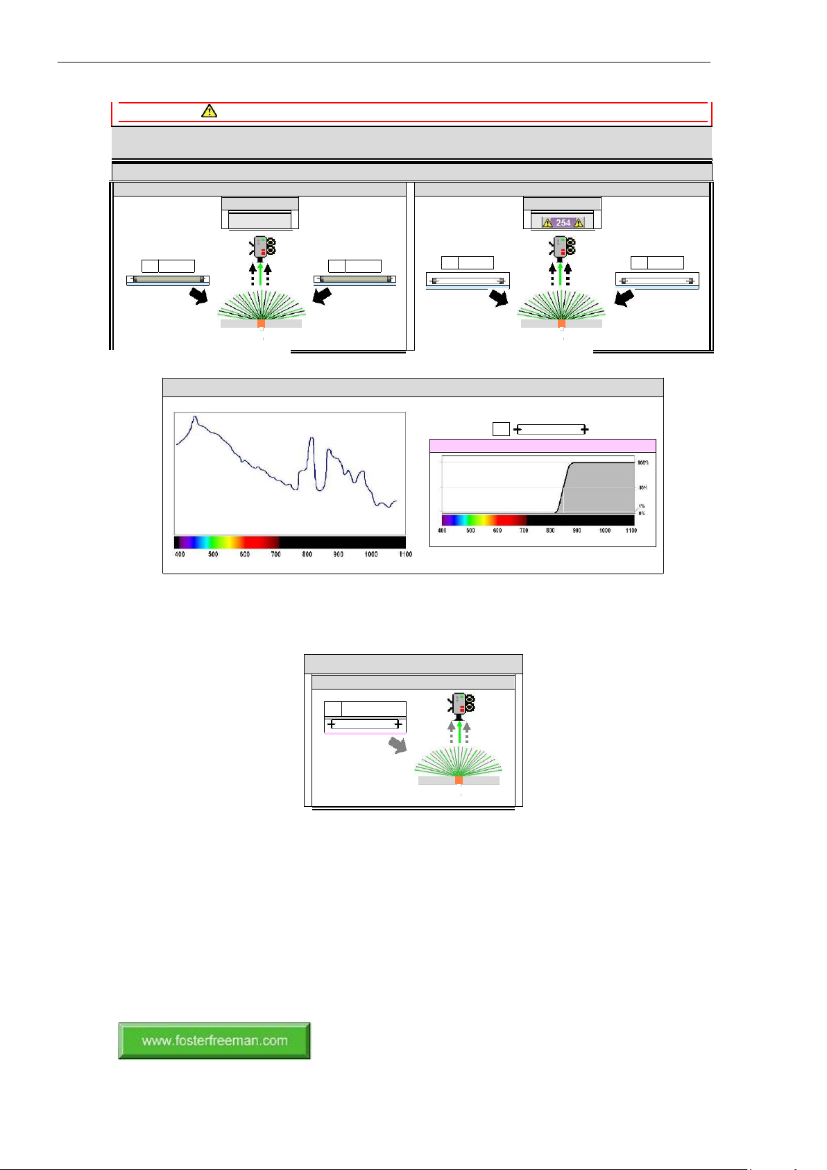
Illumination modes: Reflected light sources
Exposure to radiation from these sources can be hazardous to both eyes and skin.
The canopy flaps are electrically interlocked to prevent the operation of potentially hazardous light sources unless they
are properly lowered.
VSC®80: Reflected light sources: UV
Ultraviolet lighting
Ultraviolet lighting
Software control
Software control
313
x1 313 nm
x1 313 nm
Flash tube
VSC®80: Light sources (Flash tube)
Xenon (Xe)
x1
Longpass filter (λ > 850 nm)
Wavelength (nm)
Wavelength (nm)
Gas discharge lamps are designed to emit broadband radiation, the spectrum of which exhibits features
characteristic of the noble gas used: e.g. Xenon. Flash tubes are used, with appropriate filtering, to
provide intense IR light to excite Anti-Stokes fluorescence.
Illumination modes: Reflected light sources
VSC®80: Reflected light sources: IR
Flash lighting (840 – 1100 nm)
(0280-13-01) Copyright © Foster + Freeman Ltd
x1
840 – 1100 nm
Page 16
16
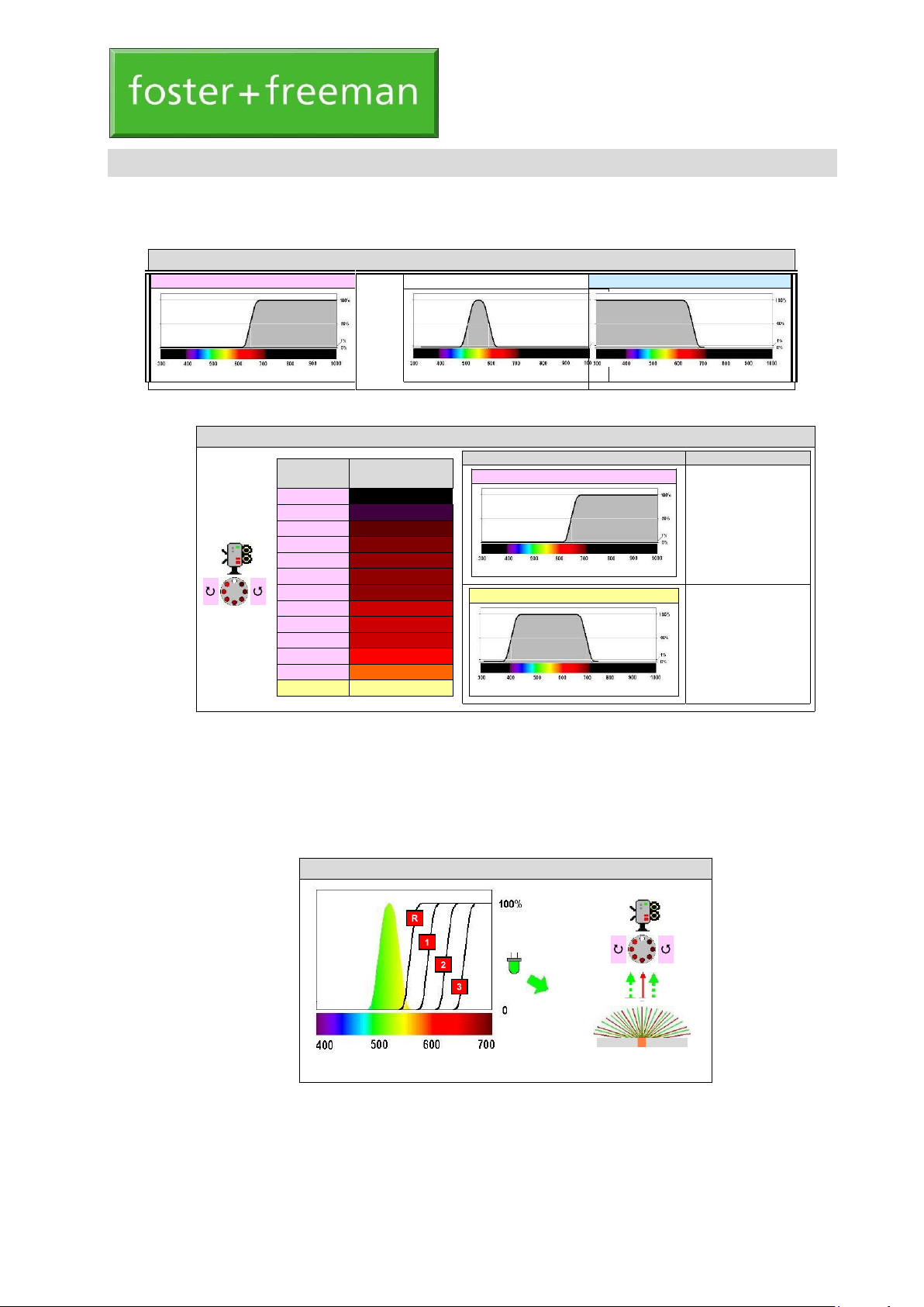
VSC®80: Camera filters
Filter type
Longpass filter
Forensic application
Fluorescence examination;
Contrast enhancement.
Wavelength (nm)
Bandpass filter (VIS)
Normal viewing
(White light examination)
Wavelength (nm)
VSC®80: Fluorescence examination (Safe fluorescence viewing filters)
Wavelength (nm)
(0280-14-02) January 2018
The VSC®80 main unit is controlled by the PC system and VSC® software. See: Software Manual
(Optical filters).
Filter types
VSC®80: Optical filters (Transmission spectrum)
Longpass filter
Bandpass filter
Wavelength (nm)
Shortpass filter
Wavelength (nm)
Wavelength (nm)
Camera filters
Camera filters are provided as a range of mostly longpass filters with a variety of cut-off
wavelengths. For normal viewing, a shortpass or bandpass filter is used in the camera viewing path
to mimic the response of the unaided eye. The optical filters are mounted on filter wheels
controlled by the VSC® software.
For normal viewing, a shortpass or bandpass filter is used in the camera viewing path to mimic
the response of the unaided eye.
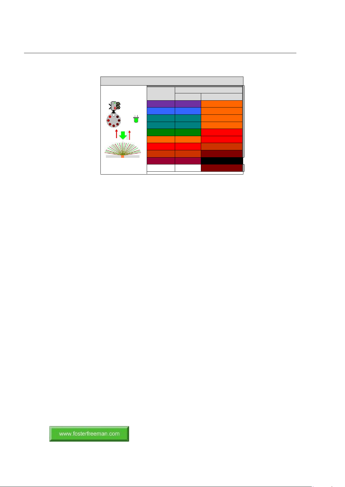
Fluorescence examination (Recommended setting)
The safe viewing of fluorescence requires a longpass filter whose cut-off wavelength exceeds the
long wavelength cut-off of the excitation light. For most wavebands of excitation light, there are
several safe viewing filters with progressively longer cut-off wavelengths. The recommended safe
viewing filter is generally the safe viewing filter with the shortest cut-off wavelength. Other safe
viewing filters with cut-
Filter setting
Cut-off wavelength
(nm) (50%)
13
1000
12
850
11
780
10
725
9
715
8
695 7 665
6
645
5
630 4 610
3
590 2 570
1
400 – 700
VSC®80: OPTICAL FILTERS
USER GUIDE
Page 17
17
Camera filters
off wavelengths that are longer than that of the recommended safe viewing filter may, in some
circumstances, improve visual contrast.
VSC®80: Fluorescence examination (Recommended setting)
Colour
Nominal wavelength (nm)
LED (10%)
Camera filter (50%)
Violet
395 – 440
570
Blue
420 – 485
570
Blue-Green
450 – 520
570
Cyan
475 – 535
570
Green
490 – 535
590
Orange
540 – 615
630
Red
600 – 655
695
Deep red
625 – 680
715
Far red
680 – 750
850
White
420 – 670
715
(0280-14-02) Copyright © Foster + Freeman Ltd
Page 18
18
(0020-15-13) December 2016
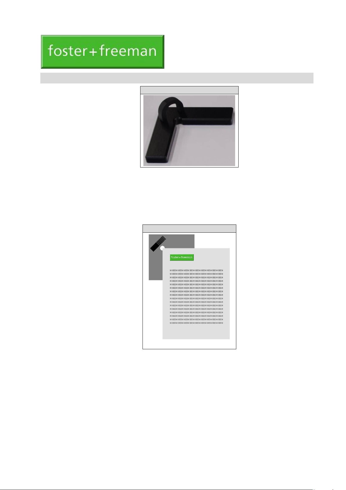
VSC®: Document Locator (V6/TRANS/DC)
The Document Locator is an accessory that can be used with any type of Video Spectral Comparator.
When placed in the required position on the document platen, the Locator allows documents of the same
type and shape to be precisely positioned within the field of view of the instrument.
The Locator comprises a right-angled edge stop into which the corner of the document is placed. The
Locator is provided with a high friction coating on its underside so that when positioned or re-positioned
on the document platen it is resistant to incidental movement.
Using the equipment
VSC®: Document Locator (V6/TRANS/DC)
Document + Document Locator
1.
Peel the protective covering from the underside of the Locator to expose the high friction coating.
2.
Using an example of the required type of document as a guide, position the Locator appropriately on
the document platen.
3.
Remove and replace documents, as required, ensuring that the corner of each document is securely
located during examination.
VSC®: DOCUMENT LOCATOR (V6/TRANS/DC)
USER GUIDE
Page 19
19
(0020-17-18) November 2016
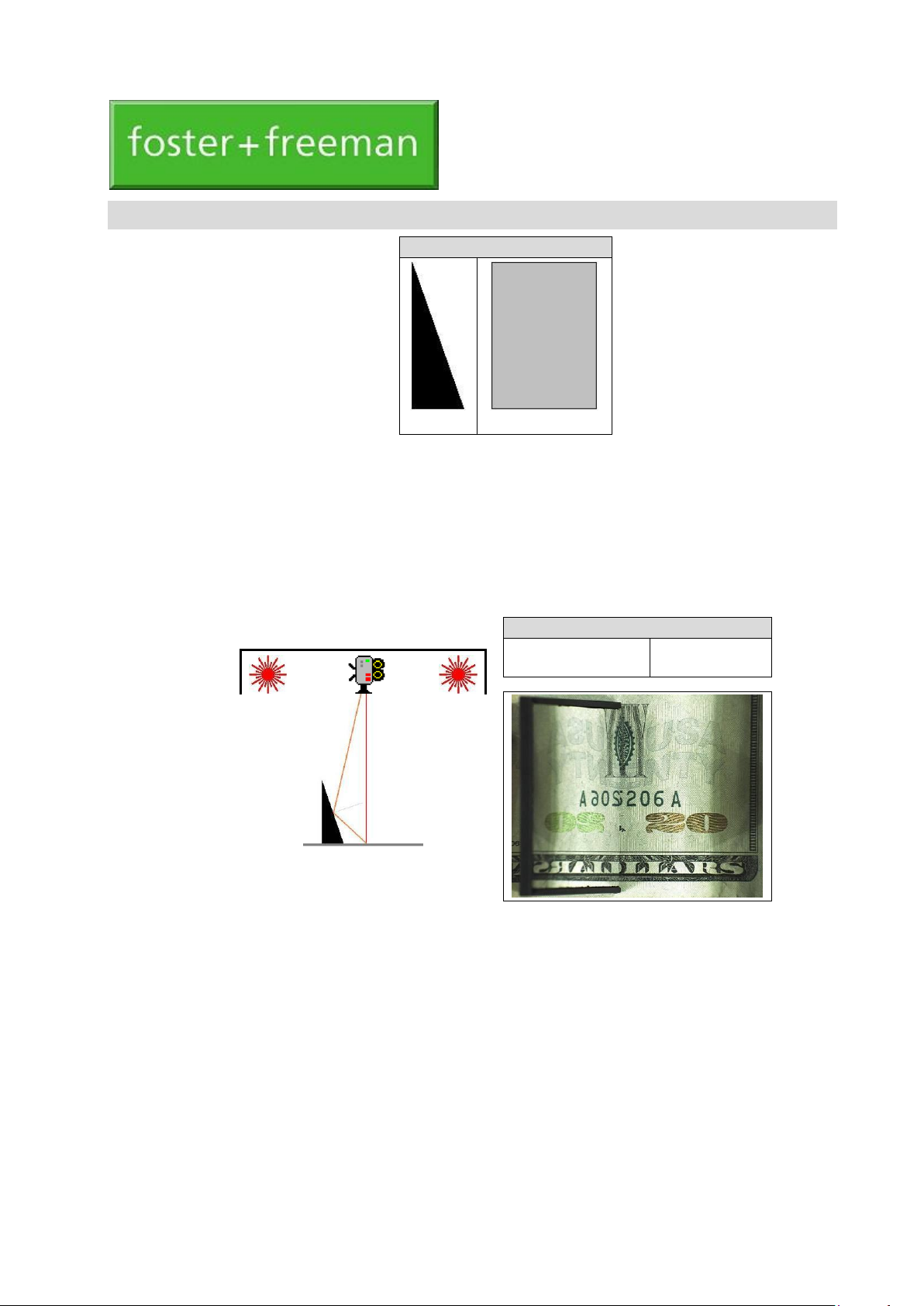
VSC®: Optically Variable Ink Viewer
Side view
Front view (Mirror)
The Optically Variable Ink Viewer is a mirrored accessory that can be used with any type of Video
Spectral Comparator. It allows the detection and assessment of document features that have been printed
using optically variable inks (OVI).
The OVI Viewer takes the form of an angled mirror which allows direct side-by-side comparison of the
appearance of an OVI feature as viewed by the VSC® camera:
1.
Normally, at an angle of 90o to the document;
2.
By reflection, at an angle of about 50o.
Using the equipment
1.
Place the document on the VSC® platen and display an image of the OVI feature at an appropriate
magnification.
2.
Place the Viewer on the document, with the mirrored face adjacent to the feature.
3.
Adjust the position and orientation of the Viewer so that the required direct and reflected images of
the feature are obtained.
Viewer + OVI
VSC®: Video image
2
Reflected viewing
1
Direct viewing
▼ ▼
VSC®: OPTICALLY VARIABLE INK VIEWER
USER GUIDE
Page 20
20
VSC®: Diffraction
VSC®: UV fluorescence
Excitation lig
(UV)
Excitation light
(UV)
Additional Functions
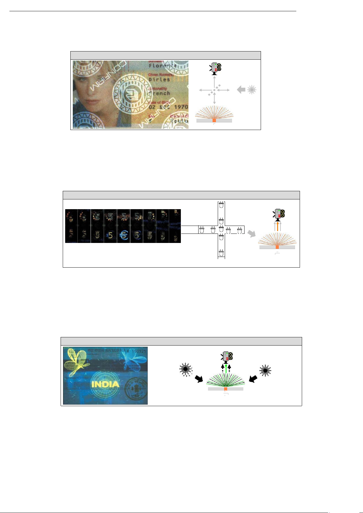
Angular contrast
Light may be reflected or diffracted by the topology or microstructure of a security feature only at particular angles.
Retro-reflection
Retro-reflective security features become visible when a semi-silvered mirror is used to illuminate the document coaxially
with the viewing direction.
Variations in surface relief (e.g. embossing or indentations) can be revealed by the shadowing produced by oblique
illumination.
Diffraction
Holograms and other diffractive optically variable devices (DOVD) may reveal different detail according to the particular angle
of illumination.
Fluorescence
Fluorescence examination is a widely applied forensic inspection technique for generating visual contrast from a variety of trace
materials when normal reflectance or transmittance variations are small. The effect was named by Sir George Stokes (1819 -
1903) after the mineral fluorspar (calcium fluoride, CaF2), in which the phenomenon was first observed. The process involves
absorption by a feature of particular wavelengths from the illuminating excitation source and re-emission of fluorescence light of
a different wavelength. Most commonly, the fluorescence light has undergone a Stokes shift to a longer wavelength (i.e. a colour
shift away from the excitation light, towards the red end of the spectrum). In general, the spectrum of the excitation light must
always be chosen to match suitable absorption bands in the feature.
UV fluorescence
UV Fluorescence can be stimulated from both trace materials and certain security features using a suitable UV source.
VSC®: Retro-reflection
▲
--M
---
---
▼
---
◄
N ►
→
→
→
→
→
Page 21
21
Narrowband excitation light
Absorption spectrum
Transmission spectrum of safe longpass viewing filter
Fluorescence emission
VSC®: Visible fluorescence
Excitation light
(Visible)
Fluorescence reveals an alteration
Visible fluorescence
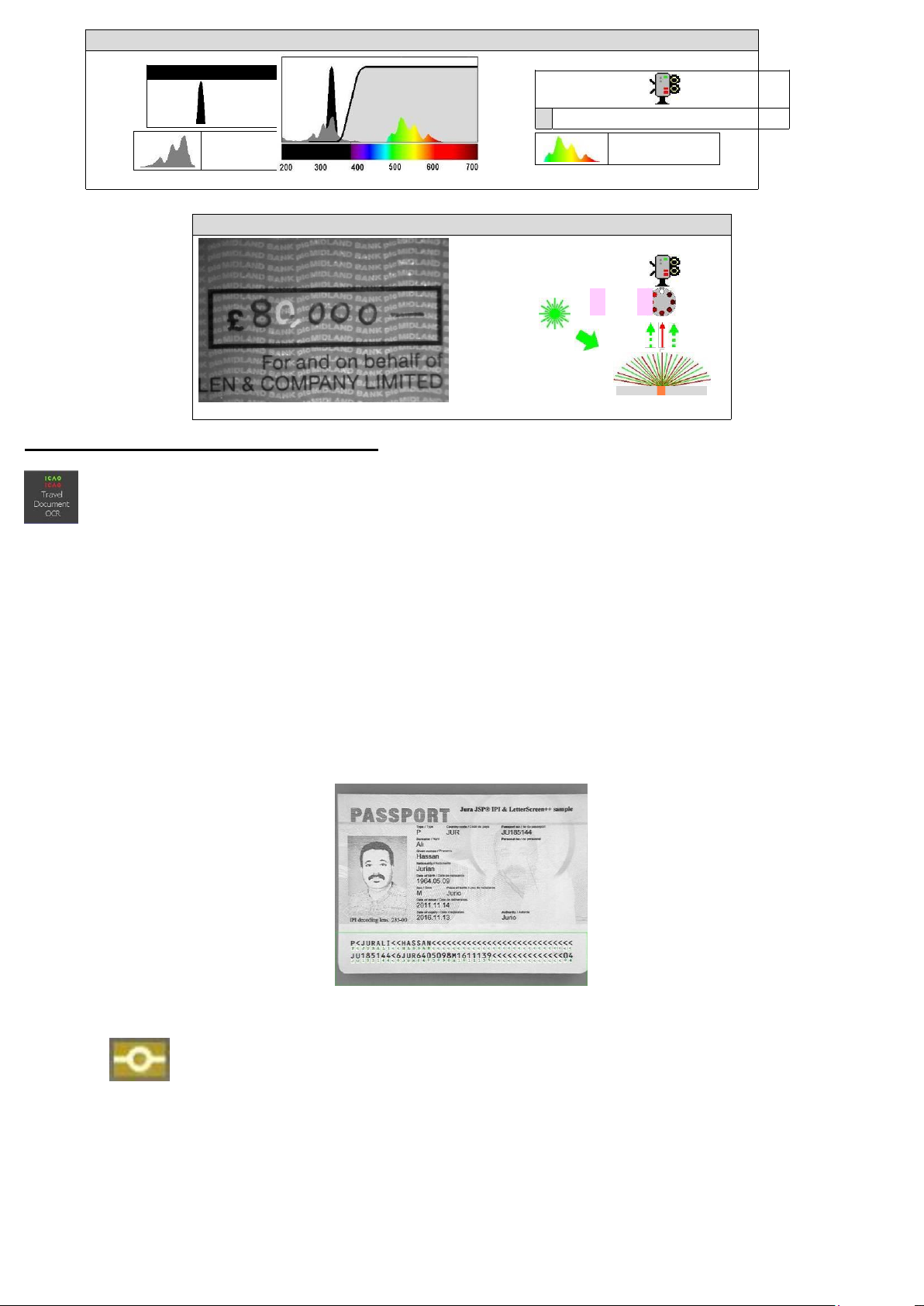
Optical Character Recognition (OCR)
The OCR feature reads the information within the Machine Readable Zone (MRZ). These are found within many documents
including passports, visas and identity cards. The function will work on Stored or Paused images of sufficient quality.
Activating the OCR feature will perform the following functions automatically:
• Opens the OCR control / information panel.
• Selects the 780 nm camera filter.
• Adjusts the magnification to a pre-set setting.
• Positions a green box at the bottom of the live image.
• Place the document so the MRZ is within the green box at the bottom of the live image:
e- Passport Reader
: (If applicable).
Some documents contain an RFID (Radio Frequency Identification) chip. Passports that have this chip have the e-passport logo on the
front cover. The chip reader is an optional extra, and must be attached to the PC before opening the VSC software.
To read the chip, click on the e-passport icon then follow the on-screen instructions. You must place the document on the chip reader
before clicking ‘OK’. If the MRZ on the document matches its counterpart on the chip, the image will appear in blank image area. The
user can then choose to save or print the image and bio data, copy
the data to clipboard, copy the image to clipboard or send the image and information directly to the Working Folder (p. 68).
Note: Before attempting to read the e-passport chip, the MRZ data must be successfully read first, as
VSC®: Stimulating and viewing fluorescence (Ultraviolet light)
Wavelength (nm)
Page 22
22
detailed above.
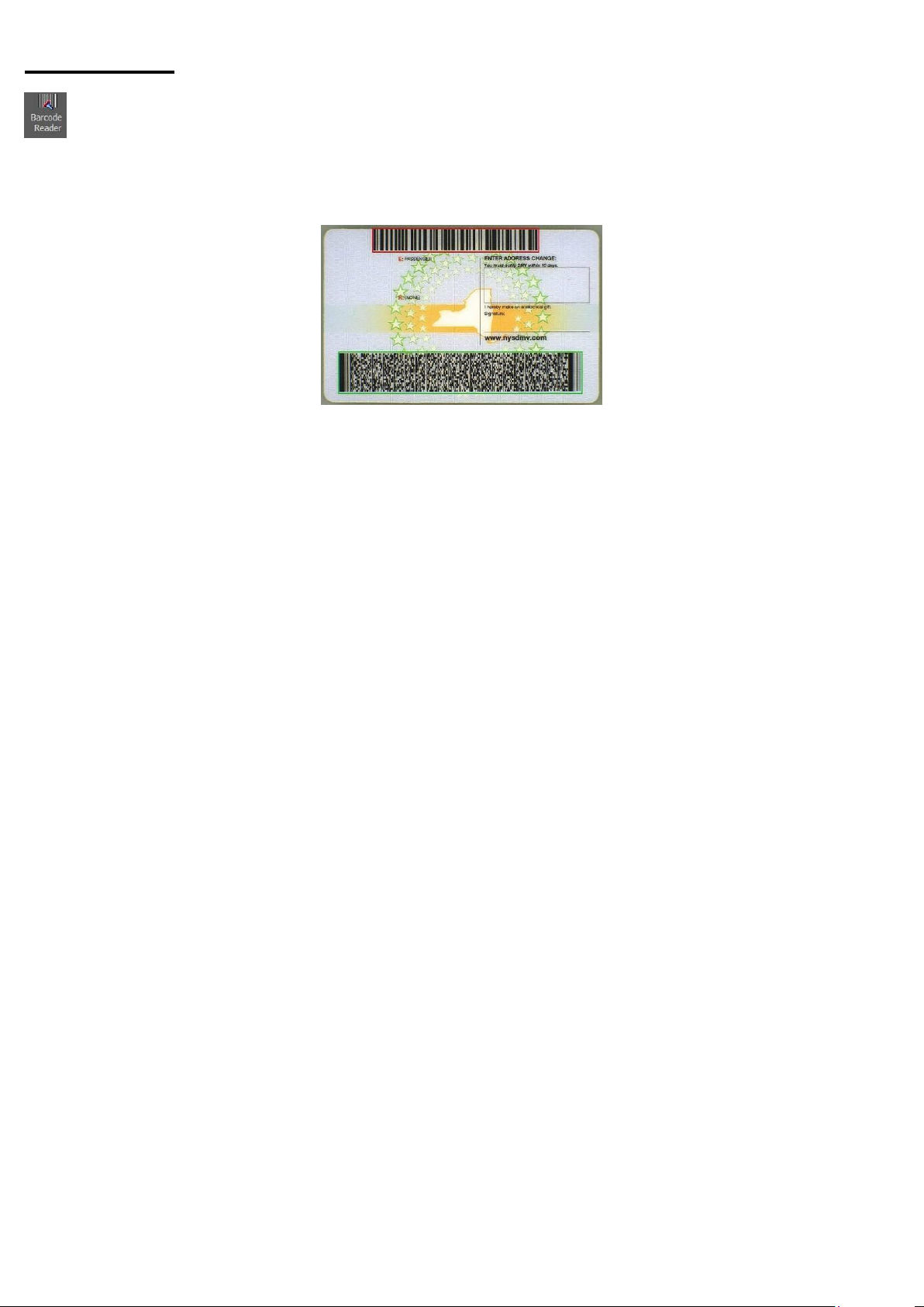
Barcode Reader
The barcode reader is a tool for reading both 1D and 2D barcodes found in many documents.
Before activating this feature, position the document in the VSC, magnifying the barcode and adjusting the focus if necessary. Click the
barcode reader icon to activate, and any barcode(s) should be highlighted. The barcode reader can read up to nine barcodes simultaneously.
Each barcode will be highlighted in a different colour.
The Barcode Reader toolbox will be displayed:
Page 23
23
VSC®: Anti-Stokes fluorescence
Excitation lig
(IR)
VSC®: Stimulating and viewing fluorescence (Infrared light)
Wavelength (nm)
Visual contrast
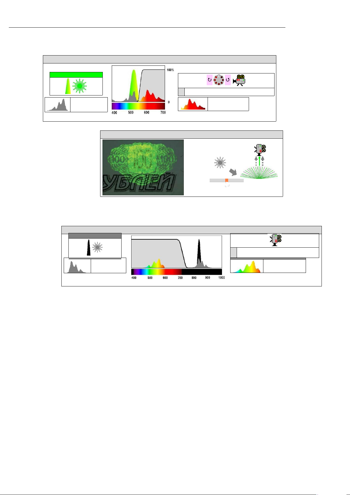
Visible fluorescence is stimulated in certain trace materials using narrow-band visible light. Differently coloured sources are
available to suit the type of trace deposit sought. The longer wavelength fluorescence must be viewed using a suitable
longpass filter.
Anti-Stokes fluorescence
Anti-Stokes fluorescence or IR Fluorescence 840-1100nm occurs in certain types of security inks and pigments. The process
differs from normal fluorescence in that the emission undergoes an anti-Stokes shift to a wavelength shorter than the excitation
radiation (i.e. a colour shift away from the excitation light, towards the blue end of the spectrum).
Narrowband excitation light
Absorption spectrum
VSC®: Stimulating and viewing fluorescence
Transmission spectrum of safe longpass viewing filter
Fluorescence emission
Wavelength (nm)
Narrowband excitation light
Absorption
spectrum
Transmission spectrum of safe shortpass
viewing filter
Fluorescence emission
Page 24
24
www.fosterfreeman.com
Head Office & UK Sales Office
Foster + Freeman Ltd
Vale Park, Evesham WR11 1TD
United Kingdom
Tel: + 44 (0) 1386 768050
Fax: + 44 (0) 1386 765351
 Loading...