

Page 1
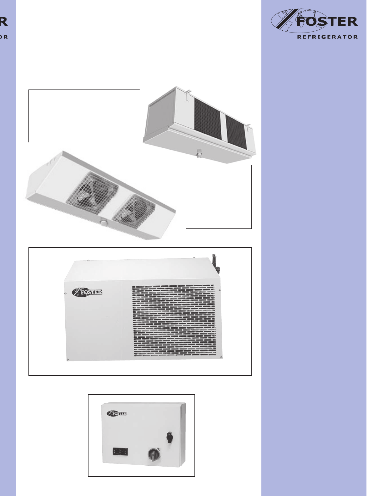
T e c h n i c a l M a n u a l
Duet Condensing
Unit/Cooler
Page 2

If not disposed of properly all refrigerators have components that can be harmful to the environment. All old refrigerators must be
disposed of by appropriately registered and licensed waste contractors, and in accordance with UK laws and regulations.
DISPOSAL REQUIREMENTS
2
CONTENTS
Page
Table of Contents 2
Duet Package Refrigeration System 2
Duet Specifications 3
Cooler Specifications 4
Condensing Unit Technical Data 5
FKS Cooler Dimensions 6
FTG Cooler Dimensions 7
Liquid and Suction Line Pipe Size 7
Control Panel 8
Microprocessor Controls - Duet HV, GP Series 8
Thermostat Function 8
Display 8
Microprocessor Controls - Duet C, F, M, and L Series 9
Thermostat Function 9
Display 10
Controller Parameter Settings 10-11
Electrical System Description 11
Duet Package Wiring Schematic 12
Duet Installation Guidelines 13
ENVIRONMENTAL MANAGEMENT POLICY.
PRODUCT SUPPORT AND INSTALLATION CONTRACTORS
Foster Refrigerator recognises that its activities, products and services can have an adverse impact upon the environment. The organisation is committed to implementing systems and controls to manage, reduce and eliminate its adverse environmental impacts wherever possible, and has formulated
an Environmental Policy outlining our core aims. A copy of the Environmental Policy is available to all contractors and suppliers upon request.
The organisation is committed to working with suppliers and contractors where their activities have the potential to impact upon the environment. To
achieve the aims stated in the Environmental Policy we require that all suppliers and contractors operate in compliance with the law and are committed
to best practice in environmental management.
Product Support and Installation contractors are required to:
1. Ensure that wherever possible waste is removed from the client’s site, where arrangements are in place all waste should be retumed to Foster
Refrigerator’s premises. In certain circumstances waste may be disposed of on the clients site; if permission is given, if the client has arrangements in
place for the type of waste.
2. If arranging for the disposal of your waste, handle, store and dispose of it in such a way as to prevent its escape into the environment, harm to human health, and to ensure the compliance with the environmental law. Guidance is available from the Environment Agency on how to comply with the
waste management ‘duty of care’.
3. The following waste must be stored of separately from other wastes, as they are hazardous to the environment: refrigerants, polyurethane foam,
oils.
4. When arranging for disposal of waste, ensure a waste transfer note or consignment note is completed as appropriate. Ensure that all waste is correctly described on the waste note and include the appropriate six-digit code from the European Waste Catalogue. Your waste contractor or Foster
can provide further information if necessary.
5. Ensure that all waste is removed by a registered waste carrier, a carrier in possession of a waste management licence, or a carrier holding an appropriate exemption. Ensure the person receiving the waste at its ultimate destination is in receipt of a waste management licence or valid exemption.
6. Handle and store refrigerants in such a way as to prevent their emission to atmosphere, and ensure they are disposed of safely and in accordance
with environmental law.
7. Make arrangements to ensure all staff who handle refrigerants do so at a level of competence consistent with the City Guilds 2078 Handling Refrigerants qualification or equivalent qualification.
Page 3
Duet Specifications
3
Duet Package Refrigeration System
The Duet Package Refrigeration System Comprises of:
Air Cooled Condensing Unit (standard items)
• Compressor
• Air cooled condenser
• Liquid receiver
• High/Low pressure switches
• Liquid line sight glass
• Filter Drier
• Liquid/Suction line shut off valves
• Crankcase heater (except DCU1-1H, DCU2-1H, DCU1-1L as option)
• Low ambient kit (only DCU5-3L, DCU6-3L others as option)
• Mounting Channels (DCU6-3H, DCU 7-3H, DCU 5-3L only)
• R404a refrigerant
• White unit cover
Cooler
• FTG Range with and without electric defrost heaters
• FKS Range with and without defrost heaters
Control Panel
• Microprocessor Controller c/w function indicators
• Ten metre sensing probes
• Component contactors
• Component circuit breakers
Not included
• Interconnecting pipework
• Pipe installation
• Mechanical fasteners (screws, pipe clamps etc.)
• Refrigerant
• Mains supply wiring
• Lockable isolator switch
• White enclosure
• Remote alarm contacts
Ancillaries (supplied loose)
• Expansion valve
• Liquid line solenoid valve
• Drain line heater (where applicable)
• Cooler fixing nylon bolts c/w nuts and washers
Options
• Wall brackets
• Oil separator (except DCU1-1H, DCU2-1H, DCU1-1L)
• Low ambient kit (except DCU5-3L, DCU6-3L this fitted as standard)
• 220-1-60hz in lieu of 230-1-50hz
• 220-3-60hz in lieu of 400-3-50hz
Page 4
Duet Installation Guide Notes
1. GENERAL
Installation should be carried out by competent persons adopting
codes of good refrigeration practices as detailed in BS.EN 378-1:2000
Refrigerating Systems and Heat Pumps - Safety and environmental
requirements. Particular care should be taken installing horizontal and
vertical pipe runs incorporating correct bends, traps etc.
2. CONDENSING UNIT
Although the Condensing Unit is rated to operate in an ambient
temperature up to 43°C it is still important to consider the location
of the Unit during installation. Solar Gain from direct sunlight can
raise the temperature inside the unit housing beyond the operating
specification of the unit resulting in loss of performance and possible
damage to equipment.
Equally protection from very low ambient conditions should be addressed
Basically consider protection components such as oil separators, head
pressure control, additional solenoid valves, crankcase heaters etc for
adverse operating conditions.
The Condensing Unit can be positioned at low level ensuring that it is
raised off the ground and mounted on wall fixing brackets. There should
be at least 600mm clearance in front of the unit to allow for adequate
air to the condenser plus access for servicing through the top therefore
at least 600mm clearance should be allowed.
3. PIPE RUNS
The nominal design pipe run for the system is 50 metres however care
should be taken to consider any vertical rise where the condensing unit
is situated above the coldroom. The introduction of “P” traps in the
suction line to aid oil return to the compressor should be considered
also the requirement of an oil separator, especially low temperature
applications. Where the vertical rise is 5 metres and above the use of
an oil separator should be considered, especially on low temperature
applications, plus the position of the oil “P” trap and the size of the
suction line to maximise oil return to the compressor.
4
Cooler Specification
Page 5
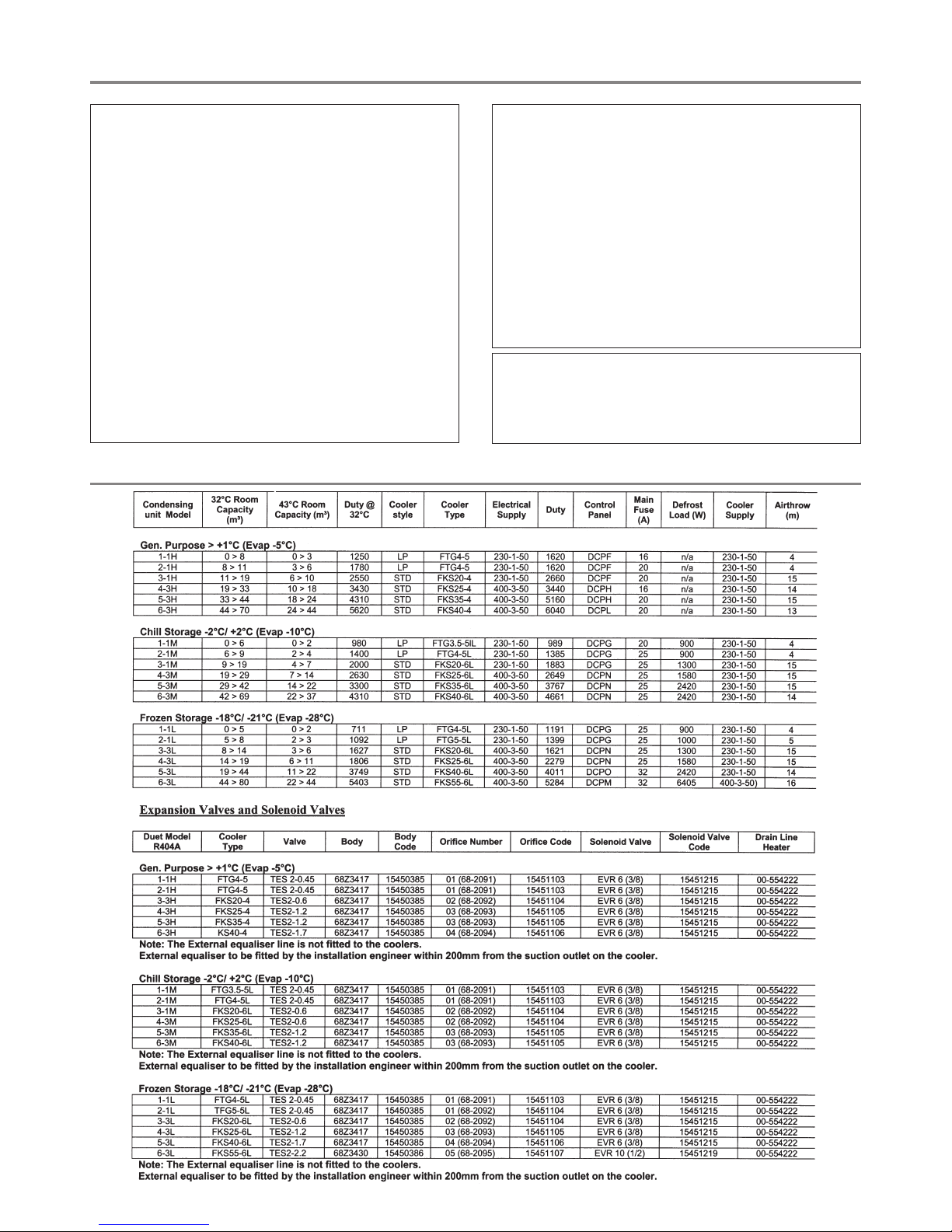
CONDENSING UNIT TECHNICAL DATA
Receiver** HP LP *Max Max Cond Air ***Unit Net Dimensions Liquid Suction
Model
Nom
Refrigerant
Gas
Capacity Setting Setting
Electrical supply
*Abs
*Nom Run
Start
Fuse Fan Motor
Volume
Absorbed Noise
kgs
Ht x w x d Line Line
hp
Charge
Its Bar Bar Volts Phase Hz
Kw
Amps Amps
Amps
Rating x mm
m3/hr
Watts Level dBa
Weight
mm mm mm
NOTE:
* Based on 40°C condensing temperature.
** Based on 80% liquid capacity at 40°C condensing temperature.
*** Based on 3 metres from front of unit, 1.5 metres from floor level.
DCU1-1H 0.5 R 404a 1.00 1.6 28 0.2 230 1 50 0.5 3.2 6.3 19 13 1 x 250 750 1 x 90 59 39 368 x 660 x 330 10 12
DCU2-1H 0.75 R 404a 1.00 1.6 28 0.2 230 1 50 0.7 3.7 7.8 31 20 1 x 250 750 1 x 90 60 43 368 x 660 x 330 10 16
DCU3-1H 1 R 404a 1.60 2.5 28 0.2 230 1 50 1.1 5.1 11.3 32 20 1 x 300 1400 1 x 90 60 61 458 x 880 x 400 10 16
DCU4-3H 1.8 R 404a 2.00 2.5 28 0.2 400 3 50 1.7 3.6 6.6 18 16 1 x 330 1500 1 x 120 62 62 458 x 880 x 400 10 16
DCU5-3H 2.3 R 404a 2.00 2.5 28 0.2 400 3 50 2.1 4.4 8.1 25 20 1 x 330 1500 1 x 120 63 64 458 x 880 x 400 10 22
DCU6-3H 3 R 404a 6.00 6.5 28 0.2 400 3 50 3.2 6.2 9.7 27 20 1 x 400 3100 1 x 160 64 102 595 x 1075 x 532 10 22
DCU1-1L 0.75 R 404a 1.50 1.6 28 0.2 230 1 50 0.8 3.8 7 28 16 1 x 250 750 1 x 90 60 46 368 x 660 x 330 10 16
DCU2-1L 1.8 R 404a 1.60 2.5 28 0.2 230 1 50 1.4 8.6 16 40 20 1 x 300 1400 1 x 90 60 60 458 x 880 x 400 10 22
DCU3-3L 2.3 R 404a 1.60 2.5 28 0.2 400 3 50 1.8 4.5 6.2 25 16 1 x 300 1400 1 x 90 61 65 458 x 880 x 400 10 22
DCU4-3L 3 R 404a 2.00 2.5 28 0.2 400 3 50 1.8 4.8 5.8 30 20 1 x 350 1500 1 x 120 61 73 458 x 880 x 400 10 22
DCU5-3L 4 R 404a 6.00 6.5 28 0.2 400 3 50 3.8 7.9 12.7 71 25 1 x 400 3100 1 x 160 68 120 595 x 1075 x 532 10 28
DCU6-3L 7.5 R 404a 10.00 12 28 0.2 400 3 50 5.8 12 24.8 80 25 1 x 450 3100 1 x 160 72 187 654 x 1575 x 642 12 35
5
Condensing Unit Wall Brackets
The wall brackets are supplied in two sizes. The first bracket part number 00-876220-01, size 900 x 430 is used on models :- DCU1-1 H, DCU 2-1 H, DCU 3-1 H, DCU 4-3H, DCU 5-3H,
DCU 6-3H, DCU 1-1L, DCU 2-1L, DCU 3-3L, DCU 4-3L.
The second bracket part number 00-876221-01, size 1200 x 600 is used on models ;- DCU 5-3L, DCU6-3L.
The brackets should be fitted approximately 150mm from each end of the unit at a height determined by site conditions.
Important
Allow adequate space around the unit for air circulation and easy removal of panels for service requirements
Page 6

Electrical System Description
The Duets are to be wired in accordance with the latest revision of the respective wiring diagram:
SEE DETAIL FOR REMOTE ALARM CONNECTION
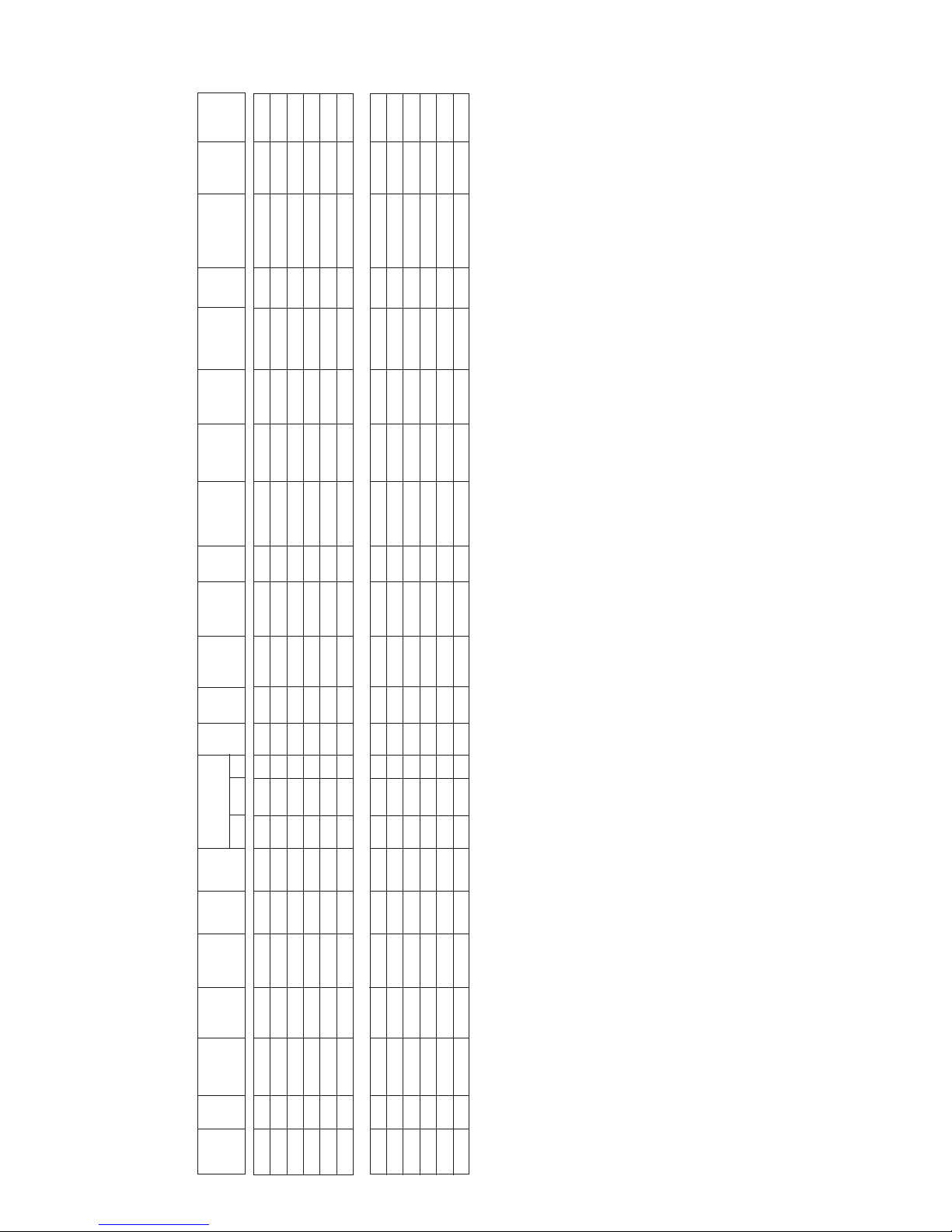
Par. No. 1 2 3 4 5 6 7 8 9 10 11 12 13 14 15 16 17 18 19 20 21 22 23 24 25 26
DUET ‘C’, ‘F’, ‘M’, ‘L’ AND ‘IC’ SERIES
Units Deg Deg Deg Min Min % Sec Hrs Deg Min Min Min Flag Flag Min Deg Flag Deg Deg Min Flag Deg Deg Deg Flag 01
Mnemonic SPL SPh hYS coF con cdc crS drE dLi dto drP diS dtY doP Fct FrS Fid ALo Ahi AdL Ain oS1 oS2 oS3 SiM Adr
Min. Limit -50 SPL 01 00 00 00 00 01 01 00 00 -01 FAn con -01 -50 00 -50 SPh -01 01 -20 -20 -20 00 1
ELE 00 01 00 02
Max. Limit 150 150 20 10 10 10 120 99 70 120 10 30 GAS Acc 10 50 02 SPL 50 120 03 20 20 20 200 255
C 0 8 02 00 00 06 00 06 20 15 05 05 ELE con -1 01 00 -3 8 60 01 00 00 00 00 01
F -5 8 02 00 00 06 00 06 20 15 05 05 ELE con -1 01 00 -10 8 60 01 00 00 00 00 01
M -3 8 02 00 00 06 00 06 20 15 05 05 ELE con -1 01 00 -8 8 60 01 00 00 00 00 01
L -23 -15 03 00 00 06 00 03 30 30 05 05 ELE con -1 5 00 -25 -10 60 01 00 00 00 00 01
IC -28 -18 03 00 00 06 00 03 30 30 05 05 ELE con -1 5 00 -30 -15 60 01 00 00 00 00 01
CONTROL PANEL/WIRING DIAGRAMS
FKS Cooler Dimensions
6
Page 7

FTG Cooler Dimensions
LIQUID AND SUCTION LINE PIPE SIZE
Model 32°C Ambient
Liquid Line Pipe Size Suction Line Pipe Size
Horizontal (Vertical)
Duet 20m 50m 20m (V) 50m (V)
1-1 H/M 3/8” 3/8” 1/2” 1/2” 5/8” 1/2”
2-1 H/M 3/8” 3/8” 5/8” 1/2” 5/8” 1/2”
3-1 H/M 3/8” 3/8” 5/8” 1/2” 5/8” 1/2”
4-3 H/M 3/8” 3/8” 7/8” 3/4” 7/8” 3/4”
5-3 H/M 3/8” 3/8” 7/8” 3/4” 11/8” 7/8”
6-3 H/M 3/8” 3/8” 11/8” 7/8” 11/8” 7/8”
1-1 L 3/8” 3/8” 5/8” 1/2” 3/4” 5/8”
2-1 L 3/8” 3/8” 3/4” 5/8” 7/8” 3/4”
3-3 L 3/8” 3/8” 7/8” 3/4” 7/8” 3/4”
4-3 L 3/8” 3/8” 7/8” 3/4” 11/8” 7/8”
5-3 L 3/8” 3/8” 11/8” 7/8” 13/8” 11/8”
6-3 L 1/2” 1/2” 13/8” 11/8” 13/8” 11/8”
Note: These are guidelines only. Exact pipe sizing to be carried out for each application.
“H” models include HV and GP range
“M” models include C, F and M range
“L” models
The exact pipe size should be determined by application.
Recommended maximum vertical change 5 metres. The suction lines have been selected to achieve a pressure drop of 2psi or less whilst maintaining refrigerant velocity in the horizontal
plane of 3.5m/s (700ft/min) and in the vertical plane of 7.0m/s (1500ft/min) to achieve oil return.
Model 43°C Ambient
Liquid Line Pipe Size Suction Line Pipe Size
Horizontal (Vertical)
Duet 20m 50m 20m (V) 50m (V)
1-1 H/M 3/8” 3/8” 1/2” 1/2” 5/8” 1/2”
2-1 H/M 3/8” 3/8” 5/8” 1/2” 5/8” 1/2”
3-1 H/M 3/8” 3/8” 5/8” 1/2” 5/8” 1/2”
4-3 H/M 3/8” 3/8” 7/8” 3/4” 7/8” 3/4”
5-3 H/M 3/8” 3/8” 7/8” 3/4” 11/8” 7/8”
6-3 H/M 3/8” 3/8” 11/8” 7/8” 11/8” 7/8”
1-1 L 3/8” 3/8” 5/8” 1/2” 3/4” 5/8”
2-1 L 3/8” 3/8” 3/4” 5/8” 7/8” 3/4”
3-3 L 3/8” 3/8” 7/8” 3/4” 7/8” 3/4”
4-3 L 3/8” 3/8” 7/8” 3/4” 11/8” 7/8”
5-3 L 3/8” 3/8” 11/8” 7/8” 13/8” 11/8”
6-3 L 1/2” 1/2” 13/8” 11/8” 13/8” 11/8”
7
LIQUID AND SUCTION VALVE HEXAGONAL WRENCH SIZE
3/8” valve = 5mm
1/2” valve = 5mm
5/8” valve = 5mm
7/8” valve = 10mm
Page 8

MICROPROCESSOR CONTROLS
Thermostat Function
SPL Min set point (°C)
Maximum allowable low alarm setting (°C)
SPh Maximum set point (°C)
Maximum allowable high alarm setting (°C)
hyS Temperature hysteresis (°K)
coF Compressor minimum off time (mins)
con Compressor minimum on time (mins)
cdc Cooler duty cycle. Compressor on duration during a ten minute
crS Compressor start delay (secs)
drE Time between defrosts (hrs)
dLi Defrost termination temperature (°C)
dto Defrost termination time (mins). Unused if set to zero
Defrost Function
Duet ‘M’ and ‘L’ Series
All controller parameters are factory set for optimum storage conditions.
The parameters should only be adjusted by persons familiar with the
unit operation and controller functions. Certain parameters however
may be adjusted within limits, to suit certain storage needs.
1
2
Check Set Point — Low point of temperature band
Press button 1
Increase Set Point
Press and hold button 1
Press button 3 until required temperature is displayed
Decrease set point
Press and hold button 1
Press button 4 until required temperature is displayed
Manual Defrost
Press and hold button 2
Press button 4 a timed defrost will follow
Indicators
LED 5 Compressor on
LED 6 Evaporator fan on
LED 7 Defrost on
PF1 or PF2: Indicates a probe failure — call engineer
Adjustment Parameters
Freezer: Set Point -21°C
Meat: Set Point -2°C
Control Panel
The control panel contains a microprocessor temperature controller indicator automatically controlling the required process to maintain the correct
storage temperature within the coldroom and initiate and control defrost and evaporator fan functions.
The controllers are pre-set prior to leaving the factory but should it be necessary to make an adjustment the following procedures should be
followed.
MICROPROCESSOR CONTROLS
Duet ‘H’ Series
All controller parameters are factory set for optimum storage conditions. The parameters should only be adjusted by persons familiar with the unit
operation and controller functions. Certain parameters however may be adjusted within limits, to suit certain storage needs.
DUET HIGH TEMPERATURE UNITS WITH LDU 15 CONTROLLER – 00-555357
Temperature Controller
When the controller is switched on a single line appears on the display for 3 seconds to indicate the autotest period.
After this period the air temperature measured by the T1 probe is displayed.
It is strongly advised that before adjusting any Service Parameters a thorough understanding of the following instructions should be obtained.
LDU 15 CONTROLLER
lae
aux
Check temperature set point.
Check set point by pressing the “set” button
To increase set point press “set” +
To decrease set point press “set” +
Factory Temperature Set Point +3°C.
Exit from set up occurs after 10 seconds if no button is pressed.
Controller Set Up.
The parameters are accessed by pressing the following keys in succession + “set” + and keeping them pressed for 3 seconds.
Access to the parameters has been achieved with the first parameter SCL being displayed.
To pass from one parameter to the next press either the or key
To display the value press. “set”
To change the value press “set” + to increase, or “set” + to decrease.
Exit from set up by pressing “aux” or is automatic after 30 seconds if no buttons are pressed.
set aux
8
Page 9

MICROPROCESSOR CONTROLS
Thermostat Function
SPL Min set point (°C)
Maximum allowable low alarm setting (°C)
SPh Maximum set point (°C)
Maximum allowable high alarm setting (°C)
hyS Temperature hysteresis (°K)
coF Compressor minimum off time (mins)
con Compressor minimum on time (mins)
cdc Cooler duty cycle. Compressor on duration during a ten minute
cycle e,g. cdc = 04, 4 min on time, 6 min off time (active only
under probe fault conditions, PF1)
crS Compressor start delay (secs)
drE Time between defrosts (hrs)
dLi Defrost termination temperature (°C)
dto Defrost termination time (mins). Unused if set to zero
Defrost Function
Alarm Function
ALo Low temperature alarm setting (°C)
Ahi High temperature alarm setting (°C)
AdL Alarm delay (min)
00 = Instantaneous audible alarm
01.120 = Duration of delay (min)
— 01 = Alarm is disabled
Ain Determines which probe is monitored for alarm functions
1 = Air probe (prode 1)
2 = Evaporator probe (probe 2)
3 = Food probe (probe 3)
Thermal Mass Simulation
oS1 Air probe offset (°K)
oS2 Evaporator probe offset (°K)
oS3 Food probe offset (°K) — where fitted
SiM Controls the thermal mass volume simulated by the controller
and displayed on the fascia. The greater the value the greater
the resulting display slow down. The controlling function
remains to operate directly on air temperature.
00 = Instantaneous air temperature display
01.200 = Thermal mass simulation
Adr Controller peripheral number — only used where controllers
are networked
drP
Drain down time (mins)
diS Display during defrost
00 = Temperature display
— 01 = DEF is displayed during defrost and until air
temperature falls below the value setpoint —
hysteresis.
1.30 (mins) = dEF is displayed during defrost and until the
set
time has elapsed after defrosting or until air
temperature falls below the value setpoint +
hysteresis.
dtY Defrost type
FAn = Off cycle defrost
ELE = Electric heater defrost
GAS = Hot gas defrost
doP Defrost optimisation
con = At regular intervals of drE (hrs)
Acc = Defr ost t imer only r uns w hile evaporator
temperature is below 0°C, defrosting occurs when drE time
has elapsed e.g. if compressor cycle time is 5 min run and 5
min stop and drE = 4, defrosting will take place every 8 hours
Evaporator Fan Control
Fct Evaporator fan control during cooling
— 01 = Continuous operation
00 = Cycle on/off with compressor
1.10 (mins) = Start with compressor, set time delay stop
after compressor
Frs Fan delay temperature following defrost (°C)
Fid Evaporator fan operation during defrost
00 = off until fan delay temperature
FrS (°C)
is reached
01 = On while evaporator temperature is below
value
FrS (°C)
02 = On during defrost
Duet ‘M’ and ‘L’ Series
All controller parameters are factory set for optimum storage conditions.
The parameters should only be adjusted by persons familiar with the
unit operation and controller functions. Certain parameters however
may be adjusted within limits, to suit certain storage needs.
1
5
6
3
4
7
2
Check Set Point — Low point of temperature band
Press button 1
Increase Set Point
Press and hold button 1
Press button 3 until required temperature is displayed
Decrease set point
Press and hold button 1
Press button 4 until required temperature is displayed
Manual Defrost
Press and hold button 2
Press button 4 a timed defrost will follow
Indicators
LED 5 Compressor on
LED 6 Evaporator fan on
LED 7 Defrost on
PF1 or PF2: Indicates a probe failure — call engineer
Adjustment Parameters
Freezer: Set Point -21°C
Meat: Set Point -2°C
9
CDC 122
Page 10

Controller Parameter Settings
Display
When the unit is switched on the display shows “- - -” for a period of
five seconds, during which the controller performs a self check. The
display then shows the air temperature measured by probe 1.
The coil temperature, measured by probe 2 may be viewed by pressing
[ ].
Access to the control parameters is achieved by pressing in sequence
[ ]
+
[ ]
+
[ ]
and holding in keys for a period of 4
seconds.
It is possible to scroll through the parameters by pressing —
[
]
or
[ ]
.
The value of a selected parameter is checked by pressing -
[ ]
and
may be altered by pressing at the same time
[ ]
+
[ ]
or
[ ]
.
Exit from setup occurs after 10 seconds if no key is pressed.
If an alarm condition is entered the alarm buzzer will sound and
‘ALM’
will flash on the display. The alarm may be acknowledge by
pressing
any key causing the buzzer to cease and the display will alternate
between ‘ALM’ and air temperature while the alarm condition
persists.
Display Parameter LDU151E-B Duet High Temp
Default Values Used in Panels F,H,L.
SCL Readout Scale 2°C 2°C
SPL Minimum Temperature Set Point 05 0
SPH Maximum Temperature Set Point 01 8
SP Effective Temperature Set Point 03 2
HYS Hysteresis 3 +3
CRT Compressor Rest Time (minutes) 10 2
CDC Compressor Regulation with T1 Fail 20 7
DFR Defrosting Frequency (/24 hours) 4 4
DTO Defrosting Duration (minutes) 20 15
DDY Defrost Display Control 1 1
ATL Low Alarm Differential -5 -5
ATH High Alarm Differential 5 10
ATD Temperature Alarm Delay (minutes) 60 90
ACC Condenser Clean Interval 05 0
OAU Auxiliary Output Mode of Operation 30 ALR
BAU Auxiliary Button Mode of Operation 05 NON
OS1 T1 Offset 00 00
SIM Display Slowdown 00 00
ADR Address 01 01
ALARMS AND WARNINGS
HI High Temperature Alarm
LO Low Temperature Alarm
E1 T1 Probe Failure
DF Defrosting in Progress
CLN Condenser
LDU 151E-BG Electrical Connections
DUET ‘HV’ AND ‘GP’ SERIES
DATA
PWR
AUX
T1
1 2 3 4 5 6 7 8 9 10 11
FTG Cooler Dimensions
LIQUID AND SUCTION LINE PIPE SIZE
Model 32°C Ambient
Liquid Line Pipe Size Suction Line Pipe Size
Horizontal (Vertical)
Duet 20m 50m 20m (V) 50m (V)
1-1 H/M 3/8” 3/8” 1/2” 1/2” 5/8” 1/2”
2-1 H/M 3/8” 3/8” 5/8” 1/2” 5/8” 1/2”
3-1 H/M 3/8” 3/8” 5/8” 1/2” 5/8” 1/2”
4-3 H/M 3/8” 3/8” 7/8” 3/4” 7/8” 3/4”
5-3 H/M 3/8” 3/8” 7/8” 3/4” 11/8” 7/8”
6-3 H/M 3/8” 3/8” 11/8” 7/8” 11/8” 7/8”
1-1 L 3/8” 3/8” 5/8” 1/2” 3/4” 5/8”
2-1 L 3/8” 3/8” 3/4” 5/8” 7/8” 3/4”
3-3 L 3/8” 3/8” 7/8” 3/4” 7/8” 3/4”
4-3 L 3/8” 3/8” 7/8” 3/4” 11/8” 7/8”
5-3 L 3/8” 3/8” 11/8” 7/8” 13/8” 11/8”
6-3 L 1/2” 1/2” 13/8” 11/8” 13/8” 11/8”
Note: These are guidelines only. Exact pipe sizing to be carried out for each application.
“H” models include HV and GP range
“M” models include C, F and M range
“L” models
The exact pipe size should be determined by application.
Recommended maximum vertical change 5 metres. The suction lines have been selected to achieve a pressure drop of 2psi or less whilst maintaining refrigerant velocity in the horizontal
10
LIQUID AND SUCTION VALVE HEXAGONAL WRENCH SIZE
3/8” valve = 5mm
1/2” valve = 5mm
5/8” valve = 5mm
7/8” valve = 10mm
Page 11

Electrical System Description
The Duets are to be wired in accordance with the latest revision of the respective wiring diagram:
SEE DETAIL FOR REMOTE ALARM CONNECTION
Cooler minimum set
Cooler maximum set
Cooler hysteresis
Cooler min. off time
Cooler min. on time
Cooler duty cycle
Cooler re-start
Defrost repetition time
Defrost limit temperature
Defost time out
Dripping time
Display in defrost
Defrost type
Defrost optimisation
Evaporator fan control
Fan re-start after defrost
Ventilation in defrost
Low alarm threshold
High alarm threshold
Temperature alarm delay
Thermostat probe offset
Evaporator probe offset
Displayed probe offset
Thermal mass simulation
Peripheral number
Par. No. 1 2 3 4 5 6 7 8 9 10 11 12 13 14 15 16 17 18 19 20 21 22 23 24 25 26
DUET ‘C’, ‘F’, ‘M’, ‘L’ AND ‘IC’ SERIES
*00 = OFF
01 = Te < FrS
02 = Always ON
Units Deg Deg Deg Min Min % Sec Hrs Deg Min Min Min Flag Flag Min Deg Flag Deg Deg Min Flag Deg Deg Deg Flag 01
Mnemonic SPL SPh hYS coF con cdc crS drE dLi dto drP diS dtY doP Fct FrS Fid ALo Ahi AdL Ain oS1 oS2 oS3 SiM Adr
*
Min. Limit -50 SPL 01 00 00 00 00 01 01 00 00 -01 FAn con -01 -50 00 -50 SPh -01 01 -20 -20 -20 00 1
ELE 00 01 00 02
Max. Limit 150 150 20 10 10 10 120 99 70 120 10 30 GAS Acc 10 50 02 SPL 50 120 03 20 20 20 200 255
C 0 8 02 00 00 06 00 06 20 15 05 05 ELE con -1 01 00 -3 8 60 01 00 00 00 00 01
F -5 8 02 00 00 06 00 06 20 15 05 05 ELE con -1 01 00 -10 8 60 01 00 00 00 00 01
M -3 8 02 00 00 06 00 06 20 15 05 05 ELE con -1 01 00 -8 8 60 01 00 00 00 00 01
L -23 -15 03 00 00 06 00 03 30 30 05 05 ELE con -1 5 00 -25 -10 60 01 00 00 00 00 01
IC -28 -18 03 00 00 06 00 03 30 30 05 05 ELE con -1 5 00 -30 -15 60 01 00 00 00 00 01
CONTROL PANEL/WIRING DIAGRAMS
Alarm probe selection
11
Page 12

Duet Package Wiring Schematic
Fig 1.
Fig 2.
Fig 3.
Supply In: 400v—50—3
Control Panel
HP/LP Condenser Fan Pressure Switch
1mm2 3 core
Crankcase Heater – 1mm2 3 core
(Optional)
In ter conn ecti ng Cabl es for thr ee ph ase su pp ly
Condensing Unit
Unit Cooler
Evaporator Fan — 1mm2 3 core
Defrost Heaters (if fitted) – 1mm2 5 core
Drain Line Heater – 1mm2 3 core
Wiring Diagram 00-838106-00
(See page 11 for model reference)
Compressor/Fan – 2.5mm2 5 core
Supply In: 400v—50—3 + N
Control Panel
HP/LP Condenser Fan Pressure Switch
1mm2 3 core
Crankcase Htr. – 1mm2 3 core
(Optional)
In ter conn ecti ng Cabl es for thr ee ph ase su pp ly
Condensing Unit
Unit Cooler
Liq. Line Solenoid — 1mm2 3 core
Evaporator Fan — 1mm2 3 core
Defrost Heater (if fitted) – 1mm
2
5 core
Drain Line Heater – 1mm2 3 core
Wiring Diagram 00-838359-00
00-838362-00
(See page 11 for model reference)
Compressor/Fan – 2.5mm2 5 core
Supply In: 230v—50—1 + N
Control Panel
HP/LP Switch — 1mm2 3 core
(Optional Condenser Fan Pressure Switch)
Crankcase Heater – 1mm2 3 core
(Optional)
Int ercon necti ng Cabl es fo r sing le phas e supp ly
Condensing Unit
Unit Cooler
Evaporator Fan — 1mm2 3 core
Defrost Heaters (if fitted) – 1.5mm
2
3 core
Drain Line Heater – 1mm2 3 core
Wiring Diagram 00-838099-00 (off cycle
defrost)
00-838101-00, 00-838102-
00
Compressor/Fan – 2.5mm2 5 core
Liquid Line Solenoid — 1mm2 3 core
Liquid Line Solenoid — 1mm2 3 core
12
Page 13

Duet Installation Guide Notes
1. GENERAL
Installation should be carried out by competent persons adopting
codes of good refrigeration practices as detailed in BS.EN 378-1:2000
Refrigerating Systems and Heat Pumps - Safety and environmental
requirements. Particular care should be taken installing horizontal and
vertical pipe runs incorporating correct bends, traps etc.
2. CONDENSING UNIT
Although the Condensing Unit is rated to operate in an ambient
temperature up to 43°C it is still important to consider the location
of the Unit during installation. Solar Gain from direct sunlight can
raise the temperature inside the unit housing beyond the operating
specification of the unit resulting in loss of performance and possible
damage to equipment.
Equally protection from very low ambient conditions should be addressed
Basically consider protection components such as oil separators, head
pressure control, additional solenoid valves, crankcase heaters etc for
adverse operating conditions.
The Condensing Unit can be positioned at low level ensuring that it is
raised off the ground and mounted on wall fixing brackets. There should
be at least 600mm clearance in front of the unit to allow for adequate
air to the condenser plus access for servicing through the top therefore
at least 600mm clearance should be allowed.
3. PIPE RUNS
The nominal design pipe run for the system is 50 metres however care
should be taken to consider any vertical rise where the condensing unit
is situated above the coldroom. The introduction of “P” traps in the
suction line to aid oil return to the compressor should be considered
also the requirement of an oil separator, especially low temperature
applications. Where the vertical rise is 5 metres and above the use of
an oil separator should be considered, especially on low temperature
applications, plus the position of the oil “P” trap and the size of the
suction line to maximise oil return to the compressor.
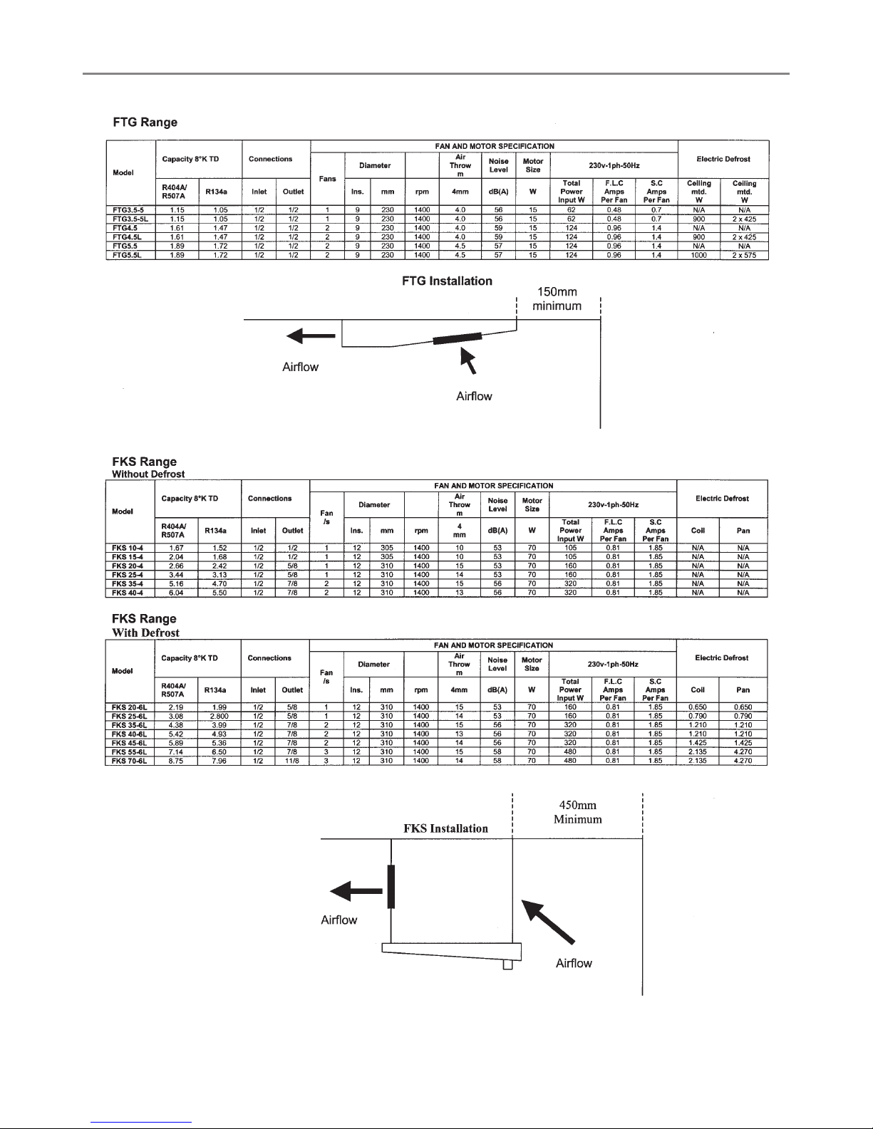
4. EVAPORATORS / COOLERS
FTG Range - Ceiling Mounted
These are used for small coldroom applications and are available for
both high and low temperature conditions. The low temperature models
have defrost heaters mounted under the coil block with access via the
drain pan. It will not be necessary to allow space at the side of the
Cooler for heater removal.
Positioning the Cooler should allow the discharged air from the finned
face to circulate around the coldroom. The rear of the Cooler can be
positioned close to the coldroom wall leaving sufficient space to remove
the drain pan. If the opposing wall is less than 600mm from the finned
face of the Cooler a curved air “deflector plate” should be used.
Fit the 1” BSP Drain Connector to the drain pan and connect the drain
line to it.
FKS Range.
These ceiling mounted Coolers are designed for medium/large
coldrooms for both high and low temperature applications.
The cooling air is discharged through the fan motors therefore it should
be positioned within the coldroom allowing at least 450mm clearance
between the rear finned face and the wall for air return to the Cooler.
If the opposing wall is less than 1.5m from the fan motors a curved air
“deflector plate” should be considered depending on model.
5. CONTROL PANEL
The Control panel is supplied with a main’s isolator switch, function
contactors, circuit breaker and a microproces sor temperature
controller complete with 10m long temperature sensing probes. The
air temperature sensing probe should be positioned in the return air
to the finned evaporator coil and the defrost termination temperature
sensing probes (when required) inserted at least 25mm into the finned
coil at the top.
See separate wiring diagrams for the various Condensing Unit /
13
Page 14

Foster Refrigerator
Oldmedow Road, King’s Lynn,
Norfolk PE30 4JU
England
Tel: 01553 691122
Fax: 01553 691447
Website: www.fosterrefrigerator.co.uk
E-mail: sales@foster-uk.com
a Division of ITW (UK) Ltd.
DUET/TM/05/05
T e c h n i c a l M a n u a l
 Loading...