

Page 1
Service Manual
ISO 14001
ISO 9001
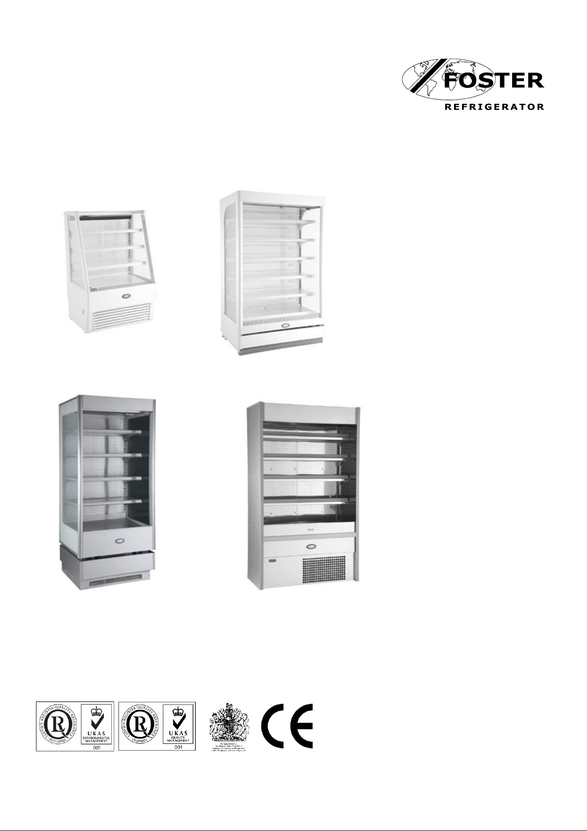
Display Case Service
Manual
Page 2

1
Contents
Environmental Management Policy
1
Disposal Requirements
1
User Operation
2
Alarms and Warnings
2
Information Menu
3
Service Access and Parameters
4
Parameter Definitions
3 to 5
Parameters
6 to 7
Probe Resistance Values
5
Technical Specification
7
Faults and Possible Solutions
8
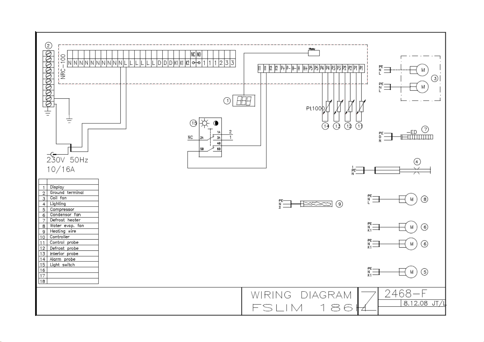
Wiring Diagrams
9 to 15
Environmental Management Policy for Service Manuals and Duets.
Product Support and Installation Contractors
Foster Refrigerator recognises that its activities, products and services can have an adverse impact upon the
environment.
The organisation is committed to implementing systems and controls to manage, reduce and eliminate its adverse
environmental impacts wherever possible, and has formulated an Environmental Policy outlining our core aims. A
copy of the Environmental Policy is available to all contractors and suppliers upon request.
The organisation is committed to working with suppliers and contractors where their activities have the potential to
impact upon the environment. To achieve the aims stated in the Environmental Policy we require that all suppliers
and contractors operate in compliance with the law and are committed to best practice in environmental
management.
Product Support and Installation contractors are required to:
1. Ensure that wherever possible waste is removed from the client’s site, where arrangements are in place all
waste should be returned to Foster Refrigerator’s premises. In certain circumstances waste may be disposed
of on the clients site; if permission is given, if the client has arrangements in place for the type of waste.
2. If arranging for the disposal of your waste, handle, store and dispose of it in such a way as to prevent its
escape into the environment, harm to human health, and to ensure the compliance with the environmental law.
Guidance is available from the Environment Agency on how to comply with the waste management ‘duty of
care’.
3. The following waste must be stored of separately from other wastes, as they are hazardous to the environment:
refrigerants, polyurethane foam, oils.
4. When arranging for disposal of waste, ensure a waste transfer note or consignment note is completed as
appropriate. Ensure that all waste is correctly described on the waste note and include the appropriate six-digit
code from the European Waste Catalogue. Your waste contractor or Foster can provide further information if
necessary.
5. Ensure that all waste is removed by a registered waste carrier, a carrier in possession of a waste management
licence, or a carrier holding an appropriate exemption. Ensure the person receiving the waste at its ultimate
destination is in receipt of a waste management licence or valid exemption.
6. Handle and store refrigerants in such a way as to prevent their emission to atmosphere, and ensure they are
disposed of safely and in accordance with environmental law.
7. Make arrangements to ensure all staff who handle refrigerants do so at a level of competence consistent with
the City Guilds 2078 Handling Refrigerants qualification or equivalent qualification.
8. Ensure all liquid substances are securely stored to prevent leaks and spill, and are not disposed of to storm
drains, foul drain, surface water to soil.
DISPOSAL REQUIREMENTS
If not disposed of properly all refrigerators have components that can be harmful to the environment. All old
refrigerators must be disposed of by appropriately registered and licensed waste contractors, and in accordance
with national laws and regulations.
Page 3

2
Ensure 20mm clearance between the
bottom of the shelves and the product.
Do not obstruct air channels
User Operation Guidelines
Start Up.
The cabinet is pre set at the factory to operate in normal ambient conditions and maintain the temperature in the
cabinet at -1+2 degrees.
Checking the temperature settings
Check the setpoint by pressing the FNC key briefly, Sett will be displayed, press the OK Key the setpoint value will
displayed.
Press the FNC key to return to normal temperature view or leave for 5 minutes to return automatically.
Defrosting
The cabinet will automatically defrost 6 times per day and when on defrost the controller will display
On completion the display will change to until the normal operating temperature
is achieved.
Alarms and Warnings
Thermostat probe failure. Call your Foster Authorised Service Company.
Evaporator probe failure. Call your Foster Authorised Service Company.
Air probe temperature failure. Call your Foster Authorised Service Company.
Safety switch probe failure. Call your Foster Authorised Service Company.
Safety switch probe failure. Call your Foster Authorised Service Company.
Safety switch is ON and cabinet lights are OFF (alarm signal). Indicates the condenser may need
cleaning. Switch the cabinet OFF, lift of the bottom front cover and clean the condenser using a
soft brush and a vacuum cleaner. Replace the cover and switch the power back on. If the
Interruption in the mains supply.
The cabinet will start automatically after a power cut
or an interruption in the power supply.
The vaporisation tray at the rear of the unit may
overflow during a power cut.
Loading the cabinet
When loading the cabinet ensure that the air is
retained with no obstruction to the airflow.
Do not place product in front of the inlet and outlet
grills and must not protrude over the front edges
of the shelves.
Improper loading will effect the operation of the
cabinet.
problem persists call your Foster Authorised Service Company.
Cabinet switches OFF due to overheating. Indicates the condenser may need cleaning. Switch
the cabinet OFF, lift of the bottom front cover and clean the condenser using a soft brush and a
vacuum cleaner. Replace the cover and switch the power back on. If the problem persists call
your Foster Authorised Service Company.
Controller
Page 4

3
Information Menu
Pressing and releasing FNC will access the information menu, use the UP or DOWN keys to scroll through and
press OK to display the value.
The first in the menu is Sett; this indicates the set value, press OK to display the value.
Release OK and Nd will be displayed; this indicates the next defrost time in hours and minutes, press OK to
display the value.
Release OK and Pb1 will be displayed; this is the temperature indicated by the Thermostat Probe, press OK to
display the value.
Release OK and Pb2 will be displayed; this is the temperature indicated by the Evaporator Probe, press OK to
display the value.
Release OK and Pb3 will be displayed; this is the temperature indicated by the Cabinet Probe, press OK to display
the value.
Release OK and Pb4 will be displayed; this is the first Condenser Alarm Probe, press OK to display the value.
Release OK and Pb5 will be displayed; this is the second Condenser Alarm Probe, press OK to display the value.
(Only used on models with two condensing units)
Release OK and Con will be displayed; this indicates which compressor is running. (Most cases have only 1
compressor but some have 2)
Release OK and C1t will be displayed; this indicates haw many hours the first compressor has been running.
Release OK and C2t will be displayed; this indicates haw many hours the second compressor has been running.
Press FNC to return to the main display.
User Menu
Press and hold FNC for 5 seconds to enter the user menu use the UP or DOWN keys to scroll through and press
OK to display the value.
See the cabinet parameters on page 4 for the correct settings.
Service Access and Parameters
To access press and hold OK for 5 seconds and the display will show 0000.
The password is 1953.
Set the first number by using the UP or DOWN key, once selected press OK to move to the next number.
Once the number is completed correctly press OK to access the parameters and use the UP and DOWN keys to
change the values. Once the change has been completed press OK to move to the next parameter.
Parameter Definitions
Set Point values for group 1- folder (St1)
St1 Set point value
The set point value for the first set of control parameters.
dlF1 Differential
The temperature difference for the stopping and starting of the compressor. Must be a positive value
dlt1 Time interval between defrosts
dEt1 Maximum duration of defrost.
dSt1 Temperature at which the defrost is terminated
dt1 Drying time after the termination of a defrost
Set Point values for group 2- folder (St2)
St2 Set point value
The set point value for the first set of control parameters.
dlF2 Differential
The temperature difference for the stopping and starting of the compressor. Must be a positive value
Dlt2 Time interval between defrosts
dEt2 Maximum duration of defrost.
dSt2 Temperature at which the defrost is terminated
Page 5

4
dt2 Drying time after the termination of a defrost
The group 2 values are only used on selected models.
Service Menu
Settings folder (Set)
SetC Parameter List
Set point value group for user menu 1 and 2
UloC Keyboard Lock
Locks the controller and disables the user menu and manual defrost.
St1 Set Point Value
Set point for the first control settings
SL1 Lower Set Limit
Minimum temperature set point for the first control settings
SH1 Upper Set Limit
Maximum temperature set point for the first control settings
C1 Compressor Mode
1 = One compressor: 1 = Two compressors: 3 = Compressor Cycling.
If more than one compressor is fitted both will run until the setpoint value is reached. After this the
compressor with the most operating hours stops. When the cabinet temperature rises and reaches the
restart temperature both compressors will run.
St2 Set Point Value
Set point for the second control settings
SL2 Lower Set Limit
Minimum temperature set point for the second control settings
SH2 Upper Set Limit
Maximum temperature set point for the second control settings
C2 Compressor Mode
1 = One compressor: 1 = Two compressors: 3 = Compressor Cycling.
If more than one compressor is fitted both will run until the setpoint value is reached. After this the
compressor with the most operating hours stops. When the cabinet temperature rises and reaches the
restart temperature both compressors will run.
dSnC Defrost synchronization
Probe folder (SEn)
SC Amount of Probes
The number of probes fitted to this model
dlSP Local Display
Allows the selection of a particular probe temperature to be displayed on the controller.
1 = Thermostat probe; 2 = Evaporator probe; 3 = Cabinet probe; 4 and 5 = Condenser alarm probes
dECP Resolution
Allows for a decimal point to be displayed.
0 = Not in use; 1 = in use
FC Filter Factor
This is a constant parameter used to stabilise the reading shown on the display. The value is always the
oFFS Display Temperature Offset
Allows for the cabinet probe and LCD display to be adjusted up or down to suit certain site requirements
C1Pd Condenser Overheat Probe 1
Selects the probe used.
same and it keeps the readings stabile.
Page 6

5
C2PD Condenser Overheat Probe 1
Selects the probe used.
Compressor Folder (CP)
d Defrost Mode
Selects the type of defrost used
0 = Electrical Defrost; 1 = Hot gas defrost
L on Min. Working Time
Minimum working time for the compressor
H on Max. Working Time
Maximum working time for the compressor
oFFt Compressor off-time
Compressor off time if maximum working time (H on) is achieved
CoFF Min. Down Time
Minimum down time of compressor
rAtE Cooling Rate
Percentage of the cooling frequency in probe failure
2dlF Compressor Difference (Not used)
Condenser Overheat Folder (OH)
AL Alarm Temperature
Temperature at which the condenser alarm will be activated
Alt Alarm Temperature Delay
Time in minutes that the alarm will be delayed
Sd Shutdown Temperature
Temperature at which the cabinet turns itself off due to high condenser temperature.
Sdt Shutdown Temperature Delay
Time delay before the cabinet shuts down due to too high condenser temperature
Net Folder (nEt)
nlD Device Identification
CAL1 Thermostat Probe Calibration
Calibration according to factory test run.
Standard Setting Folder (SdFt)
Press OK to restore the controller to the standard settings (NOTE; not the cabinet’s factory settings)
Page 7

6
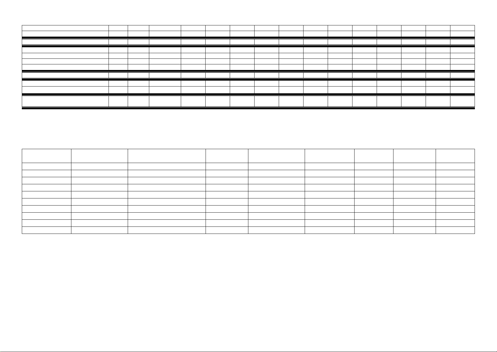
Foster Display Case Parameter Settings
Model
NRC100
Default
C1.0-15/08
FPREM
125HG
FPREM
195HG
FPRO
90HG
FPRO
130HG
FPRO
195HG
MINI
FM90
130HG
MINI
FM120
130HG
MINI
FM90
150HG
MINI
FM120
150HG
Slim
FS70
HW
Slim
FS90
HW
Slim
FS120
HW
User Menu
Temperature Set Point 1
(ST1)
Set Point Value
ºC
St1
-1
-1
-1
-1
-1
-1
-1
-1
-1
-1
+2
+1
+1
Differential
ºC
diF1 3 3 3 4 4 4 4 4 4 4 3 3 3 Defrost Interval
H
Dlt1 4 4 4 4 4 4 4 4 4 4 4 4 4 Maximum Defrost Duration
min
dEt1
35
35
35
35
35
35
35
35
35
35
35
35
35
Defrost End Temperature
ºC
dSt1
11
11
11
11
11
11
11
11
11
11
11
11
11
Drain Down Time
min
Dt1 0 0 0 0 0 0 0 0 0 0 0 0 0 Temperature Set Point 2 (if in use)
(ST2)
Set Point Value 2
ºC
St2
-20
Differential 2
ºC
diF2 2 Defrost Interval 2
H
dit2 6
Maximum Defrost Duration 2
min
dEt2
45
Defrost End Temperature 2
ºC
dSt2
11
Drain Down Time 2
min
dt2 0
Service Menu
Settings Folder
(SEt)
Parameter List
SetC 1 1 1 1 1 1 1 1 1 1 1 1 1 Keyboard Lock
UlocC 0 0 0 0 0 0 1 1 1 1 0 0 0 Setpoint Value
ºC
St1
-1
-1
-1
-1
-1
-1
-1
-1
-1
-1
+1
+1
+1
Lower Set Limit
ºC
SL1
-2
-2
-2
-2
-2
-2
-2
-2
-2
-2
-2
-2
-2
Upper Set Limit
ºC
SH1
10
10
10
10
10
10
10
10
10
10
10
10
10
Compressor Mode
C1 1 2 2 1 1 2 1 1 1 1 1 1
1
Setpoint Value 2
ºC
St2
-20
-20
-20
-20
-20
-20
-20
-20
-20
-20
-20
-20
-20
Lower Set Limit 2
ºC
SL2
-30
-30
-30
-30
-30
-30
-30
-30
-30
-30
-30
-30
-30
Upper Set Limit 2
ºC
SH2
10
10
10
10
10
10
10
10
10
10
10
10
10
Compressor Mode 2
C2 1 1 1 1 1 1 1 1 1 1 1 1
1
Defrost synchronization
dSnC 0 0 0 0 0 0 0 0 0 0 0 0
0
Probe Folder
(SEn)
Amount of Probes
pcs
SC 4 4 5 4 4 4 4 4 4 4 4 4 4 Local Display
dlSP 3 3 3 3 3 3 3 3 3 3 3 3
3
Resolution
dECP 0 0 0 0 0 0 0 0 0 0 0 0 0 Filter Factor
FC 7 7 7 7 7 7 7 7 7 7 7 7
7
Display Temperature Offset
oFFS 0 0 0 0 0 0 0 0 0 0 0 0 0 Condenser Overheat Probe 1
C1Pd 4 4 4 4 4 4 4 4 4 4 4 4 4 Condenser Overheat Probe 2
C2PD 4 4 5 4 4 4 4 4 4 4 4 4
4
Compressor Folder
(CP)
Defrost Mode
d 0 0 0 0 0 0 0 0 0 0 0 0 0
Min. Working Time
min
L on 0 0 0 0 0 0 0 0 0 0 0 0 0 Max. Working Time
min
H on
60
60
60
45
45
45
60
60
60
60
60
60
60
Compressor off-time
min
oFFt 5 5 5 5 5 5 5 5 5 5 5 5 5 Min. Down Time
min
CoFF 2 2 2 2 2 2 2 2 2 2 2 2
2
Page 8
7
Cooling Rate
%
rAtE
70
70
70
70
70
70
70
70
70
70
70
70
70
Compressor Difference
2dlF 2 2 2 2 2 2 2 2 2 2 2 2
2
Condenser Overheat Folder
(OH)
Alarm Temperature
ºC
AL
50
50
50
47
47
47
50
50
50
50
47
47
47
Alarm Temperature Delay
min
Alt 2 2 2 2 2 2 2 2 2 2 2 2 2 Shutdown Temperature
ºC
Sd
55
55
55
52
52
52
55
55
55
55
55
55
55
Shutdown Temperature Delay
min
Sdt 0 0 0 0 0 0 0 0 0 0 0 0
0
Net Folder
(nEt)
Device Identification
nlD 0 0 0 0 0 0 0 0 0 0 0 0
0
Thermostat Probe Calibration
CAL1
-*
-*
-*
-*
-*
-*
-*
-*
-*
-*
-*
-*
-*
Return NRC-100 Default settings
NOTE: Not Cabinet Settings
SdFt
- - - - - - - - - - - - -
-
*) Calibration according to factory test run.
Model
Compressor cm3
Total Power Input (W)
(Thermal Heat Rejection)
Run Amps
Compressor Run
Watts
Compressor
Start Current
Fuse
kWh/24h
dB (A)
PREM 125
15 + 15
2022
10.8
1360
20A*
13A
43.0
<59
PREM 195
18 + 18
2934
14.8
1800
20A*
16A
63.2
<59
PRO 90
18
1688
8.3
900
20A
13A
35.8
<59
PRO 130
21
2058
9.9
910
20A
13A
43.9
<59
PRO 195
14 + 14
2954
14.8
1360
20A*
16A
63.7
<59
SLIM 70
10
1248
6.4
460
20A
13A
25.5
<56
SLIM 90
14
1468
7.4
680
20A
13A
30.1
<56
SLIM 120
18
1710
8.4
900
20A
13A
35.1
<56
MINI 90
14
1414
7.1
680
20A
13A
29.5
<56
MINI 120
18
1684
8.3
900
20A
13A
35.3
<56
**) Gas Defrost = 1
***) Gas defrost = 0
****) Gas defrost = 15
Technical Specification
* For cabinets with 2 compressors fitted there is a 20 second delay between compressor starts so the start current of 20A is not exceeded.
The suction pressure as per climate class 3 (see below) is between -8 and -10 ºC approximately 3.5 bar, with a discharge temperature of +40 ºC (clean condenser)
approximately 17.3 bar.
The cases are designed to work in an ambient temperature not exceeding 25 degrees centigrade (C) with a relative humidity not exceeding 60% (RH) Climate Class 3.
The frontal airflow should be < 0,2m/s
Probes
The probes used are PT-1000 with rating at 0º C of 1000 Ohms. There is not a temperature range but the resistance value is approximately 950 Ohms at - 10º C and 1200
at + 50º C.
Page 9

8
Case Faults and Possible Solutions
No
Problem
Possible Cause
Solution
1
Display Shows
ERR1
ERR2
ERR3
ERR4
ERR5
Probe Failure, Probe with the same
number broken or has a bad
connection
1 = Thermostat Probe
2 = Defrost Probe
3 = Cabinet Probe
4 = Condenser Overheat Probe
5 = Condenser Overheat Probe
Check connection or change
probe.
2 Display shows Err6 and the
cabinet lights are off
= Condenser Overheat Alarm
Indicates dirty condenser or
condenser motor failure.
Condenser blocked or cabinet to
close to the wall
Check / Clean condenser
Change fan motor
Check for sufficient clearance at
rear of machine
3
Display Shows Off
= Cabinet shut down due to
condenser overheat
Indicates dirty condenser or fan motor
failure.
Check Condenser cleanliness
Check condenser fan motor and
refrigerant circuit function
4
Display shows off when
plugging in the cabinet after
changing the controller
1) Parameter C2Pd in SEn folder set
wrong. Value should be 4 when
cabinet with 1 condenser (=4 probes).
NOTE! Off-text appears with 1-2 min
delay after starting up the cabinet.
2) Parameter Sdt (shut down delay) is
set to 0 min. NOTE! Off-text appears
directly after starting up the cabinet
3) Probe 4 or 5 broken or badly
connected. NOTE! Err 4 (or Err 5) text
appears directly after plugging in the
cabinet. Off-text appears with 1-2 min
delay
1) Change parameter C2Pd to 4
2) Change parameter Sdt to 1
3) Change probe/s 4 or 5. Check
connection
5
Display shows 8888 or shows
nothing
1)Start Failure
2) Display or display cord failure
3) Controller failure
NOTE! Start failure fixed in NRC100 with software version C1.0 or
later (manuf. date 15/08 or later)
1) Disconnect the cabinet and
plug in again.
2) Change display or display cord
3) Change controller
6
Display shows radically other
value than 0…5º under normal
running conditions
1) Cabinet set too cold
2) Other probe than cabinet
temperature probe (e.g. 3) showing
on the display
3) Probes incorrectly connected
1) Change St1 value
2) Check parameter dlSP (cabinet
temperature = 3)
3) Check connections
7
Compressor Cut-in and Cutouts not following Set-value
(and the differential)
Cabinet running on minimum running
time(Lon) and minimum stop time
(CoFF)
If the cabinet temperature is OK
there is no need for service.
If the products is too cold raise
the set value, and if necessary
increase the differential
8
Parameter values not possible
to set as whole numbers
(e.eg. 1.0, 2.0, 3.0 and so on
Controller malfunction
Change controller
Page 10

9
Page 11

10
Page 12

11
Page 13

12
Page 14

13
Page 15
14
Page 16

15
Page 17

16
Foster European Operations
France
Foster Refrigerator France SA
Tel: (33) 01 34 30 22 22. Fax: (33) 01 30 37 68 74.
Email: commercial@fosterfrance.com
Germany
Foster Refrigerator Gmbh,
Tel: (49) 781 990 7840. Fax (49) 781 990 7844.
Email: info@foster-gmbh.de
Foster Refrigerator
Oldmedow Road
Kings Lynn
Norfolk
PE30 4JU
Tel: 01553 691122
Fax: 01553 691447
Website: www.fosterrefrigerator.co.uk
Email: sales@foster-uk.com
a Division of ‘ITW (UK) Ltd’
Foster Display Case/SM 03/09
 Loading...