

Foster Faust 90 7167-042, Faust 90, 7167-042 Installation, Operating And Maintenance Manual
Page 1
18
7167-042
“Faust 90” multifunctional oven
Installation, operating and maintenance manual
GB
Page 2

19
PRECAUTIONS FOR SAFE OPERATION
• This manual constitutes an integral part of the appliance; it must be stored intact for
future reference for the entire oven lifecycle. Carefully read this manual prior to
using or installi ng th e appl ian ce .
• This oven is designed for domestic use only and is intended for cooking and
warming foodstuffs. Any other use (e.g. warming of the room) constitutes
improper use and is dangerous. The manufacturer shall not be held liable for any
consequences resulting fr om alternative use of the oven.
• The various packaging components must not de disper sed into the environment, but
disposed of in compliance with the legislation in force concerning waste disposal.
• Installation must be carr ied out by qualified personnel in conformity to the
regulations in force.
• In the event that the appliance malfunctions, disconnect it from the power supply
and contact the nearest Foster technical assistance centre.
Observe the following for correct use of the oven:
- This appliance is intended for use by adults - keep children out of reach.
- Do not introduce inflammable objects in the oven as these may cause fire.
- The appliance generates heat, therefore limit contact with its ou ter surface and
absolutely avoid touching the internal parts.
- Grip the handle in the cen tre to ope n the do or cor re c tly .
- Always use oven gloves when introducing or removing foodstuffs into/from the
oven.
- Do not obstruct the oven's ventilation and heat diss ipation openings.
- Do not place heavy obj e ct s on the op en do or as t hes e coul d damage the hinges.
- Do not hang any heavy object from the oven door handle.
- Do not pull on the power cable to unplug the appliance.
Observe the following to save energy:
- Pre-heat the oven only for the t ime strictly required.
- Use dark-coloured oven cookware items as they absorb heat more effecti vely.
- Open the oven door only whe n strictly necessary so as to avoid dispersing heat.
- Keep the gaskets clean and fully efficient in order to prevent heat dispersal.
- Always make sure the oven is turne d off afte r use.
THE MANUFACTURER DECLINES ANY CIVIL AND CRIMINAL LIABILITY
SHOULD THE ELECTRICAL CONNECTIONS NOT BE CARRIED OUT IN
CONFORMITY TO THE LAWS IN FORCE AND THE INSTRUCTIONS
CONTAINED HEREIN.
Page 3
20
INSTALLATION INSTRUCTIONS
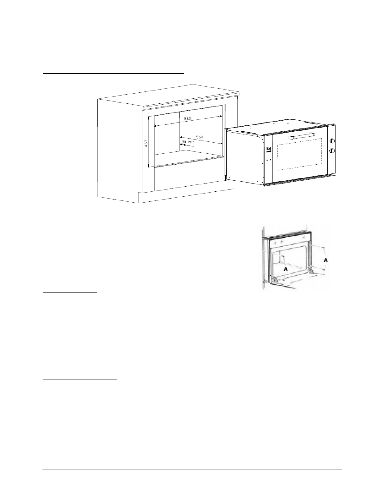
Installing the built -i n ov en in t o the ca bine t
The oven
can be
installed
either on
column
cabinets or
beneath
cabinet
worktops.
The cabinet
recess must
have the
following
dimensions: 865x467 mm.
An opening must be cut into the back of the oven cabinet or
support shelf (towards the rear) to ensur e adequate air flow
and ventilati on for the oven to co ol du ri ng op era ti on.
Make sure that the oven is safely instal led in the cabinet. Use
the 4 screws (A) to secure th e ove n.
Cabinet features
The cabinet must have the fo llowing features:
• The cabinet and related components must be able to withstand a te mperature of
150°C without deforming a nd/or surface defects appea ring.
• The cabinet must not interfere with the passage of electrical wiring.
• The cabinet housing the oven must have a load capacity of 70 kg.
Electrical connections
IMPORTANT:
• The electrical connections must be carried out by a qualified and/or authorise d
electrician on ly.
• The electrical connection must be carried out in conf ormity to the European
regulation s in force.
• The electrical connection required is a single-phase 220-240 V, 50-60 Hz type
connection (check the pr oduct's rating plate regarding the corre ct supply voltage
and frequency).
Page 4
21
IT is mandat ory to earth the appliance:
• If the appliance is directly conn ect e d to the m ains ele c tr ici ty, an omnipolar swi tc h
with contact gap of at least 3 mm - able to withsta nd th e ove n' s pow er o ut pu t must be installed between the oven and power socket.
• The earth wire must by no means be interrupted by the omnipolar switch.
Always ensure that the oven is disconnected from the power supply before effecting
maintenanc e work and/or adjustments.
The oven may be supplied without a plug fitted on the power cord. If this occurs, ch oose
a plug that ca n withstand t he oven's maximum power output. Make sure that the eart h
wire (yellow/green) is pr operly connected to the relative plug pin.
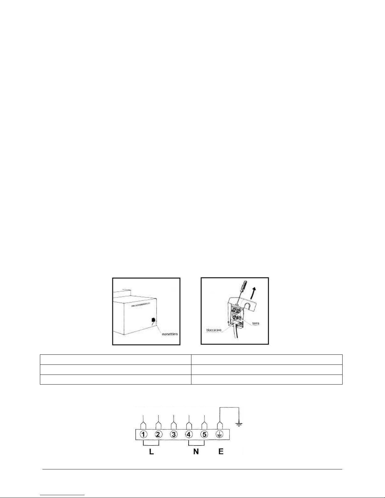
Follow the steps below when connecting or replacing t he power cable:
• Disconnect the a ppl ia nc e or the powe r su p ply .
• Open the terminal board cover.
• Connect the ends of the powe r ca ble - rem ember that the earth wire is identified by
the yellow/green jacket. If using a BS 1363-approved 13 A plug, apply a 13 A fuse.
• The power ca ble must be secured by the cable clamp on the terminal board to
prevent it from turning and/or detaching. No point of the cable must be exposed to
temperature s exc e ed i ng 75 °C.
• The plug conne cting the appliance to the mains electricity must be s uitable for the
oven's power output. Moreover, the plug must be easily accessible once the oven
has been installed. An omnipolar switc h with a contact gap of at least 3 mm must
be installed in the event of a direct connection to the mains elect ricity.
morsettiera
terminal board
bloccacavo
cable clamp
terra
earth
Page 5

22
WARNING:
use a flexible three-wire cable - type H05RR-F (3x1.5 mm).
Page 6
23
OPERATING INSTRUCTIONS
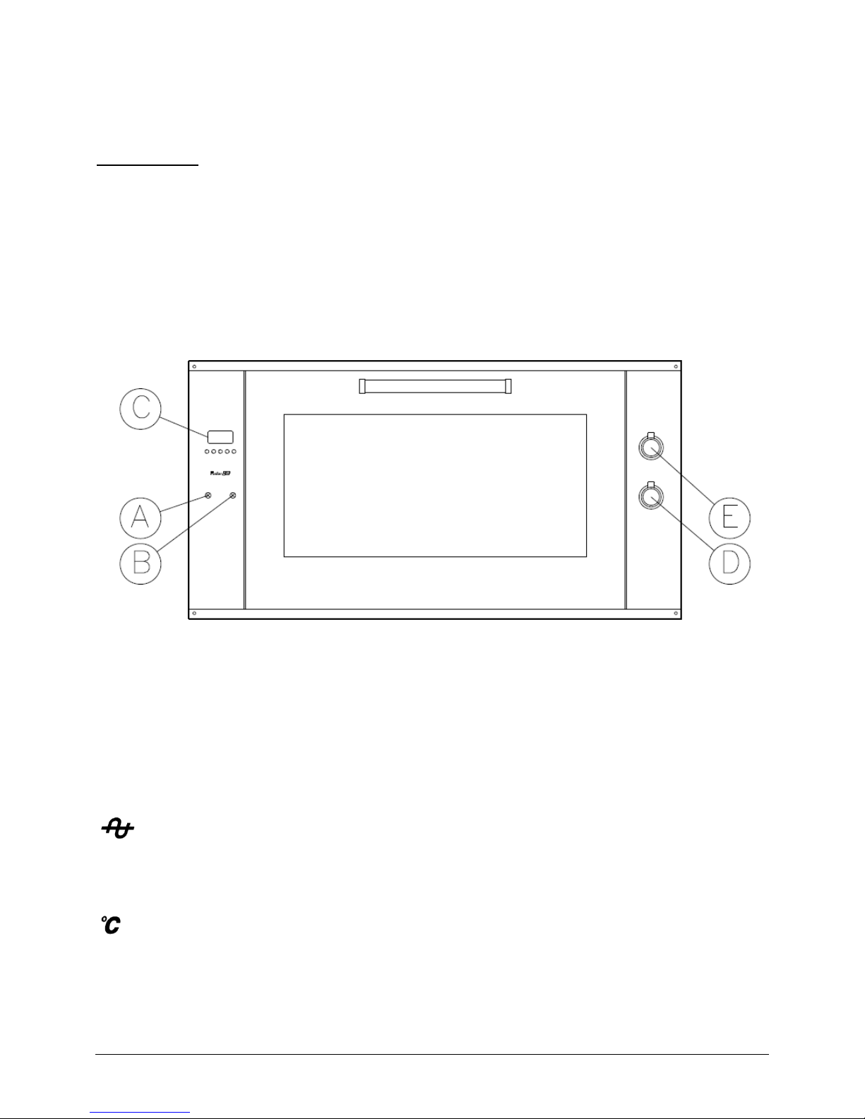
Control panel
A = ON/OFF (power indicator light)
B = ON/OFF (thermostat indicator ligh t)
C = electronic programmer (5 buttons)
D = oven temperature therm os tat kn o b
E = commutator or function selector knob
IMPORTANT:
prior to first use, turn on the oven at maximum power and operate it f or maximum 1 hour
while empty. Aerate the r oom well and open the kitchen windows if necessary. This
ensures that a ny combustion fumes of production residues such as grease, oil and
processing resin can escape.
ON/OFF (powe r indicator light)
When turned on, it indic a te s tha t the ov en i s ele ctr ic a l ly power e d.
ON/OFF (the rmostat indicator light)
Indicates the tur n ing on / off of the he at i ng elements to maintai n the se lected cooking
temperature.
Page 7

24
Electronic programmer
The clock shows the time up to 23 h : 59 min.
End-of-cooking tim e up to 23 h : 59 min., timer up to 23 h : 59 min., cookin g time of 10
h.
Functions
Cooking time
C, end-of-cooking time S, time, timer B, minus -, plus +, manual se le c tion
C - S, automatic p rogramme A, manual mode .
Display
4-digit, 7-segment display for the time of day. Allows f or checking the remaining
cooking time .
Setting the time
Select a func tion by pressing the relat ive button and set the time using buttons
+ and -.
Plus/minus (
+ / -) buttons
Pressing button
+ increases the time while pressin g - decr eases it. Scroll the digits rapidly
by pressing and holding either button.
Setting the clock
Select the “set clock” fun ction by sim ultaneously pr essing
C and S while setting the time
with buttons
+ and -. This operation cancels the previously set cooking time programme
and disenga ges the manual mode.
Manual operat ion mo de
This function allows for using the oven continuously. Simply press buttons
C and S
simultaneously on the electronic progr ammer. T he control relay will activate. The letter
“
A” (automatic) will disappear from the display and the pot symbol C will appear. Any
previously set programme will be cancelled.
Semi-automatic operation mode with end-of-cooking time
Select function
C and set the e nd-of-cooking time using buttons + and -. The symbol
“
A” and the pot symbol C will appear on the display, thereby activating the power
switch. When the clock reaches the programmed end-of-cooking time, a buzzer sounds
and the symbol “
A” will flash intermittently; symbol "C" and the heating element will
then turn off and the oven will stop operating.
Page 8

25
Automatic operation mode
Select function
C and set the c ooking time using buttons + and -. The symbol “A” and
the pot symbol
C will appear on the display, thereby activating the p ower switch. Select
function
S and the end-of-cook ing time will ap pear. Set the e nd-of-cooking time using
buttons
+ and -. The power switch and pot symbol will disengage. The pot symbol will
reappear when the clock rea ches the programmed star t-of-cooking time.
At this point, insert the foodstuff in the muffle, select the desired cooking function a nd
programme the cooking temperature. A t the end of the automatic mode, the symbol “
A”
will flash. A buzzer will sound and the power switch and pot symbol will disengage.
Timer
Select button
B and set the required time using buttons + and -; the bell sy mbol will
appear on the display. A buz zer sounds once the programmed time is reached.
Buzzer
The buzzer (1 Hz, intermittent) sounds for 7 minutes at the end of the programmed time.
Any button can be pressed to stop the buzzer. While the buzzer sounds, the frequency of
the sound can be adjusted by pressing and holding
- (“minus” button). Thr ee differen t
frequencies can be selected.
Programme start and check
Each pre-set programme activates only once the cooking time has been set. The start time
can be checked any moment by selecting the previously programmed function.
Identifying programming errors
Incorrect pr ogramming occurs if the time of day falls within the programmed cooking
period - i.e. between the start and end of cooking time. In the event of incorrect
programming, a buzzer sounds and the symbol “
A” will flash. T he error can be r ectified
by modify ing one of the two c ooking times.
Cancelling a programme
A cooking programme can be ca ncelled by selecting the manual mode. Like wise, when a
pre-set programme terminate s autonomously, it is automatically cancelled for future
operations.
Page 9

26
Oven temperature thermostat
The oven temperature ther mostat contro ls the de sir e d co oki ng t em pe ra tur e for all th e
oven's operating selections. The heating elements turn on/off to maintain the programmed
temperature.
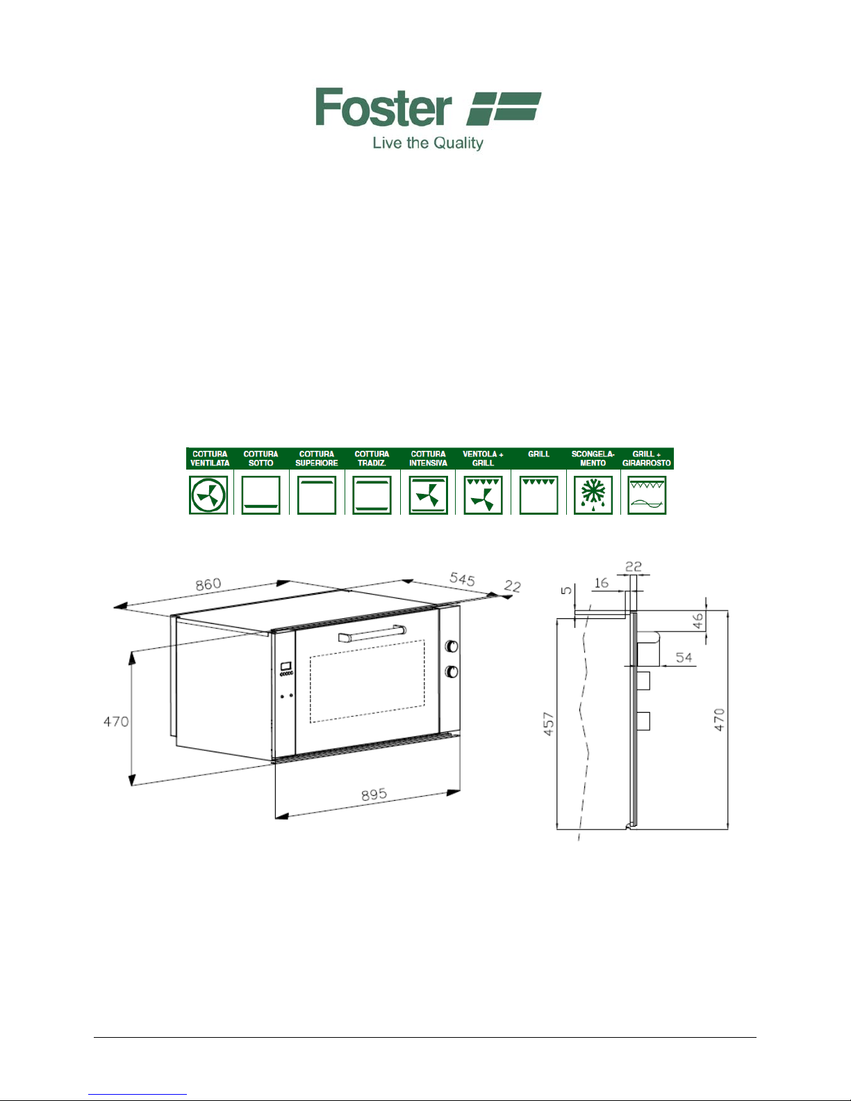
Commutato r or oven function selector
This commutator activat es the desired cooking function. The illustration bel ow shows the
heat source and heat distribution for each selected operating mode. The lower and circular
heating elements are housed in the bottom and rear e nd of the muffle respectively. The
heating elements turn on /off automa tically to maint ain the desired cooking temperature.
Oven lamp
Use this function to turn o n the oven lamp. The lamp remains lit with th e other functions
as well.
Regular static cooking
Use this function for regular cooking or for roasting. The uppe r and lower heating
elements heat the air.
Page 10

27
Bottom-end cooking
Use this function to roast foodstuffs from below. The intense heat generated is ideal for
roasting meat that is not particularly tender.
Top-end cooking
Use this function to roast foodstuffs from above. The intense heat generated is ideal for
cooking and browning foodstuffs.
Grill
Use this function for grilling foodstuff s.
Select the grill function on the comm utator and position the thermostat on the maximum
temperature setting. Pre-heat the muffle before introducing the foodstuff. Use t he grill
function for maximum 15 minutes and always with the oven door open.
WARNING:
accessible parts may over heat while the grill mode is activated. K eep children at a safe
distance.
Rotisserie gri ll
Use this function for grilling with the a id of a spit. It i s advisable to pre-heat
the oven usi ng the grill mode prior to us ing
this function. Insert the spit with the
foodstuff in the ap pr opr i ate h ub th en la y it
on the spit support. Positi on the drip pan
beneath the foodstuff. Remember to
remove the spit grip prior to the start of
cooking.
Page 11

28
Ventilated grill
Use this function to grill with the addition of hot air.
Intensive cooking with hot air
Use this function to roast or cook foodstuffs with the aid of hot air. The upper-end and
lower-end cooking with hot air produces a crisp fini sh on foodstuffs.
Intense cooking with hot air
Use this function to achieve uniform cooking. The ideal cooking mode for baking cakes,
bread and other lar ge -si zed foodstuff s.
Thawing and drying
Use this function to accelerate thawing and/or drying of foodstuffs to be cooked, with the
aid of forced air flow.
Page 12

29
Oven grid positions for specific cooking needs
• Frozen cakes, long roast s, turkey, cakes, well-done steak: positions no. 1 and 2
from bottom.
• Cakes, sandwich bread slices, toasts, foodstuffs in saucepans, w hole-grain bread,
meat: position no. 2 from bottom.
• Biscuits, thin-sliced meat: position no. 3 from bottom.
• For browning with the grill mode, use p osition no. 3 from bottom.
WARNING:
the oven may reach very high temperatures during operation. Be ca reful not to touch the
heating elements inside the oven.
Page 13

30
MAINTENANCE INSTRUCTIONS
Cleaning the ove n
Cleaning safety
Turn the oven off and wait u ntil all the heating elements have cooled down before
touching or cleaning them. Clean the appliance with care.
Cleaning the oven surface
Clean using a damp cloth wetted with non-abrasive detergent t hen wipe with a soft dry
cloth. Stai nless steel surf aces with cru sty residues must only be cleaned using a plastic
scraper or sponge wetted with vinegar and warm water .
WARNING: do not use steam-cleaners for cleaning any part of the oven.
Oven door
Follow the instructions below for removing and rein serting the oven door.
Removing the oven door
Open the oven door fully. Lift the hinge hook and shift it into the
indentation on both hinges. This will prevent the hinges from
closing suddenly while removing the door. Grip the door by the
sides towards the hinge area. Raise the door by a few ce ntimetres
(the spring will offer some resistance due to the locked hinge).
Once the door has bee n suff ic ie nt ly raised, the hinges can be
dislodged from their housings. Remove the hinges from the
openings on the door frame.
Lower the hinge
hook after
inserting the door
Lift the hinge hook and shift it Hinge hook
into the locking indentation to remove
the oven door
Reinserting th e ove n do o r
Grip the door by the sides towards the hi nge area and insert the hinges into the openings
of the oven' s front frame . Disengage the locking hooks w hile keeping the door fully open.
Page 14

31
Lift the oven door and ensure that is has been properly inserted and aligned with the side
edges.
WARNING:
do not remove the lockin g hooks from their housing on ce the door has been removed. Do
not close the hinges without the weight of the door countering them, or else the powerful
springs will cause the hinges to close vi olently.
CAUTION:
do not lay he avy objects on the door or st and on it. This may cause the door to break or
harm the user. Moreover, do not use the ov en until the do or has been properly reinserted.
Removing the internal gl ass plate of the oven door (4 screws)
Replacing the ov en la mp
WARNING:
in order to prevent electric shocks an d/or harm to persons, read and follow the procedure
below.
Prior to replacing the ov en lamp, verify that the mains electrici ty
has been disconnected by pressing the mains switch.
Make sure that the oven and lamp are both cold. Next, unscrew and
remove the lamp cap “A”.
Do not touch the hot lamp with a damp cloth as the lamp itself may
shatter.
Replace the lamp with a 25 W lamp suitable for household
appliances (for 220-240 V AC operation).
If the lamp cap is damaged or broken, do not use the ove n until it has been properly and
safely replaced or reinserted.
Page 15

32
Spare parts
Only authorised spare parts may be used for carrying out technical interventions on the
appliance. All repairs or technical intervention s must be carried out by authorised and
qualified per son ne l.
Spare parts can be ordere d by contacting the nearest authorised technical assistance centre
(consult the list on the "w arranty guide") and indicating the following data:
• Oven serial number and model number, which can be fou nd on the label placed on
the lower front side of the muffle.
• Details of the dealer from which the oven was purchased.
Page 16

33
OVEN SPECIFICATIONS
Electrical data
Voltage
220-240 V, 50-60 Hz
Total power output
2.6 kW
Upper heating el ement
0.8 kW
Grill heating element
1.8 kW
Lower heating element
1.2 kW
Circular heating element
2.5 kW
Oven lamp
2 x 25 W
Oven fan
25 W
Tangential ove n fa n
25 W
Muffle work in g dimen sions
Height
305 mm
Width
580 mm
Depth
410 mm
Grilling surface
700 cm2
Energy consumption
necessary to reach 200°C
0.60 kW/h
necessary to maintain 200°C
0.81 kW/h
Total consumption power
1.41 kW/h
General features
• Foster model no.: 7167-042
• front external dimensions: 895 x4 70 m m
• recess dimensions: 865x467 mm
• standard features: grid, e namelled drip pan, spit
• 8 operating programmes
• tangential fan
• electronic programming of s tart and end of cooking time with digital display
• working volume: 73 litres
• energy class: A
• triple-glazed door
This oven is manufactured in conformit y to the following European directives:
- 2002/40/EC (Energy Labelling Directive)
- 2004/108/EC (Electromagnetic Compatibility Directive)
- 2006/95/EC (Low-Voltage Directive)
Page 17

34
END-OF-LIFE PRODUCT DISPOSAL
This product conforms to European Dire ctive 2002/96/EC.
The crossed-out dustbin symbol appearing on the appliance indicates t hat the end-of-life
product must be treated separately from domestic household waste and delivered to a
separated w aste collection facility for electric and electronic equipment, or returned to the
dealer when purchasing a new applianc e of the same kind.
The user is responsible for delivering the end-of-life product to an appropria te waste
collection facility and, should this not occur, will be subject to the relative penalties
specified by the waste disposal legislation in force.
Proper separ ate disposal of the decommissioned pr oduct and its eco-compatible
recycling, tre atment and scrappi n g con tri bu te s to pre ve nt i ng pos s ib le neg at iv e eff ec t s on
the environment and human health, and favours the recycling of the materials comprising
the product.
For more detailed information on the available waste collection systems, conta ct your
local waste disposal serv ice or the dealer from which the product was purchased.
Foster S.p.A.
via M.S. Ottone, 18/20 – 42041 Brescello (RE) – Italy
www.fosterspa.com info@fosterspa.com
After-sales service: Tel. +39 0522-684450; Fax +39 0522-686019,
service@fosterspa.com
Spare parts service: Tel. +39 0522-684300; Fax +39 0522-684300
 Loading...