

Page 1

Installation Instructions
GB
Operating instructions
Packaged Coldroom
Page 2
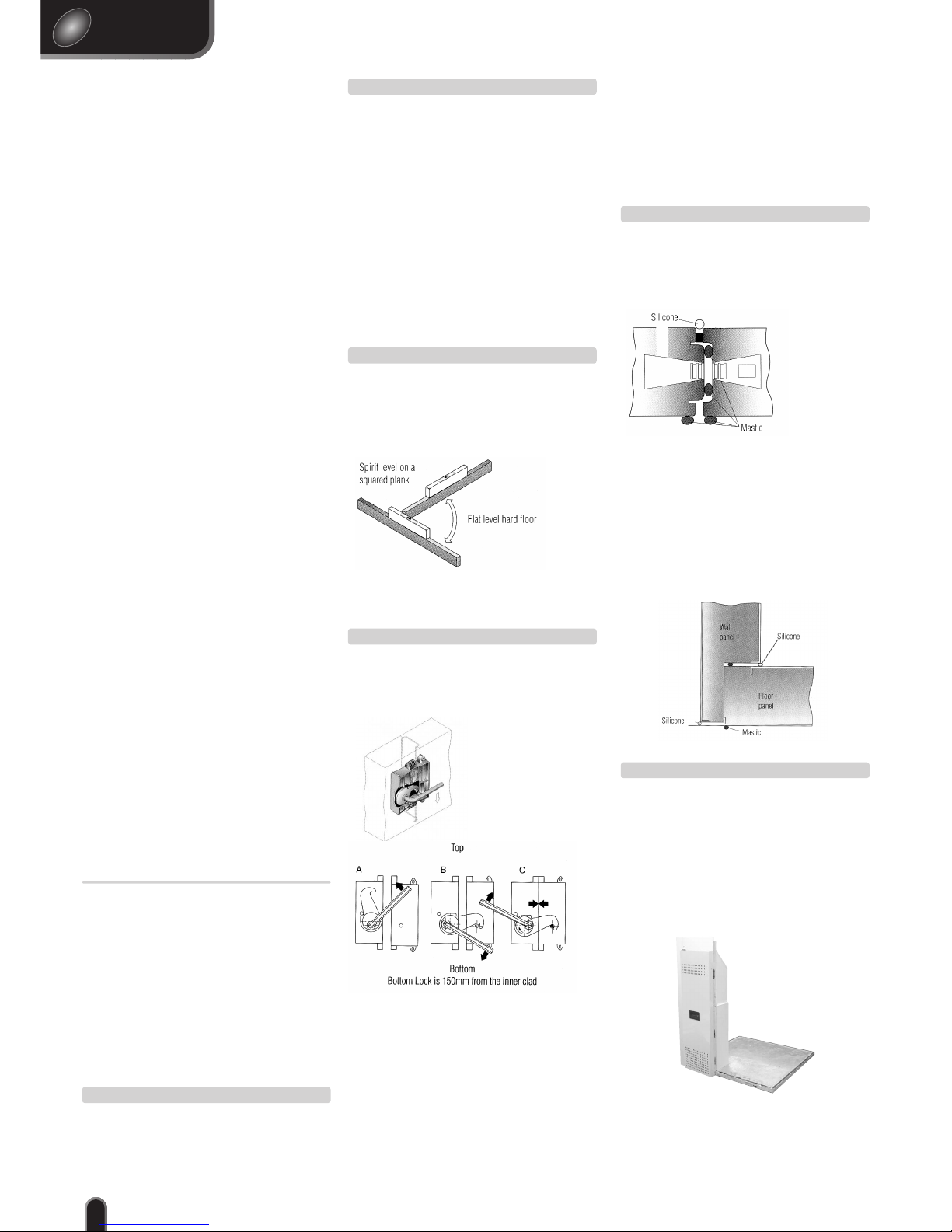
Figure 2 Fosterlok
Panel Locks
Foster coldroom panels lock together with an
effective locking system (fig 2).
STEP 4.
english
GB
Important
Disposal
Requirements
If not disposed of properly all refrigerators have
components that can be harmful to the environment. All old refrigerators must be disposed of
by appropriately registered and licensed waste
contractors, and in accordance with national
laws and regulations.
Figure 4
Floor/Floor
joint
Figure 6
Figure 1 Spirit level
on a squared plank
Preparation
Prior to commencing the installation familiarise
yourself with the entire assembly procedure
including joining methods and sealing.
2
STEP 1.
Uncrating
1. Check the crates or packaging for damage. If
damaged inform the lorry driver, note the delivery
number, inform the factory immediately (or your
insurance company, if outside the UK).
2. Remove crate or packaging carefully. Never use
the coldroom panels as a lever point for crowbars.
3. The panels are loaded onto the pallet in
sequence for easy assembly with one of the floor
panels at the top, beneath that is the door and
door jamb. Remove the floor panel and place to
one side followed by the door and jamb.
4. It is suggested that the remaining panels be left
on the pallet until required.
5. The refrigeration system panel is packed
separately and should be left on the panel until
required.
STEP 2.
Floor Preparation
The floor that the coldroom is to be erected
on must be clean, dry and flat.
The floor must be level within ± 3mm.
If the floor is not level the wall and ceiling panels
will not lock correctly. Check the floor using a
spirit level on a 2-metre plank, pointing the plank
both along and across the floor.
STEP 3.
Floor Panels
Fit the floor panels with the patterned side up
and the smooth side down.
Ensure sub-floor is smooth, flat, level and hard.
Before laying the first floor panel into position apply a
bead of mastic as shown to all outer perimeter edges
of the panel, (fig 1) ensuring a moisture seal between
the insulated floor panel and the sub-floor.
Follow the same procedure for the second and any
subsequent floor panels but also apply two beads of
mastic to the female extrusion (fig 1) prior to locking
panels together.
NOTE: Packing is not advised to adjust insulated
floor panel levels.
Do not use sand as a sub-floor base.
STEP 5.
Refrigeration
System Panel
Transport the refrigeration panel on its pallet as
close as possible to the point of installation.
Apply mastic to the top edge of the floor, female
side and the top of the 'L' shaped section of the
panel (see fig 5). Manoeuvre the panel into
position.
Carefully slide the refrigeration system panel
approximately into place as the corner, when
fitted, will determine the final position.
Avoid pressing against the hinged cover as this
could result in damage to it.
NOTE: the bottom lock is always 150mm
(6inches) from the floor on all corner and
wall panels
STEP 6.
Figure 5 Wall/Floor joint
It is important that the installation
instructions are read through and thoroughly understood before commencing
the installation of the coldroom.
Follow the step by step guide ensuring
that each stage of the installation is
followed correctly as failure to do so
could effect the operation of the unit
and may result in the warranty agreement being invalidated
Environmental Management Policy
Product Support and Installation Contractors
Foster Refrigerator recognises that its activities, products and
services can have an adverse impact upon the environment.
The organisation is committed to implementing systems and
controls to manage, reduce and eliminate its adverse environmental impacts wherever possible, and has formulated
an Environmental Policy outlining our core aims. A copy of
the Environmental Policy is available to all contractors and
suppliers upon request.
The organisation is committed to working with suppliers
and contractors where their activities have the potential to
impact upon the environment. To achieve the aims stated in
the Environmental Policy we require that all suppliers and
contractors operate in compliance with the law and are
committed to best practice in environmental management.
Product Support and Installation Contractors are
required to:
Ensure that wherever possible waste is removed from the
client’s site, where arrangements are in place all waste
should be returned to Foster Refrigerator’s premises. In
certain circumstances waste may be disposed of on the
client’s site, if permission is given, where the client has
arrangements in place for the type of waste.
If arranging for the disposal of your waste, handle, store
and dispose of it in such a way as to prevent its escape into
the environment, harm to human health, and to ensure the
compliance with environmental law. Guidance is available
from the Environment Agency on how to comply with the
waste management 'duty of care'.
Ancillary Items
Floor Plugs CMFOS1XT826 GREY
Floor Plug Pins CMFOS1XT827 GREY
Mastic Hansil 580 Grey 400ML
Key Hexagonal 8MM A/F Coldroom Panel
Coldroom Warning Label (Roof)
Plugs LD POLY White BPLDP1/2"
Silicone Sealer White 310ML
Silicone Sealer Aluminium 310ML
Skeleton Dispenser Gun
Cleaning Materials
Tools Required
2ft or 3 ft spirit level
1.5 mtr (5ft) long, 50mm
(2”) x 50mm (2”) straight
plank of wood
Rubber Mallet
Pozi Screwdriver
Light weight hammer
Flat Bladed Screwdriver
Electrical Screwdriver
Pair of Pliers
Electric Drill c/w
4.2 mm Drill Bit
Step Ladder
It is important that the following steps
are fully understood prior to commencing
the installation
Figure 3 Locking procedure
1. Insert the hexagonal locking wrench into its
lock hole, making sure it is fully engaged.
2. Tu rn the wrench fully anti-clockwise to raise the
locking arm (fig 3A) and engage cam action.
3. Now turn the wrench clockwise and the locking
arm strikes the pin in the adjacent lock (fig 3B)
4. Continue turning the wrench to lock the panels
securely (fig 3C). If the lock fails to engage turn
the wrench anti-clockwise and repeat 1 - 4.
NOTE: Do not use unnecessary force as this
may impair the locking mechanism and
damage the lock
ERECTING YOUR COLDROOM
NOTE: Only when the previous
steps are fully understood should
you proceed with the installation.
Coldroom Installation
Use the 'Coldroom Assembly Detail', found on a
separate sheet, to give the correct panel layout
for the coldroom you are about to erect.
Page 3
english
GB
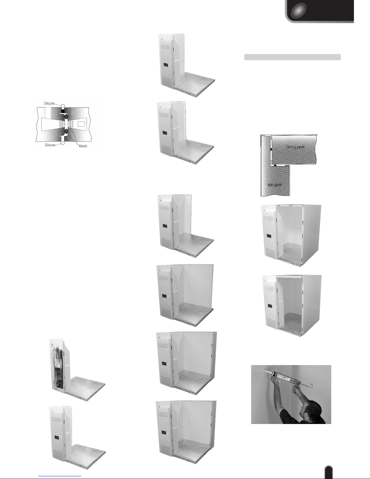
Figure 7
Figure 8
Figure 9
Figure 10
Figure 11
Figure 17
Figure 18
Figure 12
Figure 13
Figure 14
Figure 15
3
Wall/Corner Panels
Prior to positioning and locking the corner and wall
panels together:
Apply two beads of mastic as shown (see fig 7) to
the female extrusion only.
Position and lock adjacent wall / corner panels using
the same locking procedure as described in
‘Panel Locks’ (Step 4).
Lock the wall panel to the floor panel securing them
in to place.
NOTE: where access to external wall joints is not
possible after installation of coldroom, insert silicone
seal at the same time as mastic seals (see fig 7).
Do not silicone other joints at this time.
Refer to the Coldroom Assembly Detail for selection of the next wall panel and continue to erect
the rear wall, seal and lock into place until the
corner is reached (see fig12, 13 and 14).
With the sidewalls, rear and ceiling assembled
(see fig 18) seal all internal joints with silicone
sealer (see fig 19) taking care not to overfill.
Refer to the Coldroom Assembly Detail for selection of the next wall panel and continue to erect
the side wall, seal and lock into place but do not
fit the front corner (see fig15).
Ceiling Assembly
1. Apply two beads of mastic as shown (see fig
16) to the wall panel top recess.
2. Refer to the Coldroom Assembly Detail and
select a ceiling panel and place it in position.
3. Select the next ceiling panel seal the edge with
mastic and lock it to the first panel.
4. Continue until the whole ceiling is in position
(see fig 17 and 18) (on the smaller coldrooms
there will be two panels on larger coldrooms
more will be required).
STEP 7.
Figure 19
Figure 16
Front Left Hand Corner
Select the left-hand corner and adjacent wall panel
apply mastic to the edge of the female side of the
wall panel (see fig 7) and lock the corner to the panel.
Fit the white buttons into the corner/ wall lock holes
and apply a bead of silicon to the internal joint
between the wall and corner.
Apply mastic to the edge of the floor, female side of
the corner and the top of the 'L' shaped section also
(see fig 5 and 7).
Lift the corner/ wall panel and slot into place.
To lock the corner/ wall panel to the refrigeration
system panel it is necessary to open the door of the
refrigeration system panel (see fig 8). Remove the two
screws, one near the top of the door and one near
the bottom, from the opposite edge to the hinges
securing the door in the closed position. Remove the
white buttons from the holes adjacent to the lock
holes, Insert the hexagonal locking wrench into its
lock hole, making sure it is fully engaged, and lock
as described previously.
Fit the white buttons into the lock holes and refit the
white buttons in the holes in the door.
The mains lead for the coldroom is found behind the
refrigeration system door.
Pass the cable through the slot provided in the top of
the door ensuring that it does not get entangled in
any of the components.
Close the door and replace the screws ensuring they
are fully tightened.
With the refrigeration system panel and corner
locked firmly into place refer to the Coldroom
Assembly Detail for selection of the next wall
panel.
Select the next wall panel (see fig 9, 10 and 11),
and any subsequent side wall panel, seal and lock
into place until the rear corner is reached.
Page 4

english
GB
Figure 28
4
Figure 27
Detail shows positions of 2 of the
screw hole positions, the 3rd is
not shown
Door Jamb
Fitting
Select the door jamb without the door, apply
mastic to the edge of the floor, top of the 'L'
shaped section and the left hand side of the jamb
(see fig 5 and 7) as described previously, and fit
and lock into place (see fig 25).
STEP 10.
Threshold Plate
The threshold plate is the stainless steel portion of
the door jamb and requires fixing to the coldroom floor (see fig 27). With the jamb locked into
position, using the .42mm drill bit, drill three
holes in the coldroom floor through the predrilled holes in the threshold plate.
Using the zinc platted countersunk screws cut a
thread in the drilled holes, remove and discard.
Insert the flat headed stainless screws into the
threaded holes taking care not to over tighten.
STEP 12.
Door Fitting
Offer the door up to the door jamb, whilst holding it at a 90˚ angle to the jamb lower the door
so that both portions of the hinge assembly join
together. Once in position allow the door to
close. If the door does not close lift the door off
the hinges and check that the cam is located correctly on both portions of the hinge assembly. If
required make the necessary adjustments and refit the door.
The door should close with the handle coming
into contact with the strike and hold the door
firmly against the jamb creating a positive seal
with the gasket. If there is movement of the door
when in the closed position adjust the strike position using a pozi screwdriver.
STEP 13.
Sealing Joints
Seal all external joints with silicone sealer (see fig 28)
taking care not to overfill.
STEP 14.
Cleaning
The finished coldroom should be cleaned thoroughly
before loading.
STEP 15.
Figure 20
Capping Lock
Holes
Capping lock holes in walls and ceiling.
Insert the white plastic caps provided and tap in
using the shaft of a hammer ensuring they are
tight and flush fitting.
Capping lock holes Floors
To ensure an adequate fixing the lock hole plugs
for the floor are provided as a two part
component (see fig 20).
Insert the outer body into the hole and tap the
central pin in with a light hammer.
STEP 8.
Shelving
Assembly
A. Remove all packaging from the shelves
and posts..
B. Determine the position of the lowest shelf
(it is recommended that at least a 150mm
clearance from the floor is left to allow for
cleaning).
C. Snap on one half (see
fig 23) of the plastic collar onto the post (with
the thick end down).
Snap on the remaining
half of the collar and
slide up or down until
secured into the groove.
Repeat this for all four
posts.
D. Standing the shelf
poles upright, lower the shelf onto the poles
until the collars fit inside the corner of the
shelves (see fig 24).
E. With the shelf in position use a rubber
mallet to 'knock down' the shelf until it is
completely secured.
F. Repeat steps B, C, D
& E for the remaining
shelves.
G. The foot of each
pole can be adjusted to
compensate for uneven
surfaces.
NOTE: Assemble the first set of racking out
of the coldroom and place inside (see fig 21).
For rooms FPC 1.8 x 1.2, FPC 1.8 x 1.5 and FPC
1.8 x 1.8 the second and subsequent racks
will have to be assembled inside the room
(see fig 22).
For all of the remaining models the racking
can be assembled and placed inside when
assembled.
STEP 9.
Figure 23
Figure 21
Figure 25
Figure 26
Figure 22
Figure 24
Front Right
Hand Corner
Select the front right hand corner (see fig 26),
apply mastic to the edge of the floor, both sides
and the top of the ‘L’ shaped section of the corner
(see fig 5 and 7) as described previously, and lock
the corner into place.
STEP 11.
Before proceeding further assemble
the racking and position inside the
coldroom. Refer to the ‘Shelving
Arrangement’ on the separate sheet
for the shelving layout for your
particular coldroom.
Page 5

english
GB
5
When the controller is switched on a single line
appears on the display for 3 seconds to indicate the
autotest period.
After this period the air temperature measured by
the T1 probe is displayed.
LDU 15 Controller
Switching On
Important Note: If the refrigeration panel has
been laid down at any time it must be left in
the vertical position for at least one hour before
switching ON.
(For water cooled models proceed to step 18).
Plug the lead into a suitable socket and switch ON
the power to the unit.
Switch the unit on using the ON/OFF switch on the
control panel.
Do not load product into the coldroom until it has
achieved the correct working temperature.
Te mperature.
High Temperature coldroom +1˚C to +4˚C.
Low Temperature coldroom -18˚C to -21˚C.
STEP 16.
Water Cooled
Condensing System Connection Procedure
STEP 18.
Check temperature set point.
Check set point by pressing the ‘set’ button
To increase set point press ‘set’ +
To decrease set point press ‘set’ +
Factory Temperature Set Point +1˚C.
Exit from set up occurs after 10 seconds if
no button is pressed.
Alarms and Warnings
HI High Temperature Alarm
LO Low Temperature Alarm
E1 T1 Probe Failure
DF Defrosting in Progress
CLN Clean Condenser
Control Panel
STEP 17.
Te mperature
controller
Mains
ON/OFF
switch
Interior
light
switch
2
3
High Temperature Room Control Panel
When the unit is switched on the display shows “- - -”
for a period of five seconds, during which the
controller performs a self-check. The display then
shows the air temperature measured by probe 1.
Low Temperature Room Control Panel
set
"-#
"-#
"-#
"-#
aux
lae
aux
❆
3:2
CDC Controller
CDC 122
❆
❆
ALT
ALT
❆
❆
❆
5 6 7
1
4
❆
Check Set Point
Low point of temperature band.
Press and hold button 1 ( )
Increase Set Point
Press and hold button 1 ( ). Press button 3 ( )
until required temperature is displayed.
Decrease Set Point.
Press button. 1 ( ). Press button 4 ( ) until
required temperature is displayed.
Manual Defrost
Press and hold button 2 ( ). Press button 4 ( )
a timed defrost will follow.
Indicators
LED 5 Compressor on ( ).
LED 6 Evaporator Fan on ( ).
LED 7 Defrost on ( )
Alarms and Warnings
PF1 indicates air probe failure.
PF2 indicates evaporator probe failure.
Water cooled condensing kit.
Heat Exchanger complete with fan and cable.
2 x 30 metres flexible hoses.
4 x jubilee clips.
Tools required
Flat bladed screwdriver
Funnel
5 litre container for water
Step ladder
Determine the position of the Heat Exchanger (see
fig 29) before proceeding further with the installation.
Unit can be mounted up to 5 metres vertically away
from the compressor and up to 25 metres horizontally.
Weather proof housing to the remote system means it is
suitable for outdoor location.
It should be positioned in a cool area and out of
direct sunlight with no restriction to the airflow.
Either attach it to a wall by the fixing points, using
screws and wall plugs, or position on a flat roof
firmly securing it in place.
Once positioned connect the flexible water pipes to
the Water Inlet (A) and Water Outlet (B) connection,
securing them to the pipes using the jubilee clips
provided.
Run the flexible pipes to the refrigeration system
panel avoiding any sharp bends that could result in
kinks in the flexible pipes therefore impeding the
water flow.
Water Inlet ‘A’
Water Return ‘B’
Figure 29
Open the cover of the refrigeration system panel as
previously described.
Cut the pipes to the required length allowing sufficient surplus so that the pipes are not stretched.
Slide the jubilee clip over the end of the flexible
pipe. Connect the pipe connected to the top of the
condenser (Water Inlet 'A') to the 15mm copper
pipe (Water outlet 'A') at the left of the left-hand
side of the compartment. Slide the jubilee clip
over the connection and tighten securely to avoid
leakage.
Slide the jubilee clip over the end of the second
flexible pipe. Connect the pipe connected to the
bottom connection (Water return ‘B’) of the
heat exchanger to the 15mm pipe (Water Inlet ‘B’)
attached to the stainless steel tank. Slide the jubilee
clip over the connection and tighten securely to
avoid leakage.
Electrical Connection
Run the remote condenser fan cable to the
condensing unit with the water pipes.
Plug the male cable connector attached to the end
of the fan wire in to the female cable connector
attached to the wire next to the water fill pipe.
Leave any surplus cable on the top of the coldroom
Filling the system with water
Fill the 5-litre container with clean water.
Note: Anti-freeze
Where pipework to heat exchanger may be at risk
of freezing, add anti-freeze at 40% of total liquid
requirement.
Remove the plastic cap from the end of the
‘Water Fill Pipe’.
Insert the funnel in to the end of the Water Fill Pipe.
Slowly and with care, avoiding any spillage, poor 2
litres of the water into the tank.
Plug the mains lead in to the power source and turn
the unit ON.
After a short period the water pump will start to
circulate the water round the system.
Leave the pump to run for a further 2 minutes.
Switch the unit Off before adding the remaining 3
litres of water.
Switch the unit On and leave running for a few
minutes to check that the water is circulating
correctly.
Check the water level in of the tank by placing a
hand against the front, the tank if filled with
sufficient water will be warm half way up, if not it
may be necessary to add more water.
Refit the plastic cap to the water fill pipe.
On completion return to step 16.
Water Fill Pipe
Water Outlet ‘A’
Water Inlet ‘B’
remote
condenser fan
electrical
connection
Figure 30
Page 6

english
GB
6
Page 7

english
GB
7
Page 8

Foster Refrigerator
Oldmedow Road, King’s Lynn,
Norfolk, PE30 4JU
England
Tel: 01553 691122
Fax: 01553 691447
Website: www.fosterrefrigerator.co.uk
Email: sales@foster-uk.com
a Division of ITW (UK) Ltd.
OP/CONT/GB/4/05 00-599648
Installation Instructions
Packaged Coldroom
 Loading...