

Page 1

1
By Appointment to
Her Majesty Queen Elizabeth II
Suppliers of Commercial Refrigeration
Foster Refrigerator, King’s Lynn
Call: +44 (0)843 216 8800 Fax: +44 (0)843 216 4700 Email: support@foster-uk.com
www.fosterrefrigerator.co.uk
A Division of ITW Ltd
Foster Refrigerator,
Oldmedow Road,
King’s Lynn,
Norfolk, PE30 4JU
United Kingdom
ISO 9001 ISO 14001
Original Service Manual
EcoPro G2 Cabinets
FD1-11 Controller & Display
March 2012 Version 1
English
0771
Page 2
1
GB
1
Manual Information & Health & Safety Notes
1
Environmental Management Policy
2
Disposal Requirements & Electrical Safety
2
EcoPro G2 Cabinet Description
3
Display Icons & Switches
3
Start up, Standby, User Adjustments
4
Temperature Sensitivity, Key Security, Light Function, Downloading, Defrost Function &
Reduced Energy Control.
5
FD1-11 Controller Connection Drawing, Technical Data & Configuration of Parameters
6
Default Parameters Explained
7 to 12
Individual EcoPro G2 Cabinet Parameter Values
13 to 15
Technical Data
16 to 17
Wiring Diagrams & Probe details
18 to 20
Troubleshooting & Notes
21 to 24
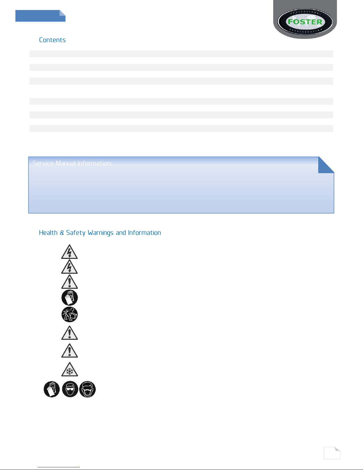
Make sure the power supply is turned off before making any electrical
repairs.
To minimise shock and fire hazards, please do not plug or unplug the unit
with wet hands.
During maintenance and cleaning, please unplug the unit where required.
Care must be taken when handling or working on the unit as sharp edges
may cause personal injury, we recommend the wearing of suitable PPE.
Ensure the correct moving and lifting procedures are used when relocating a
unit.
Do NOT use abrasive cleaning products, only those that are recommended.
Never scour any parts of the refrigerator. Scouring pads or chemicals may
cause damage by scratching or dulling polished surface finishes.
Failure to keep the condenser clean may cause premature failure of the
motor/compressor which will NOT be covered under warranty policy.
Do NOT touch the cold surfaces in the freezer compartment. Particularly
when hands are damp or wet, skin may adhere to these extremely cold
surfaces and cause frostbite.
Please ensure the appropriate use of safety aids or Personnel Protective
Equipment (PPE) are used for you own safety.
The products and all information in this manual are subject to change without prior notice.
We assume by the information given that the person(s) working on these refrigeration units are
fully trained and skilled in all aspects of their workings. Also that they will use the appropriate safety
equipment and take or meet precautions where required.
The service manual does not cover information on every variation of this unit; neither does it cover the
installation or every possible operating or maintenance instruction for the units.
Page 3
2
GB
2
Product Support and Installation Contractors.
Foster Refrigerator recognises that its activities, products and services can have an adverse impact
upon the environment.
The organisation is committed to implementing systems and controls to manage, reduce and
eliminate its adverse environmental impacts wherever possible, and has formulated an
Environmental Policy outlining our core aims. A copy of the Environmental Policy is available to all
contractors and suppliers upon request.
The organisation is committed to working with suppliers and contractors where their activities have
the potential to impact upon the environment. To achieve the aims stated in the Environmental
Policy we require that all suppliers and contractors operate in compliance with the law and are
committed to best practice in environmental management.
Product Support and Installation contractors are required to:
1. Ensure that wherever possible waste is removed from the client’s site, where arrangements are in
place all waste should be returned to Foster Refrigerator’s premises. In certain circumstances waste
may be disposed of on the client’s site; if permission is given, if the client has arrangements in place
for the type of waste.
2. If arranging for the disposal of your waste, handle, store and dispose of it in such a way as to
prevent its escape into the environment, harm to human health, and to ensure the compliance with
the environmental law. Guidance is available from the Environment Agency on how to comply with
the waste management ‘duty of care’.
3. The following waste must be stored of separately from other wastes, as they are hazardous to the
environment: refrigerants, polyurethane foam, and oils.
4. When arranging for disposal of waste, ensure a waste transfer note or consignment note is
completed as appropriate. Ensure that all waste is correctly described on the waste note and include
the appropriate six-digit code from the European Waste Catalogue. Your waste contractor or Foster
can provide further information if necessary.
5. Ensure that all waste is removed by a registered waste carrier, a carrier in possession of a waste
management licence, or a carrier holding an appropriate exemption. Ensure the person receiving the
waste at its ultimate destination is in receipt of a waste management licence or valid exemption.
6. Handle and store refrigerants in such a way as to prevent their emission to atmosphere, and
ensure they are disposed of safely and in accordance with environmental law.
7. Make arrangements to ensure all staff who handle refrigerants do so at a level of competence
consistent with the City Guilds 2078 Handling Refrigerants qualification or equivalent qualification.
8. Ensure all liquid substances are securely stored to prevent leaks and spill, and are not disposed of into storm
drains, foul drain, or surface water to soil.
If not disposed of properly all refrigerators have components that can be harmful to the
environment.
All old refrigerators must be disposed of by appropriately registered and licensed waste contractors, and
in accordance with national laws and regulations.
Foster Refrigerator recommends that the equipment is electrically connected via a Residual Current
Device; such as a Residual Current Circuit Breaker (RCCB) type socket, or through a Residual Current
Circuit Breaker with Overload Protection (RCBO) supplied circuit.
Page 4
3
GB
3
The EcoPro G2 range comes as a Full Gastronorm format in a variety of capacities and
temperatures. A standard unit comes with 2/1 shelves (3 with a single model, 6 with a double
model).
The fish model comes fitted with fixed racking to take 7 fish boxes (198kgs) as standard whereas
the wine version comes with a racking assembly that holds either 140x75cl bottles (for a single
model) or 280 x 75cl (for a double model).
The units are manufactured as a one piece shell with easy clean stainless steel exterior. Each
conforms to the current legislation and exceeds the Montreal protocol by using zero ODP (ozone
depleting substances) refrigerants and insulation. There is also the added option of having
Hydrocarbon refrigerant with certain model variations.
Each unit’s temperature is controlled by a microprocessor with digital temperature display. There are
several temperature options available exceeding the Climate Class 5 operations by giving an
ambient temperature to 43°C.
Each temperature display is also easy to read with a wipe clean finish.
The standard form of refrigeration system in this unit is integrated with an air-cooled condensing
unit that allows cooled air to circulate through the evaporator, via the fan into storage areas. It does
this by distributing the refrigerant into the evaporator controlled by a capillary.
Remote systems are also available as an option, the difference being, the evaporator is controlled by
an expansion valve instead of capillary.
Other points to be made on these units are that they have coated coils to prevent corrosion and to
help prolong the refrigerator’s life.
Cabinets come with an easily removable plug box and lid.
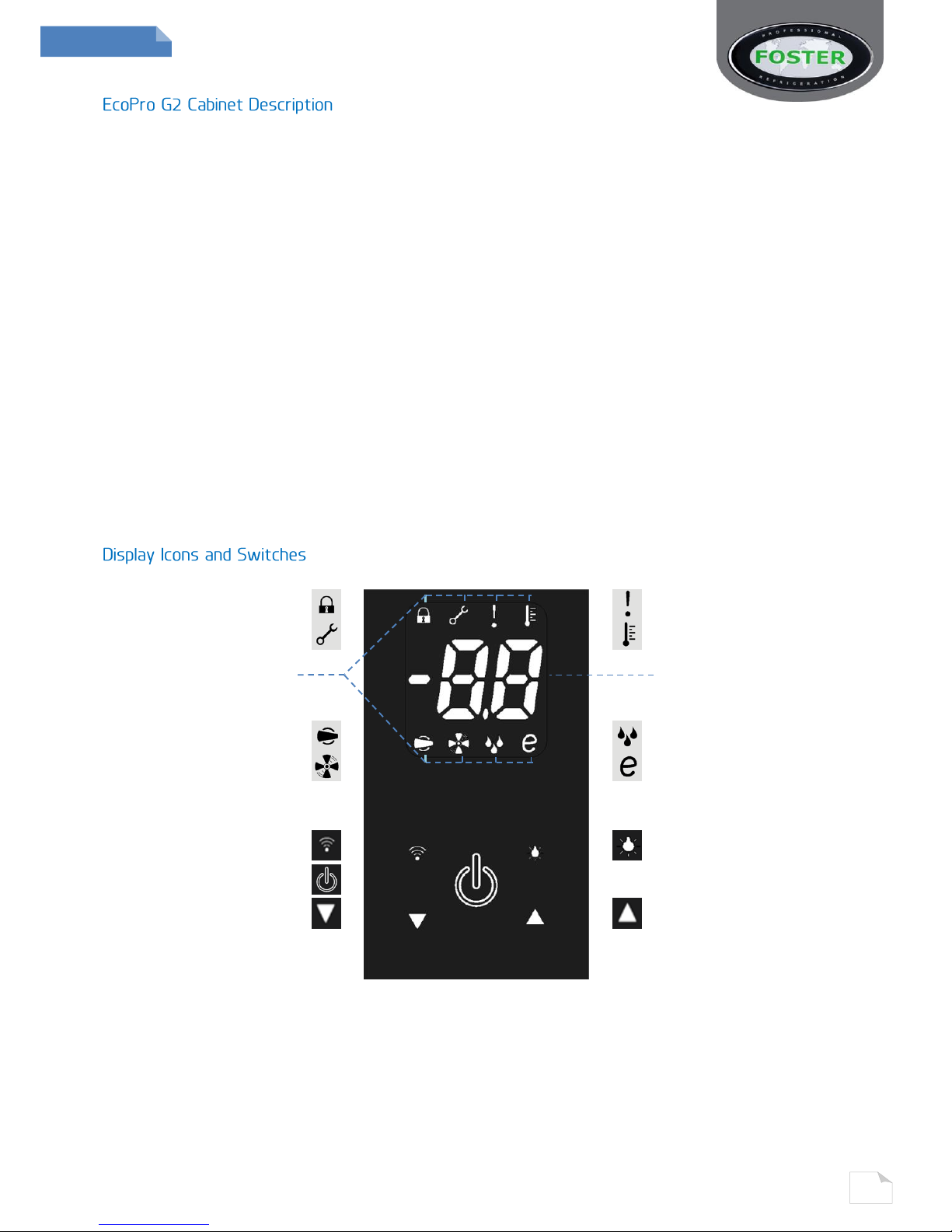
Keypad Lock
Warning/ Alarm
Service Mode
Temperature Setting
Functions Icons
Temperature Display
Compressor Function
Defrost Function
Evaporator Fan Function
Reduced Energy Mode
Data Download Switch
Light Switch
Power Switch
Decrease Switch
Increase Switch
(Some icons or switches are only visible during adjustment, when activated by parameters or
through operation/manual selection).
Page 5
4
GB
4
Initial Set Up
After unpacking clean and allow the cabinet to stand for 2 hours before turning on.
Ensure the cabinet is situated where neither hot nor cold air sources will affect its performance.
Make sure that a minimum clearance of 310mm above and 50mm around the cabinet is available for
ventilation and effective operation.
Initial Start up
Connect the unit to a suitable mains power outlet and turn the supply on. Please do not plug or
unplug the unit with wet hands.
The cabinet will energise briefly showing -- followed by the power switch slowly pulsing with a
blank display. The unit is now in standby.
Pressing this switch for 3 seconds will turn the unit on (the switch backlight is static and the display
shows the operating temperature) or put into standby (the switch backlight pulses slowly on & off).
As the operating temperature has been pre-set no adjustments are required. Allow the cabinet to
reach its normal/set operating temperature before loading.
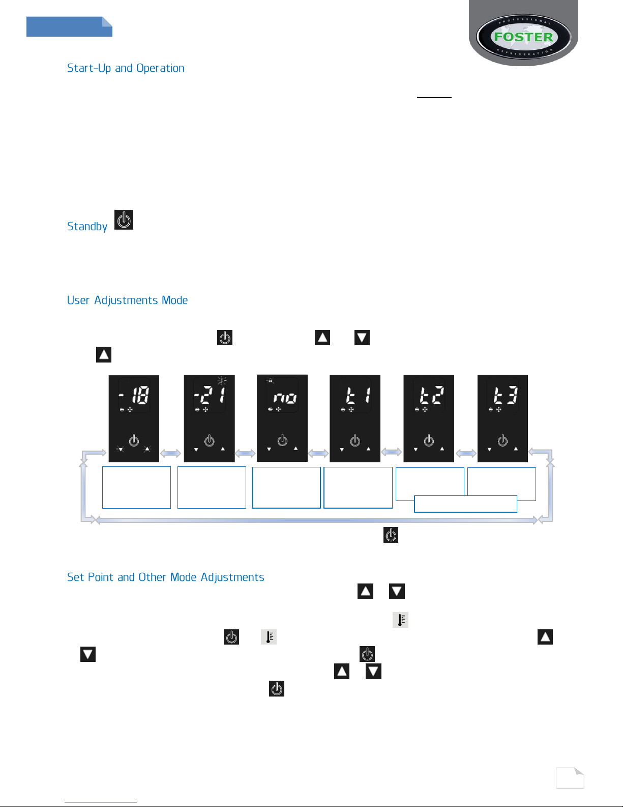
You are required to enter this mode to make any setup changes.
These include Set Point, Keypad Security, and display of T1, 2 or 3 probe temperatures.
Press and immediately release , after which the and switches will flash/pulse together.
Press to scroll through the following screens:
To exit this mode scroll back to the adjustment screen and press or wait for 30 seconds and the
display will revert to the normal display showing the operating temperature.
Access the adjustment mode as described above. Using the or switches to scroll to the mode
that requires adjustment i.e. ‘Set Point’ this is the minimum temperature the cabinet is allowed to
cool down to (the display shows the temperature and flash/pulsing icon).
To adjust this press and release the icon will show constantly. Adjust the setting with the
or switch. Confirm the change by pressing and releasing again, the next mode will
automatically show. Scroll through the modes with the or switch until you return to the
adjustment screen and press and release to exit and save.
If at any point the display is left for 30 seconds it will revert to the normal display and no
changes will be saved.
T1
Probe
Temperature
Keypad
Security
Screen
Set
Point
Screen
Adjustment
Screen
T2 Probe
Temperature
T3 Probe
Temperature
Only visible when fitted
Page 6
5
GB
5
If you require the cabinet to have a more accurate or increased sensitivity to temperature and the
warnings this controls, the controller is able to measure temperature in 1/10ths of a degree (0.1°)
instead of whole degrees.
With parameter ‘SC’ set to ‘1C’ the display will show the temperature as 1/10ths of a degree on the
scale between -9.9°C to +9.9°C.
Also, with parameter ‘SC’ set to ‘1F’ the controller has the facility to show the temperature in Fahrenheit (between 58°F to 99°F). However if this is selected all other temperature related parameter values will have to be set
accordingly to this change. (See ‘Configuration of Parameters’ for information on how to access this).
Access the ‘Keypad Security’ screen as described before.
The screen will show the current status, initially pre-set to ‘ ’, with flashing. Press and release
and will show constantly. (If you modify this setting with to show ‘ ’ the keypad will be
locked, will show constantly and the cabinet will not be able to be put into standby, carry out a
manual defrost, adjust temperature set point, download data or switch on/off the units lights. To
confirm any change you must press again so the next screen ‘ ’ shows).
Exit any of the ‘Adjustment Modes’ as described before.
To switch on the lights press and release so that the switch backlight is on continuously. To
switch off press and release and the switch backlight will flash/pulse.
This option is only available when enabled via parameters and the cabinet has the additional FCOM1
device available –this availability will be shown by the data switch being constantly illuminated.
To download the data the switch should be pressed and then released. The information will then begin
downloading to the appropriate printer or PC and the backlight of the switch will flash. On completion the switch will
return to constant state of illumination.
All Foster G2 cabinets are fitted with a fully automatic defrost system to ensure that the evaporator
coil remains free from ice during normal use. Melt-water is evaporated using either the heat from
the refrigeration system or a separate electric heater (dependent upon model and configuration).
To activate a manual defrost – while the cabinet is in ‘run’ mode press and hold for 5
seconds. After 3 seconds the display will go blank then return after a further 2 seconds. At this point
a defrost will be performed (subject to underlying operating parameters), this will terminate
automatically.
The reduced energy control mode (‘e’ mode) detects when the unit has reached the selected
temperature set-point and the operating conditions (such as usage rate) have become less
demanding.
When enabled, the controller will modify the compressor, evaporator fan and defrost operation in
order to reduce the energy consumed. During the reduced energy control mode is illuminated at
the bottom right corner of the display.
Upon an increase in operating demand the controller reverts back to the standard operating settings
with the symbol extinguished. The ‘e’ mode is enabled by setting parameter ‘iiM’ to ‘Au’. Further
parameter settings (‘iiS’, ‘iit’, ‘iiP’, ‘iiY’, ‘iiF’, ‘iid’, and ‘iiE’) control the temperature cycle during the
reduced energy control mode. Setting parameter ‘iiM’ to ‘no’ disables the ‘e’ mode.
Page 7
6
GB
6
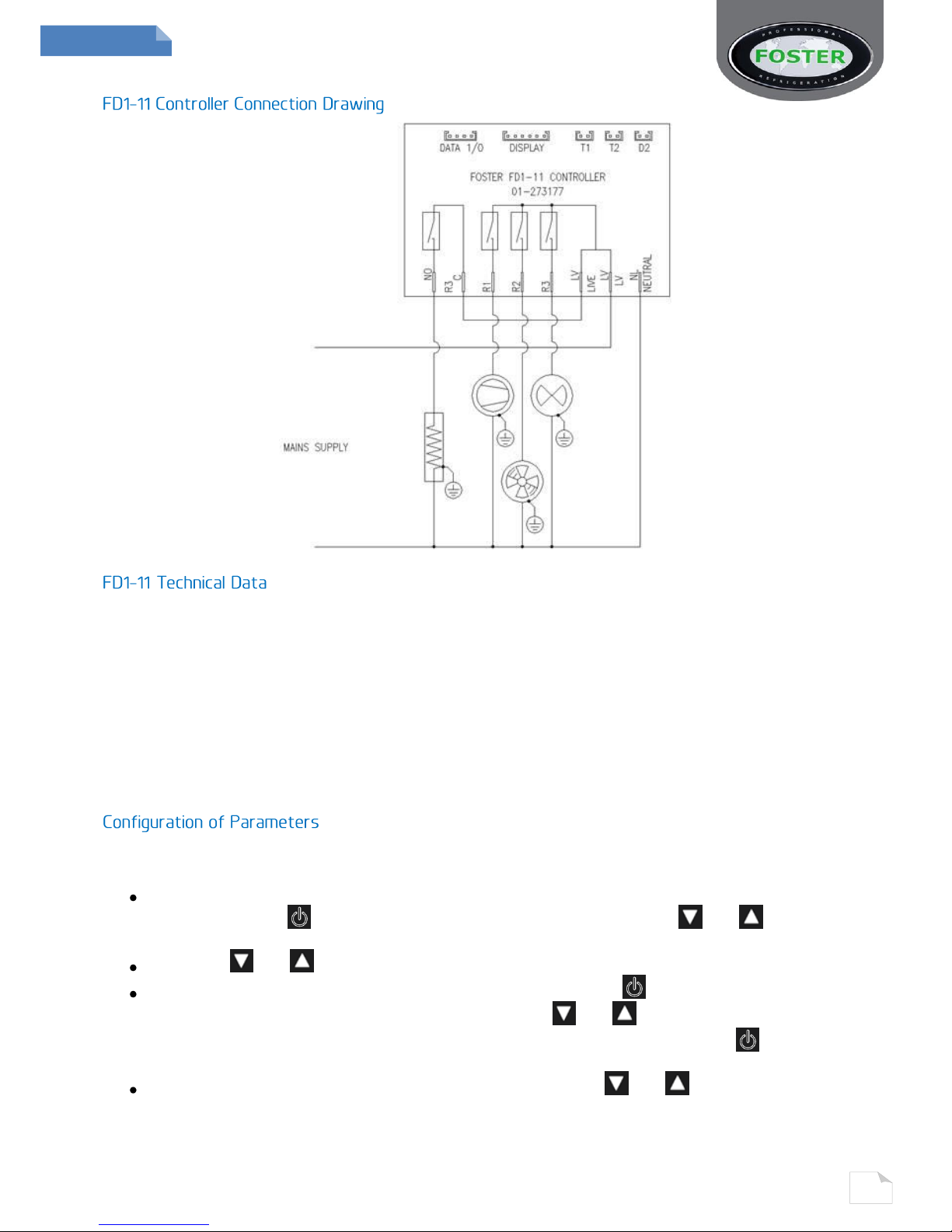
Power Supply
FD1-11
230Vac±10%,
50/60Hz, Operating 3.2W, Standby 0.9W
Measurement Range
-50…120°C, -55…240°F
-50 / -9.9…19.9 / 80°C (NTC 10K Only)
Relay Output
Compressor - 16(8) A 240Vac
Defrost - 16(4) A 240Vac
Measurement Accuracy
<0.5°C within the measurement range
Evap. Fan - 16(4) A 240Vac
Auxiliary Loads 1 - 8(2) A 240Vac
Input
NTC 10KΩ@25°C
CE (Reference norms)
EN60730-1; EN60730-2-9
EN55022 (Class B)
EN50082-1
Parameters should not be changed unless you have an understanding of their purpose and
the following instructions are fully understood.
To gain access to the parameters use the ‘Adjustment Mode’. This is accessed by pressing
and releasing the switch. After selecting this mode press and hold and together
for 5 seconds. The first parameter will show on the display.
Using the and switches you can scroll through all parameters and their values.
If you wish to change a parameter value press and release the switch when one the
desired mnemonic. Once selected in this way use the and switches to modify. When
the new reuired value is shown it will be saved by pressing and relaeasing the switch.
After which the display will show the next parameter.
To exit this mode or revert to normal operating mode, press and together then
release.
If at any point no buttons are pressed for 30 seconds without saving a new value the display will
return to the standard temperature display without changes being made.
Page 8
GB
EcoPro G2 FD1-11 Controller Default Parameter Values
Para Cond Range Description Dim FD1-11
SL -50 ... SH Minimum limit for ‘SP’ setting °C 1
SH SL … 90° Maximum limit for ‘SP’ setting °C 3
SP SL ... SH Temperature set point to be achieved °C 1.5
CH RF - HE Refrigeration or Heating control mode Flag RF
HY 1 … 9.9° Off/On thermostat differential °K 3
CR 0 ... 30min Compressor Rest Time Min 2
C1 0 ... 30min
Thermostat run times with faulty T1
probe (‘C’ = 0 output with faulty T1 will
always be off).
Min 6
C2 0 ... 30min
Thermostat run times with faulty T1
probe (‘C1’ = ‘0’ & ‘C1’ => ‘0’ output with
faulty T1 will always be on
Min 4
CS 0 ... 30min
Compressor stop delay after door has
been opened (only if ‘DS’ – ‘1’)
Min 1
DM
Defrost start mode:
Func. TM
NO
Defrost is disabled (the following
parameter will be ‘FM’)
TM Regular time defrost
FR
Defrost time elapses only in condition of
frost accumulation
DB
‘DM’ = ‘TM’ or ‘FR’
0 ... 90 Hrs Time interval between defrosts Hrs 6
DF
Defrost tmer clock:
Flag YS
YS
Following mains interruption, timer
resumes count
NO
Following mains interruption, timer
restarts from zero
DL -50 … 90°
Defrost end temperature (only if ‘T2’ =
‘1’)
°C 15
DT 1 ... -0min Maximum defrost duration Min 20
DY
Defrost type:
Func. OF
OF
Timed off cycle defrost (compressor and
heater off)
EL
Electric heater defrost (compressor and
heater on).
GS
Hot gas defrost (compressor and heater
on)
DS
Defrost synchronisation:
Func. HI
OF
No synchronisation (defrost occurs
immediately when scheduled).
LO
Defrost waits until T1 = lowest part of
cycle (when compressor would normally
‘cut-off’).
HI
Defrost waits until T1 = highest part of
cycle (when compressor would normally
‘cut-in’).
ST 0 ... 30min
Defrost synchronisation time out when
‘DS’ = ‘LO’ to provide maximum time
defrost can be deferred.
Min 5
DP 0 ... 90sec
Evaporator pump down. Timed pause at
start of defrost
Sec 0
DR 0 ... 20sec
Defrost pressure reduction. At end of defrsot, time compressor continues running
after hot gas solenoid valve shuts
Sec 3
DN 0 ... 30min Drain down period Min 1
Page 9

8
GB
8
DD
‘DM’ = ‘TM’ or ‘FR’
Defrost display mode:
Func.
SP
RT
Real (actual) air temperature
LT
Last temperature display before start of
defrost
SP
The current set point value
DF
Display will show ‘dp’.
DH
0 … 60min
Defrost display delay period. Time ‘DD’
is shown following defrost termination.
Min
3
FD
Fans in defrost:
Flag
YS
YS
Fans run during defrost
NO
Fans do not run during defrost
FR
-50 … 90°
Evaporator fan restart temperature
following defrost. (Only if ‘T2’ = ‘1’).
°C
5
FS
0 … 90min
Maximum evaporator fan stop period
defrost (only when ‘T1’ = ‘1’).
Min
3
FM
Evaporator fan mode during
thermostatic control:
Func.
TM
NO
Fan(s) run continuously (subject to door
& defrost).
TP
Temperature based control. When
compressor is on, fans are on.
TM
When compressor is off, fans run as long
as temperature difference Te-Ta > ‘FT’.
Fans on again with ‘FH’.
FT
-9.9 … 0°
Te-Ta difference for fans to turn off after
compressor stopped. (Only if ‘T2’ – ‘YS’
and ‘FM’ = ‘TM’)
°K
-1
FH
1 … 9.9°
Temperature differential for evaporator
fan restart (Only if ‘T2’ – ‘YS’ and ‘FM’ =
‘TM’)
°K
3
F1
0 … 90sec
Evaporator fan stop delay after
compressor stop
Sec
10
F2
0 … 90sec
Timed fan stop following ‘F1’ (With F2 =
‘0’ the fans remain on all the time).
Sec
30
F3
0 … 90sec
Timed fan stop following ‘F2’ (With F3 =
‘0’ & F2 > 0 the fans remain off all the
time).
Sec
20
FP
0 … 90sec
Minimum evaporator fan stop period
(following door opening etc.).
Sec
20
AT
Alarm threshold configuration:
Func.
RL
NO
All temperature alarms are inhibited
(the following parameter will be ‘AO’).
AB
The value set in ‘AL’ & ‘AH’ represent
actual alarm set points
RL
The values set in ‘AL’ & ‘AH’ are alarm
differentials which relate to ‘SP’ and ‘SP’
+ ‘HY’ (the following parameter will be
‘LD’)
AL
‘AM’
=
‘AB’
-50 … 90°
Low temperature alarm threshold
°C
-3
AH
-50 … 90°
High temperature alarm threshold *the
following parameter will be ‘AI’).
°C
8
LD
‘AM’ = ‘RL’
-9.9 … 0°
Low temperature differential (With ‘LD’
= ‘0’ the low temperature alarm is
excluded)
°K
-5
HD
0 … 9.9°
High temperature differential (With ‘HD’
= ‘0’ the low temperature alarm is
excluded).
°K
5
Page 10

9
GB
9
AI
‘AM’ = ‘AB’ or
‘RL’
Alarm Probe:
Func.
T1
T1
Air temperature probe used for alarm
detection
T2
Evaporator temperature probe used for
alarm detection (if ‘T2’ = ‘YS’).
T3
Third temperature probe used for alarm
detection (if ‘D2’ = ‘T3’).
AD
0 … 90min
Delay before alarm temperature warning
Min
90
AO
0 … 30min
Delay before door open alarm warning
(only when ‘D1’ or ‘D2’ = ‘DS’)
Min
5
PF
0 … 30°
Power failure alarm differential. (With
‘PF’ = ‘0’ power failure alarm is
disabled).
°K
10
AM
Operation in case of high condenser
alarm (if ‘D2’=‘T3’ and ‘T3’=‘CD’):
Func.
NO
NO
High condenser temperature alarm
inhibited
AP
Condenser warning – ‘HC’ displayed,
alarm sounds, operation continues.
ST
As ‘AP’ above, but compressor stopped
(R1 de-energised) and defrosts
suspended.
AS
-50 … 90°
Condenser alarm temperature (if ‘D2’ =
‘T3’).
°C
65
AF
Operation in case of high pressure
alarm (if ‘D2’ = ‘HP’):
Func.
ST
AP
Pressure warning – ‘HP’ displayed, alarm
sounds, operation continues.
ST
As ‘AP’ above, but compressor stopped
(R1 de-energised) and defrosts
suspended.
SA
All relays de-energised while condition
exists.
AC
0 … 52 wks.
Condenser cleaning period. (With ‘AC’ =
‘0’ condenser cleaning alarm is disabled)
Wks.
0
IIM
Switchover method to reduced
energy mode:
Func.
AU
NO
Reduced energy model is excluded (the
following parameter will be ‘DC’).
AU
Reduced energy mode is activated/ deactive automatically via ‘IIS’ and ‘IIT’
D2
Second parameter set activated by ‘D2’
input (‘D2’ = ‘IIM’)
IIS
IIM = ‘AU’ or ‘D2’
1 … 90min
Minimum ‘non activity’ time for reduced
energy mode
Min
20
IIT
1 … 10°
Maximum temperature ‘addition’ for
reduced energy mode
°C
6
IIP
1 … 50°
Reduced energy mode temperature set
point – differential above ‘SP’
(refrigerating) below ‘SP’ (heating).
°K
2
IIY
1 … 10°
Reduced energy mode ‘off/on’
thermostat differential.
°K
3
Page 11

10
GB
10
IIF
IIM = ‘AU’ or ‘D2’
Evaporator fan control during
‘Reduced Energy’ operation:
Func.
TM
NO
Fan(s) run continuously
TP
Temperature based control. When
compressor is on, fans are on. When
compressor is off, fans run as long as
temperature difference Te-Ta > ‘FT’.
Fans on again with ‘FH’.
TM
Time based control. When compressor is
on, fans are on. When compressor is off,
fans in accordance to parameters ‘F1’,
‘F2’ and ‘F3’.
IID
0 … 90 Hrs
Time interval between defrosts in
reduced energy mode.
Hrs.
12
IIE
Display during reduced energy
mode
Func.
LT
RT
Real (actual) air temperature
LT
Last temperature display before reduced
energy mode.
IIP
The calculated set point value (‘SP’ +
‘IIP’)
DC
Data collection and download
function (FCOM fitted):
Flag
NO
YS
Data collection/download function
enabled via switch (L3 illuminated)
NO
Data collection/download function
disabled.
SB
Standby Button operation:
Flag
YS
YS
Standby button enabled
NO
Standby button disabled
DO
Configurable digital input operation:
Func.
DS
NO
Digital input not activated
DS
Door switch input
AO
Alarm (‘AL’ displayed) when contact
opens.
AC
Alarm (‘AL’ displayed) when contact
closes.
D1
Configurable digital input operation:
Func.
NO
NO
Digital input not activated
DS
Door switch input
AO
Alarm (‘AL’ displayed) when contact
opens.
AC
Alarm (‘AL’ displayed) when contact
closes.
D2
Configurable digital input operation:
Func.
NO
NO
Digital input not activated
DS
Door switch input
AO
Alarm (‘AL’ displayed) when contact
opens.
AC
Alarm (‘AL’ displayed) when contact
closes.
HP
High pressure switch input (normally
closed/ alarm when open).
IIM
Operates reduced energy mode when
contact closes.
T3
Allows for 3rd temperature probe
function.
Page 12

11
GB
11
T3
‘D2’ = ‘T3’
T3 probe function (only when ‘D2’ =
‘T3’):
Flag
DP
DP
T3 probe temperature displayed
CD
Condenser temperature measurement
O3
-9.9 … 9.9°C
T3 probe temperature offset (only when
‘D2’ = ‘T3’):
°K
0
LM
Light control mode (if ‘R3’ = ‘LM’):
Func.
NO
NO
Light control mode disabled (always off)
MN
Light output operation is
activated/deactivate by switch (L5
illuminated).
0O
Light output is switched on when door is
opened (if ‘D1’ = ‘DS’).
1O
Light output is switched on when door is
closed (if ‘D1’ = ‘DS’).
2O
Light output is switched on when door is
opened (if ‘D2’ = ‘DS’).
2C
Light output is switched on when door is
closed (if ‘D2’ = ‘DS’).
R2
Relay 2 operation:
Func.
EF
NO
Output disabled (always off).
EF
Control of evaporator fan.
DF
Control of defrost heater/device
(activated when ‘DY’ = ‘EL’ or ‘GS’),
LM
Output enabled for light control.
01
Contacts open/close with ‘Standby’/’on’
mode (‘SB’ = ‘1’)
AO
Contacts open when an alarm condition
occurs
AC
Contacts close when an alarm condition
occurs
(Relay contacts open when in standby
mode).
R3
Relay 3 operation:
Func.
NO
NO
Output disabled (always off).
EF
Control of evaporator fan.
DF
Control of defrost heater/device
(activated when ‘DY’ = ‘EL’ or ‘GS’),
LM
Output enabled for light control.
01
Contacts open/close with ‘Standby’/’on’
mode (‘SB’ = ‘1’)
AO
Contacts open when an alarm condition
occurs
AC
Contacts close when an alarm condition
occurs
(Relay contacts open when in standby
mode).
Page 13

12
GB
12
R4
Relay 4 operation:
Func.
NO
NO
Output disabled (always off).
EF
Control of evaporator fan.
DF
Control of defrost heater/device
(activated when ‘DY’ = ‘EL’ or ‘GS’),
LM
Output enabled for light control.
01
Contacts open/close with ‘Standby’/’on’
mode (‘SB’ = ‘1’)
AO
Contacts open when an alarm condition
occurs
AC
Contacts close when an alarm condition
occurs
(Relay contacts open when in standby
mode).
O1
-9.9 … 9.9°C
Air temperature probe (T1) offset
°K
0
T2
T2 probe enabling:
Flag
0
YS
T2 probe enabled
NO
T2 probe disabled
O2
-9.9 … 9.9°C
Evaporator temperature probe (T2)
offset
°K
0
SC
Readout scale:
Func.
2C
1C
Range -50 … 99°C (0.1°C resolution
within -9.9 to +9.9°C)
2C
Range -50 … 99°C
1F
Range -58 … 99°F
SM
0 … 99
Display slowdown
Func.
5
AR
1 … 64
FD1-11 address for PC communication
Flag
1
Page 14

13
GB
FD1-11 Default
EP700F
EP700G
EP1440G & EP700PG
EP700GR
EP1440GR
EP700HH (H Bottom
section)
EP700H & HL (H), G700H
EP700HB
EP700HL (H) (McDonalds
Germany Top Section)
EP1440H, 700P, G1440H
EP700HR, EP820HUR
EP1440HR
EP700HU, EP820HU
EP700HL (L)
EP700L, G700L
EP700L (Spirit Spec.)
EP700LB
EP700LL (L) Top Section
EP1440L, G1440L
EP700LR, EP820LUR
EP1440LR
EP700LU, EP820LU
EP700LU (Weatherspoon
Spec)
EP700M, G700M
EP1440M, G1440M
EP700MR
EP1440MR
EP700MU
EP820MU (Waitrose Spec)
EP700W
EP1440W
EP1440HU
EP1440LU
EP1440MU
Version
1 2 3 4 5 6 7 8 9
10
12
13
14
16
17
18
19
20
21
23
24
25
26
28
29
31
32
33
34
35
36
37
38
39
Par
SL
1
1 1 1 1 1 1 1 0 1 1 1 1 1
-21
-21
-21
-30
-21
-21
-21
-21
-21
-21
-2
-2
-2
-2
-2
-2
8 8 1
-21
-2
SH
3
1 3 3 3 3 3 3
10
3 3 3 3 3
-19
-19
-21
5
-19
-19
-19
-19
-19
-19
8 8 8 8 8
8
12
12
3
-19
8
SP
1.5
-1
1.5
1.5
1.5
1.5
1.5
1.5
2
1
1.5
1.5
1.5
1.5
-21
-21
-21
-18
-21
-21
-21
-21
-21
-21
-1.5
-1.5
-1.5
-1.5
-1.5
-1.5
10
10
1.5
-21
-1.5
CH
RF
RF
RF
RF
RF
RF
RF
RF
RF
RF
RF
RF
RF
RF
RF
RF
RF
RF
RF
RF
RF
RF
RF
RF
RF
RF
RF
RF
RF
RF
RF
RF
RF
RF
RF
HY
3
2 3 3 3 3 3 3 3 3 3 3 3 3 3 3 3 3 3 3 3 3 3 3 3 3 3 3 3 3 3 3 3 3
3
CR
2
2 2 2 0 0 2 2 2 4 2 0 0 2 2 2 5 2 2 2 0 0 2 2 2 2 0 0 2 2 2 2 2 2
2
C1
6
6 6 6 6 6 6 6 6 6 6 6 6 6 6 6 6 6 6 6 6 6 6 6 6 6 6 6 6 6 6 6 6 6
6
C2
4
4 4 4 4 4 4 4 4 4 4 4 4 4 4 4 4 4 4 4 4 4 4 4 4 4 4 4 4 4 4 4 4 4
4
CS
1
1 1 1 1 1 1 1 1 1 1 1 1 1 1 1 1 1 1 1 1 1 1 1 1 1 1 1 1 1 1 1 1 1
1
DM
TM
NO
TM
TM
TM
TM
TM
TM
TM
TM
TM
TM
TM
TM
TM
TM
TM
TM
TM
TM
TM
TM
TM
TM
TM
TM
TM
TM
TM
TM
TM
TM
TM
TM
TM
DB
6
6 6 6 6 6 6 6 8 6 6 6 6 6 6 6 6 8 6 6 6 6 6 6 6 6 6 6 6 6 6 6 6 6
6
DF
YS
YS
YS
YS
YS
YS
YS
YS
YS
YS
YS
YS
YS
YS
YS
YS
YS
YS
YS
YS
YS
YS
YS
YS
YS
YS
YS
YS
YS
YS
YS
YS
YS
YS
YS
DL
15
15
15
15
15
15
15
15
15
15
15
15
15
15
15
15
15
15
15
15
15
15
15
15
15
15
15
15
15
15
15
15
15
15
15
DT
20
20
20
20
20
20
20
20
20
20
20
20
20
20
20
20
20
20
20
20
20
20
20
20
20
20
20
20
20
20
20
20
20
20
20
DY
OF
OF
OF
OF
OF
OF
OF
OF
OF
GS
OF
OF
OF
OF
EL
GS
GS
GS
EL
GS
EL
EL
EL
EL
GS
GS
EL
EL
EL
GS
OF
OF
OF
EL
EL
DS
HI
HI
HI
HI
HI
HI
HI
HI
HI
HI
HI
HI
HI
HI
HI
HI
HI
HI
HI
HI
HI
HI
HI
HI
HI
HI
HI
HI
HI
HI
HI
HI
HI
HI
HI
ST
5
5 5 5 5 5 5 5 5 5 5 5 5 5 5 5 5 5 5 5 5 5 5 5 5 5 5 5 5 5 5 5 5 5
5
DP
0
0 0 0 0 0 0 0 0 0 0 0 0 0 0 0 0 0 0 0 0 0 0 0 0 0 0 0 0 0 0 0 0 0
0
DN
1
1 1 1 1 1 1 1 1 1 1 1 1 1 1 1 1 5 1 1 1 1 1 1 1 1 1 1 1 1 1 1 1 1
1
DD
SP
SP
SP
SP
SP
SP
SP
SP
SP
SP
SP
SP
SP
SP
SP
SP
SP
SP
SP
SP
SP
SP
SP
SP
SP
SP
SP
SP
SP
SP
SP
SP
SP
SP
SP
DH
3
3 3 3 3 3 3 3 3 3 3 3 3 3 6 6
6
10
6 6 6
6 6 6 3 3 3 3 3 3 3 3 3 6
3
FD
YS
YS
YS
YS
YS
YS
YS
YS
YS
NO
YS
YS
YS
YS
NO
NO
NO
NO
NO
NO
NO
NO
NO
NO
NO
NO
NO
NO
NO
NO
YS
YS
YS
NO
NO
FR
5
5 5 5 5 5 5 5
10
5 5 5 5 5
-5
-5
10
-5
-5
-5
-5
-5
-5
-5
5 5 5 5 5 5 5 5 5
-5
5
FS
3
3 3 3 3 3 3 3 3 3 3 3 3 3 3 3 3 3 3 3 3 3 3 3 3 3 3 3 3 3 3 3 3 3
3
FM
TM
TM
TM
TM
TM
TM
TM
TM
NO
TM
TM
TM
TM
TM
TM
TM
TM
NO
TM
TM
TM
TM
TM
TM
TM
TM
TM
TM
TM
TM
TM
TM
TM
TM
TM
Page 15

14
GB
Version
1
2 3 4 5 6 7 8
9
10
12
13
14
16
17
18
19
20
21
23
24
25
26
28
29
31
32
33
34
35
36
37
38
39
FT
-1
-1
-1
-1
-1
-1
-1
-1
-1
-1
-1
-1
-1
-1
-1
-1
-1
-1
-1
-1
-1
-1
-1
-1
-1
-1
-1
-1
-1
-1
-1
-1
-1
-1
-1
FH
3
3
3 3 3 3 3 3 3 3 3 3 3 3 3 3 3 3 3 3 3 3 3 3 3 3 3 3 3 3 3 3 3 3 3
F1
10
10
10
10
10
10
10
10
10
10
10
10
10
10
10
10
10
10
10
10
10
10
10
10
10
10
10
10
10
10
10
10
10
10
10
F2
30
30
30
30
30
30
30
30
30
30
30
30
30
30
30
30
30
30
30
30
30
30
30
30
30
30
30
30
30
30
30
30
30
30
30
F3
20
20
20
20
20
20
20
20
20
20
20
20
20
20
20
20
20
20
20
20
20
20
20
20
20
20
20
20
20
20
20
20
20
20
20
FP
20
20
20
20
20
20
20
20
20
20
20
20
20
20
20
20
20
20
20
20
20
20
20
20
20
20
20
20
20
20
20
20
20
20
20
AT
RL
RL
RL
RL
RL
RL
RL
RL
RL
RL
RL
RL
RL
RL
RL
RL
RL
RL
RL
RL
RL
RL
RL
RL
RL
RL
RL
RL
RL
RL
RL
RL
RL
RL
RL
AL
-3
-3
-3
-3
-3
-3
-3
-3
-3
-3
-3
-3
-3
-3
-3
-3
-3
-3
-3
-3
-3
-3
-3
-3
-3
-3
-3
-3
-3
-3
-3
-3
-3
-3
-3
AH
8
8
8 8 8 8 8 8 8 8 8 8 8 8 8 8 8 8 8 8 8 8 8 8 8 8 8 8 8 8 8 8 8 8 8
LD
-5
-5
-5
-5
-5
-5
-5
-5
-5
-5
-5
-5
-5
-5
-5
-5
-5
-5
-5
-5
-5
-5
-5
-5
-5
-5
-5
-5
-5
-5
-5
-5
-5
-5
-5
HD
5
5
5 5 5 5 5 5 5 5 5 5 5 5 5 5 5 5 5 5 5 5 5 5 5 5 5 5 5 5 5 5 5 5 5
AI
T1
T1
T1
T1
T1
T1
T1
T1
T1
T1
T1
T1
T1
T1
T1
T1
T1
T1
T1
T1
T1
T1
T1
T1
T1
T1
T1
T1
T1
T1
T1
T1
T1
T1
T1
AD
90
90
90
90
90
90
90
90
90
90
90
90
90
90
90
90
90
90
90
90
90
90
90
90
90
90
90
90
90
90
90
90
90
90
90
AO
5
5
5 5 5 5 5 5 5 5 5 5 5 5 5 5 5 5 5 5 5 5 5 5 5 5 5 5 5 5 5 5 5 5 5
PF
10
10
10
10
10
10
10
10
10
10
10
10
10
10
10
10
10
10
10
10
10
10
10
10
10
10
10
10
10
10
10
10
10
10
10
AM
NO
NO
NO
NO
NO
NO
NO
NO
NO
NO
NO
NO
NO
NO
NO
NO
NO
NO
NO
NO
NO
NO
NO
NO
NO
NO
NO
NO
NO
NO
NO
NO
NO
NO
NO
AS
65
65
65
65
65
65
65
65
65
65
65
65
65
65
65
65
65
65
65
65
65
65
65
65
65
65
65
65
65
65
65
65
65
65
65
AF
ST
ST
ST
ST
ST
ST
ST
ST
ST
ST
ST
ST
ST
ST
ST
ST
ST
ST
ST
ST
ST
ST
ST
ST
ST
ST
ST
ST
ST
ST
ST
ST
ST
ST
ST
AC
0
0
0 0 0 0 0 0 0 0 0 0 0 0 0 0 0 0 0 0 0 0 0 0 0 0 0 0 0 0 0 0 0 0 0
IIM
AU
NO
AU
AU
AU
AU
AU
AU
AU
NO
AU
AU
AU
AU
AU
AU
AU
NO
AU
AU
AU
AU
AU
NO
AU
AU
AU
AU
AU
NO
NO
NO
AU
AU
AU
IIS
20
20
20
20
20
20
20
20
20
20
20
20
20
20
20
20
20
20
20
20
20
20
20
20
20
20
20
20
20
20
20
20
20
20
20
IIT
6
6
6 6 6 6 6 6 6 6 6 6 6 6 6 6 6 6 6 6 6 6 6 6 6 6 6 6 6 6 6 6 6 6 6
IIP
2
2
2 2 2 2 2 2 2 2 2 2 2 2 2 2 2 2 2 2 2 2 2 2 2 2 2 2 2 2 2 2 2 2 2
IIY
3
3
3 3 3 3 3 3 3 3 3 3 3 3 3 3 3 3 3 3 3 3 3 3 3 3 3 3 3 3 3 3 3 3 3
IIF
TM
TM
TM
TM
TM
TM
TM
TM
TM
TM
TM
TM
TM
TM
TM
TM
TM
TM
TM
TM
TM
TM
TM
TM
TM
TM
TM
TM
TM
TM
TM
TM
TM
TM
TM
IID
12
12
12
12
12
12
12
12
12
12
12
12
12
12
12
12
12
12
12
12
12
12
12
12
12
12
12
12
12
12
12
12
12
12
12
IIE
LT
LT
LT
LT
LT
LT
LT
LT
LT
LT
LT
LT
LT
LT
LT
LT
LT
LT
LT
LT
LT
LT
LT
LT
LT
LT
LT
LT
LT
LT
LT
LT
LT
LT
LT
DC
NO
NO
NO
NO
NO
NO
NO
NO
NO
NO
NO
NO
NO
NO
NO
NO
NO
NO
NO
NO
NO
NO
NO
NO
NO
NO
NO
NO
NO
NO
NO
NO
NO
NO
NO
SB
YS
YS
YS
YS
YS
YS
YS
YS
YS
YS
YS
YS
YS
YS
YS
YS
YS
YS
YS
YS
YS
YS
YS
YS
YS
YS
YS
YS
YS
YS
YS
YS
YS
YS
YS
D0
DS
DS
DS
DS
DS
DS
NO
DS
DS
DS
DS
DS
DS
DS
NO
DS
DS
DS
DS
DS
DS
DS
DS
DS
DS
DS
DS
DS
DS
DS
DS
DS
DS
DS
DS
D1
NO
NO
NO
DS
NO
DS
NO
NO
NO
NO
DS
NO
DS
NO
NO
NO
NO
NO
NO
DS
NO
DS
NO
NO
NO
DS
NO
DS
NO
NO
NO
DS
DS
DS
DS
D2
NO
NO
NO
NO
NO
NO
NO
NO
NO
NO
NO
NO
NO
NO
NO
NO
NO
NO
NO
NO
NO
NO
NO
NO
NO
NO
NO
NO
NO
NO
NO
NO
NO
NO
NO
T3
DP
DP
DP
DP
DP
DP
DP
DP
DP
DP
DP
DP
DP
DP
DP
DP
DP
DP
DP
DP
DP
DP
DP
DP
DP
DP
DP
DP
DP
DP
DP
DP
DP
DP
DP
O3
0
0
0 0 0 0 0 0 0 0 0 0 0 0 0 0 0 0 0 0 0 0 0 0 0 0 0 0 0 0 0 0 0 0 0
Page 16

15
GB
Version
1
2 3 4 5 6 7 8
9
10
12
13
14
16
17
18
19
20
21
23
24
25
26
28
29
31
32
33
34
35
36
37
38
39
LM
NO
NO
MN
MN
MN
MN
NO
NO
NO
NO
NO
NO
NO
NO
NO
NO
NO
NO
NO
NO
NO
NO
NO
NO
NO
NO
NO
NO
NO
NO
MN
MN
NO
NO
NO
R2
EF
NO
EF
EF
EF
EF
EF
EF
EF
EF
EF
EF
EF
EF
EF
EF
EF
EF
EF
EF
EF
EF
EF
EF
EF
EF
EF
EF
EF
EF
EF
EF
EF
EF
EF
R3
NO
NO
LM
LM
LM
LM
NO
NO
NO
DF
NO
NO
NO
NO
DF
DF
DF
DF
DF
DF
DF
DF
DF
DF
DF
DF
DF
DF
DF
DF
LM
LM
NO
DF
DF
R4
NO
NO
NO
NO
NO
NO
NO
NO
NO
01
NO
NO
NO
NO
01
01
01
01
01
01
01
01
01
01
01
01
01
01
01
01
NO
NO
NO
01
01
O1
0
0
0 0 0 0 0 0 0 0 0 0 0 0 0 0 0 0 0 0 0 0 0 0 0 0 0 0 0 0 0 0 0 0 0
T2
NO
NO
NO
NO
NO
NO
NO
NO
NO
YS
NO
NO
NO
NO
YS
YS
YS
YS
YS
YS
YS
YS
YS
YS
YS
YS
YS
YS
YS
YS
NO
NO
NO
YS
YS
O2
0
0
0 0 0 0 0 0 0 0 0 0 0 0 0 0 0 0 0 0 0 0 0 0 0 0 0 0 0 0 0 0 0 0 0
SC
2C
2C
2C
2C
2C
2C
2C
2C
2C
2C
2C
2C
2C
2C
2C
2C
2C
2C
2C
2C
2C
2C
2C
2C
2C
2C
2C
2C
2C
2C
2C
2C
2C
2C
2C
SM
5
5
5 5 5 5 5 5 5 5 5 5 5 5 5 5 5 5 5 5 5 5 5 5 5 5 5 5 5 5 5 5 5 5 5
AR
1
1
1 1 1 1 1 1 1 1 1 1 1 1 1 1 1 1 1 1 1 1 1 1 1 1 1 1 1 1 1 1 1 1 1
Page 17

16
GB
Cabinet
Models
Gas
Hertz
Gas Charge
Compressor
Capillary
Defrost
Type
Power Consumption
Fuse
Rating
Watts
Amps
EP700H &
EP700H2
R134a
50
265 grms
EMT6160Z
0.042” ID x 0.93” OD x 3.5m
Timed Off Cycle
262
1.8
10 Amp
R134a
60
TBC
NEK6160Z
0.042” ID x 0.93” OD x 3.5m
Timed Off Cycle
TBC
TBC
10 Amp
R290
50
95 grms
EMT6144U
0.042” ID x 0.93” OD x 3.5m
Timed Off Cycle
TBC
TBC
10 Amp
R404
50
TBC
TBC
TBC
Timed Off Cycle
262
1.8
10 Amp
EP700L &
EP700L2
R404
50
275 grms
NEK2168GK
0.047” ID x 0.085” OD x 2.5m
Hot Gas
548
3.7
10 Amp
R404
60
TBC
NT2168GK
0.047” ID x 0.085” OD x 2.5m
Hot Gas
TBC
TBC
10 Amp
R290
50
120 grms
NEK2150U
0.042” ID x 0.93” OD x 3.5m
Hot Gas
TBC
TBC
10 Amp
R134
50
TBC
TBC
TBC
Hot Gas
548
3.7
10 Amp
EP700M &
EP700M2
R134a
50
265 grms
EMT6160Z
0.042” ID x 0.93” OD x 3.5m
Hot Gas
262
1.8
10 Amp
R134a
60
TBC
NEK6160Z
0.042” ID x 0.93” OD x 3.5m
Hot Gas
TBC
TBC
10 Amp
R290
50
95 grms
EMT6144U
0.042” ID x 0.93” OD x 3.5m
Hot Gas
TBC
TBC
10 Amp
EP700G
R134a
50
TBC
EMT6160Z
0.042” ID x 0.93” OD x 3.5m
TBC
310
2.0
10 Amp
R290
50
TBC
EMT6144U
0.042” ID x 0.93” OD x 3.5m
TBC
TBC
TBC
10 Amp
EP700W
R134a
50
TBC
EMT6160Z
0.042” ID x 0.93” OD x 3.5m
TBC
310
2.0
10 Amp
R290
50
95 grms
EMT6144U
0.042” ID x 0.93” OD x 3.5m
TBC
TBC
TBC
10 Amp
EP1440H &
EP1440H4
R134a
50
340 grms
NEK6214Z
0.054” Bore x 22 SWG x 3.0m
Timed Off Cycle
611
4.4
10 Amp
R134a
60
TBC
NEK6214Z
0.054” Bore x 22 SWG x 3.0m
Timed Off Cycle
TBC
TBC
10 Amp
R404
50
TBC
TBC
0.054” Bore x 22 SWG x 3.0m
Timed Off Cycle
611
4.4
10 Amp
R290
50
150 grms
NEK6213U
0.054” Bore x 22 SWG x 3.0m
Timed Off Cycle
TBC
TBC
10 Amp
EP1440L &
EP1440L4
R404
50
610 grms
NT2192GK
0.047” Bore x 22 SWG x 4.0m
Hot Gas
734/ 611
3.7/ 4.4
10 Amp
R404
60
TBC
NT2192GK
0.047” Bore x 22 SWG x 4.0m
Hot Gas
TBC
TBC
10 Amp
R290
50
135 grms
NT2180U
0.047” Bore x 22 SWG x 4.0m
Hot Gas
TBC
TBC
10 Amp
EP1440M &
EP1440M4
R134a
50
340 grms
NEK6214Z
0.054” Bore x 22 SWG x 3.0m
Hot Gas
611/ 734
4.4/ 3.7
10 Amp
R134a
60
TBC
NEK6214Z
0.054” Bore x 22 SWG x 3.0m
Hot Gas
TBC
TBC
10 Amp
R404
50
TBC
TBC
TBC
Hot Gas
611/ 734
4.4/ 3.7
10 Amp
R290
50
150 grms
NEK6213U
0.054” Bore x 22 SWG x 3.0m
Hot Gas
TBC
TBC
10 Amp
EP1440G
R134a
50
TBC
NEK6214Z
0.054” Bore x 22 SWG x 3.0m
TBC
611
4.4
10 Amp
R290
50
TBC
NEK6213U
0.054” Bore x 22 SWG x 3.0m
TBC
TBC
TBC
10 Amp
EP1440W
R134a
50
340 grms
NEK6214Z
0.054” Bore x 22 SWG x 3.0m
TBC
711
4.8
10 Amp
R290
50
TBC
NEK6213U
0.054” Bore x 22 SWG x 3.0m
TBC
TBC
TBC
10 Amp
EP700 &
1440 HU
TBC
TBC
TBC
TBC
TBC
Timed Off Cycle
TBC
TBC
10 Amp
EP700 &
1440 MU
TBC
TBC
TBC
TBC
TBC
Electric
TBC
TBC
10 Amp
EP700 &
1440 LU
TBC
TBC
TBC
TBC
TBC
Electric
TBC
TBC
10 Amp
Page 18

17
GB
Cabinet
Models
Gas
Hertz
Gas Charge
Compressor
Capillary
Defrost
Type
Power Consumption
Fuse
Rating
Watts
Amps
G700H
R134A
50
265 grms
EMT6160Z
0.042” ID x 0.93” OD x 3.5m
Timed Off Cycle
TBC
TBC
10 Amp
R290
50
95 grms
EMT6144U
0.042” ID x 0.93” OD x 3.5m
Timed Off Cycle
TBC
TBC
10 Amp
G700L
R404
50
TBC
NEK2168GK
0.047” ID x 0.085” OD x 2.5m
Hot Gas
TBC
TBC
10 Amp
R290
50
120 grms
NEK2150U
0.042” ID x 0.93” OD x 3.0m
Hot Gas
TBC
TBC
10 Amp
G700M
R134a
50
TBC
EMT6160Z
0.042” ID x 0.93” OD x 3.5m
Hot Gas
TBC
TBC
10 Amp
R290
50
95 grms
EMT6144U
0.042” ID x 0.93” OD x 3.5m
Hot Gas
TBC
TBC
10 Amp
G1440H
R134a
50
340 grms
NEK6214Z
0.054” Bore x 22 SWG x 3.0m
Timed Off Cycle
TBC
TBC
10 Amp
R290
50
150 grms
NEK6213U
0.054” Bore x 22 SWG x 3.0m
Timed Off Cycle
TBC
TBC
10 Amp
G1440L
R404
50
TBC
NT2192GK
0.047” Bore x 22 SWG x 4.0m
Hot Gas
TBC
TBC
10 Amp
R290
50
135 grms
NT2180U
0.047” Bore x 22 SWG x 4.0m
Hot Gas
TBC
TBC
10 Amp
G1440M
R134a
50
TBC
NEK6214Z
0.054” Bore x 22 SWG x 3.0m
Hot Gas
TBC
TBC
10 Amp
R290
50
150 grms
NEK6213U
0.054” Bore x 22 SWG x 3.0m
Hot Gas
TBC
TBC
10 Amp
Note: The Power Consumption values referred to as tested are to the ECA test standard. Actual power consumption will be greatly affected by ambient
temperature, loading, usage and cabinet maintenance.
Page 19

18
GB
Page 20

19
GB
Page 21

20
GB
Page 22

21
21
GB
Problem
Possible Cause
Solution
Audible & Visual
Alarms/Warnings
> Low temperature alarm
> Cancel audible alarm and
investigate cause.
> High temperature alarm
> Cancel audible alarm and
investigate cause.
> T1 Air probe failure
> Check and replace the air
probe
> T2 Evaporator probe failure
#
> Check and replace the
evaporator probe
> T3 Condenser probe failure
#
> Check and replace the
condenser probe.
> Condenser clean warning
#
> Carry out cleaning regime on
the condenser. The timer is
reset when power is removed
and reset.
> Condenser high temperature
alarm#
> Clean condenser and ensure
ambient temperature is not
too high.
> High pressure alarm
#
> Check ambient temperature
and refrigeration system.
> Door open alarm
#
> Press to silence alarm and
close the door. If the alarm
persists and the door is closed
check and replace the door
switches.
> Mains power failure
#
> ‘PF’ will be displayed, the
alarm will sound and will
show when there has been a
mains power failure that has
affected the internal air
temperature of the cabinet
(only if the unit was not in
standby mode). When mains
power is restored the cabinet
will continue to operate, and
adjust the temperature as
required. The warning will
sound & show until has
been pressed and released, to
cancel the alarm. We would
recommend the contents of
the unit are inspected.
#
only displayed if applicable to model and enabled through parameters
Compressor will not start
> No voltage in socket
> Use voltmeter to check
> Electrical conductor or wires may
be cut
> Use ohmmeter to check for
continuity
> Defective electrical component:
thermostat, relay, thermal
protector etc.
> Replace defective component
Page 23

22
22
GB
> Compressor motor has a winding
open or shorted
> Measure ohmic resistance of
main and auxiliary winding
using ohmmeter. Compare
with correct values
> Compressor stuck
> Change compressor
> Temperature control contacts are
open
> Repair or replace the contacts
> Incorrect wiring
> Check wiring diagram and
correct
> Fuse blown or circuit breaker
tripped.
> Replace fuse or reset circuit
breaker
> Power cord unplugged
> Plug in power cord.
> Controller set too high
> Set controller to lower
temperature.
> Cabinet in defrost cycle
> Wait for defrost cycle to finish
The temperature is too cold
> Controller is set at a very cold
position
> Set to warmer position and
check if the compressor stops
according to controllers
operating range.
> Controller does not disconnect
the condensing unit
> Check the insulation of the
thermostat. If problem
persists, change the
thermostat
> Control contacts are stuck closed
> Change the control. Check
amperage load
> Defective or incorrect
temperature control
> Determine correct control and
replace.
The temperature is not cold
enough
> Controller is set at a very warm
position
> Adjust to colder setting
> Condenser is dirty
> Clean condenser
> The refrigerator has been placed
at an inadequate location
> The unit must not be near
stoves, walls that are exposed
to the sun, or places that lack
sufficient air flow.
> Compressor is inefficient or there
is a high pressure due to the air
in the system
> If there is air in the system,
purge and recharge
> Iced up evaporator coil
> Check temperature control,
refrigerant charge, and defrost
mechanism. Remove all ice
manually and start over.
> Restriction in system
> Locate exact point of
restriction and correct
> The refrigerator has been used
improperly
> The shelves must never be
covered with any type of
plastic or other material that
will block the circulation of
cold air within the refrigerator.
Page 24

23
23
GB
> Too many door openings
> Advise user to decrease if
possible
> Excessive heat load placed in
cabinet
> Advise user not to put in
products that are too hot.
> The refrigerator has been
overcharged with the refrigerant
gas
> Check to see if condensation
or ice crystals have formed on
the suction line. If so, charge
with the correct amount of
gas.
> The refrigerant gas is leaking
> Find the location of gas leak in
order to seal and replace the
defective component. Change
the drier. Perform a good
vacuum and recharge unit.
> The evaporator and/or condenser
fans are not working
> Check electrical connections
and make sure that the fan
blade isn’t stuck. Replace the
fan motor if it doesn’t work.
> Blocking air flow
> Re-arrange product to allow
for proper air flow. Make sure
there is at least four inches of
clearance from evaporator.
> Fuse blown or circuit breaker
tripped
> Replace fuse or reset circuit
breaker.
Electrical Shocks
> Wires or electrical components
are in direct contact with metallic
parts.
> Check for appropriate
insulation on the connections
of each component.
Noise
> The refrigerator is not properly
levelled
> Check if the noise goes away
after you level the refrigerator
> The condenser is not fastened
correctly. Copper tubing is in
contact with metal
> While the compressor is
working, check to see if metal
parts are in contact with one
another and/or if the screws
that fasten the condenser are
tightened.
> The evaporator and/or condenser
fans are loose
> Check if the fans are securely
fastened. Also, check if the fan
blades are loose, broken or
crooked. If so, change the
faulty blade.
> Compressor has an internal noise
> If the noise persists after all
other measures have been
taken, it may be originating
from the compressor.
> Loose part(s)
> Locate and tighten loose
part(s)
Page 25

24
24
GB
Extreme condensation inside
the refrigerator
> Controller is set at a very cold
position
> Set the controller to a warmer
position & check to see if
compressor stops as should.
> The outside environment’s
relative humidity is very high
(over 75%)
> This type of occurrence is
caused by local climatic
conditions and not by the
refrigeration unit.
> The refrigerator door won’t shut
completely
> Check the door and/or the
magnetic gasket. Adjust the
door hinges if needed; replace
the gasket if broken.
> The refrigerator had been placed
at an inadequate location
> The unit must not be near
sources that produce too
much heat.
Condensing unit runs
for
long periods of time
> Excessive amount of warm
product placed in cabinet
> Advise user to leave adequate
time for products to cool down
> Prolonged door opening or door
ajar
> Advise user to ensure doors
are closed when not in use
and to avoid opening doors for
long periods of time.
> Door gasket(s) not sealing
properly
> Ensure gaskets are snapped in
completely. Remove gasket
and wash with soap and
water. Check condition of
gasket & replace if necessary
> Dirty condenser coil
> Clean condenser coil
> Evaporator coil iced over
> Unplug unit and allow coil to
defrost. Make sure thermostat
is not set too cold. Ensure that
door gasket(s) are sealing
properly. Select manual
defrost and ensure system
works.
Page 26

25
25
GB
Foster European Operations
France
Foster Refrigerator France SA
Tel: (33) 01 34 30 22 22. Fax: (33) 01 30 37 68 74.
Email: info@foster-fr.com
Germany
Foster Refrigerator Gmbh,
Tel: (49) 781 990 7840. Fax (49) 781 990 7844.
Email: info@foster-gmbh.de
Foster Refrigerator
Oldmedow Road
Kings Lynn
Norfolk
PE30 4JU
Tel: 0843 216 8833
Fax: 0843 216 4707
Website: www.fosterrefrigerator.co.uk
Email: support@foster-uk.com
a Division of ‘ITW (UK) Ltd’
ECOPROG2 CAB FD1-11/SM 03/12 GB
 Loading...