

Page 1
LED Strip
Instruction Manual
Page 2

© 2023 fossLED
Page 3

CONTENTS
Precautions
LED Strip Precautions - Page 2
LED Strip Run Max Lengths - Page 2
Installation & Handling - Page 3-5
Cutting & Sealing
Cutting your LED Strip to Size - Page 6
IP65 LED Strip Cutting & Sealing - Page 7
New Feed Connections
Soldering on a New Feed - Page 8
Using a New Feed Clip Connector - Page 9
Strip to Strip Connections
Soldering Two Strips Together - Page 10
Using a Strip to Strip Clip Connector - Page 11
Corner Connections
Corner Soldering - Page 12
Using a L Clip Connector - Page 13
Corner Connections - Page 14
Post Installation
Post Installation - Page 15
Page 1LED Strip Instruction Manual
Page 4

PRECAUTIONS
This installation manual applies to fossLED Single colour, Dim to Warm, Tuneable White, RGB and RGBW
LED Strips, please follow the same base guidelines but in correspondence to respective product terminals and
polarities depending on Strip Type.
LED Strip Precautions
1. Installation is only to be carried out by qualified persons in accordance with installation instructions and applicable
regulations and standards.
2. Always use a 24V constant voltage LED driver with fossLED Strip, never plug fossLED Strip directly into a mains supply.
3. Do not light up or test your LED Strip whilst it is still rolled up in its reel; unwind fully before installation and avoid folding,
excessive twisting or external impact during handling or installation.
4. Ensure electricity is switched off at the mains (240V), before commencing installation or maintenance.
5. Only cut LED Strip to size on clearly marked PCB copper cut point intervals.
6. IP20 Non-waterproof LED Strip is for indoor use only.
7. IP65 LED strip is for indoor and outdoor use but solely splash proof and non-submersible.
8. When cutting or customising IP65 LED Strip intended for outdoor use please ensure to reseal adequately to retain its IP Rating.
9. Please ensure your application environment does not exceed a temperature range of -20°C to 50°C.
LED Strip Run Max Lengths
Different Strips can be run at different lengths depending on their model type and power output before being affected by
voltage drop. Some LED Strips such as our Ultra run Series are designed to be run at extra long lengths at 25+ metres whereas
some more powerful models have a max run of 6 metres. Please take note of your LED Strips MAX strip run to avoid an uneven
light distribution throughout your installation and voltage drop. For further information please visit www.fossLED.com.
Page 5
Installation & Handling
1. LED Strip with a wattage higher than 5w Per metre must be mounted onto an Aluminium profile or heat sink backing to
ensure adequate heat dissipation and not invalidate its warranty. Laying LED Strip onto surfaces such as Wood, MDF or Plastic
can result in rapid and terminal damage to your LED Strip installation.
2. Any machining or drilling etc should be completed before mounting. fossLED products and their immediate installation area
should be kept clean, dry and free of paints and solvents.
3. Prepare, measure and mark the installation location and mounting surfaces before fixing. Unsticking and re-applying LED Strip
to a surface will damage PCB components and compromise product longevity.
4. When laying your LED Strip to your chosen profile make sure to lay it carefully, press lightly to the left and right of your LED
Strip PCB and do not press down firmly onto the LED Chips and components.
5. Mount products so that cables and connectors do not come under excessive stress and position accessories and connectors
where they will not cast shadows.
6. Please note negative and positive polarities when connecting LED Strips to one another and corresponding power supplies.
a
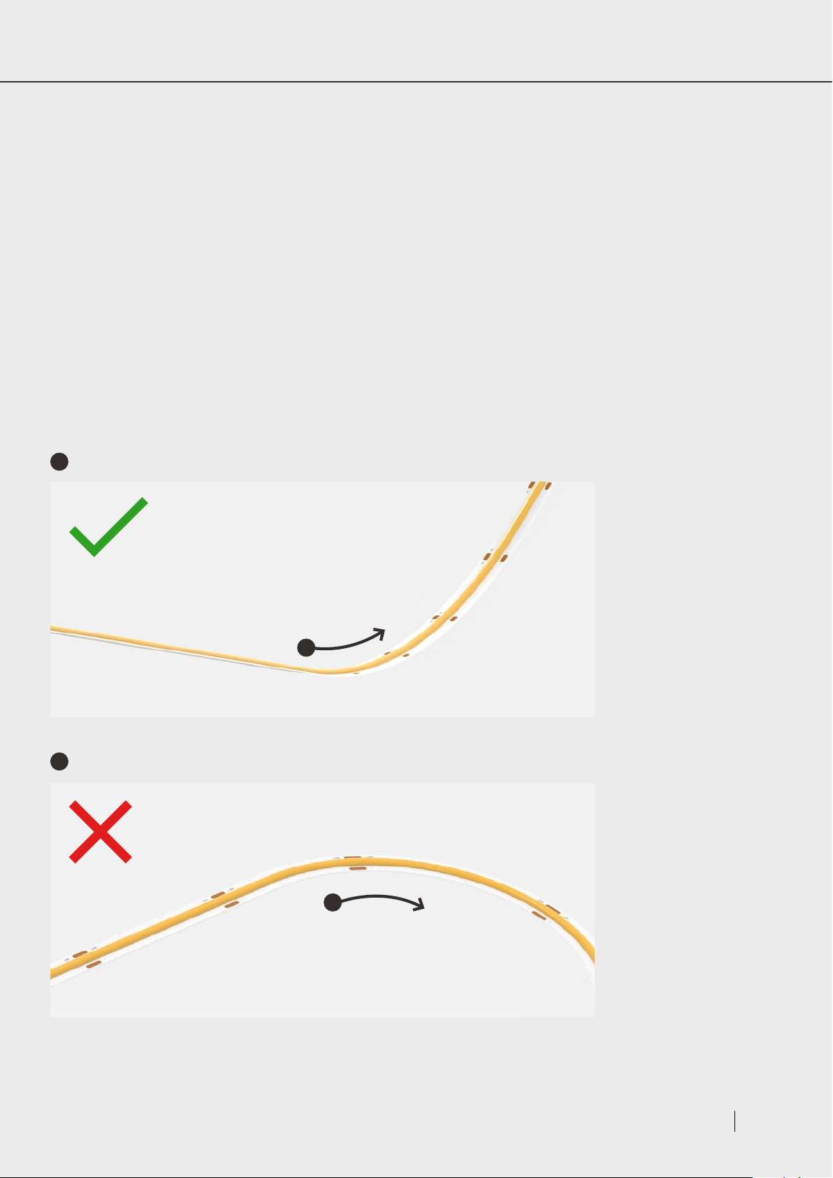
LED Strip is only designed to be installed and manipulated vertically.
a
b
Do not try and bend or curve your LED strip horizontally.
b
Page 3LED Strip Instruction Manual
Page 6
PRECAUTIONS continued
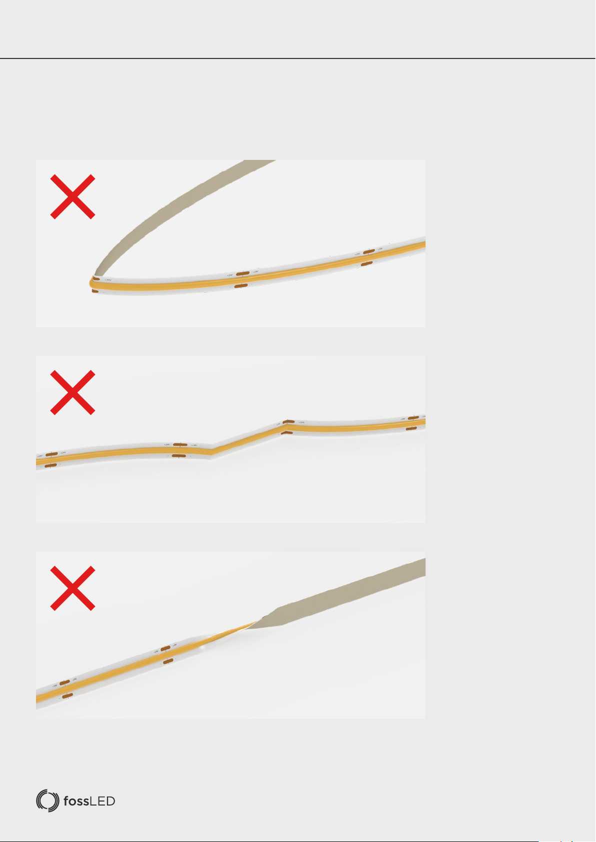
The LED strip can be manipulated vertically, but not bent, distorted or twisted:
Page 7
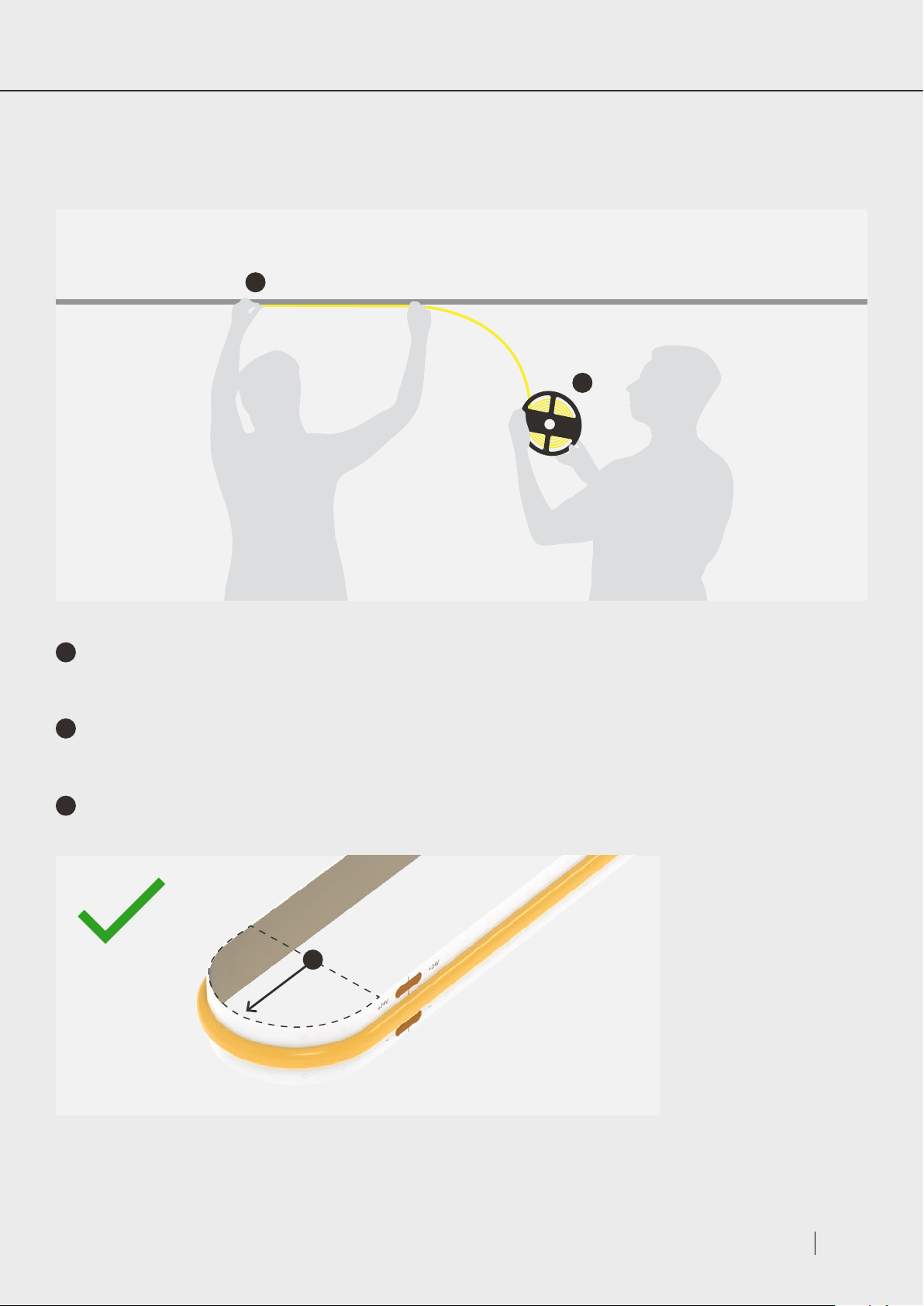
When installing LED Strip care must be taken so as not to inadvertently distort the Strip. If the length of the strip is more than 2
metres then two people must work together for a successful installation.
a
b
a
The installer is to carefully lay the LED Strip into the chosen profile making sure it is lightly pressed into place, avoiding firm
pressure onto LED Chips and components.
b
The assistant is to hold the LED Strip reel and steadily supply Strip as required. This is important to avoid the reel being
dropped or left to hang which can result in Strip failure due to distortion.
c
LED strip has a Max Bend radius of ≥20mm.
c
Page 5LED Strip Instruction Manual
Page 8
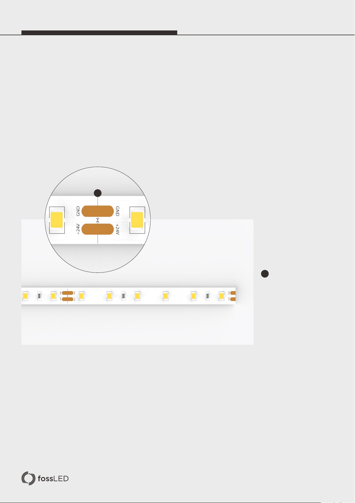
CUTTING
& SEALING
Cutting your LED Strip to Size
LED Strip copper cutting intervals will vary from model to model, please refer to your LED Strip pack or datasheet for exact
interval dimensions.
Once you have calculated and measured out the length of LED Strip you need you may then carefully lay out and cut your
LED Strip.
a
a
Please use sharp scissors
and cut down the cut line,
through the copper cut points.
Page 9
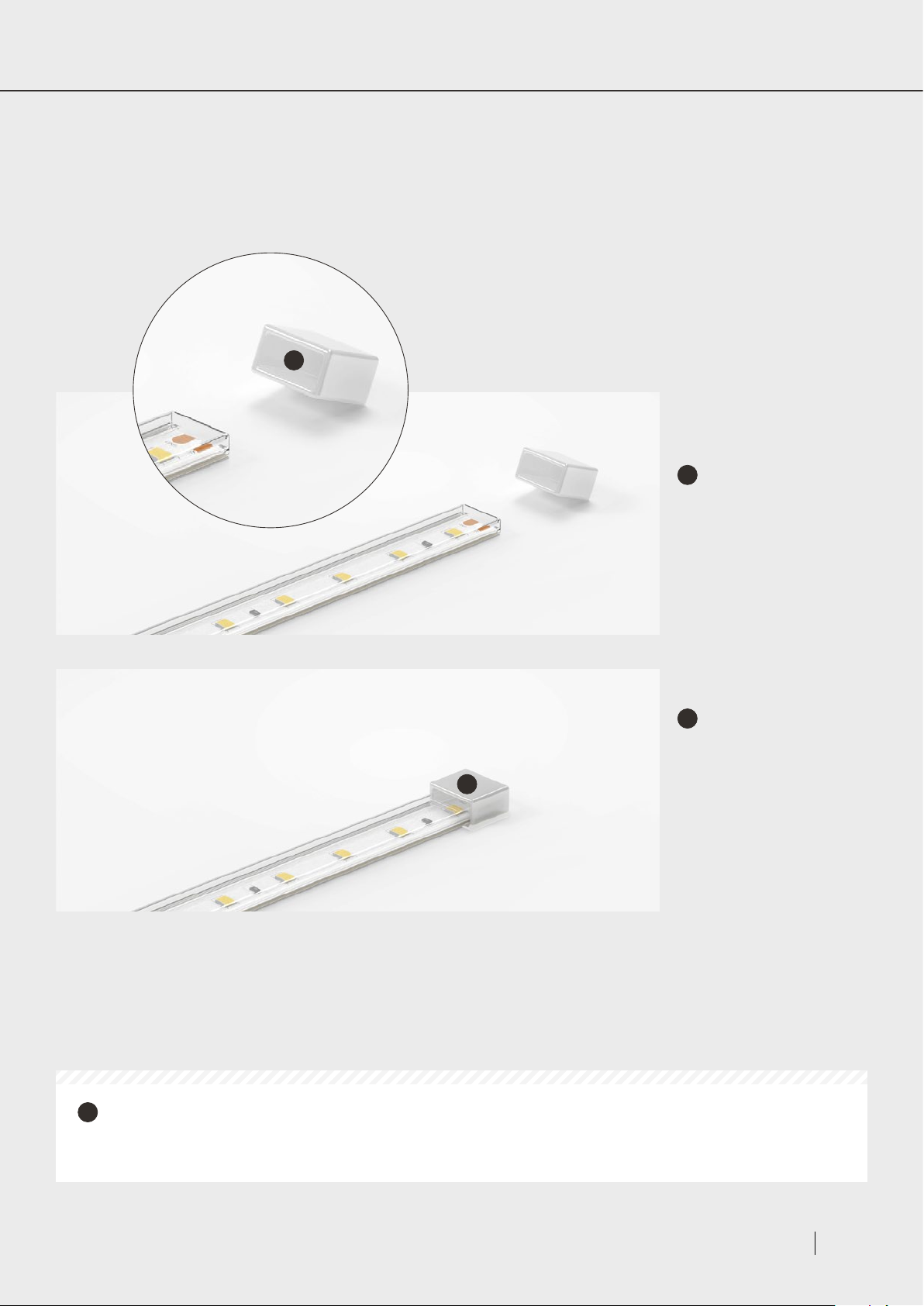
IP65 LED Strip Cutting & Sealing
IP65 LED strip is designed to be used outdoors and is splash proof and non-submersible with its protective Silicone sleeving.
Therefore, when cutting and manipulating a sealed reel of IP65 rated LED Strip it imperative that the Strip sleeving is re-sealed
using Silicone end caps and silicone sealant to avoid permanent damage to your LED Strip.
a
1
2
a
Once you have cut
your LED Strip down to your
chosen copper cut mark, then
carefully fill an end cap with
fossLED Strip Silicon sealant.
a
Place the end cap over
your LED Strip tubing ensuring
it is sufficiently pressed
a
down and covered, please
now leave this to dry for
approximately 24 hours to
ensure a secure IP Rated
finish.
!
We do not recommend customers attempt making LED Strip new feeds or joins whilst trying to maintain an
IP65 rating due to the difficulty of the process, we would however be happy to assist if it is something you require,
please contact [email protected] for further information.
Page 7LED Strip Instruction Manual
Page 10
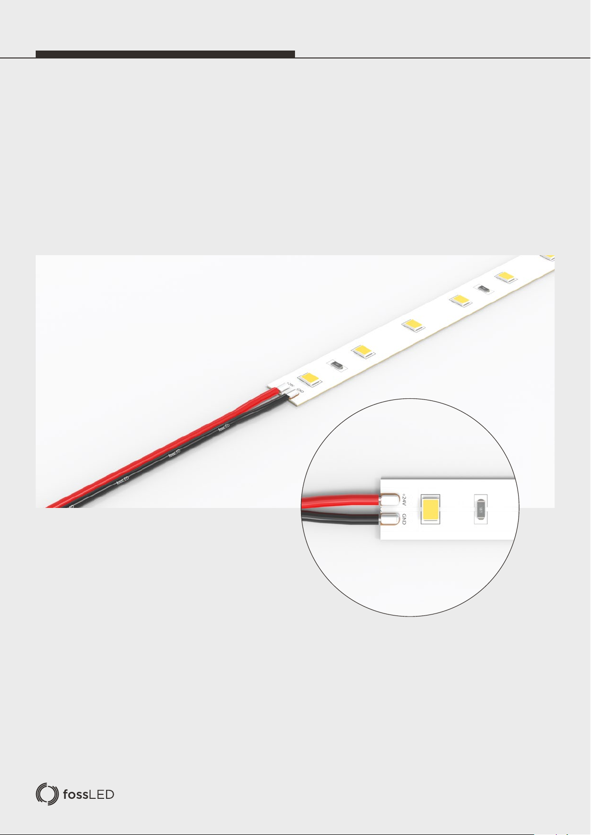
NEW FEED
CONNECTIONS
Soldering on a New Feed
When soldering it is important that the installer is trained to a basic level. Carefully solder suitably prepared cable to the copper
solder pads ensuring sufficient spacing between each connection. Minimize contact time to avoid damaging the LED Strip from
excessive heat and pay attention to the polarities to avoid a reverse connection.
Page 11
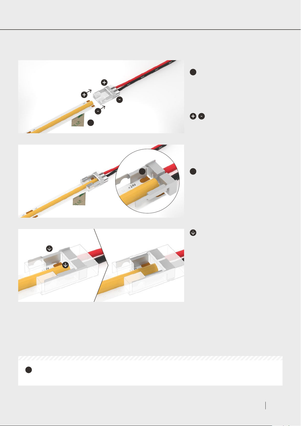
Using a New Feed Clip Connector
Our new feed connectors eliminate the need for soldering, please follow the steps explained below:
a
Peel back the adhesive tape leaving a
1
a
sufficient amount of bare strip to insert into
the clip. Make sure you peel back the tape
and accompanying adhesive layer leaving
this to re-apply once the connection is
complete.
Align the LED Strip ensuring the
polarities match with the feed cable.
2
3
a
a
Insert the LED Strip into the
corresponding terminals ensuring the strip is
fitted correctly so that the copper pads line
up with the clip connector teeth.
Crimp down on the teeth prongs with
pliers to pierce your LED Strip PCB leaving
the prongs flush with the connector housing.
Check the LED Strip is locked in and the
connection is secure.
Re-apply the adhesive tape under the clip
connector ready for installation.
Note: Care must be taken when crimping so
as not to crack the outer housing.
The majority but not all of our LED Strip products have compatible clip connectors as depicted in this user
!
manual, to find out more please visit www.fossLED.com
Page 9LED Strip Instruction Manual
Page 12
STRIP TO STRIP
CONNECTIONS
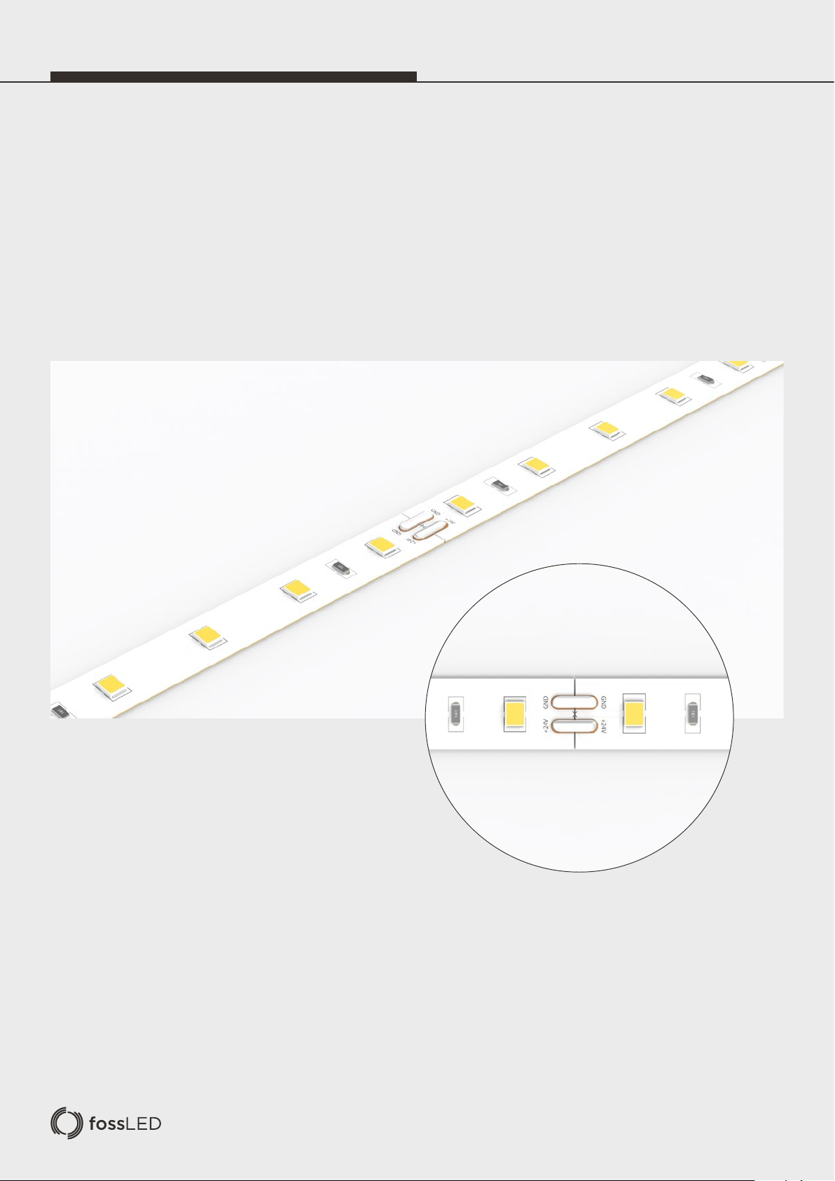
Soldering Two Strips Together
When soldering it is important that the installer is trained to a basic level. Lay your two pieces of LED Strip together so that the
Copper Solder Pads are next to one another and ensure your polarities match. Then apply solder to each pair of copper pads
and connect the strips together taking care to minimize contact time and avoid damaging your LED Strip.
Page 13
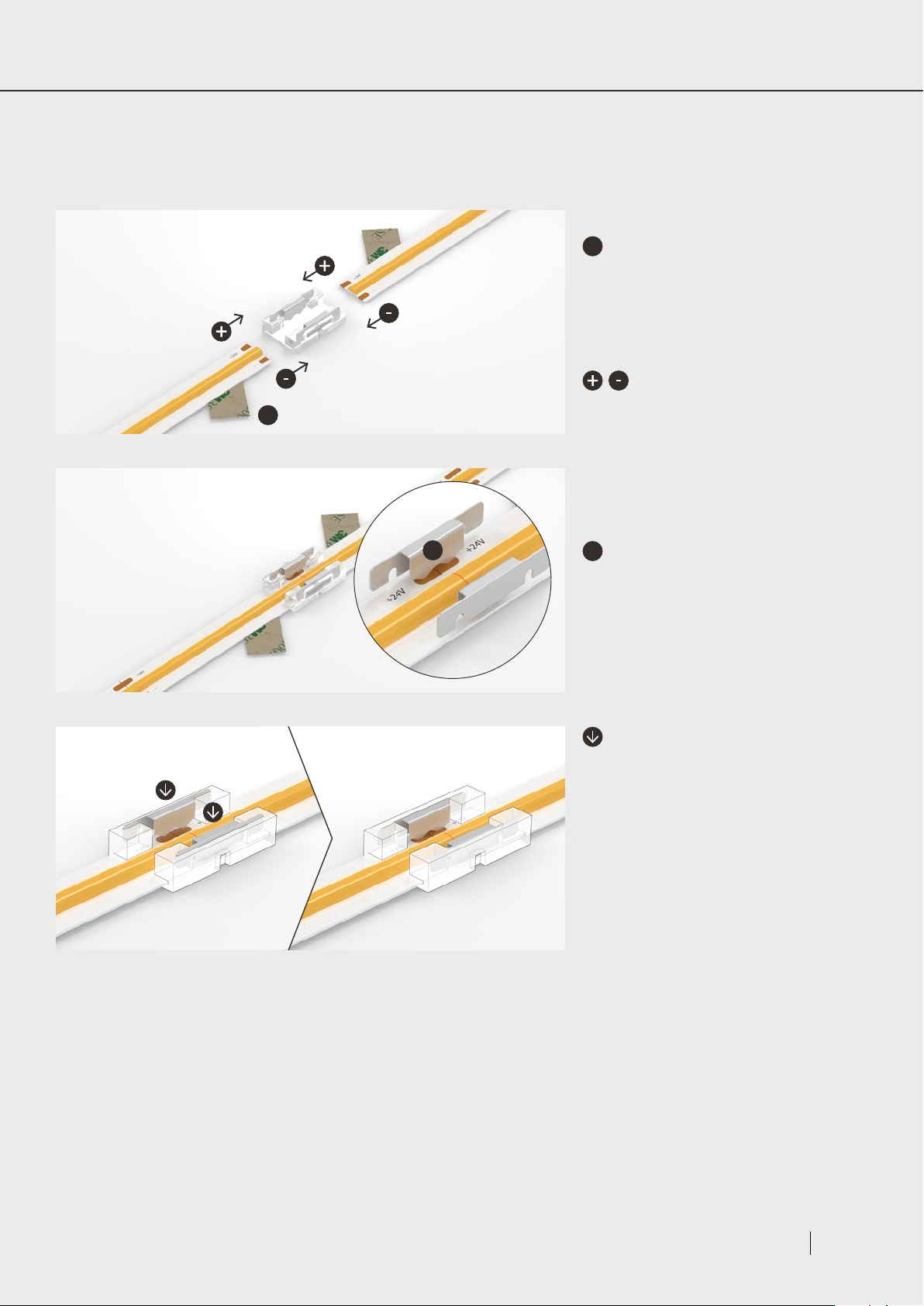
Using a Strip to Strip Clip Connector
Our Strip to Strip connectors eliminate the need for soldering, whilst achieving a gapless connection. Simply follow the steps
explained below:
a
Peel back the adhesive tape leaving a
1
a
sufficient amount of bare strip to reach the
centre of the clip. Make sure you peel back
the tape and accompanying adhesive layer
leaving this to re-apply once the connection
is complete.
Align the LED Strip ensuring the
polarities match.
2
3
a
a
Insert the LED Strips into the
corresponding terminals ensuring both strips
are fitted correctly so that the copper pads
line up with the clip connector teeth.
Crimp down on the teeth prongs with
pliers to pierce your LED Strip PCB leaving
the prongs flush with the connector housing.
Check the LED Strips are locked in and the
connection is secure.
Re-apply the adhesive tape under the clip
connector ready for installation.
Note: Care must be taken when crimping so
as not to crack the outer housing.
Page 11LED Strip Instruction Manual
Page 14
CORNER
CONNECTIONS
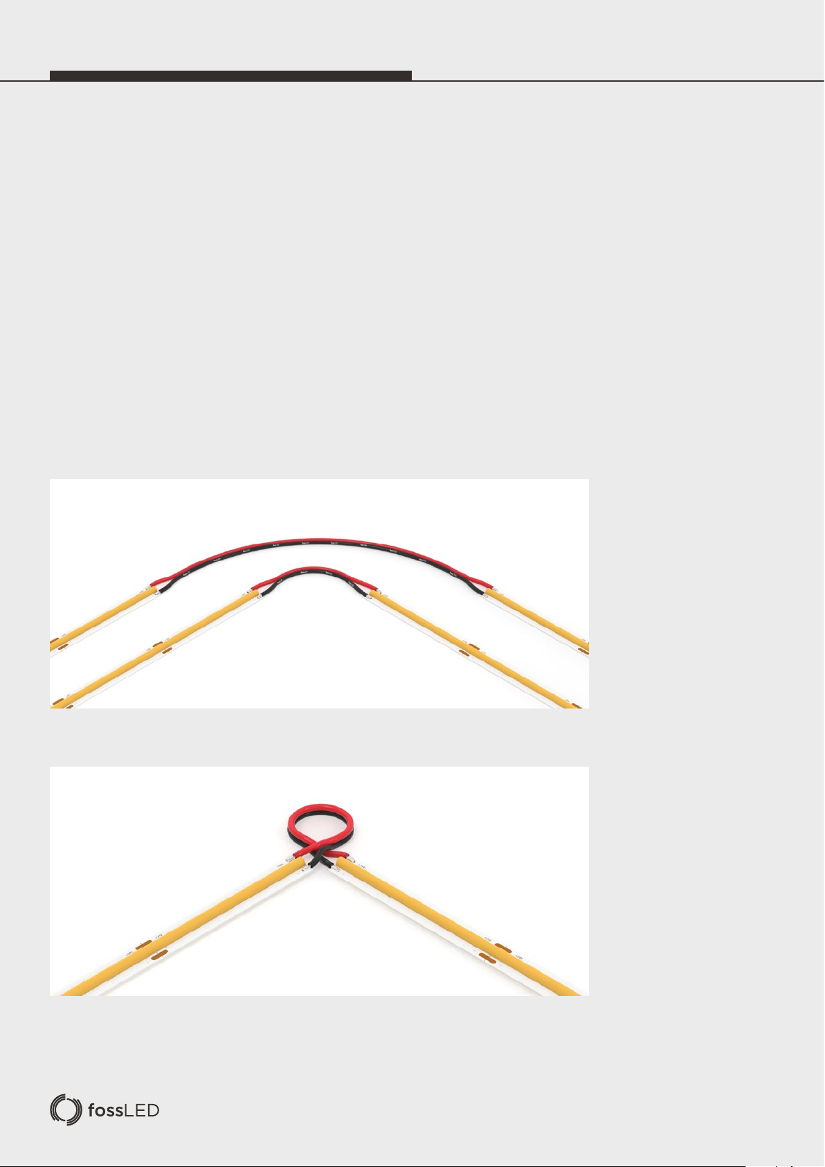
Corner Soldering
Corner solders are important for connecting LED Strips around corners or continuing a connection at a distance or around
obstacles.
When soldering it is important that the installer is trained to a basic level. When making a corner connection please prepare
carefully by ensuring you have a suitable amount of wire between your LED strips ensuring you don’t strain or put pressure on
your connections. Once prepared please align your LED Strips so that your polarities match to avoid a reverse connection and
then solder your wire onto each of the copper pads ensuring sufficient spacing between each connection and minimize contact
time to avoid damaging your LED Strips from excessive heat.
Example 1 - 5cm and 15cm Wire with Gap
Example 2 - 15cm Butted up with Feed Wire Twisted
Page 15
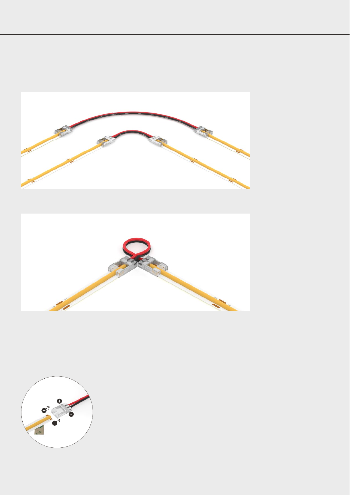
Corner Connectors
Our corner connectors are available with 5cm and 15cm wire feeds to suit different applications
Example 1 - 5cm and 15cm Connection Clip
Example 2 - 15cm Connection Clip Butted up with Feed Wire Twisted
.
For a detailed description of the connection process see
Page 9, “Using a New Feed Clip Connector”.
Page 13LED Strip Instruction Manual
Page 16
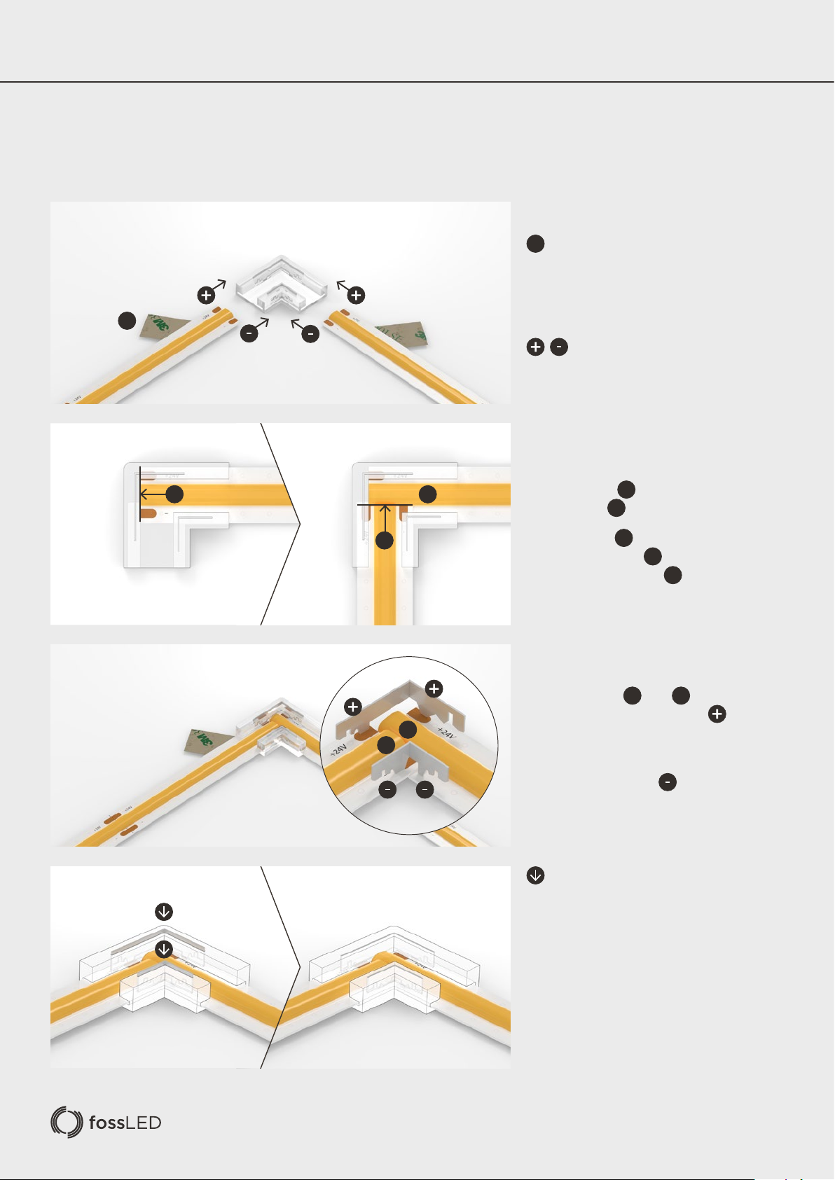
CORNER CONNECTIONS continued
Using a L Clip Connector
L connectors are ideal for when corner connections are on show and you have no room to hide corner connector wires.
a
Peel back the adhesive tape leaving a
1
2
a
1
1
sufficient amount of bare strip to fill the clip.
Make sure you peel back the tape and
accompanying adhesive layer leaving this to
re-apply once the connection is complete.
Align the LED Strip ensuring the
polarities match.
The cutouts within the clip are formed to
allow LED Strip all the way into the clip
and LED Strip to the position shown.
1
2
3
4
2
1
2
Insert LED Strip all the way into the clip.
Then insert LED Strip sufficiently so that
the strip sits above Strip as shown.
Once LED Strips and are fitted
correctly check that the positive copper
terminals align with the corresponding clip
connector teeth as shown.
Note that the negative terminals will also
align as shown.
Crimp down on the teeth prongs with
pliers to pierce your LED Strip PCB leaving
the prongs flush with the connector housing.
Check the LED Strips are locked in and the
connection is secure.
1
2
1
1
2
Re-apply the adhesive tape under the clip
connector ready for installation.
Note: Care must be taken when crimping so
as not to crack the outer housing.
Page 17

POST
INSTALLATION
1. fossLED products are designed to be maintenance free however accumulated dust may be removed from the emitting
surface with careful use of a soft dry cloth.
2. Ensure that paints, organic solvents and caustic or corrosive cleaning chemicals do not come into contact with fossLED
products.
For example, DO NOT USE:
- Benzene, Toluene, Xylene, Acetone, Carbon tetrachloride, Gasoline, Ether.
- Sodium/Calcium hydroxide, Sodium Carbonate.
3. For cleaning or sanitization – products in sealed IP65 rated silicone housings may be wiped with a soft cloth dampened
with water.
4. Please retain this information and pass to those responsible for installation and maintenance.
LED Strip Instruction Manual
Page 15
Page 18

 Loading...