


 Loading...
User Manual
Outdoor HD IP Camera
Model: FI9903P
Model: FI9900P / FI9800P |
Model: FI9900EP / FI9901EP |

Model: FI9803EP |
Model: FI9803P |
Model: FI9804W
Model: FI9805W |
Model: FI9805E |
V3.7.5

Table of Contents |
|
|
Security Warning................................................................................................................................................................... |
1 |
|
1 Overview............................................................................................................................................................................ |
1 |
|
1.1 |
Key Features........................................................................................................................................................... |
1 |
1.2 |
PoE (Power over Ethernet-FI9805E / FI9803EP / FI9900EP / FI9901EP).................................................. |
2 |
1.3 |
Read before Use.................................................................................................................................................... |
2 |
1.4 |
Packing Contents................................................................................................................................................... |
2 |
1.5 |
Physical Description.............................................................................................................................................. |
3 |
1.6 SD Card Management........................................................................................................................................... |
6 |
|
1.7 |
Wall Installation....................................................................................................................................................... |
7 |
1.8 The Different Features between the Models Involved..................................................................................... |
9 |
|
2 Access the IP Camera.................................................................................................................................................... |
10 |
|
2.1 |
Hardware Connection & Software Installation................................................................................................ |
10 |
2.2 Access the Camera In LAN................................................................................................................................ |
10 |
|
2.3 Access the Camera in WAN............................................................................................................................... |
12 |
|
2.4 |
Using the VLC Player.......................................................................................................................................... |
15 |
2.5 |
IP Camera Connection to the Server............................................................................................................... |
17 |
3 Surveillance Software GUI............................................................................................................................................. |
18 |
|
3.1 |
Login Window....................................................................................................................................................... |
18 |
3.2 |
Surveillance Window........................................................................................................................................... |
21 |
4 Advanced Camera Settings........................................................................................................................................... |
28 |
|
4.1 |
Setup Wizard........................................................................................................................................................ |
28 |
4.2 |
Device Status........................................................................................................................................................ |
28 |
4.3 |
Basic Settings....................................................................................................................................................... |
30 |
4.4 |
Network.................................................................................................................................................................. |
37 |
4.5 |
Video...................................................................................................................................................................... |
53 |
4.6 |
Detector................................................................................................................................................................. |
57 |
4.7 |
Record................................................................................................................................................................... |
63 |
4.8 |
PTZ (only FI9805E)............................................................................................................................................. |
67 |
4.9 |
Firewall................................................................................................................................................................... |
67 |
4.10 System................................................................................................................................................................. |
68 |
|
5 Playback (FI9803EP / FI9900P / FI9900EP).............................................................................................................. |
72 |
|
6 Appendix........................................................................................................................................................................... |
74 |
|
6.1 |
Frequently Asked Questions.............................................................................................................................. |
74 |
6.2 |
Default Parameters.............................................................................................................................................. |
80 |
6.3 |
Specification.......................................................................................................................................................... |
80 |
6.4 CE & FCC.............................................................................................................................................................. |
92 |
|
6.5 WARRANTY......................................................................................................................................................... |
93 |
6.6 Statement.............................................................................................................................................................. |
95 |
7 Obtaining Technical Support......................................................................................................................................... |
96 |
Security Warning
1.Please change the password of your camera regularly, using a combination of numbers, letters and special characters.
2.We recommend that you regularly update your camera to the latest available software and firmware versions to help ensure the best experience for your camera.
1 Overview
FOSCAM Outdoor HD IP Camera is an integrated wireless IP Camera with a color CMOS sensor enabling viewing in High Definition resolution.It combines a high quality digital video camera, with a powerful web server, to bring clear video to your desktop from anywhere on your local network or over the Internet.
The IP Camera supports the industry-standard H.264 compression technology, drastically reducing file sizes and conserving valuable network bandwidth.
The IP Camera is based on the TCP / IP standard. There is a WEB server inside which could support Internet Explorer. Therefore the management and maintenance of your device is simplified by using the network to achieve the remote configuration and start-up.
The camera is designed for outdoor surveillance applications such as courtyards, supermarket, and school. Controlling the IP camera and managing images are simplified by using the provided web interface across the network utilizing wireless connectivity.
FOSCAM provides Phone apps for Android and iPhone users, please search and install app on app Store and Google Play for iOS and Android devices, then you can view your camera anywhere, anytime on your smart mobile devices.
1.1 Key Features
Standard H.264 video compression algorithm to satisfy the transmission of high definition video in narrow bandwidth network
1.0 Mega-Pixel (FI9803P, FI9800P, FI9803EP, FI9804W) / 1.3 Mega-Pixel (FI9805W, FI9805E) / 2.0 Mega-Pixel (FI9903P, FI9900P, FI9900EP) / 4.0 Mega-Pixel (FI9901EP)
Supports IE / Firefox / Google / Safari browser or any other standard browsers
Supports WEP,WPA and WPA2 Encryption
Wi-Fi compliant with wireless standards IEEE 802.11b / g / n (FI9804W, FI9805W, FI9803P, FI9800P, FI9900P)
PoE compliant with PoE standards IEEE 802.3af (FI9805E, FI9803EP, FI9900EP, FI9901EP)
IR LEDs for IR range up to 20m / 66ft (FI9803P, FI9800P, FI9900P, FI9900EP, FI9803EP, FI9804W, FI9901EP) / 30m (FI9805W, FI9805E,FI9903P)
Supports image snapshot
Supports dual-stream
Supports IR-Cut and the filter change automatically
1

Embedded FOSCAM DDNS (dynamic domain name service) Service
Supports remote viewing & record from anywhere anytime
Multi-level users management with password protection
Motion detection alert via email or upload image to FTP
Supporting Third Party Domain name
Providing Phone apps for Android and iPhone users
Supports multiple network protocols: HTTP / HTTPS / RTSP / TCP / IP / UDP / FTP / DHCP / DDNS / UPNP / ONVIF
Providing Central Management Software to manage or monitor multi-cameras
Supports magic zoom (FI9900P, FI9900EP, FI9901EP)
Supports High Dynamic Range (FI9900P, FI9900EP, FI9901EP)
1.2 PoE (Power over Ethernet-FI9805E / FI9803EP / FI9900EP / FI9901EP)
The Network Camera is PoE-compliant, allowing transmission of power and data via a single Ethernet cable. Such as the following picture: connect the Network Camera to a PoE-enabled router / switch via Ethernet cable.
1.3 Read before Use
Please first verify that all contents received are complete according to the Package Contents listed below. Before the Network Camera is installed, please carefully read and follow the instructions in the Quick Setup Guide to avoid damage due to faulty assembly and installation. This also ensures the product is used properly as intended.
1.4 Packing Contents
|
IP Camera * 1 |
|
CD * 1 |
|
|
|
|
|
Wi-Fi Antenna * 1 (except for FI9805E, |
|
Quick Setup Guide * 1 |
|
|
|
|
2

|
FI9803EP, FI9903P, FI9900EP, FI9901EP) |
|
|
|
|
|
DC Power Supply * 1 |
Warranty Card * 1 |
|
|
|
|
Mounting Bracket * 1 (except for FI9900P, |
|
|
FI9900EP, FI9800P, FI9901EP) |
|
|
|
|
1.5 Physical Description
1.5.1 Front Panel
Front Panel for FI9804W / FI9805W / FI9805E
 1
1
2
3
4
1 WIFI Antenna: Wireless Antenna (FI9804W, FI9805W)
2 Infrared LED: 12 IR LEDs (FI9804W), 36 IR LEDs (FI9805W, FI9805E) 3 LENS: CMOS sensor with fixed focus lens
4 Induction IC
Front Panel for FI9803EP / FI9803P
 1
1
2 
3 
4
3
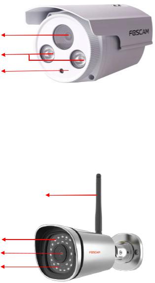
1WIFI Antenna: Wireless Antenna (FI9803P)
2Infrared Lamp Array
3LENS: CMOS sensor with fixed focus lens
4Induction IC
Front Panel for FI9903P
1
2
3
1 LENS: CMOS sensor with fixed focus lens
2 Infrared Lamp Array
3 Induction IC
Front Panel for FI9900P / FI9900EP / FI9800P / FI9901EP
1
2
3
4
1 WIFI Antenna: Wireless Antenna (FI9900P / FI9800P)
2 Infrared LED: 30 IR LEDs
3LENS: CMOS sensor
4Induction IC
4

1.5.2 Interface
1
2
3
4
5
6
7
1 I / O alarm terminal block (Only FI9805E)
This network camera provides a I/O alarm terminal block which is used to connect to external input / output device.
The pin (there are four number in the terminal block from no. 1 to no. 4) definitions are as follows:
1– input 2- input 3- output 4- output
This camera supports I/O alarm, you can go to Settings-Alarm - I/O page to configure it.
2 LAN
10/100M adaptive Ethernet interface. Through this interface, IP camera can be connected with various network devices, such as hub, router, etc.
3 Reset button
Press and hold on the reset button for 5 seconds. Releasing the reset button, the password will back to the factory default administrator password. The default administrator user is admin with no password.
4 Power Interface
5
Connect the external power adapter, request for 12V / 2A or 12V / 1A power.
5 Audio input interface (Except FI9803EP / FI9803P / FI9903P)
The jack is used to plug external input device such as sound pick up device directly. Here microphone cannot directly insert to the interface, it must connect to adapter first.
6 Audio output interface (Except FI9803EP / FI9803P / FI9903P)
The jack is used to plug external output device such as loud speaker directly. Here microphone cannot directly insert to the interface, it must connect to adapter first.
7 RS485 Cradle head interface (Only forFI9805E)
This camera supports the standard 485 cradle head protocol (Pelco-D and Pelco-P). Please configure the RS485 protocol corresponding information first (go to SettingsPTZ - RS485 Configuration page and do settings), or else the cradle head may cannot work.
1.5.3 Bottom View
There are up to two labels located at the bottom of the camera, this is an important feature of original Foscam cameras. If your camera does not have labels, it may be a clone. Cloned Foscam cameras can not use original firmware and are not eligible for warranty or technical services.
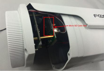
1.6 SD Card Management
The record files of the IPC can be stored in the SD Card.
You need open the IP Camera, then plug the SD card into SD card slot inside the IP Camera.
When you plug in the SD card during the camera work process, please reboot the camera again, or else the SD Card may be cannot work well.
Insert Micro SD Card in the location shown below.
FI9803EP
6
FI9901EP / FI9900P / FI9900EP
NOTE: When you re-install the camera, please ensure the tightness with the camera.
1.7 Wall Installation
FI9803EP / FI9803P / FI9903P
Step 1: Screw the mount on the wall with the 3 screws provided.
Step 2: Install the camera on the mounting bracket with 1 screw to complete installation.
FI9800P / FI9900P / FI9900EP / FI9901EP
7
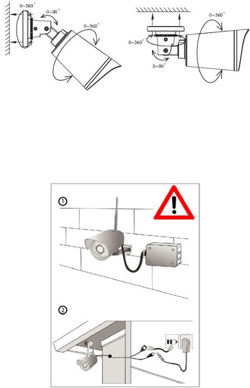
Fixate the camera on your preferred location and use screws to mount it. We have provided screws in the Packaging.
NOTE: Ensure that the rain or water will not reach the connector ports at the end of the pig tail wiring. These connectors are not weather-resistant.
The cable of an outdoor camera should, from the position where the cable is divided into several cables, be fitted dry. Install the cable into a waterproof junction box (1) or bring the cable indoors (2).
8

1.8 The Different Features between the Models Involved
Differences
Model |
Wireless |
PoE (Power over |
Alarm In / Out |
Audio Input / Output |
RS485 |
P2P |
|
|
Ethernet) |
|
|
|
|
FI9804W |
|
|
|
|
|
|
FI9805W |
|
|
|
|
|
|
FI9805E |
|
|
|
|
|
|
FI9803EP |
|
|
|
|
|
|
FI9803P |
|
|
|
|
|
|
FI9903P |
|
|
|
|
|
|
FI9900P |
|
|
|
|
|
|
FI9900EP |
|
|
|
|
|
|
FI9800P |
|
|
|
|
|
|
FI9901EP |
|
|
|
|
|
|
9

2 Access the IP Camera
2.1 Hardware Connection & Software Installation
1.Mount the antenna and make it stand vertically (Only for the device with external antenna).
2.Connect the camera to the LAN network (Router or Switch) via network cable.
3.Connect the power adapter to the camera.
4.Insert the CD into the CD drive of your computer.
5.Go to the folder "Equipment Search Tool" and find the folder For "Windows OS" or "For Mac OS". Copy and paste the search tool file to your computer, or drag it onto your Desktop.
NOTES:
If your computer (Windows OS) supports autorun function, you can find the corresponding file in the opened control panel.
If your computer doesn't have CD drive, you can download the Equipment Search Tool from our website for free.
2.2 Access the Camera In LAN
2.2.1 Wired Connection
The camera supports HTTP and HTTPS protocols, you can access the camera in two ways.
(1) Http:// LAN IP + Http Port No.
The default HTTP port NO. is 88. Double click the Search Tool icon to run, and it should find the camera's IP address automatically after you plug in the network cable.
10

Double click the IP address of the camera; the camera login page should be open in your default browser.
(2) Https:// LAN IP + Https Port no.
The default HTTPS port NO. is 443. You can use the URL to access the camera: https:// LAN IP + HTTPS port NO.
Go to Settings - Network - Port panel, you can see and change the HTTP and HTTPS port NO.
NOTE: When logging in for the first time, you will need to download and install the add-on.
2.2.2 Wireless Connection
Only some models support EZLink wireless connection , please refer to the Quick Setup Guide.
11
2.3 Access the Camera in WAN
2.3.1 Static IP Addresses
Users who have static IP addresses do not need to set DDNS service settings for remote access. When you have finished connecting the camera using the LAN IP address and port forwarding, you can access the camera directly from the Internet using the WAN IP address and port number.
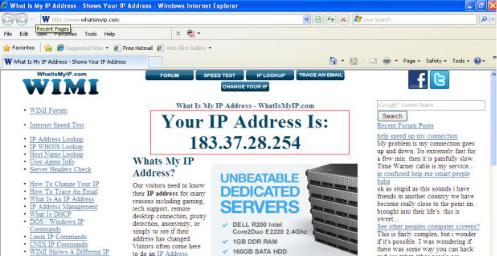
How to Obtain the WAN IP address from a public website ?
To obtain your WAN IP address, enter the following URL in your browser: http://www.whatismyip.com.The webpage at this address will show you the current WAN IP.
Access your IP Camera from the Internet
You can access the IP Camera from the Internet (remote access). Enter the WAN IP address and port number in your standard browser. For example, you would enter http:// 183.37.28.254:88
2.3.2 Remote Access
If you want to access your camera by web browser outside of your LAN, you need to configure following configurations.
1. Choose Settings on the top of the camera web page, then go to the Network > IP Configuration section on the left side of the screen, then uncheck the Obtain IP DHCP.
12

IP Address: Set this in the same subnet as your computer , or keep it as default. Subnet Mask: Keep it as default.
Gateway and DNS Server: Set it to the IP address of your router.
2. Enable UPnP and DDNS in the camera's settings page. We recommend you to use the DDNS by factory default.
Select Yes and click Save.
Click Enable DDNS and click Save. The content in the Manufacture’s DDNS
column is the domain name of your camera.
3. You can see the port of your camera here. If you want to set Remote Access for several cameras on the same network, you will need to change the HTTPS port for each camera.
4. If the UPnP of the router has been enable, you do not need to perform following steps. Otherwise, you need to select one of the following methods to configure port forwarding on your router. For these steps, we will
13

be using the TP-LINK brand wireless router as an example.
If there is a UPnP function in your router:
Choose Forwarding > UPnP, make sure that the Current UPnP Status is Enabled.
If there is no UPnP function in your router:
You need to manually add port (HTTPS port) forwarding, refer to the following steps. You need go to the
Forwarding > Virtual Servers panel for setup.
Click Add New.
Input the port and IP address of your camera and click Save.
14
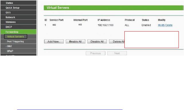
Here you have finished the
Port Forwarding setup.
5.Now you can access your IP camera by https://domain name: HTTPS port via the Internet.
2.4 Using the VLC Player
This camera supports RTSP streaming, here you can view the camera using VLC player.
RTSP URL rtsp:// [user name][:password]@IP:port number/videosream
The part in the square brackets may be omitted. user name & password:
The user name and password to access the camera. This part can be omitted. IP: WAN or LAN IP address.
port number: If there is the RSTP port number on the Port page, you must only use RTSP port number. otherwise, you must only use http port number.
Videostream: Here support three modes: videoMain, videoSub and audio. When the network speed is bad, here you had better select videoSub. If you select audio, you can only hear the sound but cannot see the video.
For example:
IP: 192.168.1.11
Port number: 88
User name: admin
Password: 123
Here I can enter one of the following URLs in the VLC. 1 rtsp://admin:123@192.168.1.11:88/videoMain 2 rtsp:// @192.168.1.11:88/videoMain 3 rtsp://:123@192.168.1.11:88/videoMain 4 rtsp://admin@192.168.1.11:88/videoMain
Open the VLC, and go to Media (Open Network Stream option, then enter the URL into VLC.
15

Sometimes you may need to enter the user name and password again. Click OK and you can see the real-time
16
preview.
If you cannot play the video in the VLC player, please check the port mapping.
NOTE: If you modify the camera's username or password, you had better reboot the camera, or else the new username and password cannot take effect when you enter the authentication in the VLC.
2.5 IP Camera Connection to the Server
Device supports ONVIF 2.2.1 protocol,You can easily access the NVR with ONVIF or server with ONVIF.
17

3 Surveillance Software GUI
Please refer to the section 2.1 if you install the camera for the first time. You can start to learn about software operation after finish quick installation.
3.1 Login Window
Section1 Enter the Username and password
The default administrator username is admin with no password, please change the password at first using and prevent unauthorized users login the camera.
Section2 Stream
The camera supports two stream modes: Main stream and sub stream. If you want to access the camera form LAN, here you can select Main stream. If you want to access the camera from Internet, here we recommend sub stream.
NOTE: When the network bandwidth is bad you'd better select Sub Stream and the video will be more fluent.
Section3 Select the language
You can select the language you need by clicking on the language dropdown list.
Section4 login the camera
Click Login button.
NOTE: When setting up your camera for the first time, it will request that you modify the default username and / or password if both are still set to default. Input the new username and password, click Modify to complete the modification. You will now use the new username and password to login the camera in the future.
18
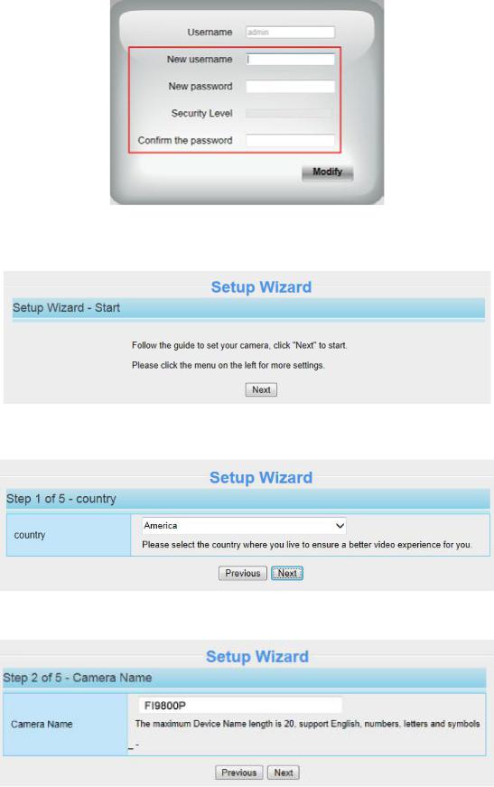
After logging in for the first time, you will go to Setup Wizard automatically. Here you can set the basic parameters of camera, such as camera name, camera time, wireless settings, IP configuration.
Country: Select the country.
Device Name: You could give name for your camera.
System Time: Select the time zone you need to set the date, time,format, etc.
19

Wireless networks: Click Scan, find the SSID of your wireless router, select and enter the password.
IP: Set IP address of the camera. You could choose to obtain an IP automatically or set the IP address according to your needs.
20

NOTE: It needs about 1 minute to connect the camera to your router.
3.2 Surveillance Window
1
2
 8
8
3
4
5
6
7
|
|
9 |
Differences |
|
|
Model |
Playback WDR |
Pan / Tilt Control Zoom out / Zoom in Cruise |
FI9804W
FI9805W
FI9805E
FI9803EP
FI9803P
FI9903P
21

FI9900P
FI9900EP
FI9800P
FI9901EP
Section1 FOSCAM Logo / LiveVideo / Settings buttons
 : FOSCAM LOGO
 : Path to surveillance window. Click this button and back to the surveillance window
 : Path to Administrator Control Panel, Click it, and it will lead to Administrator Control Panel and do advanced settings.
Section2 Multi-Device Window
The firmware inside the camera supports up to maximum of 9 cameras being monitoring at the same time. You can add other cameras in multi-camera panel.
Section3 Mode / Stream / WDR / NAA / Mirror / Flip buttons
Mode
1)50Hz ---------Indoor surveillance (Region: Europe, China)
2)60Hz ---------Indoor surveillance (Region: USA, Canada)
3)Outdoor Mode------Outdoor surveillance
Stream
The default stream supports multiple modes, For example: Equilibrium Mode / 720P / 15fps / 512K meanings:
Stream type / Resolution / Maximum frame rate / Bit rate. (Different models support different specific mode. )
1)Stream type no. Identify the stream type.
2)Resolution
The bigger the resolution, the better of the image quality is. If you are accessing the camera via internet and want to get more fluent video streaming, please select resolution VGA.
3) Maximum frame rate
The maximum frame rate is 30 fps. You should lower frame rate when the bandwidth is limited. Normally, when the frame rate above 15, you can achieve fluently video. The maximum frame rate for each model is different, please refer to 6.3 Specification.
4) Bit Rate
Generally speaking, the larger the bit rate is, the clearer video will become. But the bit rate configuration should combine well with the network bandwidth. When the bandwidth is very narrow, and bit rate is large, that will lead to video cannot play well.
You can reset the stream type on Settings > Video > Video Settings panel.
22

WDR (Only FI9900P, FI9900EP, FI9901EP): WDR stands for High Dynamic Range. It usually refers to the method of capturing images having "greater dynamic range between the lightest and darkest areas of an image than current standard digital imaging methods or photographic methods". You can select ON from the dropdown list under sunlight or with bright background.
NAA (except FI9804W / FI9805W / FI9805E): NAA (Network Auto-Adaptability) can make IP Camera changing the real-time rate to adapt different network conditions, which can supply better preview experience. It is OFF as default.
"Zoom in" or "Zoom out" (FI9900P, FI9900EP, FI9901EP)
Device Support 8x zoom feature, click  or
or  ,The focal length of the camera lens will be larger or shrink, you can adjust the focus distance to the target object size, access to high-definition screen.
Section4 Pan / Tilt Control (only F9805E)
When via RS485 interface to connect an external PTZ device, you can use this feature.
|
|
1 |
|
|
3 |
4 |
|
|
|
2 |
|
1------ |
Up control button, |
2------ |
Down control button, |
3------ |
Left control button, |
4------ |
Right control button, |
Click this button and go to center
23

Section5 Cruise settings ( only F9805E)
If via RS485 interface to connect an external PT device, you can use this feature.
The default cruise tracks have two types: Vertical and Horizontal.
Vertical: The camera will rotate from up to down.
Horizontal: The camera will rotate from left to right.
: Start cruise. |
: Stop cruise. |
If you want to define or change the cruise trace, please go to Settings PTZ
PTZ Preset Settings panel.
How to do cruise?
Firstly: Select one track in the track drop-down list
Select one of these
Secondly: Click Start cruise button, the camera will cruise following the predefined path.
Thirdly: Click stop button and finish cruising.
Section6 IR LED Lights
Click Infra led and there are three modes to adjust the infrared led: Auto, Manual and Schedule. Auto: Select it and the camera will adjust the infra led (on or off) automatically.
Manual: Select it and turn off the infra led manually.
Schedule: Select it and the IR led light will be off at the schedule period. If you want to define or change the IR led lights schedule time, please go to Settings > Video > IR LED Schedule page.
24

Section7 Image quality settings
In this page, you can tune Hue, Brightness, Contrast, Saturation, and Sharpness to get higher quality.
Section8 OSD
If you have added time and camera name in the video, you can see it in the live window.
Go to Settings > Basic settings > Camera name panel, and you can change another device name. The default device name is anonymous.
Go to Settings > Basic settings > Camera time panel and adjust the device time. Go to Settings > Video > On Screen Display panel, you can add or no add OSD.
Section9 Play / Stop / Talk / Audio / Snap / Record / Full screen button
|
1 |
2 |
3 |
4 |
5 |
6 |
7 |
8 |
1------ |
Play Click it to play the video of the camera |
|
|
|
||||
2------ |
Stop Click it to stop the video of the camera |
|
|
|
||||
3------ |
Talk Click the button and the icon will become to |
, then talk to the microphone that connected with |
||||||
PC, people around the camera can hear your voice if the camera has connected with audio output device. Click the icon again and stop talking.
4------ |
Audio Click the button and the icon will become to |
, you can hear the sound around the camera if |
the camera has connected with other audio input device through the Audio Input port of the camera, Click the icon again and stop audio.
5----- |
Volume Click the button and the icon will become to |
, you can set the volume. |
|
6----- |
Snap Click it to make snapshot and it pop up a window which picture you snapshot, right click in the |
||
window and save the picture to anywhere you want. |
|
||
7----- |
Record Click the icon |
and the camera start recording, you can see a green dot in the live window. |
|
Click again and stop recording. The default storage path is C:\IPCamRecord. You can change the storage path: Go to Settings > Record > Storage Location panel.
25

8------Full Screen Click it to make full-screen, or you can double click the surveillance screen to make full-screen. Double click again and exit full-screen.
Onscreen Mouse Control
Right click the mouse and you can adjust the screen ration, full screen and Zoom up.
Keep Ration: Select it and the camera will adjust the size of live window based on the computer monitor automatically.
Sometimes there is a black border around the video, please select Keep ration to get a better visual quality.
26
Loading...