

Page 1

OPERATOR’S MANUAL
FORWARDER
2546/2548
Part No. 30012734
February 2012
Rev. C
Page 2

Page 3

TO THE OPERATOR
2546/2548 T3 1108
i
Page 4

TO THE OPERATOR
2546/2548 T3
ii
1108
Page 5
TO THE OPERATOR
TO THE OPERATOR
INTRODUCTION
DO NOT USE THIS MACHINE UNLESS YOU HAVE READ AND UNDERSTAND THIS MANUAL,
AND HAVE THE NECESSARY TRAINING AND AUTHORIZATION TO OPERATE AND MAINTAIN YOUR MACHINE PROPERLY.
REMEMBER THAT YOU ARE THE KEY TO SAFETY. GOOD SAFETY PRACTICES PROTECT
YOU AND THE PEOPLE AROUND YOU. MAKE THIS MANUAL A WORKING PART OF YOUR
SAFETY PROGRAM.
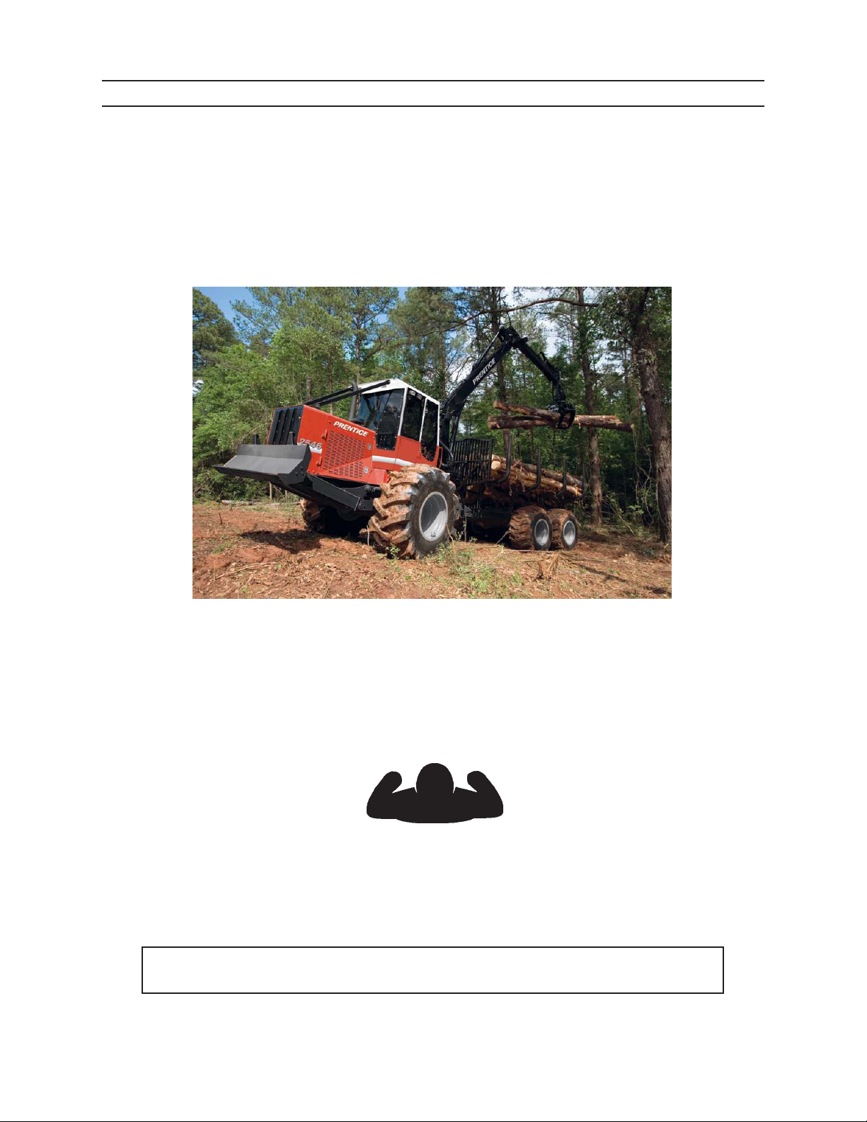
2546/2548 CAT Forwarder
To safely operate this machine, follow the instructions in this operator’s manual. Directions in this manual are
referenced from the operator’s seat facing forward (see diagram below).
FORWARD
LEFT RIGHT
REAR
You can help improve this manual. If you nd any mistakes, or if you know of a way to improve procedures,
please let us know. Mail your suggestions or comments to the attention of Technical Publications, Caterpillar
Forest Products, Inc., 3249 South County Road 45, PO Box 568, Owatonna, MN 55060-0568.
This operator’s manual includes information available and current at the time of approval for printing.
Caterpillar Forest Products, Inc., reserves the right to improve its product without giving prior notice or
incurring obligation.
This operator’s manual should be regarded as part of the machine. Suppliers of both new and second hand
machines are advised to retain documentary evidence that this manual was provided with the machine.
2546/2548 T3 1108
iii
Page 6

TO THE OPERATOR
CAUTION
NOTICE
DANGER
WARNING
SAFETY SYMBOLS
SAFETY ALERT SYMBOL
The Safety Alert Symbol means
ATTENTION!
BE ALERT!
YOUR SAFETY IS INVOLVED!
This safety symbol is used to convey important safety messages. To
avoid personal injury and/or property damage, when you see this
symbol, follow the corresponding safety message.
Understand signal words: DANGER, WARNING, and
CAUTION are used with the SAFETY ALERT SYMBOL.
DANGER IDENTIFIES A HAZARD OR UNSAFE
PRACTICE THAT WILL RESULT IN SEVERE PERSON
AL INJURY OR DEATH.
WARNING identies a hazard or unsafe practice
that could result in severe personal injury or death.
CAUTION identies a hazard or unsafe practice that
could result in personal injury or property damage.
2546/2548 T3
NOTICE identies important installation, operation, or
maintenance information.
iv
1108
Page 7

TO THE OPERATOR
CONTENTS
PRODUCT PROTECTION PLAN .............................................i
Machine ................................................................................i
TO THE OPERATOR ..................................................................iii
Safety Symbols .................................................................iv
GENERAL SAFETY .................................................................11
Safety Alert Symbol .....................................................1-1
Operator Preparation ..................................................1-1
Battery Safety .................................................................1-2
Cooling Fan .....................................................................1-2
Discharge Accumulator ..............................................1-3
Electric Lines ...................................................................1-3
Electrical Storm .............................................................1-4
Falling or Swinging Logs ............................................1-4
Fire Prevention/First Aid .............................................1-5
Fluids Under Pressure..................................................1-6
Hand Signals ...................................................................1-6
Hand Holds and Steps .................................................1-7
Hoses and Fittings ........................................................1-7
No Riders on Machine ................................................. 1-8
Mechanical Cab Tilt Lock ............................................1-8
Operator Safety .............................................................1-9
Practice Safe Maintenance ........................................1-9
Pinch Points ................................................................. 1-10
Pressure Settings .......................................................1-10
Protective Clothing ...................................................1-10
Protective Devices/Equipment ............................. 1-11
Radiator Cap ................................................................ 1-11
Refueling ....................................................................... 1-11
ROPS/FOPS/OPS Cab Structure ............................ 1-12
Servicing Control Valves, Cylinders, Pumps and
Motors ................................................................... 1-12
Seat Belt ........................................................................1-12
Servicing Machine with Engine Running .......... 1-13
Slope Operation ......................................................... 1-13
Starter Circuitry .......................................................... 1-14
Unauthorized Welding ............................................. 1-14
Tire Safety ..................................................................... 1-14
Use Steering (frame) Lock ....................................... 1-15
SAFETY DECALS ....................................................................21
Forwarder Exterior........................................................2-1
Forwarder Interior ........................................................2-2
COMPONENT TERMINOLOGY ..........................................31
Forwarder ........................................................................3-1
IQAN® .........................................................................................41
Main Screen ..............................................................4-1 - 2
Settings Screen ........................................................4-3 - 9
LCD/Lighting Setting ..........................................4-4
Language Setting ................................................4-5
2546/2548 T3 1108
Alarm/Sound Setting ..........................................4-6
IQAN® .....................................................................CONT.
Button (Key) Setting ............................................4-7
Date/Time Setting ...........................................4-8-9
Measure Screen ..................................................4-10 - 16
Voltage Input Measure .................................... 4-11
Digital Input Measure ...................................... 4-12
Frequency Input Measure .............................. 4-13
Direction Input Measure ................................ 4-14
Current Output Measure ................................4-15
Digit Output Measure ...................................... 4-16
Mode Screen .......................................................4-17 - 19
Copy Mode ..........................................................4-18
Reset Mode ......................................................... 4-19
Information Screen ...........................................4-20 - 23
Properties Screen ...............................................4-24 - 25
CONTROLS AND INSTRUMENTS .....................................51
Operator’s Station ........................................................5-1
Gauge Cluster Assembly ............................................5-2
Warning Indicator Panel .............................................5-3
Left Side Console ..........................................................5-4
Right Side Console .......................................................5-5
Rear Console ...................................................................5-5
Satellite Radio ................................................................5-6
Blade Control ..................................................................5-7
Axle Dierential Lock ..................................................5-8
Battery Disconnect Master Switches .....................5-9
Brake Low Pressure Indicator ................................ 5-10
Cab Tilt Control ........................................................... 5-10
Climate Controls......................................................... 5-11
Emergency Exits ......................................................... 5-11
Engine Oil Pressure Gauge ..................................... 5-12
Engine Temperature Gauge ................................... 5-12
Frame Lock Switch..................................................... 5-13
Fuel Indicator .............................................................. 5-13
Fuse and Relay Panel ................................................ 5-14
Hourmeter .................................................................... 5-14
Hydraulic Oil Temperature Indicator .................. 5-15
Hydraulic Oil Low Flow Indicator ......................... 5-15
Hydraulic Reservoir Sight Gauge .........................5-16
Ignition Switch ............................................................ 5-16
Iqan ........................................................................5-16
Joystick Function - Forward Facing ..................... 5-17
Forestry Joystick Function - Rear Facing ........... 5-18
SAE Joystick Function - Rear Facing .................... 5-19
Load Sense Dump Valve ......................................... 5-20
Operating Lights Switch ....................................5-21-22
Operator’s Seat ..................................................... 5-23-24
Park Brake ..................................................................... 5-25
Power Outlets .............................................................. 5-25
v
Page 8

CONTENTS
TO THE OPERATOR
CONTROLS AND INSTRUMENTS ...............................CONT.
Seat Belt ........................................................................5-26
Seat Proximity Switch ............................................... 5-26
Steering (Default) ...................................................... 5-27
Steering (Optional) .................................................... 5-28
Steering Lock ............................................................... 5-29
Tachometer .................................................................. 5-30
Throttle ........................................................................ 5-31
Transmission Controls .............................................. 5-32
Transmission Display Panel .................................... 5-33
Transmission Oil Temperature Gauge ................ 5-33
Pedals ........................................................................ 5-34
Windshield Wiper ....................................................... 5-35
PRESTART INSPECTION .....................................................61
Pre-start Checks: On the Ground ............................6-1
Pre-start Checks: In the Cab ......................................6-2
Fire Prevention ...............................................................6-3
OPERATION
General Guidelines .......................................................7-1
Getting on Machine .....................................................7-2
Starting the Engine ................................................7-3 - 4
Cold Weather Starting .................................................7-5
Jump-starting Battery .................................................7-6
Warm-up Period ............................................................7-7
Axle Dierential Lock ..................................................7-8
Blade Operation ............................................................7-9
Bogie Axle Lift Operation ........................................ 7-10
Slope Operation ......................................................... 7-11
Travel Operation......................................................... 7-12
Driving the Forwarder ...................................... 7-13 - 14
Stopping the Forwarder .......................................... 7-15
Stopping the Engine/Parking the Machine ...... 7-16
Tilting the Cab.....................................................7-18 - 21
Getting O Machine ................................................ 7-22
BREAKIN PERIOD .................................................................81
TRANSPORTING ....................................................................91
FUELS AND LUBRICANTS ................................................ 101
Fuel ........................................................................ 10-1
Engine Oil ..................................................................... 10-2
Hydraulic Oil ................................................................ 10-3
Grease ........................................................................ 10-3
Axle Fluids .................................................................... 10-4
Swing Drive Grease ................................................... 10-4
Pinion & Swing Gear Lubricant ............................. 10-4
Swing Drive Gear Box Lubricant ........................... 10-4
Corrosion Preventive, Cylinder Rod ....................10-4
Transmission Fluid ..................................................... 10-5
Storing Lubricants ..................................................... 10-5
MAINTENANCE SAFETY .................................................. 111
Before Maintenance............................................ 11-1 - 5
Practice Safe Maintenance ............................11-1
Accumulator/Hydraulic Safety .....................11-2
Steering Lock ...................................................... 11-3
Blade Safety ........................................................ 11-3
Boom Safety ........................................................ 11-4
Protective Clothing ..........................................11-4
Servicing Control Valves, Cylinders, Pumps
and Motors ................................................. 11-4
Unauthorized Welding ....................................11-5
During Maintenance .......................................... 11-6 - 8
Battery Safety .....................................................11-6
Cooling Fan ......................................................... 11-6
Diesel Exhaust .................................................... 11-7
Fluids Under Pressure ...................................... 11-7
Fuels and Lubricants ........................................ 11-7
Pinch Points ......................................................... 11-8
Servicing Machine with Engine Running . 11-8
Tier Safety ............................................................ 11-8
After Maintenance .................................................... 11-9
Disposing of Waste ...........................................11-9
Storing Flammable Materials ........................ 11-9
SCHEDULED/PERIODIC MAINTENANCE SERVICES 121
Lubrication and Maintenance Intervals ............. 12-1
Lubrication Notice ..................................................... 12-1
Position Machine for Maintenance ..................... 12-2
Forwarder Maintenance Charts
As Required .............................................................12-3
Daily or Every 10 Hours ....................................... 12-4
Weekly or Every 50 Hours ................................... 12-5
Monthly or Every 250 Hours .............................. 12-6
Every 500 Hours ..................................................... 12-7
Every 1000 Hours ................................................... 12-8
Every Three Years ................................................... 12-9
Forwarder Maintenance Details
As Required .............................................. 12-10 - 21
Clean A/C Condenser ............................12-10
Bleed Brakes .............................................12-11
Clean and/or Replace Cab Filters ......12-12
Check Electrical System .......................12-13
Clean Fuel Tank Strainer .......................12-15
Replace Fuel Filters ................................12-15
Priming the Fuel System ......................12-16
Check Oil Hoses and Fittings ..............12-16
Drain and Replace Hydraulic Oil .......12-17
Clean Radiator .........................................12-19
Grease Swing Drive Bearing ...............12-20
Replace Polycarbonate Windows .....12-20
Clean and Inspect Polycarbonate
Windows ...........................................12-21
2546/2548 T3
vi
1108
Page 9

TO THE OPERATOR
SCHEDULED/PERIODIC MAINTENANCE SERVICES ......
................................................................................................CONT.
Daily or Every 10 Hours ........................... 12-22 - 40
Perform a Daily Inspection .................12-22
Check Parking Brake ..............................12-23
Air Cleaner Maintenance .............12-24--26
Check Engine Crankcase Oil ...............12-27
Check Radiator Coolant Level ............12-28
Check Diesel Fuel Level ........................12-29
Check Hydraulic Oil Reservoir Level 12-30
Check Hydraulic Oil Cooler .................12-31
Check Electrical System ................ 12-32-33
Lubricate Working Pivot Points .. 12-34-37
Clean Belly Pans, Engine Area and
Side Screens.....................................12-38
Drain Fuel Water Separator .................12-39
Check Fire Extinguisher Charge ........ 12-40
Inspect Seat Belt .....................................12-40
Check transmission Oil Level .............12-40
Weekly or Every 50 Hours ........................ 12-41 - 45
Perform a Weekly Inspection .............12-41
Lubricate Drive Shafts ...........................12-42
Tighten Axle Mounting Hardware ....12-43
Tighten Wheel Lug Bolts ......................12-43
Clean transmission Oil Cooler, Radiator
and Oil Cooler .................................12-44
Check Swing Drive Oil Level ...............12-44
Check Tire Pressure ................................12-45
Lubricate Extension Boom ..................12-45
Monthly or Every 250 Hours ................... 12-46 - 53
Drain and Replace Engine Oil and
Filters ..................................................12-46
Tighten Engine Mounting
Hardware ..........................................12-47
Check Swing Drive Bearing Fastener
Torque ................................................12-47
Inspect and Lubricate Swing Drive .. 12-48
Battery Service ................................. 12-49-51
Inspect Air Intake and Exhaust
System ...............................................12-52
Inspect and Lubricate Seat .................12-52
Check Single Axle Oil Level .................12-53
Tighten Barrier Mounting
Hardware ..........................................12-53
Tighten Bunk Tube Mounting
Hardware ..........................................12-53
Every 500 Hours .......................................... 12-54 - 57
Replace Hydraulic Filters .....................12-54
Inspect (Sample) Hydraulic Oil ..........12-55
Analyze Coolant ......................................12-56
Drain and Fill Swing Drive ...................12-57
SCHEDULED/PERIODIC MAINTENANCE SERVICES ......
................................................................................................CONT.
Replace Transmission Oil and
Filter ............................................................12-58
Every 1000 Hours ..................................................... 12-58 - 64
Drain and Fill Hydraulic Oil
Reservoir ....................................................12-58
Drain and Fill Dierential ........................... 12-59-60
Drain and Fill Bogie Drive .................................12-61
Flush and Fill Cooling System .........................12-62
Replace Hydraulic Tank Breather ................... 12-63
Seat Maintenance ...............................................12-63
Lubricate Door Hinges ......................................12-63
Every Three Years ..............................................................12-64
Replace Seat Belt ....................................................12-64
Every Four Years ................................................................12-64
Replace Polycarbonate Windows .....................12-64
STORAGE ...............................................................................131
Preparing Tractor for Storage ................................ 13-1
Taking Machine out of Storage ............................. 13-2
TROUBLESHOOTING ........................................................ 141
Engine ....................................................................14-1-2
Transmission ................................................................ 14-3
Hydraulic System ....................................................... 14-4
Electrical System ........................................................ 14-4
Functions ...................................................................... 14-5
Contamination of Hydraulic Comp. .................... 14-6
SPECIFICATIONS ................................................................. 151
Forwarder ..................................................................... 15-1
Hydraulic Connection Torque Specications
SAE 37° Flare Connection ................................... 15-2
O-ring Face Seal Connection ............................. 15-3
Torque Chart for Fasteners ..................................... 15-4
Cylinder Torque Specications ............................. 15-5
Battery Specications............................................... 15-6
SERIAL NUMBERS .............................................................. 161
MATERIAL SAFETY DATA SHEETS ................................ 171
2546/2548 T3 1108
vii
Page 10

TO THE OPERATOR
2546/2548 T3
viii
1108
Page 11

GENERAL SAFETY
WARNING
GENERAL SAFETY
Do not operate machine without reading and understanding this operator’s
manual.
SAFETY ALERT SYMBOL
Read all safety messages.
To avoid personal injury and/or property damage, follow safety messages.
G.033.02
OPERATOR PREPARATION
G.001.02
Before operating this machine Operator must:
• read and understand the Operator’s Manual
• be procient in the control of this machine
• understand the safety features of this ma-
chine
• be instructed in the local, state & federal work
sate safety rules
• be instructed in the OSHA or local regulatory
body work safety rules
2546/2548 T3 1108
11
Page 12
GENERAL SAFETY
WARNING
WARNING
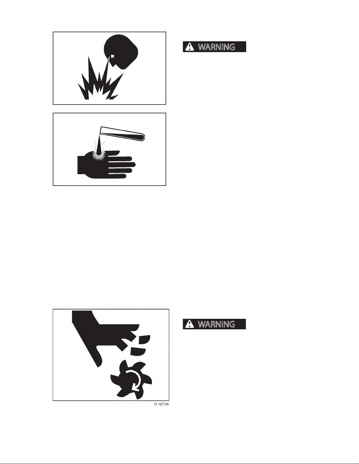
BATTERY SAFETY
sive gases.
Keep sparks, ames, and cigarettes away from batteries. Ventilate properly when charging or using
batteries in enclosed space. Always shield eyes
with goggles and wear a face shield when working
near batteries. Do not lean over batteries during
G.019.02
this operation. Always connect positive (+) to positive (+) and negative (-) to negative (-). For further
instructions, see Jump Starting Battery in Section
6, Operation. If battery acid contacts eyes, ush
them with water for 15 minutes and seek immediate medical attention.
Battery acid is poisonous and can cause severe
burns. If acid is taken internally, call a physician
immediately. If acid contacts skin or clothing, ush
with water immediately. Keep batteries away from
children.
Batteries produce explo-
G.013.02
Battery posts, terminals, and related accessories
contain lead and lead components, chemicals
known to the State of California to cause cancer
and reproductive harm. Wash hands after handling.
Never charge a battery or jump start engine if battery is frozen. Warm battery to 60°F (16°C) or it may
explode. Be sure vent caps are tight. When jump
starting from another machine, be sure machines
do not touch. This machine has a 12-volt starting
system. Use equal voltage for jump starting.
COOLING FAN
Rotating fan can cause severe personal injury or death. Cooling fan can start
at any time, even with the motor o. Keep away
from cooling fan at all times.
2546/2548 T3 1108
12
Page 13
GENERAL SAFETY
WARNING
DANGER
DISCHARGE ACCUMULATOR
pressure can penetrate skin and cause severe
personal injury or death. Charged accumulator can
cause unexpected movement of functions with
engine o.
DO NOT disconnect hoses or ttings, or attempt to service the hydraulic accumulator or pilot circuit without
rst discharging the accumulator.
If ANY uid is injected into the skin, seek
medical attention immediately. A serious
G.002.02
infection or reaction can result without proper medical
treatment.
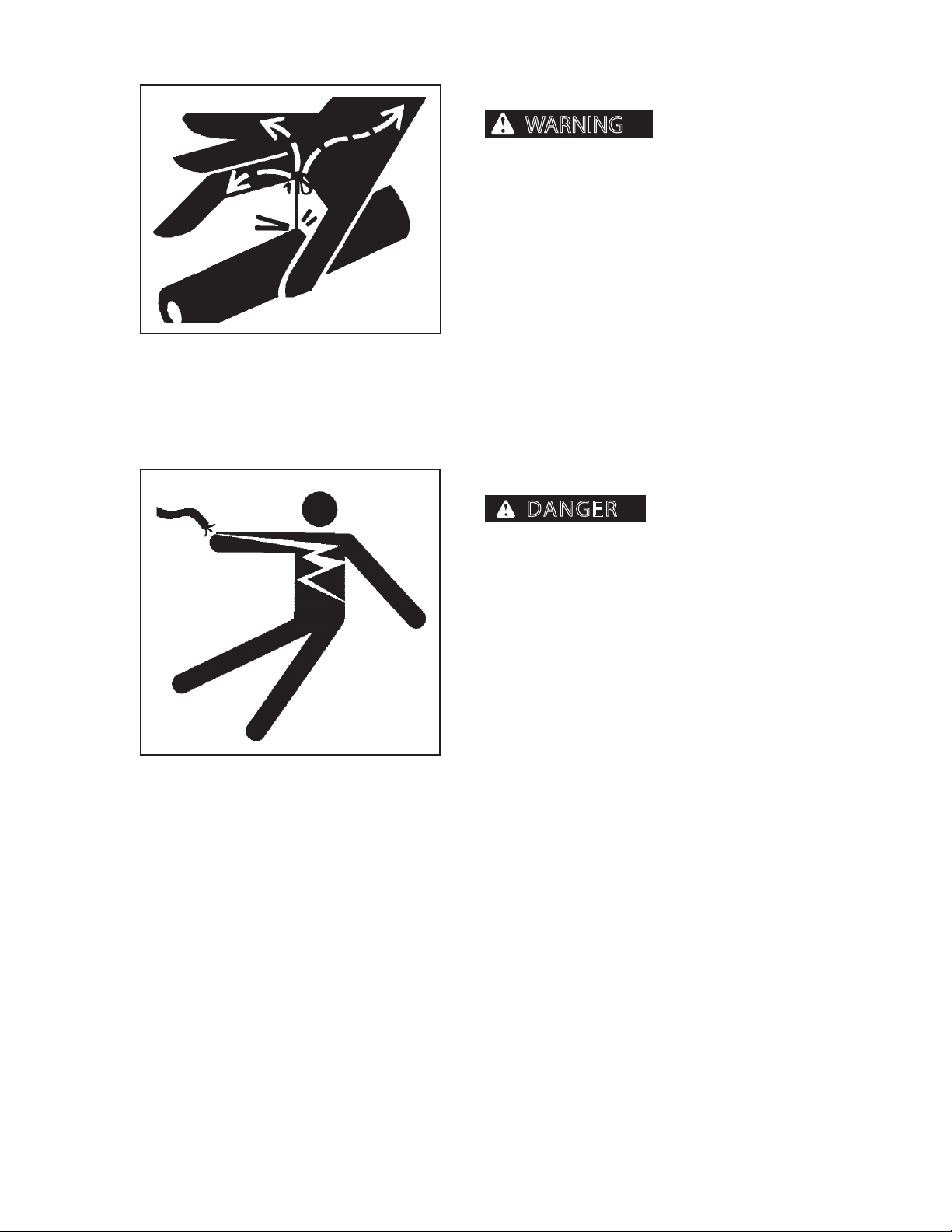
ELECTRIC LINES
Fluids escaping under
G.003.02
SERIOUS INJURY OR
DEATH WILL RESULT FROM CONTACT WITH ELEC
TRIC LINES.
Never move any part of machine or load closer
than 10 feet plus twice the line insulator length to
electric lines. A line insulator is what connects an
electric line to an electric pole.
For example, if a line insulator is 6 inches long,
operator must stay at least 10 feet plus 2x the line
insulator length (2x6 =12 inches or 1 foot from
electric line, which means you must stay at least
11 feet from the electric line).
If machine touches an electric line, stay inside the
cab. Carefully move machine or load away from
electric line, without pulling the line down.
DO NOT let anyone else touch machine while it
is touching an electric line. If it is not possible
to move the machine away from the electric line
without pulling line down, have someone contact
the utility company to disconnect power from line.
If this is not possible, or if machine begins to burn,
jump away from machine to the ground with both
feet together, in one smooth jump. Do not run or
walk away from machine. Jump with feet together
“bunny hop” away from machine. DO NOT touch
machine and ground at the same time or else
electricity in the line will go through your body. Get
away from machine after jumping.
2546/2548 T3 1108
Notify the utility company immediately. DO NOT
let anyone near machine while it is touching an
electric line.
13
Page 14
GENERAL SAFETY
WARNING
WARNING
ELECTRICAL STORM
ning) can cause severe personal injury or death.
When lightning is striking in the vicinity of the
machine, the operator should NEVER attempt the
following procedures:
Mount the machine
Dismount the machine
If you are in the operator’s station during an electrical
storm, stay in the operator’s station. If you are on the
ground during an electrical storm, stay away from the
vicinity of the machine.
Electrical storms (light-
G.083.03
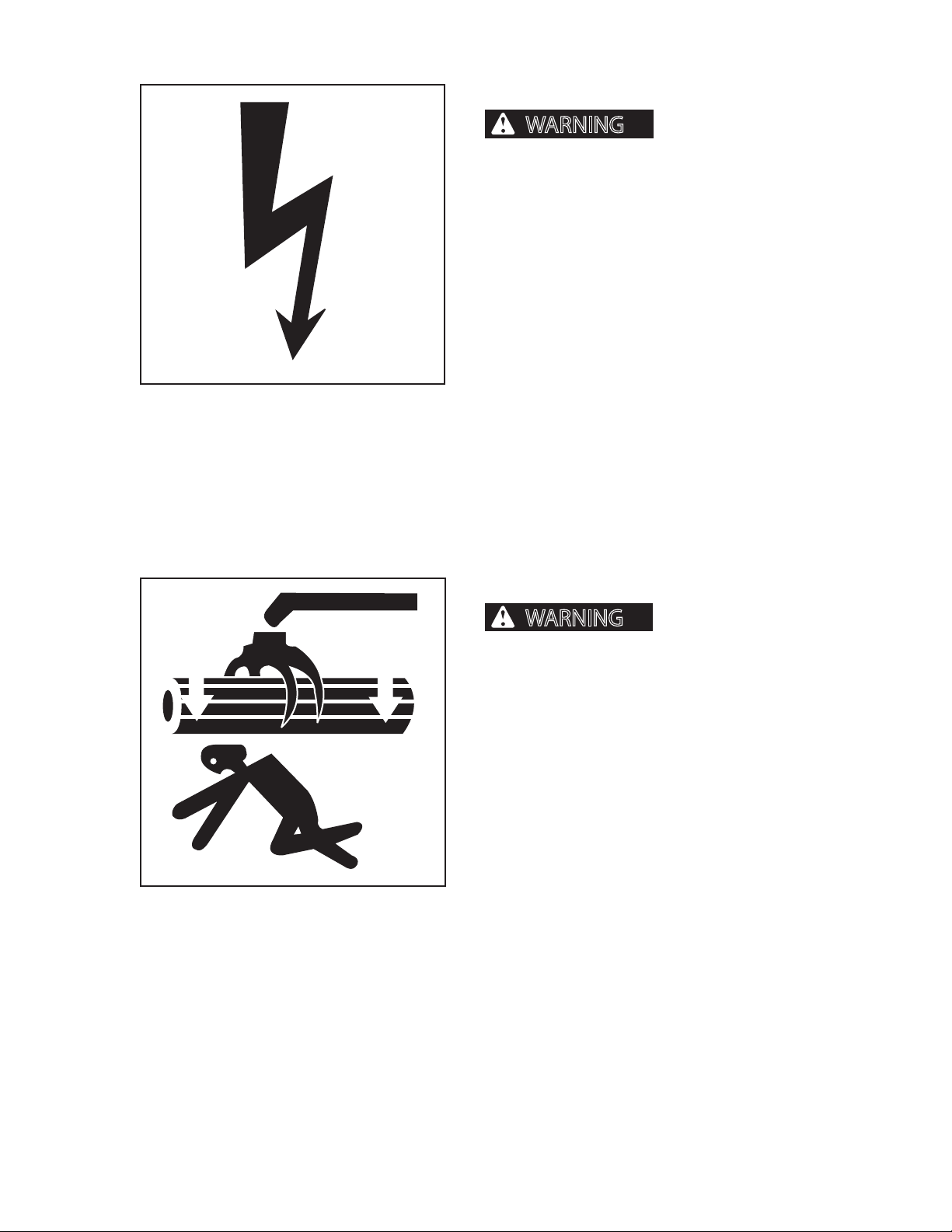
FALLING OR SWINGING LOGS
Falling or swinging logs,
booms, or attachments can cause severe personal
injury or death.
Never operate the boom, attachment or load over or
near personnel.
2546/2548 T3 1108
14
Page 15
GENERAL SAFETY
CAUTION
FIRE PREVENTION/FIRST AID
injury and/or machine damage.
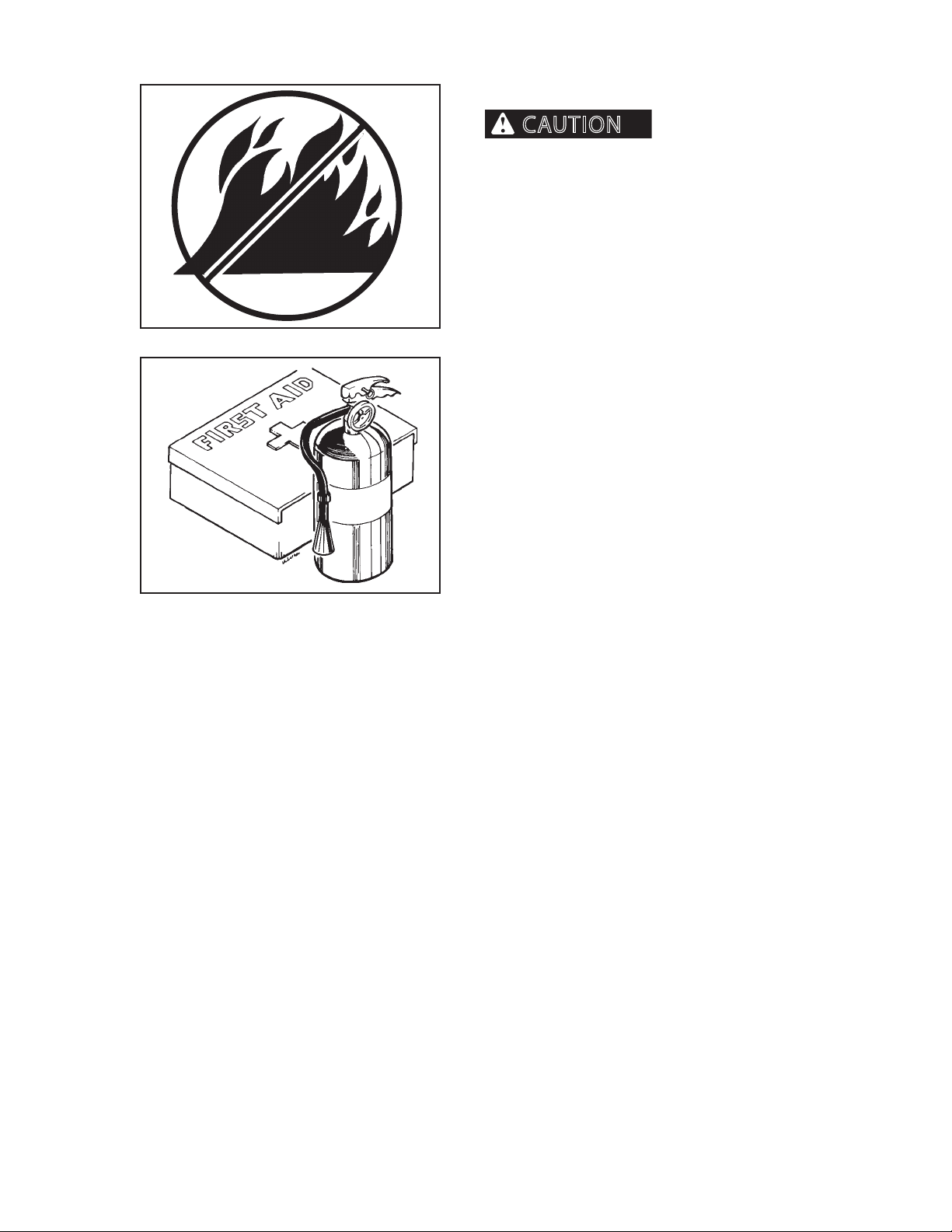
Keep machine clean. Forest debris, rags, and trash will
cause res. Remove all debris, rags, and trash from
machine, especially around engine and hydraulic
components.
Repair all hydraulic and fuel leaks immediately. Do not
operate machine with hydraulic or fuel leaks.
Fire prevention beats re ghting. Remove debris from
G.004.05
all compartments after every eight (8) hours of operation, or more often, if warranted by working conditions.
At the end of each shift ALWAYS stay with the machine
for at least 30 minutes after shutting down the engine
to ensure there is no forest debris/trash re start up.
Keep a re extinguisher ready during this 30 minute
cool down.
Fires can cause personal
G.005.02
Install a rst-aid kit and a re extinguisher in the cab.
Properly maintain rst-aid kit and fully charged re
extinguisher. Follow instructions provided with them.
2546/2548 T3 1108
15
Page 16
GENERAL SAFETY
WARNING
WARNING
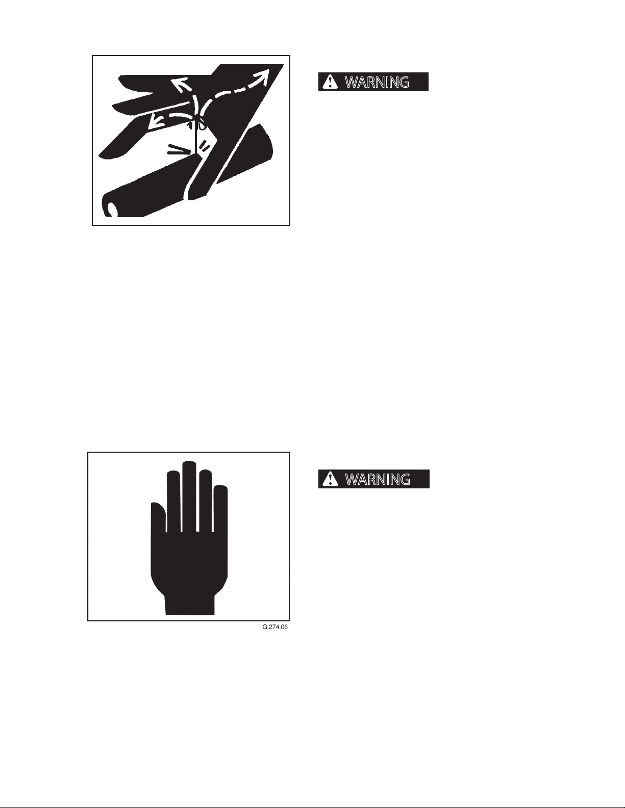
FLUIDS UNDER PRESSURE
pressure can penetrate skin and cause severe personal injury or death.
Wear eye and personal protection equipment
(PPE)!
Always use a board or cardboard when checking oil
hoses, lines, and ttings periodically for leaks, cracks or
defects. Be sure all clamps are in their proper position
and torqued as required and specied. Be sure hoses
are not twisted or touching parts.
Fluids escaping under
G.002.02
DO NOT use hands to search for leaks. Escaping uids
can penetrate skin and enter the bloodstream. Before
disconnecting lines, relieve
all pressure.
DO NOT apply pressure to a damaged line, hose, or
tting.
If ANY uid is injected into the skin, seek
medical attention immediately. A serious
infection or reaction can result without proper medical
treatment.
HAND SIGNALS
Accidents can cause severe personal injury or death.
Know and use hand signals required for particular jobs.
2546/2548 T3 1108
Know who has responsibility for signaling.
16
Page 17
GENERAL SAFETY
WARNING
WARNING
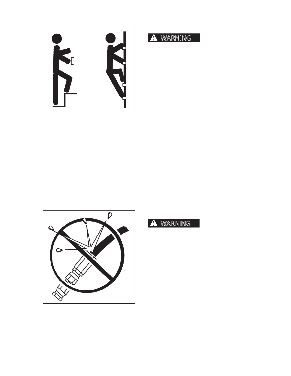
HAND HOLDS AND STEPS
severe personal injury or death.
Use provided hand holds and steps while maintaining at least 3 points of support (1 foot and 2 hands
or 2 feet and 1 hand) when getting on and o machine. Face machine when getting on and
o of it.
Never use controls as hand holds. Never use steering wheel as a hand hold. Moving the steering
wheel from its center position will COMPLETELY
turn machine right or left.
Slips and falls can cause
G.006.02
DO NOT mount machine if hand rails or steps are
broken or missing. Get them repaired rst.
DO NOT jump on or o machine unless it has
touched a live electrical wire and it must be exited.
Ensure rm foot position when getting on and o
machine. Be careful of slippery conditions on platform, steps, and hand holds when getting on and
o machine.
Remove oil, grease, mud, ice, etc. before mounting
or dismounting machine.
To prevent slips and falls, replace skid-resistant material if it is worn, damaged or missing.
HOSES AND FITTINGS
Mismatched brands or
types of hoses and ttings can blow apart and
cause severe personal injury or death.
DO NOT interchange brands or types of hoses
and ttings.
2546/2548 T3 1108
G.007.02
DO NOT install a tting from one manufacturer on a
hose from a dierent manufacturer.
DO NOT install crimp ttings on hoses meant for reusable ttings.
Wear eye and personal protection equipment
(PPE)!
Always use a board or cardboard when checking oil
hoses, lines, and ttings periodically for leaks, cracks or
defects. Be sure all clamps are in their proper position
and torqued as required and specied. Be sure hoses
are not twisted or touching parts.
17
Page 18
GENERAL SAFETY
WARNING
DANGER
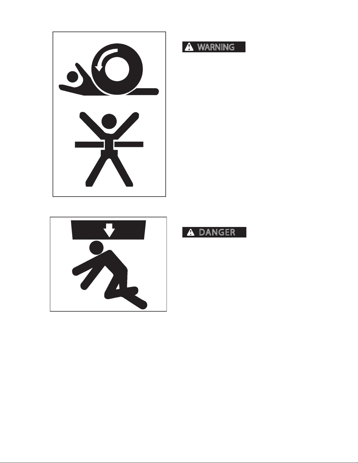
NO RIDERS ON MACHINE
from machine or be injured by movement of machinery, causing severe personal injury or death.
Do not allow riders on any machine that is operating
or moving.
Machine riders can fall
G.009.02
MECHANICAL CAB TILT LOCK
Falling cab can result in
severe personal injury or death.
To reduce the risk of severe personal injury resulting
from a falling cab, always make sure that the mechanical lock is in locked position before reaching under
tilted cab.
See Operation Section in this manual for instructions
on properly installing mechanical cab tilt lock.
2546/2548 T3 1108
18
Page 19
GENERAL SAFETY
WARNING
OPERATOR SAFETY
and/or other material can cause severe personal
injury or death.
When operating machine:
G.010.02
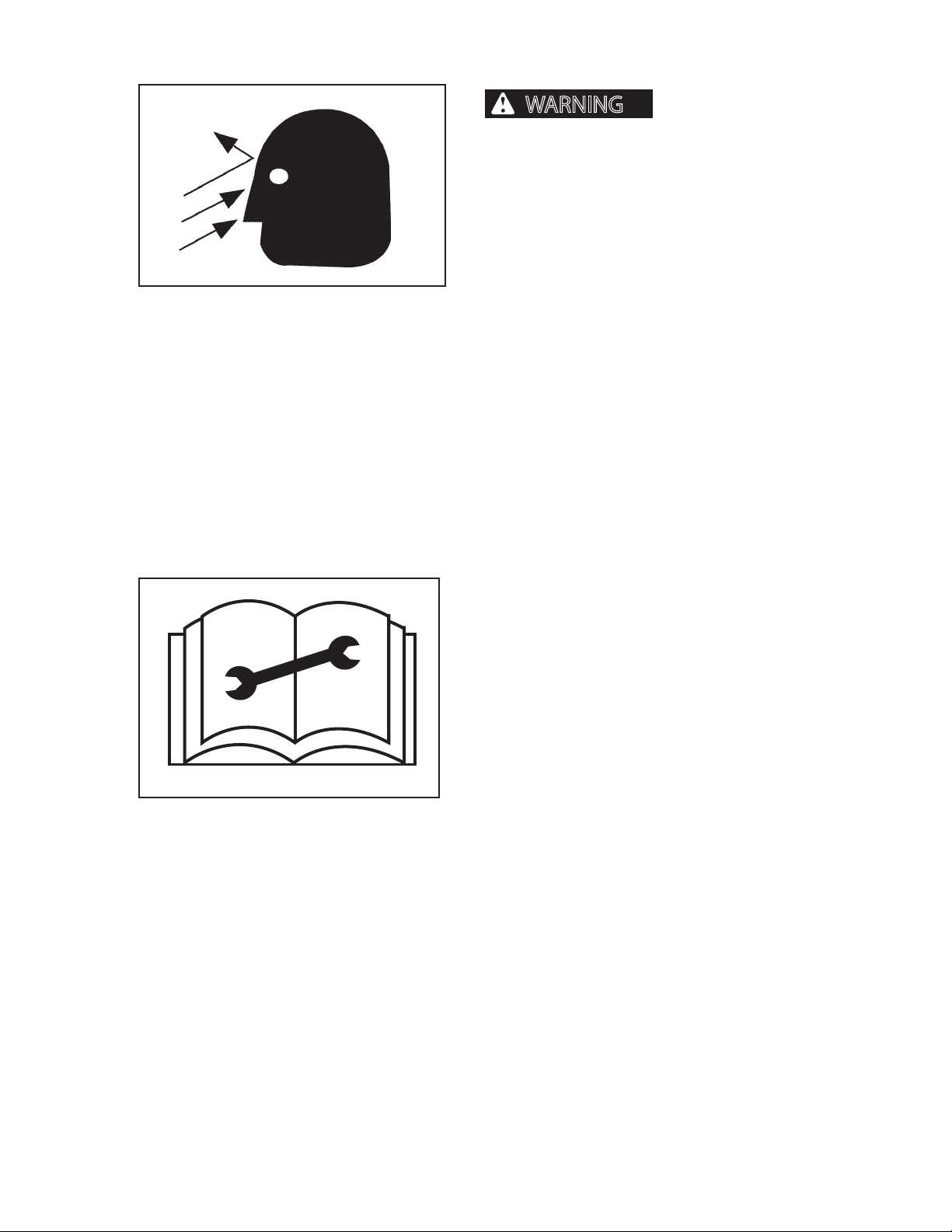
Polycarbonate windows MUST be replaced if damaged. For details, refer to Scheduled/Periodic Maintenance Service.
Flying debris, tree limbs,
1. Keep cab door closed.
2. Polycarbonate window material and/or cab
guarding MUST be in place.
3. All cab openings (front, side, and rear) MUST
be covered with Polycarbonate window material (no glass) and/or protective screen.
4. Window guarding MUST be locked
in place.
104.05
PRACTICE SAFE MAINTENANCE
Read service and maintenance manuals and understand service procedures before performing service/
maintenance.
Understand service procedures before performing
maintenance. When performing maintenance, keep
area around machine clean and dry.
DO NOT service machine while it is moving. Keep away
from power-driven parts. Lower attachment to the
ground. Disengage power. Shut engine down. Move
controls in all directions to relieve hydraulic pressure.
Remove key from ignition. Allow machine to cool
down.
Support all raised equipment.
Keep all machine parts in good condition, and be sure
parts are properly installed. Repair damage immediately. Repair all hydraulic and fuel leaks immediately.
Replace worn or broken parts. Remove any buildup of
grease, oil, or debris.
Disconnect battery ground cable (-) before adjusting
the electrical system.
2546/2548 T3 1108
Lower stabilizers (if so equiped) to the ground. Do not
support machine weight on stabilizers.
19
Page 20
GENERAL SAFETY
WARNING
WARNING
PINCH POINTS
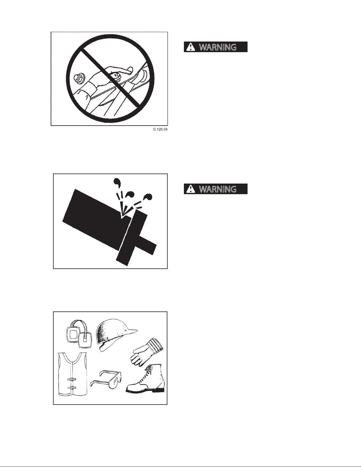
tion of the body where forwarder moves can cause
severe personal injury or death. NEVER place hands
or any portion of the body where injury could occur
if delimber moves. NEVER check pin hole alignments with ngers.
PRESSURE SETTINGS
Placing hands or any por-
G.012.02
Excessive hydraulic pressure can cause component or structural failure,
which may result in severe personal injury or
death.
DO NOT exceed factory-adjusted pressure settings.
PROTECTIVE CLOTHING
Wear OSHA or local regulatory body approved protective clothing when working on or near this machine,
such as
• ear protection • hard hat
• gloves • orange vest
• goggles • steel-toed shoes
2546/2548 T3 1108
G.051.02
Wear snug, protective clothing that is belted where
required.
Remove jewelry before working on or near this machine.
110
Page 21
GENERAL SAFETY
WARNING
CAUTION
WARNING
PROTECTIVE DEVICES/EQUIPMENT
ignorance of protective equipment or devices can
cause severe personal injury or death.
Alarms, re prevention equipment, ROPS/FOPS/OPS,
and other safety equipment is installed on machine for
your protection.
Never ignore, disconnect, disable or modify protection
equipment in any manner.
RADIATOR CAP
Misuse, interference and
G.014.02
Pressurized cooling system
can cause scalding burns.
Allow system to cool. Wear gloves. Remove cap slowly.
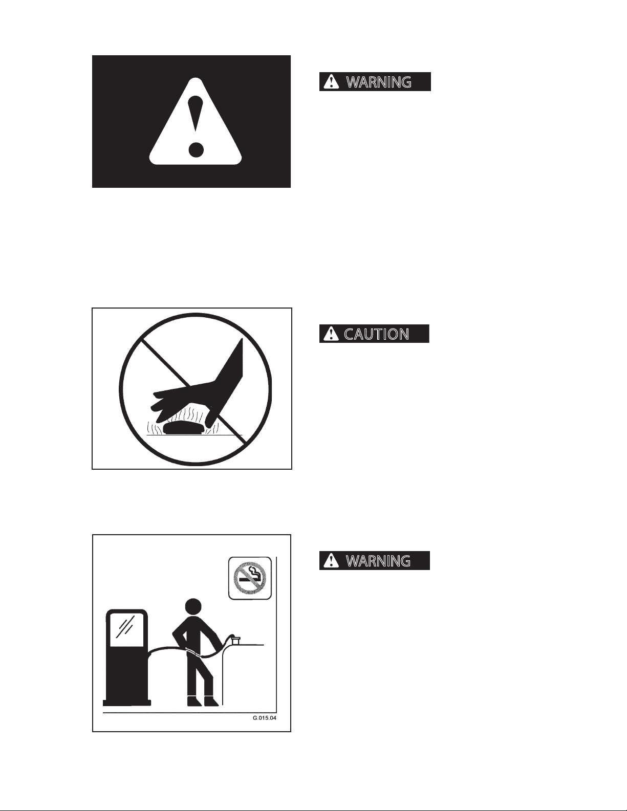
REFUELING
Fires and explosions can
cause severe personal injury or death.
Handle fuel with care. It is highly ammable.
DO NOT refuel machine while smoking or when near
open ame or sparks.
2546/2548 T3 1108
Always stop engine before refueling. Fill fuel tank outdoors. Prevent res by keeping machine clean of trash,
grease, and debris. Always clean up spilled fuel.
G.015.02
111
Page 22
GENERAL SAFETY
WARNING
WARNING
WARNING
ROPS/FOPS/OPS CAB STRUCTURE
structure can cause severe personal injury or
death.
If ROPS/FOPS/OPS structure is damaged (bent or
cracked), it should be inspected by your Hydro-Ax
dealer or by a factory representative. Replace ROPS/
FOPS/OPS structure if it fails inspection. Do not alter
ROPS/FOPS/OPS structure.
G.016.02
SERVICING CONTROL VALVES, CYLINDERS, PUMPS
AND MOTORS
Altering ROPS/FOPS/OPS
settings could cause delimber or component failure
resulting in severe personal injury or death. Do not
change pressure settings. Do not switch lines from
one valve to another.
Special tools and training are required to service control valves, cylinders, pumps and motors. If these parts
need service, see an authorized dealer.
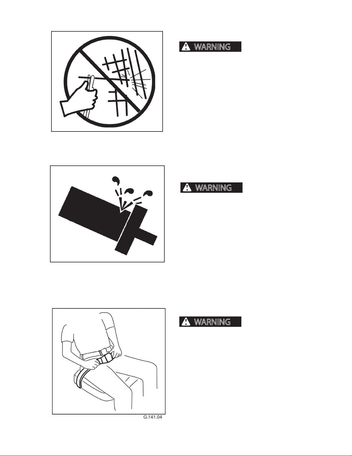
SEAT BELT
can cause severe personal injury or death.
To reduce risk of personal injury resulting from a roll
over or sudden stop, always wear a seat belt fastened
snugly when operating machine.
Increasing relief valve
A roll over or sudden stop
2546/2548 T3 1108
This machine can change directions rapidly. It can
start and stop quickly. See Section 6, Operation, in this
manual for instructions on properly using your seat
belt.
112
Page 23
GENERAL SAFETY
WARNING
WARNING
WARNING
SERVICING MACHINE WITH ENGINE RUNNING
engine running can cause severe injury or death.
Shut down engine and relieve hydraulic pressures
before servicing unless procedure requires engine
running. When maintenance procedure requires
05
engine running, ONLY qualied service technicians
should service machine.
CHECKING ENGINE
• Lower attachment to ground.
• Block (chock) tires.
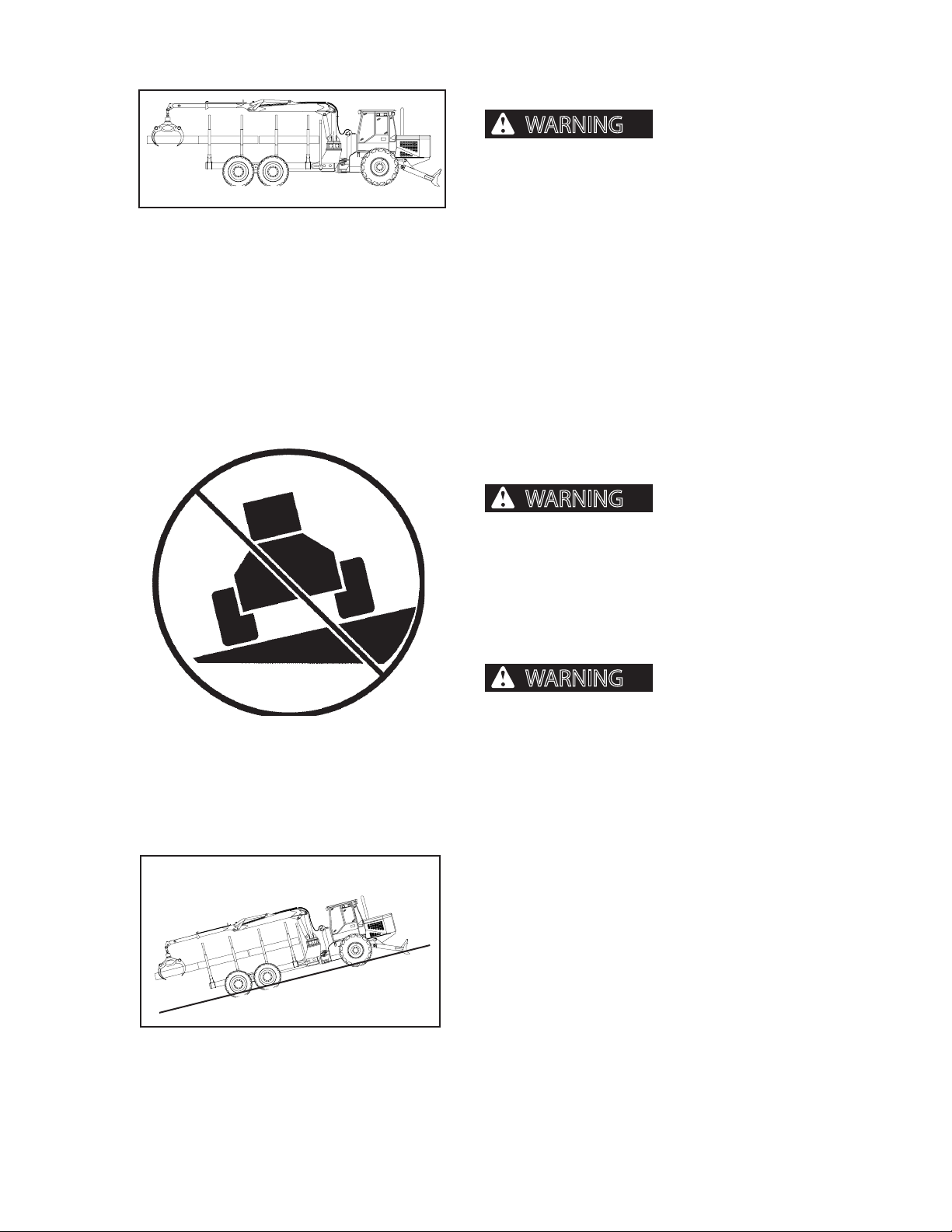
SLOPE OPERATION
Servicing machine with
Operation across a slope
can cause machine to tip over resulting in severe
personal injury or death.
ALWAYS wear seat belt snugly fastened.
DO NOT operate with tires sideways to a slope.
On all slopes, only operate with machine pointed up or
down the slope.
Loss of traction on a steep
slope can cause operator to lose control of tractor
and roll over, resulting in severe personal injury or
death.
ALWAYS wear seat belt, snugly fastened.
DO NOT operate machine on slopes exceeding 30
percent (16.7° angle from horizon). A 30% slope can be
visualized by a three (3) foot rise in a 10 foot distance.
2546/2548 T3 1108
3 feet
10 feet
G.050.02
113
Page 24
GENERAL SAFETY
WARNING
NOTICE
WARNING
DANGER
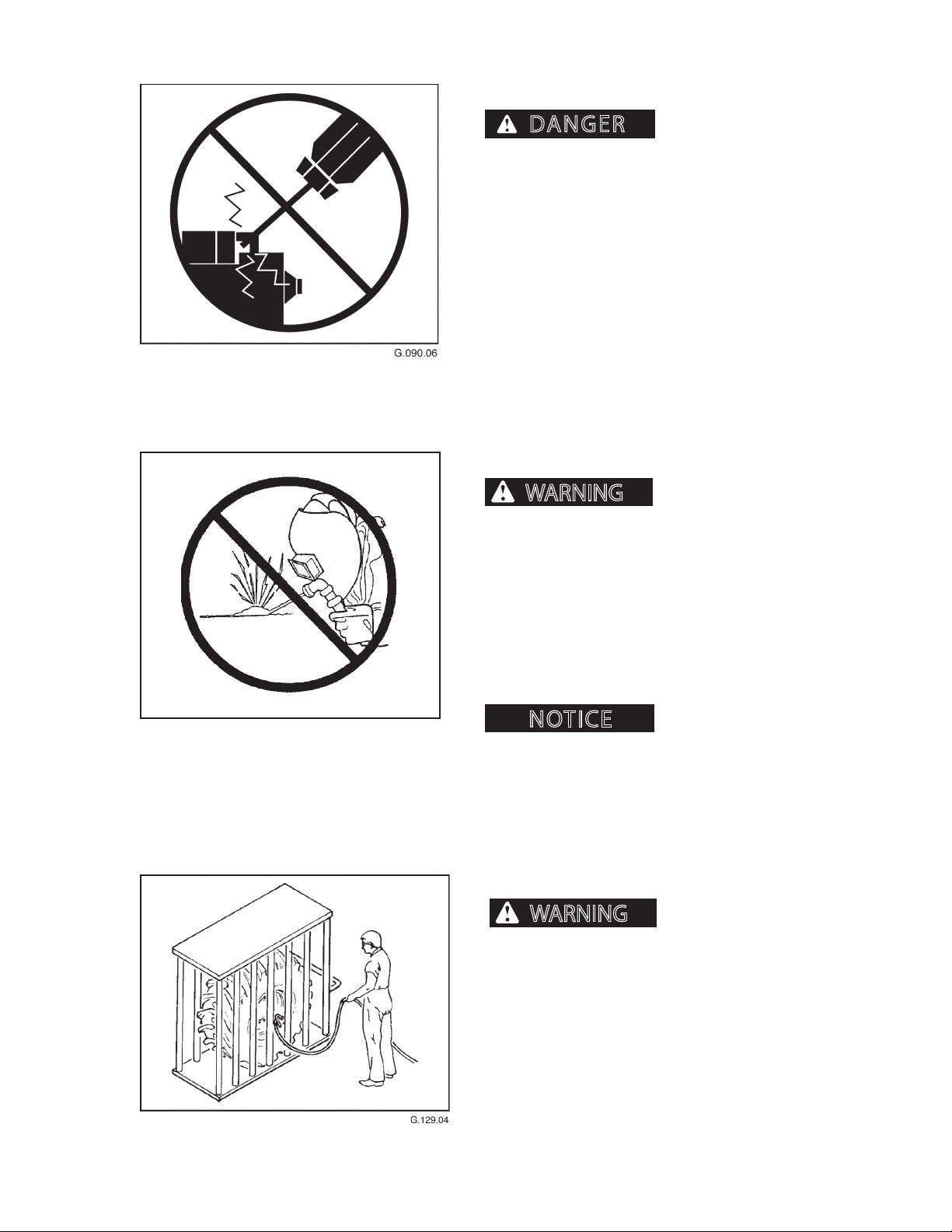
STARTER CIRCUITRY
GEAR IF START CIRCUITRY IS BYPASSED.
Do not attempt to start machine engine by shorting
starter circuit across starter terminals. Doing so may
cause unintended machine movement which could
result in severe personal injury or death and serious
machine and/or property damage.
UNAUTHORIZED WELDING
MACHINE WILL START IN
G.020.02
Unauthorized welding
can cause structural failure and/or severe personal
injury or death.
DO NOT weld on any structural member.
Any unauthorized welding or repair will void
the Warranty.
Once authorized, turn battery disconnect switch OFF
and place welding ground (stinger) as close to the
weld site as possible. Do not allow weld current to pass
through bearings or pivot points.
Welding can cause damage
to the electrical system.
TIRE SAFETY
A tire explosion can cause
severe personal injury or death. DO NOT attempt
to mount a tire without the proper equipment and
experience to do the job.
2546/2548 T3 1108
Have tires mounted by an authorized dealer or by a
qualied repair service.
Maintain proper tire pressure. DO NOT inate tires
above recommended pressure.
114
Page 25
GENERAL SAFETY
WARNING
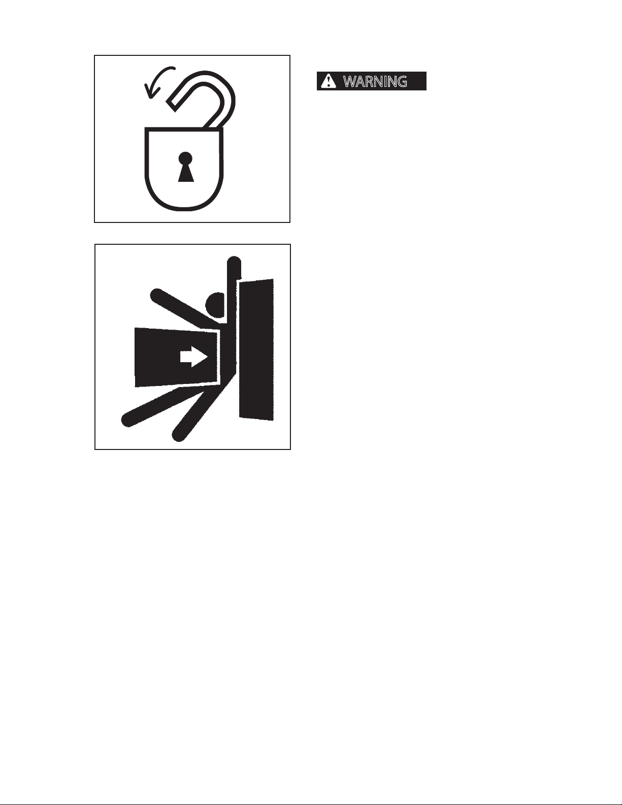
USE STEERING FRAME LOCK
with a person in center hinge crush point area,
severe personal injury or death could occur.
Activating joystick could COMPLETELY turn machine
right or left.
Do not use joystick as a handhold when mounting or
dismounting machine.
NEVER stand in this area with engine running.
Install steering lock BEFORE performing service or
101.05
maintenance.
If steering is activated
G.021.02
2546/2548 T3 1108
115
Page 26

GENERAL SAFETY
2546/2548 T3 1108
116
Page 27
SAFETY DECALS
NOTICE
CAUTION
PRESSURIZED COOLING
SYSTEM.
CAN CAUSE SCALDING
BURNS.
ALLOW SYSTEM TO COOL.
REMOVE CAP SLOWLY
WITH GLOVES ON.
10063918 6/03
CRUSH ZONE
ALWAYS TILT CAB TO FULLY TILTED
ANGLE AND PLACE THE MECHANICAL
LOCK IN THE LOCKED POSITION
BEFORE REACHING UNDER THE CAB.
DANGER
10063337 11/02
WARNING
FLUID ESCAPING UNDER PRESSURE
CAN PENETRATE SKIN AND CAUSE
SEVERE PERSONAL INJURY.
DO NOT DISCONNECT HOSES OR FITTINGS,
OR ATTEMPT SERVICING THE HYDRAULIC
ACCUMULATOR OR PILOT CIRCUIT
WITHOUT FIRST DISCHARGING THE
ACCUMULATOR.
10055037REV A11-97
10062494 02/02
WARNING
ROTATING FAN AND
EXPOSED BELTS CAN
CAUSE SEVERE
PERSONAL INJURY.
KEEP HANDS AWAY AT
ALL TIMES.
10053766
0297
WARNING
ROTATING FAN CAN CAUSE
SEVERE PERSONAL INJURY.
CONDENSER FAN CAN START
AT ANY TIME, EVEN WITH THE
ENGINE OFF.
KEEP HANDS AWAY FROM FAN
AT ALL TIMES.
CAUTION
TURN OFF MASTER
DISCONNECT BEFORE
ANY WELDING
10051827 6/97A
IF EXPOSED SHAFT IS TURNING
WITH PERSON IN IMMEDIATE AREA,
SEVERE INJURY COULD OCCUR.
KEEP CLEAR
NEVER STAND IN THIS AREA WITH
ENGINE RUNNING.
DA N G E R
10063925 7/03
WARNING
RIDING ON MACH INE
OR ATT ACHMENT
CAN CA USE SEVE RE
INJURY OR DEAT H
• NO R IDERS AL LOWED.
17486 1/03
WARNING
DO NOT FILL FUEL FILTERS BEFORE
INSTALLING NEW FUEL FILTERS.
FUEL SYSTEM DAMAGE CAN OCCUR.
10504971 Rev. 1 0608
ELECTRIC PUMP WILL
AUTOMATICALLY FILL FUEL FILTER.
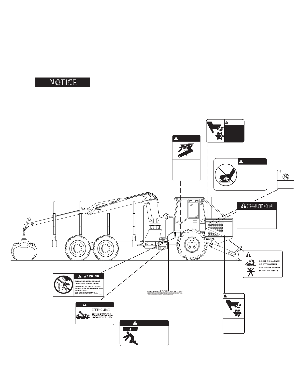
SAFETY DECALS
The following safety decals are located in positions on the machine as continual reminders of HAZARDS. Serious
injury or property damage can occur if safety instructions are not followed.
Keep all safety decals clean and readable. Use a soft cloth, water, and soap to clean decals if they are too dirty to
read. DO NOT clean safety decals with solvent. Solvent can damage them.
Replace safety decals immediately if they are damaged, missing, or hard to read. Contact an authorized dealer
for replacement safety decals. Your authorized dealer will provide free replacement safety decals if you provide a
valid serial number for your machine.
If you replace a part that has safety decal, apply a new safety decal to the replacement
part. Before putting a new decal on the machine or part, be sure the surface where decal will be mounted is clean and
dry.
2546/2548 T3
located on both sides of machine
21
located on both sides of machine
located on both sides of machine
1108
Page 28
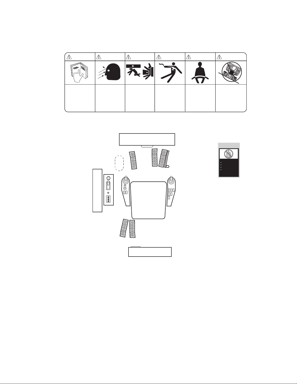
Located on header
CAUTION
CHECK DAILY FOR
DEBRIS
LEAKS
DAMAGED WIRES/HOSES
WORKING FIRE
FIGHTING DEVICES
Presented by T.E.A.M.
Working Group
10063809 4/03 Rev A
WARNING
UNSAFE OPERATION O R
MAINTEN ANCE CAN CA USE
SEVERE INJURY OR D EATH.
DO NOT O PERATE OR W ORK
ON THIS MACHINE WIT HOUT
READING & UNDERSTAN DING
THE OPER ATOR'S MANU AL.
FALLING ATTACHMENT OR
UNINTEN DED TRACTOR
MOVEMEN T CAN CAUSE SEVERE
INJURY OR DEATH.
DEBRIS COMING THRO UGH CAB
OPENING S CAN CAUSE SEVERE
INJURY OR DEATH
CONTACT ING ELECTRI C LINES
WITH LI FT ARM, ATT ACHMENT,
OR LOAD CAN CAUSE SEVERE
INJURY OR DEATH.
UNLAWFUL TO OPERATE THIS
MACHINE, LIFT ARM, ATTACHMENT,
OR LOAD WITHIN 10 F EET, PLUS
2 TIMES LINE INSULA TOR LENGTH,
OF ANY E LECTRIC LIN E.
WHILE OP ERATING MAC HINE:
.
KEEP BO TH CAB DOOR S CLOSED.
.
ALL CAB OPENINGS ( FRONT, SIDE
AND RE AR) MUST BE COVERED
WITH TUFFEX@ WINDOW
MATERI AL (NO GLAS S) AND/OR
PROTEC TIVE SCREEN .
BEFORE DISMOUNTING FROM MACHINE:
.
MOVE THE MACHINE TO LEVEL GROUND.
.
LOWER ATTACHMENT TO THE GROUND.
.
SET PARKING BRAKE.
.
SHUT OFF MACHINE.
.
RELIEVE HYDRAULIC PRESSURE.
.
REMOVE KEY FROM STARTER SWITCH.
WARNING WARNING WARNING WARNING WARNING
100 63 923 6/ 03 Rev B 7/ 05
FAILURE TO WEAR SEAT BELT
CAN CAUSE SEVERE
PERSONAL INJURY OR DEATH.
ALWAYS WEAR SEAT BELT
(ADJUSTED UNTIL SNUG) WHILE
OPERATING THIS MACHINE.
OPERATION ACROSS A SLOPE
COULD CAUSE THE MACHINE
TO OVERTURN AND CAUSE
SEVERE INJURY OR DEATH.
DO NOT OPERATE WITH TIRES
SIDEWAYS TO SLOPE.
ON ALL SLOPES OPERATE WITH
TIRES POINTED UP AND DOWN
THE SLOPE.
SAFETY DECALS
Located on entry door
2546/2548 T3
22
1108
Page 29
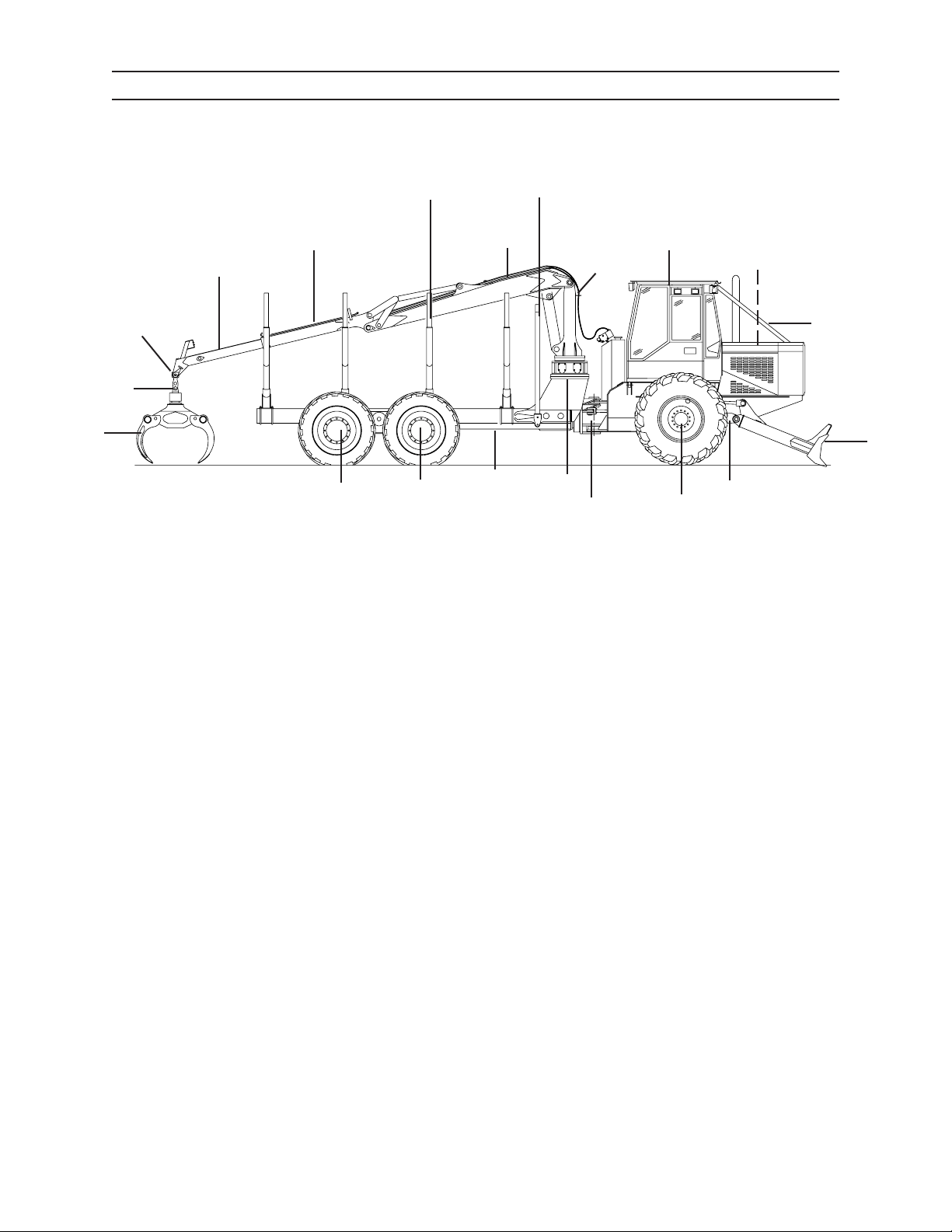
COMPONENT TERMINOLOGY
COMPONENT TERMINOLOGY
FORWARDER
18
5
6
7
17
4
3
2
10
19
8
9
1. Blade
2. Cab
16
16
15
14
13
11. Front Frame
12. Single Axle & Wheels
12
11
1
3. Loader Mast
4. Main Boom
5. Stick Boom
6. Extension Boom (optional)
7. Grapple Dampener Link
8. Grapple Rotator
9. Grapple
10. Engine Compartment
13. Steering Knuckle
14. Mast Swing Box Assembly
15. Rear Frame
16. Dual - Bogie Axle and Wheels
17. Barrier
18. Bunk Tubes
19. Limb Risers
2546/2548 T3
31
1108
Page 30

COMPONENT TERMINOLOGY
NOTES
2546/2548 T3
32
1108
Page 31
IQAN®
F1 F2 F3
UP
DN
ESC
Pressure
PSI
RPM
RPM
1
IQAN
®
INTRODUCTION
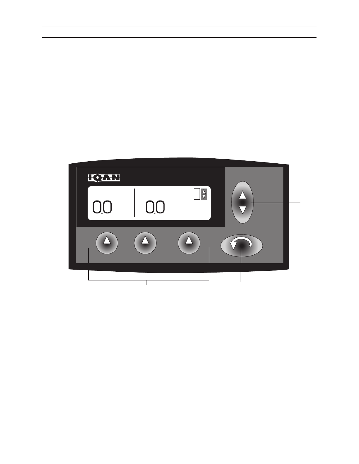
The IQAN® system is a computer-based control system that delivers precision control through the valving system.
IQAN®’s menus control machine function and aid in troubleshooting.
IQAN® MDM DISPLAY
The IQAN® terminal displays information for machine instrumentation and consists of an MDM screen and ve
function buttons. With this display, the operator monitors machine functions such as engine rpm, oil temperature, hydraulic pressure, and other operator-specic selections. IQAN® also displays alarm signals.
To operate the IQAN® system, ignition switch must be turned to ACC or RUN.
1. Up and down key
2. F1-F3 keys
3. Escape key
The IQAN® system has ve sub menus which can be accessed by depressing the ESC key:
Sub Menus:
Mode
Information
Settings
2
3
MAIN SCREEN - This screen appears after machine start up.
1
IQAN44
Measure
Properties
2546/2548 T3
41
1108
Page 32
IQAN®
F1 F2 F3
UP
DN
ESC
Pressure
PSI
RPM
RPM
1
F1 F2 F3
UP
DN
ESC
25 May 2005
500 Series LH Boom 03.71
09:45
1
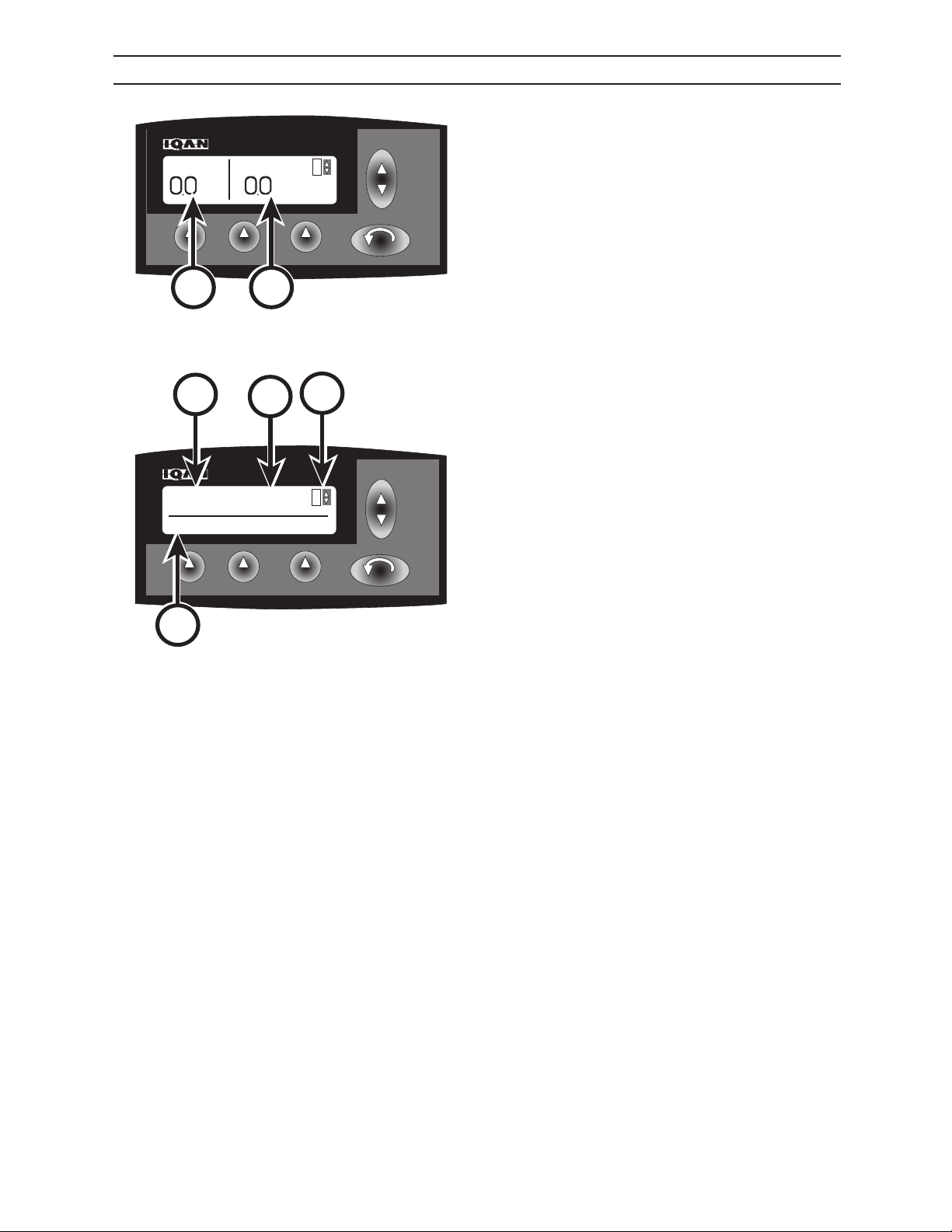
IQAN® MAIN SCREEN
The IQAN® main screen appears after start up of the
machine.
Hydraulic pressure (A) and RPM (B) are displayed on
the main screen start up.
A
C
B
D
E
IQAN.44
Scroll using the up & down key to access time (C), date
(D), user mode (E) and version of program (F).
F
IQAN.45
2546/2548 T3
42
1108
Page 33
IQAN®
F1 F2 F3
UP
DN
LCD LANGUAGE MORE..
ESC
1
SETTINGS
F1 F2 F3
UP
DN
LCD LANGUAGE MORE..
ESC
1
F1 F2 F3
UP
DN
ESC
Pressure
PSI
RPM
RPM
1
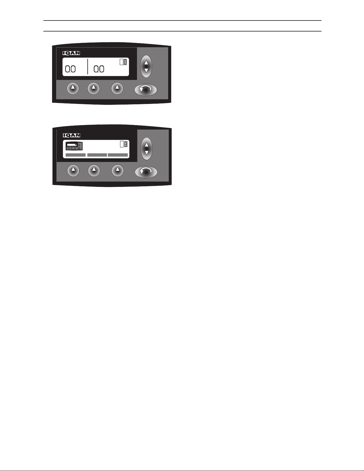
IQAN® SETTINGS SCREEN
Depress the ESC key to access the adjustment menus.
IQAN.44
Scroll using the up & down key until SETTINGS is displayed on the IQAN® screen.
IQAN.4
2546/2548 T3
43
1108
Page 34
IQAN®
F1 F2 F3
UP
DN
CONTRAST LIGHT
ESC
1
LCD SETTINGS
F1 F2 F3
UP
DN
LCD LANGUAGE MORE..
ESC
1
SETTINGS
F1 F2 F3
UP
DN
LCD LANGUAGE MORE..
ESC
1
F1 F2 F3
UP
DN
CONTRAST LIGHT
ESC
1
LCD SETTINGS
F1 F2 F3
UP
DN
OK CANCEL RESET
ESC
1
LCD CONTRAST
25
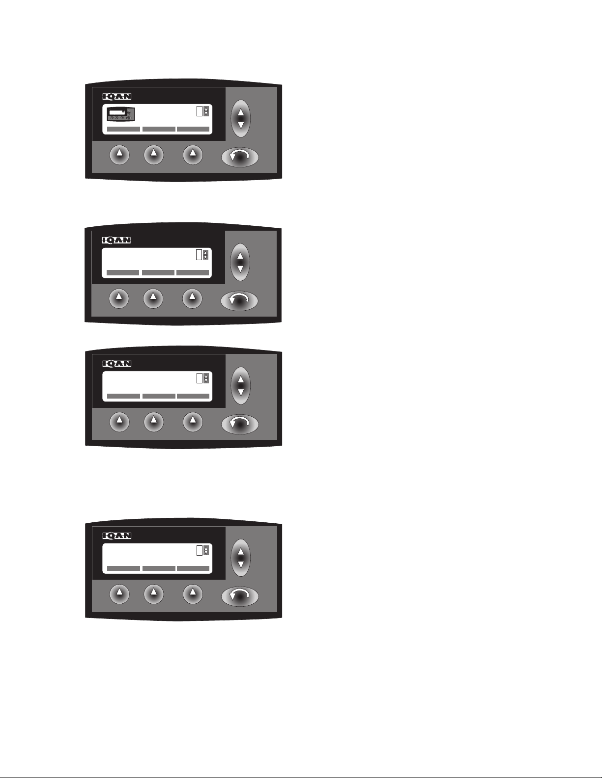
IQAN® LCD/LIGHT SETTINGS SCREEN
Depress F1 key to select LCD setting.
IQAN.4
Depress F1 key to adjust contrast level of screen.
IQAN.20
IQAN.20
IQAN.21
Depress F2 key to adjust light level of screen.
To adjust screen contrast level, scroll using the up &
down key.
Depress F1 key to save changes.
F2 key to cancel changes.
F3 key to restore to factory settings.
Note: Use the same process to adjust light level of
screen.
2546/2548 T3
44
1108
Page 35
IQAN®
F1 F2 F3
UP
DN
LCD LANGUAGE MORE..
ESC
1
SETTINGS
F1 F2 F3
UP
DN
LCD LANGUAGE MORE..
ESC
1
F1 F2 F3
UP
DN
OK CANCEL
ESC
1
ENGLISH
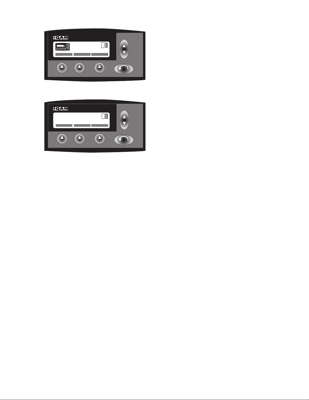
IQAN® LANGUAGE SETTINGS SCREEN
Depress F2 key to select language setting.
IQAN.4
To adjust language, scroll using the up & down key .
Note:
Depress F1 key to save changes.
F2 key to cancel changes.
IQAN.22
2546/2548 T3
45
1108
Page 36
IQAN®
F1 F2 F3
UP
DN
LCD LANGUAGE MORE..
ESC
1
SETTINGS
F1 F2 F3
UP
DN
LCD LANGUAGE MORE..
ESC
1
F1 F2 F3
UP
DN
SOUND SET CLOCK MORE..
ESC
1
SETTINGS
F1 F2 F3
UP
DN
LCD LANGUAGE MORE..
ESC
1
F1 F2 F3
UP
DN
ALARM BUTTON
ESC
1
SOUND SETTING
F1 F2 F3
UP
DN
OK CANCEL RESET
ESC
1
ALARM SOUND
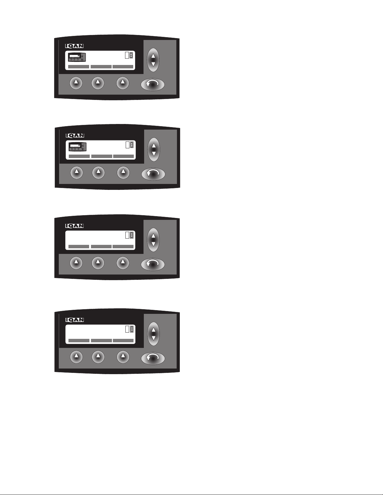
50
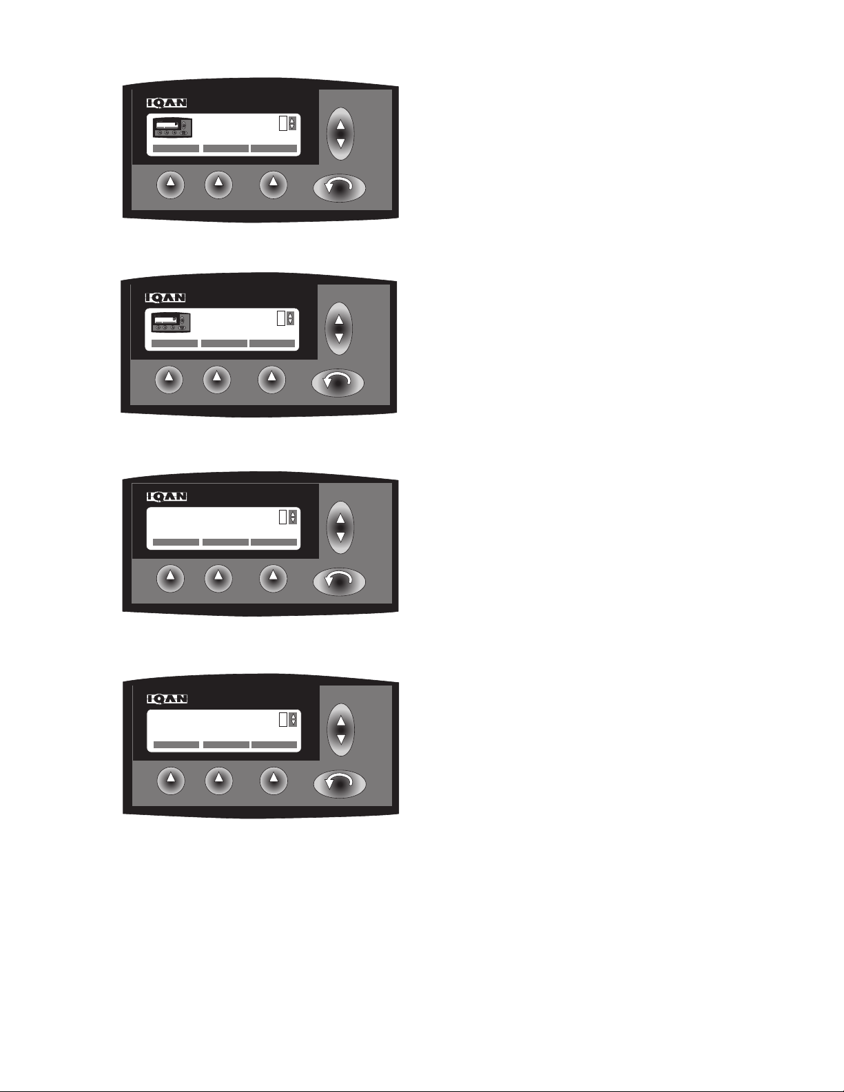
IQAN® ALARM SOUND SETTINGS SCREEN
Depress F3 key to access more setting adjustments.
IQAN.4
Depress F1 key to access sound setting adjustments.
IQAN.43
IQAN.25
IQAN.26
Depress F1 key to change alarm setting volume.
To adjust volume of alarm, scroll using the up & down
key.
Note:
Depress F1 key to save changes.
F2 key to cancel changes.
F3 key to restore to factory settings.
2546/2548 T3
46
1108
Page 37
IQAN®
F1 F2 F3
UP
DN
LCD LANGUAGE MORE..
ESC
1
SETTINGS
F1 F2 F3
UP
DN
LCD LANGUAGE MORE..
ESC
1
F1 F2 F3
UP
DN
SOUND SET CLOCK MORE..
ESC
1
SETTINGS
F1 F2 F3
UP
DN
LCD LANGUAGE MORE..
ESC
1
F1 F2 F3
UP
DN
ALARM BUTTON
ESC
1
BUTTON SETTING
F1 F2 F3
UP
DN
ALARM BUTTON
ESC
1
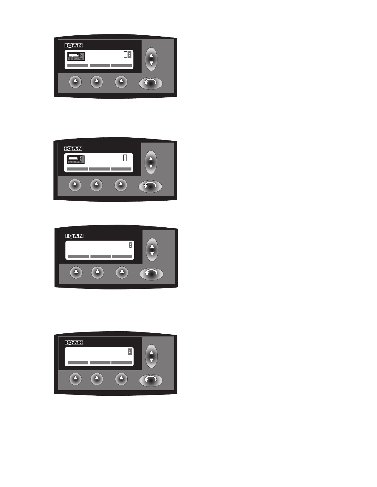
BUTTON SOUND
50
IQAN® BUTTON KEY SOUND SETTINGS SCREEN
Depress F3 key to access more setting adjustments.
IQAN.4
Depress F1 key to access sound setting adjustments.
IQAN.43
IQAN.27
IQAN.28
Depress F2 key to change button setting volume.
To adjust volume of buttons, scroll using the up &
down key.
Note:
Depress F1 key to save changes.
F2 key to cancel changes.
F3 key to restore to factory settings.
2546/2548 T3
47
1108
Page 38
IQAN®
F1 F2 F3
UP
DN
SELECT
ESC
SET YEAR
0
F1 F2 F3
UP
DN
SELECT
ESC
SET MONTH
0
F1 F2 F3
UP
DN
LCD LANGUAGE MORE..
ESC
1
SETTINGS
F1 F2 F3
UP
DN
LCD LANGUAGE MORE..
ESC
1
F1 F2 F3
UP
DN
SOUND SET CLOCK MORE..
ESC
1
SETTINGS
F1 F2 F3
UP
DN
LCD LANGUAGE MORE..
ESC
1
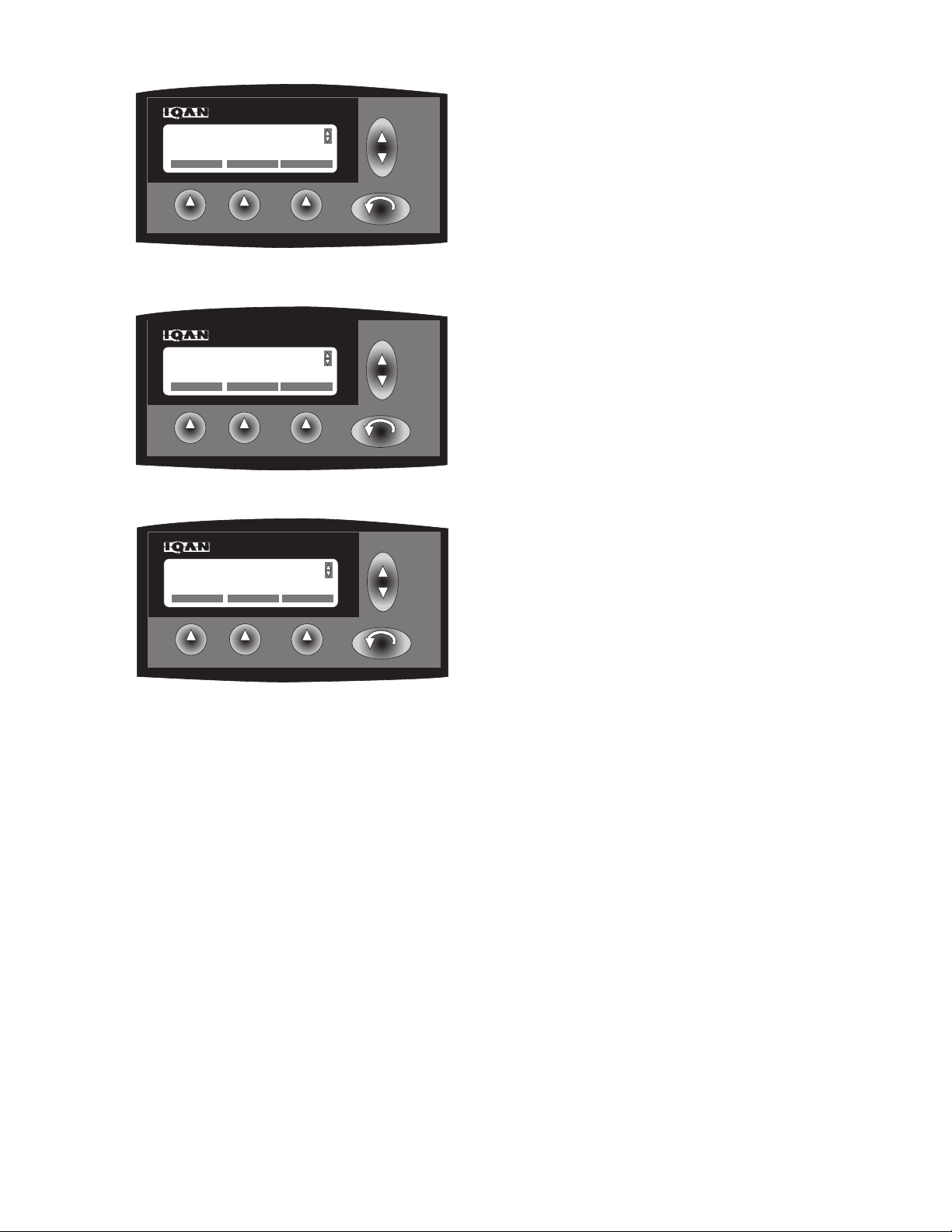
IQAN® DATE/TIME SCREEN
Select more information by depressing the F3 key.
IQAN.4
Depressing the F2 key to set clock.
IQAN.5
IQAN.6
Scroll using the up & down key to display function to
change (example: SET YEAR). Depress the F1 key to
select function to set (example: SET YEAR displayed
on IQAN® screen). Using the up & down key, scroll
through years. Depress the F1 key when desired year is
displayed on the IQAN® screen.
Scroll using the up & down key to display function to
change (example: SET MONTH). Depress the F1 key to
select function to set (example: SET MONTH displayed
on IQAN® screen). Using the up & down key, scroll
through months of the year. Depress the F1 key when
desired month is displayed on the IQAN® screen.
2546/2548 T3
IQAN.7
48
1108
Page 39
IQAN®
F1 F2 F3
UP
DN
SELECT
ESC
SET DAY
0
F1 F2 F3
UP
DN
SELECT
ESC
SET HOUR
0
F1 F2 F3
UP
DN
SELECT
ESC
SET MINUTE
0
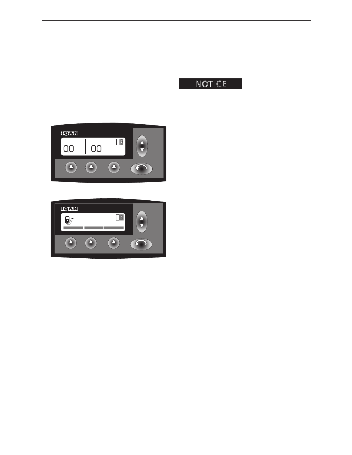
IQAN® DATE/TIME SCREEN
Scroll using the up & down key to display function to
change (example: SET DAY). Depress the F1 key to
select function to set (example: SET DAY displayed
on IQAN® screen). Using the up & down key, scroll
through days of the week. Depress the F1 key when
desired day is displayed on the IQAN® screen.
IQAN.8
Scroll using the up & down key to display function to
change (example: SET HOUR). Depress the F1 key to
select function to set (example: SET HOUR displayed
on IQAN® screen). Using the up & down key, scroll
through hours of the day. Depress the F1 key when
desired hour is displayed on the IQAN® screen.
IQAN.9
IQAN.11
Scroll using the up & down key (E) to display function
to change (example: SET MINUTE). Depress the F1
key (F) to select function to set (example: SET MINUTE
displayed on IQAN® screen). Using the up & down key
(E), scroll through minutes of the hour. Depress the F1
key (F) when desired minute is displayed on the IQAN®
screen.
Note: To cancel changes in any of the above listed settings, depress the F2 key (cancel).
2546/2548 T3
49
1108
Page 40
IQAN®
NOTICE
F1 F2 F3
UP
DN
INPUTS OUTPUTS OTHER
ESC
1
MEASURE
1.01
F1 F2 F3
UP
DN
ESC
Pressure
PSI
RPM
RPM
1
IQAN® MEASURE SCREEN
Measure screen is used to visually monitor the electrical input and output of system components controlled
by the IQAN®. An alarm and/or error message will
appear on IQAN® screen if input or output is outside
parameters required for proper system function.
functions is key to troubleshooting machine.
Depress the ESC key to access the adjustment menus.
Understanding measure
IQAN.1
IQAN.29
Scroll using the up & down key until MEASURE is displayed on the IQAN® screen.
Note: Measureable information includes Votlage inputs (5 volts or less), digital inputs (12 volts), frequency
inputs (hertz), direction inputs (5 volts or less), current
(milliamps), and digital outputs (12 volts).
2546/2548 T3
410
1108
Page 41
F1 F2 F3
UP
DN
MV SCOPE
ESC
VOLTAGE IN
XP-0 C1:2
Left JS YAX18
+88.4%
F1 F2 F3
UP
DN
MV SCOPE
ESC
VOLTAGE IN
XP-0 C1:2
Left JS YAX18
+88.4%
F1 F2 F3
UP
DN
VOLTAGE DIGITAL FREQUENCY
ESC
1
MEASURE INPUTS
NOTICE
B
IQAN®
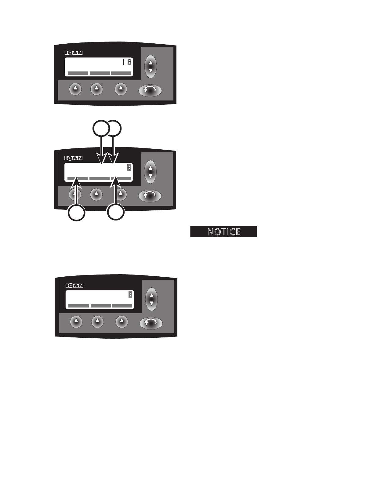
IQAN® VOLTAGE INPUT MEASURE SCREEN
Depress the F1 key to measure inputs.
IQAN.30
C
Scroll using the up & down key to select control
function to measure. Depress the F1 key to measure
control function. IQAN® screen will display:
• control function being measured (A)
• module connected to measured input
control function (B)
A
D
IQAN.31
IQAN.31
• connector and pin number of module (C)
• percent of input to control function (D)
Understanding measure
functions is key to troubleshooting machine.
Depress the F1 key to access measured value in millivolts.
Depress the F3 key to view input in graph format.
Depress ESC key to return to previous screen.
Voltage Inputs (5 volts or less):
Allows operator to measure the status of voltage
coming from the components to the computer. These
components are:
Door switch
2546/2548 T3
Seat load proximity switch
Steer proximity switch
Main boom proximity switch
Swing limit proximity switch
Hydraulic pressure
Switch transmission lter
411
1108
Page 42
F1 F2 F3
UP
DN
MV SCOPE
ESC
DIGITAL IN
XP-0 C1:1
Arming Switch LOW
F1 F2 F3
UP
DN
MV SCOPE
ESC
DIGITAL IN
XP-0 C1:1
Arming Switch LOW
F1 F2 F3
UP
DN
VOLTAGE DIGITAL FREQUENCY
ESC
1
MEASURE INPUTS
NOTICE
B
IQAN®
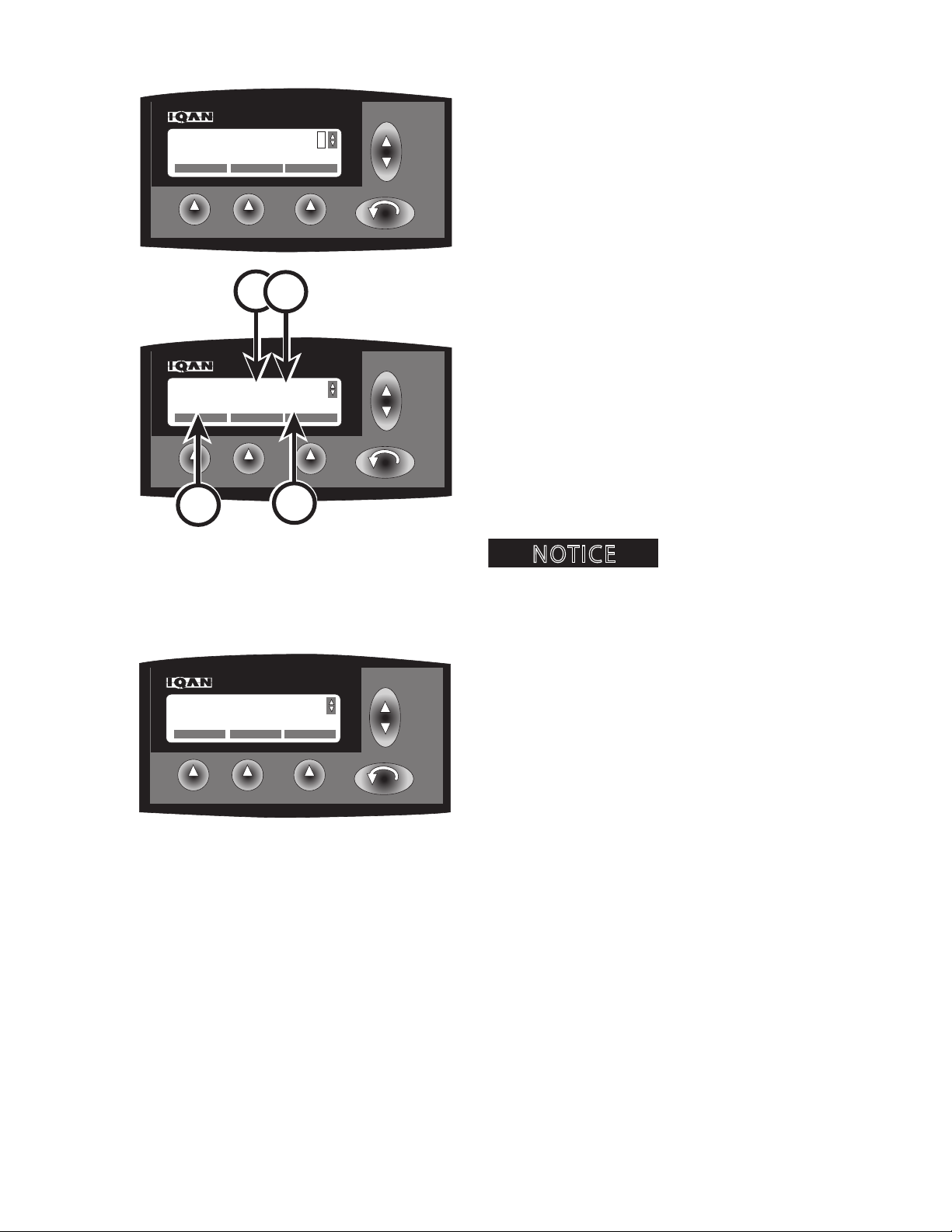
IQAN® DIGITAL INPUT MEASURE SCREEN
Depress the F1 key to measure inputs.
IQAN.30
C
Scroll using the up & down key to select control
function to measure. Depress the F1 key to measure
control function. IQAN® screen will display:
• control function being measured (A)
• module connected to measured input
control function (B)
A
D
IQAN.32
• connector and pin number of module (C)
• percent of input to control function (D)
Understanding measure
functions is key to troubleshooting machine.
Depress the F1 key to access measured value in millivolts.
Depress the F3 key to view input in graph format.
Depress ESC key to return to previous screen.
IQAN.32
Digital Inputs (12 volts):
Allows operator to measure the status of voltage
coming from the components to the computer. These
components are:
Switch hydraulic lter
2546/2548 T3
Switch retract (top of left joystick)
Switch extend (top of left joystick)
Switch grapple open (top of right joystick)
Switch grapple close (top of right joystick)
Switch bogie lift (red button on steer joystick)
412
1108
Page 43
F1 F2 F3
UP
DN
MV SCOPE
ESC
FREQUENCY IN
XP-0 C1:6
Engine Speed
890
RPM
F1 F2 F3
UP
DN
VOLTAGE DIGITAL FREQUENCY
ESC
1
MEASURE INPUTS
F1 F2 F3
UP
DN
MV SCOPE
ESC
FREQUENCY IN
XP-0 C1:6
Engine Speed
890
RPM
NOTICE
B
IQAN®
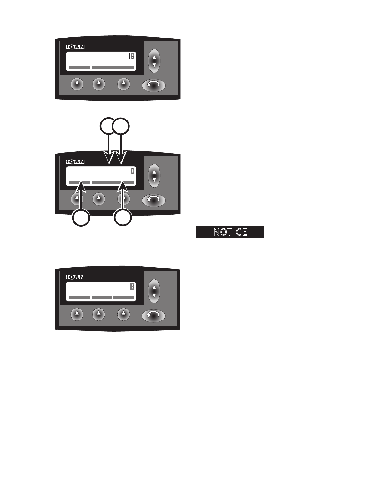
IQAN® FREQUENCY INPUT MEASURE SCREEN
Depress the F1 key to measure inputs.
IQAN.30
C
Scroll using the up & down key to select control
function to measure. Depress the F1 key to measure
control function. IQAN® screen will display:
• control function being measured (A)
• module connected to measured input
control function (B)
A
D
IQAN.33
IQAN.33
• connector and pin number of module (C)
• RPM (D)
Understanding measure
functions is key to troubleshooting machine.
Depress the F1 key to access measured value in hertz
value.
Depress the F3 key to view input in graph format.
Depress ESC key to return to previous screen.
Frequency Inputs (hertz):
Allows operator to measure the status of voltage
coming from the components to the computer. These
components are:
Engine RPM
2546/2548 T3
413
1108
Page 44
F1 F2 F3
UP
DN
SCOPE
ESC
DIRECTION IN
LX-AO X
JS Left E-W
0.0
F1 F2 F3
UP
DN
VOLTAGE DIGITAL FREQUENCY
ESC
1
MEASURE INPUTS
NOTICE
B
F1 F2 F3
UP
DN
SCOPE
ESC
DIRECTION IN
LX-AO X
JS Left E-W
0.0
IQAN®
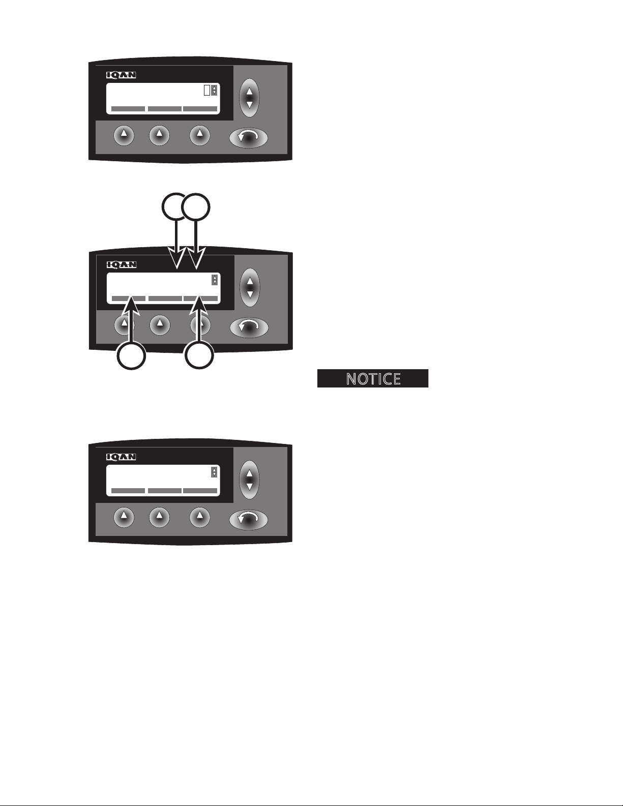
IQAN® DIRECTION INPUT MEASURE SCREEN
Depress the F1 key to measure inputs.
IQAN.30
C
Scroll using the up & down key to select control
function to measure. Depress the F1 key to measure
control function. IQAN® screen will display:
• control function being measured (A)
• module connected to measured input
control function (B)
A
D
IQAN.53
IQAN.53
• connector and pin number of module (C)
• percent of input to control function (D)
Understanding measure
functions is key to troubleshooting machine.
Depress the F3 key to view input in graph format.
Depress ESC key to return to previous screen.
Direction Inputs (5 volts or less):
Allows operator to measure the status of voltage
coming from the components to the computer. These
components are:
Right joystick
North-South (N-S)
East-West (E-W)
2546/2548 T3
Left joystick
North-South (N-S)
East-West (E-W)
Steer joystick
414
1108
Page 45
F1 F2 F3
UP
DN
SCOPE
ESC
CURRENT OUT
XP-0 C1:8
Steering
0.0ma
F1 F2 F3
UP
DN
INPUTS OUTPUTS OTHER
ESC
1
MEASURE
1.01
B
NOTICE
F1 F2 F3
UP
DN
SCOPE
ESC
CURRENT OUT
XP-0 C1:8
Steering
0.0ma
IQAN®
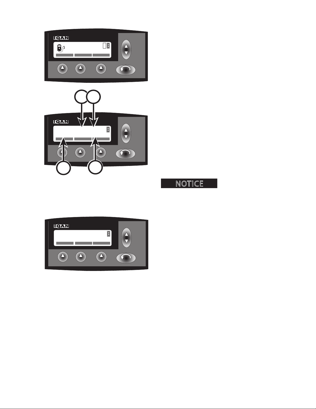
IQAN® CURRENT OUTPUT MEASURE SCREEN
Depress the F2 key to measure outputs.
IQAN.29
C
Scroll using the up & down key to select control
function to measure. Depress the F1 key to measure
control function. IQAN® screen will display:
• control function being measured (A)
• module connected to measured output
control function (B)
A
D
IQAN.42
IQAN.42
• connector number of module (C)
• Current output in milliamps (D)
Understanding measure
functions is key to troubleshooting machine.
Depress the F3 key to view output in graph format.
Depress ESC key to return to previous screen.
Current Outputs (milliamps):
Allows operator to measure the status of current from
IQAN® system to hydraulic valve solenoids. These
components are:
Blade
Up
Down
Left joystick
2546/2548 T3
North-South (N-S)
East-West (E-W)
Right joystick
North-South (N-S)
East-West (E-W)
Steer joystick
Steering
Steering forward
415
1108
Page 46
F1 F2 F3
UP
DN
SCOPE
ESC
DIGITAL OUT
XP-0 C1:18
Grapple Open
LOW
F1 F2 F3
UP
DN
INPUTS OUTPUTS OTHER
ESC
1
MEASURE
1.01
NOTICE
A
F1 F2 F3
UP
DN
SCOPE
ESC
DIGITAL OUT
XP-0 C1:18
Grapple Open
LOW
B
D
C
IQAN®
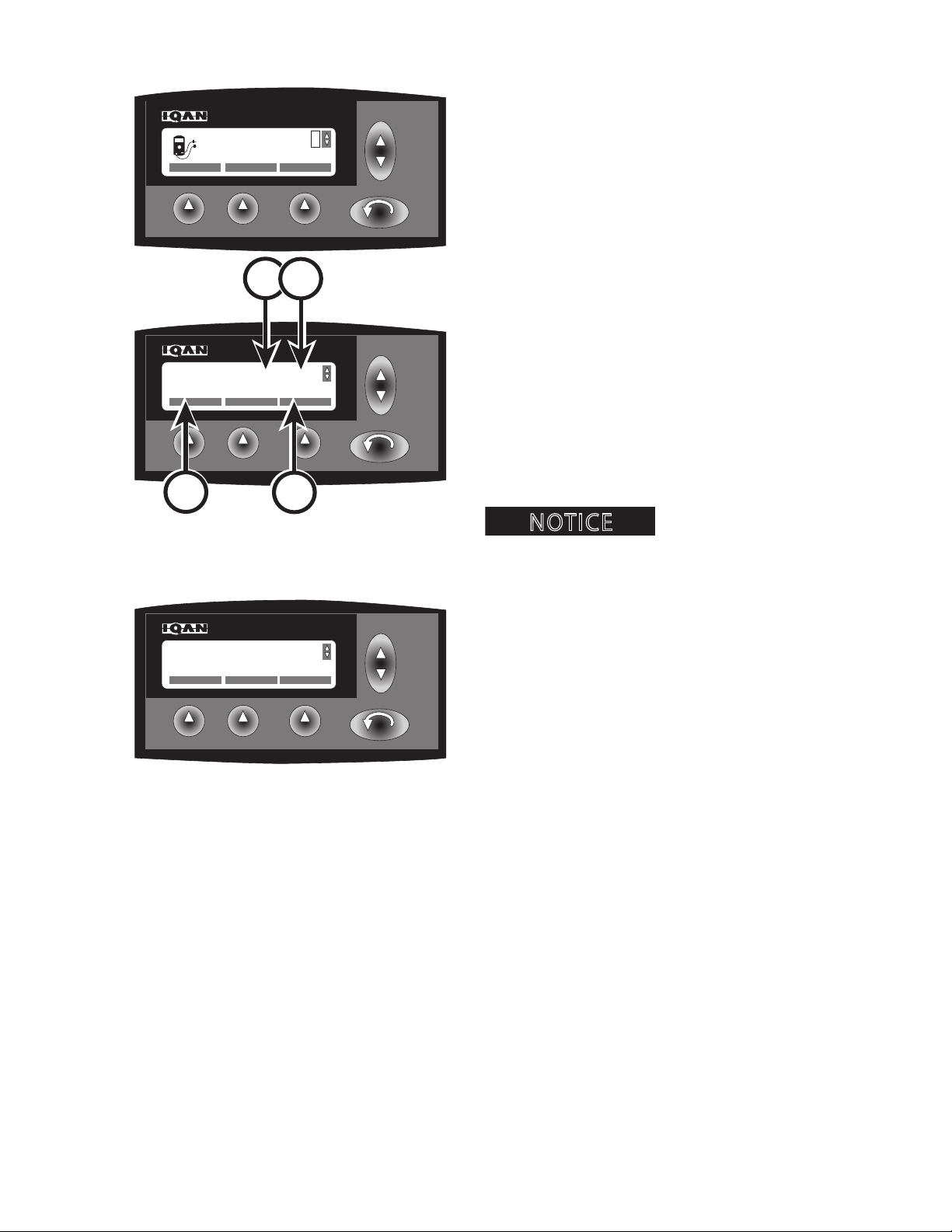
IQAN® DIGITAL OUTPUT MEASURE SCREEN
Depress the F2 key to measure outputs.
IQAN.29
Scroll using the up & down key to select control
function to measure. Depress the F1 key to measure
control function. IQAN® screen will display:
• control function being measured (A)
• module connected to measured output
control function (B)
• connector and pin number of module (C)
IQAN.36
• percent of output to control function (D)
IQAN.36
Understanding measure
functions is key to troubleshooting machine.
Depress the F3 key to view output in graph format.
Depress ESC key to return to previous screen.
Digital Outputs (12 volts):
Allows operator to measure the status of current from
IQAN® system to hydraulic valve solenoids, transmission shift & blade functions. These components are:
Axle
Bogie up
Blade
Up
Down
Boom
Extend
2546/2548 T3
Retract
Clam
Open
Close
416
Grapple
Open
Close
1108
Page 47
IQAN®
F1 F2 F3
UP
DN
ESC
1
OK CANCEL
SELECT MODE
4
F1 F2 F3
UP
DN
ESC
Pressure
PSI
RPM
RPM
1
F1 F2 F3
UP
DN
ESC
1
SELECT COPY RESET
M
MODE
F1 F2 F3
UP
DN
ESC
1
SELECT COPY RESET
M
MODE
NOTICE
F1 F2 F3
UP
DN
ESC
1
OK CANCEL
SELECT MODE
4
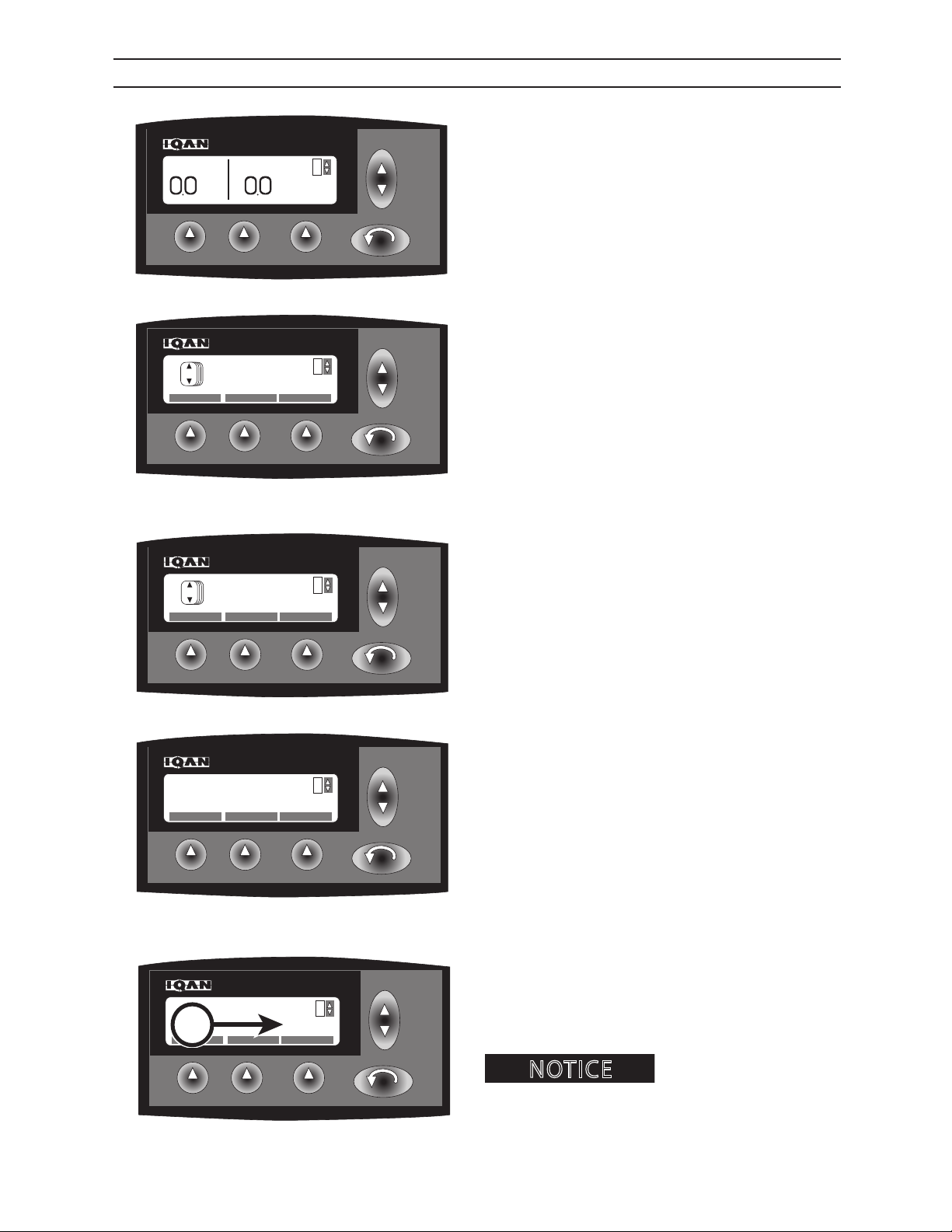
IQAN® MODE SCREEN
Depress the ESC key to access the adjustment menus.
IQAN.44
Scroll using the up & down key until MODE is displayed on the Iqan® screen.
IQAN.12
IQAN.12
IQAN.46
Depress the F1 key to select operator mode adjustment .
Scroll using the up & down key to select operator
mode.
Depress the F1 key to select desired operator mode (A)
displayed on Iqan® screen (1-4).
2546/2548 T3
A
After selection of operator mode, IQAN® will automatically return to main menu.
Operator’s are able to set
IQAN.46
parameters to meet each operator’s specic preferences.
The IQAN® can store up to 3 dierent operator modes
(with mode 4 being the factory default).
417
1108
Page 48
F1 F2 F3
UP
DN
ESC
1
SELECT COPY RESET
M
MODE
NOTICE
A
F1 F2 F3
UP
DN
ESC
1
OK CANCEL
COPY FROM MODE
4
F1 F2 F3
UP
DN
ESC
COPYING..........
IQAN®
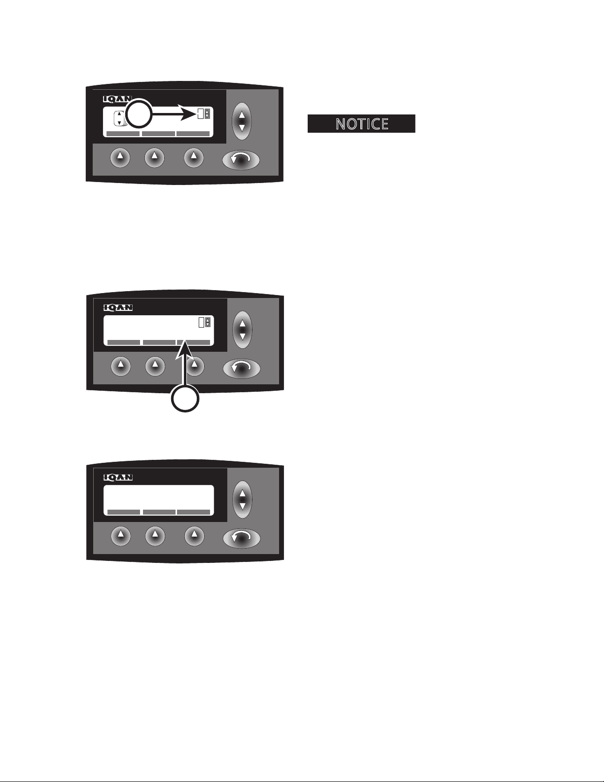
IQAN® COPY MODE SCREEN
Depress the F2 key when desired operator mode to
program (A) is displayed on IQAN® screen (1-4) .
conditions, primary operator has set optimal parameters
in operator mode 1, this mode can be copied and altered
to second and third operator parameters. Operator mode
4 is factory default and can not be altered.
IQAN.12
Example: Operator mode 1 is being dened on screen.
Select F2 key to copy parameters to operator mode 1.
Scroll using the up & down key to select desired operator mode to copy (B) is displayed on IQAN® screen (1-4)
. Depress the F1 key to select copy function. Select F2
key to cancel.
Under normal operating
B
Example: Operator mode 1 is being dened on screen.
Parameters from operator mode 4 will be copied to
operator mode 1.
IQAN.13
After selection of mode to copy, copying screen will be
displayed on IQAN® screen until function is complete.
Operator will be returned to main mode screen after
copy function is complete.
IQAN.14
2546/2548 T3
418
1108
Page 49

F1 F2 F3
UP
DN
ESC
1
SELECT COPY RESET
M
MODE
NOTICE
A
F1 F2 F3
UP
DN
ESC
1
OK CANCEL
CONFIRM RESET
F1 F2 F3
UP
DN
ESC
RESETTING......
IQAN®
IQAN® RESET MODE SCREEN
Depress the F3 key (A) when operator mode (B) to be
reset is displayed on IQAN® screen (1-3) .
Operator modes 1-3 are able
to be reset. Reset function will automatically reset selected operator mode to operator mode 4, factory default.
IQAN.12
IQAN® screen will ask to verify that you would like to
reset . Depress F1 key to continue, F2 key to cancel and
return to mode screen.
IQAN.15
IQAN.15
After selection of mode to reset, resetting screen will
be displayed on IQAN® screen until function is complete. Operator will be returned to main mode screen
after reset function is complete.
2546/2548 T3
419
1108
Page 50
IQAN®
F1 F2 F3
UP
DN
ESC
Pressure
PSI
RPM
RPM
1
F1 F2 F3
UP
DN
ESC
1
APPLIC MODULES
INFORMATION
i
F1 F2 F3
UP
DN
ESC
050405 08:52:32
0000001FD838
Fabtek/Engineering
F1 F2 F3
UP
DN
ESC
050405 08:52:32
0000001FD838
Fabtek/Engineering
F1 F2 F3
UP
DN
ESC
500 Series LH Boom 03.71
More... Comment
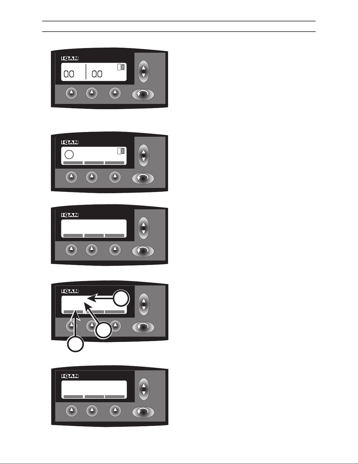
IQAN® INFORMATION SCREEN
Depress the ESC key to access the adjustment menus.
Scroll using the up & down key until INFORMATION is
displayed on the IQAN® screen.
IQAN.44
Depress the F1 key to view basic information about
the operating application.
C
B
A
IQAN.17
Depress the F1 key to view detailed information about
the operating application.
IQAN.47
IQAN® screen will display date (A) and time of most
recent update, program identication information (B)
and key identication (C) of person/company performing update.
IQAN.18
2546/2548 T3
Depress ESC key to return to basic information screen.
Note: Depress ESC key again to return to main screen.
IQAN.18
420
1108
Page 51
IQAN®
F1 F2 F3
UP
DN
ESC
1
APPLIC MODULES
INFORMATION
i
F1 F2 F3
UP
DN
ESC
4 Operators Mode Swing Pressure
F1 F2 F3
UP
DN
ESC
1
APPLIC MODULES
INFORMATION
i
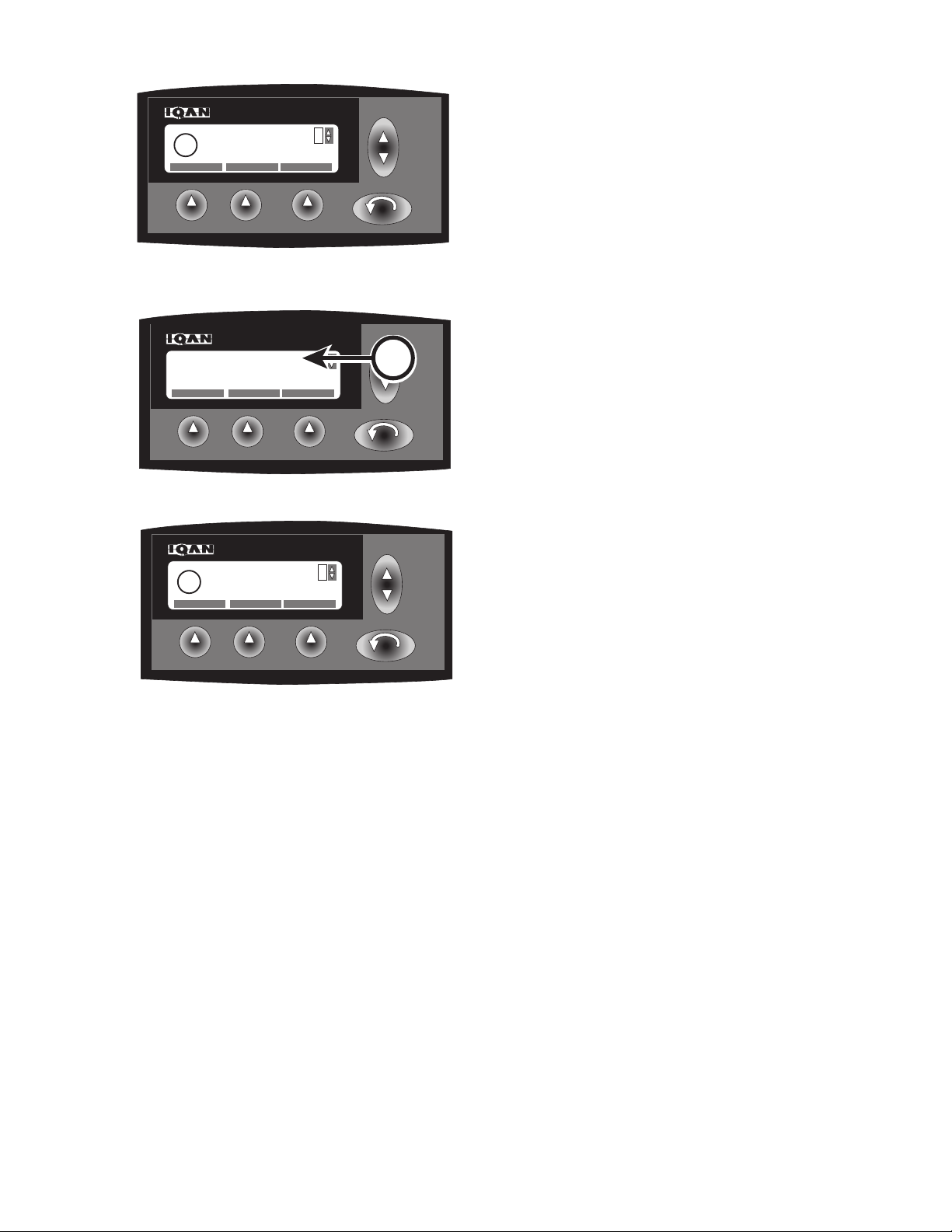
IQAN® INFORMATION SCREEN
Depress the F2 key to view information about the
operating comments.
IQAN.17
4 operators mode swing pressure (A) will display on
A
IQAN.48
screen.
IQAN.17
Depress ESC to return to basic information screen.
Note: Depress ESC key again to return to main screen.
2546/2548 T3
421
1108
Page 52
IQAN®
F1 F2 F3
UP
DN
ESC
1
APPLIC MODULES
INFORMATION
i
F1 F2 F3
UP
DN
ESC
STATUS INFO SW INFO HW
Module: MDM
F1 F2 F3
UP
DN
ESC
INTERNAL
Module: MDM
Status: ENABLED
F1 F2 F3
UP
DN
ESC
INTERNAL
Module: MDM
Status: ENABLED
F1 F2 F3
UP
DN
ESC
Module: MDM
VBat : 11.9
Temp : 44.2 Util : 24.0
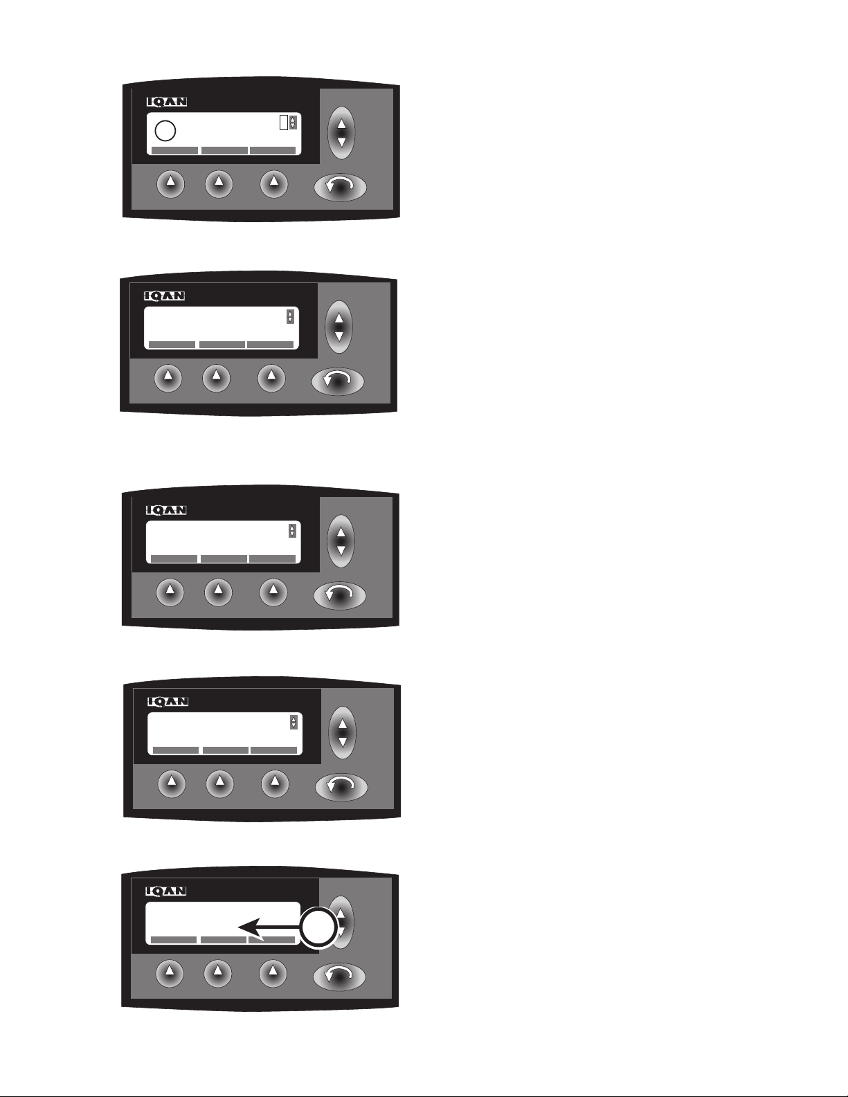
IQAN® INFORMATION SCREEN
Depress the F2 key to view information about the
operating modules.
IQAN.17
Using the up & down key scroll through modules to
be selected (MDM).
Note:
Modules information is available on are:
MDM
Lx-A2
IQAN.19
IQAN.49
LX-A1
LX-A0
XP-A0
Depress F1 to view status of module displayed on
IQAN® screen (enabled/disabled) (MDM).
Note: Depress the ESC key to return to main module
screen.
Depress F2 to view internal information of module
displayed on IQAN® screen (MDM).
2546/2548 T3
IQAN.49
Display will provide detailed information about the
battery voltage, temperature and utility pressure (A).
A
IQAN.50
Note: Depress the ESC key to return to main module
screen.
422
1108
Page 53
IQAN®
F1 F2 F3
UP
DN
ESC
Module: MDM
HWVer : 01.39
HW Ser : 02445 Hours : 50
PDate : 010705
F1 F2 F3
UP
DN
ESC
STATUS INFO SW INFO HW
Module: MDM
F1 F2 F3
UP
DN
ESC
Module: MDM
SWVer : 03.71
SWCheck : 8F75 IDPVer : 06.02
SWEAN : 58010
F1 F2 F3
UP
DN
ESC
STATUS INFO SW INFO HW
Module: MDM
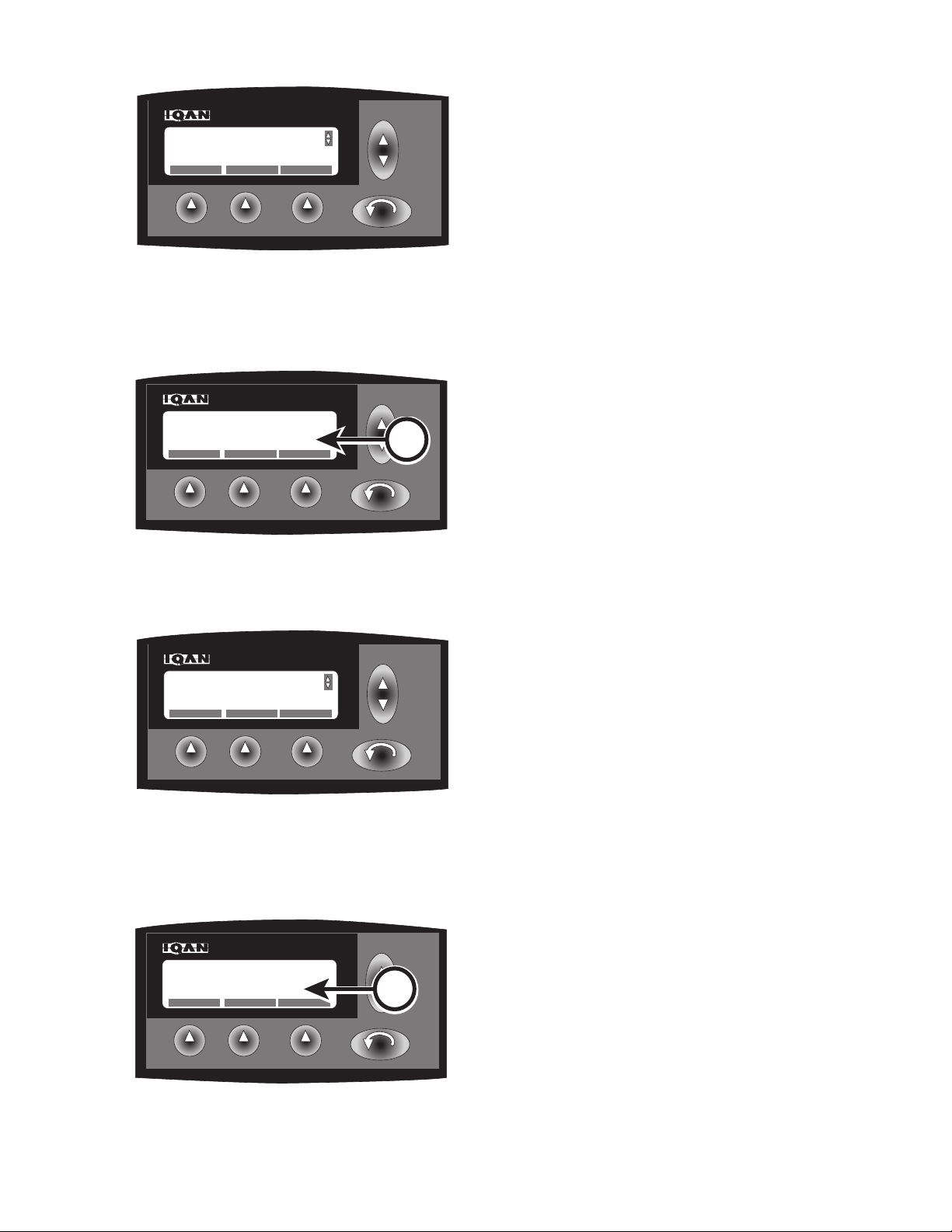
IQAN® INFORMATION SCREEN
Depress the F2 key to view detailed software information about the operating module selected (MDM).
Note:
Modules for which information is available are:
MDM
Lx-A2
IQAN.19
LX-A1
LX-A0
XP-A0
Display will provide software version, check, EAN and
IDP version (A).
A
IQAN.51
IQAN.19
Note: Depress the ESC key to return to main module
screen.
Depress the F3 key to view detailed hardware information about the operating module selected (MDM).
Note:
Modules for which information is available are:
MDM
Lx-A2
LX-A1
LX-A0
XP-A0
2546/2548 T3
Display will provide detailed information about the
hardware version, serial number, Pdate and hours (B).
B
Note: Depress the ESC key to return to main module
screen. Depress the ESC key again to return to main
information screen.
IQAN.52
423
1108
Page 54
IQAN®
F1 F2 F3
UP
DN
OUTPUTS
ESC
1
PROPERTIES
+
-
F1 F2 F3
UP
DN
OUTPUTS
ESC
1
PROPERTIES
+
-
F1 F2 F3
UP
DN
ESC
Pressure
PSI
RPM
RPM
1
NOTICE
F1 F2 F3
UP
DN
SELECT (+) SELECT (-)
AUTO
ESC
SELECT FUNCTION
Right N-S
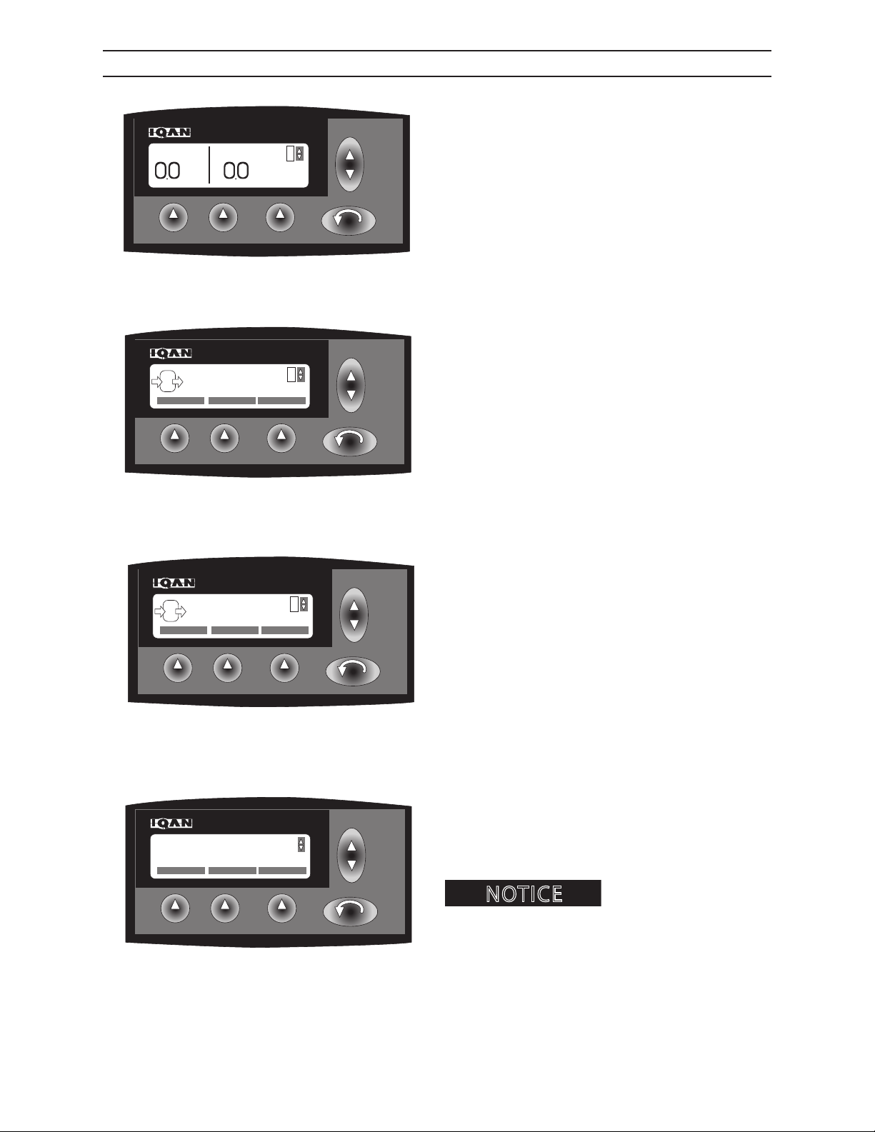
IQAN® PROPERTIES SCREEN
Depress the ESC key o access the adjustment menus.
IQAN.44
Scroll using the up & down key until PROPERTIES is
displayed on the Iqan® screen.
IQAN.37
IQAN.37
Depress the F2 key to read and/or adjust property
outputs.
Depress F1 key to increase (+) current.
Depress F2 key to decrease (-) current.
Depress F3 key to set current by usage (auto).
2546/2548 T3
Setting control function
automatically (F3) will set function to perform in manner
joystick is moved with auto selected.
IQAN.39
424
1108
Page 55
IQAN®
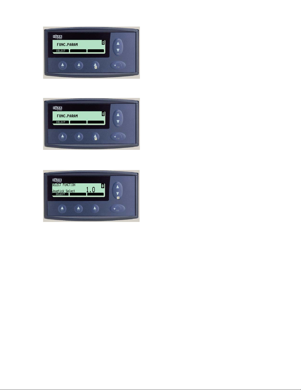
IQAN® PROPERTIES SCREEN
Depress the F3 key to select other parameters.
Scroll using the up & down key until FUNC. PARAM is
displayed on the Iqan® screen.
Depress the F1 key to display function settings.
2546/2548 T3
425
1108
Page 56
IQAN®
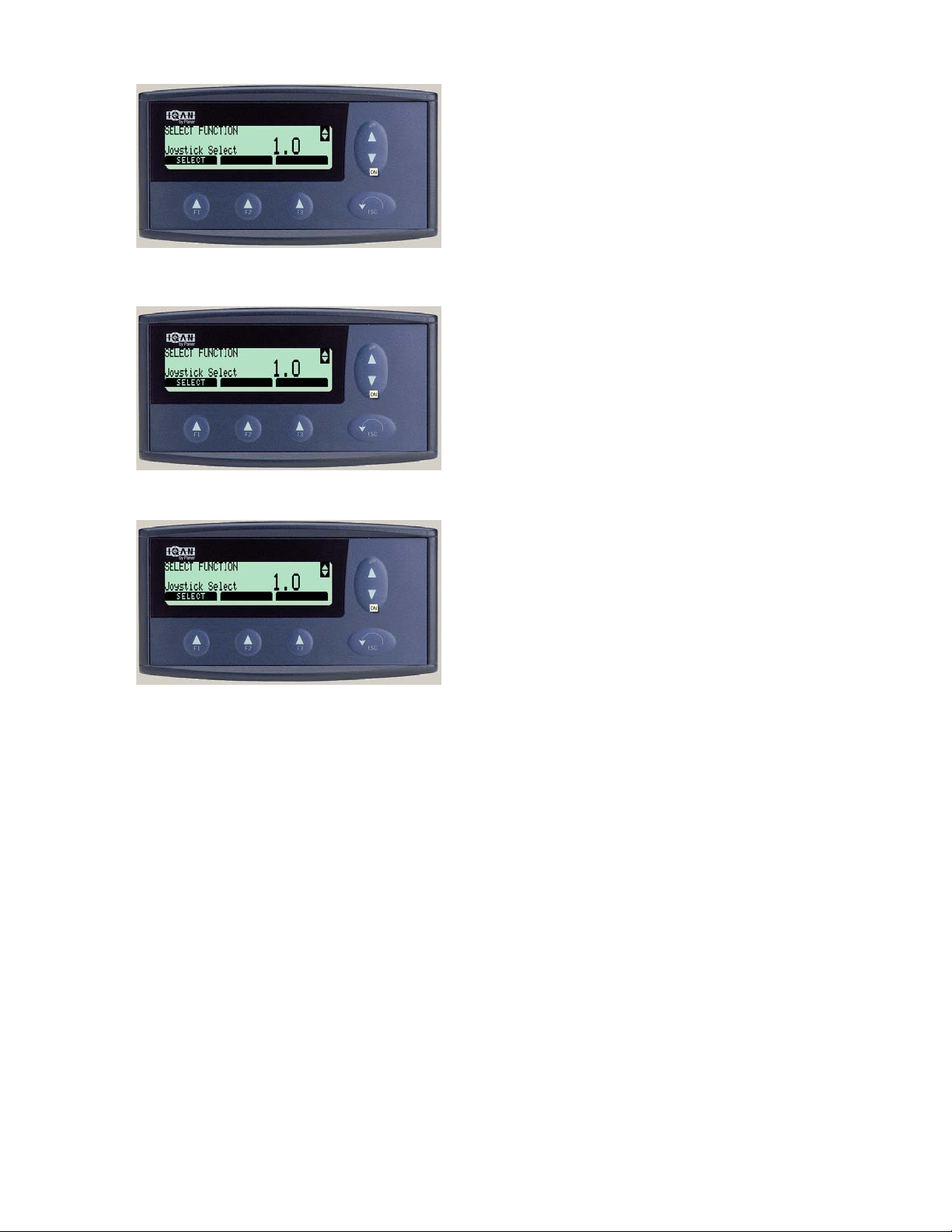
IQAN® PROPERTIES SCREEN
Scroll using the up & down key to select between Joystick Select and Steering Mode displayed on the Iqan®
screen. Depress F1 to select function.
Scroll using the up & down key to select between Joystick 1.0 (Forestry Mode) and Joystick 2.0 (SAE Mode)
displayed on the Iqan® screen. Depress F1 to select
mode. Depress F2 to cancel. Depress F3 to reset.
Scroll using the up & down key to select between
Steering 1.0 (Standard Mode) and Steering 2.0 (Optional Mode) displayed on the Iqan® screen. Depress
F1 to select mode. Depress F2 to cancel. Depress F3 to
reset.
2546/2548 T3
426
1108
Page 57
CONTROLS AND INSTRUMENTS
CONTROLS AND INSTRUMENTS
OPERATOR’S STATION
10
18
17
5
3
1
6
7
14a, 14b
19
12
13
15
4
16
105.08
9
8
2
11
2546/2548 T3
1. Throttle Pedal (rear facing)
2. Throttle Pedal (front facing)
3. Brake Pedal (rear facing)
4. Brake Pedal (front facing)
5. Foot Shift Pedal
6. Throttle Lock Pedal
7. Throttle Lock Release
8. Climate Control
9. Transmission Control/Side Panel
10. Rear Console
11. Front Console
12. Steering Joystick
13. Boom Control Joystick (rear facing)
14a. Boom Control Joystick (rear facing)
14b. Blade control Joystick (forward facing)
15. Arm Rest Console
16. Stereo
17. Dome Light
18. IQAN®
19. Gauge Panel
51
1108
Page 58
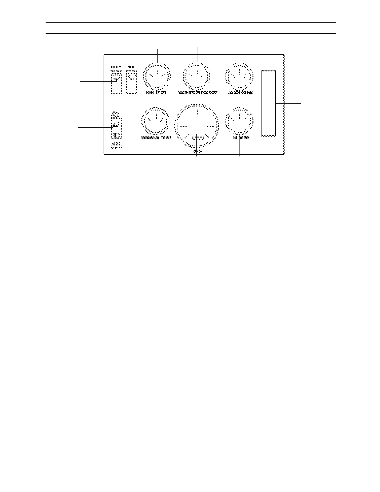
CONTROLS AND INSTRUMENTS
GAUGE CLUSTER ASSEMBLY
9
8
7
1
6
2
3
4
5
106.08
1. Wiper Switches
2. Light Switch
3. Transmission Temperature Gauge
4. Tachometer/Hourmeter
5. Hydraulic Temperature Gauge
6. Warning Indicator Panel
7. Oil Pressure Gauge
8. Cooling Temperature Gauge
9. Fuel Level Gauge
2546/2548 T3
52
1108
Page 59
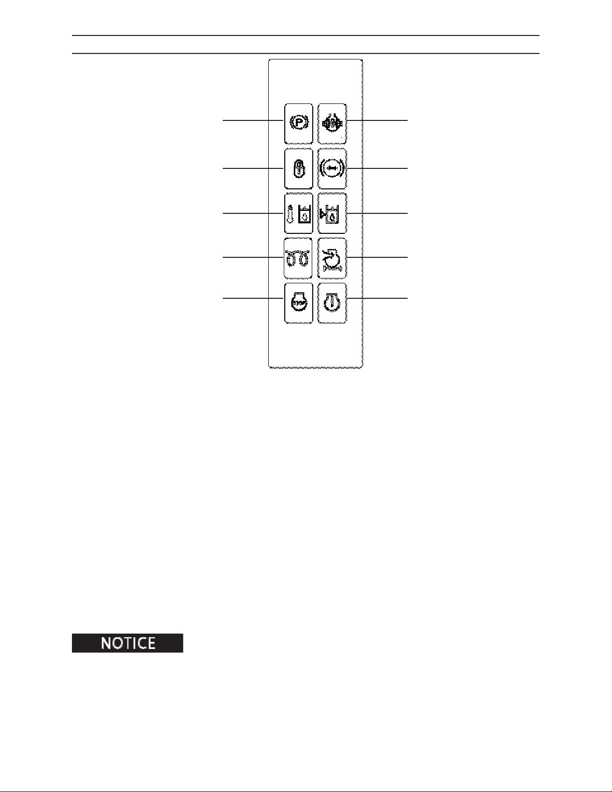
CONTROLS AND INSTRUMENTS
WARNING INDICATOR PANEL
1
2
3
4
5
1. Park Brake Icon - Red Indicator
6
7
8
9
10
2. Frame Lock Icon - Green Indicator
3. Hydraulic Oil Temperature Icon - Red Indicator
4. Wait To Start Icon - Yellow Indicator
5. Engine Urgent Stop Icon - Red Indicator
6. Dierential Lock Icon - Green Indicator
7. Brake System Pressure Icon - Red Indicator
8. Hydraulic Oil Level Icon - Red Indicator
9. Engine Intake Filter Icon - Yellow Indicator
10. Engine Failure Warining Icon - Yellow Indicator
When the indicator illuminates, shut engine down and contact an authorized dealer.
2546/2548 T3
53
1108
Page 60
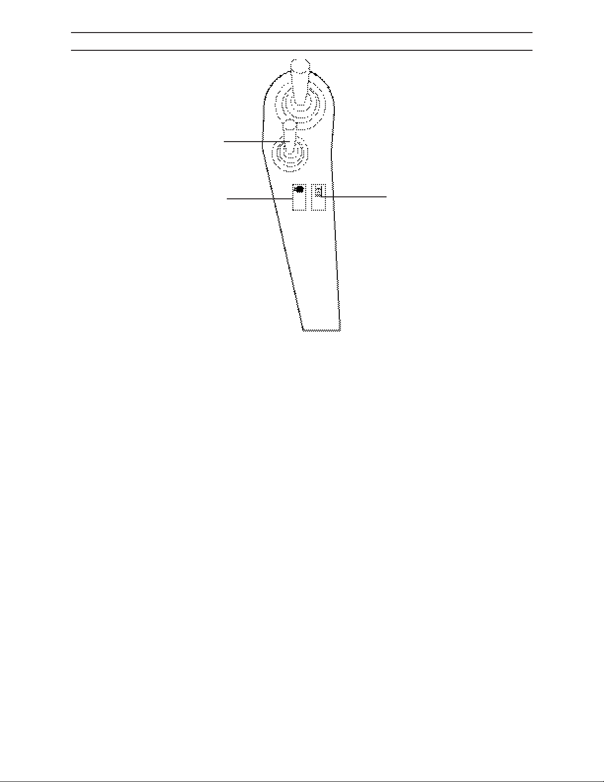
CONTROLS AND INSTRUMENTS
LEFT SIDE CONSOLE
1
2
1. Steering Joystick
2. Foot Shift Activation Switch
3. Load Sense Dump Switch
3
109.08
2546/2548 T3
54
1108
Page 61
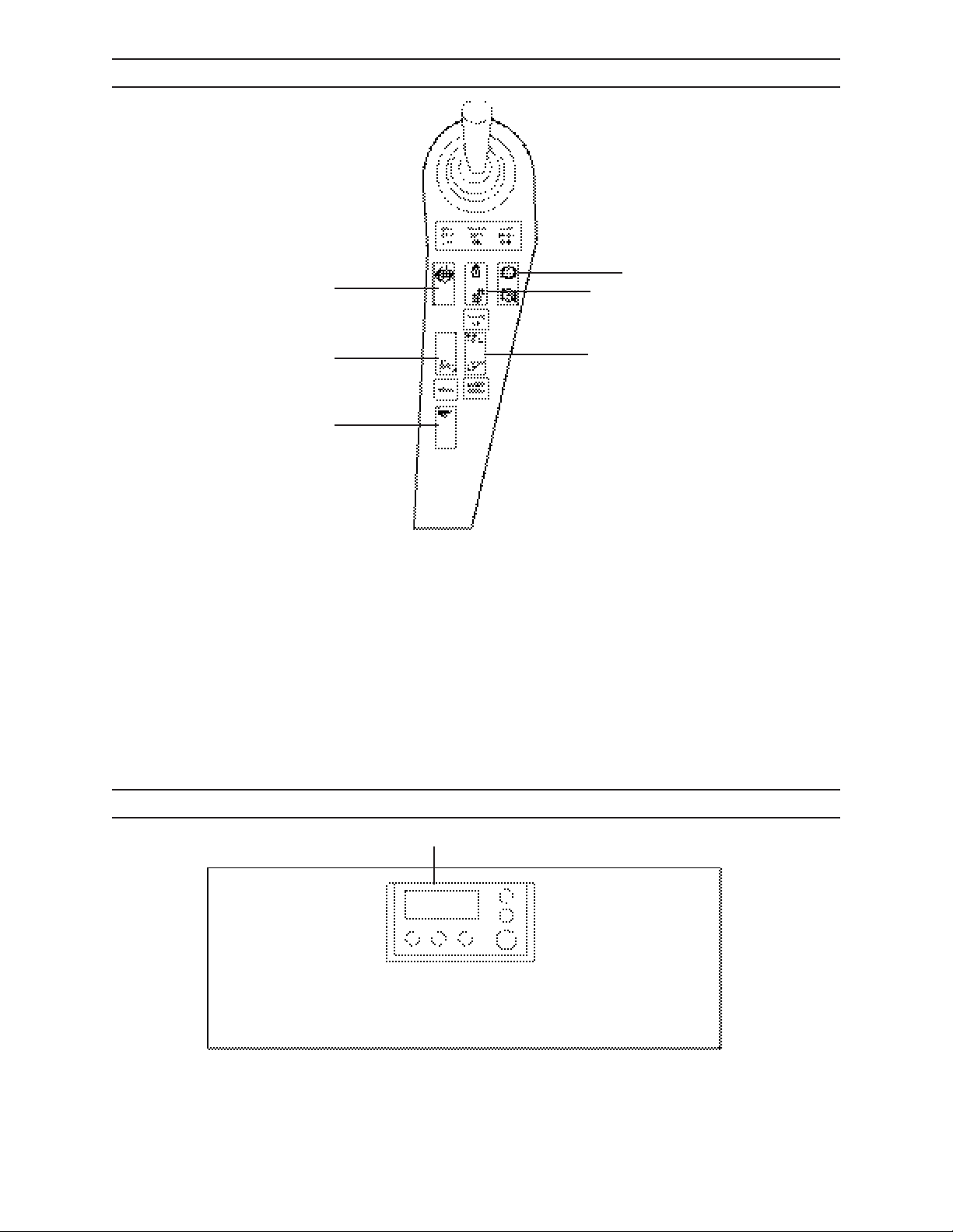
CONTROLS AND INSTRUMENTS
RIGHT SIDE CONSOLE
1
6
5
1. Dierential Lock Switch
2. Frame Lock Switch
3. Park Brake Switch
4. Blade Control Switch (rear facing)
5. Horn Switch
6. Blade Float Switch (forward & rear facing)
3
2
4
108.05
2546/2548 T3
REAR CONSOLE
1
1. IQAN® Display
55
107.08
1108
Page 62
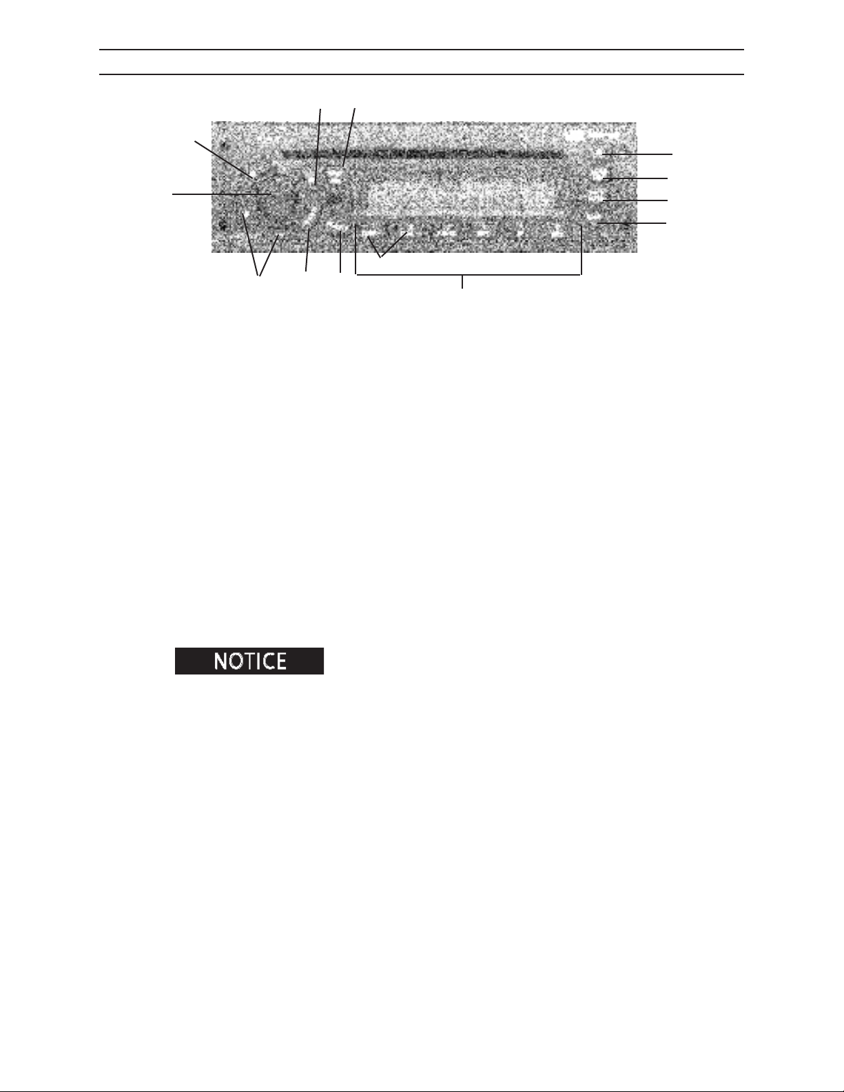
CONTROLS AND INSTRUMENTS
SATELLITE RADIO
12
3
4
5
11
13
6
10
2
0108 SAT
7
1. Eject Button - Ejects CD
2. Band Button - Switches between AM, FM1, FM2, FM 3, SAT1, SAT2, WX and Auxilary modes
3. Time Set/Display Button - Switches to time set mode/changes display
4. Power Button - Powers radio on and o
5.On/Audio Knob - Power/volume/receiver settings
6. +Tune/Seek- Button - Changes radio station or CD/MP3 track.
7. 1-6 Buttons - Selects preset stations/CD/CP3 functions
8. Pre-set Scon/Auto Button - Scans presets on current band/stores strangest stations to pre-set
9. Scan/Dim Button - Scans all stations in current band or on CD/MP3
10. Alarm Button - Selects alarm set mode
11. Random Button - Plays CD/MP3 tracks roandomly
12. CD Button - Switches to CD/MP3 mode
13. Foler +/- Buttons - Changes folders on MP3
1
9
8
2546/2548 T3
Refer to radio operator’s manual to program key/button functions.
56
1108
Page 63
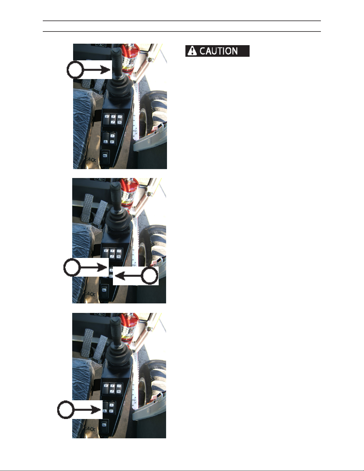
CONTROLS AND INSTRUMENTS
BLADE CONTROL
Do not use blade for ex-
cavating, paving or removing stumps. Doing so can
A
result in machine damage.
FRONT BLADE FACING CONTROLS:
1. Raise blade by pulling blade joystick (A) back.
2. Lower blade by pushing blade joystick (A) forward.
REAR BOOM FACING CONTROLS:
1. Raise blade by depressing blade control switch
(B).
2. Lower blade by depressing blade control switch
(C).
B
C
BLADE FLOAT BLADE & BOOM FACING
CONTROLS OPTION:
1. Select blade oat option by depressing blade
oat switch (D).
D
2546/2548 T3
57
1108
Page 64
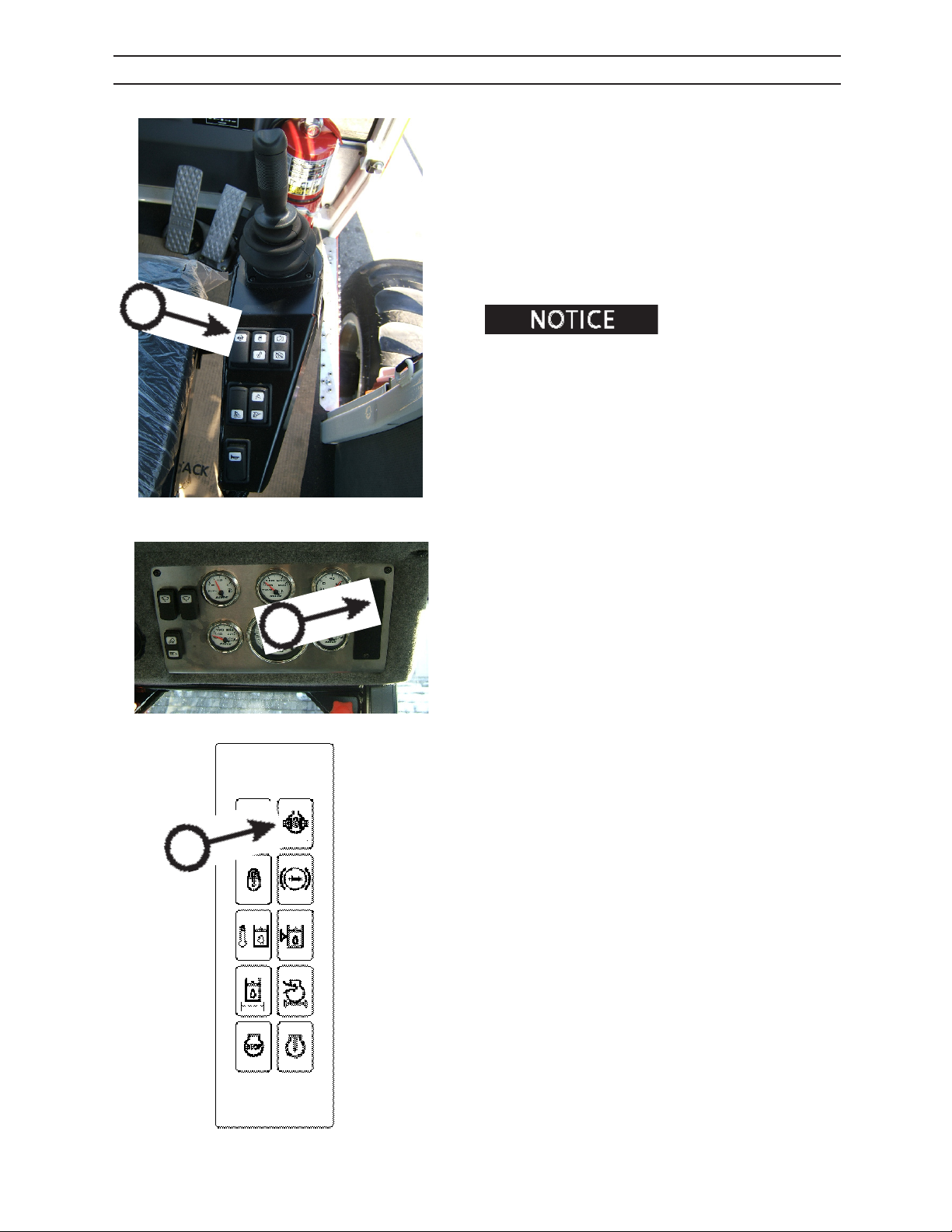
CONTROLS AND INSTRUMENTS
AXLE DIFFERENTIAL LOCK
The dierential lock locks out the dierential. This
prevents the usual loss of traction when one wheel is
slipping.
When using switch on side console:
1. Shift transmission to neutral.
2. Depress switch (A) on side console.
3. Dierential lock indicator
(green indicator) will illuminate when axle is locked.
light on gauge panel (b)
A
Lock the axles ONLY in low
traction conditions. Axle damage can result if dierential
is operated in the locked mode all of the time.
4. Release switch on control panel to unlock dierential lock.
B
0108 GAUGE PANEL
B
2546/2548 T3
58
1108
Page 65
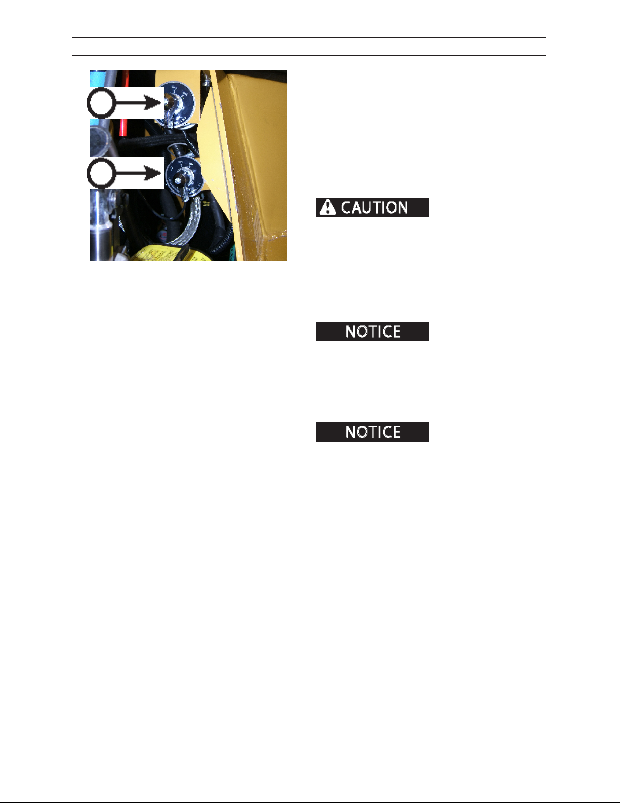
CONTROLS AND INSTRUMENTS
BATTERY DISCONNECT MASTER SWITCHES
The battery disconnect master switches (A & B) are
located in the LH engine compartment, and are
A
B
DCSF2399
designed to prevent accidental starting of the engine
while servicing machine, prevent accidental battery
drain, and to deter vandalism.
Turn primary battery disconnect master switch (A) OFF
to disconnect the electrical system.
Turn secondary battery disconnect master switch (B)
OFF to disconnect the Pro-heat system.
Do not turn either master
disconnect switch o while engine is running. Doing
so will cause loss of electrical power, resulting in
personal injury or property damage.
Turn primary battery disconnect master switch (A) ON
to connect the main electrical system.
Turn secondary battery disconnect master switch (B)
ON to connect the Pro-heat electrical system.
There needs to be a minimum 30 second delay between when the engine is shut
down and when the battery disconnect master is shut o
to allow the ECU to store information. If this is not done,
some of the historical operating parameter information
will not be properly stored, and fault codes will be generated.
Pro-Heat option is functional
with main battery master disconnect switch in OFF position.
2546/2548 T3
59
1108
Page 66
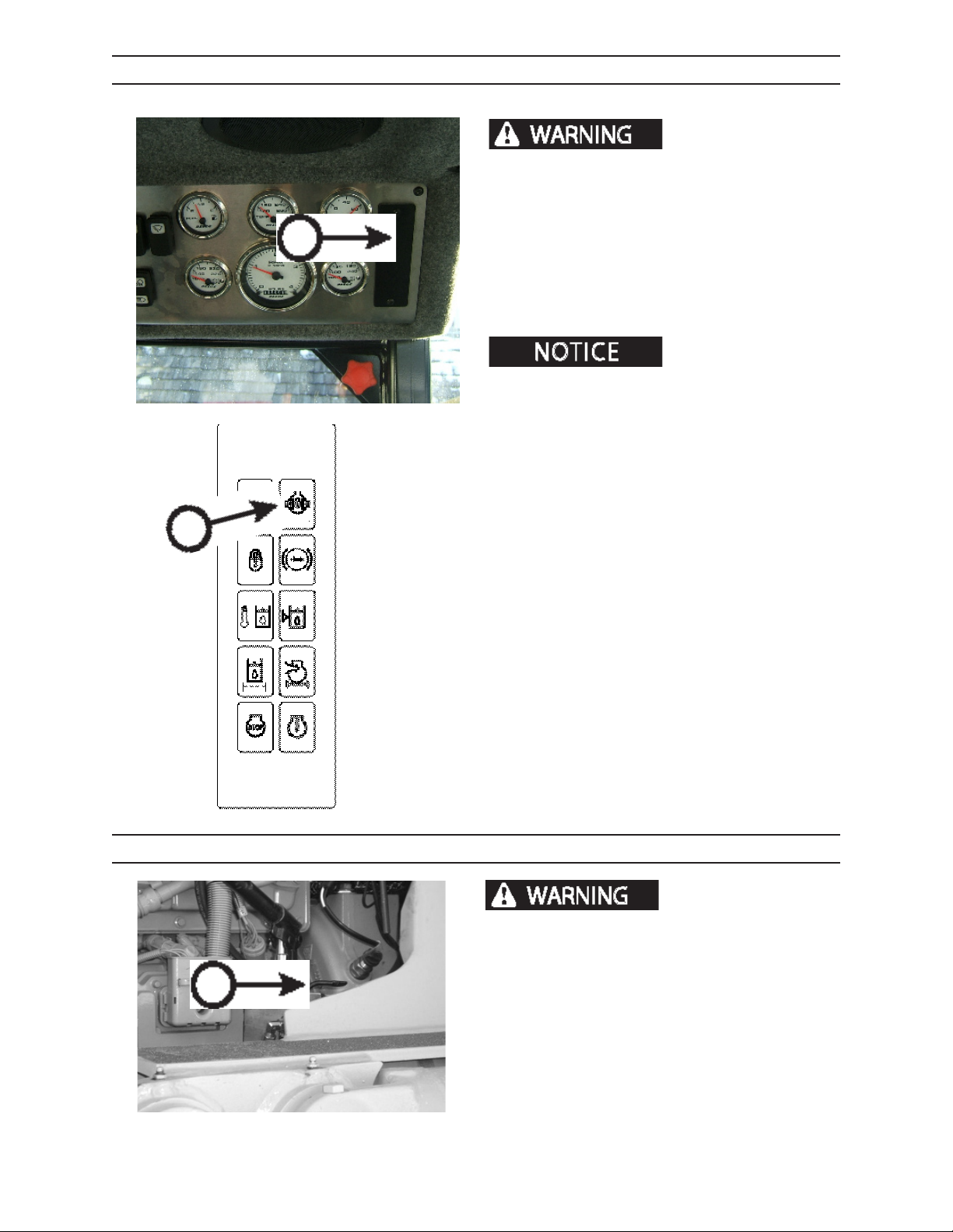
CONTROLS AND INSTRUMENTS
BRAKE LOW PRESSURE INDICATOR
with out brake pressure can cause serious personal
injury or death.
Low brake pressure indicator on gauge panel (red indi-
A
0108 GAUGE PANEL
cator) (A) will illuminate if brake pressure is lost.
Do not operate machine with brake low pressure
indicator illuminated.
Indicator will shut o when brake pressure is at
specied level.
will discharge with each depression of the brake pedal.
After 5 depressions light brake pressure is still available.
After 8 depressions no brake pressure is available.
Operating forwarder
Brake pressure accumulator
A
CAB TILT CONTROL
NEVER get under a tilted
cab UNLESS cab is completely tilted and locked into
position. If a hydraulic hose or component failure occurs, cab could accidentally lower unexpectedly and
B
cause serious personal injury.
2546/2548 T3
Move hydraulic pump control lever (B) to raise or lower
cab.
For more information on cab tilt procedures, see
Operation section.
52413
510
1108
Page 67
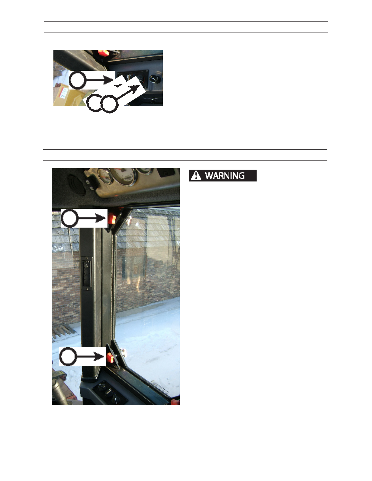
A
CONTROLS AND INSTRUMENTS
CLIMATE CONTROLS
CONTROL KNOBS
A. Fan speed.
B. Temperature control.
A
C
B
0108 TRANS CON SOLE
C. Knob turned clockwise selects outside air, air
conditioning or heat.
EMERGENCY EXITS
Debris such as limbs and
branches coming through window openings can
cause severe personal injury or death. Never operate forwarder without Tuax ® window locked in
place.
USING SIDE WINDOW EXITS
A
1. Loosen window knobs until loosened.
2. Push on window until window falls out.
2546/2548 T3
0108 WINDOW E XIT
511
1108
Page 68
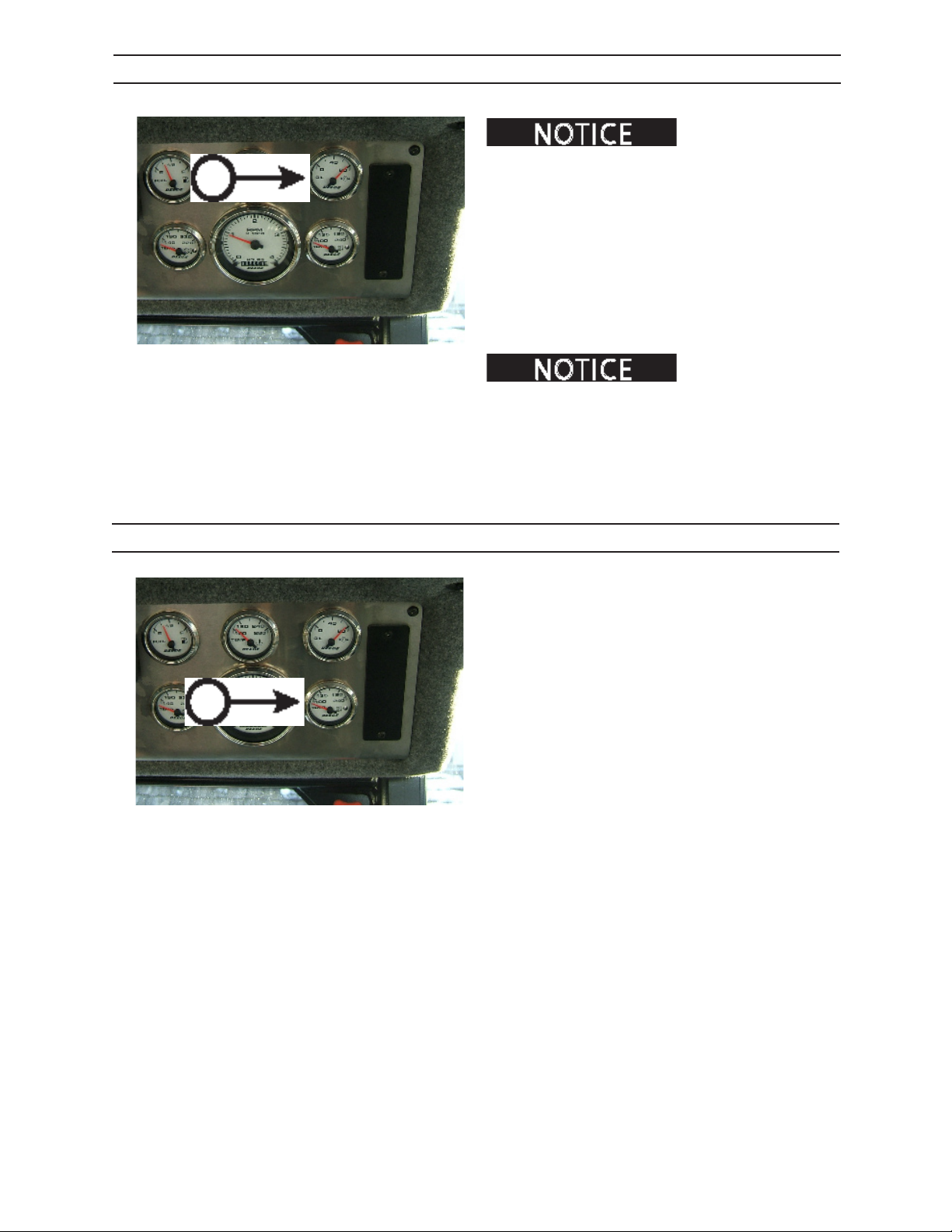
A
CONTROLS AND INSTRUMENTS
ENGINE OIL PRESSURE GAUGE
If NO oil pressure is
indicated in 10 to 15 seconds at start-up, stop engine and
check the lubricating oil system.
CATERPILLAR ENGINE
Minimum engine oil pressure (A) is 10 psi (69 kPa) at
idle. The minimum oil pressure at normal operating
speed is 30 psi (207 kPa).
Engine operating temperature and oil viscosity will
aect oil pressure readings.
0108 GAUGE PANEL
Oil pressure DOES NOT
guarantee there is a sucient amount of oil in the engine
oil pan. Check engine oil level by observing the level on
the dipstick.
B
ENGINE TEMPERATURE GAUGE
The engine temperature gauge (B) monitors the
engine coolant temperature.
Normal engine coolant operating temperature is 190210°F (88-99°C).
If operating above mormal operating temperature,
check radiator and oil cooler ns for debris or damage. For maximum air ow, keep area in front of the
radiator clean.
0108 GAUGE PANEL
2546/2548 T3
512
1108
Page 69
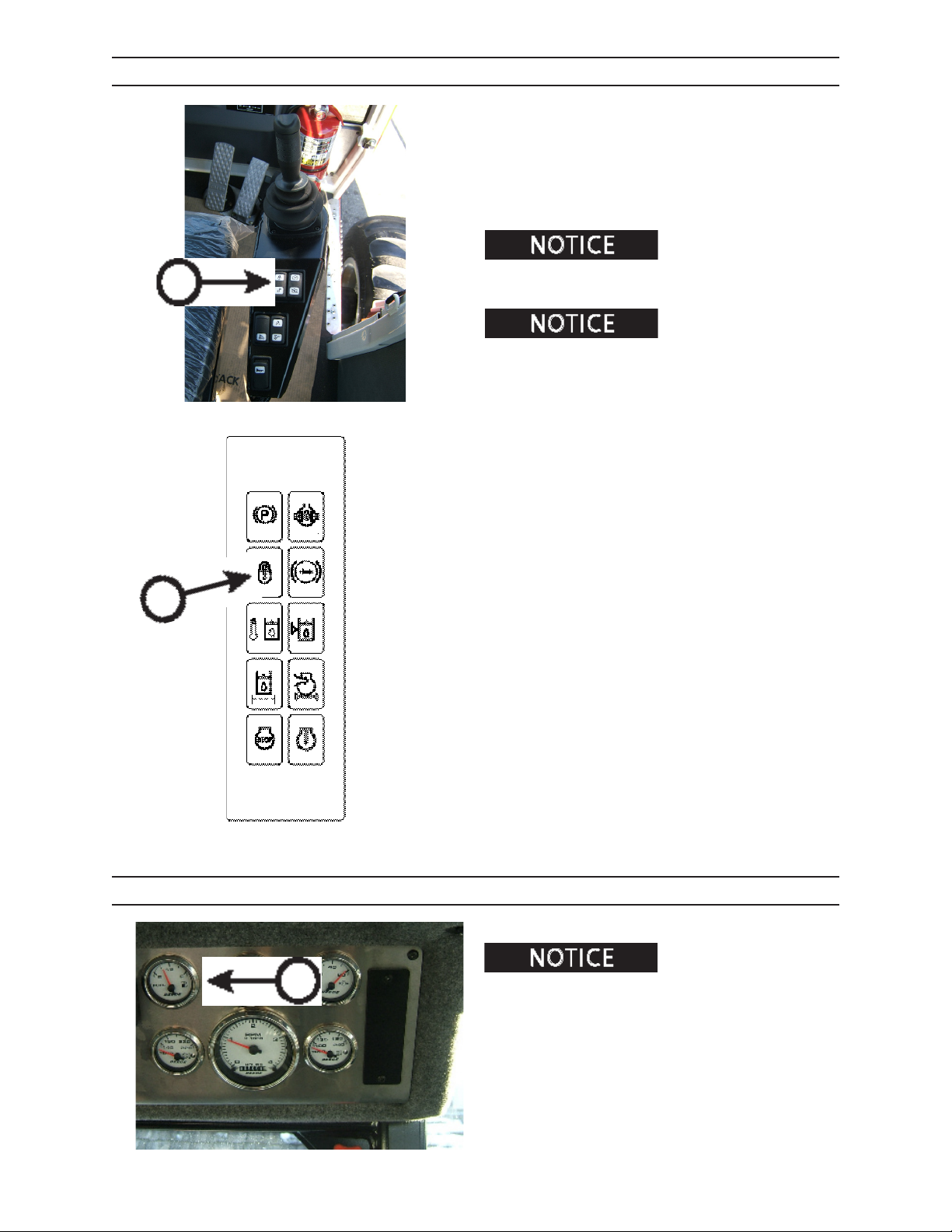
A
CONTROLS AND INSTRUMENTS
FRAME LOCK SWITCH
The frame lock switch (A) locks the cylinder on the
oscillation joint and stops the frame from oscillating.
With frame lock switch in “on” position, frame lock is
automatically activated and Frame Lock icon will iluminate (green indicator) when transmission is placed in
neutral.
When the foot shifter is
activated, the frame lock is engaged. See transmission
console and travel pedals within this section.
Frame lock should be kept
“on” under normal operating conditions. If necessary
to oscillate when in neutral, Frame Lock Switch can be
turned o.
A
FUEL INDICATOR
B
to run out of fuel. Doing so will cause engine damage.
The fuel gauge (B) shows the level of fuel in the fuel
tank. The fuel tank capacity is 46 gallons (181 L).
Do not allow a diesel engine
2546/2548 T3
0108 GAUGE PANEL
513
1108
Page 70
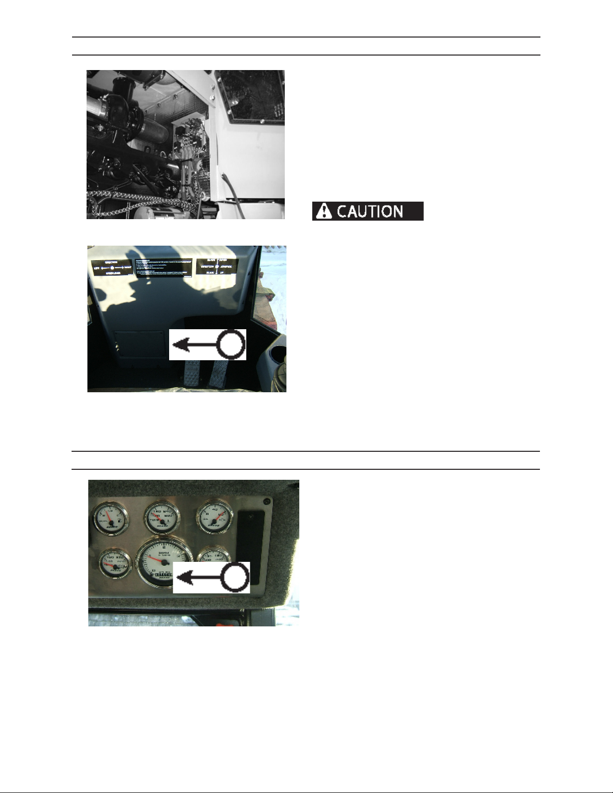
CONTROLS AND INSTRUMENTS
FUSE AND RELAY PANEL
Wiring circuits are protected from short circuits by
fuses. The fuse/relay panels are located in the front
dash panel (A) and the LH engine compartment.
Fuses protect electrical circuits from current overload.
This greatly reduces the chance of res caused by
electrical problems.
To replace the fuse, make sure to have same amperage
rating, gently remove fuse and replace by sliding
replacement fuse into place.
A
524.47
amperage rating to replace “blown” fuses. Doing so
can cause electrical res. Diagnose and correct the
problem that caused the fuse to “blow”.
0108 ELEC ACC ESS
HOURMETER
The hourmeter (B) registers in full hours and tenths of
hours.
Do not use fuses of higher
2546/2548 T3
B
0108 GAUGE PANEL
514
1108
Page 71
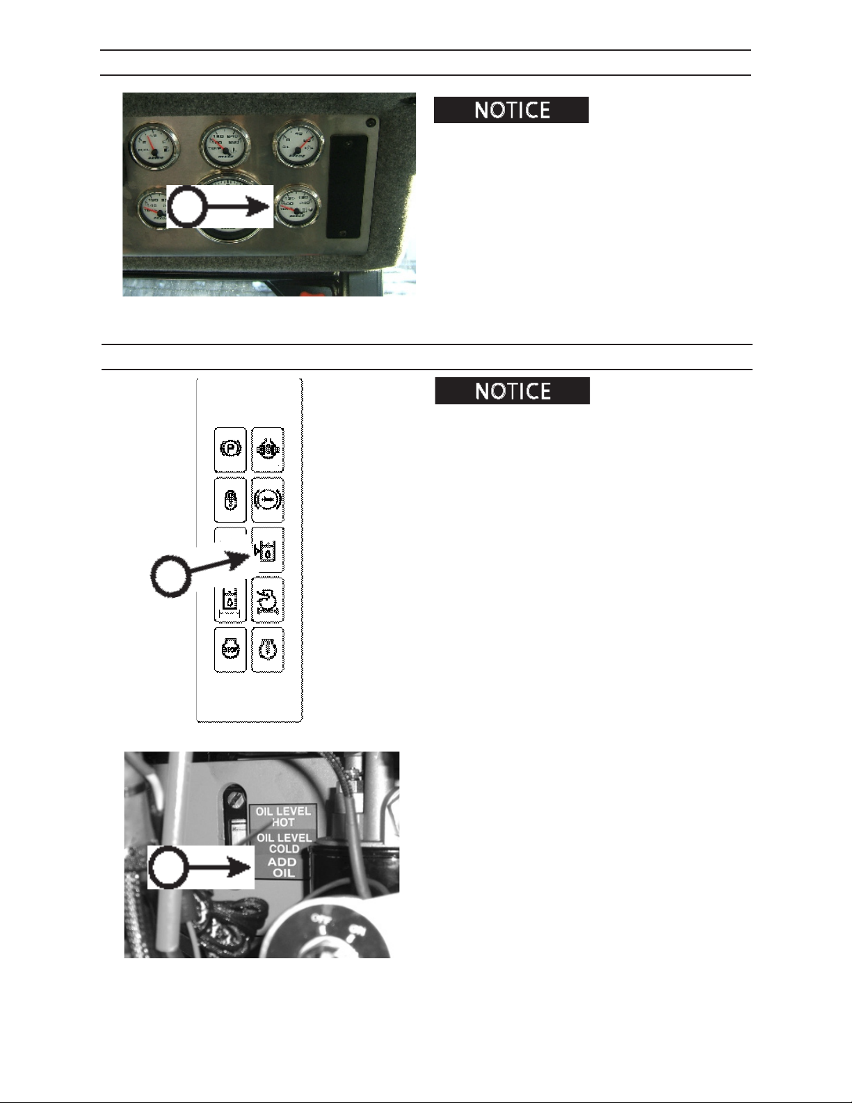
A
CONTROLS AND INSTRUMENTS
HYDRAULIC OIL TEMPERATURE INDICATOR
Possible pump or hydraulic
system damage can occur if opperating for an extended
period of time above 190° F (88° C).
Normal hydraulic operating temperature is 145° F to
185° F (63°C to 85°C) (A).
If temperature on hydraulic oil gauge (A) exceeds
190° F (88°C) an alarm will sound. Shut engine down
immediately and check for plugged oil cooler.
0108 GAUGE PANEL
HYDRAULIC OIL LOW LEVEL INDICATOR
Possible pump or hydraulic
system damage can occur if operating with low hydraulic
oil level.
The low hydraulic oil indicator (A) will illuminate (red
indicator) if oil level drops below “add oil “ level on
hydraulic oil level indicator (B).
Do not operate machine with hydraulic oil level below
“add oil” indicator.
A
2546/2548 T3
B
146.05
515
1108
Page 72
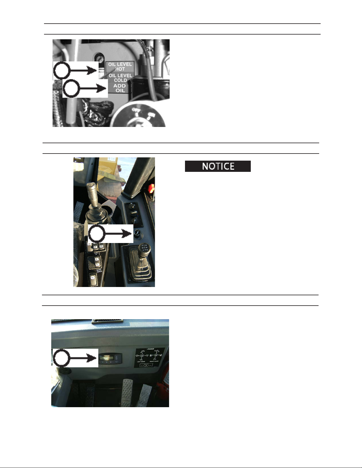
CONTROLS AND INSTRUMENTS
HYDRAULIC RESERVOIR SIGHT GAUGE
The hydraulic reservoir sight gauge is located in the
LH engine compartment.
Do not overll or operate machine with hydrualic oil
level above level indicated (A).
A
Do not operate machine with hydraulic oil level below
add oil indicator (B).
B
146.05
IGNITION SWITCH
Parking brake must be en-
gaged before engine will start.
Shut door.
Turn key in ignition switch (A) clockwise to start machine. Release key when engine starts.
Turn key OFF to shut engine down.
When key is in IGN position, electrical components
A
have power.
When leaving machine, be sure ignition switch is in
OFF position, and remove key. Doing so will prevent
drain on battery.
IQAN®
The IQAN® (A) system is a computer-based control system that delivers precision control through the valving
system. IQAN®’s menus control machine function and
aid in troubleshooting.
A
2546/2548 T3
0108 REAR CON SOLE
516
1108
Page 73
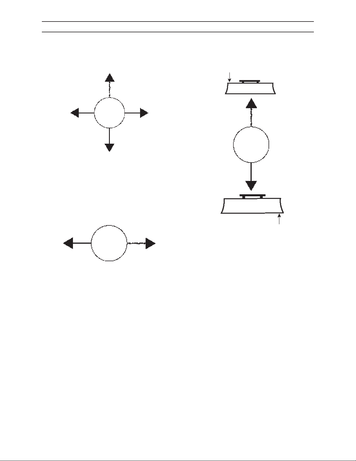
CONTROLS AND INSTRUMENTS
JOYSTICK FUNCTIONS FORWARD BLADE FACING
Left Hand Joystick Right Hand Joystick
BLADE DOWN
Steering Left Hand Joystick
MACHINE
LEFT
LEFT HAND JOYSTICK
This joystick is disabled when seat is in forward (blade)
facing direction.
STEERING LEFT HAND JOYSTICK
Turn Machine Left - Move joystick left.
BLADE UP
MACHINE
RIGHT
RIGHT HAND JOYSTICK
Blade Down - Push joystick forward.
Blade Up - Pull joystick back.
Neutral - When released, joystick returns to neutral
(center) position.
Turn Machine Right - Move joystick right.
2546/2548 T3
517
1108
Page 74
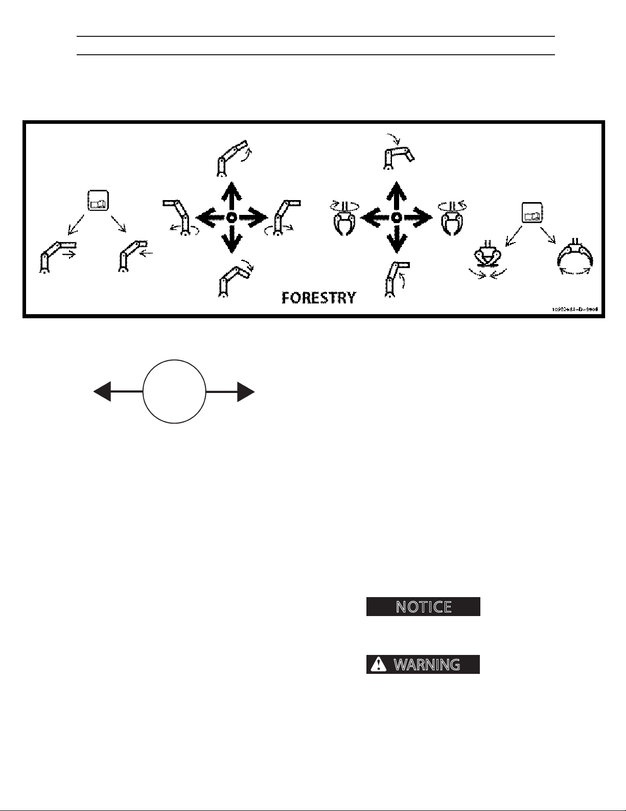
CONTROLS AND INSTRUMENTS
NOTICE
WARNING
FORESTRY JOYSTICK FUNCTIONS REAR BOOM FACING
Left Hand Joystick Right Hand Joystick
MACHINE
LEFT
LEFT HAND JOYSTICK
Main Boom Down - Push joystick forward.
Main Boom Up - Pull joystick back.
Swing CCW- Move joystick left to swing upper structure left.
Swing CW - Move joystick right to swing upper structure right.
Neutral - When released, joystick returns to neutral
(center) position.
STEERING LEFT HAND JOYSTICK
Turn Machine Left - Move joystick left.
Turn Machine Right - Move joystick right.
MACHINE
RIGHT
RIGHT HAND JOYSTICK
Stick Boom Down - Push joystick forward.
Stick Boom Up - Pull joystick back.
Grapple Clockwise - Move joystick left.
Grapple Counterclockwise - Move joystick right.
Neutral - When released, joystick returns to neutral
(center) position.
Recommended RPM while
utilizing boom functions is 1400-1600 RPM.
DO NOT exceed 1800
RPM while utilizing boom functions. If boom is
operated at excessive RPM level, machine system
damage, severe personal injury or death could occur.
2546/2548 T3
518
1108
Page 75
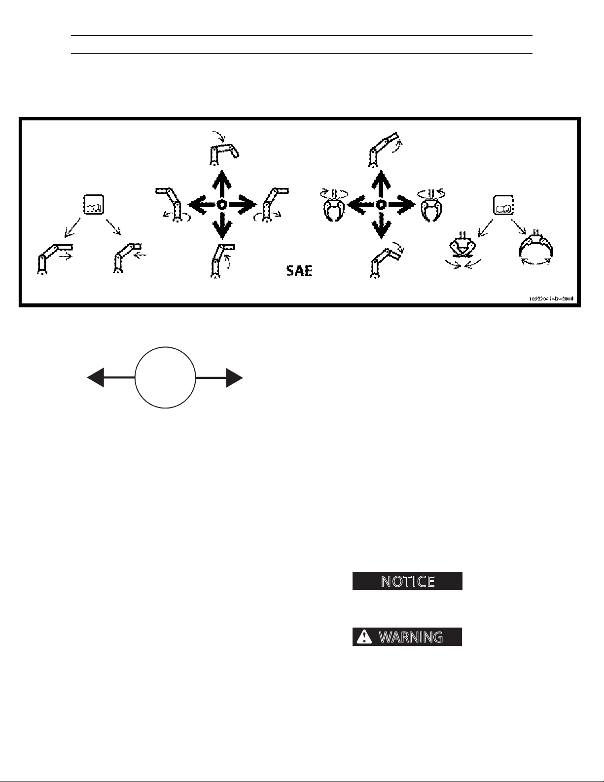
CONTROLS AND INSTRUMENTS
NOTICE
WARNING
SAE JOYSTICK FUNCTIONS REAR BOOM FACING
Left Hand Joystick Right Hand Joystick
MACHINE
LEFT
LEFT HAND JOYSTICK
Stick Boom Down - Push joystick forward.
Stick Boom Up - Pull joystick back.
Swing CCW- Move joystick left to swing upper structure left.
Swing CW - Move joystick right to swing upper structure right.
Neutral - When released, joystick returns to neutral
(center) position.
STEERING LEFT HAND JOYSTICK
Turn Machine Left - Move joystick left.
Turn Machine Right - Move joystick right.
MACHINE
RIGHT
RIGHT HAND JOYSTICK
Main Boom Down - Push joystick forward.
Main Boom Up - Pull joystick back.
Grapple Clockwise - Move joystick left.
Grapple Counterclockwise - Move joystick right.
Neutral - When released, joystick returns to neutral
(center) position.
Recommended RPM while
utilizing boom functions is 1400-1600 RPM.
DO NOT exceed 1800
RPM while utilizing boom functions. If boom is
operated at excessive RPM level, machine system
damage, severe personal injury or death could occur.
2546/2548 T3
519
1108
Page 76
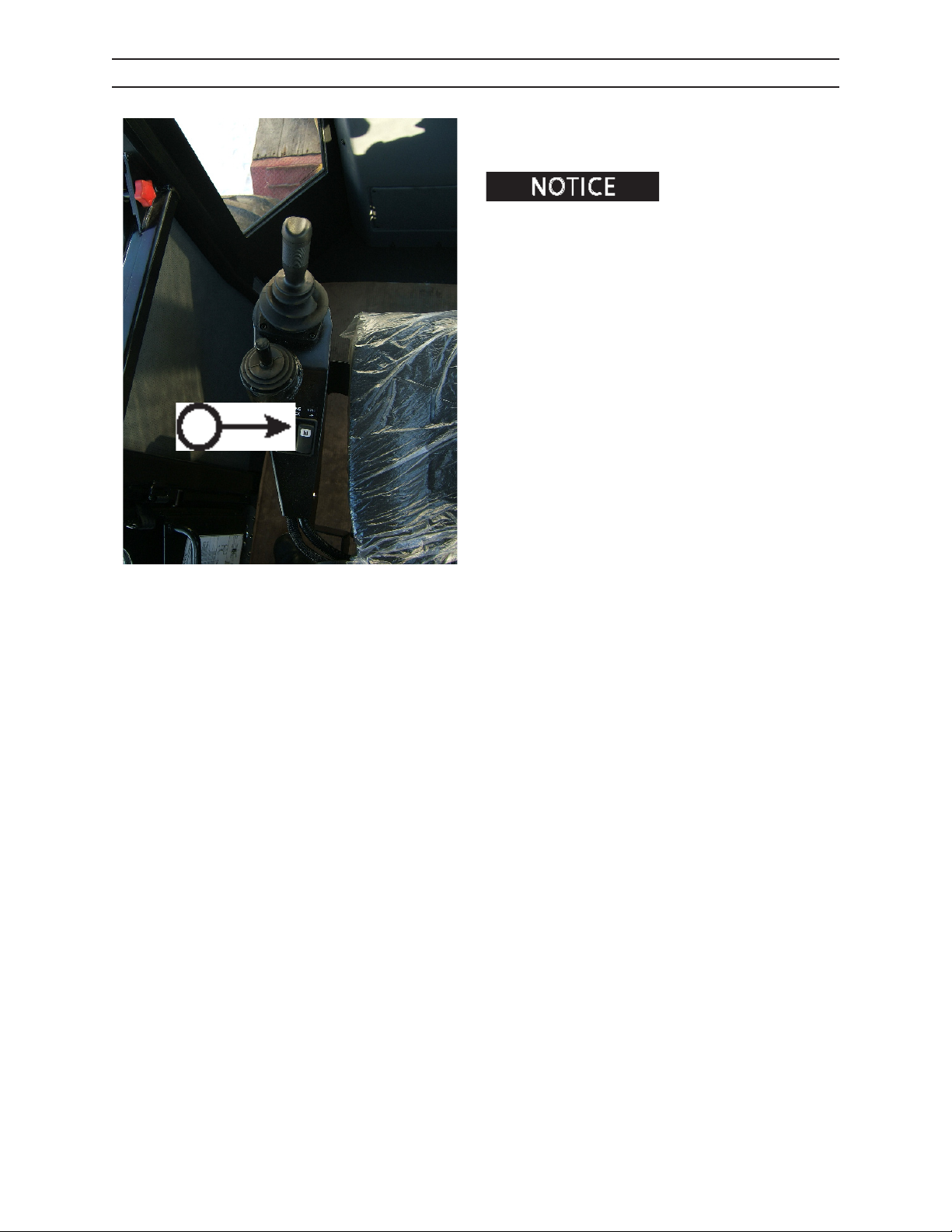
A
CONTROLS AND INSTRUMENTS
LOAD SENSE DUMP SWITCH
1. Depress load sense dump switch (A), located on the
LH side console of the seat, to prevent pressure from
building in the main hydraulic pump.
Load sense dump switch
should only be used under cold weather warm up operation. Refer to cold weather start, Operation Section.
2546/2548 T3
520
1108
Page 77
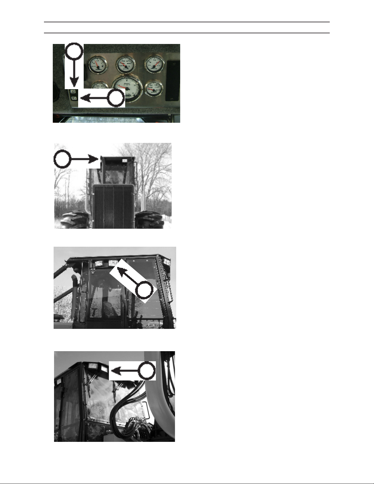
CONTROLS AND INSTRUMENTS
OPERATING LIGHTS SWITCHES
B
OPERATING LIGHTS
Depress switches to activate desired work light lamps.
A - Drive lamps
B - Load Lamps
A
0108 GAUGE PANEL
A - Drive lamps
A
127.05
A - Drive lamps
A
168.05
B - Load Lamps
B
2546/2548 T3
169.05
521
1108
Page 78
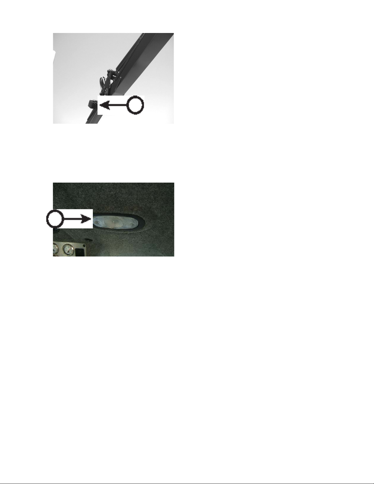
CONTROLS AND INSTRUMENTS
OPERATING LIGHTS SWITCHES
B - Load Lamps
B
524.45
DOME LIGHT
Depress front of lens (C) to turn dome light on.
Depress rear of lens (C) to turn dome light o.
C
0108 DOME
2546/2548 T3
522
1108
Page 79
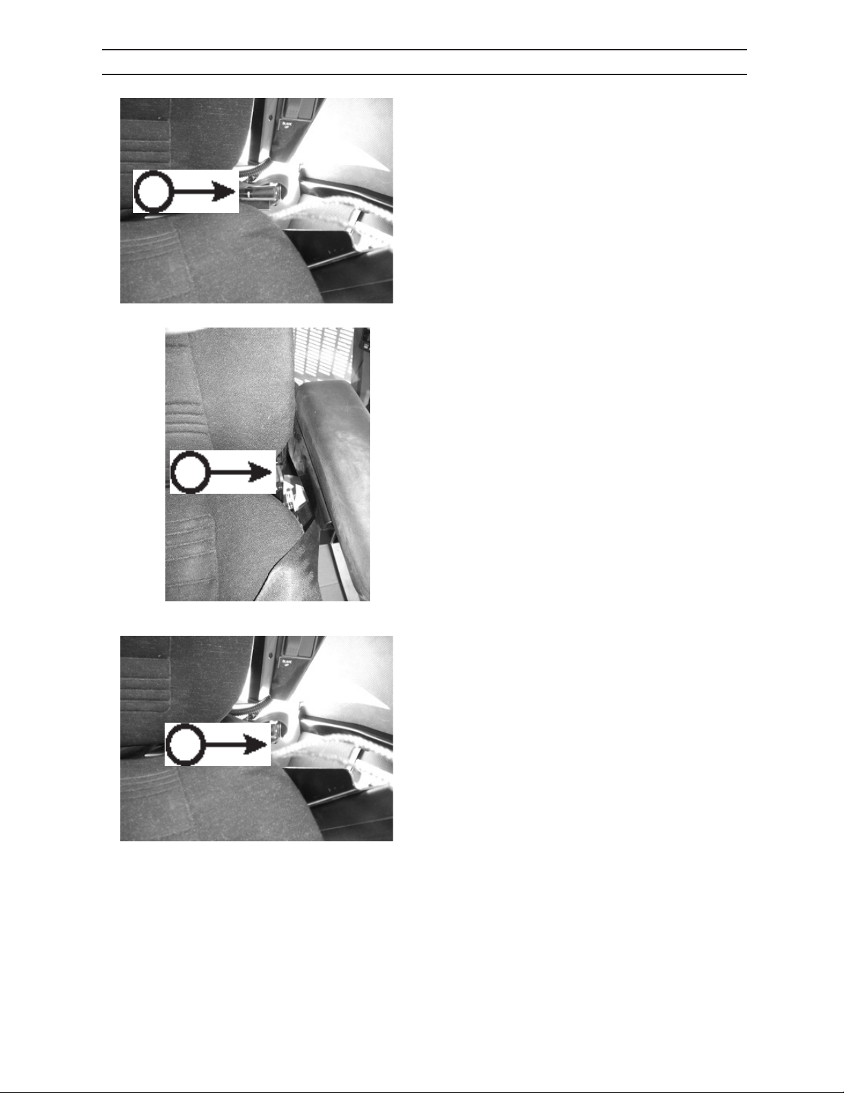
A
CONTROLS AND INSTRUMENTS
OPERATOR’S SEAT
Adjust operator’s seat using the following instructions.
SEAT WEIGHT ADJUSTMENT
While seated, adjust seat using the + - adjuster lever
(A - on LH of seat) until indicator tongue (B - on RH of
seat) is paralell with seat back.
524158
C
B
52462
BACK REST ANGLE ADJUSTMENT
While seated with back rmly against back rest, depress lever (C) on either side of seat to adjust angle of
back rest.
524158
2546/2548 T3
523
1108
Page 80
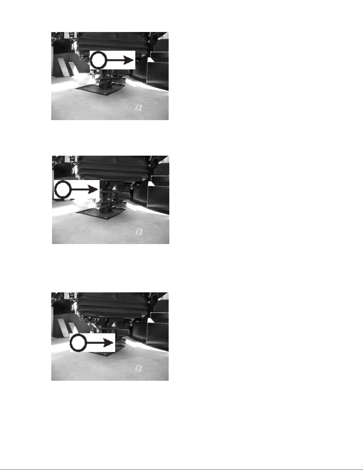
A
CONTROLS AND INSTRUMENTS
OPERATOR’S SEAT
FRONT AND REAR ADJUSTMENT
While seated, move lever (A) inward and move seat
forward or backward to required position and release.
52457
SEAT CUSHION ADJUSTMENT
To adjust the front of seat cushion, pull latch (B) upwards and lift into one of four settings.
B
To adjust the rear of seat cushion, push on seat
cushion and set into one of three settings (notches)
provided.
52457
SEAT DIRECTION ADJUSTMENT
To turn seat forward (blade) and backward (boom),
depress lever (C).
While seated, turn seat to desired position.
Seat will lock into place.
C
2546/2548 T3
52457
524
1108
Page 81
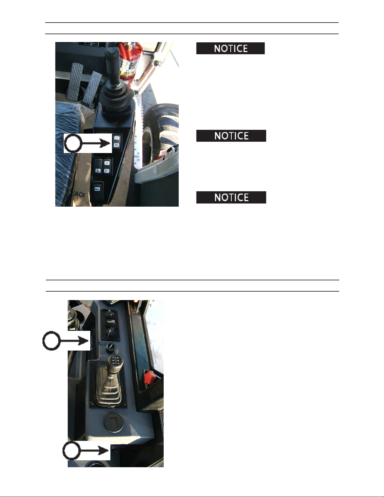
CONTROLS AND INSTRUMENTS
PARK BRAKE
pelled with Park Brake switch on, your system has
failed. Shut down machine and contact your authorized representative.
1. Depress top of park brake switch (A) to
activate (set) park brake.
2. Verify that park brake indicator is illuminated.
3. Depress bottom of park brake switch to deactivate
(release) park brake (A).
If machine can be pro-
A
Come to a complete stop
before applying park brake.
With park brake switch in “on” position, park brakes will
be applied as the machine comes to a stop.
With park brake switch in “o” position, park brakes
will not apply while engine is running.
Park brake switch should be
left in the “on” position while operating loader functions.
Turn park brake switch to “o” position when not
utilizing loader functions.
POWER OUTLETS
Two 12 volt, 15 amp power outlets (A) are provided for
electrically powered accessories.
A
2546/2548 T3
A
0108 TRANS CON TROL
To protect batteries against accidental discharge,
outlets provide power only when key switch is turned
to IGN or ACC.
525
1108
Page 82
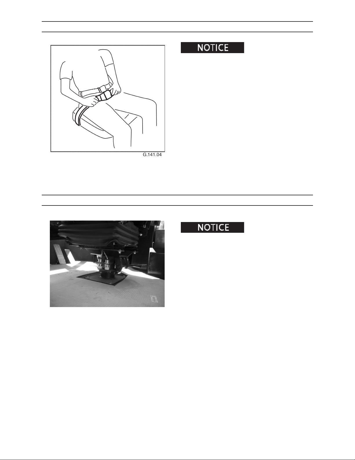
CONTROLS AND INSTRUMENTS
SEAT BELT
can cause severe personal injury or death.
To reduce the risk of personal injury resulting from a
roll over or sudden stop, always wear a seat belt fastened snugly when operating this machine.
This machine can change directions rapidly. It can start
and stop quickly. See Operation section, for instructions on properly using the seat belt.
To fasten seat belt, adjust operator’s seat to a comfortable position. Adjust the belt so that it ts snugly.
A roll over or sudden stop
SEAT PROXIMITY SWITCH
locked in either forward (blade) facing position or rear
(boom) facing position. All controls will be disabled if seat
is not locked into position.
Lock operator’s seat into either forward (blade) or rear
(boom) facing position.
524.63
Operator’s seat must be
2546/2548 T3
526
1108
Page 83
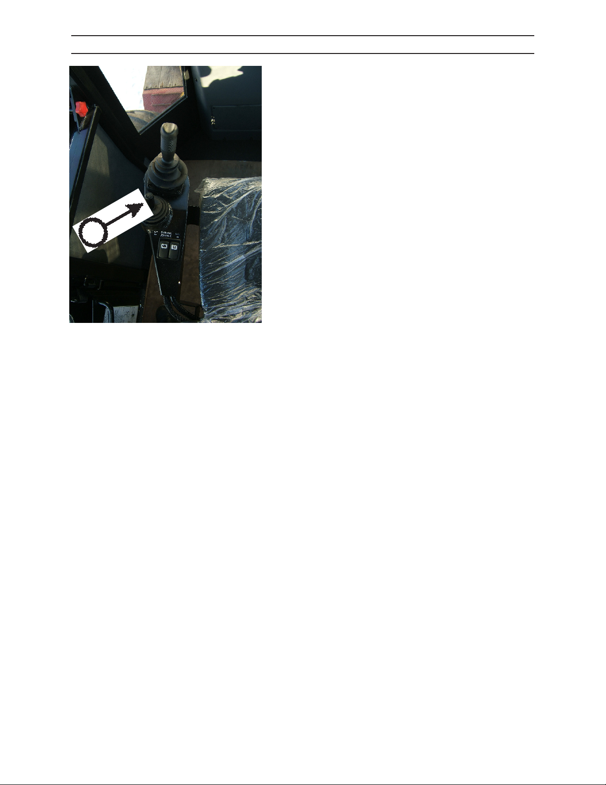
A
CONTROLS AND INSTRUMENTS
STEERING DEFAULT
When facing forward (blade) or facing rear (boom):
1. With machine in motion, it can be steered by
moving the steering joystick (A) in the direction
desired.
2546/2548 T3
527
1108
Page 84
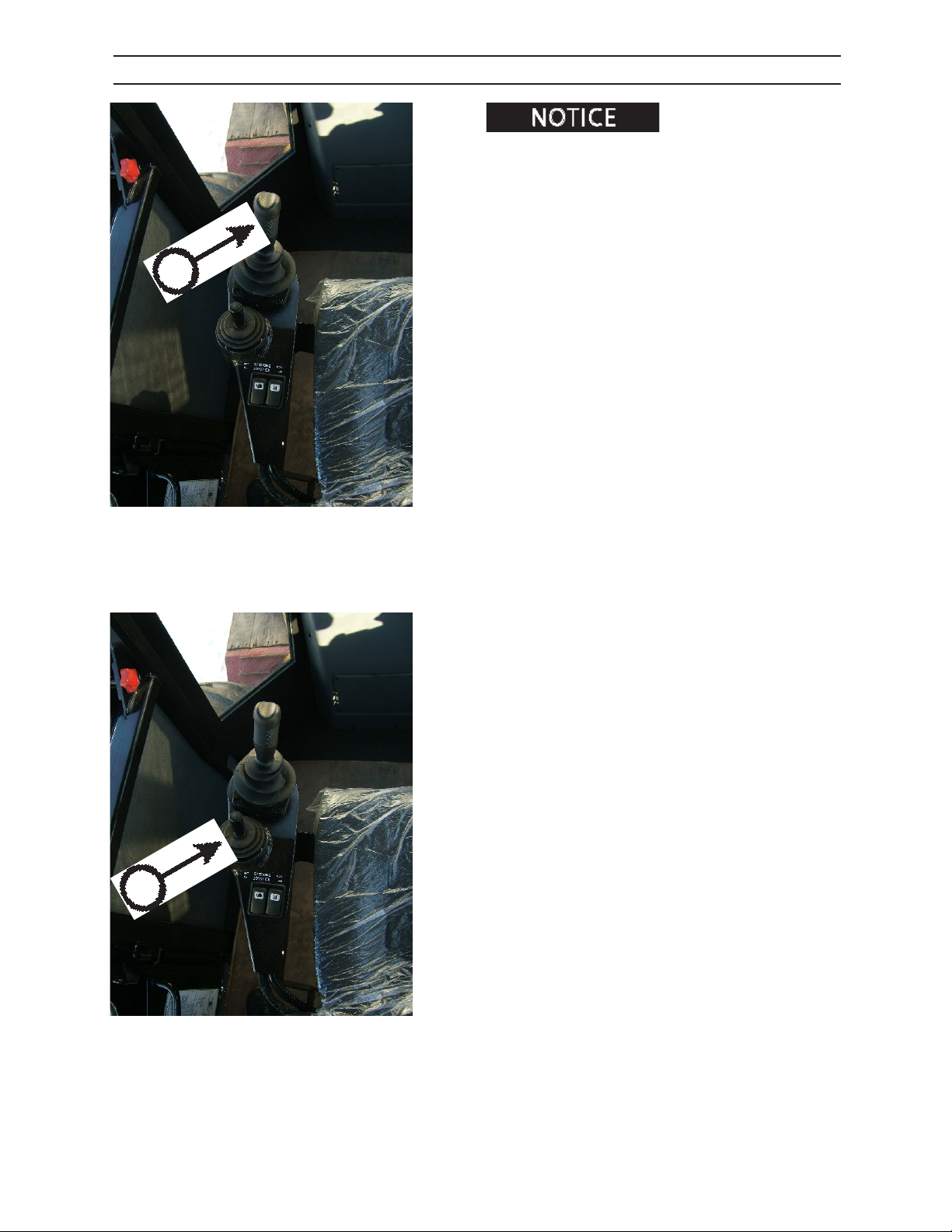
A
CONTROLS AND INSTRUMENTS
STEERING OPTIONAL
The optional steering can
be selected throught the Iqan program. Refer to the
Iqan section in this manual.
When facing forward (blade):
1. With machine in motion, it can be steered by
moving the main joystick (A) in the direction
desired.
B
When facing rear (boom):
2. With machine in motion, it can be steered by
moving the steering joystick (B) in the direction
desired.
2546/2548 T3
528
1108
Page 85
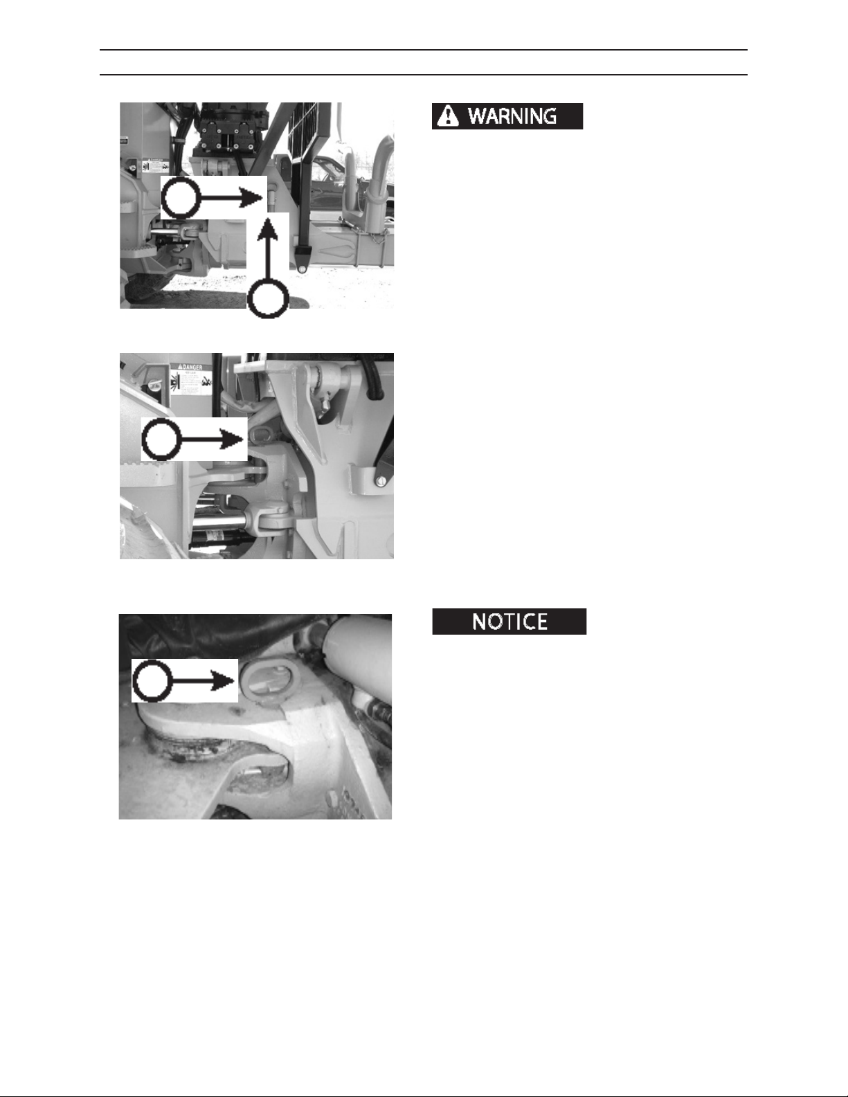
CONTROLS AND INSTRUMENTS
STEERING LOCK
Steering lock must be
in use BEFORE performing service. Failure to use
steering lock could result in unexpected movement of the forwarder. If steering is activated with
A
a person in center hinge “crush point” area, severe
personal injury or death could occur.
INSTALLING LOCK
1. Remove locking clip (A).
D
B
2. Remove steering lock pin from storage location
0108
(B).
3. Align front and rear frame. Place pin through hole
(C).
C
524.08
REMOVING LOCK
Be sure to place steering lock
pin in storage location before driving forwarder.
1. Remove locking pin from hole (D) in front and
rear frame.
2546/2548 T3
2. Place in storage location. Secure with locking clip.
180.05
529
1108
Page 86
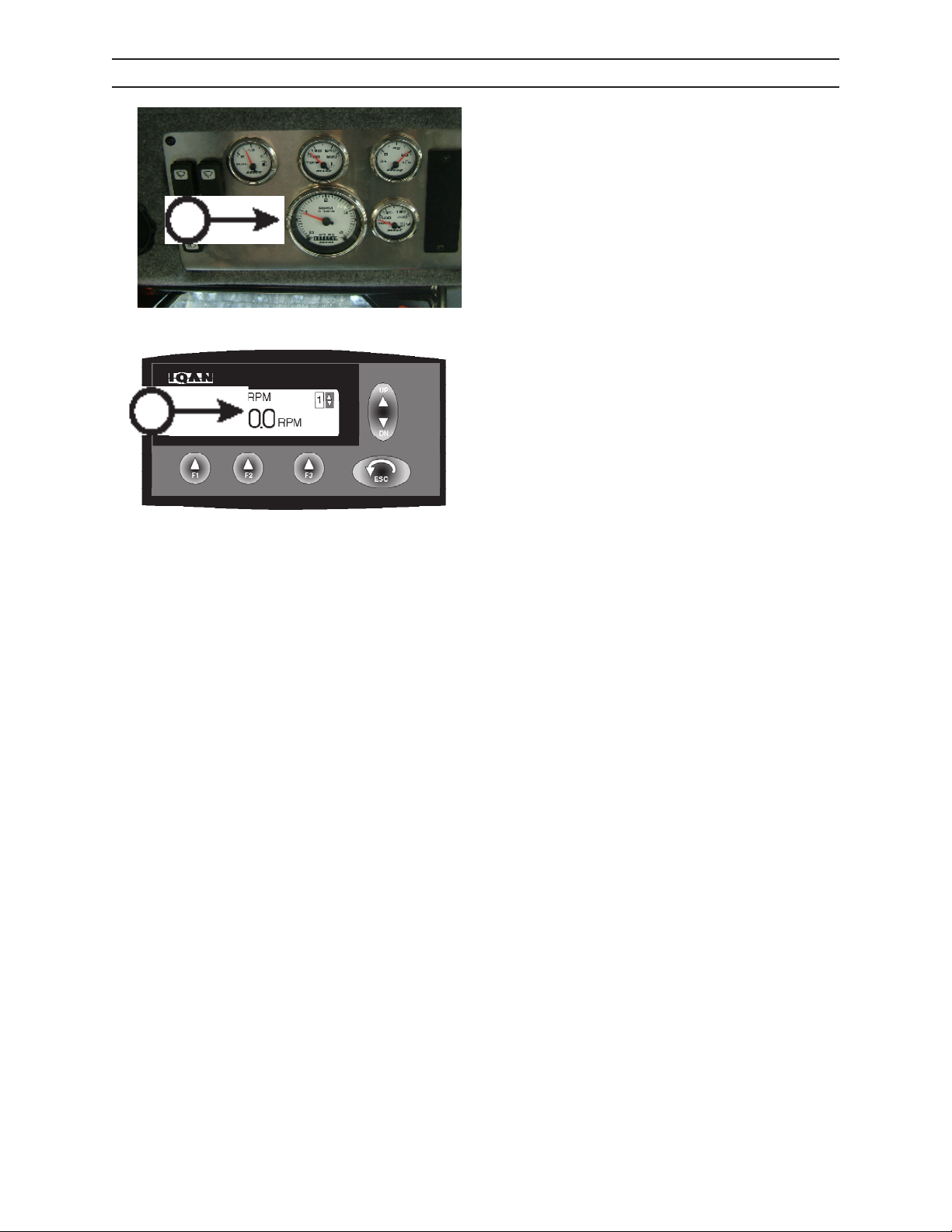
B
CONTROLS AND INSTRUMENTS
TACHOMETER
The tachometer (A) registers the engine speed in
hundreds of revolutions per minute (RPM). This is
displayed through a gauge (A) in the forward (blade)
facing position and through the IQAN® (B) in the rear
(boom) facing position.
A
0108 GAUGE PANEL
IQAN.44
2546/2548 T3
530
1108
Page 87
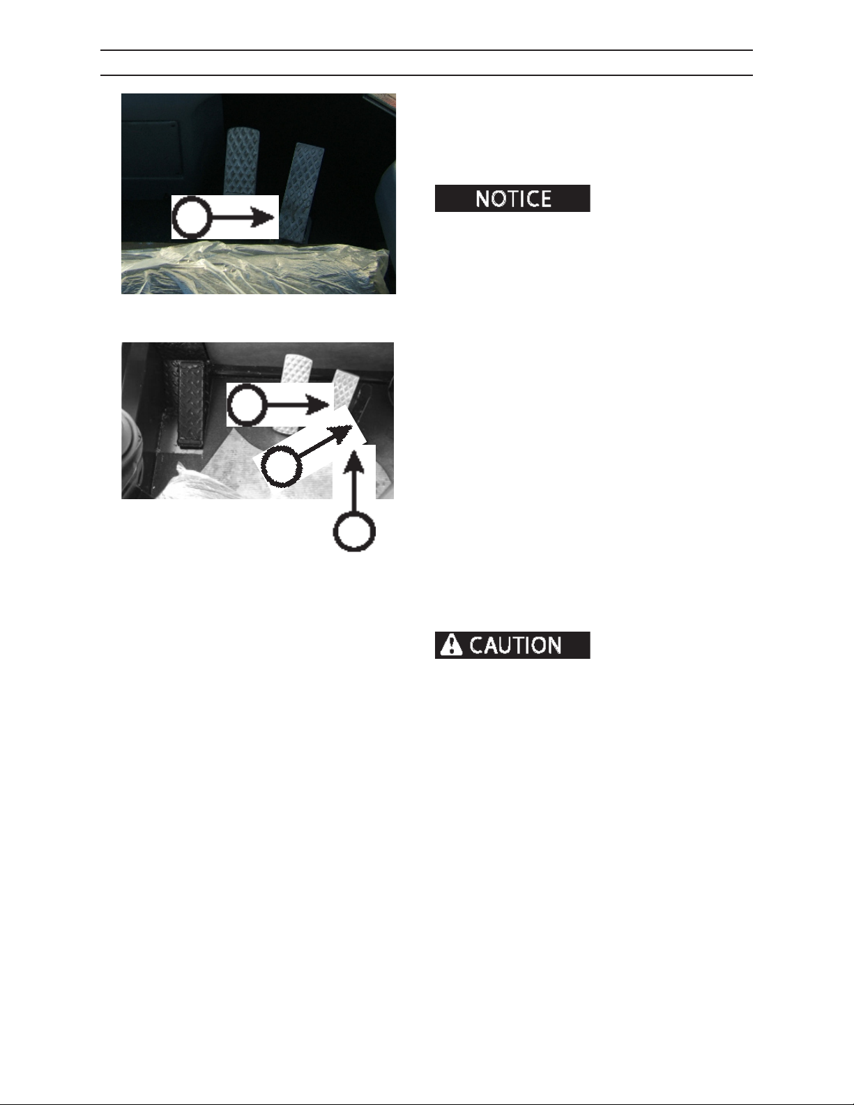
CONTROLS AND INSTRUMENTS
THROTTLE
The throttle (A) controls engine speed from low idle to
full governed speed as follows:
Low idle rpm 1000
Full load governed rpm 2700
A
A
B
C
0108 FRONT
075.05
There are two throttle pedals
on the forwarder, one in the front (blade) facing position
and one in the rear (boom) facing position.
INCREASING ENGINE SPEED
Depress the throttle pedal (A) to increase engine
speed. With seat in rear facing (boom) position, the
throttle lock (B) can be depressed, locking throttle at
desired engine speed.
DECREASING ENGINE SPEED
WHEN FACING FORWARD BLADE:
Remove pressure from throttle pedal to decrease
engine speed.
WHEN FACING REAR BOOM:
Remove pressure from throttle pedal to decrease
engine speed.
If throttle lock (B) is engaged, depress throttle lock
release (C) and remove pressure from throttle pedal to
decrease engine speed.
2546/2548 T3
When seat is in rear facing
position (boom), there is a throttle lock available.
Verify that throttle lock is disengaged before rotating seat to front facing (blade) position.
531
1108
Page 88
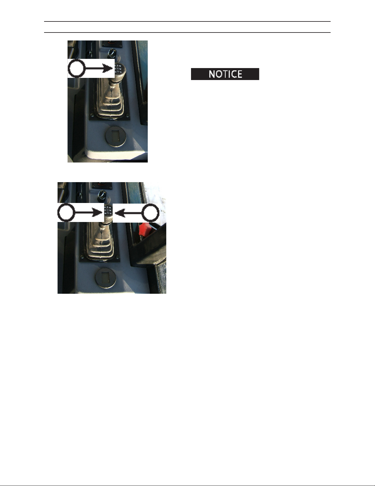
A
CONTROLS AND INSTRUMENTS
TRANSMISSION CONTROLS
The transmission console has a bump shift lever (A) to
allow changing of gears. The switch (B) to arm the foot
shift pedal.
When the foot shift switch is
armed, the bump shift transmission control is disarmed.
WHEN OPERATOR’S SEAT IS LOCKED IN FRONT
BLADE FACING POSITION:
The transmission is shifted into forward by pushing
bump shift lever (A) forward. The transmission is shifted into reverse by moving bump shift lever backward.
The transmission is shifted to higher gears by moving
the shift lever in the direction of the rabbit (B).
C
B
The transmission is shifted to lower gears by moving
the shift lever in the direction of the turtle (C).
2546/2548 T3
532
1108
Page 89
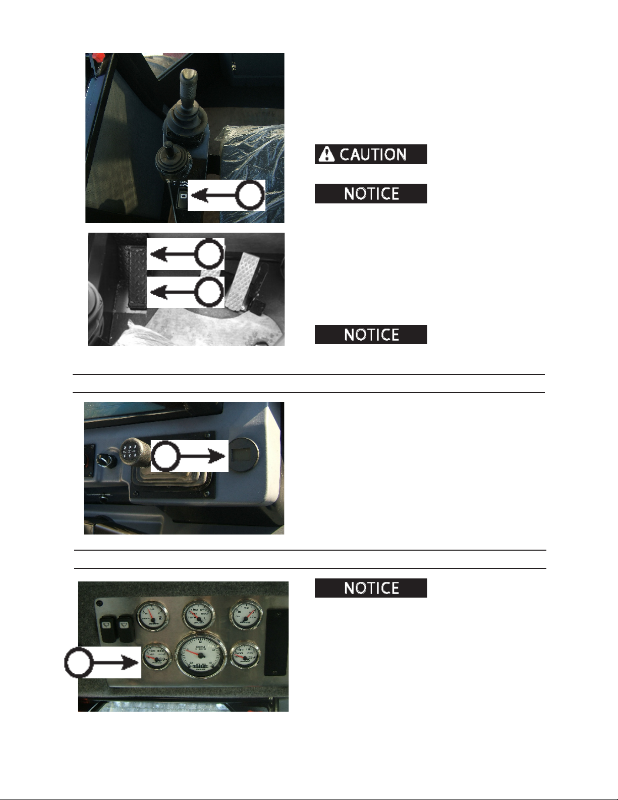
CONTROLS AND INSTRUMENTS
WHEN OPERATOR’S SEAT IS LOCKED IN REAR
BOOM FACING POSITION:
H
G
The transmission is shifted to higher gears by
the shift lever in the direction of the rabbit (D).
The transmission is shifted to lower gears by
shift lever in the direction of the turtle (E).
Apply parking brake before arming foot shifter switch.
F
armed, the bump shift transmission control is disarmed.
When operator’s seat is locked in rear (boom) facing
position with foot shift activation switch (F) armed (depressed):
The transmission is shifted into low forward gear by applying pressure to the heel end of the foot shift pedal (G).
The transmission is shifted into low reverse gear by applying pressure to the toe end of the foot shift pedal (H).
075.05
armed, transmission can only be shifted into low gears.
When the foot shift switch is
When foot shift pedal is
moving
moving
the
A
TRANSMISSION DISPLAY PANEL
The transmission display panel (A) displays which gear
the transmission is in and provides diagnostic codes
for troubleshooting.
A
0108 TRANS CON TROL
TRANSMISSION OIL TEMPERATURE GAUGE
Possible transmission system
damage can occur if operating for an extended period of
time above 250° F (116°C).
Transmission oil temperature gauge displays
Normal hydraulic operating temperature is 200°F
(116°C).
2546/2548 T3
0108 GAUGE PANEL
The transmission oil temperature gauge (A) monitors
the transmission oil temperature.
Normal transmission oil operating temperature is
200°F (116°C). If the transmission temperature gauge
exceeds 240°F (116°C) an alarm will sound.
533
1108
Page 90
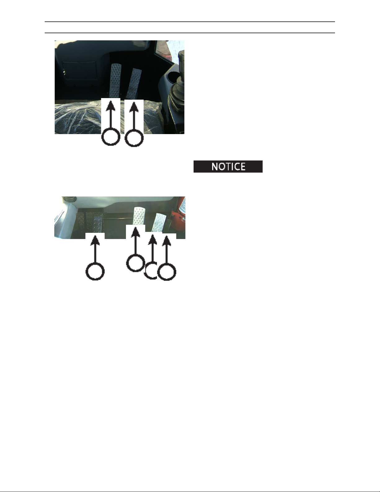
CONTROLS AND INSTRUMENTS
PEDALS
WHEN FACING FORWARD BLADE:
Left pedal - controls the brake.
Right pedal - controls the throttle function.
A. Left Pedal
B. Right Pedal
Brake operation - Push toe end of left pedall (A) down.
Machine will slow, coming to complete stop.
Increase engine speed - Push toe end of right (throttle)
pedal (B) down. Engine speed will increase.
A
A
B
B
C
0108 FRONT
D
Decrease engine speed - Remove pressure from
throttle pedal to decrease engine speed.
When seat is in rear facing
position, the throttle lock is available. Verify that throttle
lock is disengaged before rotating seat to front facing
position.
WHEN FACING REAR BOOM:
Left pedal - controls the foot shifting function.
Center pedal - controls the brake.
Right pedal - controls the throttle function.
Throttle lock pedal - locks the throttle postiion.
A. Left Pedal
B. Center Pedal
C. Right Pedal
D. Throttle Lock Pedal
PEDAL OPERATION
2546/2548 T3
Reverse travel (with foot shift switch armed) - Push toe
end of left pedal (A) down. Machine will travel in
reverse (blade direction) in low gear.
Forward travel (with foot shift switch armed) - Push
heel end of left pedal (A) down. Machine will travel
forward (boom direction) in low gear.
Brake operation - Push toe end of center pedal (B)
down. Machine will slow, coming to complete
stop.
Increase engine speed - Push toe end of right pedal (C)
down. Engine speed will increase.
Decrease engine speed - Remove pressure from
throttle pedal to decrease engine speed.
Throttle lock -Push toe end of throttle lock pedal (D)
down simultaneously with throttle pedal. Will hold
desired engine speed.
534
1108
Page 91
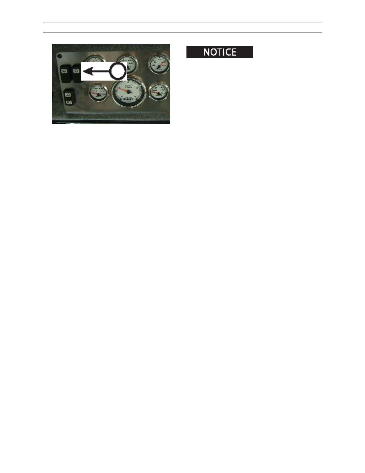
A
CONTROLS AND INSTRUMENTS
WINDSHIELD WIPER
Operating windshield wipers
on a dry window will scratch the window.
Turn wiper switch (A) to activate wiper at low or high
speed.
The wiper blade will return to its stored location when
switch is in the OFF position.
0108 GAUGE PANEL
2546/2548 T3
535
1108
Page 92

CONTROLS AND INSTRUMENTS
2546/2548 T3
536
1108
Page 93
PRESTART INSPECTION
WARNING
WARNING
NOTICE
PRESTART INSPECTION
Do not use this machine until you read, study and understand this manual and
learn how to properly operate this machine. Operating this machine without reading, studying, and understanding this manual could result in severe personal injury or death.
Failure to perform a daily inspection of the machine could result in machine
damage and severe personal injury.
Inspector’s Initials
Machine Serial NumberDate of Inspection
PRESTART CHECKS: ON THE GROUND
Check fuel level; add fuel if necessary.
Check engine oil level; add engine oil if necessary.
Check radiator coolant level. Add proper coolant mixture if necessary. Clean radiator of debris.
Check air cleaner. Clean or replace air cleaner lter if necessary.
Check for protective clothing (wear it) and safety equipment (know where it is).
Check entire machine by performing a thorough walk-around inspection.
Check for loose or missing parts. Tighten loose parts. Replace any missing parts.
Check hydraulic hoses and lines for wear and/or damage. Replace any defective hoses and/or lines.
Check that machine has been properly lubricated as spelled out in the Scheduled/Periodic Maintenance
Services section of this manual.
Check shields and guards. They must be in place and undamaged.
Check that safety decals are on machine and that they are readable.
Check that shut-o valves are open.
Check that battery disconnect switches are on.
Check for dirt and grime on all hydraulic components. Clean away dirt and grime to help prevent overheating.
Check for ice, snow, oil, grease and debris on steps and walkways. Clear away ice, snow, oil, grease or
debris to prevent slips and falls.
Check for any loose skid-resistant mats. Replace mats if they are loose.
Check hydraulic oil reservoir level. Add hydraulic oil to reservoir if necessary.
Check for combustible or ammable materials. Remove them from machine if found.
Check mounting hardware for tightness.
Check that machine will not be near electrical wires. See Operation section, for more information.
Check frame for damage, cracks, debris and other problems. Immediately report any structural problems
(cracks) to an authorized dealer for diagnosis and repair or replacement.
Check that all lights are in working order.
Check electrical system for worn or frayed wires and loose connections. Repair or replace if necessary.
2546/2548 T3
Pages in this section may be copied. Check o each inspection item before operat-
ing machine. File the copy as a record of inspection as required by OSHA or local governing body.
61
1108
Page 94
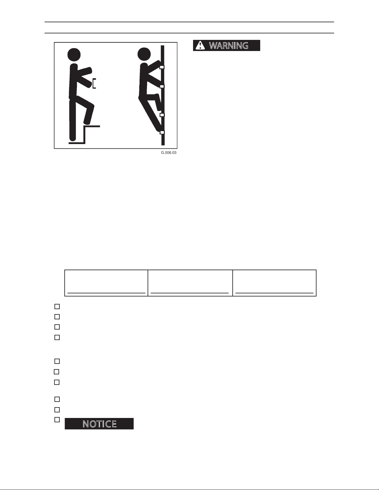
PRESTART INSPECTION
NOTICE
WARNING
PRESTART CHECKS: IN THE CAB
severe personal injury or death.
Use provided hand holds and steps while maintaining at least 3 points of support (1 foot and 2 hands
or 2 feet and 1 hand) when getting on and o machine. Face machine when getting on and
o of it.
Never use controls as hand holds. Never use steering wheel as a hand hold. Moving the steering
wheel from its center position will COMPLETELY
turn machine right or left.
DO NOT mount machine if hand rails or steps are
broken or missing. Get them repaired rst.
DO NOT jump on or o machine unless it has
touched a live electrical wire and it must be exited.
Ensure rm foot position when getting on and o
machine. Be careful of slippery conditions on platform, steps, and hand holds when getting on and
o machine.
Slips and falls can cause
Remove oil, grease, mud, ice, etc. before mounting
or dismounting machine.
To prevent slips and falls, replace skid-resistant
material if it is worn, damaged or missing.
Inspector’s Initials
Check that there is no mud or debris on cab oor.
Check for free movement of controls.
Check that safety decals are present and can be clearly read.
Check that all cab polycarbonate windows are clean and clear. Replace any damaged polycarbonate
material. See Scheduled and Periodic Maintenance section for more information.
Check that seat belt works properly. Replace worn or damaged seat belt .
Check that re extinguisher is adequately charged.
Check instrument panel for broken gauges and/or broken indicator lights. Have gauges and/or indicator
lights repaired if necessary.
Check fuel to be sure machine has enough fuel. Refuel machine if necessary.
Check window emergency exits. All emergency exit levers should be present and operate freely.
Check that all items in cab that are not part of the machine such as lunch boxes or tools, are secured.
Machine Serial NumberDate of Inspection
2546/2548 T3
Pages in this section may be copied. Check o each inspection item before operat-
ing machine. File the copy as a record of inspection as required by OSHA or local governing body.
62
1108
Page 95
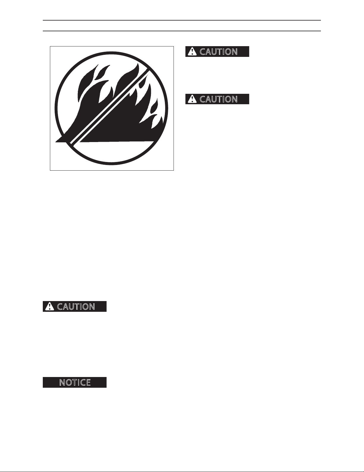
PRESTART INSPECTION
CAUTION
CAUTION
CAUTION
NOTICE
FIRE PREVENTION
Fires can cause personal
injury or machine damage.
Keep machine clean. Remove debris, especially from
heat sources. Fire prevention beats re ghting. Hourly
or daily inspections can reduce the possibility of res.
Forest debris can collect
on the machine and cause a re. When forest debris
mixes with ammable uids in a hot, conned space,
the risk of a re starting greatly increases. KEEP THE
MACHINE CLEAN.
Check machine daily for re hazards. Remove debris from areas of the machine that create heat and that are
potential re start points. Depending of machine model, check for ammable debris in the following locations:
• Engine block • Turbocharger
• Exhaust manifold • Battery
• Electrical connections • Control valves
Fire needs fuel. Remove combustible material (fuel for re) from heat sources. Keep the machine clean. Remove
the following material from areas of the machine that create heat:
• Pine needles • Twigs • Debris
• Shop rags • Oil spills • Coolant Mixture
• Leaves • Sticks
• Grease • Bark
• Sawdust • Diesel fuel
Keep the machine clean. Risk of re increases if combustible materials and amma-
ble materials build up on machine. This machine was not designed to house or store combustible materials.
Regularly remove ammable materials (such as diesel fuel, engine oil, hydraulic oil and grease) from all areas of
the machine. Clean up after working. Keep the fuel and hydraulic systems in good repair.
Check hydraulic hoses, fuel lines and ttings for leaks. Tighten loose ttings. If hoses or lines are bent, kinked or
show signs of wear, install new parts. Check electrical connections to be sure they are clean and secure.
Frayed or worn insulation on battery cable or other wires may lead to electrical res. Check cable and wires and
replace if insulation is frayed, worn or damaged.
the engine to ensure there is no forest debris/trash re start up. Keep a re extinguisher ready during this 30 minute
cool down.
2546/2548 T3
At the end of each shift ALWAYS stay with the machine for 30 minutes after shutting down
0808
63
1108
Page 96
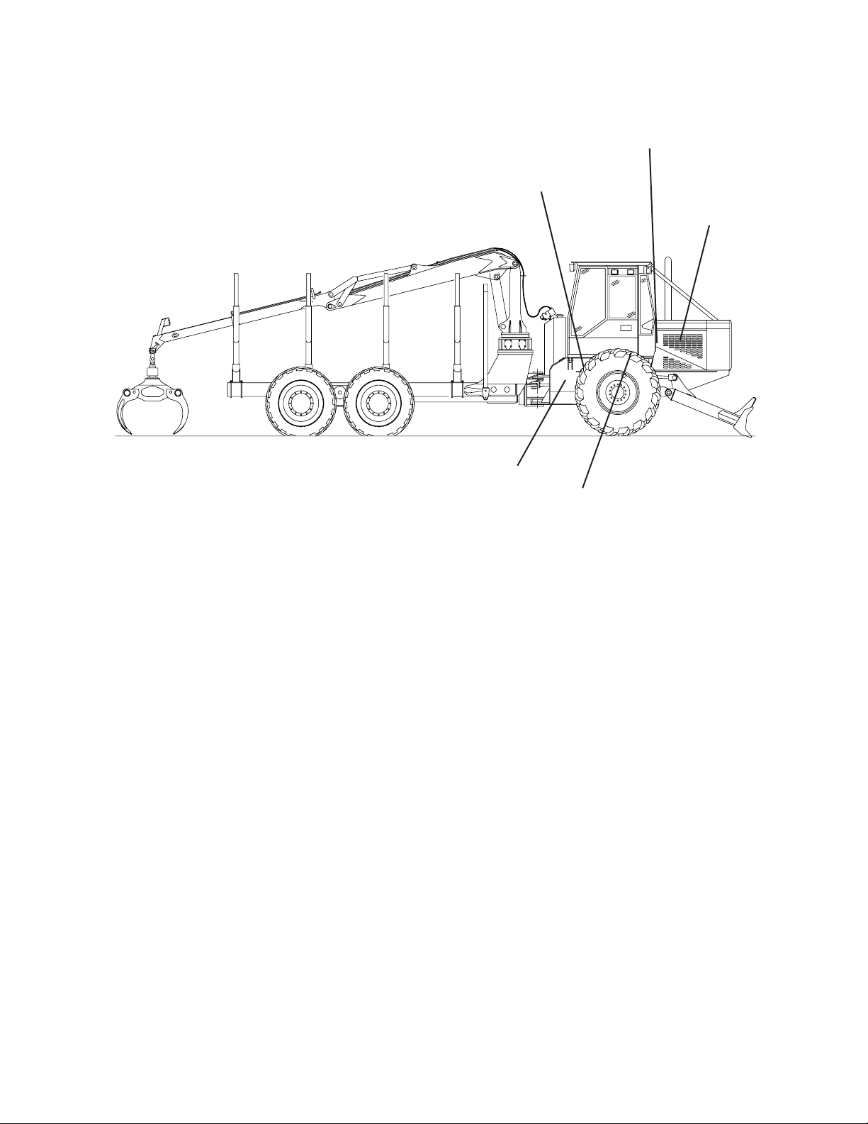
PRESTART INSPECTION
WHERE ARE FIRES MOST LIKELY TO START?
Fires can start almost anywhere on a logging vehicle.
Here are some locations susceptible to re.
Electrical
Connections
Battery Box
Transmission
Exhaust Manifold
Engine Block
Turbocharger
Hydraulic Hoses
and Controls
2546/2548 T3
64
1108
Page 97
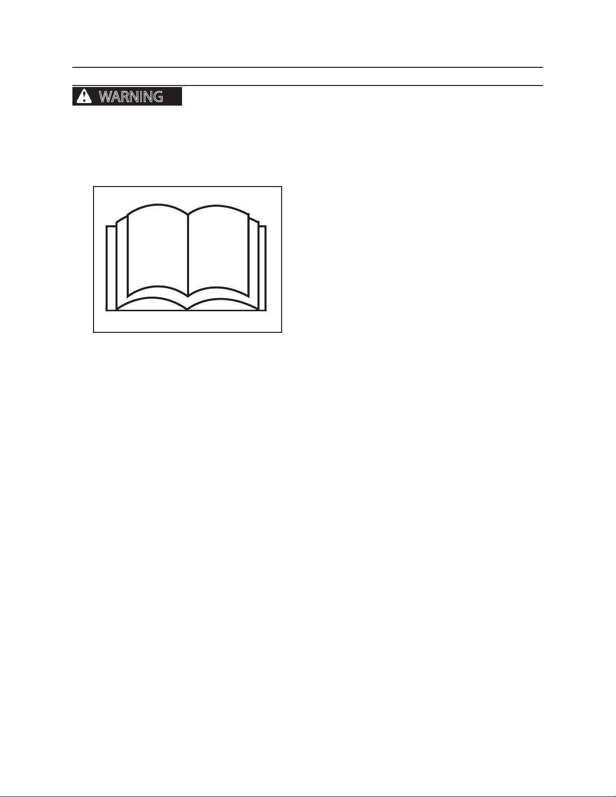
OPERATION
WARNING
OPERATION
GENERAL GUIDELINES
Only a trained, qualied, and authorized operator shall be allowed to operate
this machine. Only use this machine after you have carefully read this manual and have learned how to
safely operate and maintain this machine. Unsafe operation can cause severe personal injury or death.
OPERATOR PREPARATION
Operator must be fully trained, qualied, and authorized to operate this machine.
Before running this machine, operator must know the
location and purpose of
• controls
• indicator lights
• instruments
• local operating safety rules and procedures
100.05
You must be at least eighteen (18) years old to operate this machine (Code of Federal Regulations: Labor).
Never operate this machine while under the inuence of drugs or alcohol. Use of prescription or over-the-counter drugs or medications requires advice from a medical practitioner on whether or not you can safely operate
this machine.
Do not operate this machine if you are subject to dizziness, seizures, or motion disturbance.
No riders are allowed on this machine. Machine riders can fall from machine or be injured by movement of machinery, causing severe personal injury or death. Do not allow riders on a machine that is operating or moving.
Follow all safety operating instructions and practices. (See General Safety section.)
Keep machine away from power lines.
If this manual is lost, contact your authorized dealer for a new manual. Keep manual in the cab.
Report any noticeable machine problems to people who can repair the problems before machine is used.
Be sure cab windows are clean before operating machine. Cab windows must be clear of ice and frost. Replace
windows that are cracked, yellow, and/or hazy.
Before using this machine on hills or slopes, see information regarding slope operation in this manual.
• safety and instruction decals (see Safety Decals
section)
Remember, you are key to the safe operation of this machine.
2546/2548 T3 1108
71
Page 98
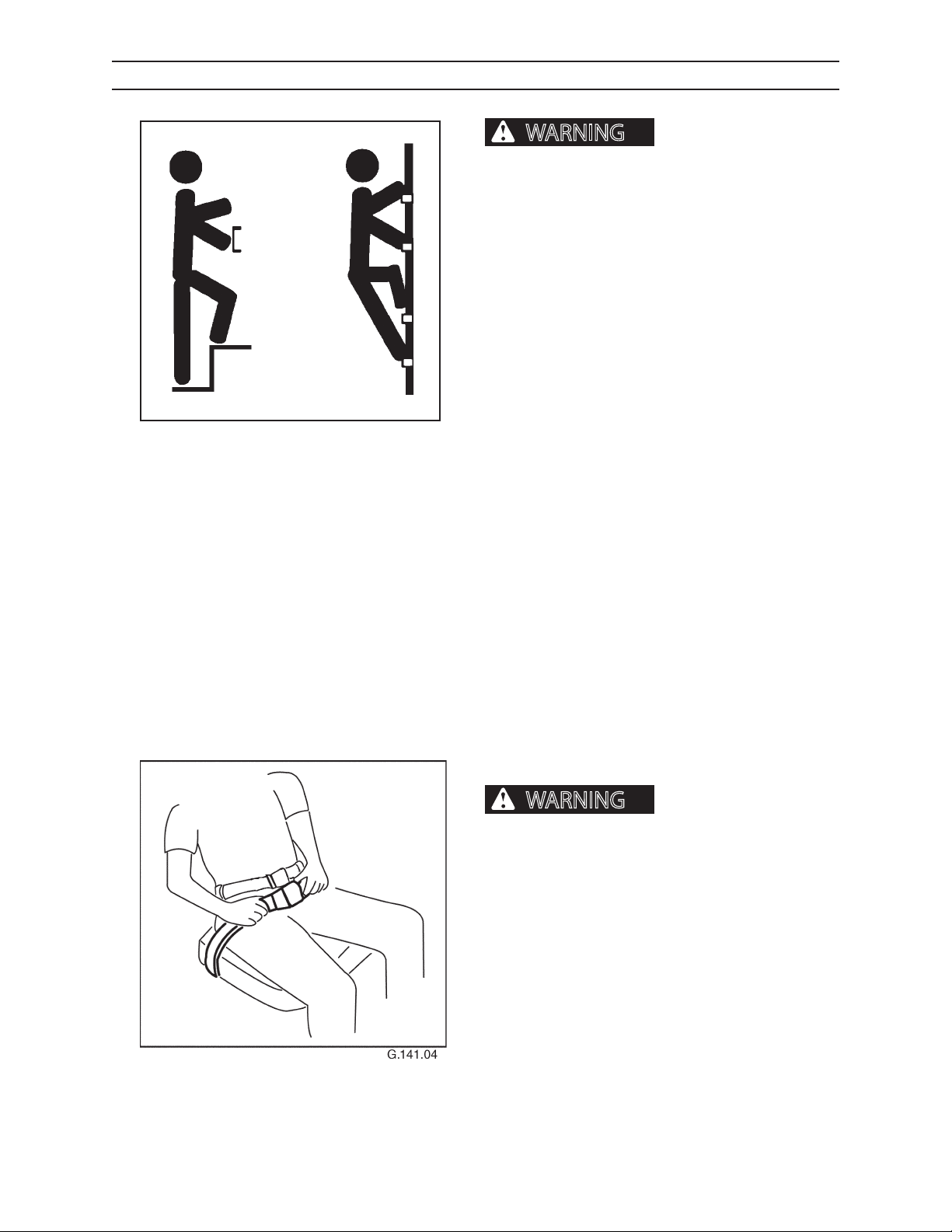
OPERATION
WARNING
WARNING
GETTING ON MACHINE
severe personal injury or death.
Use provided hand holds and steps while maintaining at least 3 points of support (1 foot and 2 hands
or 2 feet and 1 hand) when getting on and o machine. Face machine when getting on and
o of it.
Never use controls as hand holds. Never use steering wheel as a hand hold. Moving the steering
wheel from its center position will COMPLETELY
turn machine right or left.
DO NOT mount machine if hand rails or steps are
broken or missing. Get them repaired rst.
Slips and falls can cause
G.006.02
DO NOT jump on or o machine unless it has
touched a live electrical wire and it must be exited.
Ensure rm foot position when getting on and o
machine. Be careful of slippery conditions on platform, steps, and hand holds when getting on and
o machine.
Remove oil, grease, mud, ice, etc. before mounting
or dismounting machine.
To prevent slips and falls, replace skid-resistant material if it is worn, damaged or missing.
SEAT BELT
A rollover or sudden stop
can cause severe personal injury or death.
Always wear your seat belt, fastened snugly, when operating machine to reduce the risk of personal injury
resulting from a rollover or sudden stop.
2546/2548 T3
72
1108
Page 99
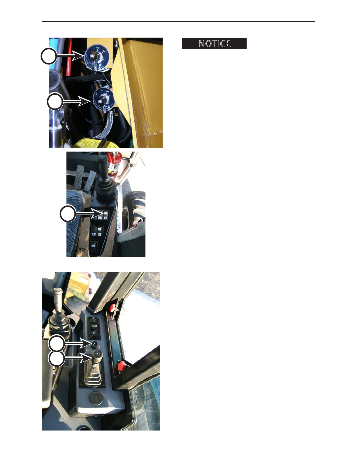
NOTICE
A
OPERATION
STARTING THE ENGINE
Before starting engine, refer
to Pre-Start Inspection Section.
1. Be sure primary & secondary battery disconnect
master switchs (A) are ON (located in LH engine
compartment).
2. Close cab door and fasten seat belt snugly.
A
3. Remove feet from pedals before attempting to
start engine.
4. Set parking brake (B).
B
5. Verify that transmission is in neutral (C).
6. Turn ignition key (D) to RUN position.
D
C
0108 TRANS
2546/2548 T3 1108
73
Page 100
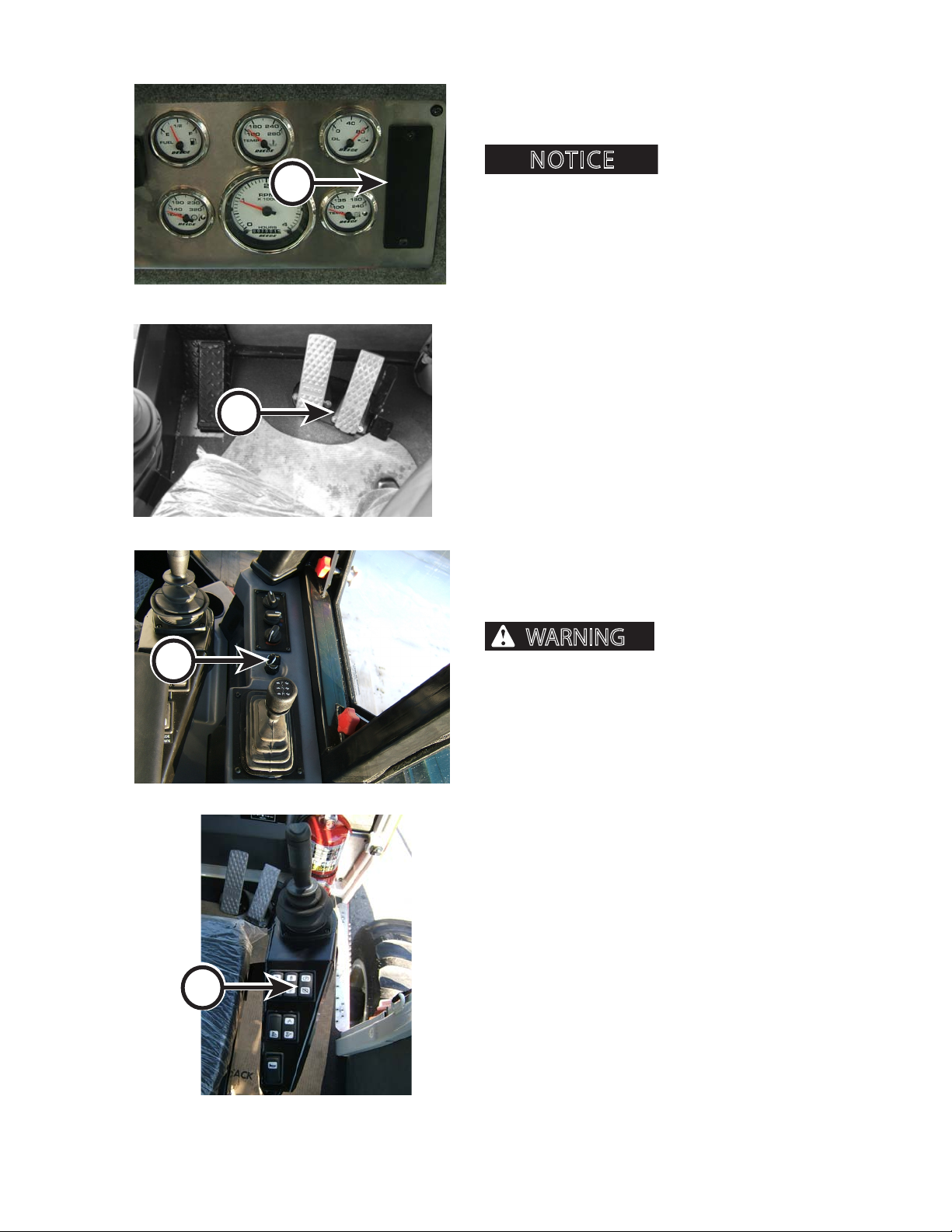
NOTICE
WARNING
A
OPERATION
STARTING THE ENGINE, CONTINUED
7. Verify that all warning indicators (A) are not illuminated. If engine warning indicators are lit, see
COLD WEATHER START procedure in this section.
Never try to start engine by
pushing or towing machine. Attempting to start engine
by towing or pushing machine will result in damage to
your transmission.
8. Depress throttle pedal (D) to one third (1/3) power.
0108 GAUGE PANEL
9. Turn ignition key (E) to START position. Release key
when engine starts. If engine fails to start within
thirty (30) seconds, turn key to OFF position and
wait at least two (2) minutes to allow starting motor to cool.
If engine fails to start after four (4) attempts,
troubleshoot and correct the problem.
D
DO NOT turn key to START while engine is run-
ning. Doing so can cause damage to starter.
10. Run engine at one third (1/3) throttle and no load
for approximately ve (5) minutes to allow engine
146.05
E
to warm up.
11. After allowing engine and hydraulic compo-
nents adequate warm up time, run engine at full
throttle.
12. Before driving machine, release parking brake (F).
If machine can be propelled with parking brake engaged, the system is
not working as intended. Shut engine down and
contact your authorized dealer immediately for
system repair.
2546/2548 T3
0108 TRANS
F
74
1108
 Loading...