

Page 1

The owner friendly®phone system for small business
TalkSwitch User Guide
Release 7.10
Page 2

Copyright Information
Copyright © 2012 Fortinet, Inc. All rights reserved. Fortinet®, FortiGate®, FortiGuard®,
FortiCare®, FortiManager®, FortiAnalyzer®, and TalkSwitch® are registered trademarks of
Fortinet, Inc. and other Fortinet names herein may also be registered trademarks and/or
common law trademarks of Fortinet. Other product or company names may be trademarks of
their respective owners.
Reproduction, adaptation or translation without prior written permission is prohibited, except
as allowed under the copyright laws.
Information in this user guide is subject to change without notice and does not represent any
commitment on the part of TalkSwitch. No part of this user guide may be reproduced or
transmitted in any form or by any means, electronic or mechanical, including photocopying,
recording, or information storage and retrieval systems, or translated to another language, for
any purpose other than the licensee’s personal use and, as specifically allowed in the licensing
agreement, without the express written permission of TalkSwitch.
Release 7.10, January 2012
CT.TS005.003906
Page 3

TABLE OF CONTENTS
CHAPTER 1: INTRODUCTION . . . . . . . . . . . . . . . . . . . . . . . . . . . . . . . . . . . . . . . . . . . . . . . . . . . . . . . . . . . . . . . . . 1
Important information. . . . . . . . . . . . . . . . . . . . . . . . . . . . . . . . . . . . . . . . . . . . . . . . . . . . . . . . . . . . . . . . . 1
What happens if the power goes out or if the IP network to VoIP fails? . . . . . . . . . . . . . . . . . . . . . . 1
Change password frequently . . . . . . . . . . . . . . . . . . . . . . . . . . . . . . . . . . . . . . . . . . . . . . . . . . . . . . . 1
PBX fraud. . . . . . . . . . . . . . . . . . . . . . . . . . . . . . . . . . . . . . . . . . . . . . . . . . . . . . . . . . . . . . . . . . . . . . . 1
Emergency service numbers. . . . . . . . . . . . . . . . . . . . . . . . . . . . . . . . . . . . . . . . . . . . . . . . . . . . . . . . 1
Call redirection and service provider billing advisory. . . . . . . . . . . . . . . . . . . . . . . . . . . . . . . . . . . . 1
CHAPTER 2: CONFIGURATION . . . . . . . . . . . . . . . . . . . . . . . . . . . . . . . . . . . . . . . . . . . . . . . . . . . . . . . . . . . . . . . . 2
Introduction . . . . . . . . . . . . . . . . . . . . . . . . . . . . . . . . . . . . . . . . . . . . . . . . . . . . . . . . . . . . . . . . . . . . . . . . . 2
Starting the Management software . . . . . . . . . . . . . . . . . . . . . . . . . . . . . . . . . . . . . . . . . . . . . . . . . . . . . . 2
About . . . . . . . . . . . . . . . . . . . . . . . . . . . . . . . . . . . . . . . . . . . . . . . . . . . . . . . . . . . . . . . . . . . . . . . . . . . . . . 5
System time . . . . . . . . . . . . . . . . . . . . . . . . . . . . . . . . . . . . . . . . . . . . . . . . . . . . . . . . . . . . . . . . . . . . 5
Current mode . . . . . . . . . . . . . . . . . . . . . . . . . . . . . . . . . . . . . . . . . . . . . . . . . . . . . . . . . . . . . . . . . . . 5
My system . . . . . . . . . . . . . . . . . . . . . . . . . . . . . . . . . . . . . . . . . . . . . . . . . . . . . . . . . . . . . . . . . . . . . . 6
Voicemail messages . . . . . . . . . . . . . . . . . . . . . . . . . . . . . . . . . . . . . . . . . . . . . . . . . . . . . . . . . . . . . . 6
Administration. . . . . . . . . . . . . . . . . . . . . . . . . . . . . . . . . . . . . . . . . . . . . . . . . . . . . . . . . . . . . . . . . . . . . . . 7
Administration . . . . . . . . . . . . . . . . . . . . . . . . . . . . . . . . . . . . . . . . . . . . . . . . . . . . . . . . . . . . . . . . . . 7
System numbering plan . . . . . . . . . . . . . . . . . . . . . . . . . . . . . . . . . . . . . . . . . . . . . . . . . . . . . . . . . . . 8
Region selection . . . . . . . . . . . . . . . . . . . . . . . . . . . . . . . . . . . . . . . . . . . . . . . . . . . . . . . . . . . . . . . . . 8
Language. . . . . . . . . . . . . . . . . . . . . . . . . . . . . . . . . . . . . . . . . . . . . . . . . . . . . . . . . . . . . . . . . . . . . . . 8
Dial 0 or 9 routing. . . . . . . . . . . . . . . . . . . . . . . . . . . . . . . . . . . . . . . . . . . . . . . . . . . . . . . . . . . . . . . . 8
Scheduling . . . . . . . . . . . . . . . . . . . . . . . . . . . . . . . . . . . . . . . . . . . . . . . . . . . . . . . . . . . . . . . . . . . . . . . . . 10
Modes . . . . . . . . . . . . . . . . . . . . . . . . . . . . . . . . . . . . . . . . . . . . . . . . . . . . . . . . . . . . . . . . . . . . . . . . 10
Change mode . . . . . . . . . . . . . . . . . . . . . . . . . . . . . . . . . . . . . . . . . . . . . . . . . . . . . . . . . . . . . . . . . . 12
Remotely. . . . . . . . . . . . . . . . . . . . . . . . . . . . . . . . . . . . . . . . . . . . . . . . . . . . . . . . . . . . . . . . . . 12
Locally. . . . . . . . . . . . . . . . . . . . . . . . . . . . . . . . . . . . . . . . . . . . . . . . . . . . . . . . . . . . . . . . . . . . 12
Scheduling . . . . . . . . . . . . . . . . . . . . . . . . . . . . . . . . . . . . . . . . . . . . . . . . . . . . . . . . . . . . . . . . . . . . 13
System time . . . . . . . . . . . . . . . . . . . . . . . . . . . . . . . . . . . . . . . . . . . . . . . . . . . . . . . . . . . . . . . . . . . 13
Date & time . . . . . . . . . . . . . . . . . . . . . . . . . . . . . . . . . . . . . . . . . . . . . . . . . . . . . . . . . . . . . . . . . . . . 14
Time zone . . . . . . . . . . . . . . . . . . . . . . . . . . . . . . . . . . . . . . . . . . . . . . . . . . . . . . . . . . . . . . . . . . . . . 14
NTP server . . . . . . . . . . . . . . . . . . . . . . . . . . . . . . . . . . . . . . . . . . . . . . . . . . . . . . . . . . . . . . . . . . . . . 14
IP Configuration . . . . . . . . . . . . . . . . . . . . . . . . . . . . . . . . . . . . . . . . . . . . . . . . . . . . . . . . . . . . . . . . . . . . . 15
System IP settings . . . . . . . . . . . . . . . . . . . . . . . . . . . . . . . . . . . . . . . . . . . . . . . . . . . . . . . . . . . . . . 15
Local proxy . . . . . . . . . . . . . . . . . . . . . . . . . . . . . . . . . . . . . . . . . . . . . . . . . . . . . . . . . . . . . . . . . . . . 16
Public IP address . . . . . . . . . . . . . . . . . . . . . . . . . . . . . . . . . . . . . . . . . . . . . . . . . . . . . . . . . . . . . . . 16
Router port forwarding . . . . . . . . . . . . . . . . . . . . . . . . . . . . . . . . . . . . . . . . . . . . . . . . . . . . . . . . . . . 17
Configuring the router manually . . . . . . . . . . . . . . . . . . . . . . . . . . . . . . . . . . . . . . . . . . . . . . . 18
On-Hold/Ringback . . . . . . . . . . . . . . . . . . . . . . . . . . . . . . . . . . . . . . . . . . . . . . . . . . . . . . . . . . . . . . . . . . . 20
On-hold settings . . . . . . . . . . . . . . . . . . . . . . . . . . . . . . . . . . . . . . . . . . . . . . . . . . . . . . . . . . . . . . . . 20
Deleting a music on hold file . . . . . . . . . . . . . . . . . . . . . . . . . . . . . . . . . . . . . . . . . . . . . . . . . . . . . . 21
Playing music on hold on the PA system . . . . . . . . . . . . . . . . . . . . . . . . . . . . . . . . . . . . . . . . . . . . . 21
TABLE OF CONTENTS I
Page 4

Transfer settings. . . . . . . . . . . . . . . . . . . . . . . . . . . . . . . . . . . . . . . . . . . . . . . . . . . . . . . . . . . . . . . . 22
Email Service . . . . . . . . . . . . . . . . . . . . . . . . . . . . . . . . . . . . . . . . . . . . . . . . . . . . . . . . . . . . . . . . . . . . . . . 23
Email notification settings . . . . . . . . . . . . . . . . . . . . . . . . . . . . . . . . . . . . . . . . . . . . . . . . . . . . . . . . 23
Import an email list. . . . . . . . . . . . . . . . . . . . . . . . . . . . . . . . . . . . . . . . . . . . . . . . . . . . . . . . . . . . . . 24
E-mail server settings . . . . . . . . . . . . . . . . . . . . . . . . . . . . . . . . . . . . . . . . . . . . . . . . . . . . . . . . . . . . 24
Outgoing server authentication . . . . . . . . . . . . . . . . . . . . . . . . . . . . . . . . . . . . . . . . . . . . . . . . . . . . 25
Outgoing server port numbers . . . . . . . . . . . . . . . . . . . . . . . . . . . . . . . . . . . . . . . . . . . . . . . . . . . . . 26
Incoming server authentication . . . . . . . . . . . . . . . . . . . . . . . . . . . . . . . . . . . . . . . . . . . . . . . . . . . . 26
Incoming server port numbers. . . . . . . . . . . . . . . . . . . . . . . . . . . . . . . . . . . . . . . . . . . . . . . . . . . . . 27
Incoming mail server options. . . . . . . . . . . . . . . . . . . . . . . . . . . . . . . . . . . . . . . . . . . . . . . . . . . . . . 27
Testing the e-mail server settings . . . . . . . . . . . . . . . . . . . . . . . . . . . . . . . . . . . . . . . . . . . . . . . . . . 28
Managing voicemail messages . . . . . . . . . . . . . . . . . . . . . . . . . . . . . . . . . . . . . . . . . . . . . . . . . . . . 28
Setting up POP3 service with Microsoft Exchange . . . . . . . . . . . . . . . . . . . . . . . . . . . . . . . . . . . . . 29
Risks of enabling POP3 service. . . . . . . . . . . . . . . . . . . . . . . . . . . . . . . . . . . . . . . . . . . . . . . . 29
Security recommendations . . . . . . . . . . . . . . . . . . . . . . . . . . . . . . . . . . . . . . . . . . . . . . . . . . . 29
VoIP Configuration. . . . . . . . . . . . . . . . . . . . . . . . . . . . . . . . . . . . . . . . . . . . . . . . . . . . . . . . . . . . . . . . . . . 30
Setting up a multi-branch profile. . . . . . . . . . . . . . . . . . . . . . . . . . . . . . . . . . . . . . . . . . . . . . . . . . . 30
Activate profile . . . . . . . . . . . . . . . . . . . . . . . . . . . . . . . . . . . . . . . . . . . . . . . . . . . . . . . . . . . . . . . . . 30
Provisioning details . . . . . . . . . . . . . . . . . . . . . . . . . . . . . . . . . . . . . . . . . . . . . . . . . . . . . . . . . . . . . 31
SIP server . . . . . . . . . . . . . . . . . . . . . . . . . . . . . . . . . . . . . . . . . . . . . . . . . . . . . . . . . . . . . . . . . 31
SIP client . . . . . . . . . . . . . . . . . . . . . . . . . . . . . . . . . . . . . . . . . . . . . . . . . . . . . . . . . . . . . . . . . 31
Authentication . . . . . . . . . . . . . . . . . . . . . . . . . . . . . . . . . . . . . . . . . . . . . . . . . . . . . . . . . . . . . . . . . 31
System VoIP options. . . . . . . . . . . . . . . . . . . . . . . . . . . . . . . . . . . . . . . . . . . . . . . . . . . . . . . . . . . . . 31
VoIP Caller ID . . . . . . . . . . . . . . . . . . . . . . . . . . . . . . . . . . . . . . . . . . . . . . . . . . . . . . . . . . . . . . 31
Line reservation . . . . . . . . . . . . . . . . . . . . . . . . . . . . . . . . . . . . . . . . . . . . . . . . . . . . . . . . . . . . 32
Setting up a service provider profile . . . . . . . . . . . . . . . . . . . . . . . . . . . . . . . . . . . . . . . . . . . . . . . . 33
Activate profile . . . . . . . . . . . . . . . . . . . . . . . . . . . . . . . . . . . . . . . . . . . . . . . . . . . . . . . . . . . . . . . . . 33
Automatic configuration . . . . . . . . . . . . . . . . . . . . . . . . . . . . . . . . . . . . . . . . . . . . . . . . . . . . . 33
Manual configuration . . . . . . . . . . . . . . . . . . . . . . . . . . . . . . . . . . . . . . . . . . . . . . . . . . . . . . . 34
Provisioning details . . . . . . . . . . . . . . . . . . . . . . . . . . . . . . . . . . . . . . . . . . . . . . . . . . . . . . . . . . . . . 35
Viewing registrar entries . . . . . . . . . . . . . . . . . . . . . . . . . . . . . . . . . . . . . . . . . . . . . . . . . . . . . . . . . 35
Viewing registration status . . . . . . . . . . . . . . . . . . . . . . . . . . . . . . . . . . . . . . . . . . . . . . . . . . . . . . . 36
Setting codec options. . . . . . . . . . . . . . . . . . . . . . . . . . . . . . . . . . . . . . . . . . . . . . . . . . . . . . . . . . . . 37
Local Extensions/Fax . . . . . . . . . . . . . . . . . . . . . . . . . . . . . . . . . . . . . . . . . . . . . . . . . . . . . . . . . . . . . . . . . 38
Local Extensions/Fax page . . . . . . . . . . . . . . . . . . . . . . . . . . . . . . . . . . . . . . . . . . . . . . . . . . . . . . . . 38
Extension tab . . . . . . . . . . . . . . . . . . . . . . . . . . . . . . . . . . . . . . . . . . . . . . . . . . . . . . . . . . . . . . . . . . 39
Direct line access . . . . . . . . . . . . . . . . . . . . . . . . . . . . . . . . . . . . . . . . . . . . . . . . . . . . . . . . . . . . . . . 41
Hotline access. . . . . . . . . . . . . . . . . . . . . . . . . . . . . . . . . . . . . . . . . . . . . . . . . . . . . . . . . . . . . . . . . . 42
Hunt group permissions. . . . . . . . . . . . . . . . . . . . . . . . . . . . . . . . . . . . . . . . . . . . . . . . . . . . . . . . . . 43
Caller ID settings. . . . . . . . . . . . . . . . . . . . . . . . . . . . . . . . . . . . . . . . . . . . . . . . . . . . . . . . . . . . . . . . 43
Regular extension details. . . . . . . . . . . . . . . . . . . . . . . . . . . . . . . . . . . . . . . . . . . . . . . . . . . . . . . . . 44
IP extension details . . . . . . . . . . . . . . . . . . . . . . . . . . . . . . . . . . . . . . . . . . . . . . . . . . . . . . . . . . . . . 44
Configuring IP phone keys. . . . . . . . . . . . . . . . . . . . . . . . . . . . . . . . . . . . . . . . . . . . . . . . . . . . 45
Setting handset ID for 850i or 860i phones. . . . . . . . . . . . . . . . . . . . . . . . . . . . . . . . . . . . . . 45
Counterpath or other IP phone . . . . . . . . . . . . . . . . . . . . . . . . . . . . . . . . . . . . . . . . . . . . . . . . 45
About call cascades . . . . . . . . . . . . . . . . . . . . . . . . . . . . . . . . . . . . . . . . . . . . . . . . . . . . . . . . . . . . . 45
Setting up call handling . . . . . . . . . . . . . . . . . . . . . . . . . . . . . . . . . . . . . . . . . . . . . . . . . . . . . . . . . . 46
Busy call cascade. . . . . . . . . . . . . . . . . . . . . . . . . . . . . . . . . . . . . . . . . . . . . . . . . . . . . . . . . . . 46
No answer call cascade . . . . . . . . . . . . . . . . . . . . . . . . . . . . . . . . . . . . . . . . . . . . . . . . . . . . .
. 47
Answered call cascade . . . . . . . . . . . . . . . . . . . . . . . . . . . . . . . . . . . . . . . . . . . . . . . . . . . . . . 49
Do not disturb cascade . . . . . . . . . . . . . . . . . . . . . . . . . . . . . . . . . . . . . . . . . . . . . . . . . . . . . . 50
Setting do not disturb mode . . . . . . . . . . . . . . . . . . . . . . . . . . . . . . . . . . . . . . . . . . . . . . . . . . 51
Ignoring call cascades for unanswered intercom calls . . . . . . . . . . . . . . . . . . . . . . . . . . . . . . . . . . 51
Ignoring call cascades for calls transferred from local extensions . . . . . . . . . . . . . . . . . . . . . . . . 51
Voicemail tab . . . . . . . . . . . . . . . . . . . . . . . . . . . . . . . . . . . . . . . . . . . . . . . . . . . . . . . . . . . . . . . . . . 52
TABLE OF CONTENTS II
Page 5

Mailbox greeting. . . . . . . . . . . . . . . . . . . . . . . . . . . . . . . . . . . . . . . . . . . . . . . . . . . . . . . . . . . . . . . . 53
Caller options . . . . . . . . . . . . . . . . . . . . . . . . . . . . . . . . . . . . . . . . . . . . . . . . . . . . . . . . . . . . . . . . . . 54
Notification options . . . . . . . . . . . . . . . . . . . . . . . . . . . . . . . . . . . . . . . . . . . . . . . . . . . . . . . . . . . . . 54
Setting up notification by e-mail . . . . . . . . . . . . . . . . . . . . . . . . . . . . . . . . . . . . . . . . . . . . . . 54
Setting up notification by phone. . . . . . . . . . . . . . . . . . . . . . . . . . . . . . . . . . . . . . . . . . . . . . . 55
Setting up notification by pager . . . . . . . . . . . . . . . . . . . . . . . . . . . . . . . . . . . . . . . . . . . . . . . 56
Setting up the notification options . . . . . . . . . . . . . . . . . . . . . . . . . . . . . . . . . . . . . . . . . . . . . 56
Setting up message waiting light activation . . . . . . . . . . . . . . . . . . . . . . . . . . . . . . . . . . . . . 57
Voicemail screening. . . . . . . . . . . . . . . . . . . . . . . . . . . . . . . . . . . . . . . . . . . . . . . . . . . . . . . . . 58
Adding IP phones. . . . . . . . . . . . . . . . . . . . . . . . . . . . . . . . . . . . . . . . . . . . . . . . . . . . . . . . . . . . . . . . . . . . 59
Overview. . . . . . . . . . . . . . . . . . . . . . . . . . . . . . . . . . . . . . . . . . . . . . . . . . . . . . . . . . . . . . . . . . . . . . . . . . . 59
Adding 350i, 450i and 550i IP phones . . . . . . . . . . . . . . . . . . . . . . . . . . . . . . . . . . . . . . . . . . . . . . . . . . 59
Connecting the IP phone to the network . . . . . . . . . . . . . . . . . . . . . . . . . . . . . . . . . . . . . . . . . . . . . 59
Adding the extension to the system . . . . . . . . . . . . . . . . . . . . . . . . . . . . . . . . . . . . . . . . . . . . . . . . 59
IP extension details area. . . . . . . . . . . . . . . . . . . . . . . . . . . . . . . . . . . . . . . . . . . . . . . . . . . . . 62
About programmable function keys. . . . . . . . . . . . . . . . . . . . . . . . . . . . . . . . . . . . . . . . . . . . . . . . . 62
Programming 350i function keys. . . . . . . . . . . . . . . . . . . . . . . . . . . . . . . . . . . . . . . . . . . . . . . . . . . 62
Saving a key assignment template . . . . . . . . . . . . . . . . . . . . . . . . . . . . . . . . . . . . . . . . . . . . . . . . . 63
Using a key assignment template . . . . . . . . . . . . . . . . . . . . . . . . . . . . . . . . . . . . . . . . . . . . . . . . . . 63
Programming 450i function keys. . . . . . . . . . . . . . . . . . . . . . . . . . . . . . . . . . . . . . . . . . . . . . . . . . . 63
Programming 550i function keys. . . . . . . . . . . . . . . . . . . . . . . . . . . . . . . . . . . . . . . . . . . . . . . . . . . 64
Programming the 350i, 450i or 550i IP phone as an external IP extension . . . . . . . . . . . . . . . . . 65
If registration does not work . . . . . . . . . . . . . . . . . . . . . . . . . . . . . . . . . . . . . . . . . . . . . . . . . . . . . . 66
Adding 850i and 860i IP phones . . . . . . . . . . . . . . . . . . . . . . . . . . . . . . . . . . . . . . . . . . . . . . . . . . . . . . . 67
Installing the base . . . . . . . . . . . . . . . . . . . . . . . . . . . . . . . . . . . . . . . . . . . . . . . . . . . . . . . . . . . . . . 67
Configuring the phone as an IP extension . . . . . . . . . . . . . . . . . . . . . . . . . . . . . . . . . . . . . . . . . . . . 67
Configuring the 850i or 860i for use within the office . . . . . . . . . . . . . . . . . . . . . . . . . . . . . . . . . . 67
IP extension details area . . . . . . . . . . . . . . . . . . . . . . . . . . . . . . . . . . . . . . . . . . . . . . . . . . . . 69
Programming the phone as an external IP extension . . . . . . . . . . . . . . . . . . . . . . . . . . . . . . . . . . . 69
Using the phone with a traditional phone line . . . . . . . . . . . . . . . . . . . . . . . . . . . . . . . . . . . . . . . . 70
Further configuration . . . . . . . . . . . . . . . . . . . . . . . . . . . . . . . . . . . . . . . . . . . . . . . . . . . . . . . . . . . . 70
Checking and updating firmware. . . . . . . . . . . . . . . . . . . . . . . . . . . . . . . . . . . . . . . . . . . . . . . . . . . 70
Phone programmable key functions. . . . . . . . . . . . . . . . . . . . . . . . . . . . . . . . . . . . . . . . . . . . . . . . . . . . . 71
Adding Polycom IP Phones . . . . . . . . . . . . . . . . . . . . . . . . . . . . . . . . . . . . . . . . . . . . . . . . . . . . . . . . . . . . 73
Adding the extension to the system . . . . . . . . . . . . . . . . . . . . . . . . . . . . . . . . . . . . . . . . . . . . . . . . 73
IP extension details area . . . . . . . . . . . . . . . . . . . . . . . . . . . . . . . . . . . . . . . . . . . . . . . . . . . . . . . . . 74
Configuring the system for external IP extensions . . . . . . . . . . . . . . . . . . . . . . . . . . . . . . . . . . . . . 75
Connecting the Polycom phone to the network. . . . . . . . . . . . . . . . . . . . . . . . . . . . . . . . . . . . . . . . 75
Programming the Polycom IP phone . . . . . . . . . . . . . . . . . . . . . . . . . . . . . . . . . . . . . . . . . . . . . . . . 75
Configuring the phone to point to the firmware files . . . . . . . . . . . . . . . . . . . . . . . . . . . . . . . 76
Adding Grandstream IP phones . . . . . . . . . . . . . . . . . . . . . . . . . . . . . . . . . . . . . . . . . . . . . . . . . . . . . . . . 77
Adding the extension to the system . . . . . . . . . . . . . . . . . . . . . . . . . . . . . . . . . . . . . . . . . . . . . . . . 77
IP extension details area . . . . . . . . . . . . . . . . . . . . . . . . . . . . . . . . . . . . . . . . . . . . . . . . . . . . . . . . . 78
Configuring the system for external IP extensions . . . . . . . . . . . . . . . . . . . . . . . . . . . . . . . . . . . . . 79
Connecting the Grandstream phone to the network. . . . . . . . . . . . . . . . . . . . . . . . . . . . . . . . . . . . 79
Programming a Grandstream IP phone . . . . . . . . . . . . . . . . . . . . . . . . . . . . . . . . . . . . . . . . . . . . . . 79
Adding Counterpath IP phones . . . . . . . . . . . . . . . . . . . . . . . . . . . . . . . . . . . . . . . . . . . . . . . . . . . . . . . . . 81
Adding the extension to the system . . . . . . . . . . . . . . . . . . . . . . . . . . . . . . . . . . . . . . . . . . . . . . . . 81
IP extension details area . . . . . . . . . . . . . . . . . . . . . . . . . . . . . . . . . . . . . . . . . . . . . . . . . . .
. . . . . . 82
Configuring the system for external IP extensions . . . . . . . . . . . . . . . . . . . . . . . . . . . . . . . . . . . . . 82
Configuring a new SIP account. . . . . . . . . . . . . . . . . . . . . . . . . . . . . . . . . . . . . . . . . . . . . . . . . . . . . 83
Updating eyeBeam software . . . . . . . . . . . . . . . . . . . . . . . . . . . . . . . . . . . . . . . . . . . . . . . . . . . . . . 84
Adding Other IP Phones. . . . . . . . . . . . . . . . . . . . . . . . . . . . . . . . . . . . . . . . . . . . . . . . . . . . . . . . . . . . . . . 85
External IP extensions . . . . . . . . . . . . . . . . . . . . . . . . . . . . . . . . . . . . . . . . . . . . . . . . . . . . . . . . . . . . . . . . 85
Configuring the router . . . . . . . . . . . . . . . . . . . . . . . . . . . . . . . . . . . . . . . . . . . . . . . . . . . . . . . . . . . 85
Configuring the router manually . . . . . . . . . . . . . . . . . . . . . . . . . . . . . . . . . . . . . . . . . . . . . . . 87
TABLE OF CONTENTS III
Page 6

Remote Extensions . . . . . . . . . . . . . . . . . . . . . . . . . . . . . . . . . . . . . . . . . . . . . . . . . . . . . . . . . . . . . . . . . . 88
Remote Extension tab. . . . . . . . . . . . . . . . . . . . . . . . . . . . . . . . . . . . . . . . . . . . . . . . . . . . . . . . . . . . 89
About call cascades . . . . . . . . . . . . . . . . . . . . . . . . . . . . . . . . . . . . . . . . . . . . . . . . . . . . . . . . . . . . . 91
Setting up call handling . . . . . . . . . . . . . . . . . . . . . . . . . . . . . . . . . . . . . . . . . . . . . . . . . . . . . . . . . . 91
Voicemail tab . . . . . . . . . . . . . . . . . . . . . . . . . . . . . . . . . . . . . . . . . . . . . . . . . . . . . . . . . . . . . . . . . . 91
Mailbox greeting. . . . . . . . . . . . . . . . . . . . . . . . . . . . . . . . . . . . . . . . . . . . . . . . . . . . . . . . . . . . . . . . 92
Caller options . . . . . . . . . . . . . . . . . . . . . . . . . . . . . . . . . . . . . . . . . . . . . . . . . . . . . . . . . . . . . . . . . . 92
Notification settings . . . . . . . . . . . . . . . . . . . . . . . . . . . . . . . . . . . . . . . . . . . . . . . . . . . . . . . . . . . . . 92
Remote extensions and telephone company services . . . . . . . . . . . . . . . . . . . . . . . . . . . . . . . . . . 92
Ring and Page Groups . . . . . . . . . . . . . . . . . . . . . . . . . . . . . . . . . . . . . . . . . . . . . . . . . . . . . . . . . . . . . . . . 93
About call cascades . . . . . . . . . . . . . . . . . . . . . . . . . . . . . . . . . . . . . . . . . . . . . . . . . . . . . . . . . . . . . 94
Setting up call handling . . . . . . . . . . . . . . . . . . . . . . . . . . . . . . . . . . . . . . . . . . . . . . . . . . . . . . . . . . 94
Caller ID options . . . . . . . . . . . . . . . . . . . . . . . . . . . . . . . . . . . . . . . . . . . . . . . . . . . . . . . . . . . . . . . . 94
General Voice Mailboxes. . . . . . . . . . . . . . . . . . . . . . . . . . . . . . . . . . . . . . . . . . . . . . . . . . . . . . . . . . . . . . 95
Mailbox greeting. . . . . . . . . . . . . . . . . . . . . . . . . . . . . . . . . . . . . . . . . . . . . . . . . . . . . . . . . . . . . . . . 96
Caller options . . . . . . . . . . . . . . . . . . . . . . . . . . . . . . . . . . . . . . . . . . . . . . . . . . . . . . . . . . . . . . . . . . 96
Notification options . . . . . . . . . . . . . . . . . . . . . . . . . . . . . . . . . . . . . . . . . . . . . . . . . . . . . . . . . . . . . 96
Voicemail Preferences . . . . . . . . . . . . . . . . . . . . . . . . . . . . . . . . . . . . . . . . . . . . . . . . . . . . . . . . . . . . . . . . 97
Global message waiting indicator . . . . . . . . . . . . . . . . . . . . . . . . . . . . . . . . . . . . . . . . . . . . . . . . . . 97
Mailbox setting . . . . . . . . . . . . . . . . . . . . . . . . . . . . . . . . . . . . . . . . . . . . . . . . . . . . . . . . . . . . . . . . . 97
Mailbox access . . . . . . . . . . . . . . . . . . . . . . . . . . . . . . . . . . . . . . . . . . . . . . . . . . . . . . . . . . . . . . . . . 98
Voicemail management . . . . . . . . . . . . . . . . . . . . . . . . . . . . . . . . . . . . . . . . . . . . . . . . . . . . . . . . . . 98
Mailbox status . . . . . . . . . . . . . . . . . . . . . . . . . . . . . . . . . . . . . . . . . . . . . . . . . . . . . . . . . . . . . . . . . 98
Unassigned messages. . . . . . . . . . . . . . . . . . . . . . . . . . . . . . . . . . . . . . . . . . . . . . . . . . . . . . . 98
Reset mailboxes . . . . . . . . . . . . . . . . . . . . . . . . . . . . . . . . . . . . . . . . . . . . . . . . . . . . . . . . . . . . . . . . 98
Delete password . . . . . . . . . . . . . . . . . . . . . . . . . . . . . . . . . . . . . . . . . . . . . . . . . . . . . . . . . . . . . . . . 99
Voicemail Broadcast . . . . . . . . . . . . . . . . . . . . . . . . . . . . . . . . . . . . . . . . . . . . . . . . . . . . . . . . . . . . . . . . 100
Add Broadcast Group . . . . . . . . . . . . . . . . . . . . . . . . . . . . . . . . . . . . . . . . . . . . . . . . . . . . . . . . . . . 100
Permissions . . . . . . . . . . . . . . . . . . . . . . . . . . . . . . . . . . . . . . . . . . . . . . . . . . . . . . . . . . . . . . . . . . . . . . . 100
Activate access codes. . . . . . . . . . . . . . . . . . . . . . . . . . . . . . . . . . . . . . . . . . . . . . . . . . . . . . . . . . . 101
Access code configuration . . . . . . . . . . . . . . . . . . . . . . . . . . . . . . . . . . . . . . . . . . . . . . . . . . . . . . . 101
Adding an access code . . . . . . . . . . . . . . . . . . . . . . . . . . . . . . . . . . . . . . . . . . . . . . . . . . . . . 101
Removing an access code . . . . . . . . . . . . . . . . . . . . . . . . . . . . . . . . . . . . . . . . . . . . . . . . . . . 102
Extensions requiring an access code. . . . . . . . . . . . . . . . . . . . . . . . . . . . . . . . . . . . . . . . . . . . . . . 102
Restricting extensions . . . . . . . . . . . . . . . . . . . . . . . . . . . . . . . . . . . . . . . . . . . . . . . . . . . . . . 102
Selecting all extensions. . . . . . . . . . . . . . . . . . . . . . . . . . . . . . . . . . . . . . . . . . . . . . . . . . . . . 102
Clearing restrictions . . . . . . . . . . . . . . . . . . . . . . . . . . . . . . . . . . . . . . . . . . . . . . . . . . . . . . . 102
System Speed Dials. . . . . . . . . . . . . . . . . . . . . . . . . . . . . . . . . . . . . . . . . . . . . . . . . . . . . . . . . . . . . . . . . 103
Activate speed dial . . . . . . . . . . . . . . . . . . . . . . . . . . . . . . . . . . . . . . . . . . . . . . . . . . . . . . . . . . . . . 103
Import system speed dial list. . . . . . . . . . . . . . . . . . . . . . . . . . . . . . . . . . . . . . . . . . . . . . . . . . . . . 104
Export system speed dial list . . . . . . . . . . . . . . . . . . . . . . . . . . . . . . . . . . . . . . . . . . . . . . . . . . . . . 105
Caller ID name tagging . . . . . . . . . . . . . . . . . . . . . . . . . . . . . . . . . . . . . . . . . . . . . . . . . . . . . . . . . . 106
Telephone Lines. . . . . . . . . . . . . . . . . . . . . . . . . . . . . . . . . . . . . . . . . . . . . . . . . . . . . . . . . . . . . . . . . . . . 107
Activate line . . . . . . . . . . . . . . . . . . . . . . . . . . . . . . . . . . . . . . . . . . . . . . . . . . . . . . . . . . . . . . . . . . 107
Phone numbers. . . . . . . . . . . . . . . . . . . . . . . . . . . . . . . . . . . . . . . . . . . . . . . . . . . . . . . . . . . . . . . . 107
Phone line services. . . . . . . . . . . . . . . . . . . . . . . . . . . . . . . . . . . . . . . . . . . . . . . . . . . . . . . . . . . . . 108
Line reversal settings . . . . . . . . . . . . . . . . . . . . . . . . . . . . . . . . . . . . . . . . . . . . . . . . . . . . . . . . . . . 109
Call handling. . . . . . . . . . . . . . . . . . . . . . . . . . . . . . . . . . . . . . . . . . . . . . . . . . . . . . . . . . . . . . . . . . 109
Line optimization . . . . . . . . . . . . . . . . . . . . . . . . . . . . . . . . . . . . . . . . . . . . . . . . . . . . . . . . . . . . . . 111
VoIP Numbers . . . . . . . . . . . . . . . . . . . . . . . . . . . . . . . . . . . . . . . . . . . . . . . . . . . . . . . . . . . . . . . . . . . . . 112
Activate VoIP number . . . . . . . . . . . . . . . . . . . . . . . . . . . . . . . . . . . . . . . . . . . . . . . . . . . . . . . . . . . 112
Phone number. . . . . . . . . . . . . . . . . . . . . . . . . . . . . . . . . . . . . . . . . . . . . . . . . . . . . . . . . . . . . . . . . 113
Multi-branch profile. . . . . . . . . . . . . . . . . . . . . . . . . . . . . . . . . . . . . . . . . . . . . . . . . . . . . . . . 113
Service provider profile . . . . . . . . . . . . . . . . . . . . . . . . . . . . . . . . . . . . . . . . . . . . . . . . . . . . . 113
Username and password . . . . . . . . . . . . . . . . . . . . . . . . . . . . . . . . . . . . . . . . . . . . . . . . . . . . . . . . 113
Registration status . . . . . . . . . . . . . . . . . . . . . . . . . . . . . . . . . . . . . . . . . . . . . . . . . . . . . . . . . . . . . 114
TABLE OF CONTENTS IV
Page 7

Call handling. . . . . . . . . . . . . . . . . . . . . . . . . . . . . . . . . . . . . . . . . . . . . . . . . . . . . . . . . . . . . . . . . . 114
Caller ID (or CLID) Based Routing . . . . . . . . . . . . . . . . . . . . . . . . . . . . . . . . . . . . . . . . . . . . . . . . . . . . . . 116
Caller ID lookup list or CLID matching list . . . . . . . . . . . . . . . . . . . . . . . . . . . . . . . . . . . . . . . . . . . 117
Caller ID or CLID Routing Groups . . . . . . . . . . . . . . . . . . . . . . . . . . . . . . . . . . . . . . . . . . . . . . . . . . 117
Setting up caller ID routing with an extension . . . . . . . . . . . . . . . . . . . . . . . . . . . . . . . . . . . . . . . 119
Line Hunt Groups. . . . . . . . . . . . . . . . . . . . . . . . . . . . . . . . . . . . . . . . . . . . . . . . . . . . . . . . . . . . . . . . . . . 120
Activate hunt group . . . . . . . . . . . . . . . . . . . . . . . . . . . . . . . . . . . . . . . . . . . . . . . . . . . . . . . . . . . . 121
Hunt group line assignments . . . . . . . . . . . . . . . . . . . . . . . . . . . . . . . . . . . . . . . . . . . . . . . . . . . . . 121
Hunting order for outgoing calls . . . . . . . . . . . . . . . . . . . . . . . . . . . . . . . . . . . . . . . . . . . . . . . . . . 122
Hunt group busy overflow for outgoing calls . . . . . . . . . . . . . . . . . . . . . . . . . . . . . . . . . . . . . . . . . 122
Overflow tone notification . . . . . . . . . . . . . . . . . . . . . . . . . . . . . . . . . . . . . . . . . . . . . . . . . . . . . . . 123
Auto AttendanTS . . . . . . . . . . . . . . . . . . . . . . . . . . . . . . . . . . . . . . . . . . . . . . . . . . . . . . . . . . . . . . . . . . . 124
Configuring auto attendants . . . . . . . . . . . . . . . . . . . . . . . . . . . . . . . . . . . . . . . . . . . . . . . . . . . . . 125
Actions during auto attendant playback . . . . . . . . . . . . . . . . . . . . . . . . . . . . . . . . . . . . . . . . . . . . 126
Action performed after auto attendant playback . . . . . . . . . . . . . . . . . . . . . . . . . . . . . . . . . . . . . 127
Working with auto attendant messages . . . . . . . . . . . . . . . . . . . . . . . . . . . . . . . . . . . . . . . . . . . . 127
Recording a new message. . . . . . . . . . . . . . . . . . . . . . . . . . . . . . . . . . . . . . . . . . . . . . . . . . . 127
Listening to the recorded message. . . . . . . . . . . . . . . . . . . . . . . . . . . . . . . . . . . . . . . . . . . . 128
Loading a message . . . . . . . . . . . . . . . . . . . . . . . . . . . . . . . . . . . . . . . . . . . . . . . . . . . . . . . . 128
Erasing a message . . . . . . . . . . . . . . . . . . . . . . . . . . . . . . . . . . . . . . . . . . . . . . . . . . . . . . . . . 128
Example auto attendant . . . . . . . . . . . . . . . . . . . . . . . . . . . . . . . . . . . . . . . . . . . . . . . . . . . . . . . . . 129
Setting up the dial-by-name directory. . . . . . . . . . . . . . . . . . . . . . . . . . . . . . . . . . . . . . . . . . . . . . 129
Setting the PBX extension length. . . . . . . . . . . . . . . . . . . . . . . . . . . . . . . . . . . . . . . . . . . . . . . . . . 130
Auto Route Selection . . . . . . . . . . . . . . . . . . . . . . . . . . . . . . . . . . . . . . . . . . . . . . . . . . . . . . . . . . . . . . . . 131
Introduction . . . . . . . . . . . . . . . . . . . . . . . . . . . . . . . . . . . . . . . . . . . . . . . . . . . . . . . . . . . . . . . . . . 131
About automatic route selection. . . . . . . . . . . . . . . . . . . . . . . . . . . . . . . . . . . . . . . . . . . . . . 131
About toll restriction . . . . . . . . . . . . . . . . . . . . . . . . . . . . . . . . . . . . . . . . . . . . . . . . . . . . . . . 131
About leading digits. . . . . . . . . . . . . . . . . . . . . . . . . . . . . . . . . . . . . . . . . . . . . . . . . . . . . . . . 131
About carrier codes . . . . . . . . . . . . . . . . . . . . . . . . . . . . . . . . . . . . . . . . . . . . . . . . . . . . . . . . 132
ARS and direct line access . . . . . . . . . . . . . . . . . . . . . . . . . . . . . . . . . . . . . . . . . . . . . . . . . . 132
ARS and the 3-Way Calling/Conference service . . . . . . . . . . . . . . . . . . . . . . . . . . . . . . . . . . 132
ARS and emergency service numbers. . . . . . . . . . . . . . . . . . . . . . . . . . . . . . . . . . . . . . . . . . 132
Planning automatic route selection and toll restriction . . . . . . . . . . . . . . . . . . . . . . . . . . . . . . . . 132
Setting up automatic route selection and toll restriction . . . . . . . . . . . . . . . . . . . . . . . . . . . . . . . 133
Activate automatic route selection . . . . . . . . . . . . . . . . . . . . . . . . . . . . . . . . . . . . . . . . . . . . . . . . 133
Carrier code prefixes. . . . . . . . . . . . . . . . . . . . . . . . . . . . . . . . . . . . . . . . . . . . . . . . . . . . . . . . . . . . 134
Emergency service numbers. . . . . . . . . . . . . . . . . . . . . . . . . . . . . . . . . . . . . . . . . . . . . . . . . . . . . . 134
Auto route selection . . . . . . . . . . . . . . . . . . . . . . . . . . . . . . . . . . . . . . . . . . . . . . . . . . . . . . . . . . . . 134
Restricting local extension access to specific hunt groups . . . . . . . . . . . . . . . . . . . . . . . . . . . . . 135
Allowing a local extension to bypass ARS and toll restriction . . . . . . . . . . . . . . . . . . . . . . . . . . . 135
Regulatory advisory notice . . . . . . . . . . . . . . . . . . . . . . . . . . . . . . . . . . . . . . . . . . . . . . . . . . . . . . 136
Call Bridge (DISA). . . . . . . . . . . . . . . . . . . . . . . . . . . . . . . . . . . . . . . . . . . . . . . . . . . . . . . . . . . . . . . . . . . 137
Using call bridge . . . . . . . . . . . . . . . . . . . . . . . . . . . . . . . . . . . . . . . . . . . . . . . . . . . . . . . . . . . . . . . 137
Activate account . . . . . . . . . . . . . . . . . . . . . . . . . . . . . . . . . . . . . . . . . . . . . . . . . . . . . . . . . . . . . . . 137
Hunt group access . . . . . . . . . . . . . . . . . . . . . . . . . . . . . . . . . . . . . . . . . . . . . . . . . . . . . . . . . . . . . 138
Auto Call Back . . . . . . . . . . . . . . . . . . . . . . . . . . . . . . . . . . . . . . . . . . . . . . . . . . . . . . . . . . . . . . . . . . . . . 139
Using auto call back . . . . . . . . . . . . . . . . . . . . . . . . . . . . . . . . . . . . . . . . . . . . . . . . . . . . . . . . . . . . 139
Activate auto call back . . . . . . . . . . . . . . . . . . . . . . . . . . . . . . . . . . . . . . . . . . . . . . . . . . . . . . . . . . 140
Account options . . . . . . . . . . . . . . . . . . . . . . . . . . . . . . . . . . . . . . . . . . . . . . . . . . . . . . . .
. . . . . . . 141
Recording an announced message . . . . . . . . . . . . . . . . . . . . . . . . . . . . . . . . . . . . . . . . . . . . . . . . 142
Prompted Call Back . . . . . . . . . . . . . . . . . . . . . . . . . . . . . . . . . . . . . . . . . . . . . . . . . . . . . . . . . . . . . . . . . 143
Using prompted call back. . . . . . . . . . . . . . . . . . . . . . . . . . . . . . . . . . . . . . . . . . . . . . . . . . . . . . . . 143
Activate prompted call back. . . . . . . . . . . . . . . . . . . . . . . . . . . . . . . . . . . . . . . . . . . . . . . . . . . . . . 144
Account options . . . . . . . . . . . . . . . . . . . . . . . . . . . . . . . . . . . . . . . . . . . . . . . . . . . . . . . . . . . . . . . 144
Recording an announced message . . . . . . . . . . . . . . . . . . . . . . . . . . . . . . . . . . . . . . . . . . . . . . . . 145
File menu . . . . . . . . . . . . . . . . . . . . . . . . . . . . . . . . . . . . . . . . . . . . . . . . . . . . . . . . . . . . . . . . . . . . . . . . . 146
TABLE OF CONTENTS V
Page 8

New Template . . . . . . . . . . . . . . . . . . . . . . . . . . . . . . . . . . . . . . . . . . . . . . . . . . . . . . . . . . . . . . . . . 146
Open > Location. . . . . . . . . . . . . . . . . . . . . . . . . . . . . . . . . . . . . . . . . . . . . . . . . . . . . . . . . . . . . . . . 147
Open > Configuration File . . . . . . . . . . . . . . . . . . . . . . . . . . . . . . . . . . . . . . . . . . . . . . . . . . . . . . . . 147
Save. . . . . . . . . . . . . . . . . . . . . . . . . . . . . . . . . . . . . . . . . . . . . . . . . . . . . . . . . . . . . . . . . . . . . . . . . 148
Save To > File. . . . . . . . . . . . . . . . . . . . . . . . . . . . . . . . . . . . . . . . . . . . . . . . . . . . . . . . . . . . . . . . . . 148
Save To > Location. . . . . . . . . . . . . . . . . . . . . . . . . . . . . . . . . . . . . . . . . . . . . . . . . . . . . . . . . . . . . . 148
Retrieve Settings. . . . . . . . . . . . . . . . . . . . . . . . . . . . . . . . . . . . . . . . . . . . . . . . . . . . . . . . . . . . . . . 149
Close . . . . . . . . . . . . . . . . . . . . . . . . . . . . . . . . . . . . . . . . . . . . . . . . . . . . . . . . . . . . . . . . . . . . . . . . 149
Exit. . . . . . . . . . . . . . . . . . . . . . . . . . . . . . . . . . . . . . . . . . . . . . . . . . . . . . . . . . . . . . . . . . . . . . . . . . 149
Tools menu. . . . . . . . . . . . . . . . . . . . . . . . . . . . . . . . . . . . . . . . . . . . . . . . . . . . . . . . . . . . . . . . . . . . . . . . 150
Memory Usage . . . . . . . . . . . . . . . . . . . . . . . . . . . . . . . . . . . . . . . . . . . . . . . . . . . . . . . . . . . . . . . . 150
Voicemail Manager > Mailbox Status . . . . . . . . . . . . . . . . . . . . . . . . . . . . . . . . . . . . . . . . . . . . . . . 150
Voicemail Manager > Delete Mailbox Password . . . . . . . . . . . . . . . . . . . . . . . . . . . . . . . . . . . . . . 150
Voicemail Manager > Reset Mailboxes. . . . . . . . . . . . . . . . . . . . . . . . . . . . . . . . . . . . . . . . . . . . . . 150
Terminal Window (CLI) . . . . . . . . . . . . . . . . . . . . . . . . . . . . . . . . . . . . . . . . . . . . . . . . . . . . . . . . . . 150
Syslog Output . . . . . . . . . . . . . . . . . . . . . . . . . . . . . . . . . . . . . . . . . . . . . . . . . . . . . . . . . . . . . . . . . 151
Call Logging Output (CDR) . . . . . . . . . . . . . . . . . . . . . . . . . . . . . . . . . . . . . . . . . . . . . . . . . . . . . . . 151
Defaults > Entire Configuration. . . . . . . . . . . . . . . . . . . . . . . . . . . . . . . . . . . . . . . . . . . . . . . . . . . . 151
Defaults > Current Page . . . . . . . . . . . . . . . . . . . . . . . . . . . . . . . . . . . . . . . . . . . . . . . . . . . . . . . . . 151
Uninstall License . . . . . . . . . . . . . . . . . . . . . . . . . . . . . . . . . . . . . . . . . . . . . . . . . . . . . . . . . . . . . . 151
Click-to-Dial. . . . . . . . . . . . . . . . . . . . . . . . . . . . . . . . . . . . . . . . . . . . . . . . . . . . . . . . . . . . . . . . . . . 151
Update Phone . . . . . . . . . . . . . . . . . . . . . . . . . . . . . . . . . . . . . . . . . . . . . . . . . . . . . . . . . . . . . . . . . 151
Update Firmware. . . . . . . . . . . . . . . . . . . . . . . . . . . . . . . . . . . . . . . . . . . . . . . . . . . . . . . . . . . . . . . 152
Reboot System . . . . . . . . . . . . . . . . . . . . . . . . . . . . . . . . . . . . . . . . . . . . . . . . . . . . . . . . . . . . . . . . 153
Options menu . . . . . . . . . . . . . . . . . . . . . . . . . . . . . . . . . . . . . . . . . . . . . . . . . . . . . . . . . . . . . . . . . . . . . 154
Paging Options . . . . . . . . . . . . . . . . . . . . . . . . . . . . . . . . . . . . . . . . . . . . . . . . . . . . . . . . . . . . . . . . 154
Overhead Paging . . . . . . . . . . . . . . . . . . . . . . . . . . . . . . . . . . . . . . . . . . . . . . . . . . . . . . . . . . 154
Transfer Preferences. . . . . . . . . . . . . . . . . . . . . . . . . . . . . . . . . . . . . . . . . . . . . . . . . . . . . . . . . . . . 154
To local extension tab. . . . . . . . . . . . . . . . . . . . . . . . . . . . . . . . . . . . . . . . . . . . . . . . . . . . . . . . . . . 154
To remote extension tab. . . . . . . . . . . . . . . . . . . . . . . . . . . . . . . . . . . . . . . . . . . . . . . . . . . . . . . . . 155
To ring group tab. . . . . . . . . . . . . . . . . . . . . . . . . . . . . . . . . . . . . . . . . . . . . . . . . . . . . . . . . . . . . . . 156
From auto attendant tab. . . . . . . . . . . . . . . . . . . . . . . . . . . . . . . . . . . . . . . . . . . . . . . . . . . . . . . . . 157
Call Reminders . . . . . . . . . . . . . . . . . . . . . . . . . . . . . . . . . . . . . . . . . . . . . . . . . . . . . . . . . . . . . . . . 157
VoIP Trunking . . . . . . . . . . . . . . . . . . . . . . . . . . . . . . . . . . . . . . . . . . . . . . . . . . . . . . . . . . . . . . . . . 158
SIP server registration
. . . . . . . . . . . . . . . . . . . . . . . . . . . . . . . . . . . . . . . . . . . . . . . . . . . . . . . . . . 158
VoIP ports . . . . . . . . . . . . . . . . . . . . . . . . . . . . . . . . . . . . . . . . . . . . . . . . . . . . . . . . . . . . . . . . . . . . 158
Clock Preferences . . . . . . . . . . . . . . . . . . . . . . . . . . . . . . . . . . . . . . . . . . . . . . . . . . . . . . . . . . . . . . 159
Internal Calls. . . . . . . . . . . . . . . . . . . . . . . . . . . . . . . . . . . . . . . . . . . . . . . . . . . . . . . . . . . . . . . . . . 159
Call Back . . . . . . . . . . . . . . . . . . . . . . . . . . . . . . . . . . . . . . . . . . . . . . . . . . . . . . . . . . . . . . . . . . . . . 160
Caller ID. . . . . . . . . . . . . . . . . . . . . . . . . . . . . . . . . . . . . . . . . . . . . . . . . . . . . . . . . . . . . . . . . . . . . . 160
Dial-by-name Directory. . . . . . . . . . . . . . . . . . . . . . . . . . . . . . . . . . . . . . . . . . . . . . . . . . . . . . . . . . 160
Call Park . . . . . . . . . . . . . . . . . . . . . . . . . . . . . . . . . . . . . . . . . . . . . . . . . . . . . . . . . . . . . . . . . . . . . 160
Set Date & Time . . . . . . . . . . . . . . . . . . . . . . . . . . . . . . . . . . . . . . . . . . . . . . . . . . . . . . . . . . . . . . . 161
Troubleshooting menu . . . . . . . . . . . . . . . . . . . . . . . . . . . . . . . . . . . . . . . . . . . . . . . . . . . . . . . . . . . . . . 162
Auto Attendants . . . . . . . . . . . . . . . . . . . . . . . . . . . . . . . . . . . . . . . . . . . . . . . . . . . . . . . . . . . . . . . 162
Extensions > Regular Analog Extensions . . . . . . . . . . . . . . . . . . . . . . . . . . . . . . . . . . . . . . . . . . . . 163
Extensions > IP Extensions . . . . . . . . . . . . . . . . . . . . . . . . . . . . . . . . . . . . . . . . . . . . . . . . . . . . . . . 164
Fax Detection. . . . . . . . . . . . . . . . . . . . . . . . . . . . . . . . . . . . . . . . . . . . . . . . . . . . . . . . . . . . . . . . . . 165
Telephone Lines > Audio. . . . . . . . . . . . . . . . . . . . . . . . . . . . . . . . . . . . . . . . . . . . . . . . . . . . . . . . . 166
Telephone Lines > Detection and Timers . . . . . . . . . . . . . . . . . . . . . . . . . . . . . . . . . . . . . . . . . . . . 167
VoIP . . . . . . . . . . . . . . . . . . . . . . . . . . . . . . . . . . . . . . . . . . . . . . . . . . . . . . . . . . . . . . . . . . . . . . . . . 168
VoIP ports. . . . . . . . . . . . . . . . . . . . . . . . . . . . . . . . . . . . . . . . . . . . . . . . . . . . . . . . . . . . . . . . 168
SIP Server Registration Timer . . . . . . . . . . . . . . . . . . . . . . . . . . . . . . . . . . . . . . . . . . . . . . . . 168
UPnP . . . . . . . . . . . . . . . . . . . . . . . . . . . . . . . . . . . . . . . . . . . . . . . . . . . . . . . . . . . . . . . . . . . . 168
View Blocked IP Addresses . . . . . . . . . . . . . . . . . . . . . . . . . . . . . . . . . . . . . . . . . . . . . . . . . . 169
Firewall Test . . . . . . . . . . . . . . . . . . . . . . . . . . . . . . . . . . . . . . . . . . . . . . . . . . . . . . . . . . . . . . . . . . 169
TABLE OF CONTENTS VI
Page 9

System Information and Diagnostics . . . . . . . . . . . . . . . . . . . . . . . . . . . . . . . . . . . . . . . . . . . . . . . 170
System Information . . . . . . . . . . . . . . . . . . . . . . . . . . . . . . . . . . . . . . . . . . . . . . . . . . . . . . . . 170
Local Extensions . . . . . . . . . . . . . . . . . . . . . . . . . . . . . . . . . . . . . . . . . . . . . . . . . . . . . . . . . . 170
VoIP Numbers . . . . . . . . . . . . . . . . . . . . . . . . . . . . . . . . . . . . . . . . . . . . . . . . . . . . . . . . . . . . 170
Network . . . . . . . . . . . . . . . . . . . . . . . . . . . . . . . . . . . . . . . . . . . . . . . . . . . . . . . . . . . . . . . . . 170
Memory Usage . . . . . . . . . . . . . . . . . . . . . . . . . . . . . . . . . . . . . . . . . . . . . . . . . . . . . . . . . . . . 170
Support Tools > Call Logging Options . . . . . . . . . . . . . . . . . . . . . . . . . . . . . . . . . . . . . . . . . . . . . . 171
Support Tools > Email Software Configuration Logs . . . . . . . . . . . . . . . . . . . . . . . . . . . . . . . . . . . 172
CHAPTER 3: USING YOUR PHONE SYSTEM . . . . . . . . . . . . . . . . . . . . . . . . . . . . . . . . . . . . . . . . . . . . . . . . . . . . 174
Receiving calls . . . . . . . . . . . . . . . . . . . . . . . . . . . . . . . . . . . . . . . . . . . . . . . . . . . . . . . . . . . . . . . . . . . . . 174
With the auto attendant . . . . . . . . . . . . . . . . . . . . . . . . . . . . . . . . . . . . . . . . . . . . . . . . . . . . . . . . . 174
Using an analog extension . . . . . . . . . . . . . . . . . . . . . . . . . . . . . . . . . . . . . . . . . . . . . . . . . . . . . . . . . . . 175
Making calls . . . . . . . . . . . . . . . . . . . . . . . . . . . . . . . . . . . . . . . . . . . . . . . . . . . . . . . . . . . . . . . . . . 175
Placing an intercom call . . . . . . . . . . . . . . . . . . . . . . . . . . . . . . . . . . . . . . . . . . . . . . . . . . . . 175
Overhead paging . . . . . . . . . . . . . . . . . . . . . . . . . . . . . . . . . . . . . . . . . . . . . . . . . . . . . . . . . . 175
Two-way paging . . . . . . . . . . . . . . . . . . . . . . . . . . . . . . . . . . . . . . . . . . . . . . . . . . . . . . . . . . . 175
One-way group paging. . . . . . . . . . . . . . . . . . . . . . . . . . . . . . . . . . . . . . . . . . . . . . . . . . . . . . 175
Place out-of-office calls from a local extension . . . . . . . . . . . . . . . . . . . . . . . . . . . . . . . . . . 175
Click-to-Dial from Microsoft Outlook. . . . . . . . . . . . . . . . . . . . . . . . . . . . . . . . . . . . . . . . . . . 176
Receiving calls . . . . . . . . . . . . . . . . . . . . . . . . . . . . . . . . . . . . . . . . . . . . . . . . . . . . . . . . . . . . . . . . 176
For your local extension. . . . . . . . . . . . . . . . . . . . . . . . . . . . . . . . . . . . . . . . . . . . . . . . . . . . . 176
For any other local extension . . . . . . . . . . . . . . . . . . . . . . . . . . . . . . . . . . . . . . . . . . . . . . . . 176
For a specific local extension . . . . . . . . . . . . . . . . . . . . . . . . . . . . . . . . . . . . . . . . . . . . . . . . 176
While you’re on a call. . . . . . . . . . . . . . . . . . . . . . . . . . . . . . . . . . . . . . . . . . . . . . . . . . . . . . . 176
Placing calls on hold. . . . . . . . . . . . . . . . . . . . . . . . . . . . . . . . . . . . . . . . . . . . . . . . . . . . . . . . . . . . 177
Transferring calls to an extension . . . . . . . . . . . . . . . . . . . . . . . . . . . . . . . . . . . . . . . . . . . . . . . . . 177
Unscreened transfer . . . . . . . . . . . . . . . . . . . . . . . . . . . . . . . . . . . . . . . . . . . . . . . . . . . . . . . 177
Screened transfer . . . . . . . . . . . . . . . . . . . . . . . . . . . . . . . . . . . . . . . . . . . . . . . . . . . . . . . . . 177
Transferring calls to an outside number . . . . . . . . . . . . . . . . . . . . . . . . . . . . . . . . . . . . . . . . . . . . 177
Unscreened transfer . . . . . . . . . . . . . . . . . . . . . . . . . . . . . . . . . . . . . . . . . . . . . . . . . . . . . . . 178
Screened transfer . . . . . . . . . . . . . . . . . . . . . . . . . . . . . . . . . . . . . . . . . . . . . . . . . . . . . . . . . 178
Parking and retrieving calls . . . . . . . . . . . . . . . . . . . . . . . . . . . . . . . . . . . . . . . . . . . . . . . . . . . . . . 178
Parking a call . . . . . . . . . . . . . . . . . . . . . . . . . . . . . . . . . . . . . . . . . . . . . . . . . . . . . . . . . . . . . 178
Retrieving a parked call. . . . . . . . . . . . . . . . . . . . . . . . . . . . . . . . . . . . . . . . . . . . . . . . . . . . . 178
Queuing and retrieving callers . . . . . . . . . . . . . . . . . . . . . . . . . . . . . . . . . . . . . . . . . . . . . . . . . . . 178
Queuing callers at a local extension . . . . . . . . . . . . . . . . . . . . . . . . . . . . . . . . . . . . . . . . . . . 178
Queuing callers at a ring group . . . . . . . . . . . . . . . . . . . . . . . . . . . . . . . . . . . . . . . . . . . . . . . 179
Using call waiting . . . . . . . . . . . . . . . . . . . . . . . . . . . . . . . . . . . . . . . . . . . . . . . . . . . . . . . . . . . . . . 179
Conference calling . . . . . . . . . . . . . . . . . . . . . . . . . . . . . . . . . . . . . . . . . . . . . . . . . . . . . . . . . . . . . 179
Two local extensions and one outside caller . . . . . . . . . . . . . . . . . . . . . . . . . . . . . . . . . . . . 180
Two outside callers and one local extension . . . . . . . . . . . . . . . . . . . . . . . . . . . . . . . . . . . . 180
Using an IP extension . . . . . . . . . . . . . . . . . . . . . . . . . . . . . . . . . . . . . . . . . . . . . . . . . . . . . . . . . . . . . . . 181
Making calls . . . . . . . . . . . . . . . . . . . . . . . . . . . . . . . . . . . . . . . . . . . . . . . . . . . . . . . . . . . . . . . . . . 181
Placing an intercom call . . . . . . . . . . . . . . . . . . . . . . . . . . . . . . . . . . . . . . . . . . . . . . . . . . . . 181
Overhead paging . . . . . . . . . . . . . . . . . . . . . . . . . . . . . . . . . . . . . . . . . . . . . . . . . . . . . . . . . . 181
Two-way paging . . . . . . . . . . . . . . . . . . . . . . . . . . . . . . . . . . . . . . . . . . . . . . . . . . . . . . . . . . . 181
One-way group paging. . . . . . . . . . . . . . . . . . . . . . . . . . . . . . . . . . . . . . . . . . . . . . . . . . . . . . 181
Place out-of-office calls from a local extension . . . . . . . . . . . . . . . . . . . . . . . . . . . . . . . . . . 181
Receiving calls . . . . . . . . . . . . . . . . . . . . . . . . . . . . . . . . . . . . . . . . . . . . . . . . . . . . . . . . . . . . . . . . 182
For your local extension. . . . . . . . . . . . . . . . . . . . . . . . . . . . . . . . . . . . . . . . . . . . . . . . . . . . . 182
For any other local extension . . . . . . . . . . . . . . . . . . . . . . . . . . . . . . . . . . . . . . . . . . . . . . . . 182
For a specific local extension . . . . . . . . . . . . . . . . . . . . . . . . . . . . . . . . . . . . . . . . . . . . . . . . 182
While you’re on a call. . . . . . . . . . . . . . . . . . . . . . . . . . . . . . . . . . . . . . . . . . . . . . . . . . . . . . . 182
Placing calls on hold. . . . . . . . . . . . . . . . . . . . . . . . . . . . . . . . . . . . . . . . . . . . . . . . . . . . . . . . . . . . 183
TABLE OF CONTENTS VII
Page 10

Transferring calls to an extension . . . . . . . . . . . . . . . . . . . . . . . . . . . . . . . . . . . . . . . . . . . . . . . . . 183
Unscreened transfer . . . . . . . . . . . . . . . . . . . . . . . . . . . . . . . . . . . . . . . . . . . . . . . . . . . . . . . 183
Screened transfer . . . . . . . . . . . . . . . . . . . . . . . . . . . . . . . . . . . . . . . . . . . . . . . . . . . . . . . . . 183
Transferring calls to an outside number . . . . . . . . . . . . . . . . . . . . . . . . . . . . . . . . . . . . . . . . . . . . 183
Unscreened transfer . . . . . . . . . . . . . . . . . . . . . . . . . . . . . . . . . . . . . . . . . . . . . . . . . . . . . . . 184
Screened transfer . . . . . . . . . . . . . . . . . . . . . . . . . . . . . . . . . . . . . . . . . . . . . . . . . . . . . . . . . 184
Call park — parking and retrieving callers . . . . . . . . . . . . . . . . . . . . . . . . . . . . . . . . . . . . . . . . . . 184
Parking a caller . . . . . . . . . . . . . . . . . . . . . . . . . . . . . . . . . . . . . . . . . . . . . . . . . . . . . . . . . . . 184
Retrieving a parked call. . . . . . . . . . . . . . . . . . . . . . . . . . . . . . . . . . . . . . . . . . . . . . . . . . . . . 184
Queuing and retrieving callers . . . . . . . . . . . . . . . . . . . . . . . . . . . . . . . . . . . . . . . . . . . . . . . . . . . . 184
Using call waiting . . . . . . . . . . . . . . . . . . . . . . . . . . . . . . . . . . . . . . . . . . . . . . . . . . . . . . . . . . . . . . 184
Conference calling . . . . . . . . . . . . . . . . . . . . . . . . . . . . . . . . . . . . . . . . . . . . . . . . . . . . . . . . . . . . . 185
Two local extensions and one outside caller . . . . . . . . . . . . . . . . . . . . . . . . . . . . . . . . . . . . 185
Two outside callers and one local extension . . . . . . . . . . . . . . . . . . . . . . . . . . . . . . . . . . . . 185
Programmable phone key functions. . . . . . . . . . . . . . . . . . . . . . . . . . . . . . . . . . . . . . . . . . . . . . . . . . . . 186
Using VoIP . . . . . . . . . . . . . . . . . . . . . . . . . . . . . . . . . . . . . . . . . . . . . . . . . . . . . . . . . . . . . . . . . . . . . . . . 188
Forwarding calls out of the office . . . . . . . . . . . . . . . . . . . . . . . . . . . . . . . . . . . . . . . . . . . . . . . . . . . . . . 189
Automatic call forwarding . . . . . . . . . . . . . . . . . . . . . . . . . . . . . . . . . . . . . . . . . . . . . . . . . . . . . . . 189
Manual call forwarding. . . . . . . . . . . . . . . . . . . . . . . . . . . . . . . . . . . . . . . . . . . . . . . . . . . . . . . . . . 189
Conditional call forwarding . . . . . . . . . . . . . . . . . . . . . . . . . . . . . . . . . . . . . . . . . . . . . . . . . . . . . . 189
Transferring calls from a remote extension. . . . . . . . . . . . . . . . . . . . . . . . . . . . . . . . . . . . . . . . . . 189
Screening options for forwarded calls . . . . . . . . . . . . . . . . . . . . . . . . . . . . . . . . . . . . . . . . . . . . . 190
Using the voicemail system. . . . . . . . . . . . . . . . . . . . . . . . . . . . . . . . . . . . . . . . . . . . . . . . . . . . . . . . . . . 191
Activating voice mailboxes. . . . . . . . . . . . . . . . . . . . . . . . . . . . . . . . . . . . . . . . . . . . . . . . . . . . . . . 191
Retrieving messages and accessing a voice mailbox . . . . . . . . . . . . . . . . . . . . . . . . . . . . . . . . . . 192
Using Voicemail broadcast. . . . . . . . . . . . . . . . . . . . . . . . . . . . . . . . . . . . . . . . . . . . . . . . . . . . . . . 193
Recording an announcement on a local extension . . . . . . . . . . . . . . . . . . . . . . . . . . . . . . . . . . . . 193
Pager and cell phone notification . . . . . . . . . . . . . . . . . . . . . . . . . . . . . . . . . . . . . . . . . . . . . . . . . 193
Music on hold . . . . . . . . . . . . . . . . . . . . . . . . . . . . . . . . . . . . . . . . . . . . . . . . . . . . . . . . . . . . . . . . . . . . . 194
Music on hold and call forwarding to remote extensions . . . . . . . . . . . . . . . . . . . . . . . . . . . . . . 194
Switching modes . . . . . . . . . . . . . . . . . . . . . . . . . . . . . . . . . . . . . . . . . . . . . . . . . . . . . . . . . . . . . . . . . . . 195
Switching modes manually . . . . . . . . . . . . . . . . . . . . . . . . . . . . . . . . . . . . . . . . . . . . . . . . . . . . . . 195
Switching modes automatically. . . . . . . . . . . . . . . . . . . . . . . . . . . . . . . . . . . . . . . . . . . . . . . . . . . 195
Using call bridge and call back . . . . . . . . . . . . . . . . . . . . . . . . . . . . . . . . . . . . . . . . . . . . . . . . . . . . . . . . 196
Using call bridge . . . . . . . . . . . . . . . . . . . . . . . . . . . . . . . . . . . . . . . . . . . . . . . . . . . . . . . . . . . . . . . 196
Using call back . . . . . . . . . . . . . . . . . . . . . . . . . . . . . . . . . . . . . . . . . . . . . . . . . . . . . . . . . . . . . . . . 196
Activating call back. . . . . . . . . . . . . . . . . . . . . . . . . . . . . . . . . . . . . . . . . . . . . . . . . . . . . . . . . . . . . 197
Using prompted call back activation . . . . . . . . . . . . . . . . . . . . . . . . . . . . . . . . . . . . . . . . . . 197
Using auto call back activation . . . . . . . . . . . . . . . . . . . . . . . . . . . . . . . . . . . . . . . . . . . . . . . 197
Accepting the call back. . . . . . . . . . . . . . . . . . . . . . . . . . . . . . . . . . . . . . . . . . . . . . . . . . . . . . . . . . 197
Directly answering the call back . . . . . . . . . . . . . . . . . . . . . . . . . . . . . . . . . . . . . . . . . . . . . . 197
Using the announced message option . . . . . . . . . . . . . . . . . . . . . . . . . . . . . . . . . . . . . . . . . 198
CHAPTER 4: CALL DETAIL RECORD LOGGING. . . . . . . . . . . . . . . . . . . . . . . . . . . . . . . . . . . . . . . . . . . . . . . . . . . 199
Introduction . . . . . . . . . . . . . . . . . . . . . . . . . . . . . . . . . . . . . . . . . . . . . . . . . . . . . . . . . . . . . . . . . . . . . . . 199
Enabling call detail record logging . . . . . . . . . . . . . . . . . . . . . . . . . . . . . . . . . . . . . . . . . . . . . . . . . . . . . 199
Unit . . . . . . . . . . . . . . . . . . . . . . . . . . . . . . . . . . . . . . . . . . . . . . . . . . . . . . . . . . . . . . . . . . . . . . . . . 200
Email log file . . . . . . . . . . . . . . . . . . . . . . . . . . . . . . . . . . . . . . . . . . . . . . . . . . . . . . . . . . . . . . . . . . 200
Retrieving call data records. . . . . . . . . . . . . . . . . . . . . . . . . . . . . . . . . . . . . . . . . . . . . . . . . .
. . . . . . . . . 200
Call reporting . . . . . . . . . . . . . . . . . . . . . . . . . . . . . . . . . . . . . . . . . . . . . . . . . . . . . . . . . . . . . . . . . 200
Browser . . . . . . . . . . . . . . . . . . . . . . . . . . . . . . . . . . . . . . . . . . . . . . . . . . . . . . . . . . . . . . . . . . . . . . 200
Analyzing the data . . . . . . . . . . . . . . . . . . . . . . . . . . . . . . . . . . . . . . . . . . . . . . . . . . . . . . . . . . . . . . . . . . 201
TABLE OF CONTENTS VIII
Page 11

CHAPTER 5: VOIP INFORMATION. . . . . . . . . . . . . . . . . . . . . . . . . . . . . . . . . . . . . . . . . . . . . . . . . . . . . . . . . . . . 204
Connecting to a network . . . . . . . . . . . . . . . . . . . . . . . . . . . . . . . . . . . . . . . . . . . . . . . . . . . . . . . . . . . . . 204
Connecting to local and IP networks . . . . . . . . . . . . . . . . . . . . . . . . . . . . . . . . . . . . . . . . . . . . . . . 204
Confirming network capacity . . . . . . . . . . . . . . . . . . . . . . . . . . . . . . . . . . . . . . . . . . . . . . . . . . . . . 204
Configuring IP addresses. . . . . . . . . . . . . . . . . . . . . . . . . . . . . . . . . . . . . . . . . . . . . . . . . . . . . . . . . . . . . 205
Setting the system IP settings . . . . . . . . . . . . . . . . . . . . . . . . . . . . . . . . . . . . . . . . . . . . . . . . . . . . 205
Setting the public IP address. . . . . . . . . . . . . . . . . . . . . . . . . . . . . . . . . . . . . . . . . . . . . . . . . . . . . 206
Configuring the router . . . . . . . . . . . . . . . . . . . . . . . . . . . . . . . . . . . . . . . . . . . . . . . . . . . . . . . . . . . . . . . 208
Configuring the router manually . . . . . . . . . . . . . . . . . . . . . . . . . . . . . . . . . . . . . . . . . . . . . . . . . . 209
External IP extensions . . . . . . . . . . . . . . . . . . . . . . . . . . . . . . . . . . . . . . . . . . . . . . . . . . . . . . . . . . . . . . . 211
Multi-branch VoIP network . . . . . . . . . . . . . . . . . . . . . . . . . . . . . . . . . . . . . . . . . . . . . . . . . . . . . . . . . . . 213
Setting up a multi-branch profile for the SIP server . . . . . . . . . . . . . . . . . . . . . . . . . . . . . . . . . . . . . . . 214
Setting up a multi-branch profile for a SIP client. . . . . . . . . . . . . . . . . . . . . . . . . . . . . . . . . . . . . . . . . . 215
Configuring VoIP numbers for a multi-branch VoIP network . . . . . . . . . . . . . . . . . . . . . . . . . . . . . . . . . 216
Setting up line hunt groups . . . . . . . . . . . . . . . . . . . . . . . . . . . . . . . . . . . . . . . . . . . . . . . . . . . . . . . . . . 217
Advanced VoIP configuration . . . . . . . . . . . . . . . . . . . . . . . . . . . . . . . . . . . . . . . . . . . . . . . . . . . . . . . . . 217
Verifying the multi-branch VoIP network . . . . . . . . . . . . . . . . . . . . . . . . . . . . . . . . . . . . . . . . . . . . . . . . 218
Service provider VoIP network . . . . . . . . . . . . . . . . . . . . . . . . . . . . . . . . . . . . . . . . . . . . . . . . . . . . . . . . 219
Setting up a service provider profile. . . . . . . . . . . . . . . . . . . . . . . . . . . . . . . . . . . . . . . . . . . . . . . . . . . . 220
Activate profile . . . . . . . . . . . . . . . . . . . . . . . . . . . . . . . . . . . . . . . . . . . . . . . . . . . . . . . . . . . . . . . . 220
Automatic configuration . . . . . . . . . . . . . . . . . . . . . . . . . . . . . . . . . . . . . . . . . . . . . . . . . . . . 220
Manual configuration . . . . . . . . . . . . . . . . . . . . . . . . . . . . . . . . . . . . . . . . . . . . . . . . . . . . . . 221
Provisioning details . . . . . . . . . . . . . . . . . . . . . . . . . . . . . . . . . . . . . . . . . . . . . . . . . . . . . . . . . . . . 222
Setting codec options . . . . . . . . . . . . . . . . . . . . . . . . . . . . . . . . . . . . . . . . . . . . . . . . . . . . . . . . . . . . . . . 223
Configuring VoIP numbers for a service provider VoIP network . . . . . . . . . . . . . . . . . . . . . . . . . . . . . . 224
Setting up line hunt groups . . . . . . . . . . . . . . . . . . . . . . . . . . . . . . . . . . . . . . . . . . . . . . . . . . . . . . . . . . 225
Advanced VoIP configuration . . . . . . . . . . . . . . . . . . . . . . . . . . . . . . . . . . . . . . . . . . . . . . . . . . . . . . . . . 226
Setting up caller ID . . . . . . . . . . . . . . . . . . . . . . . . . . . . . . . . . . . . . . . . . . . . . . . . . . . . . . . . . . . . . 226
Reserving VoIP lines . . . . . . . . . . . . . . . . . . . . . . . . . . . . . . . . . . . . . . . . . . . . . . . . . . . . . . . . . . . . 226
Verifying registration . . . . . . . . . . . . . . . . . . . . . . . . . . . . . . . . . . . . . . . . . . . . . . . . . . . . . . . . . . . . . . . . 227
Multi-branch VoIP network administration form . . . . . . . . . . . . . . . . . . . . . . . . . . . . . . . . . . . . . . . . . . 228
CHAPTER 6: TROUBLESHOOTING AND SUPPORT . . . . . . . . . . . . . . . . . . . . . . . . . . . . . . . . . . . . . . . . . . . . . . . 229
Troubleshooting. . . . . . . . . . . . . . . . . . . . . . . . . . . . . . . . . . . . . . . . . . . . . . . . . . . . . . . . . . . . . . . . . . . . 229
What the flashing lights mean . . . . . . . . . . . . . . . . . . . . . . . . . . . . . . . . . . . . . . . . . . . . . . . . . . . . 229
All lights flash slowly together . . . . . . . . . . . . . . . . . . . . . . . . . . . . . . . . . . . . . . . . . . . . . . . 229
Line 1 and 3 flash alternately with line 2 and 4. . . . . . . . . . . . . . . . . . . . . . . . . . . . . . . . . . 229
Line 1 and 4 flash alternately with line 2 and 3. . . . . . . . . . . . . . . . . . . . . . . . . . . . . . . . . . 229
All lights > Data flash in a slow alternating sequence, continuously . . . . . . . . . . . . . . . . . 229
Line 1 and 2 flash alternately with line 3 and 4. . . . . . . . . . . . . . . . . . . . . . . . . . . . . . . . . . 230
Line 2 and 3 flash . . . . . . . . . . . . . . . . . . . . . . . . . . . . . . . . . . . . . . . . . . . . . . . . . . . . . . . . . 230
Configuration . . . . . . . . . . . . . . . . . . . . . . . . . . . . . . . . . . . . . . . . . . . . . . . . . . . . . . . . . . . . . . . . . 230
I am not able to retrieve settings . . . . . . . . . . . . . . . . . . . . . . . . . . . . . . . . . . . . . . . . . . . . . 230
I am unable to configure the system using a touchtone phone. . . . . . . . . . . . . . . . . . . . . . 230
Auto attendant . . . . . . . . . . . . . . . . . . . . . . . . . . . . . . . . . . . . . . . . . . . . . . . . . . . . . . . . . . . . . . . . 231
The auto attendant does not play when calls come in. . . . . . . . . . . . . . . . . . . . . . . . . . . . . 231
The auto attendant message is broken up or very faint. . . . . . . . . . . . . . . . . . . . . . . . . . . . 231
The auto attendant answers calls before any of the extensions ring . . . . . . . . . . . . . . . . . 231
The auto attendant is transferring calls to the wrong extension. . . . . . . . . . . . . . . . . . . . . 231
The auto attendant answers calls, but does not transfer them to the extensions . . . . . . . 231
Calls are going to my phone company voicemail instead of being answered
by the system. . . . . . . . . . . . . . . . . . . . . . . . . . . . . . . . . . . . . . . . . . . . . . . . . . . . . . . . . . . . . 231
How do I access my voicemail remotely? . . . . . . . . . . . . . . . . . . . . . . . . . . . . . . . . . . . . . . . 232
Music on hold . . . . . . . . . . . . . . . . . . . . . . . . . . . . . . . . . . . . . . . . . . . . . . . . . . . . . . . . . . . . . . . . . 232
Callers hear the “One moment please” message and then total silence when the auto
attendant transfers their call to an extension . . . . . . . . . . . . . . . . . . . . . . . . . . . . . . . . . . . 232
TABLE OF CONTENTS IX
Page 12

Callers hear only silence when put on hold at an extension . . . . . . . . . . . . . . . . . . . . . . . . 232
Call routing . . . . . . . . . . . . . . . . . . . . . . . . . . . . . . . . . . . . . . . . . . . . . . . . . . . . . . . . . . . . . . . . . . . 232
Callers are disconnected when transferring calls from one extension to another . . . . . . . 232
I can’t use my conference/3-way calling feature from the phone company . . . . . . . . . . . . 232
I’m unable to place intercom calls from a local extension . . . . . . . . . . . . . . . . . . . . . . . . . 232
Answering and fax machines . . . . . . . . . . . . . . . . . . . . . . . . . . . . . . . . . . . . . . . . . . . . . . . . . . . . 233
The answering machine and/or fax machine picks up calls before they can be answered
by telephone extensions . . . . . . . . . . . . . . . . . . . . . . . . . . . . . . . . . . . . . . . . . . . . . . . . . . . . 233
Incoming faxes are not automatically detected and routed to the fax machine. . . . . . . . . 233
Local extensions . . . . . . . . . . . . . . . . . . . . . . . . . . . . . . . . . . . . . . . . . . . . . . . . . . . . . . . . . . . . . . . 233
I am unable to access lines with a local extension . . . . . . . . . . . . . . . . . . . . . . . . . . . . . . . 233
My PC (internal or external) modem cannot dial out . . . . . . . . . . . . . . . . . . . . . . . . . . . . . . 233
One of the local extensions (telephones) does not ring . . . . . . . . . . . . . . . . . . . . . . . . . . . 233
Extension(s) ring, but there is no caller . . . . . . . . . . . . . . . . . . . . . . . . . . . . . . . . . . . . . . . . 234
When I try to access voicemail, I hear a busy tone. . . . . . . . . . . . . . . . . . . . . . . . . . . . . . . . 234
Multiple units . . . . . . . . . . . . . . . . . . . . . . . . . . . . . . . . . . . . . . . . . . . . . . . . . . . . . . . . . . . . . . . . 234
I can’t reach an extension across the LAN . . . . . . . . . . . . . . . . . . . . . . . . . . . . . . . . . . . . . . 234
The configuration does not show the other unit(s) . . . . . . . . . . . . . . . . . . . . . . . . . . . . . . . 234
After recording an auto attendant greeting, I can’t play it back . . . . . . . . . . . . . . . . . . . . . 234
Calls are not always reaching my voicemail . . . . . . . . . . . . . . . . . . . . . . . . . . . . . . . . . . . . . 234
Calls across the LAN are lower in volume. . . . . . . . . . . . . . . . . . . . . . . . . . . . . . . . . . . . . . . 235
VoIP . . . . . . . . . . . . . . . . . . . . . . . . . . . . . . . . . . . . . . . . . . . . . . . . . . . . . . . . . . . . . . . . . . . . . . . . . 235
I hear a re-order tone when I try to dial a VoIP location . . . . . . . . . . . . . . . . . . . . . . . . . . . . 235
Callers complain the sound is distorted or choppy . . . . . . . . . . . . . . . . . . . . . . . . . . . . . . . 235
When I call someone or they call me, voice is only heard in one direction . . . . . . . . . . . . . 235
Support . . . . . . . . . . . . . . . . . . . . . . . . . . . . . . . . . . . . . . . . . . . . . . . . . . . . . . . . . . . . . . . . . . . . . . . . . . 235
APPENDIX A: FUNCTIONS AND COMMANDS. . . . . . . . . . . . . . . . . . . . . . . . . . . . . . . . . . . . . . . . . . . . . . . . . . . 236
Functions you can enter from local extensions . . . . . . . . . . . . . . . . . . . . . . . . . . . . . . . . . . . . . . . . . . . 236
Functions you can enter from outside phones . . . . . . . . . . . . . . . . . . . . . . . . . . . . . . . . . . . . . . . . . . . . 238
Functions you can enter in command mode. . . . . . . . . . . . . . . . . . . . . . . . . . . . . . . . . . . . . . . . . . . . . . 238
APPENDIX B: TELEPHONE COMPANY CALLING SERVICES . . . . . . . . . . . . . . . . . . . . . . . . . . . . . . . . . . . . . . . . 240
Caller ID . . . . . . . . . . . . . . . . . . . . . . . . . . . . . . . . . . . . . . . . . . . . . . . . . . . . . . . . . . . . . . . . . . . . . . . . . . 240
Distinctive Ring . . . . . . . . . . . . . . . . . . . . . . . . . . . . . . . . . . . . . . . . . . . . . . . . . . . . . . . . . . . . . . . . . . . . 240
Voicemail . . . . . . . . . . . . . . . . . . . . . . . . . . . . . . . . . . . . . . . . . . . . . . . . . . . . . . . . . . . . . . . . . . . . . . . . . 241
Call Waiting . . . . . . . . . . . . . . . . . . . . . . . . . . . . . . . . . . . . . . . . . . . . . . . . . . . . . . . . . . . . . . . . . . . . . . . 241
3-Way Calling/Conference. . . . . . . . . . . . . . . . . . . . . . . . . . . . . . . . . . . . . . . . . . . . . . . . . . . . . . . . . . . . 241
Transfer and Clear . . . . . . . . . . . . . . . . . . . . . . . . . . . . . . . . . . . . . . . . . . . . . . . . . . . . . . . . . . . . . . . . . . 241
Hunt/Rollover. . . . . . . . . . . . . . . . . . . . . . . . . . . . . . . . . . . . . . . . . . . . . . . . . . . . . . . . . . . . . . . . . . . . . . 242
Other services . . . . . . . . . . . . . . . . . . . . . . . . . . . . . . . . . . . . . . . . . . . . . . . . . . . . . . . . . . . . . . . . . . . . . 242
Services using call back . . . . . . . . . . . . . . . . . . . . . . . . . . . . . . . . . . . . . . . . . . . . . . . . . . . . . . . . . 242
Services using prompted call back . . . . . . . . . . . . . . . . . . . . . . . . . . . . . . . . . . . . . . . . . . . . . . . . 242
Services and systems using Flash . . . . . . . . . . . . . . . . . . . . . . . . . . . . . . . . . . . . . . . . . . . . . . . . . 242
Services using Ringback Tones . . . . . . . . . . . . . . . . . . . . . . . . . . . . . . . . . . . . . . . . . . . . . . . . . . . 243
Services using line reversals . . . . . . . . . . . . . . . . . . . . . . . . . . . . . . . . . . . . . . . . . . . . . . . . . . . . . 243
APPENDIX C: POWER INTERRUPTIONS . . . . . . . . . . . . . . . . . . . . . . . . . . . . . . . . . . . . . . . . . . . . . . . . . . . . . . . 244
INDEX. . . . . . . . . . . . . . . . . . . . . . . . . . . . . . . . . . . . . . . . . . . . . . . . . . . . . . . . . . . . . . . . . . . . . . . . . . . . . . . . . 245
TABLE OF CONTENTS X
Page 13

CHAPTER 1
INTRODUCTION
IMPORTANT INFORMATION
What happens if the power goes out or if the IP network to VoIP fails?
To ensure a reliable network connection, all elements of the VoIP network should be connected
to back-up power supplies (UPS). These elements should include LAN switches, routers, firewalls,
broadband connection devices (i.e. cable modems, DSL modems), and VoIP devices. If the power
goes out at the Internet Service Provider, no VoIP calls can be made. Calls can still be placed over
the telephone lines.
Change password frequently
Setting and frequently changing the system password is recommended to avoid unauthorized
changes to system configuration and settings.
PBX fraud
It is recommended that call bridge (DISA) and call back passwords are changed frequently to
avoid unauthorized users making telephone calls through the phone system.
Emergency service numbers
Ensure emergency service numbers are not blocked by the toll restriction feature. Frequently
used emergency service numbers are pre-programmed to avoid blocking, but other local numbers
may be used in some locations.
Before routing any emergency service numbers to a VoIP service provider, check that they do
handle emergency service calls and any conditions associated with this service.
Call redirection and service provider billing advisory
Use of the automatic route selection, toll restriction and call detail recording features does not
imply any guarantee whatsoever by regulatory authorities, telephone service provider(s),
TalkSwitch or its distributors and resellers, with regard to the accuracy of these features and
that the use of such features may not be considered by a telephone company in any disputes
which may arise regarding the accuracy of any subscriber's telephone account.
Please read the Start Guide that came with your phone system before reading this user guide.
The Start Guide contains critical information about setting up your phone system.
INTRODUCTION 1
Page 14

CHAPTER 2
CONFIGURATION
INTRODUCTION
This chapter contains detailed information about all the features in the Management software,
with step-by-step instructions on how to customize these features to best suit your needs.
STARTING THE MANAGEMENT SOFTWARE
When a unit is being configured, it is locked to prevent other computers or persons using a
phone from configuring changes at the same time. If you leave the software open for longer
than one hour, the unit unlocks itself to allow configuration changes.
1. Press the power button to turn on your phone system.
2. Turn on your computer.
3. Start the phone system Management software. The Configuration Selection page appears,
and the software attempts to detect your phone system.
CONFIGURATION 2
Page 15

4. Select your language. You can select English, Français or Español.
5. Once the software detects the system, click Configure Auto-Detected System. The software
loads the configuration from the unit, and the About page appears.
6. If the software was unable to detect your system, check that all your wires and plugs are
securely connected, and then click Retry Auto-Discovery. The software loads the
configuration from the unit, and the About page appears.
7. If auto-detection does not work:
a) Click Connect to a System Via IP. The Connect Via IP window appears.
b) Enter the URL / IP address and Port of the system, and then click OK. This is the public
IP address or public domain name of the system. The software loads the configuration
from the system, and the About page appears.
3. To open a configuration file:
a) Click Open a Configuration File or Template. The Open File or Template
window appears.
CONFIGURATION 3
Page 16

b) Click Open a File. The Open window appears.
c) Browse to the .tsd file, and then click Open. The software opens the configuration file.
d) If the selected configuration file is not compatible with your software, you will be
prompted to convert the file to a newer format. If you select OK, software will first make
a backup copy with the filename suffix “_old”, then convert the selected file to make it
compatible with your software.
CONFIGURATION 4
Page 17

ABOUT
The About page displays and allows you to change system information.
1. Select the About page.
The System Information area shows:
• The current time and date programmed into the system.
• The current mode.
• The model numbers of the units in the system.
• The number of new voicemail messages, and the total number of voicemail messages.
• The version number of the Management software.
• When the configuration was last saved to the system.
• The type of connection to the system.
• The region of the system.
System time
System time shows the current date and time programmed into the system. Clicking the System
time link displays the Date and Time Properties window. It allows you to change the date,
time, time zone, and NTP server programmed into the system. See System time on page 13.
Current mode
Current mode shows the current mode. Clicking the Current mode link displays the Change
Mode window. It allows you to change the mode of the system. See Change mode on page 12.
CONFIGURATION 5
Page 18

My system
My system shows the model numbers of the units in the system. Clicking the My system link
displays the Discovered Network window. It shows the MAC address, IP address, system ID,
model number, firmware version, and length of operation for each unit.
To identify a unit, click the Identify button. The Identify button will change to a Stop button.
All the lights on the front panel will start flashing. Click the Stop button to end the flashing.
Voicemail messages
Voicemail messages shows the number of new voicemail messages in the system, and the total
number of voicemail messages in the system. Clicking the Voicemail messages link displays the
Voicemail Memory Usage window. It shows message statistics for each voice mailbox. See
Mailbox status on page 98.
CONFIGURATION 6
Page 19

ADMINISTRATION
The Administration page allows you to set up the system name, system password, numbering
plan, region, language, and how to route the call if a user dials an operator number.
1. Select the Administration page.
Note: The Region Selection area is only displayed in certain regions. Depending on the region, an operator may be
dialed using 9 or 0.
Administration
The Administration area allows you to set up the system name and system password.
CAUTION: Use a system password, otherwise the system will be vulnerable to configuration
changes, misuse and/or lock-out by callers or users. If the router has port 9393, 8485 or 8486
mapped to the system for remote configuration, the system will also be vulnerable to anyone
on the Internet.
Change the system password frequently to prevent unauthorized users from making calls or
changing the configuration.
1. Optionally enter the System name. This should be the company name, or a shortened form
suitable for use as caller ID during VoIP calls. If you enter a system name, you will require it
when logging in through a browser for status or call detail record (CDR) information.
2. Enter the System password. It has to be a 4- to 8-digit numeric password, so you can also
enter it on a touchtone phone.
The system password allows access to the configuration. It is entered when you start the
Management software, and when you access the configuration through a local extension or
outside phone.
CONFIGURATION 7
Page 20

System numbering plan
You can use a 3, 4 or 5-digit plan for extensions, ring groups, mailboxes and speed dials in your
system. The default is 3 digits. To change it, click Change and select the desired number of
digits. This selection is system-wide; you can’t have a mix, for example, of 3 and 5-digit
extension numbers.
Numbers available per plan:
3-digit numbers: 100 to 399
4-digit numbers: 1000 to 3999
5-digit numbers: 10000 to 39999
In VoIP-enabled systems, regardless of the number of digits used, a block of 50 numbers is
allocated to VoIP location numbers. By default, the VoIP location numbers are 350 to 399. To
change the default block of VoIP location numbers, see Setting up a multi-branch profile on
page 30.
Region selection
The Region Selection area (displayed only in certain regions) allows you to select the country
where your system will operate.
Language
The Language area displays the language loaded into the system, and allows you to load and
remove language files.
1. To change the language files loaded into the system, click Edit. The Language File
Management window appears, listing loaded language files.
a) To load a language file, click Add, and then select the language file.
b) To remove a language file, select the language, and then click Remove.
2. Select the default language for prompts heard by callers and users in the Default language
for system prompts to callers list.
Dial 0 or 9 routing
The Dial 0 routing area (or Dial 9 routing area in some regions) allows you to select how the
system will route the call if a user dials 0 or 9. For example, you can configure the system to
connect the user to the receptionist at extension 114.
CONFIGURATION 8
Page 21

1. Select the action in the Connect to list. Choices are:
• perform no action — Does not connect to a resource.
• go to voicemail — Connects to the selected voicemail.
• go to local extension — Connects to the selected local extension.
• go to remote extension — Connects to the selected remote extension.
• go to ring group — Connects to the selected ring group.
• play announcement — Plays the selected announcement.
• go to auto attendant — Connects to the selected auto attendant.
• queue at ring group — Connects to the call queue of the selected ring group.
• dial-by-name directory — Accesses the dial-by-name directory.
• go to VoIP location — Connects to the selected VoIP number within the multi-branch
VoIP networ k.
2. Select the resource. Depending on the action, resources are voice mailboxes, extensions,
announcements, auto attendants, or VoIP numbers within the multi-branch VoIP network.
CONFIGURATION 9
Page 22

SCHEDULING
A mode is a period of time when the system uses a particular call handling setup for incoming
calls. Mode 1 is typically office hours, and Mode 2 is typically evening and weekend hours.
Holiday Mode is when your office is closed for a statutory holiday or shutdown.
The system can use a different call handling setup for each mode, and can automatically change
mode with the time of day, day of week and on holidays. This way it can handle calls in
different ways according to a schedule.
The Scheduling page allows you to set up Mode 1, Mode 2 and Holiday Mode. You can also adjust
the time and date, and can switch modes manually.
Ensure the Management software is closed during automatic mode switching, or if an
administrator is manually switching modes using a phone. In these cases the mode cannot
switch while the Management software is open.
Note that the mode can switch while the Management software is open, if the user is
manually switching modes using the software, as described later.
1. Select the Scheduling page.
Modes
The Modes area allows you to enable, name and switch modes, and displays the current mode.
1. Enter the Mode 1 label and the Mode 2 label. Note that Mode 1 and Mode 2 are always
available, so you cannot disable the Enable Mode 1 and Enable Mode 2 checkboxes.
2. Set up Holiday Mode to handle incoming calls differently during a holiday:
a) Select the Enable holiday mode checkbox to enable Holiday Mode. The window enables
the Settings button.
b) Enter the Holiday Mode label.
CONFIGURATION 10
Page 23

c) Click Settings. The Holiday Settings window appears. The calendar shows the current
date in green.
d) Select your country in the Populate calendar with holidays observed in list, and then
click Populate. The calendar will show your country’s statutory holidays in grey.
e) Using the calendar, select the month and then click the date of the holiday. The date is
added to the Selected Dates area, and the calendar will show the date in blue. Click the
date again to remove it.
f) Repeat Step e) until all required holidays have been added.
g) Select the mode in the Use the following Call Cascade settings for Holiday Mode. Choices
are Mode 1 and Mode 2. This setting determines whether extensions will use their Mode 1
or Mode 2 call cascades during Holiday Mode.
CONFIGURATION 11
Page 24

Change mode
The Modes area displays the current mode.
1. To change mode, click Change Mode. The Change Mode window appears.
2. Select the mode. The new mode immediately takes effect. You do not have to save
the configuration.
You can also change the mode by phone.
Remotely
1. Ensure the Management software is closed.
2. Remotely call the system.
3. At the auto attendant, enter command mode by either pressing #.
4. Enter the system password, followed by #.
5. Enter one of the following commands:
• 30 + # to hear the current mode.
• 31 + # to enable Mode 1.
• 32 + # to enable Mode 2.
• 33 + # to enable Holiday Mode.
6. Press * to exit command mode.
Locally
1. Ensure the Management software is closed.
2. Pick up a local extension.
3. Enter one of the following commands:
• ***30 + # to hear the current mode.
• ***31 + # to enable Mode 1.
• ***32 + # to enable Mode 2.
• ***33 + # to enable Holiday Mode.
Note: a password is not required.
4. Press * to exit command mode.
CONFIGURATION 12
Page 25

Scheduling
The Scheduling area allows you to specify when the system will change modes.
1. Select the Use automatic mode switching checkbox to enable the modes. The window enables
the Scheduling area.
2. Select the day.
3. Select whether to use one mode or multiple modes during that day:
•Select Continuously run to use the selected mode the whole day.
•Select Switch modes depending on time to switch between Mode 1, Mode 2 and Holiday
Mode during the day. The window enables the schedule controls.
4. If you selected Continuously run, select Mode 1, Mode 2 or Holiday Mode.
5. If you selected Switch modes depending on time, set when the mode should change. The
default settings are:
• Mode 1 at 9:00 AM on Monday to Friday.
• Mode 2 at 5:00 PM on Monday to Friday.
• Mode 2 continuously on Saturday and Sunday.
To change the mode switch time for more than one day, make the change to one day and
click the Copy schedule to other days button. In the dialog box, check the desired days to
apply the new time.
System time
The Scheduling area shows the date and time programmed into the system. Clicking the Adjust
button displays the Date and Time Properties window. It allows you to change the date, time,
time zone, and NTP server programmed into the system.
NOTE: You can configure the system to get the time and date (but not the year or time zone)
from caller ID. See Clock Preferences on page 159.
1. Click Adjust. You can also choose Options > Set Date & Time. The Date and Time
Properties window appears.
CONFIGURATION 13
Page 26

Date & time
The Date & Time area allows you to set the date and time programmed into the system.
1. Select the month and date for the system.
2. Set the time for the system.
Time zone
The Time Zone area allows you to set the time zone for the system, and whether daylight savings
time is used in your region.
1. Select the time zone for the system.
2. If your region uses daylight savings time, select the Automatically adjust clock for daylight
saving changes checkbox.
NTP server
The NTP Server area allows you to set the NTP (Network Time Protocol) server for the system. It
provides the same time to the units and to the external IP extensions.
1. Select the NTP Server tab.
2. Enter the NTP server.
CONFIGURATION 14
Page 27
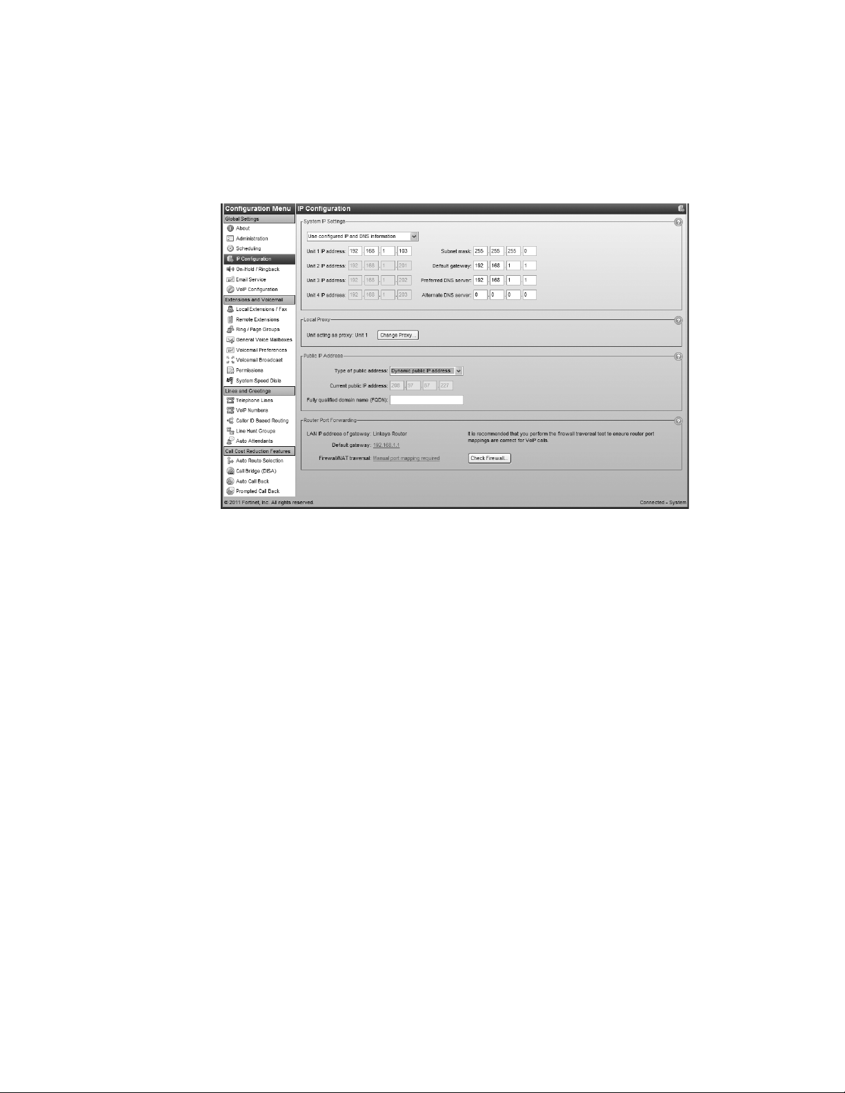
IP CONFIGURATION
The IP Configuration page allows you to set up the system for Internet communications. The
Internet can be used for external IP extensions, a VoIP network, a subscription to a VoIP service,
and remote configuration.
1. Select the IP Configuration page.
System IP settings
The System IP Settings area shows IP addresses. By default, Obtain IP and DNS information
automatically is selected and the area shows IP addresses from the router.
1. Change Obtain IP and DNS information automatically to Use configured IP and DNS
information in order to lock in the IP addresses.
2. In some cases, the System IP Settings area may be blank because your router has not
delivered the IP addresses. If so, enter the following IP addresses from your
LAN administrator:
a) Enter a static IP address for each unit in the Unit IP address boxes.
b) Enter the Subnet mask for the LAN. This address determines the subnet the unit IP
addresses belong to.
c) Enter the IP address of the Default gateway on your network. A gateway is a hardware
device that connects the office network to the Internet. The router may act as
default gateway.
d) Enter the IP address of the Preferred DNS server. DNS is a service used to resolve a domain
name to an IP address. The router may act as DNS server.
e) If applicable, enter the IP address of the Alternate DNS server.
CONFIGURATION 15
Page 28

Local proxy
If your system has multiple units, the Local Proxy area displays and allows you to change the
unit acting as local proxy. The local proxy handles Internet communications for the system. It
establishes connections across the Internet, and then routes Internet data to and from each
unit. The lowest numbered unit acts as local proxy by default.
The router must map the SIP, TFTP and HTTP ports to the local proxy. See Router port forwarding
on page 17.
1. If necessary, click the Change Proxy button. The Change Proxy window appears.
2. Select the unit.
Public IP address
The Public IP Address section allows you to set up Internet parameters so the system can
communicate with other locations over the Internet.
1. Set the Type of public address. Choices are:
• Dynamic public IP address — This is the default setting. Your ISP (Internet Service
Provider) will assign different public IP addresses to your location. The system will check
its public IP address every five minutes. When the public IP address changes, the system
will automatically use the new one. This allows it to manage VoIP calls properly.
• Static public IP address — A static IP address is fixed. Your ISP assigns the static IP
address. If this location will have the SIP server for a multi-branch VoIP network, we
recommend using a static IP address.
If Static public IP address is selected, the window allows you to enter the Current public
IP address, and disables the Public IP address-checker server name box.
2. If you selected Dynamic public IP address, enter the Public domain name. A public domain
name is only required if this location is the SIP server for a multi-branch VoIP network, or
has external IP extensions.
A DDNS (Dynamic Domain Name Service) provider such as www.dyndns.com can create a
public domain name to resolve to your IP address, so your multi-branch VoIP network or
external IP phones will continue to work when the IP address changes.
If you are using DDNS, ensure your router supports your DDNS service, and configure it to
update the DNS servers.
If your router does not support DDNS, download one of the applications specified on
www.dyndns.com. To update the DNS servers, the application needs to run on a PC
connected to the same LAN as the system.
3. If you selected Static public IP address, enter the Current public IP address from your ISP.
Leave the Public domain name box blank.
CONFIGURATION 16
Page 29
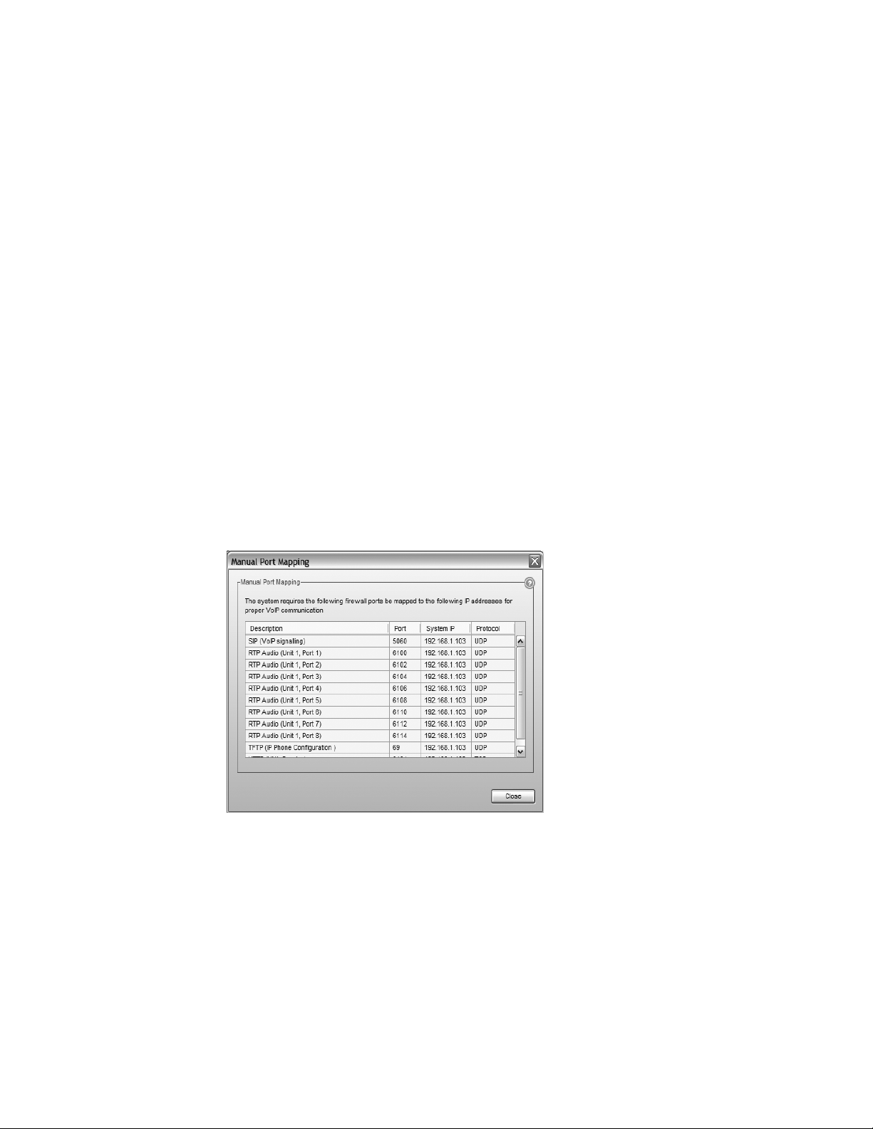
If the unit is not behind a router, or if a private virtual network is used, the public IP
address should be set to the local IP address of the unit acting as local proxy.
Note that it will take up to one minute for the new static public IP address to take effect.
Router port forwarding
The Router Port Forwarding area displays the type of gateway device (i.e. the type of router), the
IP address of the gateway (i.e. router), and whether router configuration is required.
A router is a gateway between the local area network and the Internet. Most routers have a
firewall to block unwanted data from the Internet. For voice data to reach the system through
the firewall, port forwarding is required. Port forwarding allows the router to map ports to the IP
addresses of the units. Valid Internet data will use the ports to go through the firewall to the
units.
If you are setting up external IP extensions, a multi-branch VoIP network, or a VoIP service that
doesn’t handle port forwarding, port forwarding is required.
If port forwarding is required, and your router supports uPNP (Universal Plug and Play), ensure
uPNP is enabled. The system will use uPNP to automatically set up port forwarding, and the
Automatic (uPNP Enabled) link will appear. No router configuration is required.
If port forwarding is required but your router doesn’t support uPNP, or automatic port
forwarding doesn’t work, the Manual Port Mapping Required link will appear. You will need to
configure the router as described below.
1. If required, click the Manual port mapping required link. The Manual Port Mapping
window appears. It lists the packet type, port number, IP address and protocol of each
required port.
2. To access the router configuration:
a) Click the link containing the IP address of the gateway. The default browser starts, and
prompts you for the router’s user name and password.
b) Enter the router’s user name and password. The browser shows a setup screen.
c) Navigate to the screen used to set up port forwarding. See your router documentation.
CONFIGURATION 17
Page 30

d) Set up port forwarding using the information from the Manual Port Mapping window.
See your router documentation for instructions on how to map ports. For information on
configuring routers and mapping ports, visit http://www.portforward.com/english/
routers/port_forwarding/routerindex.htm.
3. To check the status of each port through the firewall, click Check Firewall. The Firewall
Test window appears.
4. Select the services you want to check.
5. Click Test Ports. The system will check the ports of the selected services.
Configuring the router manually
If you cannot access the router configuration through the IP Configuration page, configure the
router manually.
1. Open the router configuration and navigate to the screen used to set up port forwarding.
See your router documentation.
2. In the Management Software on the IP Configuration page, click the Manual Port Mapping
Required link.
3. Map the port indicated for SIP (VoIP) signaling.
If required, you can map a different port. Select Troubleshooting > VoIP and enter the port
in the SIP signalling port field.
CONFIGURATION 18
Page 31

Map the rest of the ports to the IP addresses indicated in the Manual Port Mapping window.
If required, you can map different ports. Select Troubleshooting > VoIP.
4. Map ports 9393, 8485 and 8486 (Type: TCP) to the unit acting as local proxy to allow remote
configuration of the system.
5. If available, enable Quality of Service (QoS) to give voice traffic priority over data.
6. Save the configuration to the router.
CONFIGURATION 19
Page 32

ON-HOLD/RINGBACK
Music on hold plays when a caller is on hold, or is being transferred to an extension. The system
plays a double beep tone or ringback tone by default, but you can have it play music or a
recorded message instead.
The system can play music on hold from an internal .wav file or from an external audio source.
An external audio source is a CD player or MP3 player. It must be connected to the MUSIC jack
on the back of each unit.
The recording time for internal music on hold, voicemail, and the auto attendants is shared on
the unit.
The On-Hold/Ringback page allows you to set up music on hold.
1. Select the On-Hold/Ringback page.
On-hold settings
The On-hold Settings area allows you to select the sound to play while the caller is on hold.
1. Select the sound to play while the caller is on hold. Choices are:
• Play “double beep” tones — Plays a “beep beep” sound.
• Play music whose source is connected to the MUSIC jack — Plays music from a CD player
connected to the MUSIC jack.
• Play music from file loaded on the system — Plays the .wav file loaded into the system.
2. If you selected Play music from file loaded on the system:
a) Obtain an 8 kHz, 8 bit, Mono, u-Law .wav file that contains the music or recorded
message.
You can also convert .mp3 and other file formats to .wav with an audio converter utility.
CONFIGURATION 20
Page 33

b) Click Load Wav file. The Select Wav File window appears.
c) Click Browse to select a .wav file. Click Load to load the .wav file into the system. The
file size and date loaded will be dispayed. Play and Stop buttons are also provided, if
you prefer to listen to the file before loading it.
d) Save the configuration to allow the music on hold to take effect.
3. Adjust the volume of music on hold.
a) Check the volume by placing a test call and going on hold.
b) Change the volume by setting the Playback volume for music file list. Choices are:
•loudest
• louder
•default
• quieter
• quietest
c) Choose File > Save.
You must save the configuration for the volume setting to take effect.
d) Repeat Steps a) to c).
Deleting a music on hold file
You can delete a music on hold file. This may be required if you need more space for voicemail
messages. In this case you can use an external audio source for music on hold, or you can
upgrade the memory capacity of the units.
1. Click Delete Wav File. The system deletes the .wav file from the unit(s).
Playing music on hold on the PA system
You can play music on hold through the PA jack.
1. Dial *80 to play or stop playing music on hold through the PA jack.
If music on hold is playing through the PA jack, and a user dials *0 to make an overhead page,
the overhead page will interrupt the music on hold. However, if the PA jack is configured for
voicemail screening, and music on hold is playing, voicemail screening will not interrupt the
music on hold. See Paging Options on page 154.
CONFIGURATION 21
Page 34

Transfer settings
The Transfer Settings area allows you to select the sound to play while the caller is being
transferred from an auto attendant or to another extension.
1. Select the sound to play while the caller is being transferred. Choices are:
• Music — Plays music on hold as configured in the On-Hold Settings area.
• Ringback — Plays the ringback tone, which is the normal sound heard when the other
person’s phone is ringing.
CONFIGURATION 22
Page 35

EMAIL SERVICE
The system can send an e-mail if a voicemail message has been left in a mailbox. The e-mail
includes the caller ID, and can include the voicemail message as an attachment.
The e-mail can optionally include links to delete or save the voicemail message. If you delete the
voicemail message, it will be removed from the system. If you save the voicemail message, the
system will change its status from “new” to “saved”. A voicemail message that is saved will no
longer activate the new message indicator on the user’s extension.
The system can send notification to up to four e-mail addresses per mailbox. For example, if a
caller leaves a message in the general mailbox for the sales group, the system can send an e-mail
to four members of the sales group.
An e-mail address can be assigned to multiple mailboxes. For example, the system can send emails to a user if callers leave messages in the user’s local extension mailbox, remote extension
mailbox or a general mailbox.
The Email Service page allows you to maintain e-mail addresses, set up the e-mail server
parameters, and test the e-mail server.
1. Select the Email Service page.
Email notification settings
The Email Notification Settings area allows you to add up to 255 e-mail addresses.
1. Select a slot for the e-mail address.
2. Enter the recipient’s Full name.
3. Enter the recipient’s Email address.
CONFIGURATION 23
Page 36

4. Select the Notification option. Choices include:
• Include voice message as attachment — Attaches the voicemail message to the e-mail as
a .wav file. The e-mail includes options to save or delete the voicemail from the system.
• Email notification only (Full length) — Does not attach the voicemail message to the e-
mail, but includes full details about the contents of the voicemail, including sender, time
sent and length, along with a talley of new and saved messages.
• Email notification only (SMS length) — Does not attach the voicemail message to the e-
mail as above, and includes the same information abbreviated to under 130 characters.
Import an email list
The Import an Email List area allows you to import e-mail addresses from a .csv file.
Each entry in the file must be formatted as follows: name,e-mail address. For example:
John Doe,john.doe@email.com
Jane Doe,jane.doe@email.com
1. Click Select File. The Import an Email List window appears.
2. Select the .csv file, and then click Open.
E-mail server settings
The Email Server Settings area allows you to set up the e-mail server parameters, include links to
delete or save the voicemail message, and test the system’s ability to send e-mail.
You will need an e-mail address to send notifications from. For best results, use an e-mail
associated with an SMTP server that supports Plain authentication.
Notification may not work properly if the SMTP server uses Microsoft Exchange Server, and/or
certain security features are enabled.
Use e-mail account information from your Internet service provider (ISP), system administrator,
or alternatively, obtain one from a compatible online e-mail provider.
CONFIGURATION 24
Page 37

1. Enter an e-mail address in the Dedicated email address for sending/receiving emails box.
When e-mail notifications arrive from the system, this e-mail address will show up in the
From field.
2. Enter the name of the Outgoing mail server (SMTP).
3. To configure authentication and server port numbers, click More Settings. The Outgoing
Email Settings window appears. See Outgoing server authentication on page 25 and Outgoing
server port numbers on page 26.
4. To include links within the e-mail notification, select the Enable delete/save messages
option checkbox. The links will allow the recipient to delete or save the voicemail message.
The e-mail notification can only include the links if the voicemail message is attached.
Deleting the voicemail message will remove it from the unit. Saving the voicemail message
will change its status from “new” to “saved”. A voicemail message that is saved will no
longer activate the new message indicator on the user’s extension.
5. Enter the name of the Incoming mail server (POP3). The name will automatically appear in
the My Outgoing Server (SMTP) Requires Authentication area.
6. To configure authentication, server port numbers and how often the system should check
the POP3 server, click More Settings. The Incoming Email Settings window appears. See
Incoming server authentication on page 26, Incoming server port numbers on page 27 and
Incoming mail server options on page 27.
Outgoing server authentication
The My Outgoing Server (SMTP) Requires Authentication area allows you to enter account
information for the outgoing server. The outgoing server is also referred to as the SMTP server. It
can have its own account information, or can use the account information from the incoming
server. The incoming server is also referred to as the POP3 server.
1. If the outgoing server requires authentication, select the My Outgoing Server (SMTP)
Requires Authentication checkbox.
2. Choose the type of authentication used by the outgoing server:
• If the outgoing server uses its own logon information, and can send e-mail without first
logging on to the incoming server:
i) Select This server requires SMTP logon information.
CONFIGURATION 25
Page 38

ii) Enter the User name of the account from the outgoing server.
iii) Enter the Password of the account from the outgoing server.
• If the outgoing server uses logon information from the incoming server, and must log on
to the incoming server before sending e-mail:
i) Select This server requires logon to incoming mail server before sending mail.
ii) Enter the name of the Incoming mail server (POP3). The name will automatically
appear in the Enable Delete/Save Messages Option area.
iii) Enter the User name of the account from the incoming server. The user name will
automatically appear in the Incoming Server Authentication area.
iv) Enter the Password of the account from the incoming server. The password will
automatically appear in the Incoming Server Authentication area.
Outgoing server port numbers
The Server Port Numbers area allows you to enter a port number for the outgoing server. This is
only required if the standard default port number cannot be used.
1. The default Outgoing mail server (SMTP) port is 25. If required, enter a different port number
ranging from 0 to 65535.
Incoming server authentication
The Incoming Server Authentication area allows you to enter the user name and password of the
account from the incoming server. The incoming server is also referred to as the POP3 server.
1. Enter the User name of the account from the incoming server. The user name will
automatically appear in the My Outgoing Server (SMTP) Requires Authentication area.
2. Enter the Password of the account from the incoming server. The password will automatically
appear in the My Outgoing Server (SMTP) Requires Authentication area.
CONFIGURATION 26
Page 39

Incoming server port numbers
The Server Port Numbers area allows you to enter a port number for the incoming server. This is
only required if the standard default port number cannot be used.
1. The default Incoming mail server (POP3) port is 110. If required, enter a different port
number ranging from 0 to 65535.
Incoming mail server options
The Incoming Mail Server Options area allows you to specify how often the unit should check the
incoming server for e-mail messages from users deleting and saving voicemail messages. The
incoming server is also referred to as the POP3 server.
1. Select the Email request interval, ranging from 2 minutes to 30 minutes.
2. To delete e-mail messages that aren’t from users (i.e. spam), select the Delete any
unrecognized inbound emails checkbox.
CONFIGURATION 27
Page 40

Testing the e-mail server settings
1. Click Test Account Settings.
2. Click Save. The system saves the configuration, then the Test Account Settings
window appears.
3. Enter an e-mail address in the Test email address box, and then click Start. The following
window shows a successful result, with each task completed.
If a task fails, the system is not able to send e-mail messages. Adjust the e-mail server
parameters accordingly:
• If Find outgoing mail server (SMTP) fails, check the SMTP server name in the Outgoing
mail server (SMTP) box.
• If Log onto outgoing mail server (SMTP) fails, check the SMTP server authentication
parameters in the Outgoing Email Settings window.
4. Ensure the e-mail address has received the test e-mail. Note that the e-mail may have been
routed to a junk or spam folder.
Managing voicemail messages
If the Notification option is set to Include voice message as attachment, the recipient can play,
save or delete the voicemail message.
1. To play the voicemail message, the recipient double-clicks the attachment. The default .wav
player opens the voicemail message.
CONFIGURATION 28
Page 41

2. To save the voicemail message, the recipient clicks Save message. The e-mail program
creates a new e-mail message with the To and Subject fields completed. The recipient sends
this e-mail message. Upon receiving the e-mail message, the system will change the status of
the voicemail message from “new” to “saved”, and the local extension will turn off the new
message indicator. However the system will not delete the voicemail message.
Note that the system allows up to 99 voicemail messages per mailbox. Once a mailbox fills
up, callers won’t be able to leave voicemail messages for that user. Therefore users should
delete voicemail messages before the mailbox fills up.
3. To delete the voicemail message, the recipient clicks Delete message. The e-mail program
creates a new e-mail message with the To and Subject fields completed. The recipient sends
this e-mail message. Upon receiving the e-mail message, the unit will delete the voicemail
message.
Setting up POP3 service with Microsoft Exchange
If your system uses Microsoft Exchange, and you wish to include voicemail messages as
attachments within the notification emails, you must set up POP3 service.
For instructions on how to download, install and configure POP3 service, refer to the Microsoft
documentation included with your version of Exchange. See http://technet.microsoft.com/en-
us/library/aa998454(EXCHG.65).aspx for more information.
Risks of enabling POP3 service
• The default configuration does not use encryption when sending the username
and password.
• Unauthorized clients can use the POP3 service.
• E-mails from users for saving and deleting voicemail messages are not stored on the
Exchange server, but are pulled through to the client (i.e. the system).
Security recommendations
1. Install the system on the same LAN as the Exchange server.
2. Follow the Microsoft procedures for tightening security.
3. The POP3 service is a virtual server. You can use the following techniques to control
incoming access to a virtual server. Refer to the Microsoft documentation included with your
version of Exchange.
• Grant or deny access using IP addresses or Internet domain names.
• Require authentication for incoming connections.
• Restrict concurrent connections.
• Set connection time-out values.
CONFIGURATION 29
Page 42

VOIP CONFIGURATION
The VoIP Configuration page allows you to set up the multi-branch VoIP profile for the SIP
server or a SIP client, and up to four service provider profiles. You can also view registrar
entries, view registration status, set codec options, and reserve VoIP lines for specific setups.
The VoIP Configuration page is only present with a VoIP-enabled system. The layout of the
page depends on whether you are configuring a multi-branch profile or a service
provider profile.
Setting up a multi-branch profile
You can set up a multi-branch profile for the SIP server or for a SIP client. The multi-branch
profile contains registration details and authentication information. The information is from the
unit acting as the SIP server for a multi-branch VoIP network.
Any VoIP-enabled unit can act as the SIP server. However a multi-branch VoIP network requires
that one (and only one) unit be configured to act as the SIP server. Systems at other locations
are configured as SIP clients.
When the SIP server is enabled and SIP clients are registered with the SIP server, all VoIP calls
within the multi-branch VoIP network contact the SIP server to resolve the destination location.
Once the destination is resolved, the call goes directly from the source to the destination.
Activate profile
1. Select the VoIP Configuration page.
2. Select Profile MB, which is for configuring the multi-branch profile.
The Activate Profile area indicates the Profile name is Multi-branch.
In the Start VoIP location numbers at: field, you can specify where the range of 50 VoIP
location numbers begins. You will not be able to use these 50 numbers for extensions, ring
groups, mailboxes or system speed dials.
Leave the Disable public IP address substitution checkbox cleared.
CONFIGURATION 30
Page 43

You can specify which codecs to use by clicking the Codec Options button. See Setting codec
options on page 37.
Provisioning details
SIP server
1. Select the This location is the Proxy/Registrar checkbox. The page enables the View
Registrar Entries button. See Viewing registrar entries on page 35.
2. If the SIP server requires a non-default SIP server registration interval, SIP signalling port,
or starting RTP port, enter the new values. See VoIP Trunking on page 158.
3. Ensure your router is set up to perform port forwarding for the SIP signalling and RTP ports.
See Router port forwarding on page 17.
SIP client
1. Leave the This location is the Proxy/Registrar checkbox cleared.
The page disables the Registrar authentication list and the View Registrar Entries button.
2. Enter the Current public IP address or Public domain name of the SIP server into the Proxy/
Registrar server name box.
If the SIP server requires a non-default SIP signalling port (i.e. if the SIP server cannot use
5060 as the SIP signalling port), specify the port number after a colon at the end of the
public IP address or public domain name (e.g. 123.45.67.89:3456).
3. Ensure your router is set up to perform port forwarding for the SIP signalling port. See
Router port forwarding on page 17.
The Provisioning Details area also allows you to view the status of registered SIP devices. See
Viewing registration status on page 36.
Authentication
The Authentication area allows you to set a username and password for the multi-branch VoIP
network if you choose to permit access exclusively to authorized devices.
1. If you are configuring the SIP server location, set Registrar authentication to Yes.
2. Enter the User/account name. All SIP clients must use this name.
3. Enter the Password. All SIP clients must use this password.
System VoIP options
VoIP Caller ID
The VoIP Caller ID area allows you to set up the source for the caller ID name for outbound VoIP
calls. The same setting is used for the multi-branch profile and all service provider profiles.
Extension names are used by default.
1. Set the caller ID information for outgoing VoIP calls:
• To use the System name from the Administration page, select Use system name in Caller
ID information for all outgoing VoIP calls.
• To use the First name and Last name from the Local Extensions/Fax page, select Use
extension names in Caller ID information for all outgoing VoIP calls.
See Caller ID settings on page 43 to select the phone number that will appear on the
other phone.
CONFIGURATION 31
Page 44

Line reservation
By default, all VoIP lines are available for external IP extensions, multi-branch VoIP network
calls, and/or service provider calls on a first-come first-served basis. You can also reserve VoIP
lines for a specific use. For example, you could set aside two lines for external IP extensions.
Reserving VoIP lines guarantees resources for a specific network. Sharing VoIP lines uses them
most efficiently.
When reserving VoIP lines for a service, the choice ranges from 1 to the number of unreserved
VoIP lines at this location. Shared means do not reserve any VoIP lines for this service. Only
unreserved lines will be available.
1. Click Reserve VoIP Lines. The VoIP Resource Reservation window appears.
2. Select the number of VoIP lines to reserve for External IP extension calls using its pull-down
menu.
3. Select the number of VoIP lines to reserve for Multi-branch VoIP network calls using its pull-
down menu.
4. Select the number of VoIP lines to reserve for VoIP service provider calls for each provider
using its pull-down menu.
CONFIGURATION 32
Page 45

Setting up a service provider profile
A service provider profile contains the settings that allow your system to register with the
provider.
Service configuration guides for certified VoIP service providers are available in the Windows
program folder under Service Configuration Guides.
1. Select the VoIP Configuration page.
2. Select a Profile (SP 1 to SP 4).
Activate profile
You can set up a service provider profile automatically or manually.
Automatic configuration
1. Select the Activate Profile checkbox.
2. The Service Provider menu offers a list of certified VoIP service providers. If your service
provider appears in the menu, click on the name. The name is then displayed in the Service
Provider field.
CONFIGURATION 33
Page 46

3. Click the Update configuration button. The essential settings for communication with the
service provider’s registration server will be completed automatically.
Note: For selected service providers in your region, a link may appear beside the Profile
Name to permit easy access to the provider’s website.
4. If you want to customize other aspects of your VoIP lines, you may do so in the System VoIP
Options area. See System VoIP options on page 31.
Account-specific and number-specific settings are not automatically configured. These must
be entered on the VoIP Numbers page.
Manual configuration
1. Select the Activate Profile checkbox.
2. Enter the Profile name. The default profile name is Service provider n (e.g. Service provider 1).
3. If your service provider requires you to register using your private IP address, select the
Disable public IP address substitution checkbox. Check with your service provider.
4. Some providers require the system to register using the username or account information
rather than the VoIP number(s) provided. If so, check the Register with authentication
username box to have the system register with the username information provided in the
VoIP numbers page. Check with your VoIP service provider if you’re uncertain which method
of registration is required
5. If your service provider requires keep alive messages, and if your router does not support
uPNP, check the Enable NAT keep alives checkbox.
CONFIGURATION 34
Page 47

a) Click Settings. The Keep Alive Settings window appears.
b) Select the method used to keep ports open. Choices are:
• Simple ping — A standard ping message that works with all SIP servers.
• Nortel ping — A ping message that works with Nortel SIP servers (e.g. Nortel
MCS 5200).
c) If necessary, change the ping frequency. The default setting is 45 seconds.
6. You can specify which codecs to use by clicking the Codec options button. See Setting codec
options on page 37.
Provisioning details
Enter the IP addresses or public domain names, as provided by the service provider, into the
following boxes. If the service provider does not specify a value, leave the box blank.
• Proxy/Registrar server name
• Registrar server name
• Outbound proxy
• Realm/domain
The View All Registrations button will allow you to confirm connection to your service
provider once you have completed the configuration of your VoIP numbers. See Viewing
registration status on page 36.
If you want to customize other aspects of your VoIP lines, you may do so in the System VoIP
Options area. See System VoIP options on page 31.
Viewing registrar entries
If you are configuring the multi-branch profile for the SIP server, the window enables the View
Registrar Entries button. Clicking the button shows the Registrar Entries window with a list
of the VoIP numbers, their IP addresses and port numbers, and the number of seconds until their
registrations with the SIP server will expire.
CONFIGURATION 35
Page 48

1. Click View Registrar Entries. The Registrar Entries window appears.
• Client lists the VoIP numbers set up within the system.
• Contact lists the address information used by the SIP server to contact the client. It is
comprised of the VoIP number, public IP address and port number.
• Expires is the amount of time, in seconds, until the client has to re-register with the
SIP server.
Viewing registration status
Clicking the View All Registrations button shows a window with a list of VoIP numbers, their
registration status, and the number of seconds until their registrations with the SIP server will
expire. This confirms the system is registered with a SIP server.
1. Click View All Registrations. The Registration status window appears.
CONFIGURATION 36
Page 49

2. Choose All Registrations or an active profile.
• Client lists the VoIP numbers set up within the system.
• Status is the registration status (Registered or Not registered).
• Expires is the amount of time, in seconds, until the client has to re-register with the
SIP server.
Setting codec options
A codec is a method of compressing and decompressing audio signals for communication across
a network. The system supports the G.729 and G.711 (µ-law or A-law) codecs for VoIP calls. If
your service provider or equipment requires specific codecs for VoIP or Fax over IP calls, you can
restrict thes ystem to use the required codec.
The Codec Options window allows you to select the codecs your system can use, specify the
preferred codec, and clear the unsupported codecs. You can specify the codecs for the multibranch profile, and for each service provider profile. External IP extensions will use the preferred
codec specified in the multi-branch profile.
1. Click Codec Options. The Codec Options window appears.
2. Select the codecs your system can use, and clear the unsupported codecs. The following
codecs are supported:
• G.729 — This codec provides good quality. It requires the least bandwidth and
accommodates the highest number of concurrent calls.
• G.711µ — This codec provides high quality and supports Fax over IP. It requires the most
bandwidth and accommodates the fewest number of concurrent calls. G.711µ is used in
North America and Japan.
• G.711A — This codec provides high quality and supports Fax over IP. It requires the most
bandwidth and accommodates the fewest number of concurrent calls. G.711A is used
worldwide outside North America and Japan.
3. Select the Preferred codec. G.729 is the default codec, which uses the least bandwidth and
accommodates the highest number of concurrent calls.
4. Set Voice activity detection (VAD). Enabling VAD reduces voice bandwidth when no speech is
detected, and reduces transmission of background noise. We recommend disabling VAD to
keep bandwidth available for speech.
CONFIGURATION 37
Page 50

LOCAL EXTENSIONS/FAX
A local extension can either be an analog extension or an IP extension.
An analog extension is a device (standard phone, cordless phone, fax machine or modem)
connected to an extension jack on the unit.
An IP extension is an IP phone connected through a network to a system. An internal IP
extension is a phone connected on the same LAN as the system. An external IP extension is a
phone connected outside the LAN. See Adding IP phones on page 59 for more information.
The Local Extensions/Fax page allows you to set up a local extension.
Local Extensions/Fax page
The Local Extensions/Fax page shows the extension type, user name, make and model, prompt
language, extension details, programmable keys, direct line access, voicemail, hotline, hunt
group permissions, caller ID, and call cascade for each local extension.
In the list of extensions on the left side of the page, manually configured IP extensions will be
shown in bold, and unregistered or disconnected extensions will be shown in red.
Before you begin, decide the number of digits you want your system to use for extensions, ring
groups, mailboxes and speed dials. You can use 3, 4 or 5-digit numbers. The default is 3. If you
want to use 4 or 5-digit numbers, you must change the System Numbering Plan setting on the
Administration page, or your extension numbers will be rejected by the system.
Numbers available per plan:
3-digit numbers: 100 to 399
4-digit numbers: 1000 to 3999
5-digit numbers: 10000 to 39999
In VoIP-enabled systems, regardless of the number of digits used, a block of 50 numbers is
allocated to VoIP location numbers. By default, the VoIP location numbers are 350 to 399. To
change the default block of VoIP location numbers, see Setting up a multi-branch profile on
page 30.
CONFIGURATION 38
Page 51

Extension tab
1. Select the Local Extensions/Fax page.
2. Click Add.
3. In the Add User / Extension dialog box, select the Extension type. Choices are Regular
phone or fax and IP Extension. Regular phone or fax allows you to set up an analog
extension.
4. In a multi-unit system, select the unit the extension will be associated with. This unit will
hold the voicemail for the extension. For analog extensions, this must be the unit that the
analog phone is plugged into.
5. Analog extensions: select the jack the analog phone is plugged into. Click Next.
CONFIGURATION 39
Page 52

6. Enter the user’s First name and Last name. The names are used in the dial-by-name directory
and caller ID.
7. Enter the Extension number.
8. Select the Manufacturer.
We strongly recommend you only use supported IP phones. However, if you have an
unsupported IP phone, you can select Other. Other IP phones that support the G.711 codec
(µ-law or A-law) may work with the system, but some features may not work. As the system
cannot enable special features, or customization of these IP phones, further configuration
will be limited to the programmable options on the phone itself.
9. Select the phone Model. Supported models and manufacturers vary by market.
10. If you’re setting up an IP phone, enter the MAC address of the phone. You can click Select to
choose from addresses of phones connected to the system, or enter the MAC address
manually. The MAC address is printed on the bottom of the phone and on the phone’s
shipping box.
11. Click Finish.
The information you configured now appears in the Extension tab, and you can edit it directly
there if you need to make changes. Select any extension in the menu under the Add and
Remove buttons to access the configuration details.
In the Extension section, you can select the language for prompts heard by the user of the
extension in the System prompt language list.
The Voic email tab is now visible for each extension. See Voicemail tab on page 52.
The Additional Settings window enables you to set up or customize access to lines or hunt
groups for outbound calls, designate the extension as a hotline, select CallerID display options,
etc.
CONFIGURATION 40
Page 53

Direct line access
The Direct Line Access area allows you to select the hunt group that the local extension will use
automatically. When an analog phone goes off-hook or a number is dialed on an IP phone, the
system will automatically find an available line within that hunt group.
Example: You have a fax machine connected to the local extension and don‘t want to reprogram
the speed dial numbers with hunt group numbers. Enable direct line access and select the hunt
group. As soon as the fax goes off-hook, it finds an available line within the line hunt group.
1. Click Additional Settings. The Additional Settings window appears.
2. Select the Direct Line Access tab.
3. Select the Use direct line access on checkbox. The window enables the list of line
hunt groups.
4. Select the hunt group.
Note: When using direct line access, you hear the telephone company dial tone when you
pick up the handset. You do not hear the internal dial tone. The following features are only
available from the internal dial tone:
•Intercom calls
• System speed dial numbers
• Calling the receptionist
• Attaching an account code
• Intercom paging
•Group paging
• Overhead paging
• Hunt groups
• Stutter dial tone for new voicemail
• Voicemail retrieval/access
• Entering command mode
•Call pickup
• Retrieving a parked call
• Do Not Disturb functions
To obtain an internal dial tone on an analog extension that is set for direct line access, pick
up the handset, and then press Flash or Recall. On an IP extension, press **, and then dial
the number or function.
CONFIGURATION 41
Page 54

Hotline access
The Hotline Access area allows you to select the resource that the extension will connect to. This
restricts the extension to one special task, and you cannot use the extension for any
other purpose.
An analog phone, or a 350i, 450i or 550i IP phone will automatically connect to the resource
when you lift the handset, or press the speaker or headset button. Other IP phones do not
support hotline access.
1. Click Additional Settings. The Additional Settings window appears.
2. Select the Hotline Access tab.
3. Select the action in the Connect to the following resource list. Choices are:
• None Selected — Does not automatically connect to a resource.
• go to voicemail — Connects to the selected voicemail.
• go to local extension — Connects to the selected local extension.
• go to remote extension — Connects to the selected remote extension.
• go to ring group — Connects to the selected ring group.
• go to auto attendant — Connects to the selected auto attendant.
• go to VoIP location — Connects to the selected VoIP number within the multi-branch
VoIP networ k.
4. Select the resource. Depending on the action, resources are voice mailboxes, extensions,
auto attendants, or VoIP numbers within the multi-branch VoIP network.
CONFIGURATION 42
Page 55

Hunt group permissions
The Hunt Group Permissions area allows you to select the hunt groups that the extension can
use. You can restrict an extension’s access to specific hunt groups. Each extension has access to
all hunt groups by default.
1. Click Additional Settings. The Additional Settings window appears.
2. Select the Hunt Group Permissions tab.
3. Set the checkboxes in the Hunt Group Permissions area to control access to the hunt groups.
Select a checkbox to grant access to the hunt group, or clear the checkbox to remove access.
4. If 3-Way Calling/Conference is selected in the Telephone Lines page, you can select the
Allow the use of Same Line Connect (Dial Hunt Group 80) checkbox. If this is selected, the
user can transfer a call to a remote extension using the same telephone line that the caller is
on. The user dials Flash or Recall, remote extension, and then Flash 4 or Recall 4. The
telephone company puts the caller on hold, and the system uses the same telephone line to
try the remote extension.
Caller ID settings
The Caller ID Settings area allows you to select the phone number that will appear on the other
phone when the local extension is used to make a VoIP call.
1. Click Additional Settings. The Additional Settings window appears.
CONFIGURATION 43
Page 56

2. Select the Caller ID Settings tab.
3. Set the Phone number used for multi-branch VoIP Caller ID list to the phone number that
should be displayed during a call on the multi-branch VoIP network.
4. Set each Caller ID used for Service Provider list to the phone number that should be displayed
during a call through the VoIP service provider.
Choices include Default VoIP number, and the VoIP numbers set up in the VoIP Numbers page. If
Default VoIP number is selected, the phone number associated with the VoIP line is used. This
selection makes the most sense if your VoIP numbers have been configured to handle all
inbound calls the same way.
See System VoIP options on page 31 to select the name that will appear on the other phone.
Regular extension details
If you set Extension type to Regular phone or fax, the Regular Extension Details area is enabled.
You can edit the unit number and jack to which the extension is connected.
IP extension details
If you set Extension type to IP extension, the IP Extension Details area is enabled.
Once you save the configuration and reboot the IP phone, the system will configure the IP
phone. Status will change to Registered, and the IP address of the phone will appear.
If you connected a proprietary IP phone to the LAN and used it to select an extension number,
the Location and MAC address for that extension will be complete.
CONFIGURATION 44
Page 57

1. Set the Location of the phone. Choices are:
• Internal — An internal IP extension is located within the office, and is connected to the
same LAN as the unit.
• External — An external IP extension is located outside the office, and is connected to
the unit via Internet. A VoIP-enabled unit is required.
• Both — The phone can be used as an internal or external IP extension. A VoIP-enabled
unit is required. This is available for the Counterpath eyeBeam softphone only.
Warning: Using an external IP extension to call an emergency service number will not send
the correct address to the emergency operator. We strongly recommend that you apply a
warning label to any external IP extension stating:
If an emergency call is made from this phone, you must provide your address to the
emergency operator.
2. If you set Location to External, select the Time zone that matches the location of the
IP phone.
3. Use one of the procedures below to identify the IP phone, depending on the make
and model.
Configuring IP phone keys
1. If the Configure Keys button is visible and active, you can click it to set up the actions of
your phone’s keys. See About programmable function keys on page 62 for further
instructions.
2. Choose File > Save. The system will create a configuration file that the phone will download
when the phone is restarted.
Setting handset ID for 850i or 860i phones
1. Select the Handset ID for the extension. Use the handset name on the handset screen.
2. Choose File > Save. The system will create a configuration file that the phone will download
when the phone is restarted.
Counterpath or other IP phone
1. Enter the Username and Password. The default settings are user[extension number] and
pass[extension number]. These are used to manage calls between systems and the IP
extension and must match the username and password of the IP phone. Change only
if required.
About call cascades
The Call Handling area allows you to set up call cascades for a local extension. A call cascade
routes a call to an alternative or a series of alternatives when the target extension doesn't
answer. You can set up different call cascades for Mode 1 and Mode 2.
For example, if a call reaches your desk when you’re away, it can be sent to another local
extension. If that extension isn’t answered, the call can be routed to your cell phone. If you
don’t answer your cell phone, the call can go to your voicemail.
Note that the system can be configured to ignore the call cascade for an unanswered intercom
call, or for an unanswered transferred call. See Transfer Preferences on page 154.
CONFIGURATION 45
Page 58

Setting up call handling
Busy call cascade
The busy call cascade is used when the extension is busy.
1. Select the Mode 1 tab or the Mode 2 tab.
2. Select the Busy tab.
3. Set up the first alternative.
a) Select the action in the If extension is busy list. Choices are:
• go to voicemail — Transfers the call to the selected voicemail.
• go to local extension — Attempts to transfer the call to the selected local extension.
• go to remote extension — Attempts to transfer the call to the selected
remote extension.
• go to ring group — Attempts to transfer the call to the selected ring group.
• play announcement — Plays the selected announcement.
• invoke call waiting — Notifies the user that a caller is attempting to reach them.
• go to auto attendant — Routes the call to the selected auto attendant.
• queue at extension — Transfers the call to the local extension’s call queue.
• go to VoIP location — Attempts to transfer the call to the selected VoIP number within
the multi-branch VoIP network.
• play busy tone — Plays a busy tone in the caller’s phone.
• hang up — Disconnects the telephone line.
b) Select the resource, if applicable.
c) If you selected queue at extension, the caller will hear a prompt each time the reminder
timer expires. The prompt says “If you wish to continue holding, please remain on the
line. To leave a voicemail message, press 1”. You can set the duration of the reminder
timer, to control how often the caller hears the prompt. See Call Reminders on page 157.
i) Choose Options > Call Reminders. The Call Reminder Timers window appears.
ii) Set the Queue options reminder timer.
CONFIGURATION 46
Page 59

4. If permitted, set up the second alternative.
a) Set the If busy or not answered after list to the number of rings to try the first
alternative. Choices range from 1 to 9.
b) Set the action.
c) Select the resource, if applicable.
5. If permitted, set up the third alternative.
a) Set the If busy or not answered list to the number of rings to try the second alternative.
Choices range from 1 to 9.
b) Set the action. Choices are:
• go to voicemail
• go to auto attendant
• play announcement
•hang up
c) Select the resource, if applicable.
No answer call cascade
The no answer call cascade is used when the extension is not answered.
1. Select the Mode 1 tab or the Mode 2 tab.
2. Select the No Answer tab.
3. Set up the first alternative.
a) Set the If this extension is not answered after list to the number of rings to try the
extension. Choices range from 1 to 9.
CONFIGURATION 47
Page 60

b) Select the action. Choices are:
• go to voicemail
• go to local extension
• go to remote extension
• go to ring group
• play announcement
• go to auto attendant
• go to extended ringing
• go to VoIP location
•hang up
c) Select the resource, if applicable.
4. If permitted, set up the second alternative.
a) Set the If busy or not answered after list to the number of rings to try the first
alternative. Choices range from 1 to 9.
b) Set the action. Choices are:
• go to voicemail
• go to local extension
• go to remote extension
• go to ring group
• play announcement
• go to auto attendant
• go to VoIP location
•hang up
c) Select the resource, if applicable.
5. If permitted, set up the third alternative.
a) Set the If busy or not answered after list to the number of rings to try the second
alternative. Choices range from 1 to 9.
b) Set the action. Choices are:
• go to voicemail
• go to auto attendant
• play announcement
•hang up
c) Select the resource, if applicable.
CONFIGURATION 48
Page 61

Answered call cascade
The answered call cascade is used to enable call screening, typically for cell phone remote
extensions.
1. Select the Mode 1 tab or the Mode 2 tab.
2. Select the Answered tab.
3. Set the When a call is answered list. Choices are:
• stay connected — Transfers the call to the extension. This option disables the remaining
controls in the tab. This is the default.
• play caller’s name first — Performs a screened transfer. The caller is prompted to say his
or her name. When the user answers the phone, the system plays the caller’s name, and
prompts the user to accept the call. If the user accepts the call by pressing #, it gets
connected. If the user rejects the call by pressing * or hanging up, the call is routed to
the first alternative.
4. Set up the first alternative.
a) Set the If a call is rejected from this extension action.
b) Select the resource, if applicable.
5. If permitted, set up the second alternative.
a) Set the If busy or not answered after list to the number of rings to try the first
alternative. Choices range from 1 to 9.
b) Set the action.
c) Select the resource, if applicable.
6. If permitted, set up the third alternative.
a) Follow the same steps as the second alternative.
CONFIGURATION 49
Page 62

Do not disturb cascade
The do not disturb call cascade is used when the extension is in Do Not Disturb mode.
1. Select the Mode 1 tab or the Mode 2 tab.
2. Select the Do Not Disturb tab.
3. Set up the first alternative.
a) Set the If do not disturb is on for this extension list. Choices are:
• go to voicemail
• go to local extension
• go to remote extension
• go to ring group
• play announcement
• go to auto attendant
• go to VoIP location
•hang up
b) Select the resource, if applicable.
4. If permitted, set up the second alternative.
a) Set the If busy or not answered after list to the number of rings to try the first
alternative. Choices range from 1 to 9.
b) Set the action.
c) Select the resource, if applicable.
5. If permitted, set up the third alternative.
a) Set the If busy or not answered after list to the number of rings to try the second
alternative. Choices range from 1 to 9.
b) Set the action.
c) Select the resource, if applicable.
CONFIGURATION 50
Page 63

Setting do not disturb mode
The user can toggle Do Not Disturb mode by dialing *62 on their local extension.
The administrator can enable or disable Do Not Disturb mode for a local extension by phone.
1. Pick up a local extension, or remotely call the system.
2. Enter command mode by pressing # on an analog extension phone, or *55# on an IP phone
(other brands may use *55 Send or *55 Dial).
3. Enter the system password, followed by #.
4. Enter one of the following commands:
• #60 [Local extension] # to disable Do Not Disturb mode for the local extension.
• #61 [Local extension] # to enable Do Not Disturb mode for the local extension.
5. Press * to exit command mode.
Ignoring call cascades for unanswered intercom calls
An intercom call is an internal call from a local extension to another local extension, remote
extension or ring group. If the call is unanswered, the call follows that extension’s call cascade
by default. However you can configure the system to ignore call cascades for unanswered
intercom calls. See Internal Calls on page 159.
1. Choose Options > Internal Calls. The Intercom Calls Options window appears.
2. To have the system ignore call cascades for unanswered intercom calls, clear the Intercom
calls follow cascade settings checkbox.
• If the extension is busy, the caller will hear a busy tone.
• If the extension is not answered, it will continue to ring.
• If a local extension has call screening enabled, the caller won’t be prompted for their
name. However, if a remote extension or ring group has call screening enabled, call
screening will occur. If the call is rejected, the system will follow the call cascade.
• If a local extension has do not disturb mode enabled, it won’t ring, and the caller will
hear “I’m sorry, that extension is unavailable at this time. Do not disturb on. Please try
again later”. If all the local extensions in a ring group have do not disturb mode
enabled, the caller will hear a busy tone.
Ignoring call cascades for calls transferred from local extensions
A user at a local extension can transfer a call to another local extension, remote extension or
ring group. If the call is unanswered, the call follows that extension’s call cascade by default.
However you can configure the local extensions, remote extensions and/or ring groups to ignore
their call cascades for calls that are transferred from a local extension but unanswered. In this
case, the system will ring back the local extension that transferred the call, reconnecting the
user with the caller they transferred.
CONFIGURATION 51
Page 64

1. Choose Options > Transfer Preferences. The Transfer Preferences window appears.
2. Select the appropriate tab.
• To configure call handling for calls transferred to local extensions, select the To Local
Extension tab (see To local extension tab on page 154).
• To configure call handling for calls transferred to remote extensions, select the To
Remote Extension tab (see To remote extension tab on page 155).
• To configure call handling for calls transferred to ring groups, select the To Ring Group
tab (see To ring group tab on page 156).
3. Select the call handling setup for calls transferred from a local extension but unanswered:
• To have the system ring back the local extension that transferred the call, select Ring
back the extension that transferred the call.
• To use the Busy call cascade, select Perform the Busy action.
• To use the No Answer call cascade, select Perform the No Answer action.
Voicemail tab
The Voicemail tab allows you to activate the voice mailbox or announcement, load the greeting, set
the action to perform if the caller dials 0 (9 in some regions), and set up voicemail notification.
By default, each local extension mailbox is activated.
The recording time for internal music on hold, voicemail, and the auto attendants is shared on
the unit.
Note that the system allows up to 99 voicemail messages per mailbox. Once a mailbox fills up,
callers won’t be able to leave voicemail messages for that user. Therefore users should delete
voicemail messages before the mailbox fills up.
1. Select the Local Extensions/Fax page.
CONFIGURATION 52
Page 65

2. Select the Voicemail tab.
Note: Depending on the region, an operator may be dialed using 9 or 0.
3. If necessary, select the Activate Voice mailbox checkbox.
Mailbox greeting
The Mailbox Greeting area allows you to load a greeting, and configure the voice mailbox as a
mailbox or announcement. Note that you can also record a greeting using a local extension
connected to the unit.
The greeting should tell the caller to dial 0 (9 in some regions) to perform the action selected in
Caller options, if you will configure these options.
1. To record a greeting:
a) Pick up a local extension connected to the unit.
b) Press ** <extension number>, and then follow the prompts to record a greeting.
2. To load a greeting:
a) Obtain an 8 kHz, 8 bit, Mono, u-Law .wav file that contains the greeting. The maximum
file size is 5 minutes.
b) Click Load Greeting. The Select Wav File window appears.
CONFIGURATION 53
Page 66

c) Click Browse to select a .wav file. Click Load to load the .wav file into the system. Play
and Stop buttons are also provided, if you prefer to listen to the file before loading it.
3. To configure the voice mailbox as a mailbox, leave the Play announcement only checkbox
cleared. The unit activates the greeting and the mailbox, and enables all the controls on the
page. The caller will hear a greeting, and will be able to leave a message in the mailbox.
4. To configure the voice mailbox as an announcement, select the Play announcement only
checkbox. The unit activates the greeting, disables the ability to leave a message, and
disables the Notification Settings area. The caller will hear a greeting, but will not be able to
leave a message.
Caller options
The Caller Options area sets the action to perform if the caller dials 0 (9 in some regions) during
the voicemail greeting. You can set up different actions for Mode 1 and Mode 2.
1. For each mode, select the action to perform if a caller dials 0 (9 in some regions).
Choices are:
• go to auto attendant
• go to local extension
• go to remote extension
• go to ring group
• go to voicemail
• play announcement
• dial-by-name directory
•perform no action
2. Depending on the action, enter the resource.
Notification options
The Notification Options area allows you to set up voicemail notification, which tells the user if a
caller leaves a message. The system can:
• Notify up to four users by e-mail, with the voicemail message included as an attachment.
• Notify a user by phone and/or pager.
• Activate the message waiting light and stutter dial tone on one or more local extensions.
• Perform voicemail screening by routing audio to the PA jack.
Setting up notification by e-mail
Note that e-mail notifications might be routed to the user’s junk or spam folder. Advise each
user to set up their e-mail accounts to allow e-mail notifications to go to their inboxes.
1. Set up the e-mail addresses. See Email Service on page 23.
CONFIGURATION 54
Page 67

2. Select the Email Notification tab.
3. Select the Enable email notification checkbox.
4. Click Edit. The Select Email Addresses window appears.
5. Select up to four e-mail addresses.
Setting up notification by phone
1. Select the Cell/Pager Notification tab.
2. Select the Enable remote phone notification checkbox.
3. Enter the Phone number. Enter the number as you would normally dial it (i.e. without the
hunt group number). You can enter digits 0–9, space, dash, comma, # and *. A comma
pauses dialing for two seconds.
CONFIGURATION 55
Page 68

4. Click Notification Settings. The Notification Settings window appears.
5. Select the notification setting. Choices are:
• Select the first option to have the system play the notification message once, when the
phone is answered. It will then consider notification to be successful. Note that if there
is any answer other than a busy tone, (e.g. voicemail, “subscriber not available”
message, etc.) It will consider notification to be successful.
• Select the second option to have the system repeat notification until the user either
dials * to skip the message, or dials # to play the message. It will only consider
notification to be successful once the user acknowledges notification by dialing a key.
This is useful for cell phones where the telephone company plays a “subscriber not
available” message instead of a busy tone.
Setting up notification by pager
1. Select the Cell/Pager Notification tab.
2. Select the Enable pager notification checkbox.
3. Enter the Pager number. Enter the number as you would normally dial it (i.e. without the
hunt group number). You can enter digits 0–9, space, dash, comma, # and *. A comma
pauses dialing for two seconds.
4. Enter the Numeric message that will appear on the user’s pager.
Setting up the notification options
1. Click Configure Notification Options. The Notification Settings window appears.
2. Select the hunt group the system will use to phone or page the user.
3. Select the number of rings before aborting attempt, ranging from 1 ring to 9 rings.
4. Select the number of attempts the system should make, ranging from once to 10 times.
CONFIGURATION 56
Page 69

5. Select the interval between attempts, ranging from 5 minutes to 60 minutes.
6. Select the modes when the system will perform notification. Choices include Mode 1, Mode 2
and All Modes.
Setting up message waiting light activation
If a local extension has a new message in its voice mailbox, the system activates notification on
that extension, by default. The user hears a stutter dial tone when they pick up the handset
(not applicable to the 850i or 860i phone models). If the extension supports an FSK message
waiting indicator (not applicable to IP phones), the message waiting light flashes. Some phone
models support a message waiting counter. The display on the extension shows the number of
new messages stored in the mailbox(es) associated with that extension.
You can also have the system activate notification on a local extension if a message is received
in any other local extension, remote extension, or general mailbox.
1. Select the Message Waiting Light tab.
2. Click the Edit button. The Message Waiting Indication window appears.
3. Select the extensions.
CONFIGURATION 57
Page 70

Voicemail screening
The system can be configured to perform voicemail screening in addition to overhead paging. In
this case it will route audio to the PA jack when a caller leaves a voicemail message or a user
accesses a voice mailbox. See Paging Options on page 154.
NOTE: If a user has dialed *80 to route music on hold through the PA jack, voicemail screening
will not interrupt music on hold.
1. Choose Options > Paging. The Paging Options window appears. The PA output option is set
to PA Announcements by default, which allows overhead paging but not voicemail screening.
2. To enable voicemail screening, select Voicemail screening. The system will continue to allow
overhead paging, but will also perform voicemail screening.
CONFIGURATION 58
Page 71

ADDING IP PHONES
This section describes how to configure an IP phone as a local extension. An IP phone can be
internal (located in the office) or external (located outside the office).
We recommend our IP phones and supported third-party IP phones for ease of configuration.
The system currently supports the following third-party IP phones:
• Polycom IP 301, IP 320, IP 330, IP 430, IP 501, IP 550, IP 601 and IP 650. See Adding
Polycom IP Phones on page 73.
• Grandstream GXP2000 and GXP2020. See Adding Grandstream IP phones on page 77.
• Counterpath eyeBeam softphone. See Adding Counterpath IP phones on page 81.
OVERVIEW
For each supported IP phone, this guide describes how to:
• Add the IP phone to the system configuration.
• Configure the router, if setting up an external IP extension.
• Connect the IP phone to the network.
• Check and update the IP phone firmware version, if required.
• Program the IP phone.
Refer to Adding Other IP Phones on page 85 for configuration information of non-supported
IP phones.
ADDING 350i, 450i AND 550i IP PHONES
Connecting the IP phone to the network
1. Connect a network cable between the LAN port on the phone (marked ) and your network
(i.e. router or LAN connection). The phones also have a PC port. The PC port can be used to
connect the PC to the network if only one network connection is available.
2. Connect power to the phone, either using the optional power adapter or an 802.3af PowerOver-Ethernet (POE) source.
If the phone is connected to the same network as the system, and an extension has been
configured with the phone’s MAC address, the system will automatically register and
configure the phone. When complete, the phone will display the extension name and
extension number.
If the phone is connected to the network and no extension has been configured with the
phone’s MAC address, the phone will bootup with the model number showing in the display.
Adding the extension to the system
1. Launch the Management software.
2. Select the Local Extensions/Fax page.
CONFIGURATION 59
Page 72

3. Click the Add button. The Add User / Extension window appears.
4. Set the Extension type to IP Extension.
5. In a multi-unit system, select the unit the extension will be associated with. This unit will
hold the voicemail for the extension. Click Next.
6. Enter the user’s First Name and Last Name. The names are used for caller ID and the dial-by-
name directory.
7. Assign an Extension number.
8. If necessary, select the Manufacturer, and then select the Model.
CONFIGURATION 60
Page 73

9. Enter the MAC address of the phone:
• You can select the Phone MAC Address from a list of automatically-detected phones
connected to your LAN. To use this method:
i) Click the Select button. A MAC Selection window appears and lists IP phones of the
selected type.
ii) Select the MAC address of the IP phone associated to the extension, and then click
Select.
• You can enter the Phone MAC Address manually. This is the required method if you are
setting up an external IP extension. The MAC Address is a 12-digit alphanumeric string
located in the barcode on the bottom of the phone and the box the phone came in.
Click Finish.
10. In the Extension tab, select the language for prompts heard by the user of the extension in
the System Prompt Language list. Setting the prompt language will also change the language
for text displayed on the phone itself.
11. Choose File > Save. The system will create a configuration file that the phone will download
when the phone is restarted.
CONFIGURATION 61
Page 74

IP extension details area
1. Set the Location. Choices are:
• Internal — The phone is an internal IP extension located within the office, and is
connected to the same LAN as the unit.
• External — The phone is an external IP extension located outside the office, and is
connected to the unit over the internet. See External IP extensions on page 85.
Warning: Calls to an emergency service number using an external IP extension will not send
the correct address to the emergency operator. We strongly recommend that you apply a
warning label to any external IP extension stating:
If an emergency call is made from this phone, you must provide your address to the
emergency operator.
2. If you set Location to External, select the Time Zone that matches the location of the IP
phone.
About programmable function keys
The 350i has 6 programmable functions keys, the 450i has 10 programmable keys, and the 550i
has 22 programmable keys. The keys allow the user to access features, and to monitor and
engage lines, extensions and queued calls (i.e. line appearance).
Note that the keys cannot be programmed if the extension has hot line access enabled. In this
case, the phone will automatically connect the pre-configured resource (external number,
extension etc.)
Programming 350i function keys
1. Click Configure Keys. This button is enabled if the IP Extension Details area is complete.
The 350i window appears.
2. For each key, select the Function and the Resource (if applicable). The function keys can be
assigned for Line Appearance, Extension Appearance, Queue Appearance, Voicemail, Do Not
Disturb (DND), Speed Dial, Park, Unpark, Call Pickup (any or specific extension), Group Page,
Overhead Page, Phone Book configuration, or User Defined (phone). For further details, see
Phone programmable key functions on page 71.
CONFIGURATION 62
Page 75

3. Optionally, you can apply predefined key assignments from a template file using the Open
Template button. See Using a key assignment template on page 63.
If necessary, use the Default button to restore the keys to their default settings.
4. Use the Print button to print a label showing the key configuration. Cut out the printed
label and insert it in the phone next to the key lights.
5. Your key assignments can be saved as a template for programming additional phones. See
Saving a key assignment template on page 63.
Saving a key assignment template
You can use the template file as a starting point for the key assignments for another extension.
After setting up the key assignments:
1. Click Save Template As to save the key assignments to a template file. The Save Template
As window appears.
2. Enter the filename of the template file, and then click Save.
Using a key assignment template
1. To display the key assignments from a template file, click Open Template. The Open
Template window appears.
2. Select the template file, and then click Open Template.
Programming 450i function keys
1. Click Configure Keys. This button is enabled if the IP Extension Details area is complete.
The 450i window appears.
2. Select up to 10 softkey options. For each option, select the Function and the Resource (if
applicable). The function keys can be assigned for Line Appearance, Extension Appearance,
Queue Appearance, Voicemail, Do Not Disturb (DND), Phone Book access, Speed Dial, Park,
Unpark, Call Pickup (any or specific extension), Group Page, Overhead Page, or User Defined
(phone). For further details, see Phone programmable key functions on page 71.
CONFIGURATION 63
Page 76

If the phone has 50e expansion modules installed, use the pull-down menu to select the
number of modules installed. Select the tab associated to each module and configure the
keys.
3. Optionally, you can apply predefined key assignments from a template file using the Open
Template button. See Using a key assignment template on page 63.
If necessary, use the Default button to restore the keys to their default settings.
4. Use the Print button to print a label showing the key configuration. Cut out the printed
label and insert it in the phone next to the key lights.
5. Your key assignments can be saved as a template for programming additional phones. See
Saving a key assignment template on page 63.
Programming 550i function keys
1. Click Configure Keys. This button is enabled if the IP Extension Details area is complete.
The 550i window appears.
2. Select up to 22 softkey options. For each option, select the Function and the Resource (if
applicable). The function keys can be assigned for Line Appearance, Extension Appearance,
Queue Appearance, Voicemail, Do Not Disturb (DND), Phone Book access, Speed Dial, Park,
Unpark, Call Pickup (any or specific extension), Group Page, Overhead Page, or User Defined
(phone). For further details, see Phone programmable key functions on page 71.
If the phone has 50e expansion modules installed, use the pull-down menu to select the
number of modules installed. Select the tab associated to each module and configure the
keys.
CONFIGURATION 64
Page 77

3. Optionally, you can apply predefined key assignments from a template file using the Open
Template button. See Using a key assignment template on page 63.
If necessary, use the Default button to restore the keys to their default settings.
4. Use the Print button to print a label showing the key configuration. Cut out the printed
label and insert it in the phone next to the key lights.
5. Your key assignments can be saved as a template for programming additional phones. See
Saving a key assignment template on page 63.
Programming the 350i, 450i or 550i IP phone as an external IP extension
If you are setting up an external IP extension, you must ensure there is a communication path
over the network between your phone and your system. See Configuring the router on page 85.
Program the following settings into the phone. On the phone:
1. Press the button (350i) / button (450i, 550i).
2. Press 3 to enter the Phone Settings menu.
3. Press 7 to enter the Firmware Update menu.
4. Press 2 to enter the TFTP Server Address menu.
5. Use the keypad to enter the public IP address or public domain name of the system, and
then press the OK softkey.
6. Press the button (350i) / button (450i, 550i) to exit the menu.
CONFIGURATION 65
Page 78

7. The phone will request you reboot the phone. Press the Yes softkey to initiate the reboot.
It should take no more than 1 minute for boot process to finish. During this process, the
phone contacts the unit, which automatically registers and configures the phone. When
complete, the phone will display the extension name and extension number. The phone is
now ready for use.
If registration does not work
If the IP phone is not successfully registered and configured, perform the following steps. On
the phone:
1. Press the button (350i) / button (450i, 550i).
2. Press 6 to enter the default all settings menu.
3. Press the Yes softkey to default the settings.
4. Press the button (350i) / button (450i, 550i) to exit the menu.
5. The phone will request you reboot the phone. Press the Yes softkey to initiate the reboot.
It should take no more than 1 minute for boot process to finish.
6. If setting up an external IP extension, follow the steps in Programming the IP phone as an
external IP extension after the phone reboots.
7. Contact your reseller or Customer Support if registration is still unsuccessful.
CONFIGURATION 66
Page 79

ADDING 850i AND 860i IP PHONES
Installing the base
1. Install the 850i or 860i base according to the instructions in the phone’s start guide.
2. Connect the Ethernet cable from the WAN port on the base to a LAN port on your router or
Ethernet switch. The unit must be connected to the same LAN.
3. Install the handset(s) and allow them to register with the base, according to the instructions
in the phone’s start guide.
Configuring the phone as an IP extension
The phone can be located within or outside the office (i.e. as an external IP extension).
Before configuring a phone, ensure that no handsets registered with the associated base are
being used. If a handset is on a call, the call will be terminated when the system resets the base
during configuration.
Configuring the 850i or 860i for use within the office
If the phone is located within the office, it connects to your system over the local area network
(LAN).
1. Launch the Management software.
2. Select the Local Extensions/Fax page.
3. Click the Add button. The Add User / Extension window appears.
4. Set the Extension type to IP Extension.
5. In a multi-unit system, select the unit the extension will be associated with. This unit will
hold the voicemail for the extension. Click Next.
CONFIGURATION 67
Page 80

6. Enter the user’s First Name and Last Name. The names are used for caller ID and the dial-by-
name directory.
7. Assign an Extension number.
8. Select the Manufacturer, and then select the Model.
9. Enter the MAC address of the phone:
• You can select the Phone MAC Address from a list of automatically-detected phones
connected to your LAN. To use this method:
i) Click the Select button. A MAC Selection window appears and lists IP phones of the
selected type.
ii) Select the MAC address of the IP phone associated to the extension, and then click
Select.
• You can enter the Phone MAC Address manually. This is the required method if you are
setting up an external IP extension. The MAC Address is a 12-digit alphanumeric string
located in the barcode on the bottom of the base station and the box the phone came in.
Note that multiple IP extensions can share the same base.
CONFIGURATION 68
Page 81

10. Click Finish.
11. In the Extension tab, select the language for prompts heard by the user of the extension in
the System Prompt Language list. Setting the prompt language will also change the language
for text displayed on the phone itself.
12. Choose File > Save. The system will create a configuration file that the phone will download
when the phone is restarted.
IP extension details area
1. Set the Location. Choices are:
• Internal — The phone is an internal IP extension located within the office, and is
connected to the same LAN as the unit.
• External — The phone is an external IP extension located outside the office, and is
connected to the unit over the internet. See External IP extensions on page 85.
Warning: Calls to an emergency service number using an external IP extension will not send
the correct address to the emergency operator. We strongly recommend that you apply a
warning label to any external IP extension stating:
If an emergency call is made from this phone, you must provide your address to the
emergency operator.
2. If you set Location to External, select the Time Zone that matches the location of the
IP phone.
3. Select the Handset ID for the extension. Use the handset name as shown on the handset
screen.
4. After configuring the extensions, choose File > Save. The system will automatically
configure each handset.
Programming the phone as an external IP extension
If you are setting up an external IP extension, you must ensure there is a communication path
over the network between your phone and your system. See Configuring the router on page 85.
Before configuring a phone, ensure that no handsets registered with the associated base are
being used. If a handset is on a call, the call will be terminated when the system resets the base
during configuration of the phone.
1. In Idle mode, press the OK key on the handset to access the Main menu.
2. Choose Settings, and then press the OK key.
3. Choose Network settings, and then press the OK key.
4. Select Provision server, and then press the OK key.
CONFIGURATION 69
Page 82

5. Enter the Public IP address or Public domain name of the system as provided by your
administrator. To enter a period:
a) Press the Options softkey.
b) Choose Insert symbol, and then press the OK key.
c) Use the navigation keys to choose the period, and then press the OK key.
6. Press the Save softkey to accept the changes, and then press the Back key.
7. When prompted to reboot the base, select Yes. The phone will automatically download the
configuration from the system.
Using the phone with a traditional phone line
NOTE: If you connected the telephone cable from the Line port on the base to the telephone wall
socket, you can use the phone with a traditional phone line.
When connected to the traditional telephone network (PSTN) or to a system as an analog
extension, FLASH is engaged by pressing the R# key on the 850i and the key on the 860i.
The key MUST be held for approximately 2 seconds until you connect to the other caller (call
waiting) or receive dial tone to initiate a calling feature.
Further configuration
The steps above will configure your IP phone and will enable the programmable keys. Click the
Local Extension/Fax Help icons for instructions on configuring direct line access, hunt group
permissions, Caller ID settings (VoIP only), call handling, and voicemail.
For phone-specific configuration, refer to your phone user guide.
Contact your reseller or Customer Support if you require further assistance with special ports or
network settings.
Checking and updating firmware
Occasionally, you may want to check and/or update the phone’s firmware.
To check the firmware version:
1. In Idle mode, press the Increase Volume button on the left side of the handset. After a
brief delay the phone will display a System Status screen.
2. Press the down arrow button to show the second screen, which includes the firmware version
(next to the title “SW:”).
NOTE: If your installation uses repeaters to extend the range of the handsets, turn the repeaters
off and bring the handsets within range of the bases before updating the firmware.
For instructions on obtaining firmware for your region and language, contact your reseller.
For more information, refer to the Troubleshooting section in your phone user guide.
CONFIGURATION 70
Page 83

PHONE PROGRAMMABLE KEY FUNCTIONS
Some TalkSwitch/FortiFone IP phone models have programmable keys. The function and
associated resources are assigned using Management software in the Local Extensions/Fax > IP
Extension Details > Configure Keys page. Supported functions for a phone model typically
include most of the items listed below.
• Line appearance — Select a telephone line or VoIP number as the resource. The
corresponding button or softkey will display the status of the line, and allow you to make
calls with a single press of the button or softkey.
For phones equipped with button lights, the button will light up when the line is in use,
flash if the line is ringing, or be off when the line is available.
For phones with softkeys, a status icon and line ID will be displayed beside the softkey.
The display will show an off-hook icon when the line is in use, show a ringing icon when the
line is ringing, and show an on-hook icon when the line is available.
• Extension appearance — Select a local extension as the resource. The corresponding button
or softkey will display the status of the selected extension, and allow you to call the
extension with a single press of the button or softkey.
For phones equipped with button lights, the button will light up when the selected
extension is in use, flash if the extension is ringing, or be off when the extension is
available.
For phones with softkeys, a status icon and extension call ID will be displayed beside the
softkey. The display will show an off-hook icon when the selected extension is in use, show
a ringing icon when the extension is ringing, and show an on-hook icon when the extension
is available. The extension call ID is also be displayed.
• Queue appearance — Select a local extension as the resource. The corresponding button or
softkey will indicate whether calls are queued at the selected extension, and allow you to
pick up the oldest queued call with a single press of the button or softkey.
For phones equipped with button lights, the button will flash if calls are queued for the
extension, or be off when there are no queued calls.
For phones with softkeys, a status icon, extension number and “Q” will be displayed beside
the softkey. The display will show a ringing icon if calls are queued for the extension, or an
on-hook icon when there are no queued calls.
• Voi ce mail — Do not select a resource. Press the button or softkey to access the voice mailbox
of the local extension. Lights or icons are not used for voicemail keys. Note: You can also
access Voicemail by pressing **#.
• DND — Do not select a resource. Press the button or softkey to toggle Do Not Disturb mode
on or off. Lights or icons are not used for DND keys. Note: You can also toggle DND mode by
pressing *62#.
• Park — Do not select a resource. Press the button or softkey to put the call on hold, in the
next available park orbit. The system will respond with the park orbit number (500 to 509).
Lights or icons are not used for Park keys. Note: You can also Park a call by pressing
*510# on a 350i, or *510# on a 450i or 550i.
• Un-park — Do not select a resource. Press the button or softkey, select the park orbit
number (500 to 509), then press Unpark to retrieve the call. Softkey displays will show the
parked call ID beside the orbit number. Lights or icons are not used for Unpark keys. Note:
You can also Unpark a call by lifting the handset, pressing **, dialing the park orbit
number, then pressing #.
• Pickup any — Do not select a resource. Press the button or softkey to answer a call from an
outside number ringing any extension. Lights or icons are not used for Pickup keys. Note:
You can also pick up a call by pressing *9#.
CONFIGURATION 71
Page 84

• Pickup ext — Do not select a resource. Press the button or softkey, dial an extension, then
dial # (or softkey again) to answer a call from an outside number or extension ringing the
selected extension. Lights or icons are not used for Pickup keys. Note: You can also pick up
a call at a selected extension by pressing *7, dialing the extension, then pressing #.
• Intercom — Do not select a resource. Press the button or softkey, dial an extension, then
press # to page the extension in Intercom mode. The intercom page function can only page
proprietary phones. Lights or icons are not used for Page keys. Note: You can also page a
proprietary phone by pressing *84, dialing the extension, then pressing #, or the Dial key
or softkey.
• Overhead page — Do not select a resource. Press the button or softkey to connect to an
attached external PA system. Lights or icons are not used for Page keys. Note: You can also
page the external PA system by pressing *0#.
• Queue (show list) — Do not select a resource. Press the Queue softkey, select a queued call,
then press Retrieve to connect to the selected call. This function is only available when
programmed as a function key on supported phone models.
• Phone book — Select the phone book record two-digit speed dial number as the resource.
Press the button or softkey to place a call using the contact information from the associated
phone book record. When the button is pressed, it will light up for the duration of the call.
This function is available on the 350i, 450i and 550i models.
• User Defined (phone) — The button or softkey function is assigned using the phone's
configuration options, and is not assigned using Management software.
• None — The button or softkey is not programmed.
• System speed dial — Select the desired resource fromspeed dials configured on the System
Speed Dials page. Press the button or softkey to call the resource.
• Group page — Select Ring/Page group. Press the button or softkey to page the phones in the
group. Not all phones can receive pages.
CONFIGURATION 72
Page 85

ADDING POLYCOM IP PHONES
Adding the extension to the system
1. Launch the Management software.
2. Select the Local Extension/Fax page.
3. Click the Add button. The Add User / Extension window appears.
4. Set the Extension type to IP Extension.
5. In a multi-unit system, select the unit the extension will be associated with. This unit will
hold the voicemail for the extension. Click Next.
6. Enter the user’s First Name and Last Name. The names are used for caller ID and the dial-by-
name directory.
7. Assign an Extension number.
8. Select the Manufacturer, and then select the Model.
CONFIGURATION 73
Page 86

9. Enter the MAC address of the phone. The MAC Address is a 12-digit alphanumeric string
located in the barcode on the bottom of the phone and the box the phone came in.
Click Finish.
10. In the Extension tab, select the language for prompts heard by the user of the extension in
the System Prompt Language list. Setting the prompt language will also change the language
for text displayed on the phone itself.
11. Choose File > Save. The system will create a configuration file that the phone will download
when the phone is restarted.
Click the Additional Settings button to set up:
• Direct line access (see Direct line access on page 41)
• Hunt group permissions (see Hunt group permissions on page 43)
• Caller ID settings (see Caller ID settings on page 43)
IP extension details area
1. Set the Location. Choices are:
• Internal — The phone is an internal IP extension located within the office, and is
connected to the same LAN as the unit.
• External — The phone is an external IP extension located outside the office, and is
connected to the unit over the internet.
Warning: Using an external IP extension to call an emergency service number will not send
the correct address to the emergency operator. We strongly recommend that you apply a
warning label to any external IP extension stating:
If an emergency call is made from this phone, you must provide your address to the
emergency operator.
2. If you are setting up an external IP extension, select the Time Zone of the IP phone.
3. See Setting up call handling on page 46 and Voicemail tab on page 52 for instructions on
configuring call handling and voicemail.
4. Choose File > Save. The system will create a configuration file that the phone will download
when the phone is restarted.
CONFIGURATION 74
Page 87

Configuring the system for external IP extensions
If you are setting up an external IP extension:
1. Ensure your system is connected to a network. See Connecting to a network on page 204.
2. Ensure that you have set up a public IP address for the system. See Public IP address on
page 16.
3. Ensure the router is configured at the location. There should be no need to make any
adjustments to the firewall at the remote location. See Router port forwarding on page 17.
4. All VoIP lines are shared by default. You can also reserve VoIP lines for external IP
extensions. See Line reservation on page 32.
5. External IP extensions will use the preferred codec selected for the multi-branch profile. The
default preferred codec is G.729. You can select a different preferred codec for the multibranch profile. See Setting codec options on page 37.
Connecting the Polycom phone to the network
1. Connect a network cable between your router and the port marked LAN on the back of the
phone. The PC port on the phone can be used to connect the PC if only one LAN port
is available.
2. Connect the power adapter to the phone.
Programming the Polycom IP phone
The system requires the IP phone to have the latest firmware version.
The system automatically configures the necessary parameters required for the proper operation
of the Polycom phone. On the phone:
1. Press the Menu key and select Settings > Advanced.
2. Enter the password, and then press the Enter key. By default this is 456. When the unit
configures the phone, it changes the password to 23646 (which spells “admin” on the
telephone keypad).
3. Select Admin Settings > Network Configuration.
4. Select Server Menu and change ServerType to TrivialFTP.
5. Select Server Address and press the Edit key. Press the 1/A/a key. If you are setting up an
internal IP extension, enter the IP address of the unit acting as local proxy. If you are
setting up an external IP extension, enter the public IP address or public domain name of
the system. Use the * key to enter decimal points.
6. Press the Exit button three times. Advanced appears at the top of the menu.
7. Select Restart Phone and confirm by selecting Yes.
The phone connects to the local proxy and downloads the configuration file. If the configuration
is successful, the phone will reboot and show the time, date and extension number. To ensure
full functionality, dial another extension and check the audio transmission in both directions.
CONFIGURATION 75
Page 88

Configuring the phone to point to the firmware files
Changing the phone Server Address setting to the IP address of the PC with the TFTP program
and the firmware files enables the update process. On the phone:
1. Press the Menu key and select Settings > Advanced.
2. Enter the password, and then press the Enter key. By default this is 456. When the unit
configures the phone, it changes the password to 23646 (which spells “admin” on the
telephone keypad).
3. Select Admin Settings > Network Settings.
4. Select Server Menu and change ServerType to TrivialFTP.
5. Select Server Address and press the Edit key. Press the 1/A/a key and enter the IP address
of the PC running the TFTP server, using the * key to enter decimal points.
6. Press the Exit button three times. Advanced appears at the top of the menu.
7. Press 3 for Restart Phone and confirm by pressing the Yes button.
8. Once the firmware is updated, reconfigure the phone according to Programming the Polycom
IP phone on page 75. Note that some errors will occur for files not found. These are expected
and can be ignored.
For more information, refer to the Troubleshooting section in your phone user guide.
CONFIGURATION 76
Page 89

ADDING GRANDSTREAM IP PHONES
Adding the extension to the system
1. Launch the Management software.
2. Select the Local Extension/Fax page.
3. Click the Add button. The Add User / Extension window appears.
4. Set the Extension type to IP Extension.
5. In a multi-unit system, select the unit the extension will be associated with. This unit will
hold the voicemail for the extension. Click Next.
6. Enter the user’s First Name and Last Name. The names are used for caller ID and the dial-by-
name directory.
7. Assign an Extension number.
8. Select the Manufacturer and the Model.
CONFIGURATION 77
Page 90

9. Enter the MAC address of the phone. The MAC Address is a 12-digit alphanumeric string
located in the barcode on the bottom of the phone and the box the phone came in.
Click Finish.
10. In the Extension tab, select the language for prompts heard by the user of the extension in
the System Prompt Language list. Setting the prompt language will also change the language
for text displayed on the phone itself.
11. Choose File > Save. The system will create a configuration file that the phone will download
when the phone is restarted.
Click the Additional Settings button to set up:
• Direct line access (see Direct line access on page 41)
• Hunt group permissions (see Hunt group permissions on page 43)
• Caller ID settings (see Caller ID settings on page 43)
IP extension details area
1. Set the Location. Choices are:
• Internal — The phone is an internal IP extension located within the office, and is
connected to the same LAN as the unit.
• External — The phone is an external IP extension located outside the office, and is
connected to the unit over the internet.
Warning: Using an external IP extension to call an emergency service number will not send
the correct address to the emergency operator. We strongly recommend that you apply a
warning label to any external IP extension stating:
If an emergency call is made from this phone, you must provide your address to the
emergency operator.
2. If you are setting up an external IP extension, select the Time Zone of the IP phone.
3. See Setting up call handling on page 46 and Voicemail tab on page 52 for instructions on
configuring call handling and voicemail.
4. Choose File > Save. The system will create a configuration file that the phone will download
when the phone is restarted.
CONFIGURATION 78
Page 91

Configuring the system for external IP extensions
If you are setting up an external IP extension:
1. Ensure your system is connected to a network. See Connecting to a network on page 204.
2. Ensure that you have set up a public IP address for the system. See Public IP address on
page 16.
3. Ensure the router is configured at the system’s location. There should be no need to make
any adjustments to the firewall at the remote location. See Router port forwarding on
page 17.
4. All VoIP lines are shared by default. You can also reserve VoIP lines for external IP
extensions. See Line reservation on page 32.
5. External IP extensions will use the preferred codec selected for the multi-branch profile. The
default preferred codec is G.729. You can select a different preferred codec for the multibranch profile. See Setting codec options on page 37.
Connecting the Grandstream phone to the network
1. Connect a network cable between your router and the port marked LAN on the back of the
phone. The PC port on the phone can be used to connect the PC if only one LAN port
is available.
2. Connect the power adapter to the phone.
3. Once the phone boots up, it will attempt to obtain an IP address from a router DHCP server.
Programming a Grandstream IP phone
1. Note the IP address that appears on the screen of the Grandstream phone.
2. In a web browser, enter the IP address in the Address field.
3. Enter the password. By default this is admin. When the unit configures the phone, it
changes the password to 23646 (which spells “admin” on the telephone keypad). The
Grandstream Device Configuration page appears.
4. On the Grandstream Device Configuration page, click Advanced.
5. In the section for Firmware Upgrade and Provisioning, set Upgrade Via to TFTP.
6. If you are setting up an internal IP extension, set Config Server Path to the IP address of the
unit acting as local proxy. If you are setting up an external IP extension, set Config Server
Path to the public IP address or public domain name of the system.
7. Scroll to the bottom of the page and click the Update button to save the settings.
CONFIGURATION 79
Page 92

8. On the following screen, click the Reboot button to apply the settings.
Note: The reboot process will be completed when you see the extension number and IP
address on the display of the phone. When the phone successfully registers, you will see the
filled-in Ethernet icon.
9. Test to ensure the phone is configured properly by dialing another local extension.
CONFIGURATION 80
Page 93

ADDING COUNTERPATH IP PHONES
Adding the extension to the system
1. Launch the Management software.
2. Select the Local Extension/Fax page.
3. Click the Add button. The Add User / Extension window appears.
4. Set the Extension type to IP Extension.
5. In a multi-unit system, select the unit the extension will be associated with. This unit will
hold the voicemail for the extension. Click Next.
6. Enter the user’s First Name and Last Name. The names are used for caller ID and the dial-by-
name directory.
7. Assign an Extension number.
8. Select the Manufacturer and Model. Click Finish.
9. In the Extension tab, select the language for prompts heard by the user of the extension in
the System Prompt Language list. Setting the prompt language will also change the language
for text displayed on the phone itself.
CONFIGURATION 81
Page 94

10. Choose File > Save. The system will create a configuration file that the phone will download
when the phone is restarted.
Click the Additional Settings button to set up:
• Direct line access (see Direct line access on page 41)
• Hunt group permissions (see Hunt group permissions on page 43)
• Caller ID settings (see Caller ID settings on page 43)
IP extension details area
1. Set the Location. Choices are:
• Internal — The phone is an internal IP extension located within the office, and is
connected to the same LAN as the unit.
• External — The phone is an external IP extension located outside the office, and is
connected to the unit over the internet. A VoIP-enabled unit is required.
• Both — The phone can be used as an internal or external IP extension.
Warning: Using an external IP extension to call an emergency service number will not send
the correct address to the emergency operator. We strongly recommend that you apply a
warning label to any external IP extension stating:
If an emergency call is made from this phone, you must provide your address to the
emergency operator.
2. If the phone can be used as an external IP extension, select the Time Zone of the IP phone.
3. Enter the Username and Password. The default settings are user[extension number] and
pass[extension number].
4. See Setting up call handling on page 46 and Voicemail tab on page 52 for instructions on
configuring call handling and voicemail.
5. Choose File > Save. The system will create a configuration file that the phone will download
when the phone is restarted.
Configuring the system for external IP extensions
If you are setting up an external IP extension:
1. Ensure your system is connected to a network. See Connecting to a network on page 204.
2. Ensure that you have set up a public IP address for the system. See Public IP address on
page 16.
3. Ensure the router is configured at the system’s location. There should be no need to make
any adjustments to the firewall at the remote location. See Router port forwarding on
page 17.
CONFIGURATION 82
Page 95

4. All VoIP lines are shared by default. You can also reserve VoIP lines for external IP
extensions. See Line reservation on page 32.
5. External IP extensions will use the preferred codec selected for the multi-branch profile. The
default preferred codec is G.729. You can select a different preferred codec for the multibranch profile. See Setting codec options on page 37.
Configuring a new SIP account
The following procedure describes setting up the eyeBeam software to register on the network
and to make itself available as a client for sending and receiving calls.
1. Install the eyeBeam software. The SIP Accounts window appears.
2. Click the Add button. The Properties of Account1 window appears.
3. Enter the User Details in the Account tab.
a) Set the Display Name to the name for Caller ID.
b) Set the User name to the local extension number.
c) Set the Password to the Password set up in step 3 of IP extension details area on page 82.
CONFIGURATION 83
Page 96

d) Set the Authorization user name to the Username set up in step 3 of IP extension details
area on page 82.
e) If setting up an internal IP extension, set Domain to the IP address of the unit acting as
local proxy. If setting up an external IP extension, set Domain to the public IP address or
public domain name of the system.
4. Set up the Domain Proxy area in the Account tab.
a) Select the Register with domain and receive incoming calls checkbox.
b) Select the target domain option.
5. Set up the Voicemail tab.
a) Select Check for voice mail.
b) Enter ** in the Number to dial for checking voicemail field.
c) Enter *<voicemail number> in the Number for sending calls to voicemail field.
6. Click OK to save settings and close the Properties of Account1 window.
7. Click Close to close the SIP Accounts window and enable the newly configured SIP account.
Once closed, the phone display will show:
• Discovering network…
•Registering…
• Ready, Your username is: [local extension number].
Updating eyeBeam software
The latest release of eyeBeam can be found at www.counterpath.net/eyebeam.html.
CONFIGURATION 84
Page 97

ADDING OTHER IP PHONES
Other IP phones with the G.711 codec may work with the system but not all features may be
supported. We strongly recommend you use only the supported IP phones.
If you connect an unsupported IP phone, select Other as the Manufacturer. As you cannot enable
features, or customizations of these phones, further configuration will be limited to the
programmable options on the IP phone itself.
Refer to the specific IP phone user guide’s details for information on configuration.
EXTERNAL IP EXTENSIONS
An external IP extension is an IP phone located outside the office that is configured as a
local extension.
To enable external IP extensions, the feature must be supported on your model of phone system.
Your system and the external location must both have a high-speed Internet connection. For
additional information see Connecting to a network in the VoIP Network Configuration Guide.
Warning: Calls to an emergency service number using an external IP extension will not send
the correct address to the emergency operator. We strongly recommend that you apply a
warning label to any external IP extension stating:
If an emergency call is made from this phone, you must provide your address to the
emergency operator.
Configuring the router
If you are setting up an external IP extension, you must ensure the router at the phone system’s
location is configured.
The Router Port Forwarding area of the IP Configuration page displays the type of gateway
device (i.e. the type of router), the IP address of the gateway (i.e. router), and whether router
configuration is required.
A router is a gateway between the local area network and the Internet. Most routers have a
firewall to block unwanted data from the Internet. For voice data to reach the system through
the firewall, port forwarding is required. Port forwarding allows the router to map ports to the IP
addresses of the units. Valid Internet data will use the ports to go through the firewall to the
units.
If you are setting up external IP extensions, a multi-branch VoIP network, or a VoIP service that
doesn’t handle port forwarding, port forwarding is required.
If port forwarding is required, and your router supports uPNP (Universal Plug and Play), ensure
uPNP is enabled. The system will use uPNP to automatically set up port forwarding, and the
Automatic (uPNP Enabled) link will appear. No router configuration is required.
CONFIGURATION 85
Page 98

If port forwarding is required but your router doesn’t support uPNP, or automatic port
forwarding doesn’t work, the Manual port mapping required link will appear. You will need to
configure the router as described below.
1. Select the IP Configuration page.
2. If required, click the Manual port mapping required link. The Manual Port Mapping
window appears. It lists the packet type, labels to aid in port identification, port number, IP
address and protocol of each required port.
3. To access the router configuration:
a) Click the link containing the IP address of the gateway. The default browser starts, and
prompts you for the router’s user name and password.
b) Enter the router’s user name and password. The browser shows a setup screen.
c) Navigate to the screen used to set up port forwarding. See your router documentation.
d) Set up port forwarding using the information from the Manual Port Mapping window.
See your router documentation for instructions on how to map ports. For information on
configuring routers and mapping ports, visit www.portforward.com/english/routers/
port_forwarding/routerindex.htm.
4. To check the status of each port through the firewall, click Check Firewall. The Firewall
Test window appears.
CONFIGURATION 86
Page 99

5. Select the services you want to check.
6. Click Test Ports. The system will check the ports for the selected services.
Configuring the router manually
If you cannot access the router configuration through the IP Configuration page, configure the
router manually.
1. Open the router configuration and navigate to the screen used to set up port forwarding.
See your router documentation.
2. In the Management Software on the IP Configuration page, click the Manual Port Mapping
Required link.
3. Map the port indicated for SIP (VoIP) signaling.
If required, you can map a different port. Select Troubleshooting > VoIP and enter the port
in the SIP signalling port field.
Map the rest of the ports to the IP addresses indicated in the Manual Port Mapping window.
If required, you can map different ports. Select Troubleshooting > VoIP.
4. Map ports 9393, 8485 and 8486 (Type: TCP) to the unit acting as local proxy to allow remote
configuration of the system.
5. If available, enable Quality of Service (QoS) to give voice traffic priority over data.
6. Save the configuration to the router.
CONFIGURATION 87
Page 100

REMOTE EXTENSIONS
A remote extension reaches an external phone by automatically selecting a line from a hunt
group and dialing the phone number. For example, a remote extension could reach an employee’s
cell phone or home phone, or a phone at a branch office.
A caller can connect to a remote extension through the auto attendant, or can be transferred to
a remote extension by a call cascade. A user at a local extension can manually transfer a caller
to a remote extension, or can dial a remote extension directly. If the remote extension is busy or
unanswered, the system can route the call using the remote extension’s call cascade.
For example, a caller reaches the auto attendant and dials a local extension. The user is not
there, so the call is unanswered. The call cascade of the local extension can be configured to
transfer unanswered calls to a remote extension. The remote extension can be configured to dial
the user’s cellular phone. This way the user is available outside the office.
There are three ways the system can transfer calls to a remote extension:
• If the telephone line has the Transfer and Clear service available and activated, the system
can use the transfer and clear feature. When an outside caller is being routed to a remote
extension, the system directs the telephone company to put the caller on hold. It then uses
the same line to reach the remote extension. The telephone company connects the outside
caller to the remote extension, and then frees the line.
• If the telephone line has the 3-Way Calling/Conference service available and activated, the
system can use the same line connect feature. When an outside caller is being routed to a
remote extension, the system directs the telephone company to put the caller on hold. It
then uses the same line to reach the remote extension. The telephone company connects the
outside caller to the remote extension, but the line to the unit remains occupied until the
call is complete.
• If the telephone line doesn’t have these services, and an outside caller is being routed to a
remote extension, the system puts the caller on hold. It then uses a second line to reach the
remote extension. Both lines remain occupied until the call is complete.
If two lines are used to connect an outside caller to a remote extension, the user at the remote
extension can:
• Place the call on hold by dialing **.
• Retrieve the call on hold by dialing **.
• Transfer the call by dialing ** + the extension number. The call can be transferred to a local
extension, remote extension, ring group, or VoIP number within a multi-branch
VoIP networ k.
• Transfer the call to a voice mailbox by dialing *** + the voice mailbox number.
The remote extensions can be configured to perform a blind transfer or a screened transfer.
However a transfer to another remote extension is always a blind transfer to avoid tying up a
third line.
If the system is configured to perform a blind transfer, it plays “Call transferred. Goodbye.” and
then hangs up. The call is transferred to the dialed extension and follows its call cascade if busy
or unanswered.
If the system is configured to perform a screened transfer, the user is connected to the other
extension and asks whether they want the call. If so, the user dials ** + 4 to complete the
transfer. If the other person doesn’t want the call, the user dials ** + 5 to cancel the transfer
and return to the caller.
CONFIGURATION 88
 Loading...