

Page 1
ETH
MANAGEMENT
System Guide
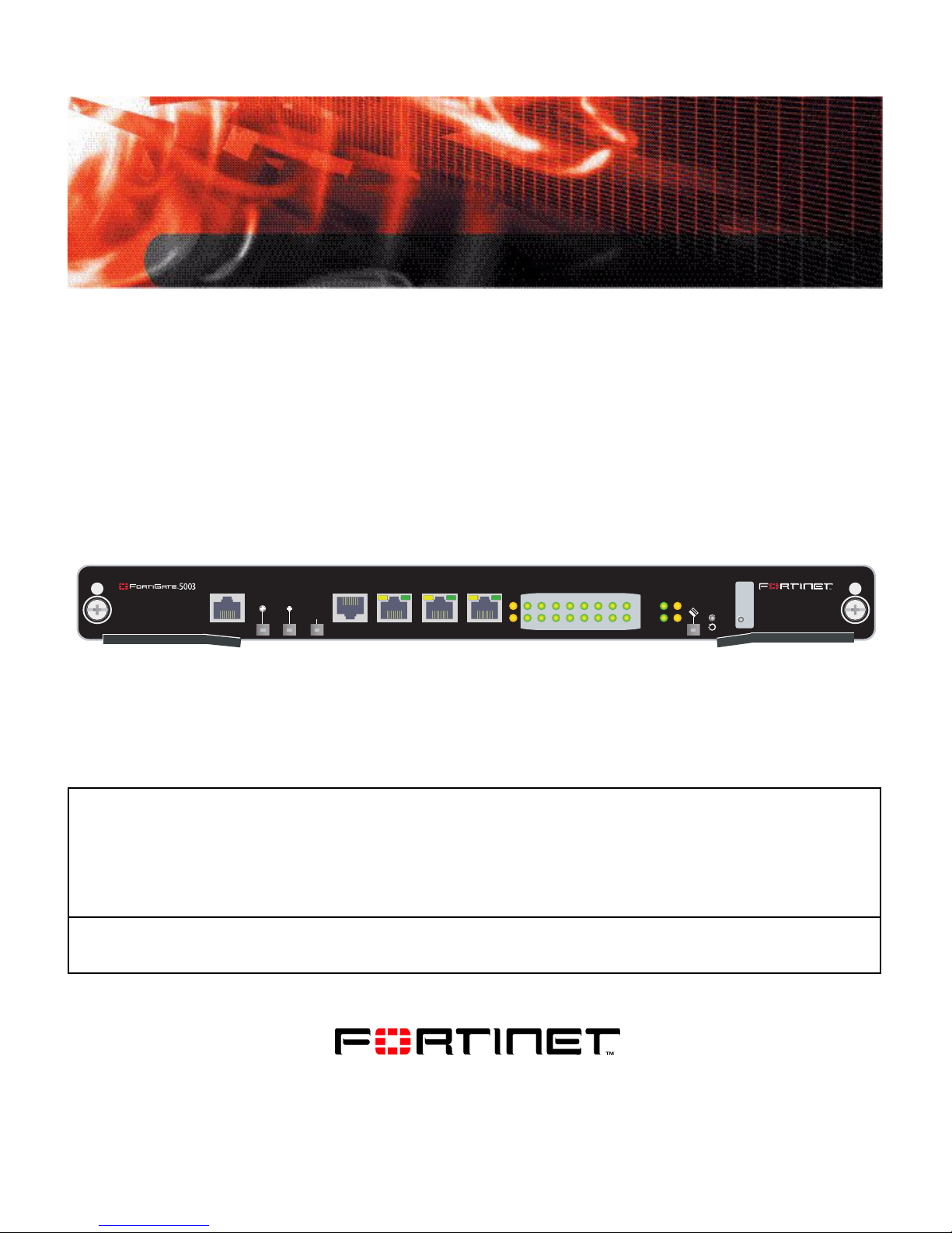
FortiSwitch-5003
O
RS232ZRE0ZRE1
SYSTEM
CONSOLE
ZRE
2
E1
E0
1514
1312
1110
9876543210
OKCLK
INTEXT
FLT
HOT SWAP
ZRE
RESET
FLT
LED MODE
A detailed guide to the features and capabilities of the FortiSwitch-5003 System. This FortiSwitch-5003 System
Guide describes FortiSwitch-5003 hardware feature s, how to install the FortiSwitch-5003 module in a
FortiGate-5000 series chassis, and contains troubleshooting information to help you diagnose and fix problems.
The most recent versions of this and all FortiGate-5000 series documents are available from the FortiGate-5000
page of the Fortinet Technical Documentation web site (http://docs.forticare.com).
Visit http://support.fortinet.com to register your FortiSwitch-5003 system. By registering you can receive product
updates, technical support, and FortiGuard services.
FortiSwitch-5003 System Guide
01-30000-0384-20070201
www.fortinet.com
Page 2

Warnings and cautions
Only trained and qualified personnel should be allowed to install or maintain FortiGate-5000 series
equipment. Read and comply with all warnings, cautions and notices in this document.
CAUTION: Risk of Explosion if Battery is replaced by an Incorrect Type. Dispose of Used Batteries According
!
to the Instructions.
Caution: You should be aware of the following cautions and warnings before installing FortiGate-5000 series
!
hardware
• Turning off all power switches may not turn off all power to the FortiGate-5000 series equipment.
Except where noted, disconnect the FortiGate-5000 series equipment from all power sources,
telecommunications links and networks before installing, or removing FortiGate-5000 series
components, or performing other maintenance tasks. Failure to do this can result in personal injury or
equipment damage. Some circuitry in the Fort iGa te-5000 series equipment may continue to operate
even though all power switches are off.
• An easily accessible disconnect device, such as a circuit breaker, should be incorporated into the data
center wiring that connects power to the FortiGate-5000 series equipment.
• Install FortiGate-5000 series chassis at the lower positions of a rack to avoid making the rack top-heavy
and unstable.
• Do not insert metal objects or tools into open chassis slots.
• Electrostatic discharge (ESD) can damage FortiGate-5000 series equipment. Only perform the
procedures described in this document from an ESD workstation. If no such station is available, you
can provide some ESD protection by wearing an anti-static wrist or ankle strap and attaching it to an
ESD connector or to a metal part of a FortiGate chassis.
• Some FortiGate-5000 series components may overlo ad your supply circuit and imp act your over current
protection and supply wiring. Refer to nameplate ratings to address this concern.
• Make sure all FortiGate-5000 series components have reliable grounding. Fortinet recommends direct
connections to the branch circuit.
• If you install a FortiGate-5000 series component in a closed or multi-unit rack assembly, the operating
ambient temperature of the rack environment may be greater than room ambient. Make sure the
operating ambient temperature does not exceed the manufacturer's maximum rated ambient
temperature.
• Installing FortiGate-5000 series equipment in a rack should be such that the amount of airflow required
for safe operation of the equipment is not compromised.
• This equipment is for installation only in a Restricted Access Location (dedicated equipment room,
service closet or the like), in accordance with the National Electrical Code.
• Per the National Electrical Code, sizing of a Listed circuit breaker or branch circuit fuse and the supply
conductors to the equipment is based on the marked inpu t current rating. A p roduct with a marked input
current rating of 25 A is required to be placed on a 40 A branch circuit. The supply conductors will also
be sized according to the input current rating and also derated for the maximum rated operating
ambient temperature, Tma, of the equipment.
• FortiGate-5000 series equipment shall be installed and connected to an electrical supply source in
accordance with the applicable codes and re gu la tio ns for the location in which it is installed. Particular
attention shall be paid to use of correct wire type and size to comply with the applicable codes and
regulations for the installation / location. Connection of the supply wiring to the terminal block on the
equipment may be accomplished using Listed wire compression lugs, for example, Pressure Terminal
Connector made by Ideal Industries Inc. or equivalent which is suitable for A WG 10. Par ticular attenti on
shall be given to use of the appropriate compre ss ion too l spe cifie d by the compression lug
manufacturer, if one is specified.
FortiSwitch-5003 System Guide
01-30000-0384-20070201
Page 3

Contents
Contents
Warnings and cautions..................................................................................... 2
FortiSwitch-5003 module .................................................. 5
Front panel LEDs and connectors................................................................... 5
LEDs ............................................................................................................. 6
About the ZRE network activity LEDs ........................................................... 7
Connectors.................................................................................................... 8
Base backplane communications.................................................................... 8
Hardware installation....................................................... 11
Inserting a FortiSwitch-5003 module into a chassis .................................... 11
Removing a FortiSwitch-5003 module from a chassis................................. 14
Troubleshooting .............................................................................................. 15
FortiSwitch-5003 does not startup .............................................................. 15
For more information....................................................... 17
Fortinet documentation................................................................................... 17
Fortinet Tools and Documentation CD........................................................ 17
Fortinet Knowledge Center ........................................................................ 17
Comments on Fortinet technical documentation ................................ ........ 17
Customer service and technical support...................................................... 17
Register your Fortinet product....................................................................... 17
FortiSwitch-5003 System Guide
01-30000-0384-20070201 3
Page 4

Contents
FortiSwitch-5003 System Guide
4 01-30000-0384-20070201
Page 5

FortiSwitch-5003 module Front panel LEDs and connectors
FortiSwitch-5003 module
The FortiSwitch-5003 module provides base backplane interface switching for the
FortiGate-5140 chassis and the FortiGate-5050 chassis. You can use this
switching for data communication or HA heartbeat communication between the
base backplane interfaces of FortiGate-5000 series modules installed in slots 3
and up in these chassis. FortiSwitch-5003 modules can be used for base
backplane communication in a single chassis or between multiple chassis.
Install FortiSwitch-5003 modules in chassis slots 1 and 2. A FortiSwitch-5003
module in slot 1 provides communications on base backplane interface 1. A
FortiSwitch-5003 module in slot 2 provides communications on base backplane
interface 2.
If your configuration includes only one FortiSwitch-5003 module you can install it
in slot 1 or slot 2 and configure the FortiGate-5000 modules installed in the
chassis to use the correct base backplane interface.
The FortiSwitch-5003 module includes the following features:
• A total of 16 10/100/1000Base-T gigabit ethernet interfaces:
• 13 backplane 10/100/1000Base-T gigabit interfaces for base backplane
switching between FortiGate-5000 series modules installed in the same
chassis as the FortiSwitch-5003
• Three front panel 10/100/1000Base-T gigabit in terfaces (ZRE0, ZRE1,
ZRE2) for base backplane switching between two or more FortiGate-5000
series chassis
• One 100Base-TX out of band management ethernet interface (ETH0)
• RJ-45 RS-232 serial console connection (CONSOLE)
• Mounting hardware
• LED status indicators
Front panel LEDs and connectors
From the FortiSwitch-5003 font panel you can view the st atus of the modu le LEDs
to verify that the module is functioning normally. You can also connect the
FortiSwitch-5003 module in one chassis to a FortiSwitch-5003 module in another
chassis through the front panel ethernet connect i on s. Th e fron t panel also
includes and out of band management ethernet interface and the RJ-45 console
port for connecting to the FortiSwitch-5003 CLI.
FortiSwitch-5003 System Guide
01-30000-0384-20070201 5
Page 6
Front panel LEDs and connectors FortiSwitch-5003 module
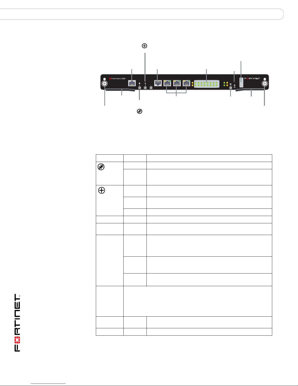
Figure 1: FortiSwitch-5003 front panel
Power LED
Management
100Base-TX
Ethernet
ETH
O
MANAGEMENT
CONSOLE
RJ-45
Serial
RS232ZRE0ZRE1ZRE2
SYSTEM
CONSOLE
ZRE Network
Activity LEDs
(ZRE 0 to 15)
E1
9876543210
1514
1312
1110
E0
LED Mode Switch
Reset
Switch
OKCLK
INTEXT
FLT
HOT SWAP
ZRE
RESET
LED MODE
FLT
LEDs
Mounting
Knot
Extraction
Lever
Out of
Service LED
ZRE0 ZRE1 ZRE2
base backplane interfaces
10/100/1000Base-T
Ethernet
Hot
Swap
LED
Extraction
Lever
Table 1 lists and describes the FortiSwitch-500 3 mo d ule front panel LEDs.
Table 1: FortiSwitch-5003 module front panel LEDs and switches
LED State Description
Off Normal operation.
Red Out of service. The LED turns on if the FortiSwitch-5003
Green The FortiSwitch-5003 module is powered on and operating
Y ellow Caution status. Caution status is indicated by the fault condition
Off The module is not connected to power.
System Off Normal operation.
E0, E1
ZRE 0-15
Yellow or
Green
Green Link/Activity mode: Blinking to indicate network traffic on this
(ZRE
network
activity
LEDs, LED
Yellow Link/Activity mode: The interface is disabled and cannot
Mode
switch
changes
Off Link/Activity mode: No link.
mode)
LED Mode
switch
Change the ZRE network activity LED display mode. Normally the ZRE
network activity LEDs operate in Link/Activity mode. In this mode the LEDs
flash green to indicate a link and to indicate network traffic.
Press this button to switch the ZRE LEDs to Link/Speed mode. In
Link/Speed mode the ZRE LEDs use a solid color to indicate a link. The
color of the LED indicates the speed of the link.
CLK Flashing
Green
OK Green Initialization completed successfully.
module fails. The LED may also flash briefly when the module
is powering on.
normally.
of the CLOCK, OK or INT FLT LEDs.
Link status of out of band management interfaces (no t used ).
interface. Table 2 on page 7 lists the ZRE LEDs and the
interface that each represents.
Link/Speed mode: 100 Mbps connection.
forward packets. (not used)
Link/Speed mode: 1000 Mbps connection.
Link/Speed mode: 10 Mbps connection.
Initialization completed successfully.
Mounting
Knot
FortiSwitch-5003 System Guide
6 01-30000-0384-20070201
Page 7

FortiSwitch-5003 module Front panel LEDs and connectors
Table 1: FortiSwitch-5003 module front panel LEDs and switches (Continued)
LED State Description
EXT FLT Off Normal operation.
Yellow Cannot establish a link to a configured interface or another
INT FLT Off Normal operation.
Yellow Failure of internal tests. Indicates a hardware or software
Hot Swap Blue Indicates the FortiSwitch-5003 module is ready to be hot
Reset
switch
Press and hold Reset for three seconds to restart the FortiSwitch-5003
module.
connection problem external to the FortiSwitch-5003 module.
This LED may indicate issues that do not affect normal
operation.
problem with the FortiSwitch-5003 module.
swapped. During a hot swap, the LED is on. The LED turns off
when the FortiSwitch-5003 module is correctly installed.
About the ZRE network activity LEDs
The ZRE network activity LEDs show links and network activity for the interfaces
and connections listed in Table 2.
Figure 2: FortiSwitch-5003 ZRE network activ i ty LEDs
98
76
54
32
1514
1312
1110
10
ZRE
Table 2: ZRE network activity LEDs FortiSwitch-5003 interfaces and connections
ZRE network
activity LED
0 ZRE0 front panel interface.
1 ZRE1 front panel interface.
2 ZRE2 front panel interface.
3 to 14 Base backplane connection to FortiGate-5000 series modules in chassis
15 Base backplane link. Indicates that the FortiSwitch-5003 module can
Interface or connection
slots 3 to 14.
connect to the base backplane interface.
FortiSwitch-5003 System Guide
01-30000-0384-20070201 7
Page 8

Base backplane communications FortiSwitch-5003 module
Connectors
Table 3 lists and describes the FortiSwitch-5 00 3 fr on t panel conne cto rs .
Table 3: FortiSwitch-5003 connectors
Connector Type Speed Protocol Description
ETH0 RJ-45 100Base-T Ethernet Front panel out of band management
CONSOLE RJ-45 9600 bps RS-232
ZRE0,
ZRE1,
ZRE2
RJ-45 10/100/1000
Base-T
serial
Ethernet Redundant connections to another
interface. A second out of band
management interface, ETH1, connects to
the shelf managers. Neither of the out of
band management interfaces are used.
Serial connection to the command line
interface.
FortiSwitch-5003 module in an different
FortiGate-5140 or FortiGate-5050 chassis.
Use these interfaces for base backpl a ne
interface connections between
FortiGate-5000 series chassis.
Base backplane communications
This section provides a brief introduction to using FortiSwitch-5003 modules for
base backplane communication. See the FortiGate-5000 Base Backplane
Communication Guide for more information about base backplane
communication.
FortiSwitch-5003 modules installed in a FortiGate-5140 or FortiGate-5050 chassis
in slot 1 or slot 2 provide base backplane switching for all of the FortiGate-5000
series modules installed in chassis slots 3 and above. Base backplane switching
can be used for HA heartbeat communication and for data communication
between FortiGate-5000 series modules.
The FortiGate-5000 series modules can all be installed in the same chassis, or
you can use the FortiSwitch-5003 front panel ZRE interfaces for base backplane
communication among multiple FortiGate-5140 and FortiGate-5050 chassis. The
communication can be among a collection of the same chassis (for example,
multiple FortiGate-5050 chassis) or among a mixture of FortiGate-5140 and
FortiGate-5050 chassis. In most cases you would connect the same base
backplane interfaces together, but you can also use the FortiSwitch-5003 front
panel ZRE interfaces for connections between base backplane interface 1 and
base backplane interface 2. Again these connections can be within the same
chassis or among multiple chassis.
A FortiSwitch-5003 module in slot 1 provides communications on base backplane
interface 1. The FortiGate-5001SX and the FortiGate-5001FA2 modules
communicate with base backplane interface 1 using the interface named port9.
The FortiGate-5005FA2 module communicates with base backplane interface 1
using the interface named base1.
A FortiSwitch-5003 module in slot 2 provides communications on base backplane
interface 2. The FortiGate-5001SX and the FortiGate-5001FA2 modules
communicate with base backplane interface 2 using the interface named port10.
The FortiGate-5005FA2 module communicates with base backplane interface 2
using the interface named base2.
FortiSwitch-5003 System Guide
8 01-30000-0384-20070201
Page 9

FortiSwitch-5003 module Base backplane communications
In a single chassis, more than one cluster can use the same base backplane
interface for HA heartbeat communication. To separate heartbeat communication
for multiple clusters on the same base backplane interface, configure a different
HA group name and password for each cluster.
In a single chassis, you can also use the same base backplane interface for data
and HA heartbeat communication. If you are operating multiple clusters and
multiple data paths on the same base backplane interface you may experience
some bandwidth limitations. To increase the amount of bandwidth available you
can add a second FortiSwitch-5003 module and use both backplane interfaces for
HA heartbeat and data communication.
If you have two FortiSwitch-5003 modules and two backplane interfaces available
you can balance the traffic between the base backplan e int er fa ces by how you
configure your FortiGate-5000 module data interfaces and HA heartbeat
interfaces. For example, if you have two busy FortiGate-5001SX clusters you
might configure one cluster to use port9 for HA heartbeat traffic and the other to
use port10. If you have a number of data paths that use the same base backplane
interfaces you can change the configuration to distribute traffic between both base
backplane interfaces.
FortiSwitch-5003 System Guide
01-30000-0384-20070201 9
Page 10

Base backplane communications FortiSwitch-5003 module
FortiSwitch-5003 System Guide
10 01-30000-0384-20070201
Page 11

Hardware installation Inserting a FortiSwitch-5003 module into a chassis
Hardware installation
Before use, the FortiSwitch-5003 module must be correctly inserted into slot 1 or
slot 2 in a FortiGate-5140 or FortiGate-5050 chassis.
This chapter describes:
• Inserting a FortiSwitch-5003 module into a chassis
• Removing a FortiSwitch-5003 module from a chassis
• Troubleshooting
Inserting a FortiSwitch-5003 module into a chassis
The following procedure describes how to correctly use the FortiSwitch-5003
mounting components shown in Figure 3 to insert a FortiSwitch-5003 module into
slot 1 or slot 2 of a FortiGate-5140 or FortiGate-5050 chassis.
The FortiSwitch-5003 module left extraction lever contacts to a hidden power
switch. The module must be fully installed in a chassis slot and this extraction
lever must be closed and locked for the FortiSwitch-500 3 module to receive power
and operate normally. If the FortiSwitch-5003 module is not receiving power, the
Hot Swap LED glows blue and all other LEDs remain off.
It is important to carefully seat the FortiSwitch-5003 module all the way into the
chassis, to not use too much force on the extraction levers, and to make sure that
the extraction levers are properly locke d an d en g ag ed with the hid d en pow er
switch. Only then will the FortiSwitch-5003 module power-on and start up
correctly.
Figure 3: FortiSwitch-5003 module mounting components
Alignment Pin
Mounting
Knot
Closed
Extraction
Lever
Alignment Pin
Mounting
Knot
Extraction
Lever
Open
Switch
Contact
Power
Switch
FortiSwitch-5003 modules are hot swappable. The procedure for inserting the
FortiSwitch-5003 module into a FortiGate-5000 series chassis slot is the same
whether or not the FortiGate-5000 series chassis is powered on or not.
FortiSwitch-5003 System Guide
01-30000-0384-20070201 11
Page 12

Inserting a FortiSwitch-5003 module into a chassis Hardware installation
To insert a FortiSwitch-5003 module into a FortiGate-5000 series chassis
Caution: Do not carry the FortiSwitch-5003 module by holding the extraction levers. When
inserting or removing the FortiSwitch-5003 module from a chassis slot, handle the module
!
by the front panel. The extraction levers are designed for positioning and locking the
FortiSwitch-5003 module into a slot in a chassis only and should not be used for handling
the module. If the extraction levers become bent or damaged the FortiSwitch-5003 module
may not align correctly in the chassis slot and the left extraction lever may not activate the
power switch.
To complete this procedure, you need:
• A FortiSwitch-5003 module
• A FortiGate-5000 series chassis with an empty slot
• An electrostatic discharge (ESD) preventive wrist or ankle strap with
connection cord
Caution: FortiGate-5000 series and FortiSwitch-5000 series modules must be protected
from static discharge and physical shock. Only handle or work with FortiGate-5000 series
!
and FortiSwitch-5000 series modules at a static-free workstation. Always wear a grounded
electrostatic discharge (ESD) preventive wrist or ankle strap when handling FortiGate-5000
series or FortiSwitch-5000 series modules.
1 Attach the ESD wrist or ankle strap to you r wr ist or ankle and to an ESD socket or
to a bare metal surface on the chassis or frame.
2 Open the left and right extraction levers to their fully open positions.
Alignment
Pin
Mounting
Knot
Extraction
Lever
Open
Alignment Pin
Mounting
Knot
Extraction
Lever
Fully Open
3 Insert the FortiSwitch-5003 module into the empty slot in the chassis.
4 Carefully guide the module into the chassis using the rails in the slot.
Insert the module by applying moderate force to the front faceplate (not the
extraction levers) to slide the module into the slot. The module should glide
smoothly into the chassis. If you encounter any resistance while sliding the
module in, the module could be aligned incorrectly. Pull the module back out and
try inserting it again.
5 Slide the module in until the alignment pins are inserted half way into their socket s
in the chassis.
If the chassis is powered on the Hot Swap LED lights up and turns blue.
FortiSwitch-5003 System Guide
12 01-30000-0384-20070201
Page 13

Hardware installation Inserting a FortiSwitch-5003 module into a chassis
6 Turn both extraction levers to their fully-closed positions.
The extraction levers should hook into the sides of the chassis slot. Closing the
extraction levers draws the FortiSwitch-5003 module into place in the chassis slot
and into contact with the chassis backplane. The FortiSwitch-5003 front panel
should be in contact with the chassis front panel.
Alignment
Pin
Mounting
Knot
Extraction
Lever
Close
Alignment
Pin
Mounting
Knot
Extraction
Lever
Fully Closed
If the chassis is powered on, as the module slides into place the Hot Swap LED
starts flashing blue.
7 Fully tighten the left and right mounting knots to lock the For tiSwitch-5003 module
into position in the chassis slot.
.
Mounting
Knot
Tighten
If the chassis is powered on the FortiSwitch-5003 LEDs go th ro ug h a power up
cycle. After a few minutes, if the module is operating correctly the front panel
LEDs are lit as described in Table 4.
Table 4: FortiSwitch-5003 normal operating LEDs
LED State
Off
Green
ZRE 15 Yellow
Other ZRE
May be blinking green if FortiGate-5000 modules are installed.
LEDs
FortiSwitch-5003 System Guide
01-30000-0384-20070201 13
Page 14

Removing a FortiSwitch-5003 module from a chassis Hardware installation
Removing a FortiSwitch-5003 module from a chassis
The following procedure describes how to correctly use the FortiSwitch-5003
mounting components shown in Figure 3 to remove a FortiSwitch-5003 module
from a FortiGate-5000 series chassis slot.
To remove a FortiSwitch-5003 module from a FortiGate-5000 series chassis
FortiSwitch-5003 modules are hot swappable. The procedure for removing the
FortiSwitch-5003 module from a FortiGate-5000 series chassis slot is the same
whether or not the FortiGate-5000 series chassis is powered on or not.
Caution: Do not carry the FortiSwitch-5003 module by holding the extraction levers. When
inserting or removing the FortiSwitch-5003 module from a chassis slot, handle the module
!
by the front panel. The extraction levers are designed for positioning and locking the
FortiSwitch-5003 module into a slot in a chassis only and should not be used for handling
the module. If the extraction levers become bent or damaged the FortiSwitch-5003 module
may not align correctly in the chassis slot and the left extraction lever may not activate the
power switch.
To complete this procedure, you need:
• A FortiGate-5000 series chassis with a FortiSwitch-5003 module installed in it
• An electrostatic discharge (ESD) preventive wrist or ankle strap with
connection cord
1 Attach the ESD wrist or ankle strap to you r wr ist or ankle and to an ESD socket or
to a bare metal surface on the chassis or frame.
2 Disconnect all cables from the FortiSwitch-5003 unit, including all network cables
and console cables.
3 Fully loosen the mounting knots on the lef t and right sides of the FortiSwitch- 5003
front panel.
Mounting
Knot
Loosen
4 Open the left and right extraction levers to their fully open positions.
Opening the extraction levers slides the module a short distance out of the slot,
disconnecting the module from the chassis backplane.
The Hot Swap LED turns blue. All other LEDs turn off.
Alignment
Pin
Mounting
Knot
Extraction
Lever
14 01-30000-0384-20070201
Open
Alignment Pin
Mounting
Knot
Extraction
Lever
Fully Open
FortiSwitch-5003 System Guide
Page 15

Hardware installation Troubleshooting
5 Pull the module about half way out.
All LEDs turn off.
6 Turn both extraction levers to their fully-closed positions.
7 Carefully slide the module completely out of the slot.
Troubleshooting
FortiSwitch-5003 does not startup
Alignment
Pin
Mounting
Knot
Extraction
Lever
Close
Alignment
Pin
Mounting
Knot
Extraction
Lever
Fully Closed
This section describes the following troubleshooting topics:
• FortiSwitch-5003 does not startup
Positioning of FortiSwitch-5003 extraction levers may prevent a FortiSwitch-5003
module for starting up correctly.
All chassis: left extraction lever not contacting power switch
The left extraction lever activates the FortiSwitch-5003 module power switch.
Figure 4: Location of FortiSwitch-5003 power switch
Alignment
Pin
Mounting
Knot
Left Extraction
Lever
Switch
Contact
Power
Switch
If the left extraction lever is damaged or positioned incorrectly the
FortiSwitch-5003 module does not receive power and will not start up. Make sure
the left extraction lever is correctly aligned, fully inserted and locked. Sometimes
you may have to make small adjustments to the extraction lever to achieve
contact with the switch.
FortiSwitch-5003 System Guide
01-30000-0384-20070201 15
Page 16

T roubleshooting Hardware installation
FortiSwitch-5003 System Guide
16 01-30000-0384-20070201
Page 17

For more information Fortinet documentation
For more information
Support for your Fortinet product is availab le as onlin e he lp fr om within the
web-based manager, from the Tools and Documentation CD included with the
product, on the Fortinet Technical Documentation web site, from the Fortinet
Knowledge Center web site, as well as from Fortinet Technical Support.
Fortinet documentation
The most up-to-date publications and previous releases of Fortinet product
documentation are available from the Fortinet Technical Documentation web site
at http://docs.forticare.com. FortiGate-5000 series documentation is located in its
own section of the site at http://docs.forticare.com/fgt5k.html.
Fortinet Tools and Documentation CD
All Fortinet documentation is available from th e Fortinet Tools and Documentation
CD shipped with your Fortinet product. The documents on this CD are current for
your product at shipping time. For the latest versions of all Fortinet documentation
see the Fortinet Technical Documentation web site at http://docs.forticare.com.
Fortinet Knowledge Center
Additional Fortinet technical documentation is available from the Fortinet
Knowledge Center. The knowledge center contains troubleshooting and how-to
articles, FAQs, technical notes, and more. Visit the Fortinet Knowledge Center at
http://kc.forticare.com.
Comments on Fortinet technical documentation
Please send information about any errors or omissions in this document, or any
Fortinet technical documentation, to techdoc@fortinet.com.
Customer service and technical support
Fortinet Technical Support provides services designed to make sure that your
Fortinet systems install quickly, configure easily, and operate reliably in your
network.
Please visit the Fortinet Technical Support web site at http://support.fortinet.com
to learn about the technical support services that Fortinet provides.
Register your Fortinet product
Register your Fortinet product to receive Fortinet customer services such as
product updates and technical support. You must also register your product for
FortiGuard services such as FortiGuard Antivirus and Intrusion Prevention
updates and for FortiGuard Web Filtering and AntiSpam.
Register your product by visiting http://support.fortinet.com and selecting Product
Registration.
To register, enter your contact information and the serial numbers of the Fortinet
products that you or your organization have purchased. You can register multiple
Fortinet products in a single session without re-entering your contact information.
FortiSwitch-5003 System Guide
01-30000-0384-20070201 17
Page 18

© Copyright 2007 Fortinet, Inc. All rights reserved. No part of this publication
including text, examples, diagrams or illustrations may be reproduced,
transmitted, or translated in any form or by any means, electronic, mechanical,
manual, optical or otherwise, for any purpose, without prior written permission of
Fortinet, Inc.
Trademarks
Dynamic Threat Prevention System (DTPS), APSecure, FortiASIC, FortiBIOS,
FortiBridge, FortiClient, FortiGate, FortiGate Unified Threat Management System,
FortiGuard, FortiGuard-Antispam, FortiGuard-Antivirus, FortiGuard-Intrusion,
FortiGuard-Web, FortiLog, FortiAnalyzer, FortiManager, Fortinet, FortiOS,
FortiPartner, FortiProtect, FortiReporter, FortiResponse, FortiShield, FortiVoIP,
and FortiWiFi are trademarks of Fortinet, Inc. in the United States and/or other
countries. The names of actual comp anies and products mentio ned herein may be
the trademarks of their respective owners.
Regulatory compliance
FCC Class A Part 15 CSA/CUS
www.fortinet.com
FortiSwitch-5003 System Guide
01-30000-0384-20070201
 Loading...