

Fortinet FortiSandbox 1000D Quick Start Manual

FortiSandbox 1000D
QuickStart Guide

April 01, 2014
34-110-214953-20140401
Copyright© 2014 Fortinet, Inc. All rights reserved. Fortinet®, FortiGate®,
FortiCare® and FortiGuard®, and certain other marks are registered trademarks
of Fortinet, Inc., and other Fortinet names herein may also be registered and/or
common law trademarks of Fortinet. All other product or company names may be
trademarks of their respective owners. Performance and other metrics contained
herein were attained in internal lab tests under ideal conditions, and actual
performance and other results may vary. Network variables, different network
environments and other conditions may affect performance results. Nothing
herein represents any binding commitment by Fortinet, and Fortinet disclaims
all warranties, whether express or implied, except to the extent Fortinet enters a
binding written contract, signed by Fortinet’s General Counsel, with a purchaser
that expressly warrants that the identified product will perform according to
certain expressly-identified performance metrics and, in such event, only the
specific performance metrics expressly identified in such binding written contract
shall be binding on Fortinet. For absolute clarity, any such warranty will be limited
to performance in the same ideal conditions as in Fortinet’s internal lab tests.
Fortinet disclaims in full any covenants, representations,and guarantees pursuant
hereto, whether express or implied. Fortinet reserves the right to change, modify,
transfer, or otherwise revise this publication without notice, and the most current
version of the publication shall be applicable.

Table of Contents
Package Contents 1
Installation 2
SFP Transceivers 4
Configuring Your Device 6
Technical Specifications 8
LED Specifications 1 9
LED Specifications 2 10
Cautions and Warnings 11
Regulatory Notices 13
Documentation and Links 14
Register Your Product 15
Product License Agreement 16

This page intentionally left blank.
Package Contents
Tools and Documentation
FortiSandbox 1000D
QuickStart Guide
Tools and
Documentation
CD
QuickStart Guide
2 Rack-Mount
Brackets
2 Power Cables Console Cable
4 Rubber
Feet
12 Bracket
Screws
2 Grounding
Screws
Ethernet Cable
Fortinet’s consolidated security solutions provide an integrated set
of core security and network services in a single, easy-to-manage,
high-performance appliance that is capable of supporting a wide
range of deployment scenarios.
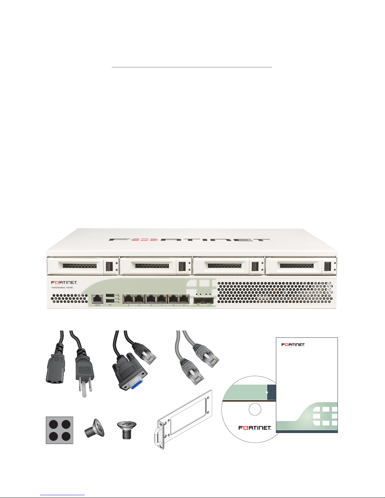
Your box contains the following:
FortiSandbox 1000D Ethernet Cable
QuickStart Guide 4 Rubber Feet
Tools and Documentation CD 2 Grounding Screws
2 Power Cables 12 Bracket Screws
Console Cable 2 Rack-Mount Brackets
Page 1
Note: Accessories may not be exactly as shown.
The FortiSandbox unit can be placed on any flat surface, or mounted in any
standard 19 inch rack unit with the provided rack-mount brackets and screws.
Please read the Cautions and Warnings section prior to installing your device.
Caution: Electrostatic discharge (ESD) can damage your Fortinet equipment.
Caution: Do not place heavy objects on the unit.
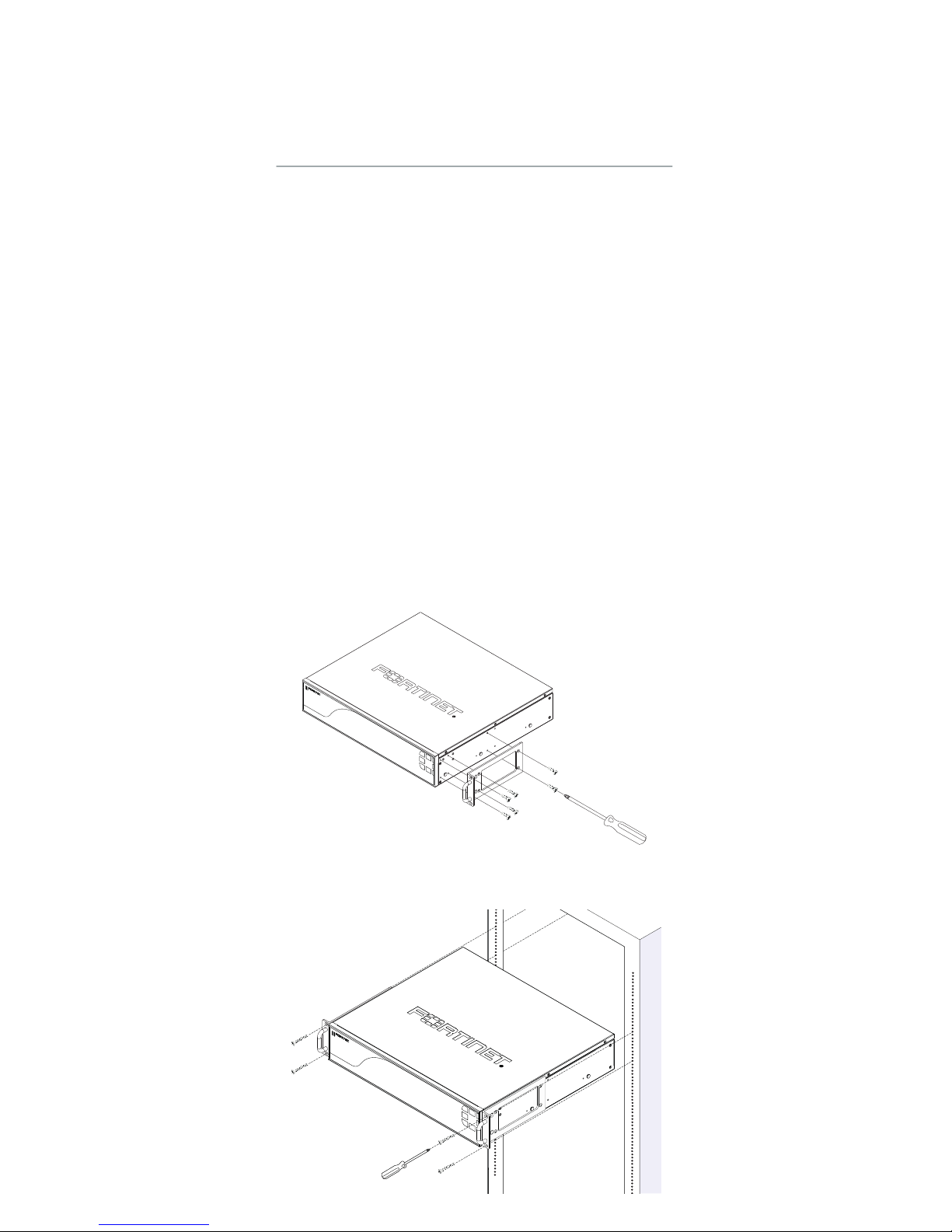
To install the FortiSandbox unit into a rack:
Caution: To avoid personal injury or damage to the unit, it is recommended that
two or more people install the unit into the rack.
1. Ensure that the FortiSandbox unit is placed on a stable surface prior to rack-
mount installation.
2. Attach the provided rack-mount brackets to the sides of the unit using the
provided screws.
a. If you are installing the unit into a four-post rack, attach the rack-mount brackets
with the handles aligned with the front of the unit.
b. If you are installing the unit into a two-post rack, attach the rack-mount brackets
with the handles aligned with the middle of the unit.
Installation
Page 2
3. Position the FortiSandbox unit in the rack. Ensure there is enough room around
the unit to allow for sufficient air flow.
4. Line up the rack-mount bracket holes to the holes on the rack and ensure that the
FortiSandbox unit is level.
5. Finger tighten four rack-mount screws to attach the unit to the rack.
6. Verify that the spacing around the FortiSandbox unit conforms to requirements
and that the unit is level, then tighten the rack-mount screws with an appropriate
screwdriver.
7. Using the provided power cables, plug the cables into the rear of the unit, and
then into a grounded electrical outlet or a separate power source such as an
uninterruptible power supply (UPS) or a power distribution unit (PDU).
Note: If the unit has a redundant power supply, each power cable should be
connected to a different power source. In this way, if one power source fails, the
other may still be operational and the unit will not lose power.
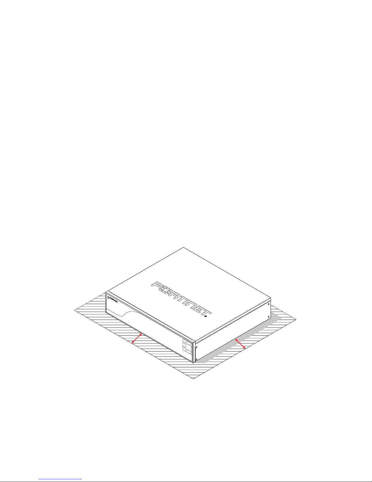
To install the unit on a flat surface:
1. Ensure that the surface onto which the FortiSandbox unit to be installed is clean,
level, and stable and that there is at least 1.5in (3.8cm) of clearance on all sides to
allow for adequate airflow.
2. Attach the provided rubber feet to the bottom of the FortiSandbox unit.
3. Place the unit in the designated location.
4. Verify that the spacing around the FortiSandbox unit conforms to requirements
and that the unit is level.
5. Using the provided power cables, plug the cables into the rear of the unit, and
then into a grounded electrical outlet or a separate power source such as an
uninterruptible power supply (UPS) or a power distribution unit (PDU).
Note: If the unit has a redundant power supply, each power cable should be
connected to a different power source. In this way, if one power source fails, the
other may still be operational and the unit will not lose power.
Page 3
1.5in
1.5in
Caution: SFP transceivers are static sensitive devices. Use an ESD wrist strap or
similar grounding device when handling transceivers.
Caution: Do not install or remove SFP transceivers while fiber-optic cables are still
attached. This can cause damage to the cables, cable connectors, and the optical
interfaces. It may also prevent the transceiver from latching correctly into the socket
connector.
Note: Installing and removing SFP transceivers can shorten their useful life. Do not
install or remove transceivers more than is necessary.
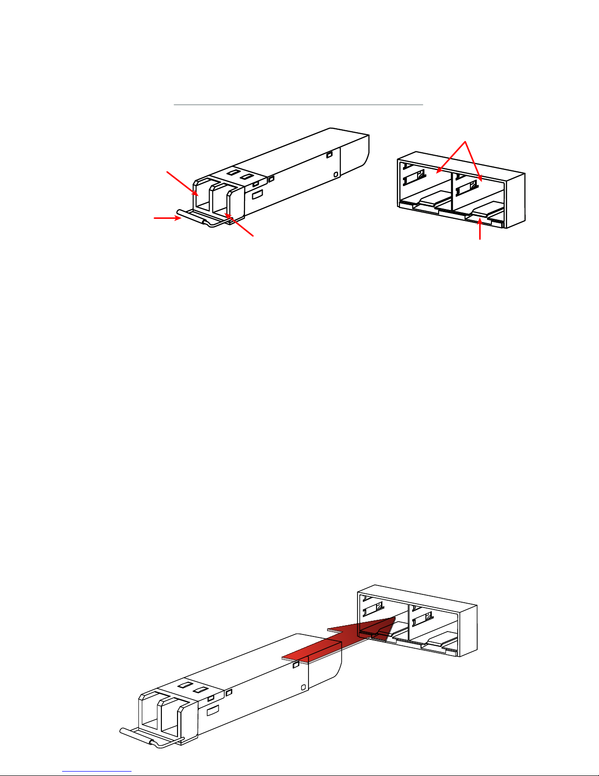
To install the SFP transceivers:
1. Ensure that you are properly grounded.
2. Remove the caps from SFP cage sockets on the front panel of the unit.
3. Position the SFP transceiver in front of the cage socket opening and ensure that
the transceiver is correctly oriented.
When the transceiver is correctly oriented, the extraction lever will be level with
the socket latch.
Note: SFP cage socket orientation may vary. Ensure that the SFP transceiver
module is correctly oriented each time that you are inserting a transceiver.
4. Hold the sides of the SFP transceiver and slide it into the cage socket until it clicks
into place.
SFP Transceivers
Extraction Lever
Transmit
Optical Bore
Receive
Optical Bore
Socket Latch
SFP Cage Sockets
Page 4
 Loading...