

Fortinet FortiRecorder 100D, FortiRecorder 200D, FortiRecorder 400D Administration Manual

FortiRecorder™ 2.4.2
Administration Guide

FortiRecorder 2.4.2 Administration Guide
November 4, 2016
1st Edition
Copyright © 2016 Fortinet, Inc. All rights reserved. Fortinet®, FortiGate®, FortiCare® and
FortiGuard®, and certain other marks are registered trademarks of Fortinet, Inc., and other
Fortinet names herein may also be registered and/or common law trademarks of Fortinet. All
other product or company names may be trademarks of their respective owners. Performance
and other metrics contained herein were attained in internal lab tests under ideal conditions,
and actual performance and other results may vary. Network variables, different network
environments and other conditions may affect performance results. Nothing herein represents
any binding commitment by Fortinet, and Fortinet disclaims all warranties, whether express or
implied, except to the extent Fortinet enters a binding written contract, signed by Fortinet’s
General Counsel, with a purchaser that expressly warrants that the identified product will
perform according to certain expressly-identified performance metrics and, in such event, only
the specific performance metrics expressly identified in such binding written contract shall be
binding on Fortinet. For absolute clarity, any such warranty will be limited to performance in the
same ideal conditions as in Fortinet’s internal lab tests. Fortinet disclaims in full any covenants,
representations, and guarantees pursuant hereto, whether express or implied. Fortinet reserves
the right to change, modify, transfer, or otherwise revise this publication without notice, and the
most current version of the publication shall be applicable.
Technical Documentation http://help.fortinet.com
Knowledge Base http://kb.fortinet.com
Forums https://support.fortinet.com/forum
Customer Service & Support https://support.fortinet.com
Training Services http://training.fortinet.com
FortiGuard Threat Research & Response http://www.fortiguard.com
Document Feedback Email: techdocs@fortinet.com

Table of contents
Key concepts .................................................................................................... 7
FortiRecorder NVR................................................................................................... 7
Camera support ....................................................................................................... 7
Deployment scenarios and camera discovery......................................................... 8
Local camera deployments................................................................................ 8
Same network deployments ........................................................................ 8
Routed network deployments...................................................................... 8
Private network vs office network................................................................ 8
Remote camera deployments............................................................................ 9
Video clips ............................................................................................................... 9
Performance guidelines ........................................................................................... 9
NVR performance .............................................................................................. 9
Number of supported cameras.................................................................... 9
General performance factors ..................................................................... 10
Variable versus constant bit rate................................................................ 10
Bandwidth per camera or live view............................................................ 10
Storage capacity ........................................................................................ 11
Client Performance .......................................................................................... 12
GUI and CLI ........................................................................................................... 13
NVR configuration .......................................................................................... 14
Connecting to FortiRecorder web UI..................................................................... 14
Connecting to FortiRecorder CLI........................................................................... 15
Basic NVR configuration........................................................................................ 17
Setting the “admin” account password ........................................................... 17
Configuring the network settings..................................................................... 18
Configuring the DHCP server .......................................................................... 23
Setting the system time ................................................................................... 26
Configuring schedules ........................................................................................... 28
Setting the sunrise and sunset time................................................................. 29
Advanced/optional NVR configuration .................................................................. 29
Configuring system timeout, ports, and public access ................................... 29
About FortiRecorder logical interfaces ............................................................ 30
VLAN subinterfaces.................................................................................... 30
Redundant interfaces................................................................................. 31
Aggregate interfaces.................................................................................. 31
Loopback interfaces .................................................................................. 31
Configuring FortiRecorder system appearance............................................... 31
Configuring logging ......................................................................................... 31
Alert email ........................................................................................................ 34
Page 3

Camera settings ............................................................................................. 36
Camera configuration workflow............................................................................. 36
Configuring video profiles...................................................................................... 36
Configuring camera profiles................................................................................... 37
Camera groups ...................................................................................................... 39
Camera connection........................................................................................ 40
Camera discovery and DHCP service ................................................................... 40
Connecting FortiRecorder to the cameras ............................................................ 41
Configuring cameras.............................................................................................. 44
User management .......................................................................................... 53
User types.............................................................................................................. 53
User configuration workflow .................................................................................. 53
Configuring access profiles ................................................................................... 54
Configuring user profiles........................................................................................ 54
Configuring user accounts..................................................................................... 54
Configuring LDAP authentication .......................................................................... 60
Configuring RADIUS authentication ...................................................................... 66
Notifications.................................................................................................... 68
Notification configuration workflow ....................................................................... 68
Configuring FortiRecorder to send notification email ............................................ 68
Configuring FortiRecorder to send SMS messages .............................................. 70
Configuring cameras to send notifications ............................................................ 71
Video monitoring ............................................................................................ 73
Watching live video feeds ...................................................................................... 73
Video and image sharing ....................................................................................... 74
Watching recorded video clips .............................................................................. 77
Reviewing motion detection notifications.............................................................. 79
Video management ........................................................................................ 81
Local storage ......................................................................................................... 81
Configuring RAID levels ................................................................................... 81
Recommended HDD models and capacities................................................... 81
Adding a RAID disk .......................................................................................... 82
Replacing a RAID disk ..................................................................................... 82
Replacing all RAID disks .................................................................................. 83
External storage..................................................................................................... 84
System monitoring ......................................................................................... 86
The dashboard....................................................................................................... 86
SNMP traps & queries ........................................................................................... 86
Configuring an SNMP community ................................................................... 88
Configuring SNMP v3 users............................................................................. 90
MIB support ..................................................................................................... 91
Table of contents Page 4 FortiRecorder 2.4.2 Administration Guide

Logging ................................................................................................................. 92
About logs........................................................................................................ 92
Log types ................................................................................................... 92
Log severity levels...................................................................................... 93
Viewing log messages ..................................................................................... 93
Displaying & sorting log columns & rows......................................................... 95
Downloading log messages............................................................................. 96
Deleting log files............................................................................................... 96
Searching logs ................................................................................................. 97
Event Monitor......................................................................................................... 98
Secure connections and certificates............................................................ 99
Supported cipher suites & protocol versions................................................... 99
Replacing the default certificate for the web UI............................................. 100
Generating a certificate signing request .................................................. 103
Uploading & selecting to use a certificate ............................................... 105
Uploading trusted CAs’ certificates ............................................................... 107
Example: Downloading the CA’s certificate from
Microsoft Windows 2003 Server............................................................ 108
Revoking certificates...................................................................................... 109
Revoking certificates by OCSP query...................................................... 109
Updating the firmware ................................................................................. 111
Installing NVR firmware........................................................................................ 111
Installing alternate firmware ........................................................................... 114
Booting from the alternate partition ............................................................... 115
Upgrading/downgrading the camera firmware.................................................... 116
Fine-tuning & best practices ....................................................................... 118
Hardening security............................................................................................... 118
Topology ........................................................................................................ 118
Administrator access ..................................................................................... 119
Operator access............................................................................................. 120
Patches .......................................................................................................... 120
Improving performance........................................................................................ 121
Video performance......................................................................................... 121
System performance...................................................................................... 121
Logging & alert performance ......................................................................... 122
Packet capture performance ......................................................................... 122
Regular backups.................................................................................................. 122
Restoring a previous configuration ................................................................ 124
Troubleshooting ........................................................................................... 125
Solutions by issue type........................................................................................ 125
Video viewing issues...................................................................................... 125
Live feed delay ......................................................................................... 126
Video not being sent to the NVR.............................................................. 126
Snapshot notification issues .......................................................................... 126
Table of contents Page 5 FortiRecorder 2.4.2 Administration Guide

Login issues ................................................................................................... 127
When an administrator account cannot log in from a specific IP ............ 127
Remote authentication query failures ...................................................... 127
Resetting passwords ............................................................................... 127
Connectivity issues ........................................................................................ 127
Checking hardware connections ............................................................. 128
Bringing up network interfaces ................................................................ 128
Examining the ARP table ......................................................................... 129
Checking routing...................................................................................... 129
Facilitating discovery ............................................................................... 133
DHCP issues ............................................................................................ 133
Unauthorized DHCP clients or DHCP pool exhaustion...................... 134
Establishing IP sessions........................................................................... 134
Resolving IP address conflicts................................................................. 136
Packet capture......................................................................................... 137
Resource issues............................................................................................. 142
Data storage issues ....................................................................................... 143
Resetting the configuration.................................................................................. 143
Restoring firmware (“clean install”)...................................................................... 144
Questions and answers ............................................................................... 147
How to connect cameras to FortiRecorder for the first time ............................... 147
Scenario 1: Direct connection........................................................................ 147
Scenario 2: Connection with a third party DHCP server................................ 150
How to use recorded video clips ......................................................................... 151
How to use DIDO terminal connectors on FortiCam MB13 cameras.................. 154
Appendix A: Port numbers........................................................................... 157
Appendix B: Maximum values ..................................................................... 159
Index .............................................................................................................. 161
Table of contents Page 6 FortiRecorder 2.4.2 Administration Guide
Key concepts
This chapter defines basic FortiRecorder concepts and terms.
If you are new to FortiRecorder, or new to digital video surveillance systems, this chapter can
help you to quickly understand how to use your FortiRecorder system.
• FortiRecorder NVR
• Camera support
• Deployment scenarios and camera discovery
• Video clips
• Performance guidelines
FortiRecorder NVR
The FortiRecorder network video recorder (NVR) provides central management for:
• configuring your cameras
• recording your video feeds
• viewing recordings and live video feeds
Camera support
The FortiRecorder NVR supports FortiCam series cameras from Fortinet and third-party
ONVIF-compliant cameras, although some of the third-party camera features may not be fully
supported. Therefore, you may want to configure those features through its built-in camera web
interface.
By default, every FortiRecorder or FortiRecorder-VM appliance supports one third-party
camera. If you want to connect more than one, you must purchase licenses from Fortinet. For
more information, please contact Fortinet or the resellers.
Page 7
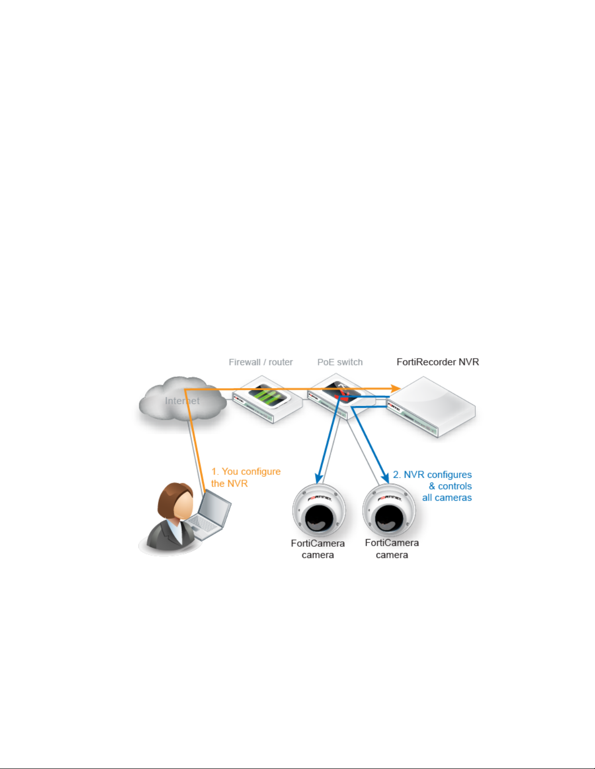
Deployment scenarios and camera discovery
Cameras are deployed in two basic scenarios: local to the NVR and remote to the NVR.
FortiCamera deployments can combine both scenarios.
Local camera deployments
Local cameras deployments have two specific scenarios:
• Cameras are installed on the same network as the NVR.
• Cameras are installed on a local network, but there are one or more routers between the
NVR and the cameras.
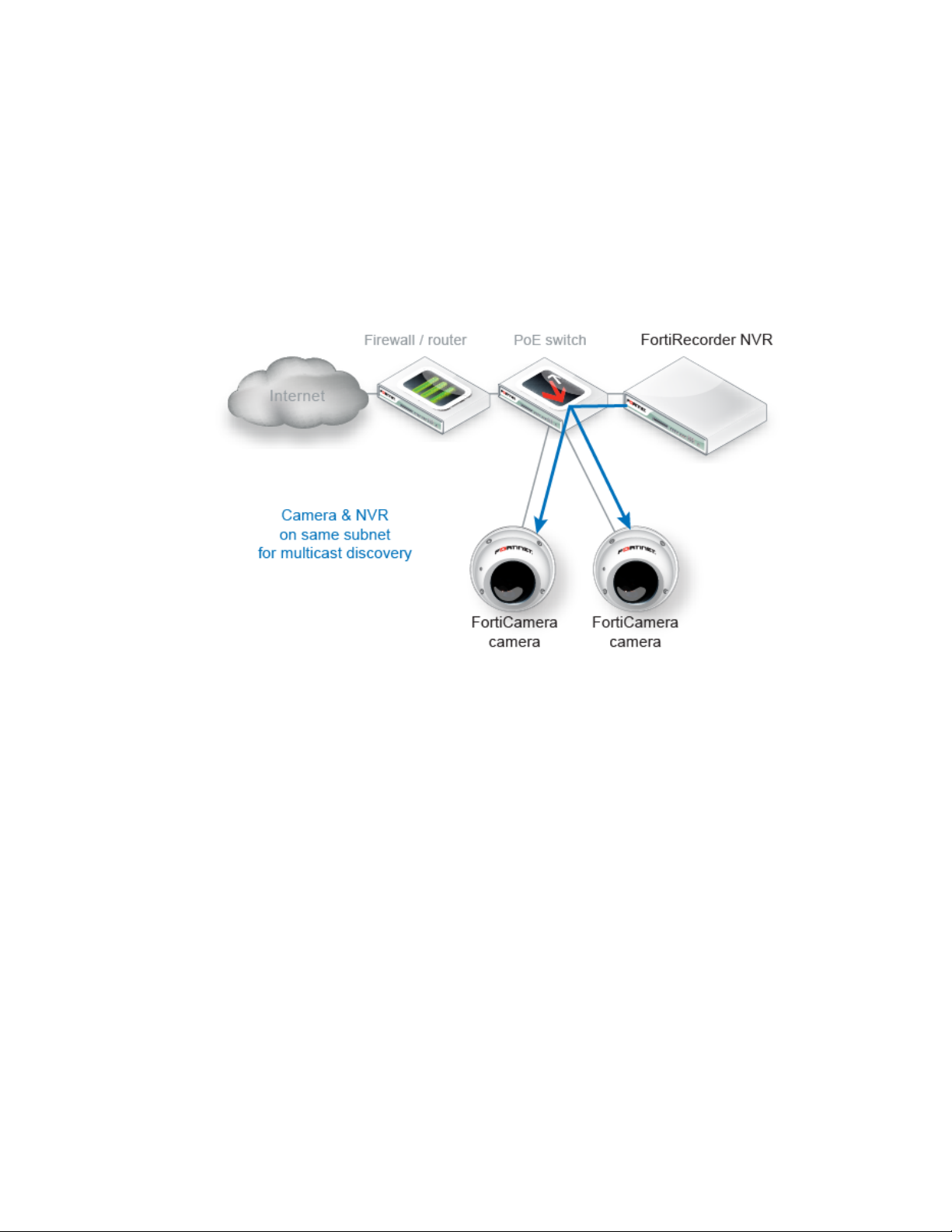
Same network deployments
Installing the cameras on the same subnet as the NVR is the easiest deployment scenario since
the NVR can automatically discover the cameras.
Routed network deployments
If there are routers between the cameras and the NVR, the routers must be configured to allow
mDNS multicast packets between the camera network and the NVR network in order for the
NVR to automatically discover the cameras. Once the cameras are discovered, you can leave
the address mode as DHCP or change it to static.
If the routers are not configured to pass the mDNS packets, the cameras can be configured
manually by selecting the static address mode on the camera configuration page.
Private network vs office network
You can install the NVR and cameras on your existing network, which saves your efforts and
costs. You can also install the system on a dedicated private network only reachable by the
Key concepts Page 8 FortiRecorder 2.4.2 Administration Guide

Remote camera deployments
Video clips
NVR. Although this involves installing a new network and thus increasing the costs, there are
some advantages of using a private network:
• the video streams are protected.
• the cameras are protected because they cannot be reached from outside the network.
• easier to determine bandwidth requirements.
• better quality of service since bandwidth is known.
See also
• Facilitating discovery
Remote camera deployments refer to scenarios where there is a firewall between the NVR and
the cameras – i.e. camera discovery will not work and the cameras will likely have virtual IP
addresses on the firewall. The cameras are configured by selecting the VIP address mode on
the camera configuration page.
You can use FortiRecorder to:
• Manually record activities
• Continuously record activities by schedules
• Record sudden activities only (motion detection)
• Record audio activities (if the camera supports audio detection)
• Record on triggers from digital input (if the camera support DIDO)
• View live video
Motion detection will record a video clip up to about 40 seconds long each time the camera’s
sensor detects movement. In contrast, continuous video records for the entire duration of the
schedule, regardless of movement.
Performance guidelines
There are two components to consider when looking at FortiRecorder performance – the NVR
(FortiRecorder) and the Client computer with FortiRecorder Central or a browser. Overall
FortiRecorder performance is a combination of the video input (video compression, image
quality level, complexity of the scene, video resolution, frame rate per second, number of
cameras) and the video output (to the clients for live views and playback). The performance
bottleneck in a FortiCamera deployment will likely be the network bandwidth to and from
FortiRecorder and the CPU performance of the computer running the FortiRecorder Central or
browser client, which must decode and render the video streams from the NVR. Displaying
multiple video streams on the client is very CPU intensive.
NVR performance
Number of supported cameras
The FortiRecorder-100D can support 16 cameras, 200D and 400D can support up to 64
cameras depending on the camera configuration. VM version of FortiRecorder depends on the
hardware performance.
Key concepts Page 9 FortiRecorder 2.4.2 Administration Guide

General performance factors
The following factors affect the input side of performance:
• Total number of video streams from the cameras (i.e. not just the number of cameras)
• The video recording types (motion only or continuous) per camera
• The video stream parameters per camera – i.e. video compression (constant or variable bit
rate mode), image quality level, complexity of the scene, video resolution and frame rate per
second.
The following factors affect the output side of performance:
• Number of administrator/operator/viewer sessions
• Peak number of simultaneous administrator/operator/viewer live views
• The video stream parameters per camera live view – i.e. video compression (constant or
variable bit rate mode), image quality level, complexity of the scene, video resolution and
frame rate per second.
Variable versus constant bit rate
The variable bit rate mode means the bandwidth used by the camera will vary according to what
the camera is seeing and the video profile settings. The video profile settings for the variable bit
rate mode are resolution, frame rate and image quality. High resolution creates more data than
medium or low resolution (see following sections for more detail). The degree of motion present
in a video stream also affects the amount of data created.
The constant bit rate mode means the bandwidth used by the camera will stay relatively
constant regardless of what the camera is seeing. The constant bit rate mode is therefore more
predictable in deployments where bandwidth and/or storage capacities are important
considerations. The video profile settings for the constant bit rate mode are resolution, frame
rate and bit rate. The bandwidth used by the stream is dictated by the bit rate setting.
In general, using the variable bit rate mode results in relatively consistent video quality but
fluctuating bandwidth and using the constant bit rate mode results in varying video quality but
predictable bandwidth. Choosing a high bandwidth constant bit rate mode avoids the video
quality drop e.g. during high motion, but may use some unnecessary bandwidth during times of
no activity.
However, in most cases the difference in video quality between the variable and constant bit
modes is negligible (assuming the same resolution and frame rates) and the constant bit rate
mode produces more reliable output from the cameras.
Bandwidth per camera or live view
Variable bit rate
Depending on resolution, frame rate and video quality a camera using H.264 compression may
generate the following bit rates:
• 352 x 240 @ 30 FPS, high quality = 0.4 Mbps
• 720 x 576 @ 30 FPS, high quality = 1 Mbps
• 1280 x 720 @ 30 FPS, high quality = 2 Mbps
• 1920 x 1080 @ 30 FPS, high quality = 4 Mbps
• 1920 x 1080 @ 30 FPS, medium quality = 2.8 Mbps
• 1920 x 1080 @ 30 FPS, low quality = 2 Mbps
• 1920 x 1080 @ 10 FPS, high quality = 2.4 Mbps
• 1920 x 1080 @ 10 FPS, low quality = 1.2 Mbps
Key concepts Page 10 FortiRecorder 2.4.2 Administration Guide

Table 1: Bitrate table (H.264 estimate) in Mbps with high quality image (x0.7 = standard quality)
Frames/s 1 6 10 15 30
CIF
0.16 0.2 0.24 0.3 0.4
(352x240)
D1 0.4M
0.4 0.5 0.6 0.75 1
(720x576)
720p 1M 0.8 1 1.2 1.5 2
SXGA 1.3M
1 1.25 1.5 1.9 2.5
(1280x1024)
HD 2M
1.6 2 2.4 3 4
(1920x1080)
3M 2 2.5 3 3.75 5
5M 3.2 4 4.8 6 8
Please note that these are estimates providing a high quality image under most conditions. If
the scene is less complex (indoors with little detail and not much motion) or the camera has very
little noise (daylight, good DNR) the bit rate can be lowered further. Generally do not use less
than half of the indicated values.
If video compression is set to lower quality or capped at a defined max bandwidth, the bit rate
can be significantly lower at the cost of lower image quality. DNR can further reduce bandwidth,
especially for grainy night images, but shows less detail during motion.
Storage capacity
We will use FortiRecorder 100D, 200D and 400D configuration with different camera parameters
to demonstrate the video retention period.
FortiRecorder 100D has a built in 1 TB hard drive and it can connect up to 16 cameras. We
configure 16 cameras with 1280 x 720 resolution using 30 FPS with high quality image in
continuous recording. Each camera will generate an estimated bandwidth of 2 Mbps. Referring
to the FortiRecorder Capacity calculator spreadsheet below, 100D can store approximately 3.2
days of video footage.
Table 2: Capacity Calculator
Bit rate
(Mbps)
Input 2 1 16 100 30
Resolve each for all other inputs as specified
Result 0.2 9.4 1.7 11 3.2
FortiRecorder 200D has 3 TB HD capacity. With the same configuration it can record 16
cameras for 10 days.
HD
Capacity
(TB)
Cameras
(#)
Usage
(%)
Time
(days)
FortiRecorder 400D has 6 TB HD capacity. With the same configuration it can record 16
cameras for 19 days.
Key concepts Page 11 FortiRecorder 2.4.2 Administration Guide

The above examples use the same configuration for 16 cameras with different hard drive
capacity per FortiRecorder model. The table below shows the number of days that one camera
can be stored in different configurations.
Table 3: Video retention period in days for one camera
The same resolution and frame rate with different video quality
1920x1080@15 FPS
high quality video = 3
Mbps
1920x1080@15 FPS
medium quality video
= 2.1 Mbps
The same resolution and video quality with different frame rate
2048x1536@10 FPS
high quality video = 3
Mbps
2048x1536@30 FPS
high quality video = 5
Mbps
FortiRecorder
100D with 1 TB
HD
34 102 645 204
49 145 921 291
34 102 645 204
20 61 387 122
FortiRecorder
200D with 3 TB
HD
FortiRecorder
200D with 3 TB
HD plus 16 TB
remote
storage
FortiRicorder
400D with 6
TB HD
Use the following guideline for a quick bandwidth consumption calculation:
• 1 TB HD can store 1 camera configured to consume 1Mbps for approximately 100 days.
Therefore:
• 1 TB HD can store 1 camera configured to consume 2 Mbps for approximately 50 days.
• 6 TB HD can store 10 cameras configured to consume 2 Mbps each for approximately 30
days.
For more information about bandwidth consumption calculation, see the FortiCamera
Bandwidth Calculator User Guide on
http://docs.fortinet.com/d/fortirecorder-forticamera-bandwidth-calculator-user-guide.
In practice Fortinet suggests to use the numbers provided in the bandwidth calculator as a
starting point and then adjust them after installation to achieve the desired balance between
quality and bandwidth.
Client Performance
If you need to display 8 or more camera live views, you may need to configure the second
camera stream so that viewing is done at a lower frame rate or resolution, depending on how
powerful the client PC is. RAM is less important than CPU for rendering video.
Video playback is very CPU intensive. If you are experiencing choppy video playback and
cameras “freezing” during playback, you likely have a client performance problem. Use the
diagnostic tools available on your client OS and look at the CPU usage when you are
experiencing video problems. If possible, keep the CPU usage below 50%.
Key concepts Page 12 FortiRecorder 2.4.2 Administration Guide

GUI and CLI
To optimize client performance, use the video and camera profiles to define and assign a
second video stream for each camera. To increase the number of live views the client computer
can display, or to reduce the CPU requirement for a given number of live views, reduce the
resolution, quality and/or frames per second of the second video streams.
Ten FPS is a good general setting for live views, which provides a reasonable frame rate for the
live views, but significantly reduces the load on the client (compared to 30 FPS which is more
ideal for higher traffic area surveillance).
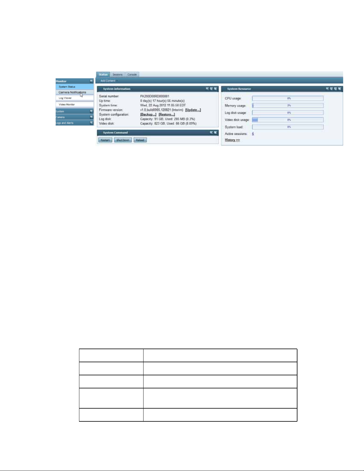
This document only describes how to use the web UI. If you are familiar with the command line
interface (CLI), go to Monitor > System Status > Console to use the CLI commands.
Key concepts Page 13 FortiRecorder 2.4.2 Administration Guide

NVR configuration
To be able to configure the FortiRecorder NVR appliance, you must connect to its management
web UI or CLI console. This document mainly describes the web UI usage.
Connecting to FortiRecorder web UI
You can connect to the web UI using its default settings. (By default, HTTPS access to the
web UI is enabled.)
Table 4: Default settings for connecting to the web UI
Network Interface port1
URL https://192.168.1.99/
Administrator
Account
Password
Requirements
• a computer with an RJ-45 Ethernet network port
• a crossover Ethernet cable
• a web browser. For supported web browsers, see the release notes.
• If you are running FortiRecorder version 2.3 and older firmware, Apple QuickTime 7.1 or
greater plug-in is required for video display. Note that starting from QuickTime 7.7.9,
QuickTime typical install does not install the web plugin by default. You have to use
custom install and select the web plugin.
Starting from FortiRecorder version 2.4, HTML5 is supported. On most platforms, QuickTime
plugin is not required anymore. For details, see the FortiRecorder version 2.4 release notes.
To connect to the web UI
1. On your management computer, configure the Ethernet port with the static IP address
192.168.1.2 with a netmask of 255.255.255.0.
2. Using the Ethernet cable, connect your computer’s Ethernet port to the FortiRecorder
appliance’s port1.
3. Start your browser and enter the URL:
https://192.168.1.99/
(Remember to include the “s” in https://.)
Your browser connects the appliance.
admin
Page 14
4. In the Name field of the login page, type admin, then click Login. (In its default state, there is
no password for this account.)
Login credentials entered are encrypted before they are sent to the FortiRecorder appliance.
If your login is successful, the web UI appears.
See also
• Connectivity issues
• Login issues
Connecting to FortiRecorder CLI
For initial configuration, you can access the CLI from your management computer using either
of these two ways:
• a local serial console connection
• an SSH connection, either local or through the network
To connect to the CLI using a local serial console connection, you must have:
• a computer with a serial communications (COM) port
• the RJ-45-to-DB-9 serial or null modem cable included in your FortiRecorder package
• terminal emulation software, such as HyperTerminal for Microsoft Windows
To connect to the CLI using an SSH connection, you must have:
• a computer with an Ethernet port
• a crossover Ethernet cable
• an SSH client, such as PuTTY
Table 5: Default settings for connecting to the CLI by SSH
Network Interface port1
IP Address 192.168.1.99
SSH Port Number 22
Administrator
Account
Password (none)
NVR configuration Page 15 FortiRecorder 2.4.2 Administration Guide
admin

To connect to the CLI using a local serial console connection
The following procedure uses Microsoft HyperTerminal. Steps may vary with other terminal
emulators.
1. Using the RJ-45-to-DB-9 or null modem cable, connect your computer’s serial
communications (COM) port to the FortiRecorder unit’s console port.
2. Verify that the FortiRecorder unit is powered on.
3. On your management computer, start HyperTerminal.
4. On Connection Description, enter a Name for the connection, and select OK.
5. On Connect To, from Connect using, select the communications (COM) port where you
connected the FortiRecorder unit.
6. Select OK.
7. Select the following Port settings and select OK.
Bits per second 9600
Data bits 8
Parity None
Stop bits 1
Flow control None
8. Press Enter.
The terminal emulator connects to the CLI, and the CLI displays a login prompt.
9. Type admin and press Enter twice. (In its default state, there is no password for this
account.)
To connect to the CLI using an SSH connection
The following procedure uses PuTTY. Steps may vary with other SSH clients.
1. On your management computer, configure the Ethernet port with the static IP address
192.168.1.2 with a netmask of 255.255.255.0.
2. Using the Ethernet cable, connect your computer’s Ethernet port to the FortiRecorder unit’s
port1.
3. Verify that the FortiRecorder unit is powered on.
4. On your management computer, start your SSH client.
5. In Host Name (or IP Address), type 192.168.1.99.
6. In Port, type 22.
7. From Connection type, select SSH.
8. Select Open.
The SSH client connects to the FortiRecorder unit.
The SSH client may display a warning if this is the first time you are connecting to the
FortiRecorder unit and its SSH key is not yet recognized by your SSH client, or if you have
NVR configuration Page 16 FortiRecorder 2.4.2 Administration Guide

previously connected to the FortiRecorder unit but it used a different IP address or SSH key.
If your management computer is directly connected to the FortiRecorder unit with no
network hosts between them, this is normal.
9. Click Yes to verify the fingerprint and accept the FortiRecorder unit’s SSH key. You will not
be able to log in until you have accepted the key.
The CLI displays a login prompt.
10.Type admin and press Enter. (In its default state, there is no password for this account.)
Basic NVR configuration
Either to integrate the FortiRecorder NVR into your existing network or to set it up in its
dedicated, private network, you must configure the following settings to have the appliance up
and running:
• Setting the “admin” account password
• Configuring the network settings
• Configuring the DHCP server
• Setting the system time
Setting the “admin” account password
The default administrator account, named admin, initially has no password.
Unlike other administrator accounts, the admin administrator account exists by default and
cannot be deleted. This administrator account always has full permission to view and change all
FortiRecorder configuration options, including viewing and changing all other administrator
accounts. Its name and permissions cannot be changed.
For security reasons, you must set a password for the admin account after you log on to
FortiRecorder. Set a strong password for the admin administrator account, and change the
password regularly.
To change the admin administrator password
1. Log in to the admin administrator account.
2. Go to System > Administrator > Administrator.
3. Change the password and log out.
The new password takes effect the next time that administrator account logs in.
See also
• Login issues
NVR configuration Page 17 FortiRecorder 2.4.2 Administration Guide

Configuring the network settings
When shipped, each of the FortiRecorder appliance’s physical network adapter ports has a
default IP address and netmask. If these IP addresses and netmasks are not compatible with
the design of your unique network, you must configure them.
Table 6: Default IP addresses and netmasks
Network Interface* IP Address Netmask
port1 192.168.1.99 255.255.255.0
port2 192.168.2.99 255.255.255.0
port3 192.168.3.99 255.255.255.0
port4 192.168.4.99 255.255.255.0
* The number of network interfaces may vary by model.
To connect to the CLI and web UI, you should configure the following FortiRecorder network
settings:
• Interface: you Two configure at least one network interface on your FortiRecorder
appliance (usually port1) with an IP address and netmask so that it can receive your
connections.
• Static route: Depending on your network, you also usually must configure a static route so
that the FortiRecorder can connect to the Internet, your computer, and FortiCam cameras.
• DNS server: FortiRecorder appliances require connectivity to DNS servers for DNS lookups.
The appliance will query the DNS servers whenever it needs to resolve a domain name into
an IP address, such as for NTP servers defined by their domain names.
To configure a network interface’s IP address
1. Log in to the admin administrator account.
2. Go to System > Network > Interface.
3. Double-click the row to select the physical network interface that you want to modify.
4. If you want to manually assign an IP address and subnet mask to this network interface,
select Manual and then provide the IP address and netmask in IP/Netmask. IPv4 and IPv6
subnet masks should be provided in CIDR format, e.g. /24 instead of 255.255.255.0. The
IP address must be on the same subnet as the network to which the interface connects. Two
network interfaces cannot have IP addresses on the same subnet.
Otherwise, select DHCP and enable Connect to server to retrieve a DHCP lease when you
save this configuration. If you want the FortiRecorder appliance to also retrieve DNS and
default route (“gateway”) settings, also enable Retrieve default gateway and DNS from
server.
If you use DHCP on an interface and there are cameras connected to the interface, you must
make sure the IP address will ne change on that interface because the cameras need to
communicate with the NVR and thus need to be aware of the IP address of the NVR.
NVR configuration Page 18 FortiRecorder 2.4.2 Administration Guide

Retrieve default gateway and DNS from server will overwrite the existing DNS and default route,
if any.
5. Configure these settings:
Setting name Description
Discover cameras
on this port
Enable to send multicast camera discovery traffic from this network
interface. For more information, see “Connecting FortiRecorder to the
cameras” on page 41.
Access Enable the types of administrative access that you want to permit to
this interface.
Caution: Enable administrative access only on network interfaces
connected to trusted private networks or directly to your management
computer. If possible, enable only secure administrative access
protocols such as HTTPS or SSH. Failure to restrict administrative
access could compromise the security of your FortiRecorder
appliance.
HTTPS Enable to allow secure HTTPS connections to the web UI through this
network interface. To configure the listening port number, see
“Configuring system timeout, ports, and public access”. To upload a
certificate, see “Replacing the default certificate for the web UI”.
PING Enable to allow:
• ICMP type 8 (ECHO_REQUEST)
• UDP ports 33434 to 33534
for ping and traceroute to be received on this network interface.
When it receives an ECHO_REQUEST, FortiRecorder will reply with
ICMP type 0 (ECHO_RESPONSE).
Note: Disabling PING only prevents FortiRecorder from receiving
ICMP type 8 (ECHO_REQUEST) and traceroute-related UDP.
It does not disable FortiRecorder CLI commands such as execute
ping or execute traceroute that send such traffic.
HTTP Enable to allow HTTP connections to the web UI through this network
interface. To configure the listening port number, see “Configuring
system timeout, ports, and public access”.
Caution: HTTP connections are not secure, and can be intercepted by
a third party. If possible, enable this option only for network interfaces
connected to a trusted private network, or directly to your
management computer. Failure to restrict administrative access
through this protocol could compromise the security of your
FortiRecorder appliance.
SSH Enable to allow SSH connections to the CLI through this network
interface.
NVR configuration Page 19 FortiRecorder 2.4.2 Administration Guide

Setting name Description
SNMP Enable to allow SNMP queries to this network interface, if queries have
been configured and the sender is a configured SNMP manager. To
configure the listening port number and configure queries and traps,
see “SNMP traps & queries”.
TELNET Enable to allow Telnet connections to the CLI through this network
interface.
Caution: Telnet connections are not secure, and can be intercepted
by a third party. If possible, enable this option only for network
interfaces connected to a trusted private network, or directly to your
management computer. Failure to restrict administrative access
through this protocol could compromise the security of your
FortiRecorder appliance.
FRC-
Enable to allow access from FortiRecorder Central.
Central
MTU Enable to change the maximum transmission unit (MTU) value, then
enter the maximum packet or Ethernet frame size in bytes.
If network devices between the FortiRecorder unit and its traffic
destinations require smaller or larger units of traffic, packets may
require additional processing at each node in the network to fragment
or defragment the units, resulting in reduced network performance.
Adjusting the MTU to match your network can improve network
performance.
The default value is 1500 bytes. The MTU size must be between 576
and 1500 bytes. Change this if you need a lower value. For example,
RFC 2516 prescribes a value of 1492 for PPPoE.
Administrative
status
Select either:
• Up — Enable (that is, bring up) the network interface so that it can
send and receive traffic.
• Down — Disable (that is, bring down) the network interface so that
it cannot send or receive traffic.
6. Click OK.
If you were connected to the web UI through this network interface, you are now
disconnected from it.
7. To access the web UI again, in your web browser, modify the URL to match the new IP
address of the network interface. For example, if you configured the network interface with
the IP address 10.10.10.5, you would browse to: https://10.10.10.5
If the new IP address is on a different subnet than the previous IP address, and your
computer is directly connected to the FortiRecorder appliance, you may also need to modify
the IP address and subnet of your computer to match the FortiRecorder appliance’s new IP
address.
NVR configuration Page 20 FortiRecorder 2.4.2 Administration Guide

To add a static route
If you used DHCP and Retrieve default gateway and DNS from server when configuring your
network interfaces, skip this step — the default route was configured automatically.
1. Log in to the admin administrator account.
Other accounts may not have permissions necessary to change this setting.
2. Go to System > Network > Routing.
3. Click New.
4. Configure these settings:
Setting name Description
Destination
IP/netmask
Type the destination IP address and network mask of packets that will
be subject to this static route, separated by a slash ( / ).
The value 0.0.0.0/0 results in a default route, which matches all
packets.
Gateway Type the IP address of the next-hop router where the FortiRecorder
appliance will forward packets subject to this static route. This router
must know how to route packets to the destination IP addresses that
you have specified in Destination IP/netmask, or forward packets to
another router with this information.
For a direct Internet connection, this will be the router that forwards
traffic towards the Internet, and could belong to your ISP.
Note: The gateway IP address must be in the same subnet as a
network interface’s IP address.
5. Click OK.
The FortiRecorder appliance should now be reachable to connections with networks
indicated by the mask. When you add a static route through the web UI, the FortiRecorder
appliance evaluates the route to determine if it represents a different route compared to any
other route already present in the list of static routes. If no route having the same destination
exists in the list of static routes, the FortiRecorder appliance adds the static route, using the
next unassigned route index number.
For small networks with only a few devices, often you will only need to configure one route: a
default route that forwards packets to your router that is the gateway to the Internet.
If you have redundant gateway routers (e.g. dual Internet/ISP links), or a larger network with
multiple routers (e.g. each of which should receive packets destined for a different subset of IP
addresses), you may need to configure multiple static routes.
NVR configuration Page 21 FortiRecorder 2.4.2 Administration Guide

6. To verify connectivity, from a computer on the route’s network destination, attempt to ping
one of FortiRecorder’s network interfaces that should be reachable from that location.
If the connectivity test fails, you can use the CLI commands:
execute ping <destination_ipv4>
to determine if a complete route exists from the FortiRecorder to the host, and
execute traceroute <destination_ipv4>
to determine the point of connectivity failure.
Also enable PING on the FortiRecorder’s network interface, then use the equivalent
tracert or traceroute command on the computer (depending on its operating system)
to test routability for traffic traveling in the opposite direction: from the host to the
FortiRecorder.
• If these tests fail, or if you do not want to enable PING, first examine the static route
configuration on both the host and FortiRecorder.
To display the cached routing table, enter the CLI command:
diagnose netlink rtcache list
You may also need to verify that the physical cabling is reliable and not loose or broken,
that there are no IP address or MAC address conflicts or blacklisting, and otherwise rule
out problems at the physical, network, and transport layer.
• If these tests succeed, a route exists, but you cannot connect using HTTP or HTTPS, an
application-layer problem is preventing connectivity.
Verify that you have enabled HTTPS and/or HTTP on the network interface. Also examine
routers and firewalls between the host and the FortiRecorder appliance to verify that they
permit HTTP and/or HTTPS connectivity between them. Finally, you can also use the CLI
command:
diagnose system top 5 30
to verify that the daemons for the web UI and CLI, such as sshd, newcli, and httpd are
running and not overburdened.
To configure DNS settings
If you will use the settings DHCP and Retrieve default gateway and DNS from server when you
configure your network interfaces, skip this — DNS is configured automatically.
1. Log in to the admin administrator account.
Other accounts may not have permissions necessary to change this setting.
2. Go to System > Network > DNS and enter the IP addresses of a primary and secondary DNS
server. Your Internet service provider (ISP) may supply IP addresses of DNS servers, or you
may want to use the IP addresses of your own DNS servers.
Incorrect DNS settings or unreliable DNS connectivity can cause issues with other features,
including the NTP system time. For improved performance, use DNS servers on your local
network.
3. Click Apply.
NVR configuration Page 22 FortiRecorder 2.4.2 Administration Guide

4. To verify your DNS settings, in the CLI, enter the following commands:
execute traceroute www.fortinet.com
DNS tests may not succeed if you have not yet completed “To add a static route”.
If the DNS query for the domain name succeeds, you should see results that indicate that
the host name resolved into an IP address, and the route from FortiRecorder to that IP
address:
traceroute to www.fortinet.com (192.0.43.10), 30 hops max, 60 byte
packets
1 172.20.130.2 (172.20.130.2) 0.426 ms 0.238 ms 0.374 ms
2 static-209-87-254-221.storm.ca (209.87.254.221) 2.223 ms 2.491
ms 2.552 ms
3 core-g0-0-1105.storm.ca (209.87.239.161) 3.079 ms 3.334 ms
3.357 ms
...
16 43-10.any.icann.org (192.0.43.10) 57.243 ms 57.146 ms 57.001
ms
If the DNS query fails, you will see an error message such as:
www.fortinet.com: Temporary failure in name resolution
Cannot handle "host" cmdline arg `www.fortinet.com' on position 1
(argc 3)
Verify your DNS server IPs, routing, and that your firewalls or routers do not block or proxy
UDP port 53.
See also
• Connectivity issues
Configuring the DHCP server
If you need the FortiRecorder DHCP service to connect cameras to the NVR, you can configure
the DHCP server on the interface that the cameras connect to. For information about DHCP
service and camera connection, see “Camera connection” on page 40.
To configure FortiRecorder's DHCP server via the web UI
1. Go to System > Network > DHCP.
2. Click New.
3. Mark the check box for Enable DHCP server.
NVR configuration Page 23 FortiRecorder 2.4.2 Administration Guide

4. Configure these settings:
Setting name Description
Interface Select the name of the network interface where this DHCP server will
listen for requests from DHCP clients.
Gateway Type the IP address that DHCP clients will use as their next-hop
router.
On smaller networks, this is usually the same router that
FortiRecorder uses. It could be your office’s router, or cable/DSL
modem.
DNS options Select either:
• Default — Leave DHCP clients’ DNS settings at their default
values.
• Specify — Configure DHCP clients with the DNS servers that you
specify in DNS server 1 and DNS server 2.
DNS server 1 Type the IP address of a DNS server that DHCP clients can use to
resolve domain names. For performance reasons, if you have one, it
is preferable to use a DNS server on your local network.
This setting is available only if DNS options is set to Specify.
DNS server 2 Type the IP address of an alternative DNS server that DHCP clients
can use to resolve domain names. For performance reasons, if you
have one, it is preferable to use a DNS server on your local network.
This setting is available only if DNS options is set to Specify.
Domain Optional. Type the domain name, if any, that DHCP clients will use
when resolving host names on the local domain.
Netmask Type the subnet mask that DHCP clients will use in conjunction with
the IP address that is assigned by FortiRecorder’s DHCP server.
NVR configuration Page 24 FortiRecorder 2.4.2 Administration Guide

5. If you want to fine-tune the behavior, configure these settings:
Setting name Description
Conflicted IP
timeout (Seconds)
Lease time
(Seconds)
Type the maximum amount of time that the DHCP server will wait for
an ICMP ECHO (ping) response from an IP before it determines that it
is not used, and therefore safe to allocate to a DHCP client that is
requesting an IP address. The default is 1,800 seconds (3 minutes).
To ensure that the DHCP server does not cause IP address conflicts
with misconfigured computers that are accidentally using the pool of
IP addresses used for DHCP, when a client request a new DHCP
lease, the built-in DHCP server will ping an unused IP address in the
pool first. If the ping test is successful, then a misconfigured
computer is currently using that IP, and allocating it also to the DHCP
client would cause an IP address conflict. To prevent this, the DHCP
server will temporarily abandon that IP (mark it as used by a static
host) and look for an other, available IP to give to the DHCP client. (It
will not try abandoned IPs again until the pool is exhausted.)
However, before the DHCP server can determine if the ping test is
successful, the it must first wait to see if there is any reply. This slows
down the search for an available IP address, and in rare cases, could
cause a significant delay before the DHCP client receives its
assigned IP address and other network settings. If your network is
smaller or typically has low latency to ping replies, you can safely
decrease this setting’s value to improve DHCP speed and
performance. In most cases, 3 seconds is enough.
Type the maximum amount of time that the DHCP client can use the
IP address assigned to it by the server. When the lease expires, the
DHCP client must either request a new IP address from the DHCP
server or renew its existing lease. Otherwise, the DHCP server may
attempt to assign it to the next DHCP client that requests an IP. The
default is 604,800 seconds (7 days).
If you have more or almost as many DHCP clients (cameras) as the
number of IP addresses available to give to DHCP clients, you can
decrease the lease. This will free up IP addresses from inactive
clients so that IPs are available to give to clients that are currently in
need of IP addresses. Keep in mind, however, that if the DHCP
server is attached to your overall network rather than directly to
cameras, this will slightly increase traffic volume and slightly
decrease performance.
DHCP IP Range To configure the DHCP lease pool — the range of IP addresses that
the DHCP server can assign to its clients — click New and configure
the first and last IP address in the range. To avoid DHCP pool
exhaustion that can occur in some cases, the pool should be slightly
larger than the total number of clients.
If you need to exclude some IP addresses from this range (e.g.
printers permanently occupy static IPs in the middle of the range),
also configure DHCP Excluded Range.
Tip: The built-in DHCP server can provide IP addresses to the
computers on your network too, not just to cameras.
NVR configuration Page 25 FortiRecorder 2.4.2 Administration Guide

Setting name Description
DHCP Excluded
Range
Reserved IP
Address
6. Click Create.
As cameras join the network, they should appear in the list of DHCP clients on Monitor >
DHCP Status > DHCP.
See also
• DHCP issues
To configure IPs that should be omitted from the DHCP pool and
never given to DHCP clients (such if there are printers with manually
assigned static IP addresses in the middle of your DHCP range),
click New.
To bind specific MAC addresses to a specific DHCP lease,
guaranteeing that the DHCP server will never assign it to another
DHCP client, click New.
Caution: Reserved leases cannot prevent misconfigured computers
from taking the IP address, causing an IP address conflict, and
breaking the FortiRecorder NVR’s connection with the camera. See
“Resolving IP address conflicts”.
Tip: To mimic a static IP address for your cameras, yet still provide
the benefit that IP addresses are still centrally managed and
configured on your DHCP server, configure reserved IP addresses.
Setting the system time
For many features to work, including camera synchronization, scheduling, logging, and
SSL/TLS-dependent features, the FortiRecorder system time must be accurate.
You can either manually set the FortiRecorder system time or configure the FortiRecorder
appliance to automatically keep its system time correct by synchronizing with a Network Time
Protocol (NTP) server.
NTP is recommended to achieve better time accuracy. NTP requires that your FortiRecorder be
able to connect to the Internet on UDP port 123. Adjust your firewall, if any, to allow these
connections.
Later, when cameras are added to your surveillance system, your FortiRecorder NVR will
synchronize the camera clocks with its own to keep them in agreement.
To configure the system time
1. Go to System > Configuration > Time.
2. Either manually set the date and time or select to synchronize with NTP server.
3. Click Apply.
If you manually configured the time, or if you enabled NTP and the NTP query for the current
time succeeds, the new clock time should appear in System time. (If the query reply is slow,
NVR configuration Page 26 FortiRecorder 2.4.2 Administration Guide
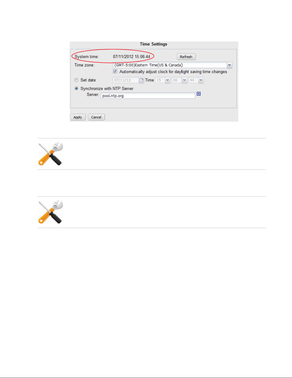
you may need to wait a couple of seconds, then click Refresh to update the display in
System time.)
If the NTP query fails, the system clock will continue without adjustment.
NTP on FortiRecorder complies with RFC 5905. If the current system time differs greatly from
the actual time, NTP will adjust the clock slowly to avoid incongruous jumps in log message
timestamps and other time-dependent features. If you want the time to be corrected
immediately, set the time zone and time manually first, then switch to NTP.
If FortiRecorder’s time was 3 hours late, for example, and NTP fails, the time will still be
exactly 3 hours late. Verify your DNS server IPs, your NTP server IP or name, routing, and
that your firewalls or routers do not block or proxy UDP port 123.
NTP queries may fail until you have configured gateway and DNS settings. See “Configuring the
network settings”.
See also
• Connectivity issues
NVR configuration Page 27 FortiRecorder 2.4.2 Administration Guide

Configuring schedules
Schedules are used in several places:
• When configuring a user under System > Administrator > User Profile, schedules are used to
specify when the users can access the camera. For details, see “Configuring user accounts”
on page 54.
Note: For user access, schedule gaps are allowed. If not scheduled, then access is denied.
Scheduce overlaps are allowed. And one-time schedules take precedence over recurring
schedules.
• When configuring camera video settings under Camera > Configuration > Camera Profile,
schedules are used to specify when to use low or high quality video. For details, see
“Configuring camera profiles” on page 37.
Note: For video quality schedules, gaps and overlaps are not allowed. And one-time
schedules take precedence over recurring schedules.
• When configuring camera recording settings under Camera > Configuration > Camera
Profile, schedules are used to specify when to trigger the different types of recording. For
details, see “Configuring camera profiles” on page 37.
Note: For cameral recording schedules, gaps and overlaps are allowed. And one-time
schedules take precedence over recurring schedules.
• When configuring camera settings under Camera > Configuration > Camera, schedules are
used to specify when to use different camera settings, such as DNR level, brightness,
contrast, saturation, and sharpness. For details, see “Configuring cameras” on page 44.
Note: For cameral setting schedules, gaps are allowed. But overlaps are not allowed. And
one-time schedules take precedence over recurring schedules.
• When configuring camera notifications under Camera > Notification > Camera Notification,
schedules are used to control when to send out notifications. For details, see “Configuring
cameras to send notifications” on page 71.
Note: For camera notification schedules, overlaps are not allowed but gaps are allowed. And
one-time schedules take precedence over recurring schedules.
The default schedule is used when no schedules are selected or the selected schedules conflict
with each other.
You cannot create a recurring recording schedule where the hours vary by the day of the week,
but you can achieve the same effect if you create multiple schedules.
To configure schedules
1. Go to Schedule > Schedule.
2. Select New and configure the following settings.
Setting name Description
Name Enter a name for the schedule.
Description Optionally enter a description.
Type Select a schedule type:
• Recurring: the schedule happens at specified times on selected
days.
• One-time: the schedule happens only on a specific date and time.
NVR configuration Page 28 FortiRecorder 2.4.2 Administration Guide

Setting name Description
Days and Time Select the days you want the camera to begin recording if you have
selected the Recurring schedule type.
All day Select this option if you want to record all day long.
Start time/End
time
Select the start and end time for the recurring recording or the start
and end date for the one-time recording.
You can use the sunrise and sunset time for the start and end time.
The sunrise and sunset time is calculated by the FortiRecorder’s
latitude and longitude location. For details, see “Setting the sunrise
and sunset time” on page 29.
When using sunrise and sunset time, you can a plus or minus two
hour offset to compensate for lighting conditions specific locations.
Setting the sunrise and sunset time
When specifying schedules, you can use specific day and time, or the sunrise and sunset time.
To get the sunrise and sunset time
1. Go to Schedule > Schedule > Settings.
2. Enter the latitude and longitude values of the FortiRecorder and camera location.
3. Click Calculate to retrieve the sunrise and sunset time. A few days’ sunrise and sunset time
will be displayed.
When using a combination of sunrise/sunset and the specific time, if the time cross the
boundary of sunrise/sunset, the schedule has no effect. For example, if the sunrise is at 8:00AM
and you set the schedule from sunrise to 7:00AM, the schedule has no effect.
Advanced/optional NVR configuration
After you have a basic working setup, depending on your specific requirements, you may want
to configure some advanced or optional settings.
• Configuring system timeout, ports, and public access
• Configuring FortiRecorder system appearance
• Configuring logging
• Alert email
Configuring system timeout, ports, and public access
Go to System > Configuration > Options to configure the system idle timeout, the HTTP, HTTPS,
SSH, Telnet, and FortiRecorder Central access ports, and the host name for public/remote
access.
If you want remote access — connecting from a home or a branch office through the Internet to
your FortiRecorder NVR— for either using the web UI or snapshot notification video clips while
you are out of the office, you must configure both your network and the NVR.
NVR configuration Page 29 FortiRecorder 2.4.2 Administration Guide

First, on your office’s firewall or Internet router, configure port forwarding and/or a virtual IP (VIP)
to forward remote access connections from the Internet to your FortiRecorder NVR’s private
network IP. (See “Appendix A: Port numbers”.)
Remote access opens ports and can weaken the strength of your network security. To prevent
attackers on the Internet from gaining access to your surveillance system, configure your
firewall or router to require authentication, restrict which IP addresses can use your port
forward/virtual IP, and scan requests for viruses and hacking attempts.
If you are not sure what your network’s Internet address is, while connected to your office
network, you can use an online utility such as:
http://ping.eu/
Next, go to System > Configuration > Options and configure these settings:
Setting name Description
Public Access
Host name Type either your network’s IP on the Internet, or its domain
name, such as www.example.com.
This is either your Internet router’s WAN IP, or a virtual IP (VIP)
on your firewall whose NAT table will forward incoming
connections from this public network IP to your FortiRecorder
NVR’s private network IP.
HTTP/ HTTPS
Port number
FortiRecorder supports live streaming (HLS) for mobile devices. You can use the FortiRecorder
Mobile drop-down menu to enable live streaming over HTTP or HTTPS.
Type the port number, such as 8080, on your public IP that your
Internet router or firewall will redirect to your FortiRecorder
NVR’s listening port.
About FortiRecorder logical interfaces
In addition to the physical interfaces, you can create the following types of logical interfaces on
FortiRecorder:
• VLAN subinterfaces
• Redundant interfaces
• Aggregate interfaces
• Loopback interfaces
VLAN subinterfaces
A Virtual LAN (VLAN) subinterface, also called a VLAN, is a virtual interface on a physical
interface. The subinterface allows routing of VLAN tagged packets using that physical interface,
but it is separate from any other traffic on the physical interface.
Virtual LANs (VLANs) use ID tags to logically separate devices on a network into smaller
broadcast domains. These smaller domains forward packets only to devices that are part of that
VLAN domain. This reduces traffic and increases network security.
NVR configuration Page 30 FortiRecorder 2.4.2 Administration Guide
 Loading...