

Page 1

INSTALL GUIDE
FortiGate-3000 and
FortiGate-3600
FortiOS 3.0MR4
www.fortinet.com
Page 2

FortiGate-3000 and FortiGate-3600 Install Guide
!
FortiOS 3.0MR4
15 February 2007
01-30004-0270-20070215
© Copyright 2007 Fortinet, Inc. All rights reserved. No part of this
publication including text, examples, diagrams or illustrations may be
reproduced, transmitted, or translated in any form or by any means,
electronic, mechanical, manual, optical or otherwise, for any purpose,
without prior written permission of Fortinet, Inc.
Trademarks
Dynamic Threat Prevention System (DTPS), APSecure, FortiASIC,
FortiBIOS, FortiBridge, FortiClient, FortiGate, FortiGate Unified Threat
Management System, FortiGuard, FortiGuard-Antispam, FortiGuardAntivirus, FortiGuard-Intrusion, FortiGuard-Web, FortiLog, FortiAnalyzer,
FortiManager, Fortinet, FortiOS, FortiPartner, FortiProtect, FortiReporter,
FortiResponse, FortiShield, FortiVoIP, and FortiWiFi are trademarks of
Fortinet, Inc. in the United States and/or other countries. The names of
actual companies and products mentioned herein may be the trademarks
of their respective owners.
Regulatory compliance
FCC Class A Part 15 CSA/CUS
Caution: Risk of Explosion if Battery is replaced by an Incorrect Type.
Dispose of Used Batteries According to the Instructions.
Page 3

Contents
Contents
Contents.............................................................................................. 3
Introduction ........................................................................................ 7
About the FortiGate units ................................................................................. 7
FortiGate-3000 .............................................................................................. 7
FortiGate-3600 .............................................................................................. 8
Register your FortiGate unit .......................................................................... 8
Fortinet Family Products .................................................................................. 8
FortiGuard Subscription Services ................................................................. 8
FortiClient...................................................................................................... 9
FortiMail ........................................................................................................ 9
FortiAnalyzer ................................................................................................. 9
FortiReporter ................................................................................................. 9
FortiBridge................................................................................................... 10
FortiManager............................................................................................... 10
About this document....................................................................................... 10
Document conventions................................................................................ 10
Typographic conventions...................................................................... 11
FortiGate documentation ................................................................................ 11
Fortinet Tools and Documentation CD ........................................................ 12
Fortinet Knowledge Center ......................................................................... 12
Comments on Fortinet technical documentation......................................... 12
Customer service and technical support ...................................................... 13
Installing the FortiGate unit ............................................................ 15
Package Contents............................................................................................ 15
FortiGate-3000 ............................................................................................ 15
Mounting ............................................................................................... 16
FortiGate-3600 ............................................................................................ 16
Mounting ............................................................................................... 17
Air Flow ....................................................................................................... 17
Mechanical loading ..................................................................................... 17
Powering on the FortiGate unit ...................................................................... 17
Powering off the FortiGate unit ................................................................... 19
Connecting the FortiGate unit ........................................................................ 19
Web-based manager................................................................................... 19
Front control buttons and LCD .................................................................... 19
Command line interface .............................................................................. 19
Connecting to the web-based manager ...................................................... 20
Connecting to the web-based manager using port 1 ............................ 20
Connecting to the web-based manager using the internal interface..... 21
FortiGate-3000 and FortiGate-3600 FortiOS 3.0MR4 Install Guide
01-30004-0270-20070215 3
Page 4

Contents
System Dashboard ............................................................................... 22
Connecting to the CLI ................................................................................. 22
LCD front control buttons............................................................................... 23
Using the front control buttons and LCD ..................................................... 23
Factory defaults ............................................................................... 25
Factory default NAT/Route mode network configuration ............................ 26
Factory default Transparent mode network configuration........................... 27
Factory default firewall configuration .......................................................... 27
Factory default protection profiles............................................................... 28
Restoring the default settings........................................................................ 28
Restoring the default settings using the web-based manager .................... 29
Restoring the default settings using the CLI ............................................... 29
Configuring the FortiGate unit........................................................ 31
Planning the FortiGate configuration ............................................................ 31
NAT/Route mode ........................................................................................ 31
NAT/Route mode with multiple external network connections .................... 32
Transparent mode....................................................................................... 33
Preventing the public FortiGate interface from responding to ping requests
34
NAT/Route mode installation ......................................................................... 35
Preparing to configure the FortiGate unit in NAT/Route mode ................... 35
DHCP or PPPoE configuration ................................................................... 36
Using the web-based manager ................................................................... 37
Configuring basic settings .................................................................... 37
Adding a default route .......................................................................... 38
Verifying the web-based manager configuration .................................. 38
Verify the connection ............................................................................ 38
Using the front control buttons and LCD ..................................................... 38
Adding a default gateway using the LCD ............................................. 39
Verifying the front control buttons and LCD configuration .................... 40
Verify the connection ............................................................................ 40
Using the command line interface............................................................... 40
Configuring the FortiGate unit to operate in NAT/Route mode............. 40
Adding a default route .......................................................................... 42
Verifying the CLI configuration ............................................................. 42
Verify the connection ............................................................................ 42
Connecting the FortiGate unit to the network(s) ......................................... 43
Configuring the networks ............................................................................ 43
Transparent mode installation ....................................................................... 44
Preparing to configure Transparent mode .................................................. 44
Using the web-based manager ................................................................... 44
Using the front control buttons and LCD ..................................................... 45
Adding a default gateway using the LCD ............................................. 46
FortiGate-3000 and FortiGate-3600 FortiOS 3.0MR4 Install Guide
4 01-30004-0270-20070215
Page 5

Contents
Verifying the front control buttons and LCD configuration .................... 46
Verify connection .................................................................................. 46
Using the command line interface............................................................... 46
Reconnecting to the web-based manager ............................................ 47
Connecting the FortiGate unit to your network............................................ 47
Verify the connection ............................................................................ 48
Next steps......................................................................................................... 48
Set the date and time .................................................................................. 48
Updating antivirus and IPS signatures ........................................................ 49
Updating antivirus and IPS signatures from the web-based manager.. 50
Updating the IPS signatures from the CLI ............................................ 50
Scheduling antivirus and IPS updates .................................................. 50
Adding an override server..................................................................... 51
FortiGate Firmware .......................................................................... 53
Upgrading to a new firmware version............................................................ 53
Upgrading the firmware using the web-based manager ............................. 53
Upgrading the firmware using the CLI......................................................... 54
Reverting to a previous firmware version ..................................................... 55
Reverting to a previous firmware version using the web-based manager .. 55
Reverting to a previous firmware version using the CLI.............................. 56
Installing firmware images from a system reboot using the CLI ................ 57
Restoring the previous configuration........................................................... 59
Testing a new firmware image before installing it........................................ 60
Index.................................................................................................. 63
FortiGate-3000 and FortiGate-3600 FortiOS 3.0MR4 Install Guide
01-30004-0270-20070215 5
Page 6

Contents
FortiGate-3000 and FortiGate-3600 FortiOS 3.0MR4 Install Guide
6 01-30004-0270-20070215
Page 7
Introduction About the FortiGate units
Introduction
Welcome and thank you for selecting Fortinet products for your real-time network
protection.
The FortiGate™ Unified Threat Management System improves network security,
reduces network misuse and abuse, and helps you use communications
resources more efficiently without compromising the performance of your
network. FortiGate Unified Threat Management Systems are ICSA-certified for
firewall, IPSec, and antivirus services.
The FortiGate Unified Threat Management Systemis a dedicated, easily managed
security device that delivers a full suite of capabilities, which include:
• application-level services such as virus protection and content filtering
• network-level services such as firewall, intrusion detection, VPN and traffic
shaping
The FortiGate Unified Threat Management System uses Fortinet’s Dynamic
Threat Prevention System (DTPS™) technology, which leverages breakthroughs
in chip design, networking, security and content analysis. The unique ASIC-based
architecture analyzes content and behavior in real-time, enabling key applications
to be deployed right at the network edge where they are most effective at
protecting your networks.
About the FortiGate units
The FortiGate-3000 and FortiGate-3600 provides carrier-class levels of
performance and reliability demanded by large enterprises and service providers.
Both the FortiGate-3000 and FortiGate-3600 meet the needs of the most
demanding applications, including redundant power supplies to minimize
single-point failures. The easy management of both units is a natural choice for
managed service offerings.
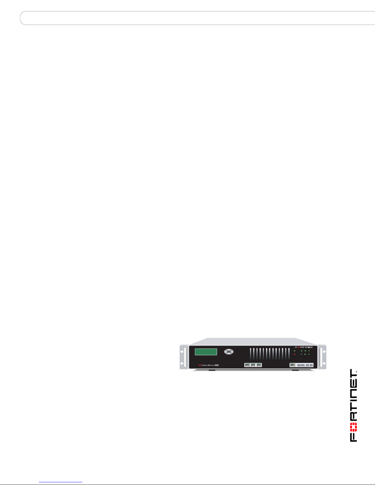
FortiGate-3000
The FortiGate-3000
provides the
carrier-class levels of
performance and
reliability demanded
by large enterprises
and service providers.
The unit uses multiple CPUs and FortiASIC chips to deliver a throughput of
3Gbps, meeting the needs of the most demanding applications. The
FortiGate-3000 includes redundant power supplies to minimize single-point
failures, including load-balanced operation and redundant failover with no
interruption in service. The high capacity, reliability, and easy management of the
FortiGate-3000 makes it a natural choice for managed service offerings.
Esc Enter
POWER
12
Hi-Temp
INT
4/HA
123 4/HA INTERNAL EXTERNAL
3
EXT
FortiGate-3000 and FortiGate-3600 FortiOS 3.0MR4 Install Guide
01-30004-0270-20070215 7
Page 8

Fortinet Family Products Introduction
FortiGate-3600
The FortiGate-3600 provides
carrier-class levels of
performance and reliability
demanded by large
Esc Enter
2
1
3 4 5/HA
POWER
Hi-Temp 4
INTERNAL EXTERNAL
12
3
5/HA
EXT
INT
enterprises and service
providers. The unit uses
multiple CPUs and
FortiASIC chips to deliver throughput of 4Gbps, meeting the needs of the most
demanding applications. The FortiGate-3600 includes redundant power supplies,
which minimize single-point failures, and supports load-balanced operation. The
high-capacity, reliability and easy management makes the FortiGate-3600 a
natural choice for managed service offerings.
Register your FortiGate unit
After installing a new FortiGate unit, register the unit by visiting
http://support.fortinet.com and select Product Registration.
To register, enter your contact information and the serial numbers of the FortiGate
units that you or your organization have purchased. You can register multiple
FortiGate units in a single session without re-entering your contact information.
By registering your FortiGate unit, you will receive updates to threat detection and
prevention databases (Antivirus, Intrusion Detection, etc.) and will also ensure
your access to technical support.
Fortinet Family Products
Fortinet offers a family of products that includes both software and hardware
appliances, for a complete network security solution including mail, logging,
reporting, network management, and security along with FortiGate Unified Threat
Management Systems. For more information on the Fortinet product family, go to
www.fortinet.com/products.
FortiGuard Subscription Services
FortiGuard Subscription Services are security services created, updated and
managed by a global team of Fortinet security professionals. They ensure the
latest attacks are detected and blocked before harming your corporate resources
or infecting your end-user computing devices. These services are created with the
latest security technology and designed to operate with the lowest possible
operational costs.
FortiGuard Subscription Services includes:
• FortiGuard Antivirus Service
• FortiGuard Intrusion Prevention subscription services (IPS)
• FortiGuard Web Filtering
• FortiGuard Antispam Service
• FortiGuard Premier Service
An online virus scanner and virus encyclopedia is also available for your
reference.
FortiGate-3000 and FortiGate-3600 FortiOS 3.0MR4 Install Guide
8 01-30004-0270-20070215
Page 9

Introduction Fortinet Family Products
FortiClient
FortiClient™ Host Security software provides a secure computing environment for
both desktop and laptop users running the most popular Microsoft Windows
operating systems. FortiClient offers many features including:
• creating VPN connections to remote networks
• configuring real-time protection against viruses
• guarding against modification of the Windows registry
• virus scanning
FortiClient also offers a silent installation feature, enabling an administrator to
efficiently distribute FortiClient to several users’ computers with preconfigured
settings.
FortiMail
FortiMail™ Secure Messaging Platform provides powerful, flexible heuristic
scanning and reporting capabilities to incoming and outgoing email traffic. The
FortiMail unit has reliable, high performance features for detecting and blocking
malicious attachments such as Distributed Checksum Clearinghouse (DCC)
scanning and Bayesian scanning. Built on Fortinet’s award winning FortiOS and
FortiASIC technology, FortiMail antivirus technology extends full content
inspection capabilities to detect the most advanced email threats.
FortiAnalyzer
FortiReporter
FortiAnalyzer™ provides network administrators with the information they need to
enable the best protection and security for their networks against attacks and
vulnerabilities. The FortiAnalyzer unit features include:
• collects logs from FortiGate] devices and syslog devices
• creates hundreds of reports using collected log data
• scans and reports vulnerabilities
• stores files quarantined from a FortiGate unit
The FortiAnalyzer unit can also be configured as a network analyzer to capture
real-time traffic on areas of your network where firewalls are not employed. You
can also use the unit as a storage device where users can access and share files,
including the reports and logs that are saved on the FortiAnalyzer hard disk.
FortiReporter™ Security Analyzer software generates easy-to-understand reports
and can collect logs from any FortiGate unit, as well as over 30 network and
security devices from third-party vendors. FortiReporter reveals network abuse,
manages bandwidth requirements, monitors web usage, and ensures employees
are using the office network appropriately. FortiReporter allows IT administrators
to identify and respond to attacks, including identifying ways to proactively secure
their networks before security threats arise.
FortiGate-3000 and FortiGate-3600 FortiOS 3.0MR4 Install Guide
01-30004-0270-20070215 9
Page 10

About this document Introduction
!
FortiBridge
FortiBridge™ products are designed to provide enterprise organizations with
continuous network traffic flow in the event of a power outage or a FortiGate
system failure. The FortiBridge unit bypasses the FortiGate unit to make sure that
the network can continue processing traffic. FortiBridge products are easy to use
and deploy, and you can customize the actions a FortiBridge unit takes when a
power failure or a FortiGate system failure occurs.
FortiManager
The FortiManager™ system is designed to meet the needs of large enterprises
(including managed security service providers) responsible for establishing and
maintaining security policies across many dispersed FortiGate installations. With
this system, you can configure multiple FortiGate devices and monitor their status.
You can also view real-time and historical logs for the FortiGate devices, including
updating firmware images of managed FortiGate devices. The FortiManager
System emphasizes ease of use, including easy integration with third party
systems.
About this document
This document explains how to install and configure your FortiGate unit onto your
network. This document also includes how to install and upgrade new firmware
versions on your FortiGate unit.
This document contains the following chapters:
• Installing the FortiGate unit – Describes setting up and powering on a
FortiGate unit.
• Factory defaults – Provides the factory default settings for the FortiGate unit.
• Configuring the FortiGate unit – Provides an overview of the operating modes
of the FortiGate unit and how to integrate the FortiGate unit into your network.
• FortiGate Firmware – Describes how to install, update, restore and test
firmware for the FortiGate device.
Document conventions
The following document conventions are used in this guide:
• In the examples, private IP addresses are used for both private and public IP
addresses.
• Notes and Cautions are used to provide important information:
Note: Highlights useful additional information.
Caution: Warns you about commands or procedures that could have unexpected or
undesirable results including loss of data or damage to equipment.
FortiGate-3000 and FortiGate-3600 FortiOS 3.0MR4 Install Guide
10 01-30004-0270-20070215
Page 11

Introduction FortiGate documentation
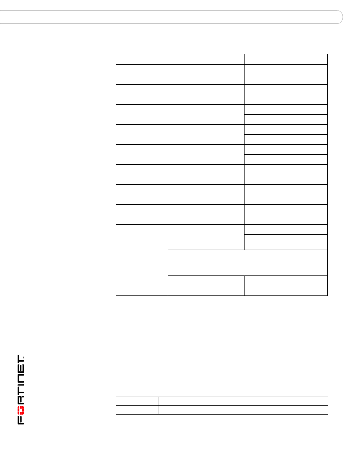
Typographic conventions
FortiGate documentation uses the following typographical conventions:
Convention Example
Keyboard input In the Gateway Name field, type a name for the remote VPN
Code examples config sys global
CLI command syntax config firewall policy
Document names FortiGate Administration Guide
Menu commands Go to VPN > IPSEC > Phase 1 and select Create New.
Program output Welcome!
Varia bles
peer or client (for example, Central_Office_1).
set ips-open enable
end
edit id_integer
set http_retry_count <retry_integer>
set natip <address_ipv4mask>
end
<address_ipv4>
FortiGate documentation
The most up-to-date publications and previous releases of Fortinet product
documentation are available from the Fortinet Technical Documentation web site
at http://docs.forticare.com.
The following FortiGate product documentation is available:
• FortiGate QuickStart Guide
Provides basic information about connecting and installing a FortiGate unit.
• FortiGate Install Guide
Describes how to install a FortiGate unit. Includes a hardware reference,
default configuration information, installation procedures, connection
procedures, and basic configuration procedures. Choose the guide for your
product model number.
• FortiGate Administration Guide
Provides basic information about how to configure a FortiGate unit, including
how to define FortiGate protection profiles and firewall policies; how to apply
intrusion prevention, antivirus protection, web content filtering, and spam
filtering; and how to configure a VPN.
• FortiGate online help
Provides a context-sensitive and searchable version of the Administration
Guide in HTML format. You can access online help from the web-based
manager as you work.
• FortiGate CLI Reference
Describes how to use the FortiGate CLI and contains a reference to all
FortiGate CLI commands.
FortiGate-3000 and FortiGate-3600 FortiOS 3.0MR4 Install Guide
01-30004-0270-20070215 11
Page 12

FortiGate documentation Introduction
• FortiGate Log Message Reference
Available exclusively from the Fortinet Knowledge Center, the FortiGate Log
Message Reference describes the structure of FortiGate log messages and
provides information about the log messages that are generated by FortiGate
units.
• FortiGate High Availability User Guide
Contains in-depth information about the FortiGate high availability feature and
the FortiGate clustering protocol.
• FortiGate IPS User Guide
Describes how to configure the FortiGate Intrusion Prevention System settings
and how the FortiGate IPS deals with some common attacks.
• FortiGate IPSec VPN User Guide
Provides step-by-step instructions for configuring IPSec VPNs using the webbased manager.
• FortiGate SSL VPN User Guide
Compares FortiGate IPSec VPN and FortiGate SSL VPN technology, and
describes how to configure web-only mode and tunnel-mode SSL VPN access
for remote users through the web-based manager.
• FortiGate PPTP VPN User Guide
Explains how to configure a PPTP VPN using the web-based manager.
• FortiGate Certificate Management User Guide
Contains procedures for managing digital certificates including generating
certificate requests, installing signed certificates, importing CA root certificates
and certificate revocation lists, and backing up and restoring installed
certificates and private keys.
• FortiGate VLANs and VDOMs User Guide
• Describes how to configure VLANs and VDOMS in both NAT/Route and
Transparent mode. Includes detailed examples.
Fortinet Tools and Documentation CD
All Fortinet documentation is available from the Fortinet Tools and Documentation
CD shipped with your Fortinet product. The documents on this CD are current at
shipping time. For up-to-date versions of Fortinet documentation see the Fortinet
Technical Documentation web site at http://docs.forticare.com.
Fortinet Knowledge Center
Additional Fortinet technical documentation is available from the Fortinet
Knowledge Center. The knowledge center contains troubleshooting and how-to
articles, FAQs, technical notes, and more. Visit the Fortinet Knowledge Center at
http://kc.forticare.com.
Comments on Fortinet technical documentation
Please send information about any errors or omissions in this document, or any
Fortinet technical documentation, to techdoc@fortinet.com.
FortiGate-3000 and FortiGate-3600 FortiOS 3.0MR4 Install Guide
12 01-30004-0270-20070215
Page 13

Introduction Customer service and technical support
Customer service and technical support
Fortinet Technical Support provides services designed to make sure that your
Fortinet systems install quickly, configure easily, and operate reliably in your
network.
Please visit the Fortinet Technical Support web site at http://support.fortinet.com
to learn about the technical support services that Fortinet provides.
FortiGate-3000 and FortiGate-3600 FortiOS 3.0MR4 Install Guide
01-30004-0270-20070215 13
Page 14

Customer service and technical support Introduction
FortiGate-3000 and FortiGate-3600 FortiOS 3.0MR4 Install Guide
14 01-30004-0270-20070215
Page 15
Installing the FortiGate unit Package Contents
Installing the FortiGate unit
This section provides information on installing and setting up the FortiGate unit on
your network. This section includes the following topics:
• Package Contents
• Air Flow
• Mechanical loading
• Powering on the FortiGate unit
• Connecting the FortiGate unit
Package Contents
Review the contents of your FortiGate package to ensure all components were
included.
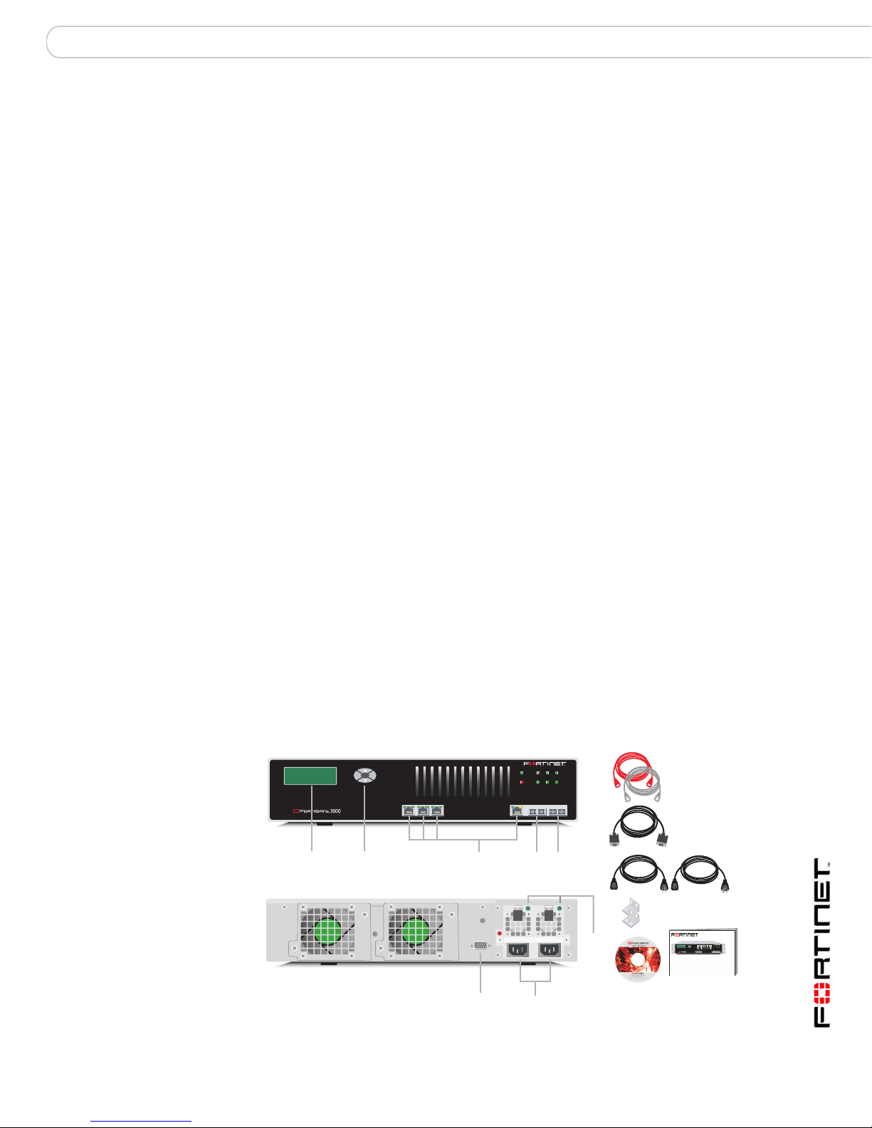
FortiGate-3000
The FortiGate-3000 package contains the following items:
• FortiGate-3000 Unified Threat Management System
• one orange crossover Ethernet cable (Fortinet part number CC300248)
• one gray straight-through Ethernet cable (Fortinet part number CC300249)
• one null-modem cable (Fortinet part number CC300247)
• two 19-inch rack mount brackets
• two power cables
• FortiGate-3000 QuickStart Guide
• Fortinet Tools and Documentation CD
Figure 1: FortiGate-3000 package contents
Front
POWER
12
LCD
Display
Esc Enter
Control
Buttons
Hi-Temp
INT
4/HA
123 4/HA INTERNAL EXTERNAL
1, 2, 3, 4/HA
Interface
Internal
Interface
External
Interface
Back
3
EXT
Ethernet Cables:
Orange - Crossover
Grey - Straight-through
Null-Modem Cable
(RS-232)
Power Cables (2)
FortiGate-3000 and FortiGate-3600 FortiOS 3.0MR4 Install Guide
01-30004-0270-20070215 15
RS-232 Serial
Connection
Power
Connections
Power
Supply
LEDs
Rack-Mount Brackets
USER MANUAL
Documentation
FortiGate-3000
Esc Enter
123 4/HA INTERNAL EXTERNAL
QuickStart Guide
Copyright 2003 Fortinet Incorporated. All rights reserved.
Trademarks
Products mentioned in this document are trademarks.
POWER
12
3
4/HA
INT
Hi-Temp
EXT
Page 16
Package Contents Installing the FortiGate unit
Mounting
The FortiGate-3000 unit can be mounted in a standard 19-inch rack. It requires
2 U of vertical space in the rack. The FortiGate-3000 unit can also be installed as
a free-standing appliance on any stable surface.
Table 1: Technical Specifications
Dimensions 16.75 x 13.5 x 3.5 in. (42.7 x 33 x 8.9 cm)
Weight 17.5 lb. (8 kg)
Power
requirements
Environmental
Specifications
Power dissipation: 360W (max.)
AC input voltage: 100 to 240 VAC
AC input current: 6A
Frequency: 50 to 60Hz
• The FortiGate-3000 unit may overload your supply circuit and impact
your overcurrent protection and supply wiring. Use appropriate
equipment nameplate ratings to address this concern.
• Make sure the FortiGate-3000 unit has reliable grounding. Fortinet
recommends direct connection to the branch circuit.
Operating temperature: 32 to 104 F (0 to 40 C)
Storage temperature: -13 to 158 F (-25 to 70 C)
Humidity: 5 to 95% non-condensing
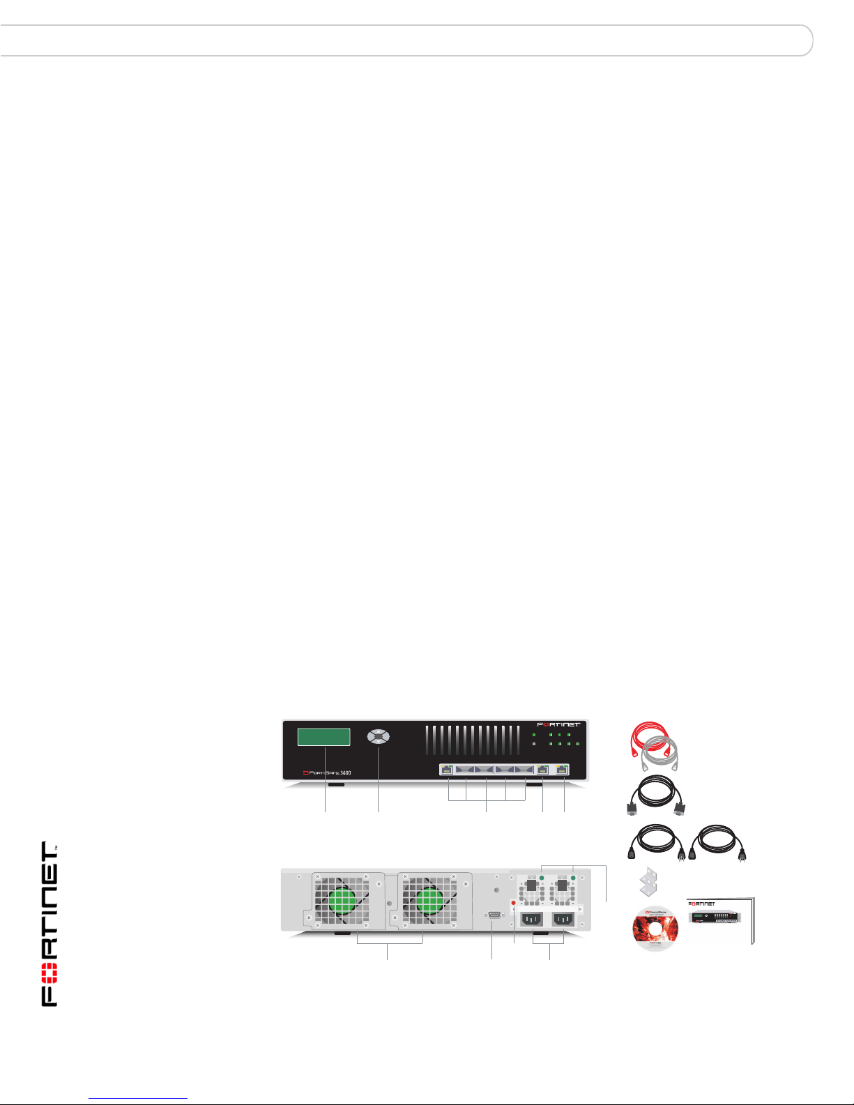
FortiGate-3600
• FortiGate-3600 Unified Threat Management System
• one orange crossover Ethernet cable (Fortinet part number CC300248)
• one gray regular Ethernet cable (Fortinet part number CC300249)
• one null-modem cable (Fortinet part number CC300247)
• two 19-inch rack mount brackets
• two power cables
• FortiGate-3600 QuickStart Guide
• Fortinet Tools and Documentation CD
Figure 2: FortiGate-3600 package contents
Front
POWER
12
3
5/HA
Hi-Temp 4
Hot Swappable
Power Supplies
INT
INTERNAL EXTERNAL
External
Interface
Redundant
EXT
Power
Supply
LEDs
Ethernet Cables:
Orange - Crossover
Grey - Straight-through
Rack-Mount Brackets
USER MANUAL
Null-Modem Cable
(RS-232)
Power Cables (2)
FortiGate-3600
Esc Enter
12345/HA
QuickStart Guide
Copyright 2003 Fortinet Incorporated. All rights reserved.
Trademarks
Products mentioned in this document are trademarks.
Documentation
LCD
Display
Esc Enter
Control
Buttons
Redundant
Hot-Swappable
Fan Assemblies
1
Back
RS-232 Serial
Connection
2
3 4 5/HA
1, 2, 3, 4, 5/HA
Interfaces
Alarm
Cancel
Button
Internal
Interface
12
POWER
3
Hi-Temp 4
5/HA
INT
EXT
INTERNALEXTERNAL
FortiGate-3000 and FortiGate-3600 FortiOS 3.0MR4 Install Guide
16 01-30004-0270-20070215
Page 17

Installing the FortiGate unit Powering on the FortiGate unit
Mounting
The FortiGate-3600 unit can be mounted in a standard 19-inch rack. It requires
2 U of vertical space in the rack. The FortiGate-3600 unit can also be installed as
a free-standing appliance on any stable surface.
Table 2: Technical Specifications
Dimensions 16.75 x 13.5 x 3.5 in. (42.7 x 33 x 8.9 cm)
Weight 17.5 lb. (8 kg)
Power
requirements
Environmental
Specifications
Power dissipation: 460W (max.)
AC input voltage: 100 to 240 VAC
AC input current: 6A
Frequency: 50 to 60Hz
• The FortiGate-3600 unit may overload your supply circuit and impact
your overcurrent protection and supply wiring. Use appropriate
equipment nameplate ratings to address this concern.
• Make sure the FortiGate-3600 unit has reliable grounding. Fortinet
recommends direct connection to the branch circuit.
Operating temperature: 32 to 104 F (0 to 40 C)
Storage temperature: -13 to 158 F (-25 to 70 C)
Humidity: 5 to 95% non-condensing
Air Flow
• For rack installation, make sure the amount of air flow required for safe
operation of the FortiGate unit is not compromised.
• For free-standing installation, make sure the FortiGate unit has at least 1.5 in.
(3.75 cm) of clearance on each side to allow for adequate air flow and cooling.
• If you install the FortiGate unit in a closed or multi-rack assembly, the
operating ambient temperature of the rack environment may be greater than
room ambient. Make sure the operating ambient temperature does not exceed
the manufacturer’s maximum rated ambient temperature.
Mechanical loading
For rack installation, make sure the mechanical loading of the FortiGate unit is
evenly distributed to avoid a hazardous condition.
Powering on the FortiGate unit
The FortiGate unit does not have an on/off switch.
To power on the FortiGate unit
1 Connect the power cables to the power connections on the back of the FortiGate
unit.
2 Connect the power cables to power outlets.
Each power cable should be connected to a different power source. If one power
source fails, the other may still be operative.
FortiGate-3000 and FortiGate-3600 FortiOS 3.0MR4 Install Guide
01-30004-0270-20070215 17
Page 18
Powering on the FortiGate unit Installing the FortiGate unit
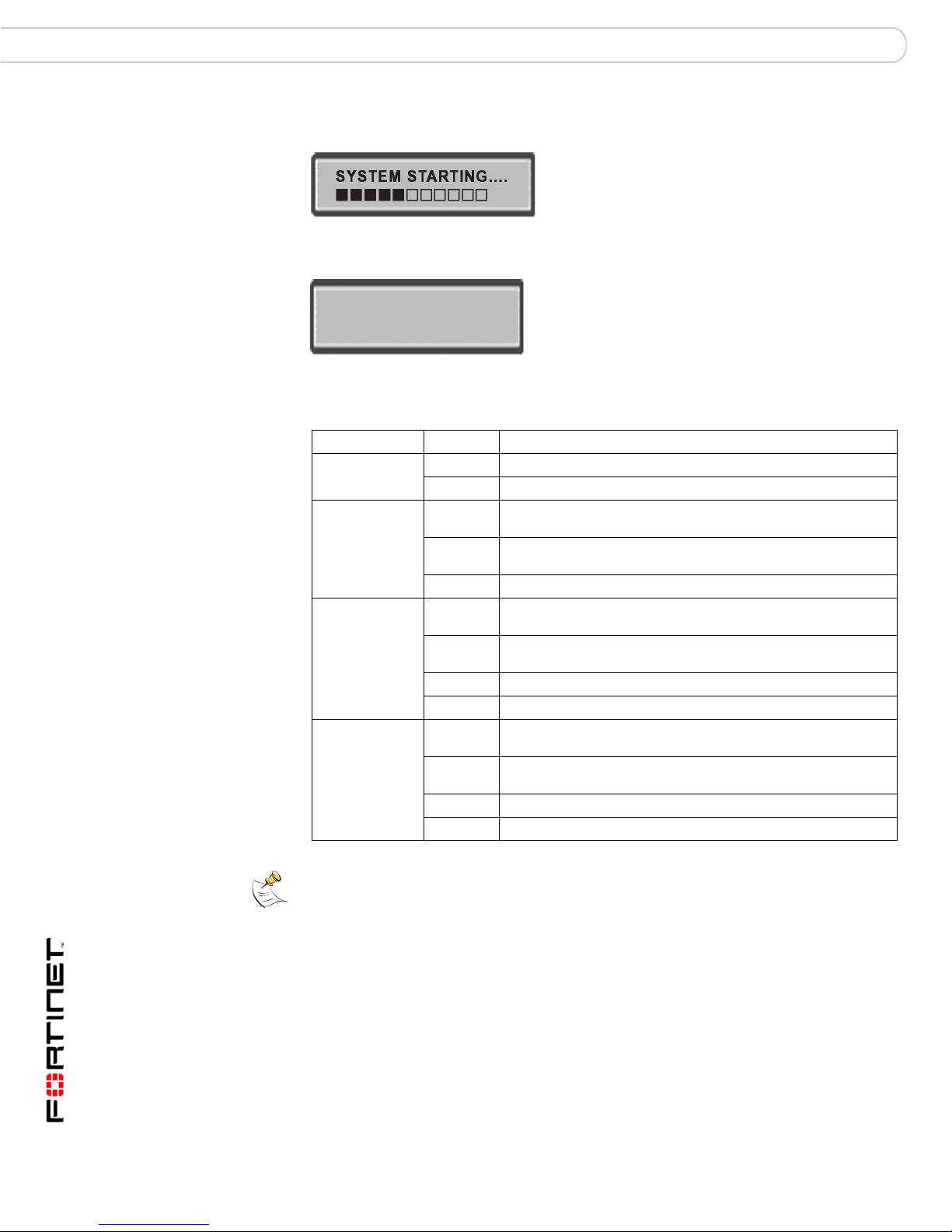
After a few seconds, SYSTEM STARTING appears on the LCD.
The main menu setting appears on the LCD when the system is running.
Menu [ Fortigat -> ]
NAT, Standalone
The FortiGate unit starts and the Power LEDs light up.
Table 3: LED indicators
LED State Description
Power Green The FortiGate unit is powered on.
Off The FortiGate unit is powered off.
1, 2, 3, 4,
4/HA, 5/HA,
INT, EXT
1, 2, 3
(Interfaces)
(10/100
Interface)
Internal
External
(gigabit copper
Interfaces)
4/HA
(Interface)
Green The correct cable is in use, and the connected equipment has
Flashing
green
Off No link established.
Green The correct cable is in use, and the connected equipment has
Flashing
Green
Green The interface is connected at 100 Mbps.
Off No link established.
Amber The correct cable is in use, and the connected equipment has
Flashing
amber
Green The interface is connected at 1000 Mbps.
Off No link established.
power.
Network activity at this interface.
power.
Network activity at this interface.
power.
Network activity at this interface.
Note: If only one power supply is connected, an audible alarm sounds to indicate a failed
power supply. Press the red alarm cancel button on the rear panel next to the power supply
to stop the alarm.
FortiGate-3000 and FortiGate-3600 FortiOS 3.0MR4 Install Guide
18 01-30004-0270-20070215
Page 19

Installing the FortiGate unit Connecting the FortiGate unit
Powering off the FortiGate unit
Always shut down the FortiGate operating system properly before turning off the
power switch to avoid potential hardware problems.
To power off the FortiGate unit
1 From the web-based manager, go to System > Status.
2 In the Unit Operation display, select Shutdown, or from the CLI enter:
execute shutdown
3 Disconnect the power cables from the power supply.
Connecting the FortiGate unit
There are three methods of connecting and configuring the basic FortiGate
settings:
• the web-based manager
• the front control buttons and LCD
• the command line interface (CLI)
Web-based manager
You can configure and manage the FortiGate unit using HTTP or a secure HTTPS
connection from any computer running Microsoft Internet Explorer 6.0 or recent
browser. The web-based manager supports multiple languages.
Use the web-based manager to configure most FortiGate settings, and monitor
the status of the FortiGate unit.
Front control buttons and LCD
You can use the front control buttons and LCD on the FortiGate unit to configure
IP addresses, default gateways and switch operating modes. The LCD shows you
what mode you are in without having to go to the command line interface or the
web-based manager. For more information on the front control buttons and LCD,
see “LCD front control buttons” on page 23.
Command line interface
You can access the FortiGate command line interface (CLI) by connecting a
management computer serial port to the FortiGate serial console connector. You
can also use Telnet or a secure SSH connection to connect to the CLI from any
network that is connected to the FortiGate unit, including the Internet.
FortiGate-3000 and FortiGate-3600 FortiOS 3.0MR4 Install Guide
01-30004-0270-20070215 19
Page 20

Connecting the FortiGate unit Installing the FortiGate unit
Connecting to the web-based manager
Use the following procedure to connect to the web-based manager for the first
time. Configuration changes made with the web-based manager are effective
immediately, without resetting the firewall or interrupting service.
To connect to the web-based manager, you require:
• a computer with an Ethernet connection
• Microsoft Internet Explorer version 6.0 or higher or any recent version of the
most popular web browser
• a crossover Ethernet cable or an Ethernet hub and two Ethernet cables
Note: Before starting Internet Explorer, (or any recent version of the most popular web
browser), ping to your FortiGate unit to see if the connection between the computer and the
FortiGate unit is working properly.
Connecting to the web-based manager using port 1
You can use the port 1 interface to connect to the web-based manager. The port 1
interface can be used as an optional interface on the FortiGate-3000 when there
is no optical network to connect to the internal interface.
To connect to the web-based manager using port 1
1 Connect to the FortiGate-3000 command line interface (CLI). See “Connecting to
the CLI” on page 22.
2 Set the IP address and netmask of Port 1 to an IP address you can connect to a
computer with an Ethernet connection, and set the administrative access to
HTTPS.
config system interface
edit port1
set ip <address_ip> <netmask>
set allowaccess https
end
Example
To set the IP address of Port 1 to 192.168.20.99 and netmask to 255.255.255.0
and set administrative access to HTTPS, enter:
config system interface
edit port1
set ip 192.168.20.99. 255.255.255.0
set allowaccess https
end
3 Set the IP address of the computer with an Ethernet connection to a static IP
address on the same subnet as Port 1.
4 Using the crossover cable (or the Ethernet hub and cables), connect Port 1 of the
FortiGate unit to the computer Ethernet connection.
FortiGate-3000 and FortiGate-3600 FortiOS 3.0MR4 Install Guide
20 01-30004-0270-20070215
Page 21

Installing the FortiGate unit Connecting the FortiGate unit
Connecting to the web-based manager using the internal
interface
The FortiGate-3000 can connect to an optical network using the internal interface
to browse to the web-based manager.
Use the following procedure for the FortiGate-3600.
To connect to the web-based manager using the internal interface
1 Set the IP address of the computer with an Ethernet connection to the static IP
address 192.168.1.2 with a netmask of 255.255.255.0.
2 Connect the internal interface of the FortiGate unit to your optical network.
3 Connect the interface of the computer to the same network.
4 Start Internet Explorer and browse to the address https://192.168.1.99 (remember
to include the “s” in https://)
To support a secure HTTPS authentication method, the FortiGate unit ships with a
self-signed security certificate, and is offered to remote clients whenever they
initiate a HTTPS connection to the FortiGate unit. When you connect, the
FortiGate unit displays two security warnings in the browser.
The first warning prompts you to accept and optionally install the FortiGate unit’s
self-signed security certificate. If you do not accept the certificate, the FortiGate
unit refuses the connection. If you accept the certificate, the FortiGate login page
appears. The credentials entered are encrypted before they are sent to the
FortiGate unit. If you choose to accept the certificate permanently, the warning is
not displayed again.
Just before the FortiGate login page is displayed, a second warning informs you
that the FortiGate certificate distinguished name differs from the original request.
This warning occurs because the FortiGate unit redirects the connection. This is
an informational message. Select OK to continue logging in.
Figure 3: FortiGate login
5 Type admin in the Name field and select Login.
FortiGate-3000 and FortiGate-3600 FortiOS 3.0MR4 Install Guide
01-30004-0270-20070215 21
Page 22

Connecting the FortiGate unit Installing the FortiGate unit
System Dashboard
After logging into the web-based manager, the web browser displays the system
dashboard. The dashboard provides you with all system status information in one
location. For details on the information displayed on the dashboard, see the
FortiGate Administration Guide.
Connecting to the CLI
As an alternative to the web-based manager, you can install and configure the
FortiGate unit using the CLI. Configuration changes made with the CLI are
effective immediately, without resetting the firewall or interrupting service.
To connect to the FortiGate CLI you require:
• a computer with an available communications port
• the null-modem cable included in your FortiGate package
• terminal emulation software such as HyperTerminal for Microsoft Windows
Note: The following procedure uses Microsoft Windows HyperTerminal software. You can
apply these steps to any terminal emulation program.
To connect to the CLI
1 Connect the null-modem cable to the communications port of your computer and
to the FortiGate console port.
2 Start HyperTerminal, enter a name for the connection, and select OK.
3 Configure HyperTerminal to connect directly to the communications port on your
computer and select OK.
4 Select the following port settings and select OK:
Bits per second 9600
Data bits 8
Parity None
Stop bits 1
Flow control None
5 Press Enter to connect to the FortiGate CLI.
The login prompt appears.
6 Type admin and press Enter twice.
The following prompt is displayed:
Welcome!
Type ? to list available commands. For information about how to use the CLI, see
the FortiGate CLI Reference.
FortiGate-3000 and FortiGate-3600 FortiOS 3.0MR4 Install Guide
22 01-30004-0270-20070215
Page 23

Installing the FortiGate unit LCD front control buttons
LCD front control buttons
You can use the front control buttons and LCD to configure the basic settings on
your FortiGate unit. This configuration method provides an easy and fast method
to configure your FortiGate unit. You can configure:
• IP addresses
• netmasks
• default gateways
• operating modes
• restore factory default settings
The LCD provides information on the FortiGate unit’s operating mode and
whether or not it is part of a High Availability (HA) cluster. Figure 4 shows the
default LCD main menu setting of a FortiGate unit, operating in NAT/Route mode
and not connected to a HA cluster.
Figure 4: Default LCD main menu settings
Menu [ Fortigat -> ]
NAT, Standalone
Table 4: LCD main menu definitions
Menu The menu the LCD currently displays.
[Fortigat ->] The FortiGate unit’s host name.
NAT The current operational mode of the FortiGate unit.
Standalone The FortiGate unit is not part of a HA cluster. For more information
on standalone mode and HA, see the FortiGate Administration
Guide.
The front control buttons control how you enter and exit the different menus when
configuring the different ports and interfaces. The front control buttons also
enables you to increase or decrease each number for configuring IP addresses,
default gateway addresses, or netmasks. The following table defines each button
and what it does when configuring the basic settings of your FortiGate unit.
Table 5: Front control button definitions
Enter Enables you to move forward through the configuration process.
Esc Enables you to move backward, or exit out of the menu you are in.
Up Allows you to increase the number for an IP address, default gateway address
Down Allows you to decrease the number for an IP address, default gateway
or netmask.
address or netmask.
Using the front control buttons and LCD
When the LCD displays the main menu setting, you can begin to configure the IP
addresses, netmasks, default gateways, and if required, change the operating
mode. Use the following procedures as a guide when configuring your FortiGate
unit in “Configuring the FortiGate unit” on page 31.
FortiGate-3000 and FortiGate-3600 FortiOS 3.0MR4 Install Guide
01-30004-0270-20070215 23
Page 24

LCD front control buttons Installing the FortiGate unit
To enter an IP address
1 Press Enter to select the interfaces.
2 Press the up and down buttons to highlight the interface you want to configure an
IP address for, and then press Enter.
3 Press Enter for the IP address.
4 Press the up and down buttons to increase or decrease the number.
5 Press Enter to select the number.
6 Repeat steps 4 and 5 for all numbers of the IP address.
Use the above steps to configure netmasks and default gateways.
To change the operating mode
1 Make sure the LCD displays the main menu setting.
2 Press Enter to select the interfaces.
3 Press the up and down buttons to highlight the menu Change to bridge mode.
4 Press Enter to change to Transparent mode.
The FortiGate unit changes to Transparent mode. This may take a few minutes.
5 The LCD should display the following:
Figure 5: LCD main menu setting for Transparent mode
To reset to factory defaults
1 Make sure the LCD displays the main menu setting.
2 Press Enter to go to the interfaces.
3 Press the up and down arrows to highlight the menu Restore Defaults.
4 Press Enter.
The FortiGate unit resets to factory default settings. This may take a few minutes.
FortiGate-3000 and FortiGate-3600 FortiOS 3.0MR4 Install Guide
24 01-30004-0270-20070215
Page 25

Factory defaults
Factory defaults
The FortiGate unit ships with a factory default configuration. The default
configuration allows you to connect to and use the FortiGate web-based manager
to configure the FortiGate unit onto the network. To configure the FortiGate unit on
to the network you add an administrator password, change the network interface
IP addresses, add DNS server IP addresses, and, if required, configure basic
routing.
If you plan to operate the FortiGate unit in Transparent mode, you can switch to
Transparent mode from the factory default configuration and then configure the
FortiGate unit onto the network in Transparent mode.
Once you complete the network configuration, you can perform additional
configuration tasks such as setting system time, configuring virus and attack
definition updates, and registering the FortiGate unit.
The factory default firewall configuration includes a single network address
translation (NAT) policy that allows users on your internal network to connect to
the external network and stops users on the external network from connecting to
the internal network. You can add more firewall policies to provide more control of
the network traffic passing through the FortiGate unit.
The factory default protection profiles can be used to apply different levels of
antivirus protection, web content filtering, spam filtering, and IPS to the network
traffic controlled by firewall policies.
The following topics are included in this section:
• Factory default NAT/Route mode network configuration
• Factory default Transparent mode network configuration
• Factory default firewall configuration
• Factory default protection profiles
• Restoring the default settings
FortiGate-3000 and FortiGate-3600 FortiOS 3.0MR4 Install Guide
01-30004-0270-20070215 25
Page 26

Factory default NAT/Route mode network configuration
When the FortiGate unit is first powered on, it is running in NAT/Route mode and
has the basic network configuration listed in Table 6 on page 26. This
configuration enables you to connect to the FortiGate unit web-based manager
and establish the configuration required to connect the FortiGate unit to the
network. In Table 6 on page 26, HTTPS administrative access means you can
connect to the web-based manager using HTTPS protocol through this interface.
Ping administrative access means this interface responds to ping requests.
Table 6: Factory default NAT/Route mode network configuration
Factory defaults
Administrative
account
Internal Interface Netmask: 255.255.255.0
External Interface Netmask: 255.255.255.0
Port 1 Netmask: 0.0.0.0
Port 2 Netmask: 0.0.0.0.
Port 3 Netmask: 0.0.0.0.
Port 4 Netmask: 0.0.0.0.
Port 4/HA and IP: 0.0.0.0.
Port 5/HA Netmask: 0.0.0.0.
User name: admin
Password: (none)
IP: 192.168.1.99
Administrative Access: HTTPS, Ping
IP: 192.168.100.99
Administrative Access: Ping
IP: 0.0.0.0.
Administrative Access: Ping
IP: 0.0.0.0.
Administrative Access: Ping
IP: 0.0.0.0.
Administrative Access: Ping
IP: 0.0.0.0.
Administrative Access: Ping
Administrative Access: Ping
Default Gateway (for default route) 192.168.100.1
Interface connected to external network
(for default route)
external
Default Route
Network Settings
26 01-30004-0270-20070215
A default route consists of a default gateway and the name of the
interface connected to the external network (usually the Internet).
The default gateway directs all non-local traffic to this interface
and to the external network.
Primary DNS: 65.39.139.53
Secondary DNS: 65.39.139.63
FortiGate-3000 and FortiGate-3600 FortiOS 3.0MR4 Install Guide
Page 27

Factory defaults
Factory default Transparent mode network configuration
In Transparent mode, the FortiGate unit has the default network configuration
listed in Table 7 on page 27.
Table 7: Factory default Transparent mode network configuration
Administrator
account
Management IP
DNS
Administrative access Port 2 Ping
User name: admin
Password: (none)
IP: 0.0.0.0
Netmask: 0.0.0.0
Primary DNS server: 65.39.139.53
Secondary DNS server: 65.39.139.63
Internal HTTPS, Ping
External Ping
Port 1 Ping
Port 3 Ping
Port 4 Ping
Port 4/HA Ping
Port 5/HA Ping
Factory default firewall configuration
FortiGate firewall policies control how all traffic is processed by the FortiGate unit.
Until firewall policies are added, no traffic can be accepted by or pass through the
FortiGate unit. To allow traffic through the FortiGate unit, you can add firewall
policies. See the FortiGate Administration Guide for information on adding firewall
policies.
The following firewall configuration settings are included in the default firewall
configuration to make it easier to add firewall policies.
Table 8: Factory default firewall configuration
Configuration setting Name Description
Firewall address All Firewall address matches the source or
Pre-defined service More than 50
Recurring schedule Always The recurring schedule is valid at any
Protection Profiles Strict, Scan, Web,
The factory default firewall configuration is the same in NAT/Route mode and
Transparent mode.
FortiGate-3000 and FortiGate-3600 FortiOS 3.0MR4 Install Guide
01-30004-0270-20070215 27
predefined services
Unfiltered
destination address of any packet.
Select from any of the 50 pre-defined
services to control traffic through the
FortiGate unit that uses that service.
time.
Control how the FortiGate unit applies
virus scanning, web content filtering, spam
filtering, and IPS.
Page 28

Restoring the default settings Factory defaults
!
Factory default protection profiles
Use protection profiles to apply different protection settings for traffic controlled by
firewall policies. You can use protection profiles to:
• configure antivirus protection for HTTP, FTP, IMAP, POP3, and SMTP firewall
policies
• configure Web filtering for HTTP firewall policies
• configure Web category filtering for HTTP firewall policies
• configure spam filtering for IMAP, POP3 and SMTP firewall policies
• enable the Intrusion Protection System (IPS) for all services
• enable content logging for HTTP, FTP, IMAP, POP3, and SMTP firewall
policies
By using protection profiles, you can build protection configurations that can be
applied to different types of firewall policies. This allows you to customize types
and levels of protection for different firewall policies.
For example, while traffic between internal and external addresses might need
strict protection, traffic between trusted internal addresses might need moderate
protection. You can configure firewall policies for different traffic services to use
the same or different protection profiles.
Protection profiles can be added to NAT/Route mode and Transparent mode
firewall policies.
The FortiGate unit comes preconfigured with four protection profiles.
Strict To apply maximum protection to HTTP, FTP, IMAP, POP3, and SMTP traffic.
Scan To apply antivirus scanning and file quarantining to HTTP, FTP, IMAP,
Web To apply antivirus scanning and web content blocking to HTTP content
Unfiltered To apply no scanning, blocking or IPS. Use if you do not want to apply
You may not use the strict protection profile under normal circumstances but
it is available if you have problems with viruses and require maximum
screening.
POP3, and SMTP content traffic.
traffic. You can add this protection profile to firewall policies that control
HTTP traffic.
content protection to content traffic. You can add this protection profile to
firewall policies for connections between highly trusted or highly secure
networks where content does not need to be protected.
Restoring the default settings
You can revert to the factory default settings if you mistakenly change a network
setting and cannot recover from it.
Caution: This procedure deletes all changes you have made to the FortiGate configuration
and reverses the system to its original configuration, including resetting interface
addresses.
FortiGate-3000 and FortiGate-3600 FortiOS 3.0MR4 Install Guide
28 01-30004-0270-20070215
Page 29

Factory defaults Restoring the default settings
Restoring the default settings using the web-based manager
To reset the default settings
1 Go to System > Status.
2 In the Unit Operation display, select Reset.
Restoring the default settings using the CLI
To reset the default settings enter the following command:
execute factoryreset
Note: If you want to restore factory default settings using the front control buttons and LCD,
see “LCD front control buttons” on page 23.
FortiGate-3000 and FortiGate-3600 FortiOS 3.0MR4 Install Guide
01-30004-0270-20070215 29
Page 30

Restoring the default settings Factory defaults
FortiGate-3000 and FortiGate-3600 FortiOS 3.0MR4 Install Guide
30 01-30004-0270-20070215
Page 31

Configuring the FortiGate unit Planning the FortiGate configuration
Configuring the FortiGate unit
This section provides an overview of the operating modes of the FortiGate unit.
Before beginning to configure the FortiGate unit, you need to plan how to
integrate the unit into your network. Your configuration plan depends on the
operating mode you select: NAT/Route mode or Transparent mode.
This section includes the following topics:
• Planning the FortiGate configuration
• Preventing the public FortiGate interface from responding to ping requests
• NAT/Route mode installation
• Transparent mode installation
• Next steps
Planning the FortiGate configuration
Before you configure the FortiGate unit, you need to plan how to integrate the unit
into the network. Among other things, you must decide whether you want the unit
to be visible to the network, which firewall functions you want it to provide, and
how you want it to control the traffic flowing between its interfaces.
Your configuration plan depends on the operating mode you select. You can
configure the FortiGate unit in one of two modes: NAT/Route mode (the default) or
Transparent mode.
You can also configure the FortiGate unit and the network it protects using the
default settings.
NAT/Route mode
In NAT/Route mode, the FortiGate unit is visible to the network. Like a router, all
its interfaces are on different subnets. The following interfaces are available in
NAT/Route mode:
Table 9: NAT/Route mode network segments
FortiGate Unit Internal Interface External Interface Other
FortiGate-3000 Internal External Port 2
FortiGate-3600 Internal External Port 1
Port 1, 3, 4
Port 4/HA
Port 2, 3, 4,
Port 5/HA
You can add firewall policies to control whether communications through the
FortiGate unit operate in NAT or Route mode. Firewall policies control the flow of
traffic based on the source address, destination address, and service of each
packet. In NAT mode, the FortiGate unit performs network address translation
before it sends the packet to the destination network. In Route mode, there is no
address translation.
FortiGate-3000 and FortiGate-3600 FortiOS 3.0MR4 Install Guide
01-30004-0270-20070215 31
Page 32

Planning the FortiGate configuration Configuring the FortiGate unit
You typically use NAT/Route mode when the FortiGate unit is operating as a
gateway between private and public networks. In this configuration, you would
create NAT mode firewall policies to control traffic flowing between the internal,
private network and the external, public network (usually the Internet).
Note: If you have multiple internal networks, such as a DMZ network in addition to the
internal, private network, you could create route mode firewall policies for traffic flowing
between them.
Figure 6: Example NAT/Route mode configuration.
Internal network
Internal
Internet
External
204.23.1.5
192.168.1.99
Port 3
10.10.10.2
Route mode policies
controlling traffic between
Internal networks.
DMZ network
192.168.1.3
NAT policies controlling
traffic between internal
and external networks.
NAT/Route mode with multiple external network connections
In NAT/Route mode, you can configure the FortiGate unit with multiple redundant
connections to the external network (usually the Internet).
For example, you could create the following configuration:
• External is the default interface to the external network (usually the Internet)
• Internal is the interface to the internal network
• Port 1 is the redundant interface to the external network
• Port 2 is the interface to the DMZ network
You must configure routing to support redundant Internet connections. Routing
can automatically redirect connections from an interface if its connection to the
external network fails.
Otherwise, security policy configurations is similar to a NAT/Route mode
configuration with a single Internet connection. You would create NAT mode
firewall policies to control traffic following between the internal, private network
and the external, public network (usually the Internet).
10.10.10.23
FortiGate-3000 and FortiGate-3600 FortiOS 3.0MR4 Install Guide
32 01-30004-0270-20070215
Page 33

Configuring the FortiGate unit Planning the FortiGate configuration
Figure 7: Example NAT/Route multiple internet connection configuration
Internal network
Internal
External
204.23.1.5
Internet
192.168.1.1
192.168.1.18
Transparent mode
In Transparent mode, the FortiGate unit is invisible to the network. Similar to a
network bridge, all FortiGate interfaces must be on the same subnet. You only
have to configure a management IP address to make configuration changes. The
management IP address is also used for antivirus and attack definition updates.
You typically use the FortiGate unit in Transparent mode on a private network
behind an existing firewall or behind a router. The FortiGate unit performs firewall
functions, IPSec VPN, virus scanning, IPS web filtering, and Spam filtering.
You can connect up to six network segments to the FortiGate unit to control traffic
between these network segments:
Table 10: Transparent mode network segments
FortiGate Unit Internal Interface External
FortiGate-3000 Internal External Port 1 to 4/HA
FortiGate-3600 Internal External Port 1 to 5/HA
Port 1
64.83.32.45
Port 2
10.10.10.2
NAT mode policies controlling
traffic between internal
and external networks.
Interface
DMZ network
10.10.10.23
Other
Note: When you are installing a HA cluster, Port 4/HA can connect to other FortiGate-3000
units and Port 5/HA can connect to other FortiGate-3600 units.
Figure 8: Example Transparent mode network configuration.
Internet
FortiGate-3000 and FortiGate-3600 FortiOS 3.0MR4 Install Guide
01-30004-0270-20070215 33
Gateway to public network
204.23.1.5 10.10.10.2
Router
(or public switch)
External
10.10.10.1
Managment IP
Transparent mode policies controlling
traffic between internal and external networks.
Internal
Internal network
10.10.10.3
Page 34

Preventing the public FortiGate interface from responding to ping requests Configuring the FortiGate unit
Preventing the public FortiGate interface from responding to
ping requests
The factory default configuration of your FortiGate unit allows the default public
interface to respond to ping requests. The default public interface is also called the
default external interface, and is the interface of the FortiGate unit that is usually
connected to the Internet.
For the most secure operation, you should change the configuration of the
external interface so that it does not respond to ping requests. Not responding to
ping requests makes it more difficult for a potential attacker to detect your
FortiGate unit from the Internet.
The default public interface for the FortiGate-3000 and FortiGate-3600 is the
external interface.
A FortiGate unit responds to ping requests if ping administrative access is enabled
for that interface. You can use the following procedures to disable ping access for
the external interface of a FortiGate unit. You can use the same procedure for any
FortiGate interface. You can also use the same procedure in NAT/Route or
Transparent mode.
To disable ping administrative access from the web-based manager
1 Log into the FortiGate web-based manager.
2 Go to System > Network > Interface.
3 Choose the external interface and select Edit.
4 Clear the Ping Administrative Access check box.
5 Select OK to save the changes.
To disable ping administrative access from the FortiGate CLI
1 Log into the FortiGate CLI.
2 Disable administrative access to the external interface. Enter:
config system interface
edit external
unset allowaccess
end
FortiGate-3000 and FortiGate-3600 FortiOS 3.0MR4 Install Guide
34 01-30004-0270-20070215
Page 35

Configuring the FortiGate unit NAT/Route mode installation
NAT/Route mode installation
This section describes how to install the FortiGate unit in NAT/Route mode. This
section includes the following topics:
• Preparing to configure the FortiGate unit in NAT/Route mode
• DHCP or PPPoE configuration
• Using the web-based manager
• Using the front control buttons and LCD
• Using the command line interface
• Connecting the FortiGate unit to the network(s)
• Configuring the networks
Preparing to configure the FortiGate unit in NAT/Route mode
Use Table 11 on page 36 to gather the information you need to customize
NAT/Route mode settings.
You can configure the FortiGate unit in several ways:
• The web-based manager GUI is a complete interface for configuring most
settings. See “Using the web-based manager” on page 37.
• The front control buttons and LCD is an optional interface for configuring IP
addresses, default gateways, and the operating mode. See “Using the front
control buttons and LCD” on page 38.
• The command line interface (CLI) is a complete text-based interface for
configuring all settings. See “Using the command line interface” on page 40.
The method you choose depends on the complexity of the configuration, access
and equipment, and the type of interface you are most comfortable using.
FortiGate-3000 and FortiGate-3600 FortiOS 3.0MR4 Install Guide
01-30004-0270-20070215 35
Page 36
NAT/Route mode installation Configuring the FortiGate unit
Table 11: NAT/Route mode settings
Administrator Password:
Internal
External
Port 1
Port 2
Port 3
Port 4
Port 4/HA
Port 5/HA
IP: _____._____._____._____
Netmask: _____._____._____._____
IP: _____._____._____._____
Netmask: _____._____._____._____
IP: _____._____._____._____
Netmask: _____._____._____._____
IP: _____._____._____._____
Netmask: _____._____._____._____
IP: _____._____._____._____
Netmask: _____._____._____._____
IP: _____._____._____._____
Netmask: _____._____._____._____
IP: _____._____._____._____
Netmask: _____._____._____._____
IP: _____._____._____._____
Netmask: _____._____._____._____
Default Gateway: _____._____._____._____
(Interface connected to
external network)
Network settings
DHCP or PPPoE configuration
You can configure any FortiGate interface to acquire its IP address from a DHCP
or PPPoE server. Your Internet Service Provider (ISP) may provide IP addresses
using one of these protocols.
To use the FortiGate DHCP server, you need to configure an IP address range
and default route for the server. No configuration information is required for
interfaces that are configured to use DHCP.
PPPoE requires you to supply a user name and password. In addition, PPPoE
unnumbered configurations require you to supply an IP address. Use Tab le 1 2 to
record the information you require for your PPPoE configuration.
Table 12: PPPoE
User name:
Password:
A default route consists of a default gateway and the name of the
interface connected to the external network (usually the Internet).
The default gateway directs all non-local traffic to this interface and
to the external network.
Primary DNS Server: _____._____._____._____
Secondary DNS Server: _____._____._____._____
FortiGate-3000 and FortiGate-3600 FortiOS 3.0MR4 Install Guide
36 01-30004-0270-20070215
Page 37

Configuring the FortiGate unit NAT/Route mode installation
Using the web-based manager
You can use the web-based manager for the initial configuration of the FortiGate
unit and all FortiGate unit settings. For information about connecting to the webbased manager, see “Connecting to the web-based manager” on page 20.
Configuring basic settings
After connecting to the web-based manager, use the following procedures to
complete the basic configuration of the FortiGate unit.
To add/change the administrator password
1 Go to System > Admin > Administrators.
2 Select the Change Password icon for the admin administrator.
3 Enter the new password and enter it again to confirm.
4 Select OK.
To configure interfaces
1 Go to System > Network > Interface.
2 Select the edit icon for an interface.
3 Set the addressing mode for the interface.
Choose from manual, DHCP, or PPPoE.
4 Complete the addressing configuration.
• For manual addressing, enter the IP address and netmask for the interface.
• For DHCP addressing, select DHCP and any required settings.
• For PPPoE addressing, select PPPoE, and enter the username and password
and any other required settings.
For information about how to configure these and other interface settings, see the
FortiGate online help or the FortiGate Administration Guide.
5 Select OK.
Repeat this procedure for each interface.
Note: If you change the IP address of the interface you are connecting to, you must
connect through a web browser again using the new address. Browse to https:// followed by
the new IP address of the interface. If the new IP address of the interface is on a different
subnet, you may have to change the IP address of your computer to the same subnet.
To configure DNS server settings
1 Go to System > Network > Options.
2 Enter the IP address of the primary DNS server.
3 Enter the IP address of the secondary DNS server.
4 Select Apply.
FortiGate-3000 and FortiGate-3600 FortiOS 3.0MR4 Install Guide
01-30004-0270-20070215 37
Page 38

NAT/Route mode installation Configuring the FortiGate unit
Adding a default route
Add a default route to configure where the FortiGate unit sends traffic destined for
an external network (usually the Internet). Adding the default route also defines
which interface is connected to an external network. The default route is not
required if the interface connected to the external network is configured using
DHCP or PPPoE.
To add a default route
1 Go to Router > Static.
2 If the Static Route table contains a default route (IP and Mask set to 0.0.0.0),
select the Delete icon to delete this route.
3 Select Create New.
4 Select Destination IP to 0.0.0.0.
5 Set Mask to 0.0.0.0.
6 Set Gateway to the default gateway IP address.
7 Set Device to the interface connected to the external network.
8 Select OK.
Verifying the web-based manager configuration
To verify access settings, go to the interface you want to verify and select the edit
icon. The Administrative Access field should have check marks beside the settings
you chose in the preceeding steps.
Verify the connection
To verify your connection, try the following:
• browse to www.fortinet.com
• retrieve or send email from your email account
If you cannot browse to the web site or retrieve/send email from your account,
review the previous steps to ensure all information was entered correctly and try
again.
Using the front control buttons and LCD
Basic settings, including interface IP addresses, netmasks, default gateways, and
the FortiGate operating mode can be configured using the front control buttons
and LCD. Use the information you recorded in Table 11 on page 36 to complete
the following procedure. Start when the main menu setting is displayed on the
LCD.
FortiGate-3000 and FortiGate-3600 FortiOS 3.0MR4 Install Guide
38 01-30004-0270-20070215
Page 39

Configuring the FortiGate unit NAT/Route mode installation
When you configure interfaces using the control buttons and LCD, the interfaces
are always named internal, external, and DMZ. The interface names on the LCD
correspond as follows to the FortiGate interfaces.
Table 13: FortiGate unit interfaces
control buttons and LCD interface name FortiGate unit interface name
Internal Port Internal
External Port External
DMZ Port 3
To change the IP address and netmask of an interface
1 Press Enter to display the interface list.
2 Use the up and down arrows to highlight the name of the interface to change and
press Enter.
3 Press Enter for IP address.
4 Use the up and down arrow keys to increase or decrease the value of each IP
address digit. Press Enter to move to the next digit. Press Esc to move to the
previous digit.
5 After you set the last digit of the IP address, press Enter.
6 Use the down arrow to highlight Netmask.
7 Press Enter and change the Netmask.
8 After you set the last digit of the Netmask, press Enter.
Press Esc to return to the main menu setting.
Note: When you enter an IP address, the LCD always shows the three digits for each part
of the address. For example, the IP address 192.168.100.1 appears on the LCD as
192.168.100.001. The IP address 192.168.23.45 appears as 192.168.023.045.
Adding a default gateway using the LCD
The default gateway is usually configured for the interface connected to the
Internet.
To add a default gateway to an interface
1 Press Enter to display the interface list.
2 Use the down arrow key to highlight the name of the interface connected to the
Internet and press Enter.
3 Use the down arrow to highlight Default Gateway.
4 Press Enter and set the default gateway.
5 After you set the last digit of the default gateway, press Enter.
6 Press Esc to return to the main menu setting.
You will have to configure the DNS server settings through either the web-based
manager or the CLI. There is no option on the LCD to configure DNS server
settings.
FortiGate-3000 and FortiGate-3600 FortiOS 3.0MR4 Install Guide
01-30004-0270-20070215 39
Page 40

NAT/Route mode installation Configuring the FortiGate unit
Verifying the front control buttons and LCD configuration
To verify the interface settings entered from the front control buttons and LCD, go
to the web-based manager, System > Network > Interface. The interface IP
addresses entered from the front control buttons and LCD should be displayed.
Verify the connection
To verify your connection, try the following:
• browse to www.fortinet.com
• retrieve or send email from your email account
If you cannot browse to the web site or retrieve/send email from your account,
review the previous steps to ensure all information was entered correctly and try
again.
Using the command line interface
You can also configure the FortiGate unit using the command line interface (CLI).
For information about connecting to the CLI, see “Connecting to the CLI” on
page 22.
Configuring the FortiGate unit to operate in NAT/Route mode
Use the information you gathered in Table 11 on page 36 to complete the
following procedures.
To add/change the administrator password
1 Log into the CLI.
2 Change the admin administrator password. Enter:
config system admin
edit admin
set password <psswrd>
end
To configure interfaces
1 Log into the CLI.
2 Set the IP address and netmask of the internal interface to the internal IP address
and netmask you recorded in Table 11 on page 36. Enter:
config system interface
edit internal
set mode static
set ip <address_ip> <netmask>
end
Example
config system interface
edit internal
set mode static
set ip 192.168.120.99 255.255.255.0
end
FortiGate-3000 and FortiGate-3600 FortiOS 3.0MR4 Install Guide
40 01-30004-0270-20070215
Page 41

Configuring the FortiGate unit NAT/Route mode installation
3 Set the IP address and netmask of the external interface to the external IP
address and netmask you recorded in Table 11 on page 36.
config system interface
edit external
set mode static
set ip <address_ip> <netmask>
end
Example
config system interface
edit external
set mode static
set ip 204.28.1.5 255.255.255.0
end
To set the external interface to use DHCP
config system interface
edit external
set mode dhcp
end
To set the external interface to use PPPoE
config system interface
edit external
set mode pppoe
set connection enable
set username <name_str>
set password <psswrd>
end
4 Use the same syntax to set the IP address of each FortiGate interface as
required.
5 Confirm that the addresses are correct. Enter:
get system interface
The CLI lists the IP address, netmask, and other settings for each of the FortiGate
interfaces.
To configure DNS server settings
Set the primary and secondary DNS server IP addresses. Enter:
config system dns
set primary <address_ip>
set secondary <address_ip>
end
Example
config system dns
FortiGate-3000 and FortiGate-3600 FortiOS 3.0MR4 Install Guide
01-30004-0270-20070215 41
set primary 293.44.75.21
set secondary 293.44.75.22
end
Page 42

NAT/Route mode installation Configuring the FortiGate unit
Adding a default route
Add a default route to configure where the FortiGate unit sends traffic destined for
an external network (usually the Internet). Adding the default route also defines
which interface is connected to an external network. The default route is not
required if the interface connected to the external network is configured using
DHCP or PPPoE.
To add a default route
Set the default route to the Default Gateway IP address. Enter:
config router static
edit <seq_num>
set dst <class_ip&net_netmask>
set gateway <gateway_IP>
set device <interface>
end
Example
If the default gateway IP is 204.23.1.2 and this gateway is connected to External:
config router static
edit 1
set dst 0.0.0.0 0.0.0.0
set gateway 204.23.1.2
set device external
end
Verifying the CLI configuration
To verify access settings, enter the following CLI command:
show system interface
The terminal emulation program should show the interface, vdom, IP address,
allow access, and type settings of the FortiGate unit, as in the following example:
edit internal
set vdom “root”
set ip 192.168.1.99 255.255.255.0
set allowaccess ping https ssh snmp http
set type physical
Verify the connection
To verify the connection, try the following:
• ping the FortiGate unit
• browse to the web-based manager GUI
• retrieve or send email from your email account
If you cannot browse to the web site or retrieve/send email from your account,
review the previous steps to ensure all information was entered correctly and try
again.
You are now finished the initial configuration of the FortiGate unit.
FortiGate-3000 and FortiGate-3600 FortiOS 3.0MR4 Install Guide
42 01-30004-0270-20070215
Page 43

Configuring the FortiGate unit NAT/Route mode installation
Connecting the FortiGate unit to the network(s)
When you have completed the initial configuration, you can connect the FortiGate
unit between your internal network and the Internet.
The following network connections are available on the FortiGate unit:
• Internal for connecting your internal network
• External for connecting to the Internet
• Interface 3 is the interface to the DMZ network
To connect to the FortiGate unit
1 Connect to the Internal interface to the hub or switch connected to your internal
network.
2 Connect the External interface to the Internet.
Connect to the public switch or router provided by your ISP. If you are a DSL or
cable subscriber, connect the External interface to the internal or LAN connection
of your DSL or cable modem.
3 Optionally connect the Interface 3 interface to your DMZ network.
You can use a DMZ network to provide access from the Internet to a web server
or other server without installing the servers on your internal network.
Figure 9: FortiGate-3000 NAT/Route mode connections
Internet
Configuring the networks
If you are running the FortiGate unit in NAT/Route mode, your networks must be
configured to route all Internet traffic to the IP address of the interface where the
networks are connected.
Router
(or public switch)
External
Hub or switch
Internal
Port 3
Hub or switch
Internal network
DMZ network
Web Server
Mail Server
• For the internal network, change the default gateway address of all computers
and routers connected directly to your internal network to the IP address of the
FortiGate internal interface.
• For the external network, route all packets to the FortiGate external interface.
FortiGate-3000 and FortiGate-3600 FortiOS 3.0MR4 Install Guide
01-30004-0270-20070215 43
Page 44

Transparent mode installation Configuring the FortiGate unit
• For the DMZ network, change the default gateway address of all computers
and routers connected directly to your DMZ network to the IP address of the
FortiGate DMZ interface.
If you are using the FortiGate unit as the DHCP server for your internal network,
configure the computers on your internal network for DHCP.
Make sure the connected FortiGate unit is functioning properly by connecting to
the Internet from a computer on the internal network. You should be able to
connect to any Internet address.
Transparent mode installation
This section describes how to install the FortiGate unit in Transparent mode. This
section includes the following topics:
• Preparing to configure Transparent mode
• Using the web-based manager
• Using the front control buttons and LCD
• Using the command line interface
• Connecting the FortiGate unit to your network
Preparing to configure Transparent mode
Use Table 14 on page 44 to gather the information you need to customize
Transparent mode settings.
You can configure Transparent mode using one of the following three methods:
• the web-based manager GUI
• the front control buttons and LCD
• the command line interface (CLI)
The method you choose depends on the complexity of the configuration, access
and equipment, and the type of interface you are most comfortable using.
Table 14: Transparent mode settings
Administrator Password:
IP: _____._____._____._____
Netmask: _____._____._____._____
Management IP
DNS Settings
Default Gateway: _____._____._____._____
The management IP address and netmask must be valid for the
network from which you will manage the FortiGate unit. Add a default
gateway if the FortiGate unit must connect to a router to reach the
management computer.
Primary DNS Server: _____._____._____._____
Secondary DNS Server: _____._____._____._____
Using the web-based manager
You can use the web-based manager to complete the initial configuration of the
FortiGate unit. You can continue to use the web-based manager for all FortiGate
unit settings.
FortiGate-3000 and FortiGate-3600 FortiOS 3.0MR4 Install Guide
44 01-30004-0270-20070215
Page 45

Configuring the FortiGate unit Transparent mode installation
For more information about connecting to the web-based manager, see
“Connecting to the web-based manager” on page 20. The first time you connect to
the FortiGate unit, it is configured to run in NAT/Route mode.
To switch to Transparent mode using the web-based manager
1 Go to System > Status.
2 Select Change beside the Operation Mode.
3 Select Transparent in the Operation Mode list.
Type the Management IP/Netmask address and the Default Gateway address you
gathered in Table 14 on page 44.
4 Select Apply.
You do not have to reconnect to the web-based manager at this time. Once you
select Apply, the changes are immediate, and you can go to the system
dashboard to verify you have changed the FortiGate unit to Transparent mode.
To configure DNS server settings
1 Go to System > Network > Options.
2 Enter the IP address of the primary DNS server.
3 Enter the IP address of the secondary DNS server.
4 Select Apply.
Using the front control buttons and LCD
This procedure describes how to use the control buttons and LCD to configure
Transparent mode IP addresses. Use the information you recorded in Table 14 on
page 44 to complete this procedure.
Note: You can also switch to Transparent mode by using the LCD and front control buttons.
For more information, see “LCD front control buttons” on page 23.
To change the management IP address and netmask
1 Press and hold the Esc button until the main menu setting appears (after four
seconds).
2 Press Enter three times to configure the management interface IP address.
3 Set the management interface IP address.
Use the up and down arrow keys to increase or decrease the value of each IP
address digit. Press Enter to move to the next digit. Press Esc to move to the
previous digit.
4 After you set the last digit of the IP address, press Enter.
5 Use the down arrow to highlight Netmask.
6 Press Enter and change the management IP Netmask.
7 After you set the last digit of the Netmask, press Enter.
8 Press Esc to return to the main menu setting.
9 Repeat these steps to configure the default gateway, if required.
FortiGate-3000 and FortiGate-3600 FortiOS 3.0MR4 Install Guide
01-30004-0270-20070215 45
Page 46

Transparent mode installation Configuring the FortiGate unit
Adding a default gateway using the LCD
The default gateway is usually configured for the interface connected to the
Internet. You can use the procedure below to configure a default gateway for any
interface.
To add a default gateway to an interface
1 Press Enter to display the interface list.
2 Use the down arrow key to highlight the name of the interface connected to the
Internet and press Enter.
3 Use the down arrow to highlight Default Gateway.
4 Press Enter and set the default gateway.
5 After you set the last digit of the default gateway, press Enter.
6 Press Esc to return to the main menu setting.
You will have to configure the DNS server settings through either the web-based
manager or the CLI. There is no option on the LCD to configure DNS server
settings.
Verifying the front control buttons and LCD configuration
To verify the interface settings entered from the front control buttons and LCD, go
to the web-based manager, System > Network > Interface. The interface IP
addresses entered from the front control buttons and LCD should be displayed.
Verify connection
To verify your connection, try the following:
• browse to www.fortinet.com
• retrieve or send email from your email account
If you cannot browse the website or retrieve/send email from your account, review
the previous steps to ensure all information was entered correctly and try again.
Using the command line interface
As an alternative to the web-based manager, you can begin the initial
configuration of the FortiGate unit using the command line interface (CLI). To
connect to the CLI, see “Connecting to the CLI” on page 22. Use the information
you gathered in Table 14 on page 44 to complete the following procedures.
To change to Transparent mode using the CLI
1 Make sure you are logged into the CLI.
2 Switch to Transparent mode. Enter:
config system settings
set opmode transparent
set manageip <address_ip> <netmask>
set gateway <address_gateway>
end
After a few seconds, the following prompt appears:
Changing to TP mode
FortiGate-3000 and FortiGate-3600 FortiOS 3.0MR4 Install Guide
46 01-30004-0270-20070215
Page 47

Configuring the FortiGate unit Transparent mode installation
3 When the login prompt appears, enter the following:
get system settings
The CLI displays the status of the FortiGate unit including the management IP
address and netmask:
opmode : transparent
manageip : <address_ip><netmask>
You should verify the DNS server settings are correct. The DNS settings carry
over from NAT/Route mode and may not be correct for your specific Transparent
mode configuration. Use Table 14 on page 44 to configure the DNS server
settings.
To verify the DNS server settings
Enter the following command to verify the FortiGate unit’s DNS server settings:
show system dns
The above CLI command should give you the following DNS server setting
information:
config system dns
set primary 293.44.75.21
set secondary 293.44.75.22
set fwdintf internal
end
To configure DNS server settings
Set the primary and secondary DNS server IP addresses. Enter:
config system dns
set primary <address_ip>
set secondary <address_ip>
end
Reconnecting to the web-based manager
When the FortiGate unit has switched to Transparent mode, you can reconnect to
the web-based manager using the new IP address. Browse to https:// followed by
the new IP address. If you connect to the management interface through a router,
make sure that you have added a default gateway for that router to the
management IP default gateway field.
Connecting the FortiGate unit to your network
When you complete the initial configuration, you can connect the FortiGate unit
between your internal network and the Internet and connect an additional network
to the DMZ interface.
To connect the FortiGate unit running in Transparent mode
1 Connect the Internal interface to the hub or switch connected to your internal
network.
2 Connect the External interface to the external firewall or router.
Connect to the public switch or router provided by your ISP.
3 Connect the other interfaces to other network segments.
FortiGate-3000 and FortiGate-3600 FortiOS 3.0MR4 Install Guide
01-30004-0270-20070215 47
Page 48

Next steps Configuring the FortiGate unit
Verify the connection
To verify the connection, try the following:
• ping the FortiGate unit
• browse to the web-based manager GUI
• retrieve or send email from your email account
If you cannot browse to the web site or retrieve/send email from your account,
review the previous steps to ensure all information was entered correctly and try
again.
Figure 10: Transparent mode connections
Internal network
Switch
or router
Internal
Next steps
Set the date and time
Internet
Router
(or public switch)
External
Port 1
or router
Other network
Switch
You can use the following information to configure FortiGate system time, and
configure antivirus and attack definition updates.
Refer to the FortiGate Administration Guide for complete information on
configuring, monitoring, and maintaining your FortiGate unit.
For effective scheduling and logging, the FortiGate system date and time must be
accurate. You can either manually set the system date and time or configure the
FortiGate unit to automatically keep its time correct by synchronizing with a
Network Time Protocol (NTP) server.
To set the date and time
1 Go to System > Status.
2 Under System Information > System Time, select Change.
3 Select Refresh to display the current FortiGate system date and time.
4 Select your Time Zone from the list.
FortiGate-3000 and FortiGate-3600 FortiOS 3.0MR4 Install Guide
48 01-30004-0270-20070215
Page 49

Configuring the FortiGate unit Next steps
5 Optionally, select Automatically adjust clock for daylight saving changes check
box.
6 Select Set Time and set the FortiGate system date and time.
7 Set the hour, minute, second, month, day, and year as required.
8 Select OK.
Note: If you choose the option Automatically adjust clock for daylight saving changes, the
system time must be manually adjusted after daylight savings time ends.
To use NTP to set the FortiGate date and time
1 Go to System > Status.
2 Under System Information > System Time, select Change.
3 Select Synchronize with NTP Server to configure the FortiGate unit to use NTP to
automatically set the system time and date.
4 Enter the IP address or domain name of the NTP server that the FortiGate unit
can use to set its time and date.
5 Specify how often the FortiGate unit should synchronize its time with the NTP
server.
6 Select OK.
Updating antivirus and IPS signatures
Configure the FortiGate unit to connect to the FortiGuard Distribution Network
(FDN) to update the antivirus (including grayware), antispam and IPS attack
definitions.
The FDN is a world wide network of FortiGuard Distribution Servers (FDS). When
the FortiGate unit connects to the FDN, it connects to the nearest FDS. To do this,
all FortiGate units are programmed with a list of FDS addresses sorted by nearest
time zone according to the time zone configured for the FortiGate unit.
You can update your antivirus and IPS signatures using the web-based manager
or the CLI. Before you can begin receiving updates, you must register your
FortiGate unit from the Fortinet web page.
Note: Update AV and IPS signatures on a regular basis. If you do not update AV and IPS
signatures regularly, the FortiGate unit can become vulnerable to new viruses.
After registering your FortiGate unit, verify the FortiGate unit can connect to the
FDN:
• Check that the FortiGate unit’s system time is correct.
• From the web-based manager, select refresh from the FortiGuard Center.
If you cannot connect to the FDN, follow the procedure for registering your
FortiGate unit and try again or see “Adding an override server” on page 51.
FortiGate-3000 and FortiGate-3600 FortiOS 3.0MR4 Install Guide
01-30004-0270-20070215 49
Page 50

Next steps Configuring the FortiGate unit
Updating antivirus and IPS signatures from the web-based
manager
After you have registered your FortiGate unit, you can update antivirus and IPS
signatures using the web-based manager. The FortiGuard Center enables you to
receive push updates, allow push update to a specific IP address, and schedule
updates for daily, weekly, or hourly intervals.
To update antivirus definitions and IPS signatures
1 Go to System > Maintenance > FortiGuard Center.
2 Select the blue arrow for AntiVirus and IPS Downloads to expand the options.
3 Select Update Now to update the antivirus definitions.
If the connection to the FDN is successful, the web-based manager displays a
message similar to the following:
Your update request has been sent. Your database will
be updated in a few minutes. Please check your update
page for the status of the update.
After a few minutes, if an update is available, the System FortiGuard Center page
lists new version information for antivirus definitions. The System Status page
also displays new dates and version numbers for the antivirus definitions.
Messages are recorded to the event log indicating whether the update was
successful or not.
Note: Updating antivirus definitions can cause a very short disruption in traffic currently
being scanned while the FortiGate unit applies the new signature database. Schedule
updates when traffic is light, for example overnight, to minimize any disruption.
Updating the IPS signatures from the CLI
Update IPS signatures using the CLI interface.
Note: You can only update antivirus definitions from the web-based manager.
To update IPS signatures using the CLI
1 Log into the CLI.
2 Enter the following CLI command:
configure system autoupdate ips
set accept-recommended-settings enable
end
Scheduling antivirus and IPS updates
You can schedule regular, automatic updates of antivirus and IPS signatures,
either from the web-based manager or the CLI.
To enable schedule updates from the web-based manager
1 Go to System > Maintenance > FortiGuard Center.
2 Select the blue arrow for AntiVirus and IPS Downloads to expand the options.
FortiGate-3000 and FortiGate-3600 FortiOS 3.0MR4 Install Guide
50 01-30004-0270-20070215
Page 51

Configuring the FortiGate unit Next steps
3 Select the Scheduled Update check box.
4 Select one of the following to check for and download updates.
Every Once every 1 to 23 hours. Select the number of hours and
Daily Once a day. You can specify the time of day to check for updates.
Weekly Once a week. You can specify the day of the week and time of day
minutes between each update request.
to check for updates.
5 Select Apply.
The FortiGate unit starts the next scheduled update according to the new update
schedule.
Whenever the FortiGate unit runs a scheduled update, the event is recorded in
the FortiGate event log.
To enable schedule updates from the CLI
1 Log into the CLI.
2 Enter the following command:
config system autoupdate schedule
set day
set frequency
set status
set time
end
Example
config system autoupdate schedule
set update every Sunday
set frequency weekly
set status enable
set time 16:45
end
Adding an override server
If you cannot connect to the FDN, or if your organization provides updates using
their own FortiGuard server, use the following procedures to add the IP address of
an override FortiGuard server in either the web-based manager or the CLI.
To add an override server from the web-based manager
1 Go to System > Maintenance > FortiGuard Center.
2 Select the blue arrow for AntiVirus and IPS Downloads to expand the options.
3 Select the Use override server address check box.
4 Type the fully qualified domain name or IP address of a FortiGuard server.
5 Select Apply.
The FortiGate unit tests the connection to the override server.
FortiGate-3000 and FortiGate-3600 FortiOS 3.0MR4 Install Guide
01-30004-0270-20070215 51
Page 52

Next steps Configuring the FortiGate unit
If the FDN setting changes to available, the FortiGate unit has successfully
connected to the override server.
If the FDN stays set to not available, the FortiGate unit cannot connect to the
override server. Check the FortiGate configuration and network configuration for
settings that would prevent the FortiGate unit from connecting to the override
FortiGuard server.
To add an override server using the CLI
1 Log into the CLI.
2 Enter the following command:
config system autoupdate override
set address
set status
end
FortiGate-3000 and FortiGate-3600 FortiOS 3.0MR4 Install Guide
52 01-30004-0270-20070215
Page 53

FortiGate Firmware Upgrading to a new firmware version
FortiGate Firmware
Fortinet periodically updates the FortiGate firmware to include enhancements and
address issues. After you have registered your FortiGate unit, FortiGate firmware
is available for download at the support web site, http://support.fortinet.com.
Only FortiGate administrators (whose access profiles contain system read and
write privileges) and the FortiGate admin user can change the FortiGate firmware.
This section includes the following topics:
• Upgrading to a new firmware version
• Reverting to a previous firmware version
• Installing firmware images from a system reboot using the CLI
• Testing a new firmware image before installing it
Note: If you have an earlier version of the FortiOS firmware, for example FortiOS v2.50,
upgrade to FortiOS v2.80MR11 before upgrading to FortiOS v3.0.
Upgrading to a new firmware version
Use the web-based manager or CLI procedure to upgrade to a new FortiOS
firmware version or to a more recent build of the same firmware version.
Upgrading the firmware using the web-based manager
Use the following procedures to upgrade the FortiGate unit to a new firmware
version.
Note: Installing firmware replaces your current antivirus and attack definitions, along with
the definitions included with the firmware release you are installing. After you install new
firmware, make sure that antivirus and attack definitions are up to date. For details, see the
FortiGate Administration Guide.
Note: To use this procedure, you must log in using the admin administrator account, or an
administrator account that has system configuration read and write privileges.
To upgrade the firmware using the web-based manager
1 Copy the firmware image file to your management computer.
2 Log into the web-based manager as the admin administrative user.
3 Go to System > Status.
4 Under System Information > Firmware Version, select Update.
5 Type the path and filename of the firmware image file, or select Browse and locate
the file.
6 Select OK.
The FortiGate unit uploads the firmware image file, upgrades to the new firmware
version, restarts, and displays the FortiGate login. This process takes a few
minutes.
7 Log into the web-based manager.
FortiGate-3000 and FortiGate-3600 FortiOS 3.0MR4 Install Guide
01-30004-0270-20070215 53
Page 54

Upgrading to a new firmware version FortiGate Firmware
8 Go to System > Status and check the Firmware Version to confirm the firmware
upgrade is successfully installed.
9 Update antivirus and attack definitions. For information about updating antivirus
and attack definitions, see the FortiGate Administration Guide.
Upgrading the firmware using the CLI
To use the following procedure, you must have a TFTP server the FortiGate unit
can connect to.
Note: Installing firmware replaces your current antivirus and attack definitions, along with
the definitions included with the firmware release you are installing. After you install new
firmware, make sure that antivirus and attack definitions are up to date. You can also use
the CLI command execute update-now to update the antivirus and attack definitions.
For details, see the FortiGate Administration Guide.
Note: To use this procedure, you must log in using the admin administrator account, or an
administrator account that has system configuration read and write privileges.
To upgrade the firmware using the CLI
1 Make sure the TFTP server is running.
2 Copy the new firmware image file to the root directory of the TFTP server.
3 Log into the CLI.
4 Make sure the FortiGate unit can connect to the TFTP server.
You can use the following command to ping the computer running the TFTP
server. For example, if the IP address of the TFTP server is 192.168.1.168:
execute ping 192.168.1.168
5 Enter the following command to copy the firmware image from the TFTP server to
the FortiGate unit:
execute restore image <name_str> <tftp_ip4>
Where <name_str> is the name of the firmware image file and <tftp_ip> is
the IP address of the TFTP server. For example, if the firmware image file name is
image.out and the IP address of the TFTP server is 192.168.1.168, enter:
execute restore image.out 192.168.1.168
The FortiGate unit responds with the message:
This operation will replace the current firmware version!
Do you want to continue? (y/n)
6 Type y.
The FortiGate unit uploads the firmware image file, upgrades to the new firmware
version, and restarts. This process takes a few minutes.
7 Reconnect to the CLI.
8 To confirm the firmware image is successfully installed, enter:
get system status
9 Update antivirus and attack definitions (see the FortiGate Administration Guide),
or from the CLI, enter:
execute update-now
FortiGate-3000 and FortiGate-3600 FortiOS 3.0MR4 Install Guide
54 01-30004-0270-20070215
Page 55

FortiGate Firmware Reverting to a previous firmware version
Reverting to a previous firmware version
Use the following procedures to revert your FortiGate unit to a previous firmware
version. This procedure reverts the FortiGate unit to its factory default
configuration.
Reverting to a previous firmware version using the web-based manager
The following procedures revert the FortiGate unit to its factory default
configuration and deletes IPS custom signatures, web content lists, email filtering
lists, and changes to replacement messages.
Before beginning this procedures, it is recommended that you:
• back up the FortiGate unit configuration
• back up the IPS custom signatures
• back up web content and email filtering lists
For more information, see the FortiGate Administration Guide.
If you are reverting to a previous FortiOS version (for example, reverting from
FortiOS v3.0 to FortiOS v2.80), you might not be able to restore the previous
configuration from the backup configuration file.
Note: Installing firmware replaces the current antivirus and attack definitions, along with the
definitions included with the firmware release you are installing. After you install new
firmware, make sure that antivirus and attack definitions are up to date. For details, see the
FortiGate Administration Guide.
Note: To use this procedure, you must log in using the admin administrator account, or an
administrator account that has system configuration read and write privileges.
To revert to a previous firmware version using the web-based manager
1 Copy the firmware image file to the management computer.
2 Log into the FortiGate web-based manager.
3 Go to System > Status.
4 Under System Information > Firmware Version, select Update.
5 Type the path and filename of the firmware image file, or select Browse and locate
the file.
6 Select OK.
The FortiGate unit uploads the firmware image file, reverts to the old firmware
version, resets the configuration, restarts, and displays the FortiGate login. This
process takes a few minutes.
7 Log into the web-based manager.
8 Go to System > Status and check the Firmware Version to confirm the firmware
is successfully installed.
9 Restore your configuration.
10 Update antivirus and attack definitions.
For information about antivirus and attack definitions, see the FortiGate
Administration Guide.
FortiGate-3000 and FortiGate-3600 FortiOS 3.0MR4 Install Guide
01-30004-0270-20070215 55
Page 56

Reverting to a previous firmware version FortiGate Firmware
Reverting to a previous firmware version using the CLI
This procedure reverts the FortiGate unit to its factory default configuration and
deletes IPS custom signatures, web content lists, email filtering lists, and changes
to replacement messages.
Before beginning this procedure, it is recommended that you:
• back up the FortiGate unit system configuration using the command execute
backup config
• back up the IPS custom signatures using the command execute backup
ipsuserdefsig
• back up web content and email filtering lists
For more information, see the FortiGate Administration Guide.
If you are reverting to a previous FortiOS version (for example, reverting from
FortiOS v3.0 to FortiOS v2.80), you might not be able to restore the previous
configuration from the backup configuration file.
Note: Installing firmware replaces your current antivirus and attack definitions, along with
the definitions included with the firmware release you are installing. After you install new
firmware, make sure that antivirus and attack definitions are up to date. For details, see the
FortiGate Administration Guide. You can also use the CLI command execute
update-now to update the antivirus and attack definitions.
Note: To use this procedure, you must log in using the admin administrator account, or an
administrator account that has system configuration read and write privileges.
To use the following procedure, you must have a TFTP server the FortiGate unit
can connect to.
To revert to a previous firmware version using the CLI
1 Make sure the TFTP server is running
2 Copy the firmware image file to the root directory of the TFTP server.
3 Log into the FortiGate CLI.
4 Make sure the FortiGate unit can connect to the TFTP server.
You can use the following command to ping the computer running the TFTP
server. For example, if the TFTP server’s IP address is 192.168.1.168:
execute ping 192.168.1.168
5 Enter the following command to copy the firmware image from the TFTP server to
the FortiGate unit:
execute restore image <name_str> <tftp_ipv4>
Where <name_str> is the name of the firmware image file and <tftp_ip> is
the IP address of the TFTP server. For example, if the firmware image file name is
v2.8-buildimage.out and the IP address of the TFTP server is
192.168.1.168, enter:
execute restore v2.8-buildimage.out 192.168.1.168
The ForitGate unit responds with this message:
This operation will replace the current firmware version!
Do you want to continue? (y/n)
FortiGate-3000 and FortiGate-3600 FortiOS 3.0MR4 Install Guide
56 01-30004-0270-20070215
Page 57

FortiGate Firmware Installing firmware images from a system reboot using the CLI
6 Type y.
The FortiGate unit uploads the firmware image file. After the file uploads, a
message similar to the following is displayed:
Get image from tftp server OK.
Check image OK.
This operation will downgrade the current firmware version!
Do you want to continue? (y/n)
7 Type y.
The FortiGate unit reverts to the old firmware version, resets the configuration to
factory defaults, and restarts. This process takes a few minutes.
8 Reconnect to the CLI.
9 To confirm the new firmware image has been loaded, enter:
get system status
10 To restore your previous configuration, if needed, use the command:
execute restore config <name_str> <tftp_ip4>
11 Update antivirus and attack definitions.
For information, see the FortiGate Administration Guide, or from the CLI, enter:
execute update-now.
Installing firmware images from a system reboot using the CLI
This procedure installs a specified firmware image and resets the FortiGate unit to
default settings. You can use this procedure to upgrade to a new firmware version,
revert to an older firmware version, or re-install the current firmware version.
Use this procedure to install a new firmware version or revert to a previous
firmware version. To use this procedure, you must connect to the CLI using the
FortiGate console port and a null-modem cable. This procedure reverts the
FortiGate unit to its factory default configuration.
Note: This procedure varies for different FortiGate BIOS versions. These variations are
explained in the procedure steps that are affected. The version of the BIOS running on the
FortiGate unit is displayed when you restart the FortiGate unit using the CLI through a
console connection.
For this procedure you:
• Access the CLI by connecting to the FortiGate console port using a
null-modem cable.
• Install a TFTP server that you can connect to from the FortiGate internal
interface. The TFTP server should be on the same subnet as the internal
interface.
Before beginning this procedure, it is recommended that you:
• back up the FortiGate unit configuration
• back up the IPS custom signatures
• back up web content and email filtering
For more information, see the FortiGate Administration Guide.
FortiGate-3000 and FortiGate-3600 FortiOS 3.0MR4 Install Guide
01-30004-0270-20070215 57
Page 58

Installing firmware images from a system reboot using the CLI FortiGate Firmware
If you are reverting to a previous FortiOS version (for example, reverting from
FortiOS v3.0 to FortiOS v2.80), you might not be able to restore the previous
configuration from the backup configuration file.
Note: Installing firmware replaces your current antivirus and attack definitions, along with
the definitions included with the firmware release you are installing. After you install new
firmware, make sure that antivirus and attack definitions are up to date. For details, see the
FortiGate Administration Guide.
To install firmware from a system reboot
1 Connect to the CLI using the null-modem cable port and FortiGate console port.
2 Make sure the TFTP server is running.
3 Copy the new firmware image file to the root directory of the TFTP server.
4 Make sure the internal interface is connected to the same network as the TFTP
server.
5 To confirm the FortiGate unit can connect to the TFTP server, use the following
command to ping the computer running the TFTP server. For example, if the IP
address of the TFTP server is 192.168.1.168:
execute ping 192.168.1.168
6 Enter the following command to restart the FortiGate unit.
execute reboot
The FortiGate unit responds with the following message:
This operation will reboot the system!
Do you want to continue? (y/n)
7 Type y.
As the FortiGate unit starts, a series of system startup messages is displayed.
When one of the following messages appears:
• FortiGate unit running v2.x BIOS
Press Any Key To Download Boot Image....
• ForitGate unit running v3.x BIOS
Press any key to display configuration menu.........
Immediately press any key to interrupt the system startup.
Note: You have only 3 seconds to press any key. If you do not press a key soon enough,
the FortiGate unit reboots and you must log in and repeat the execute reboot
command.
If you successfully interrupt the startup process, one of the following messages
appears:
• FortiGate unit running v2.x BIOS
Enter TFTP Server Address [192.168.1.168]:
Go to step 9.
FortiGate-3000 and FortiGate-3600 FortiOS 3.0MR4 Install Guide
58 01-30004-0270-20070215
Page 59

FortiGate Firmware Installing firmware images from a system reboot using the CLI
• FortiGate unit running v3.x BIOS
[G]: Get firmware image from TFTP server.
[F]: Format boot device.
[Q]: Quit menu and continue to boot with default
firmware.
[H]: Display this list of options.
Enter G, F, Q, or H:
8 Type G to get to the new firmware image form the TFTP server.
The following message appears:
Enter TFTP server address [192.168.1.168]:
9 Type the address of the TFTP server and press Enter:
The following message appears:
Enter Local Address [192.168.1.188]:
10 Type an IP address the FortiGate unit can use to connect to the TFTP server. The
IP address can be any IP address that is valid for the network the interface is
connected to. Make sure you do not enter the IP address of another device on this
network.
The following message appears:
Enter File Name [image.out]:
11 Enter the firmware image filename and press Enter.
The TFTP server uploads the firmware image file to the FortiGate unit and
messages similar to the following are displayed:
• FortiGate unit running v2.x BIOS
Do You Want To Save The Image? [Y/n]
Type Y.
• FortiGate unit running v3.x BIOS
Save as Default firmware/Run image without saving:[D/R]
or
Save as Default firmware/Backup firmware/Run image without
saving: [D/B/R]
12 Typ e D.
The FortiGate unit installs the new firmware image and restarts. The installation
might take a few minutes to complete.
Restoring the previous configuration
Change the internal interface address, if required. You can do this from the CLI
using the following command:
config system interface
FortiGate-3000 and FortiGate-3600 FortiOS 3.0MR4 Install Guide
01-30004-0270-20070215 59
edit internal
set ip <address_ip4mask>
set allowaccess {ping https ssh telnet http}
end
Page 60

Testing a new firmware image before installing it FortiGate Firmware
After changing the interface address, you can access the FortiGate unit from the
web-based manager and restore the configuration.
For more information, see the FortiGate Administration Guide.
If you are reverting to a previous FortiOS version (for example, reverting from
FortiOS v3.0 to FortiOS v2.80), you might not be able to restore the previous
configuration from the backup configuration file.
Testing a new firmware image before installing it
You can test a new firmware image by installing the firmware image from a system
reboot and saving it to system memory. After completing this procedure, the
FortiGate unit operates using the new firmware image with the current
configuration. This new firmware image is not permanently installed. The next time
the FortiGate unit restarts, it operates with the originally installed firmware image
using the current configuration. If the new firmware image operates successfully,
you can install it permanently using the procedure “Upgrading to a new firmware
version” on page 53.
Use this procedure to test a new firmware image before installing it. To use this
procedure, you must connect to the CLI using the FortiGate console port and a
null-modem cable. This procedure temporarily installs a new firmware image
using your current configuration.
For this procedure you:
• Access the CLI by connecting to the FortiGate console port using a
null-modem cable.
• Install a TFTP server that you can connect to from the FortiGate internal
interface. The TFTP server should be on the same subnet as the internal
interface.
To test the new firmware image
1 Connect to the CLI using a null-modem cable and FortiGate console port.
2 Make sure the TFTP server is running.
3 Copy the new firmware image file to the root directory of the TFTP server.
4 Make sure the internal interface is connected to the same integer as the TFTP
server.
You can use the following command to ping the computer running the TFTP
server. For example, if the TFTP server’s IP address is 192.168.1.168:
execute ping 192.168.1.168
5 Enter the following command to restart the FortiGate unit:
execute reboot
FortiGate-3000 and FortiGate-3600 FortiOS 3.0MR4 Install Guide
60 01-30004-0270-20070215
Page 61

FortiGate Firmware Testing a new firmware image before installing it
6 As the FortiGate unit reboots, press any key to interrupt the system startup. As the
FortiGate unit starts, a series of system startup messages are displayed.
When one of the following messages appears:
• FortiGate unit running v2.x BIOS
Press Any Key To Download Boot Image.
• FortiGate unit running v3.x BIOS
Press any key to display configuration menu....
7 Immediately press any key to interrupt the system startup.
Note: You have only 3 seconds to press any key. If you do not press a key soon enough,
the FortiGate unit reboots and you must login and repeat the execute reboot
command.
If you successfully interrupt the startup process, one of the following messages
appears:
• FortiGate unit running v2.x BIOS
Enter TFTP Server Address: [192.168.1.168]:
Go to step 9.
• FortiGate unit running v3.x BIOS
[G]: Get firmware image from TFTP server.
[F]: Format boot device.
[Q]: Quit menu and continue to boot with default
firmware.
[H]: Display this list of options.
Enter G, F, Q, or H:
8 Type G to get the new firmware image from the TFTP server.
The following message appears:
Enter TFTP server address [192.168.1.168]:
9 Type the address of the TFTP server and press Enter:
The following message appears:
Enter Local Address [192.168.1.188]:
10 Type an IP address that can be used by the FortiGate unit to connect to the TFTP
server.
The IP address must be on the same network as the TFTP server, but make sure
you do not use the IP address of another device on the network.
The following message appears:
Enter File Name [image.out]:
FortiGate-3000 and FortiGate-3600 FortiOS 3.0MR4 Install Guide
01-30004-0270-20070215 61
Page 62

Testing a new firmware image before installing it FortiGate Firmware
11 Enter the firmware image file name and press Enter.
The TFTP server uploads the firmware image file to the FortiGate unit and
messages similar to the following appear.
• FortiGate unit running v2.x BIOS
Do You Want To Save The Image? [Y/n]
Type n.
• FortiGate unit running v3.x BIOS
Save as Default firmware/Run image without saving: [D/R]
or
Save as Default firmware/Backup firmware/Run image without
saving: [D/B/R]
12 Type R.
The FortiGate image is installed to system memory and the FortiGate unit starts
running the new firmware image, but with its current configuration.
13 You can log into the CLI or the web-based manager using any administrative
account.
14 To confirm the new firmware image has been loaded, from the CLI enter:
get system status
You can test the new firmware image as required.
FortiGate-3000 and FortiGate-3600 FortiOS 3.0MR4 Install Guide
62 01-30004-0270-20070215
Page 63

Index
Index
A
adding a default route 38, 42
air flow 17
attack definitions updates
C
certificate, security 21
CLI
connecting
upgrading the firmware
configuration
DHCP
PPPoE
connecting
to the CLI
to web-based manager
22
36
36
22
D
dashboard, system 22
default
adding a route
restoring settings
default gateway
using the LCD
DHCP, configuration
documentation, FortiGate 11
F
factory default
firewall configuration
NAT/Route mode config
protection profiles
Transparent mode config
firmware
installing
re-installing current version
restoring previous config
reverting to a previous firmware version
reverting using the CLI
testing new firmware
upgrading using the CLI
upgrading using the web-based manager
Fortinet
Fortinet Family Products
FortiBridge
FortiClient
FortiGuard
FortiLog
FortiMail
FortiManager
FortiReporter
front control buttons and LCD
57
8
10
9
8
9
9
10
9
L
LCD, front control buttons 19
49
54
20
38, 42
28
39, 46
36
27
26
28
27
59
59
56
60
54
19
55
53
LED descriptions 18
M
mechanical loading 17
N
NAT/Route mode
using front control buttons and LCD
using the CLI
using the web-based manager
NTP server
synchronize
40
49
38
37
P
ping requests, preventing public FortiGate interface
from responding to
PPPoE, configuration 36
products, fortinet family 8
protection profiles, default
34
28
R
registering FortiGate unit 8
restoring
default settings
previous firmware configuration
reverting
firmware using the CLI
to a previous firmware version
28
59
56
55
S
security certificate 21
spam definitions updates 49
synchronize with NTP server 49
System dashboard
22
T
time zone 48
Transparent mode
using front control buttons and LCD
using the CLI
web-based manager
46
44
45
U
updating
adding override server
antivirus and IPS, web-based manager
IPS using CLI
scheduling updates
upgrading
firmware using the CLI
firmware using the web-based manager
50
51
50
50
54
53
V
verifying
CLI configuration
connection
connection, CLI
42
48
42, 43
FortiGate-3000 and FortiGate-3600 FortiOS 3.0MR4 Install Guide
01-30004-0270-20070215 63
Page 64

Index
connection, LCD 46
connection, LCD and front control buttons
connection, web-based manager
LCD front control buttons
web-based manager
38
38
40, 46
40
W
web-based manager 19
connecting
20
FortiGate-3000 and FortiGate-3600 FortiOS 3.0MR4 Install Guide
64 01-30004-0270-20070215
Page 65

www.fortinet.com
Page 66

www.fortinet.com
 Loading...