

Fortinet FortiNac BFN620, FortiNac BFN330, FortiNac BFN320, FortiNac BFN630XL, FortiNac BFN620XL Installation Manual

Appliance Installation Guide
Version: 8.3
Date:8/24/2018

FORTINET DOCUMENTLIBRARY
https://docs.fortinet.com
FORTINETVIDEOGUIDE
https://video.fortinet.com
FORTINETKNOWLEDGE BASE
http://kb.fortinet.com
FORTINETBLOG
https://blog.fortinet.com
CUSTOMERSERVICE&SUPPORT
https://support.fortinet.com
http://cookbook.fortinet.com/how-to-work-with-fortinet-support/
FORTINETCOOKBOOK
http://cookbook.fortinet.com
FORTINETTRAININGAND CERTIFICATION PROGRAM
https://www.fortinet.com/support-and-training/training.html
NSE INSTITUTE
https://training.fortinet.com/
FORTIGUARDCENTER
https://fortiguard.com
FORTICAST
http://forticast.fortinet.com
ENDUSER LICENSE AGREEMENT
https://www.fortinet.com/doc/legal/EULA.pdf
Friday, August 24, 2018
FortiNAC Appliance Installation Guide
49-830-503677-20180731

Contents
Naming Conventions 1
Ethernet Connections 3
Process Overview 5
Hardware Setup 6
Connect To The Appliance 6
Login To Configuration Wizard - Hardware Setup 7
Verify License Key 9
Assign IP Address 10
Configuration Wizard - Passwords 12
Connect To The Network 14
Software Configuration 15
Login To Configuration Wizard - Software 15
Password Setup 17
Network Type 20
Layer 2 Network - VLANs 21
Layer 2 Network - Configure VLANS 22
Layer 2 Network - Additional Routes 27
Layer 2 Network - Summary 27
Layer 3 Network - Route Scopes 28
Layer 3 Network - Configure Route Scopes 30
Importing Route Scopes 38
Layer 3 Network - Additional Routes 40
Results: Layer 2/Layer3 Networks Or Control Manager 42
Log In To The Admin User Interface 44
Change Passwords After Configuration 45
Appliance Installation Guide
iii
Naming Conventions
Before you begin the installation, you need to determine the Product Descriptor for the product
you are configuring.
• Refer to the Appliance Identification Details page in the information packet that
came with your appliance. Locate your Appliance Identifier.
• If you don’t have the Appliance Identification Details page, check the Appliance Identifier
tag located on the metal casing on the back or the top of the appliance.
- Using the Appliance Identifier information, refer to the tables below to determine
the Product Descriptor. The Product Descriptor is used throughout this
document.
In addition, the Appliance Identifier contains the BFN number for the type of appliance you are
configuring. Refer to this number as you go through the Hardware Setup procedures identify
your appliance and its corresponding Ethernet ports.
Refer to the Tables in this section. If your appliance is not listed, contact Customer Support. You
can download electronic versions of the Appliance Installation Guides through the Configuration
Wizard. See Login To Configuration Wizard - Software on page 15.
Note: The Configuration Wizard uses the Product Desc riptor as a common naming scheme
when referring to t he different product s. Tables in this section show this relations hip.
Table 1: Naming Conventions For Appliance BFN320
Product Name
NS500 Network Control
and Application Server
NS500R Network Control
and Application Server
NS1200 Network Control
Server
NS1200R Network Control
Server
NS1200OPA Analytics
Server
NS8200 Network
Application Server
NS8200R Network
Application Server
Appliance
Label
NS500 FortiNac Server SYS-G-BFN320-NS500
NS500R FortiNac Server SYS-G-BFN320-NS500R
NS1200
NS1200R
NS1200OPA FortiNac On-Premises
NS8200 FortiNac
NS8200R
Product Descriptor Appliance Identifier
FortiNac
Control Server
FortiNac
Control Server
Analytics Server
Application Server
FortiNac
Application Server
SYS-G-BFN320-NS1200
SYS-G-BFN320-NS1200R
SYS-G-BFN320-NS1200OPA
SYS-G-BFN320-NS8200
SYS-G-BFN320-NS8200R
1
Table 2: Naming Conventions for Appliance BFN330
Product Name
NS500CA Network Control
and Application Server
Table 3: Naming Conventions For Appliance BFN620
Product Name
NS2200 Network Control
Server
NS9200 Network
Application Server
NS550 Network Control
Manager
Table 4: Naming Conventions for Appliance BFN620XL
Product Name
NS3200 Network Control
Server
Appliance
Label
NS500CA FortiNac Server SYS-BFN330-NS500CA
Appliance
Label
NS2200 FortiNac
NS9200 FortiNac
NS550
Appliance
Label
NS3200 FortiNac
Product Descriptor Appliance Identifier
Product Descriptor Appliance Identifier
SYS-G-BFN620-NS2200
Control Server
SYS-G-BFN620-NS9200
Application Server
FortiNac
Control Manager
Product Descriptor Appliance Identifier
Control Server
SYS-G-BFN620-NS550
SYS-G-BFN620XL-NS3200
NS10200 Network
Application Server
Table 5: Naming Conventions for Appliance BFN630
Product Name
NS600CA High
Performance Control and
Application Server
NS1000C High
Performance Control Server
NS1000A High
Performance Application
Server
NS550CM Network Control
Manager
NS600AS On-Premises
Analytics Server
NS10200 FortiNac Application
Server
Appliance
Label
NS600CA FortiNac Server SYS-BFN630-NS600CA
NS1000CA FortiNac
NS1000CA
NS550CM
NS600AS FortiNac
Product Descriptor Appliance Identifier
Control Server
FortiNac
Application Server
FortiNac
Control Manager
On-Premises Analytics
Server
SYS-G-BFN620XL-NS10200
SYS-BFN630-NS1000C
SYS-BFN630-NS1000A
SYS-BFN630-NS550CM
SYS-BFN630-NS600AS
2
Table 6: Naming Conventions for Appliance BFN630XL
Product Name
NS700CA Ultra High
Performance Control and
Application Server
NS2000C Ultra High
Performance Control Server
NS2000A Ultra High
Performance Application
Server
Appliance
Label
NS700CA FortiNac Server SYS-BFN630XL-NS700CA
NS2000CA FortiNac
NS2000CA
Product Descriptor Appliance Identifier
SYS-BFN630XL-NS2000C
Control Server
FortiNac Application
Server
SYS-BFN630XL-NS2000A
Ethernet Connections
Each Ethernet port is used for a different purpose during initial configuration and normal
operation. The following table provides details on the options for each appliance type and its
corresponding Ethernet ports.
Note: Manual configuration is required for eth2. The eth3 or fourth interface is reserv ed for future
use. Contact Customer Support for assistance.
Table 7: Ethernet Connections
Appliance Product Port Port Used During Initial (Basic Network) Configuration
BFN320
BFN330
BFN620
BFN630
Appliance Product Port Port Used During Normal Operations (After Basic
BFN320
BFN330
BFN620
BFN630
All Products eth1 Used temporarily during configuration until the IP address,
mask, default gateway, and host name are setup.
Configuration Wizard DHCP Service—Disabled once
appliance is rebooted (or shutdown and restarted).
Network Configuration Complete)
All Products eth0 Management
FortiNac Server eth1 Isolation networks, such as Registration or Remediation.
FortiNac
Application Server
FortiNac Control Server eth1 Either DHCP detection or not used.
FortiNac Control Manager eth1 Not used.
FortiNac Server
FortiNac
Application Server
eth1 Isolation networks, such as Registration or Remediation.
Rogue DHCP detection, additional isolation networks (for
eth2
eth2
example, Remote Registration and Remote Scan), access
point management, or not used.
Additional isolation networks (for example, Remote
Registration and Remote Scan), access point
management, or not used.
3

4
Process Overview
The following is a summary of the steps you will use to configure your appliance.
Important: The FortiNac appliance set (physic al or v irtual) are intended forFortinet s oftware,
tools and services us e only.Fortinetc does not confirm for use any other software, tools or
services.
Table 8: Hardware And Software Configuration Overview
Process Steps Prerequisites
Hardware Setup
Connect appliance to the network.
See Hardware Setup on the
next page.
Software Configuration
Return to Configuration Wizard to
enter basic setup data. See
Software Configuration on page
15.
Physically connect your laptop to
the appliance using eth1.
Launch Configuration Wizard and
login.
Validate license.
Assign IP address and other basic
networking information, such as,
mask, DNS, or hostname.
Disconnect laptop from eth1 and
connect appliance to network on
eth0.
Specify forwarding DNS for all
isolation networks and enter time
zone information.
Set up passwords.
Select network type: Layer 2 or
Layer 3.
Create additional routes.
None
License key if not already
installed.
IP address for this appliance
None
None
Have information available for
Layer 2 VLAN network or Layer 3
routed network.
Optional routes for network traffic
typically used in a Layer 3
environment.
Re-run the Configuration Wizard at any time to reconfigure settings. To re-run the Configuration
Wizard see Login To Configuration Wizard - Software on page 15 and enter the URL as
shown.
View Summary and apply the
configuration. Reboot.
None
5
Hardware Setup
Hardware Setup
Unpack and power up the appliance(s) as described in the Hardware Setup Guide included with
the appliance. For some appliances, the power supply fan goes on when the appliance is first
plugged in.
Note: On some appliances the power switch is located behind the bezel on the front of the
machine. Be sure to remov e the bezel and power up t he appliance first.
DO NOT CONNECT THE APPLIANCE(S) TO THE NETWORK AT THIS TIME.
Connect To The Appliance
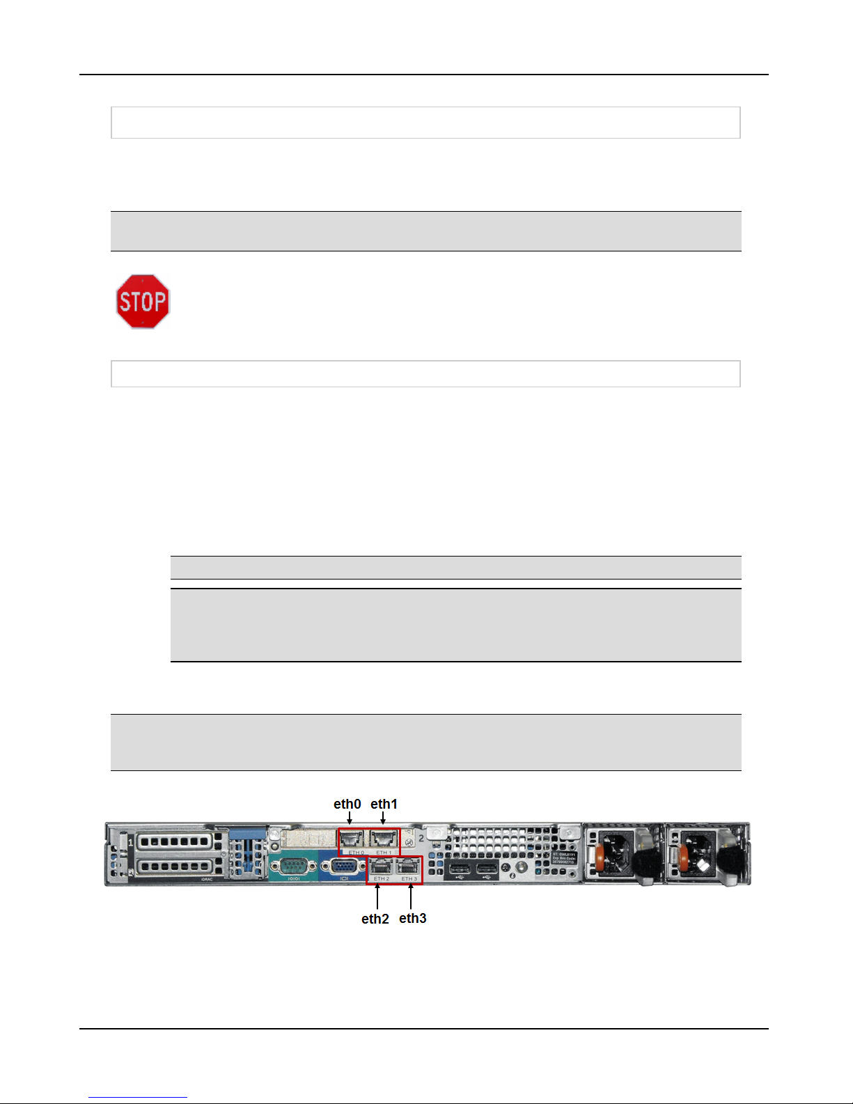
1. See Figures 1 through 7. Note that the port etched with number 1 is eth0 and the port
etched with number 2 is eth1 or the left most port is eth0 and the next port to the right is
eth1.
2. Use either a straight-through or crossover RJ45 cable to connect your PC to eth1 of the
appliance. Port eth1 serves DHCP in the 192.168.1.x range. The appliance itself has an
IP address of 192.168.1.1. Be certain to connect the RJ45 cable to the correct Ethernet
port. LED 1 on the front of the appliance lights to indicate when eth0 has established
connection. LED 2 lights to indicate when eth1 has established connection.
Note: Not all models of the appliance have LED lights on the front .
Note: When a FortiNac Control Server and Application Server are paired, configure the
FortiN ac Application Server hardware f irst to assign an IP address. The FortiNac
Control Server must know the IP address of the FortiNac Application Server in order to
communicate w ith it.
3. On the PC, bring up a web browser. To launch the Configuration Wizard, navigate to:
http://192.168.1.1:8080/configWizard
Note: Appliances have a LCD panel on the front that dis plays the Applianc e Type, such as
FortiN ac Cont rol Server, and the FortiNac Version number installed. This information does not
display until the FortiNac software is started.
Figure 1: Appliance BFN320
6
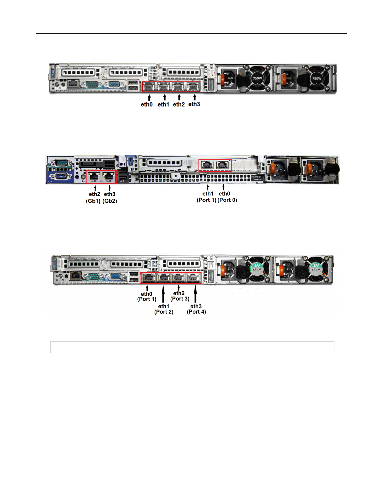
Figure 2: Appliance BFN620 and BFN620XL
Hardware Setup
Figure 3: Appliance BFN330
Figure 4: Appliance BFN630 and BFN630XL
Login To Configuration Wizard - Hardware Setup
1. If you have not done so already, bring up a web browser and navigate to:
http://192.168.1.1:8080/configWizard
2. Enter the User Name and Password credentials to gain access to the Configuration
Wizard.
User Name = config
Password = config
3. Click OK.
7

Hardware Setup
Note: You will be required to change the Configuration Wizard pass word during the
setup proces s.
8
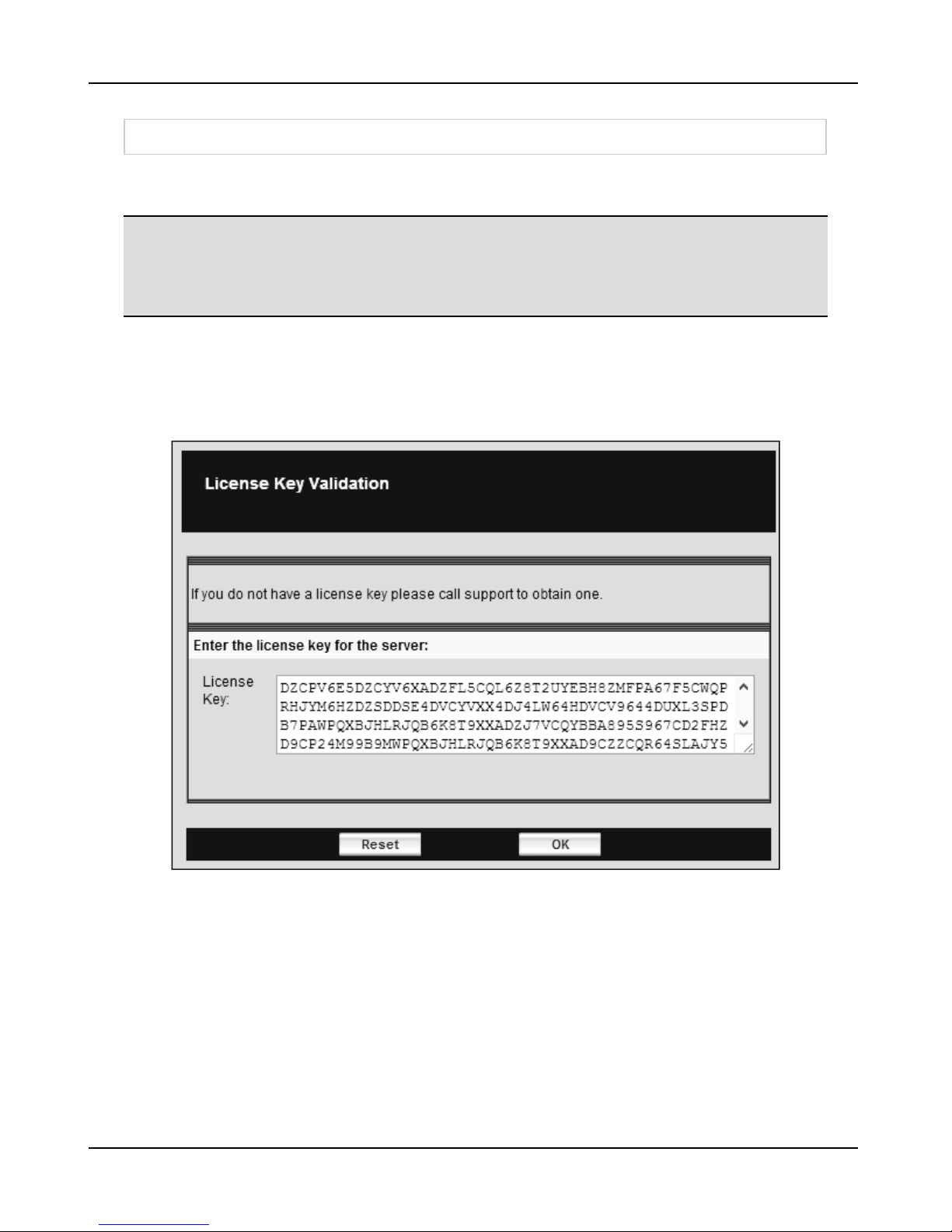
Verify License Key
Verify License Key
Each appliance requires a unique License Key to run the application. The License Key contains
the license count, license time, feature set, and high availability options.
Note: When the License Key Validation window opens, if you do not see a license k ey, contact
Customer Support or your sales represent ativ e to obtain it. For cus tomer identification, have the
MAC Address of the applianc e ready w hen you call for assistance. The MAC Addres s is located
on the s hipping label, the A ppliance Identification Details document and on the back or the top
of the met al casing of the appliance.
1. If a license key appears in the text area, click OK. If there is no key, contact Customer
Support or your sales representative.
2. On the next screen you can download PDF versions of the documentation to your PC
and then click OK to continue.
Figure 5: License Key Validation Window
9
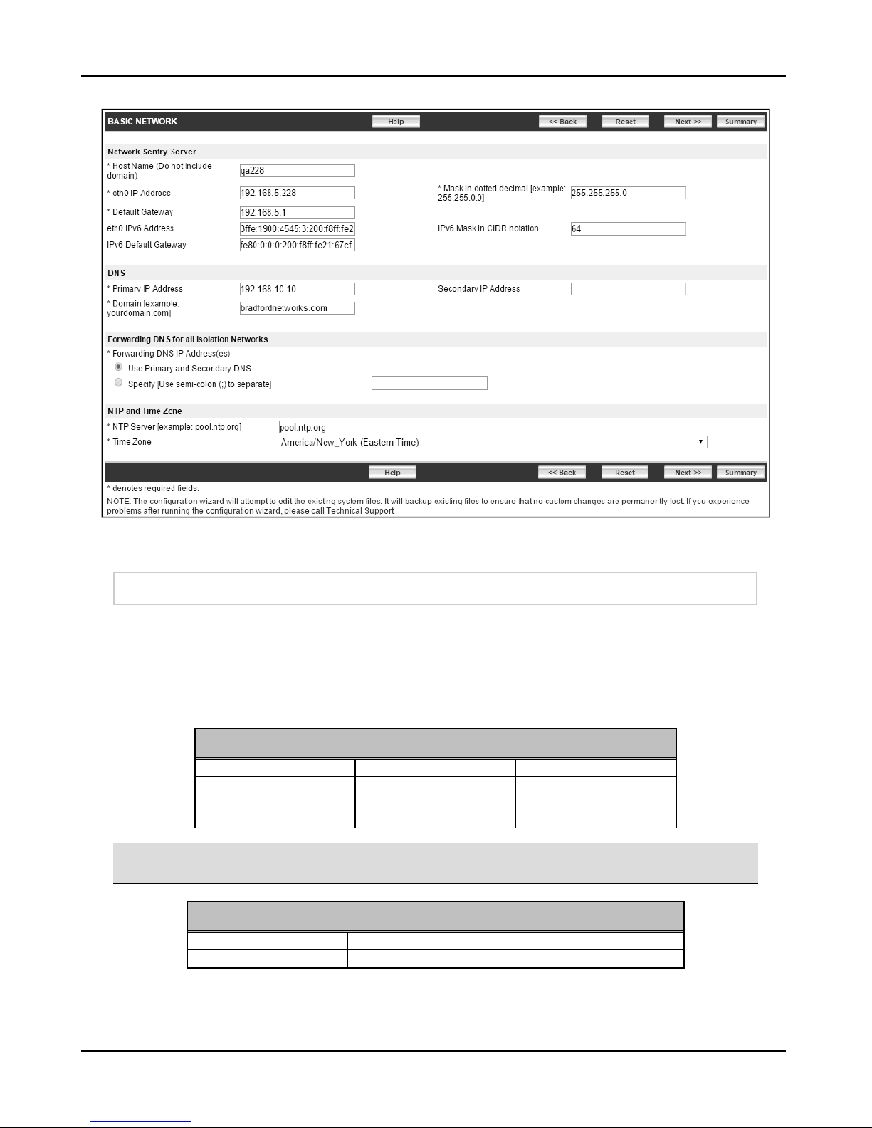
Assign IP Address
Assign IP Address
The initial Basic Network screen displays the Product Descriptor and the type of system you are
configuring. See Naming Conventions on page 1.
1. Configure the FortiNac appliance and enter the values based on the definitions in Basic
Network Window Field Definitions below.
WARNING: Do not use the f ollowing as the Host Name for the appliance: nac,
isolation, registrat ion, remediation, remotereg, remotescan, vpn, authentication, hub,
access point management, or deadend. These names are reserved for s ystem us e.
WARNING: Host names s hould c ontain only letters, numbers or hyphens (-).
Uppercase letters are conv erted to lowercase automatically.
2. Click Apply.
3. Review the information in the Results page. If there are errors or omissions, click Back
on the browser. Make the changes and reapply them.
4. Reboot or shut down the appliance. The DHCP service accessed via eth1 during
installation is disabled.
Note: The data displayed in the Configuration Wizard may not represent the current
configuration of the appliance. When you make edits in the Configuration Wizard, your
modifications are stored in a temporary file. This allows you to exit the Conf iguration
Wizard before you save y our changes permanently.
Table 9: Basic Network Window Field Definitions
Field Definition
FortiNac Product
Host Name
eth0 IP Address
Default Gateway
eth0 IPv6 Address
Name of the appliance you are configuring. Host names should contain only
letters, numbers or hyphens (-). Uppercase letters are converted to lowercase
automatically.
Note: Do not use nac, isolation, regist ration, remediation,
remotereg, remotescan, vpn, authentication, hub, or deadend.
These names are reserved for sys tem use.
Management IPv4 address of the appliance you are configuring.
Default Gateway IPv4 address for the appliance you are configuring. A
default gateway is the device that passes traffic from the local subnet to
devices on other subnets.
Management of IPv6 address of the appliance you are configuring.
IPv6 Default Gateway
10
Default Gateway IPv6 address for the appliance you are configuring. A
default gateway is the device that passes traffic from the local subnet to
devices on other subnets.
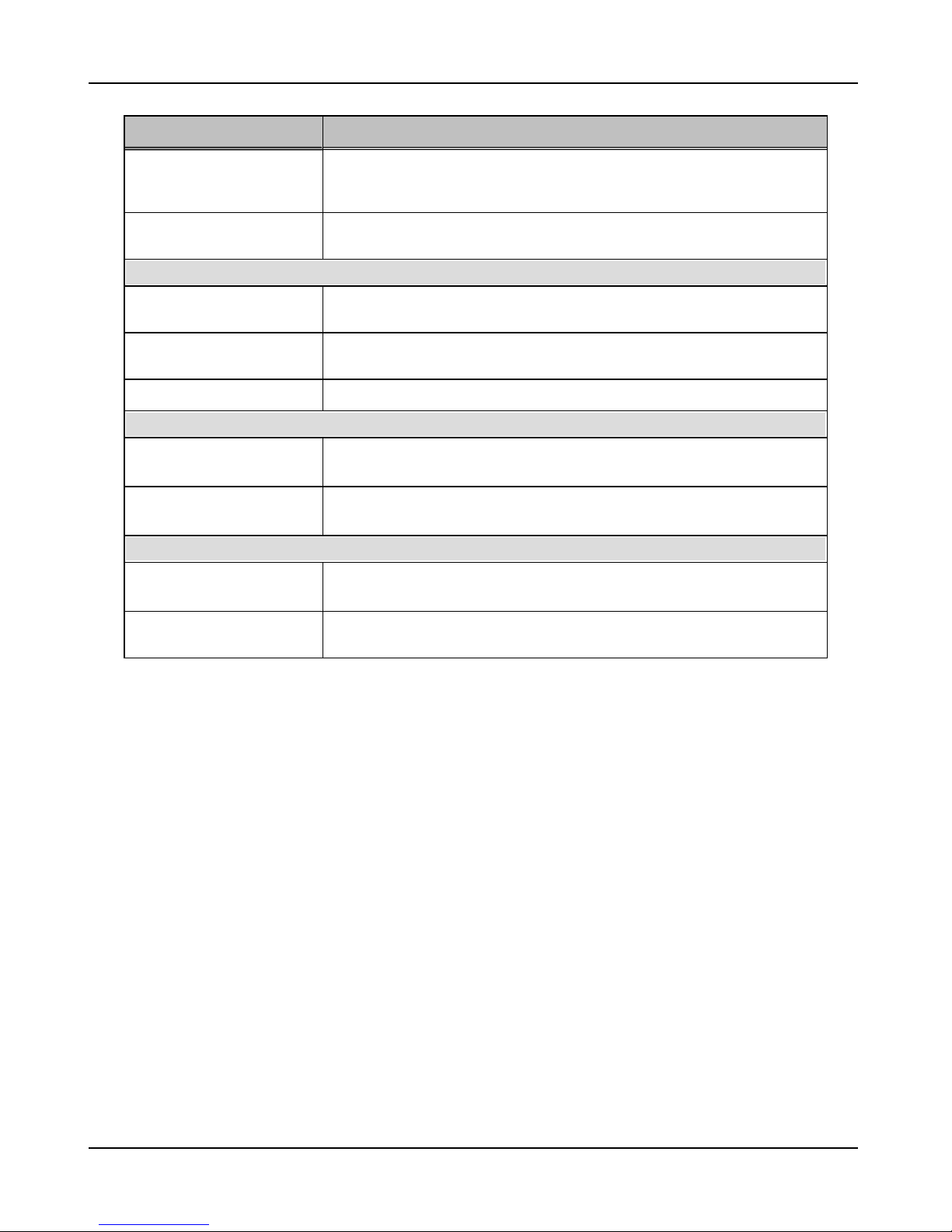
Field Definition
Subnet IPv4 mask for the appliance you are configuring. A subnet is a logical
Mask
grouping of connected network devices; the mask defines the boundaries of
the subnet.
Assign IP Address
IPv6 Mask in CIDR notation
Subnet IPv6 mask for the appliance you are configuring, in CIDR format (e.g.,
64).
DNS
Primary IP Address
IP address of the Primary DNS Server. This is used in the basic IP network
configuration for the appliance.
Secondary IP Address
Domain
IP address of the Secondary DNS Server. This is used in the basic IP network
configuration for the appliance.
Enter your domain name, such as megatech.com or megatech.edu.
Forwarding DNS for all Isolation Networks
Use Primary and
Select this option to use the Primary and Secondary DNS IP addresses.
Secondary DNS
Specify [Use semi-colon (;)
to separate]
Select this option to specify a different DNS IP address, and enter the
address(es).
NTP and Time Zone
NTP Server [example:
pool.ntp.org]
Time Zone
The address of the NTP(Network Time Protocol) server used to keep system
clocks up-to-date with official time.
Specify which timezone where the system is located to show the correct time
for your timezone.
11
Configuration Wizard - Passwords
Figure 6: Basic Network - Assign IP Address
Configuration Wizard - Passwords
Password fields appear empty until you modify a password. Passwords can be modified again
later by accessing the Change Passwords screen. See Change Passwords After Configuration
on page 45.
CLI/SSH and Configuration Wizard passwords must be eight characters or longer and contain a
lowercase letter, an uppercase letter, a number, and one of the following symbols:
Required Symbols
! exclamation point @ at _ underscore
# pound $ dollar ~ tilde
% percent ^ caret - hyphen
* asterisk ? question mark
Note: The sy mbols listed below are not permitted in CLI/SSH and Configuration Wizard
passw ords.
Prohibited Symbols
( open parenthesis space { open curly bracket
) close parenthesis ; semicolon } close curly bracket
12
 Loading...