

Page 1
FortiGate-7060E System Guide
7000
Page 2

FORTINET DOCUMENTLIBRARY
http://docs.fortinet.com
FORTINETVIDEOGUIDE
http://video.fortinet.com
FORTINETBLOG
https://blog.fortinet.com
CUSTOMERSERVICE&SUPPORT
https://support.fortinet.com
http://cookbook.fortinet.com/how-to-work-with-fortinet-support/
FORTIGATECOOKBOOK
http://cookbook.fortinet.com
FORTINETTRAININGSERVICES
http://www.fortinet.com/training
FORTIGUARDCENTER
http://www.fortiguard.com
FORTICAST
http://forticast.fortinet.com
ENDUSER LICENSE AGREEMENT
http://www.fortinet.com/doc/legal/EULA.pdf
FORTINET PRIVACY POLICY
https://www.fortinet.com/corporate/about-us/privacy.html
FEEDBACK
Email: techdocs@fortinet.com
Monday, March 26, 2018
FortiGate-7060E System Guide
01-540-411632-20180326
Page 3

TABLEOFCONTENTS
FortiGate-7060E Chassis 5
FortiGate-7060E front panel 5
FIM modules 6
FPM-7620E FPMmodules 6
FortiGate-7060E back panel 7
Registering your FortiGate-7060E chassis 7
FortiGate-7060E chassis schematic 8
Chassis hardware information 9
Shipping components 9
Optional accessories and replacement parts 9
Physical description of the FortiGate-7060E chassis 10
Cooling fans, cooling air flow, and minimum clearance 11
Cooling air flow and required minimum air flow clearance 12
Optional air filters 13
AC Power Supply Units (PSUs) and supplying AC power to the chassis 13
Hot Swapping an AC PSU 13
DC Power Supply Units (PSUs) and supplying DC power to the chassis 14
Crimping guidelines 15
Connecting a FortiGate-7060E PSU to DC power 16
Hot Swapping a DC PSU 17
Connecting the FortiGate-7060E chassis to ground 17
Turning on FortiGate-7060E chassis power 18
FortiGate-7060E hardware assembly and rack mounting 19
Installing accessories 20
Mounting the FortiGate-7060E chassis in a four-post rack 21
Mounting the FortiGate-7060E chassis in a two-post rack 22
Air flow 22
Inserting FIM and FPM-7000 series modules 23
Recommended slot locations for interface modules 23
FortiGate-7060E Management Modules 24
Management module failure 25
Management Module LEDs 25
About management module alarm levels 28
Using the console ports 28
Page 4

Connecting to the FortiOS CLI of the FIM module in slot 1 29
Connecting to the FortiOS CLI of the FIM module in slot 2 30
Connecting to the SMC SDI CLI of the FPMmodule in slot 3 30
Changing the management module admin account password 30
Connecting to the management module using an IPMItool 31
FortiGate-7060E chassis slots IPMB addresses 31
Rebooting a chassis module from the SMC SDI CLI 32
Comlog 32
System event log (SEL) 34
Sensor data record (SDR) 34
Common management module CLI operations 35
Cautions and Warnings 39
Environmental Specifications 39
Safety 40
Regulatory Notices 42
Federal Communication Commission (FCC) – USA 42
Industry Canada Equipment Standard for Digital Equipment (ICES) – Canada 42
European Conformity (CE) - EU 42
Voluntary Control Council for Interference (VCCI) – Japan 43
Product Safety Electrical Appliance & Material (PSE) – Japan 43
Bureau of Standards Metrology and Inspection (BSMI) – Taiwan 43
China 43
Page 5
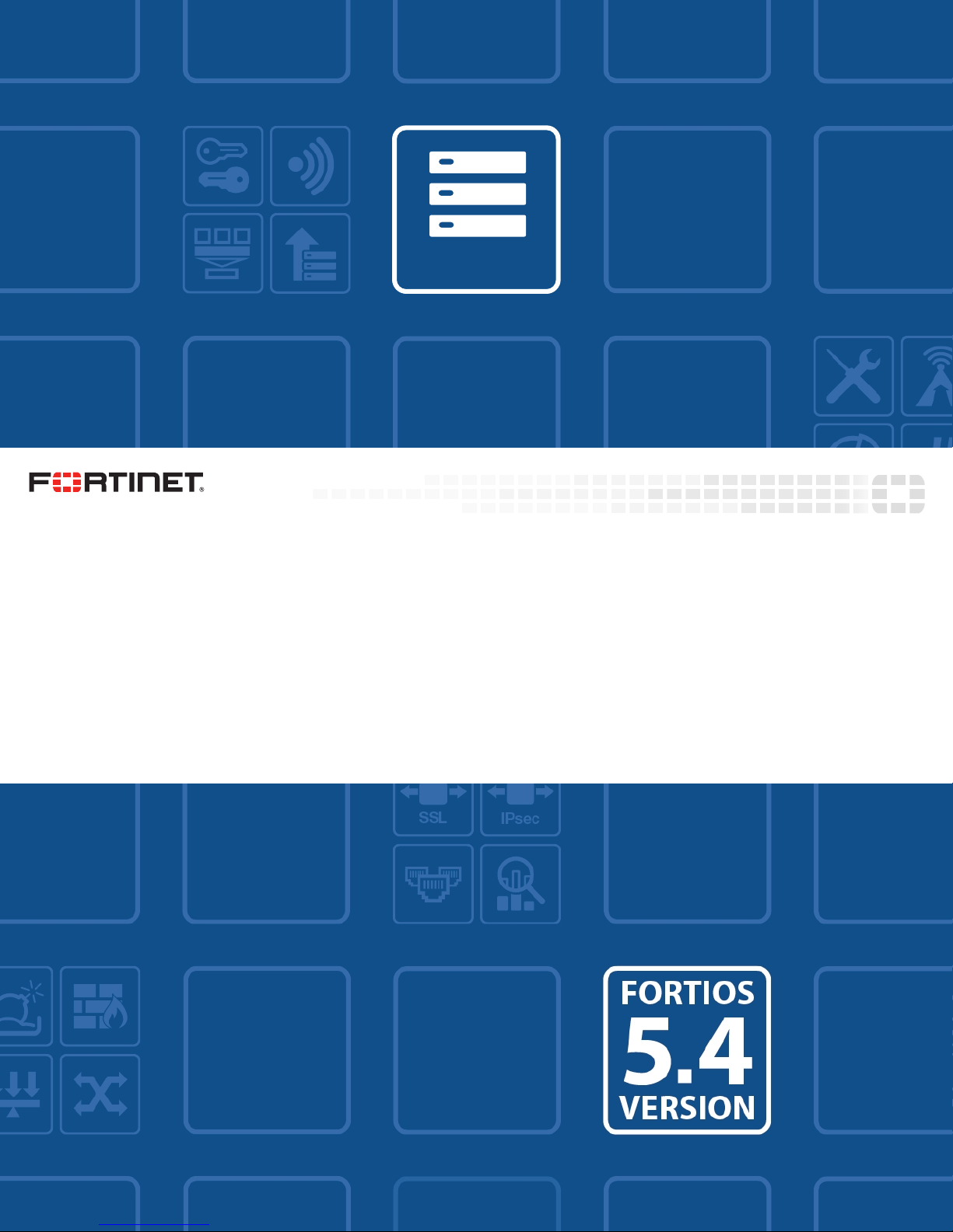
FortiGate-7060E front panel FortiGate-7060E Chassis
ESD
socket
FPM-7620E
slot 3
FPM-7620E
slot 4
FIM-7910E
slots 1 and 2
FPM-7620E
slot 5
FPM-7620E
slot 6
Management Module 2Management Module 1
Power
Supply 6
(empty)
Power
Supply 5
(empty)
Power
Supply 1
Power
Supply 4
Power
Supply 2
Power
Supply 3
FortiGate-7060E Chassis
The FortiGate-7060E is a 8U 19-inch rackmount 6-slot chassis with a 80Gbps fabric and 1Gbps base backplane
designed by Fortinet. The fabric backplane provides network data communication and the base backplane
provides management and synch communication among the chassis slots.
FortiGate-7060E front panel
The chassis is managed by two redundant management modules. Each module includes an Ethernet connection
as well as two switchable console ports that provide console connections to the modules in the chassis slots. The
active management module controls chassis cooling and power management and provides an interface for
managing the modules installed in the chassis.
FortiGate-7060E front panel, (showing AC PSUs, example module configuration)
5 FortiGate-7060E System Guide
Fortinet Technologies Inc.
Page 6

FortiGate-7060E Chassis FortiGate-7060E front panel
Do not operate the FortiGate-7060E chassis with open slots on the front or back panel.
For optimum cooling performance and safety, each chassis slot must contain an FIM
or FPM module or an FIM or FPM blank panel (also called a dummy card). For the
same reason, all cooling fan trays, power supplies or power supply slot covers must be
installed while the chassis is operating.
Power is provided to the chassis using four hot swappable 3+1 redundant 100-240 VAC, 50-60 Hz AC or -48V DC
power supply units (PSUs). At least three PSUs (power supplies 1 to 3) must be connected to power. Power
supply 4 is a backup power supply. You can add a 5th or 6th power supply for 3+2 and 3+3 redundancy.
The standard configuration of the FortiGate-7060E includes two FIM (interface) modules in chassis slots 1 and 2
and up to four FPM (processing) modules in chassis slots 3 to 6.
FIM modules
FIM modules are hot swappable interface modules that provide data and management interfaces, base
backplane switching and fabric backplane session-aware load balancing for the chassis. The FIM modules
include an integrated switch fabric and DP2 processors to load balance millions of data sessions over the chassis
fabric backplane to FPM processor modules. The following FIM modules are available:
l The FIM-7901E includes thirty-two front panel 10GigE SFP+ fabric channel interfaces (A1 to A32). These interfaces
are connected to 10Gbps networks. These interfaces can also be configured to operate as Gigabit Ethernet
interfaces using SFP transceivers.
l The FIM-7904E includes eight front panel 40GigE QSFP+ fabric channel interfaces (B1 to B8). These interfaces are
connected to 40Gbps networks. Using 40GBASE-SR4 multimode QSFP+ transceivers, each QSFP+ interface can
also be split into four 10GBASE-SR interfaces and connected to 10Gbps networks.
l The FIM-7910E (shown in FIM modules on page 6) includes four front panel 100GigE CFP2 fabric channel
interfaces (C1 to C4). These interfaces can be connected to 100Gbps networks. Using 100GBASE-SR10 multimode
CFP2 transceivers, each CFP2 interface can also be split into ten 10GBASE-SR interfaces and connected to
10Gbps networks.
l The FIM-7920E includes four front panel 100GigE QSFP28 fabric channel interfaces (C1 to C4). These interfaces
can be connected to 100Gbps networks. Using a 100GBASE-SR4 QSFP28 or 40GBASE-SR4 QSFP+ transceiver,
each QSFP28 interface can also be split into four 10GBASE-SR interfaces and connected to 10Gbps networks.
If you are installing different FIM modules in the FortiGate-7060E chassis, for optimal
configuration you should install the module with the lower model number in slot 1 and
the module with the higher number in slot 2. For example, if your chassis includes a
FIM-7901E and a FIM-7904E, install the FIM-7901E in chassis slot 1 and the FIM7904E in chassis slot 2. Also, for example, if your chassis includes a FIM-7904E and a
FIM-7920E, install the FIM-7904E in chassis slot 1 and the FIM-7920E in chassis slot
2. This applies to any combination of two different interface modules.
FPM-7620E FPMmodules
The FPM-7620E modules are hot swappable processor modules that provide FortiOS firewalling and security
services. The FPM modules function as workers, processing sessions load balanced to them by the FIM modules.
FPM modules include multiple NP6 network processors and CP9 content processors to accelerate traffic.
FortiGate-7060E System Guide
Fortinet Technologies Inc.
6
Page 7
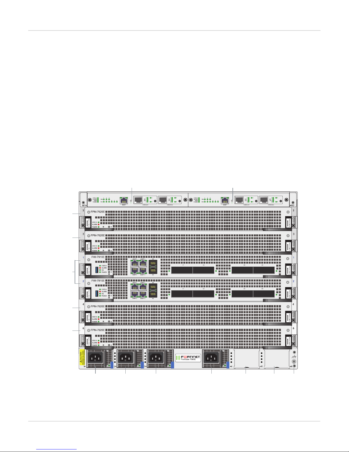
FortiGate-7060E back panel FortiGate-7060E Chassis
Fan Tray 1Fan Tray 2Fan Tray 3
Chassis
Ground
Connector
FortiGate-7060E back panel
The FortiGate-7060E back panel provides access to three hot swappable cooling fan trays and the chassis ground
connector that must be connected to ground.
FortiGate-7060E back panel
Registering your FortiGate-7060E chassis
FortiGate-7000 series products are registered according to the chassis serial number. You need to register your
chassis to receive Fortinet customer services such as product updates and customer support. You must also
register your product for FortiGuard services. Register your product by visiting https://support.fortinet.com. To
7 FortiGate-7060E System Guide
Fortinet Technologies Inc.
Page 8
FortiGate-7060E Chassis FortiGate-7060E chassis schematic
IPMB
SERIAL
IPMB
SERIAL
IPMB
SERIAL
IPMB
SERIAL
NP6
CP9
NP6
CP9
SMC SDI
ISF
DP2
ISF
DP2
IPMB
SERIAL
1G
SMC SDISMC SDI
MGMT2 (active by default, IPMB 0x20)MGMT1 (inactive by default, IPMB 0x22)
FPM Module
FIM Module
FIM Module
FPM Module
FPM3 IPMB 0x86
IPMB
SERIAL
NP6
CP9
SMC SDI
FPM Module
FPM5 IPMB 0x8A
FPM4 IPMB 0x88
FIM1 IPMB 0x82
FIM2 IPMB 0x84
PMB 0x82
SMC SDI
PMB 0x84
SMC SDI
PMB 0x88
SMC SDI
IPMB
SERIAL
NP6
CP9
FPM Module
FPM6 IPMB 0x8C
SMC SDI
Data
Interfaces
MGMT
1-4
M1 M2
Data
Interfaces
MGMT
1-4
M1 M2
Fabric Backplane
1G
1G
1G
1G
1G
1G
80G
80G
80G
80G
80G
80G
80G
80G
80G
80G
80G
80G
80G
80G
80G
80G
40G
40G
Base Backplane
register, enter your contact information and the serial numbers of the Fortinet products that you or your
organization have purchased.
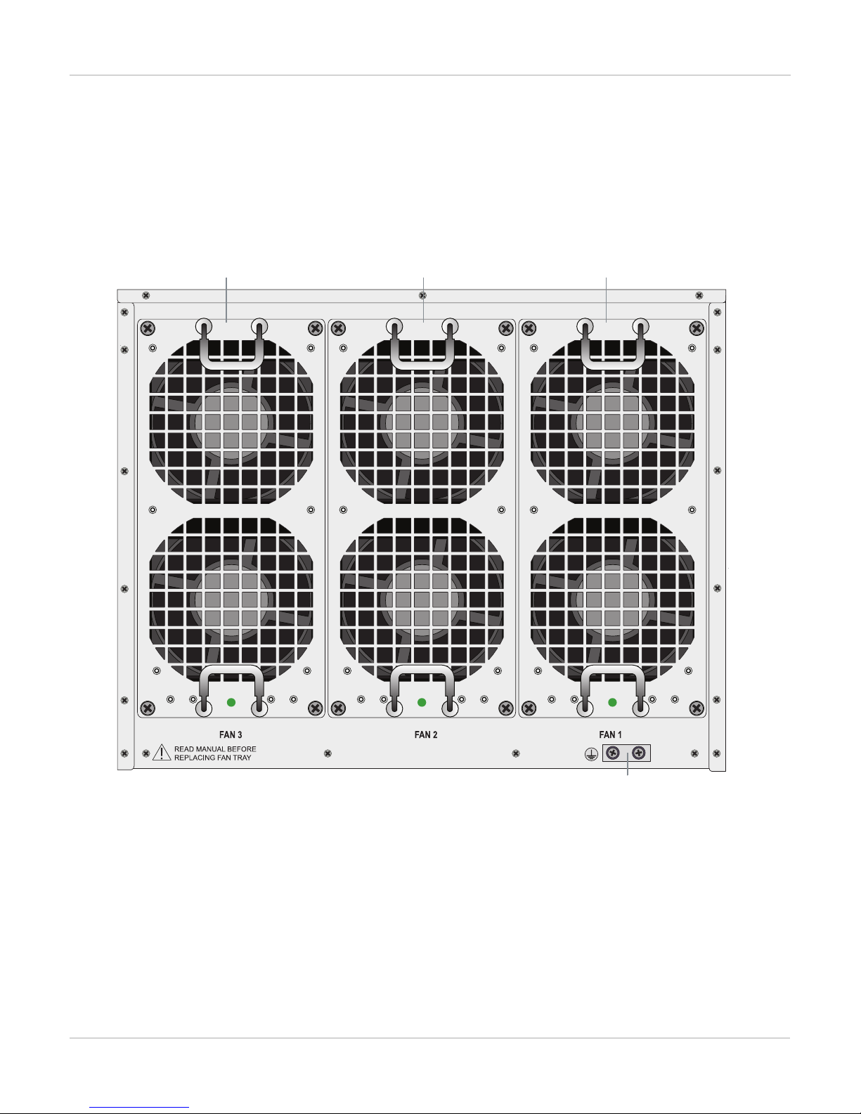
FortiGate-7060E chassis schematic
The FortiGate-7060E chassis schematic below shows the communication channels between chassis components
including the management modules (MGMT), the FIM modules (called FIM1 and FIM2) and the FPM modules
(FPM3, FPM4, FPM5, and FPM6).
By default MGMT2 is the active management module and MGMT1 is inactive. The active management module
always has the IPMB address 0x20 and the inactive management module always has the IPMB address 0x22.
The active management module communicates with all modules in the chassis over the base backplane. Each
module, including the management modules has a Shelf Management Controller (SMC). These SMCs support
Intelligent Platform Management Bus (IPMB) communication between the active management module and the
FIM and FPM modules for storing and sharing sensor data that the management module uses to control chassis
cooling and power distribution. The base backplane also supports serial communications to allow console access
from the management module to all modules, and 1Gbps Ethernet communication for management and
heartbeat communication betweenmodules.
FortiGate-7060E System Guide
Fortinet Technologies Inc.
FIM1 and FIM2 (IPMB addresses 0x82 and 0x84) are the FIM modules in slots 1 and 2. The interfaces of these
modules connect the chassis to data networks and can be used for Ethernet management access to chassis
components. The FIM modules include DP2 processors that distribute sessions over the Integrated Switch Fabric
(ISF) to the NP6 processors in the FPMmodules. Data sessions are communicated to the FPM modules over the
80Gbps chassis fabric backplane.
8
Page 9

Chassis hardware information FortiGate-7060E Chassis
FPM03, FPM04, FPM05, and FPM06 (IPMB addresses 0x86, 0x88, 0x8A, and 0x8C) are the FPM processor
modules in slots 3 to 6. These worker modules process sessions distributed to them by the FIMmodules.
FPMmodules include NP6 processors to offload sessions from the FPM CPU and CP9 processors that accelerate
content processing.
Chassis hardware information
This section introduces FortiGate-7060E hardware components and accessories including power requirements
and FIMand FPM modules that can be installed in the chassis.
Shipping components
The FortiGate-7060E chassis ships pre-assembled with the following components:
l The 8U FortiGate-7060E chassis
l Two FIM modules
l Up to four FPM modules
l Two management modules in the front of the chassis. (Management modules are not field replacable. If a
management module fails you must RMA the chassis. The chassis will continue to operate with one or no operating
management modules.)
l Four Power Supply Units (PSUs) installed in the front of the chassis
l Three cooling fan trays installed in the back of the chassis
l One protective front panel installed in the chassis to protect internal chassis components. This panel must be
removed before installing FIM and FPM modules.
l Four power cords with C15 power connectors
l Four power cord management clamps
l One set of 4-post rack mounting components
l One set of 2-post rack mounting components
l One pair of cable management side brackets
l Two front mounting brackets
l Twenty M4x6 flat-head screws
l Six M4x8 large head pan-head screws
l Six rubber feet
l Two console cables
l One RJ-45 Ethernet cable
Optional accessories and replacement parts
The following optional accessories can be ordered separately:
SKU Description
FG-7060E-FAN FortiGate-7060E fan tray.
9 FortiGate-7060E System Guide
Fortinet Technologies Inc.
Page 10

FortiGate-7060E Chassis Chassis hardware information
SKU Description
FG-7060E-PS-AC 1500W AC power supply units (PSUs) for the FortiGate-7060E.
FG-7060E-PS-DC 1500W DC power supply units (PSUs) for the FortiGate-7060E.
FG-7060E-CHASSIS
FortiGate-7060E chassis including 2x management module, 3x fan trays, and 4x AC or
DC PSUs.
You can also order the following:
l Additional FIM and FPM modules
l Transceivers
l DC PSUs
l Air Filter kit
l FPM and FIM single slot cover trays to be installed in empty chassis slots
The following optional accessories can be ordered separately:
l Additional FIM and FPM modules
l Transceivers
l DC PSUs
l Additional AC PSUs
l Additional FAN trays
l Air Filter kit
l FPM and FIM blank panels to be installed in empty chassis slots
Physical description of the FortiGate-7060E chassis
The FortiGate-7060E chassis is a 8U chassis that can be installed in a standard 19-inch rack. The following table
describes the physical characteristics of the FortiGate-7060E chassis.
Dimensions (H x W x D) 14.0 x 17.3 x 25.6 in (352.7 x 440 x 650 mm)
Chassis weight completely assembled with
FIM and FPM modules installed
207.2 lbs (94.1 kg)
Operating Temperature 32 to 104°F (0 to 40°C)
Storage Temperature -31 to 158°F (-35 to 70°C)
Relative Humidity 10% to 90% non-condensing
Noise Level
63db
AC Input Current and Voltage Range 10-12 A, 100 to 240 VAC (50 to 60 Hz)
DC Input Rating Average: 12.5A@48V for eachPSU, max 44A
FortiGate-7060E System Guide
Fortinet Technologies Inc.
10
Page 11
Cooling fans, cooling air flow, and minimum clearance FortiGate-7060E Chassis
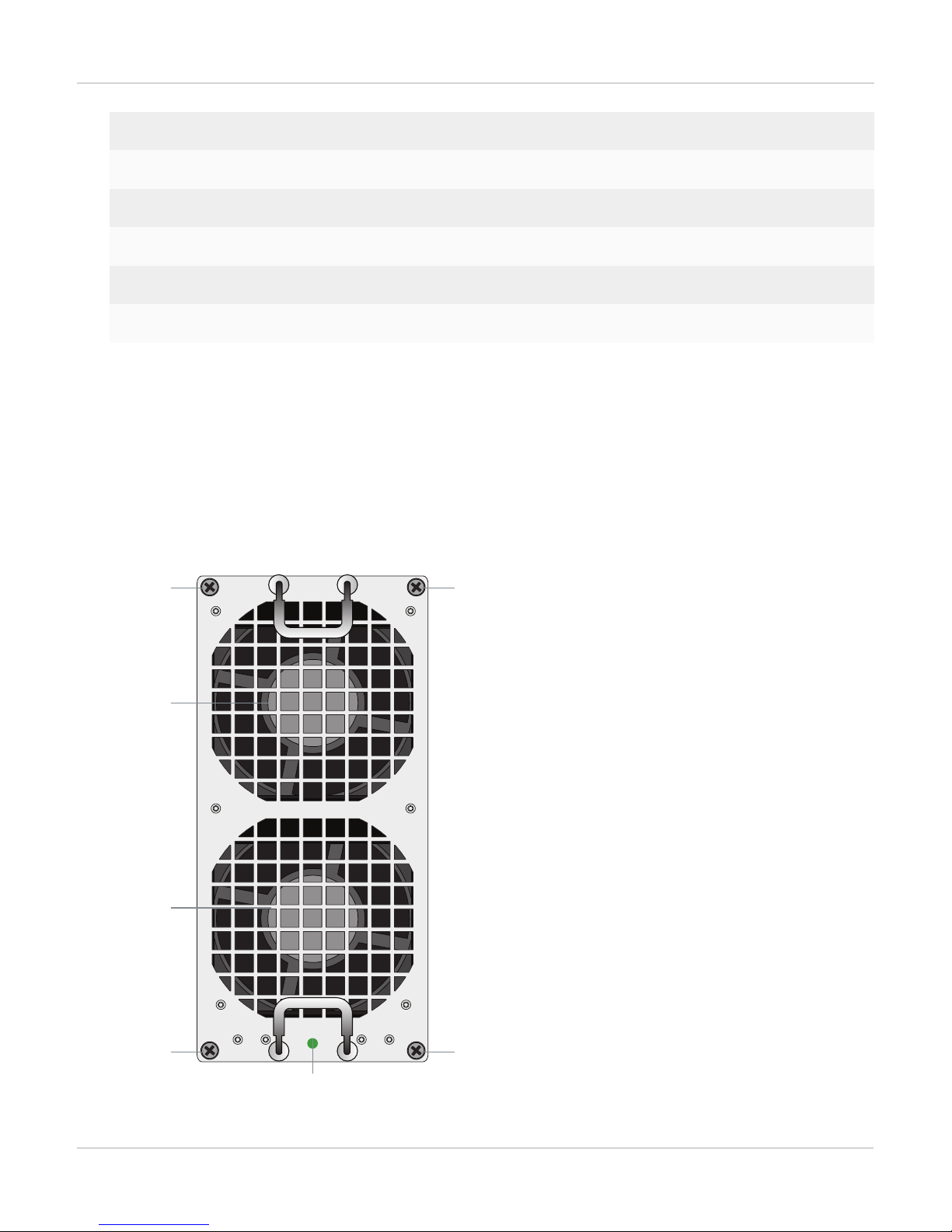
Reten ti on
Screw
Fan
LED
Reten ti on
Screw
Reten ti on
Screw
Reten ti on
Screw
Outle t
Grill
Outle t
Grill
Power Support Rating max. 3277W
Supplied Power Supply Units (PSUs) 4 (for 3+1 redundancy)
Max Power Supply Units (PSUs) 6 (for 3+3 redundancy)
Max Power Consumption 3277W
Average Power Consumption 2330W
Heat Dissipation 11799KJ/hr (11184BTU/hr)
Cooling fans, cooling air flow, and minimum clearance
The FortiGate-7060E chassis contains three hot swappable cooling fan trays installed in the back of the chassis.
Each fan tray includes two fans that operate together. When the fan tray LED is green both fans are operating
normally. If the LED turns red or goes off, one or both of the fans is not working and the fan tray should be
replaced.
Cooling Fan Tray
11 FortiGate-7060E System Guide
Fortinet Technologies Inc.
Page 12
FortiGate-7060E Chassis Cooling fans, cooling air flow, and minimum clearance
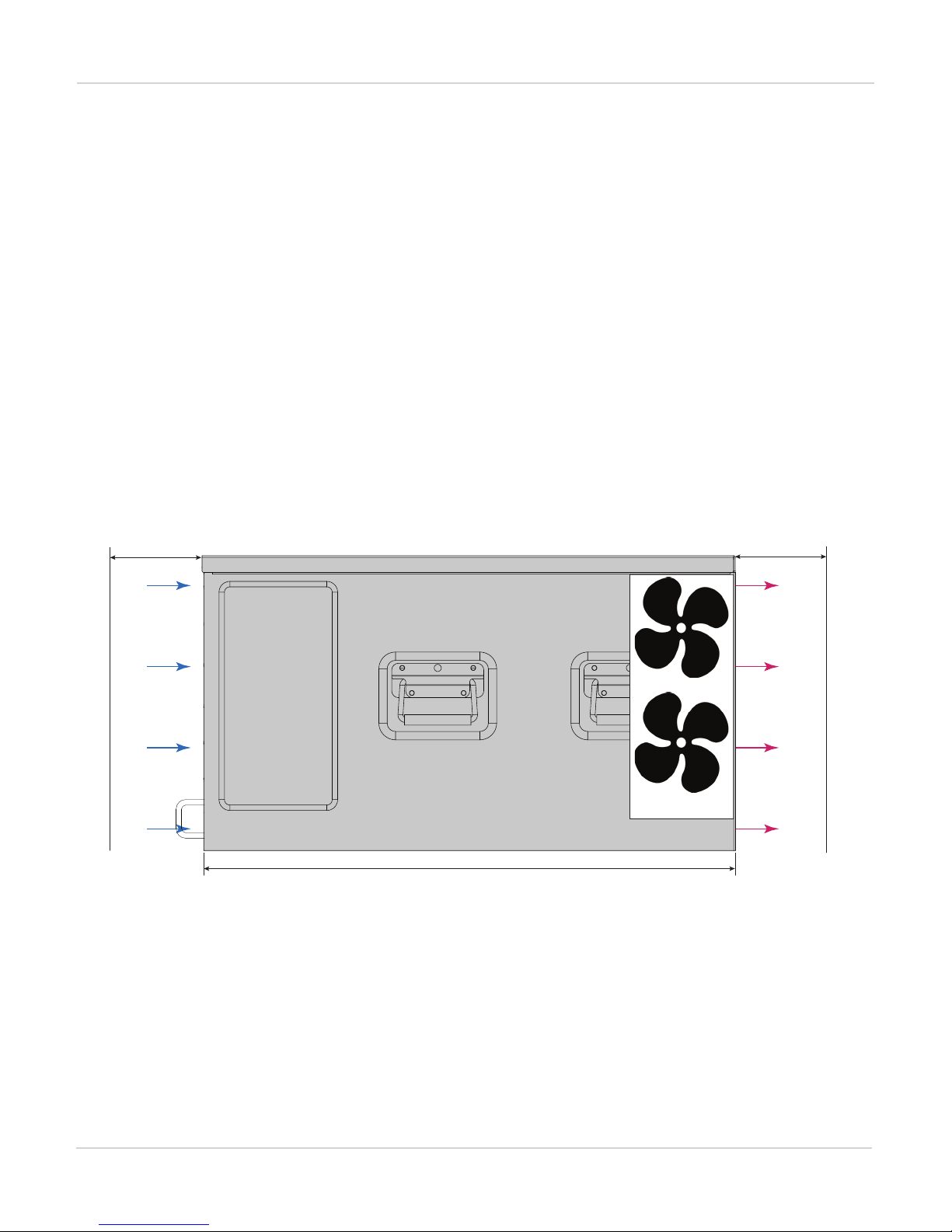
Cool air
Intake
Left and R ig ht
Side Coo l A ir
Intakes
50 mm
Clearanc e
(Optiona l)
Front
FortiGat e- 70 60E chassis ( si de Vie w)
Fan
Trays
100 m m
650 m m
Warm Air
Exhaust
Back
100 m m
During normal chassis operation, all three fan trays are active and the fan speed is controlled by the active
management module. Fan trays are hot swappable. You can replace a failed fan tray while the chassis is
operating. To replace a fan tray, unscrew the four retention screws and use the handles to pull the fan tray out of
the chassis.
Install a replacement fan tray by sliding it into place in the empty slot and tightening the retention screws. As you
slide the new fan into place it will power up and the fan tray LED will light.
The other fan trays will continue to operate and cool the chassis as a fan tray is being removed and replaced.
However an open fan tray slot will result in less air flow through the chassis so do not delay installing the
replacement fan tray.
Cooling air flow and required minimum air flow clearance
When installing the chassis, make sure there is enough clearance for effective cooling air flow. The following
diagram shows the cooling air flow through the chassis and the locations of fan trays. Make sure the cooling air
intake and warm air exhaust openings are not blocked by cables or rack construction because this could result in
cooling performance reduction and possible overheating and component damage.
FortiGate-7060E cooling air flow and minimum air flow clearance
Most cool air enters the chassis through the chassis front panel and all warm air exhausts out the back. For
optimal cooling allow 100 mm of clearance at the front and back of the chassis and 50 mm of clearance at the
sides. Under these conditions 80% of cooling air comes from the front panel air intake and 20% from the left and
right side panels and 100% exits out the back. Side clearance is optional and chassis cooling will be sufficient if
no side clearance is available.
FortiGate-7060E System Guide
Fortinet Technologies Inc.
12
Page 13
Optional air filters FortiGate-7060E Chassis
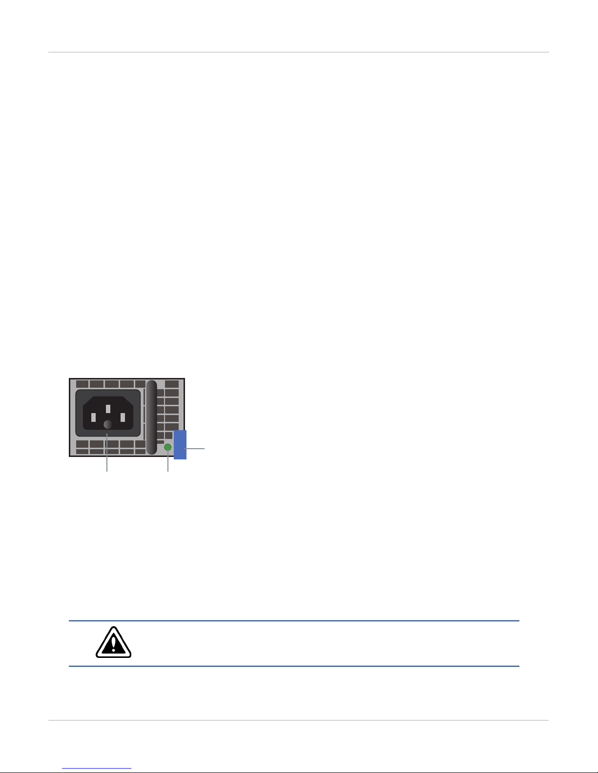
Latch
PSU
LED
C16
Power
Connect or
Optional air filters
You can purchase an optional NEBScompliant air filter kit that includes a front filter that fits over the front of the
chassis and two filters for the side cool air intakes. These filters are not required for normal operation but can be
added if you require air filtration.
The air filters should be inspected regularly. If dirty or damaged, the filters should be disposed of and replaced.
The air filters can be fragile and should be handled carefully.
AC Power Supply Units (PSUs) and supplying AC power to the chassis
The AC version of the FortiGate-7060E chassis front panel includes four hot swappable DC PSUs. At least three
PSUs (1, 2, and 3) must be connected to power. Power supplies 4 to 6 are backup power supplies that provide
3+1 , 3+2, and 3+3 redundancy. See FortiGate-7060E front panel on page 5 for locations of the PSUs.
All PSUs should be connected to AC power. To improve redundancy you can connect each power supply to a
separate power source.
Use a C15 Power cable, supplied with the chassis, to connect power to each PSU C16 power connector. C15/C16
power connectors are used for high temperature environments and are rated up to 120°C.
AC PSU showing C16 power connector
The PSU LED indicates whether the PSUis operating correctly and connected to power. If this LEDis not lit check
to make sure the PSU is connected to power. If the power connection is good then the PSU has failed and should
be replaced.
Hot Swapping an AC PSU
Follow these steps to safely hot swap an AC PSU.
You can hot swap a PSU without powering down the FortiGate-7060E as long as three
PSUs are connected to power and operating normally. If you need to hot swap one of
three operating PSUs you must power down the chassis first.
13 FortiGate-7060E System Guide
Fortinet Technologies Inc.
Page 14

FortiGate-7060E Chassis DC Power Supply Units (PSUs) and supplying DC power to the chassis
1.
Attach an ESD wrist strap to your wrist and to an ESD socket or to a bare metal surface on the chassis or frame.
2.
Turn off the power being supplied to the power supply and disconnect the power cord.
3.
Press the latch towards the handle until the PSU is detached then pull it out of the chassis.
4.
Insert a replacement PSU into the chassis and slide it in until it locks into place.
5.
Connect the PSUpower terminals as described above.
6.
Turn on power to the PSU.
7.
Verify that the PSU status LED is solid green meaning that the PSU is powered up and operating normally.
DC Power Supply Units (PSUs) and supplying DC power to the chassis
The DC version of the FortiGate-7060E chassis front panel comes with four hot swappable 48-72V to 12V 125A
DC PSUs. Each PSU has a Internal 60A/170VDC fast blow fuse on the DC line input.
At least three PSUs (power supplies 1, 2, and 3) must be connected to power. The fourth power supply is a
backup power supply and provides 3+1 redundancy. You can add a 5th power supply to provide a second backup
power supply and 3+2 redundancy. You can add a 6th power supply to provide a third backup power supply and
3+3 redundancy. See FortiGate-7060E front panel on page 5 for locations of the PSUs. The diagram shows AC
PSUs, with a DC version of the chassis the AC PSUs are replaced with DC PSUs.
Each PSU is designed to be installed in a Telecom data center or similar location that has available -48VDC
power fed from a listed 40A circuit breaker. To improve redundancy you can connect each power supply to a
separate power circuit.
DC power cables are intended to be used only for in-rack wiring, must be routed away from sharp edges, and
must be adequately fixed to prevent excessive strain on the wires and terminals.
DC terminals accept UL approved ring terminals for 8/M4 stud with ext ring diameter < 9.8 mm. DC cables must
be a minimum of 8 AWG.
The following table lists some key power data for each PSU.
Max Inrush Current 50A
Max Inrush Current Duration 200ms
Input Voltage -40V to -72V
Input Current Average: 12.5A@48V for each PSU, Max: 44A
FortiGate-7060E System Guide
Fortinet Technologies Inc.
14
Page 15

DC Power Supply Units (PSUs) and supplying DC power to the chassis FortiGate-7060E Chassis
Latch
LED
+ (Red)
Power
Connector
- (Black)
Power
Connector
DC PSU (power connector cover removed)
PSU LED States
State Description
Off DC power not connected.
Flashing
Green
Green Normal Operation with DC power connected.
Amber
Flashing
Amber
The PSUis in standby mode, not supplying power to the chassis.
Input voltage outside of normal operating range, PSU fan not operating, or output voltage outside of
normal operating range.
Warning that power input or output is close to outside of normal operating range. PSU should be
replaced.
Crimping guidelines
To connect the PSUs to data center power you should use 8 AWG or larger wires depending on the wire length
and the power requirements of your chassis. The ends of these wires must be fitted with UL approved ring
terminals for 8/M4 studs with ext ring diameter < 9.8 mm. Use the following information to crimp and prepare
these wires.
Do not crimp energized wires.
Follow these crimping guidelines:
l Strip the insulation from cable. Be careful not to nick cable strands which may later result in stands breaking.
l Cable end should be clean: wire brush or clean with emery cloth if necessary. Insert cable into connector until it
stops. The insertion length must approximate the stripped length of cable.
15 FortiGate-7060E System Guide
Fortinet Technologies Inc.
Page 16

FortiGate-7060E Chassis DC Power Supply Units (PSUs) and supplying DC power to the chassis
DC Power
Source
-48VDC
RTN
+ RTN
(red)
-48VDC
(black)
l Insert connector in die and compress between the markings beginning near the tongue of the connector. Using the
wrong installing die may result in a defective connection.
l After crimping, remove all sharp edges, flash or burrs.
Connecting a FortiGate-7060E PSU to DC power
The following procedure describes how to connect a PSU to DC power. Repeat this procedure to connect each
PSU.
You need the following equipment to connect the primary FortiGate-7060E PSUs to DC power:
l An electrostatic discharge (ESD) preventive wrist strap with connection cord.
l One black 8 AWG stranded wire with attached UL approved ring terminal for 8/M4 studs with ext ring diameter < 9.8
mm.
l One red 8 AWG stranded wire with attached UL approved ring terminal for 8/M4 studs with ext ring diameter < 9.8
mm.
To connect a PSU to DC power
1.
Attach the ESD wrist strap to your wrist and to an ESD socket or to a bare metal surface on the chassis or frame.
2.
Make sure that the PSU and power cords are not energized.
3.
Snap the clear plastic cover off of the PSUpower terminals.
4.
Remove the first set of nuts and lock washers from the connectors on the PSU.
5.
Connect the black -48V power wire from your DC power source to the connector on the PSU labeled - using the
ring terminal.
6.
Connect the red RTN power wire from you RTN power source to the connector on the PSU labeled + using the ring
terminal.
7.
Use the previously removed nuts and lock washers to secure the connectors. Do not apply torque of more than 3.8
Nm (33.62 lbf.in).
8.
Snap the clear plastic cover over the PSU power terminals.
9.
Make sure the power wires are secured using tie wraps if required.
10.
If required, label the black wire -48V.
11.
If required, label the red wire RTN.
12.
Turn on power to the PSU.
13.
Verify that the PSU status LED is solid green meaning that the PSU is powered up and operating normally.
FortiGate-7060E System Guide
Fortinet Technologies Inc.
16
Page 17

Connecting the FortiGate-7060E chassis to ground FortiGate-7060E Chassis
Data Center
ground
connector
(Central office
ground system)
Chassis
Ground
Connector
Hot Swapping a DC PSU
Follow these steps to safely hot swap a DC PSU.
You can hot swap a PSU without powering down the FortiGate-7060E as long as three
PSUs are connected to power and operating normally. If you need to hot swap one of
two operating PSUs you must power down the chassis first.
1.
Attach an ESD wrist strap to your wrist and to an ESD socket or to a bare metal surface on the chassis or frame.
2.
Turn off the power being supplied to the PSU.
3.
Snap off the terminal cover and remove the wires from the PSU terminals.
4.
Press the latch towards the handle until the PSU is detached then pull it out of the chassis.
5.
Insert a replacement PSU into the chassis and slide it in until it locks into place.
6.
Connect the PSUpower terminals as described above.
7.
Turn on power to the PSU.
8.
Verify that the PSU status LED is solid green meaning that the PSU is powered up and operating normally.
Connecting the FortiGate-7060E chassis to ground
The FortiGate-7060E chassis includes a ground terminal on the rear the bottom of the FortiGate-7060E back
panel. The ground terminal provides two connectors to be used with a double-holed lug such as Thomas & Betts
PN 54850BE. This connector must be connected to a local ground connection.
You need the following equipment to connect the FortiGate-7060E chassis to ground:
l An electrostatic discharge (ESD) preventive wrist strap with connection cord.
l One green 6 AWG stranded wire with listed closed loop double-hole lug suitable for minimum 6 AWG copper wire,
such as Thomas & Betts PN 54850BE.
To connect the FortiGate-7060E chassis to ground
1.
Attach the ESD wrist strap to your wrist and to an ESD socket or to a bare metal surface on the chassis or frame.
2.
Make sure that the chassis and ground wire are not energized.
3.
Connect the green ground wire from the local ground to the ground connector on the FortiGate-7060E chassis.
4.
Secure the ground wire to the chassis.
5.
Optionally label the wire GND.
17 FortiGate-7060E System Guide
Fortinet Technologies Inc.
Page 18

FortiGate-7060E Chassis Turning on FortiGate-7060E chassis power
Turning on FortiGate-7060E chassis power
Connect AC or DC power to PSUs 1, 2, 3, and 4. Once the FortiGate-7060E chassis is connected to power the
chassis powers up. If the chassis is operating correctly, the LEDs on the PSUs and fans should be lit. As well, the
LEDs on the FortiGate-7060E management module should be lit.
When the chassis first starts up you should also hear the cooling fans operating.
In addition, if any modules have been installed in the chassis they should power on and their front panel LEDs
should indicate that they are starting up and operating normally.
FortiGate-7060E System Guide
Fortinet Technologies Inc.
18
Page 19

Turning on FortiGate-7060E chassis power FortiGate-7060E hardware assembly and rack mounting
FortiGate-7060E hardware assembly and rack mounting
The FortiGate-7060E chassis must be mounted in a standard 19-inch rack and requires 8Uof vertical space in the
rack. This chapter describes how to attach accessories to the FortiGate-7060E chassis, how to install the chassis
in a 4-post or 2-post rack, and how to install FIM and FPM modules in the chassis front panel slots.
If you install the FortiGate-7060E chassis in a closed or multi-unit rack assembly, the operating ambient
temperature of the rack environment may be greater than room ambient temperature. Make sure the operating
ambient temperature does not exceed the manufacturer's maximum rated ambient temperature.
The FortiGate-7060E chassis should not be operated as a free-standing appliance.
It is recommended that you mount the FortiGate-7060E chassis near the bottom of the rack to avoid making the
rack top-heavy and potentially falling over. If you are going to mount the chassis higher make sure the rack is well
anchored. Since the chassis is over 100 lbs use a lift to raise the chassis into position before mounting it.
Install accessories before mounting the chassis in a rack. Install the modules after the
chassis is rack mounted.
19 FortiGate-7060E System Guide
Fortinet Technologies Inc.
Page 20

FortiGate-7060E hardware assembly and rack mounting Installing accessories
Front Mounting
Brack et
Front Cable
Manag ement
Brack et
Left Cable
Manag ement
Brack et
Right Cable
Manag ement
Brack et
M4x 8 la rge he ad
pan hea d scre ws
M4x 8 la rge he ad
pan hea d scre ws
M4x 8 fl at-hea d
scr ews
M4x 8 fl at-hea d
scr ews
Front Mounting
Brack et
Power Cord
Clamp s
Installing accessories
These accessories are optional and not required for all configurations. If you have them, before mounting the
chassis in a rack you should install the left and right front mounting brackets and the cable management brackets
as shown in the following illustration.
Installing FortiGate-7060E accessories
You can also install power cord clamps into the front of the chassis beside each PSU. Install the clamps by
inserting them into the holes adjacent each supply at the back of the chassis. Use the clamps to secure the AC
power cords so they are not accidentally disconnected.
FortiGate-7060E System Guide
Fortinet Technologies Inc.
20
Page 21

Mounting the FortiGate-7060E chassis in a four-post rack FortiGate-7060E hardware assembly and rack mounting
Secur e the Chassis
to th e Rack Mount Tray
Rac k Mo unt
Scr ews not
pro vide d
M4x 6 pa n-head screw
wit h M4 washe r
Rac k Mo unt
Scr ews not
pro vide d
Attac h the Left
Tray to th e Left
Rack Po sts
Attac h the Right
Tray to th e Right
Rack Po sts
Rac k Mo unt
Scr ews not
pro vide d
Mounting the FortiGate-7060E chassis in a four-post rack
The FortiGate-7060E package includes a set of extendable brackets that you can use to mount the chassis in a 4post rack. Install the brackets to create a 4-post rack mount tray that the chassis will slide on to. Attach each side
of the tray to the 4-post rack using the front and back brackets as shown below. Make sure you install the tray with
enough space above it for the chassis. The length of the tray sides adjusts to match your rack.
Once the 4-post rack mount tray has been installed, slide the chassis onto the tray and secure it to the rack mount
tray as shown in the diagram.
Mounting the chassis in a four-post Rack
21 FortiGate-7060E System Guide
Fortinet Technologies Inc.
Page 22

FortiGate-7060E hardware assembly and rack mounting Mounting the FortiGate-7060E chassis in a two-post rack
Left Mid Mount Tray
(Atta ch to the Rack
First )
M4x 6 fl at hea d
scr ews
M4x 6 fl at hea d
scr ews
Right Mid Moun t Tray
(Atta ch to the Rack Fir st)
Left Mid Mount Ear
(Atta ch to the
Chass is)
Right Mid
Mount Ear
(Atta ch to the
Chass is)
Mounting the FortiGate-7060E chassis in a two-post rack
The FortiGate-7060E package includes two mid-mount trays and two mid-mount ears that you can use to mount
the chassis in a 2-post rack. As shown in the diagram, first attach the mid-mount trays to the rack making sure to
leave enough space above the trays for the chassis. Then attach the mid-mount ears to the chassis also as shown
in the diagram. Finally line up the mid-mount trays with the mid-mount ears so that the chassis is supported in the
rack. Then use screws to attach the mid-mount ears and the chassis to the rack.
Mounting the chassis in a 2-post rack
Air flow
For rack installation, make sure that the amount of air flow required for safe operation of the FortiGate-7060E
chassis is not compromised. Make sure that the chassis ventilation openings at the front and back are not blocked
by cables or other components. The recommended minimum clearance at the front of the chassis is 100 mm and
the recommended clearance from the rear of the chassis is 100 mm. This results in a total footprint of 850 mm
from front to back. See FortiGate-7060E Chassis on page 5 for more details.
FortiGate-7060E System Guide
Fortinet Technologies Inc.
22
Page 23

Inserting FIM and FPM-7000 series modules FortiGate-7060E hardware assembly and rack mounting
Inserting FIM and FPM-7000 series modules
All FortiGate-7060E chassis are shipped with a protective front panel installed in the chassis to protect internal
chassis components. This panel must be removed before you install FIM and FPM modules.
Insert FIM modules into chassis slots 1 and 2. Insert FPM modules into chassis slots 3, 4, 5, and 6.
Do not operate the FortiGate-7060E chassis with open slots on the front or back panel.
For optimum cooling performance and safety, each chassis slot must contain an FIM
or FPM module or an FIM or FPM blank panel (also called a dummy card). For the
same reason, all cooling fan trays, power supplies or power supply slot covers must be
installed while the chassis is operating.
To insert FIM and FPM modules, see the guide supplied with the module.
You must carefully slide the module all the way into the chassis slot, close the handles
to seat the module into the slot, and tighten the retention screws to make sure the
module is fully engaged with the backplane and secured. You must also make sure
that the sliding latches are fully closed by gently pushing them down. The handles
must be closed, the retention screws tightened and the latches fully closed for the
module to get power and start up. If the module is not receiving power all LEDs remain
off.
All FIM and FPM-7000 series modules must be protected from static discharge and
physical shock. Only handle or work with these boards at a static-free workstation.
Always wear a grounded electrostatic discharge (ESD) preventive wrist strap when
handling these boards.
Recommended slot locations for interface modules
If you are installing different FIM modules in the FortiGate-7060E chassis, for optimal configuration you should
install the module with the lower model number in slot 1 and the module with the higher number in slot 2.
For example:
l if your chassis includes a FIM-7901E and a FIM-7904E, install the FIM-7901E in chassis slot 1 and the FIM-7904E
in chassis slot 2.
l If your chassis includes a FIM-7904E and a FIM-7920E, install the FIM-7904E in chassis slot 1 and the FIM-7920E
in chassis slot 2.
This applies to any combination of two different interface modules.
23 FortiGate-7060E System Guide
Fortinet Technologies Inc.
Page 24

FortiGate-7060E Management Modules Inserting FIM and FPM-7000 series modules
Status, Alarm,
Temp, Power
LEDs
Fan and PSU
(power supply)
LEDs
MGMT Ethernet
Interface
Console 1
Connection
LEDs
H8S Mode
LED
H8S Mode
Select Button
Console 2
Connection
LEDs
Retention
Screw
Retention
Screw
Console 1 RJ-45
RS-232
Serial Interface
Console 1 Connection
Change Button
Console 2 Connection
Change Button
Console 2 RJ-45
RS-232
Serial Interface
FortiGate-7060E Management Modules
The FortiGate-7060E chassis includes two management modules (shelf managers), located at the top of the
chassis front panel. The management modules are factory installed and configured and is not field replaceable.
The management modules operate in an active-passive redundant configuration. By default, when the system
starts up the management module in slot MGT2 is active and the management module in slot MGT1 is passive.
The active management module always has IPMB address 0x20 and the passive management module always
has IPMB address 0x22.
If the passive management module fails, the chassis just keeps operating with the active management module. If
the active management module fails, the passive management module becomes active.
The active management module synchronizes the following data to the passive management module:
l Chassis state and chassis policy
l LAN parameters for each LAN channel, including, the IP address, gateway IP address, channel enable status, local
interface/non-local interface setting, and the session support flag.
l The console connect feature status (enable or disable).
FortiGate-7060E management module front panel
The active management module communicates with module SMCs in the chassis, each of which is responsible
for local management of one or more Field Replaceable Units (FRUs), including FIM and FPM modules, fan
trays, and power supplies. Management communication within a chassis occurs over the Intelligent Platform
Management Bus (IPMB).
The active management module includes LED indicators that report on the status of many of the chassis
components, including fan trays and power supplies. You can also use the management module console ports to
connect to the management module CLI and to the CLI of the modules in chassis slots 1 to 6.
The active management module controls chassis power allocation, monitors chassis operating parameters,
monitors and controls chassis cooling, and generates alarms if the chassis encounters problems. All FIM and
FortiGate-7060E System Guide
Fortinet Technologies Inc.
24
Page 25

Management module failure FortiGate-7060E Management Modules
FPM modules installed in the chassis communicate with the active management module through the module's
IPMC. FIM and FPM module power on/off requires authorization from the active management module and the
active management module controls the power supplied by the chassis power systems to the modules.
Each module in the chassis includes its own module Shelf Manager Controller (SMC) Serial Debug Interface
(SDI)or SMC SDI console that communicates with the management module SMC SDI. You can connect a serial
cable to the active management module console ports to connect to the management module SMC SDI and to
connect to each module's SMC SDI console. You can also interact with the SMC SDI consoles using an Intelligent
Platform Management Interface (IPMI) tool.
Management module failure
If one or both of the management modules fails you should RMA the chassis. The chassis and the modules in it
will continue to operate with one or no functioning management modules until you can replace the chassis. If
there is no functioning management module the chassis fans operate at maximum speed and the FIM and FPM
modules in the chassis switch to standalone mode and manage their own power.
Management Module LEDs
The following table describes the management Module LED indicators:
FortiGate-7060E Management Module LEDs
LED State Description
Status Off The management module is powered off or not initialized.
Solid Red
Blinking Red The active management module cannot communicate with
Solid Green
Blinking Green The management module is passive.
The management module is not operating normally either
because it is starting up or because it has failed.
the passive management module.
The management module has started up and is operating
normally.
25 FortiGate-7060E System Guide
Fortinet Technologies Inc.
Page 26

FortiGate-7060E Management Modules Management Module LEDs
LED State Description
Off No alarms
Red One or more analog sensors in the chassis or on a module in
the chassis (other than PSUs) have surpassed a critical or
non-recoverable (NR) threshold causing an alarm. When a
critical threshold has been reached, it means that a condition
has been detected that has surpassed an operating
tolerance. For example, a temperature has increased above
Alarm
the allowed operating temperature range.
One or more analog sensors in the chassis or on a module in
the chassis (excluding PSUs) has surpassed a major or critical
(CR)threshold. Any sensor, including sensors on PSUs, has
Amber
generated an alert. Sensor alert criteria is defined per sensor.
For analog sensors, alerts usually mean passing an upper
critical (UC) or lower critical (LC) threshold. For other sensors,
an alert could mean a flag bit is indicating an anomaly.
Temp Solid Green All temperature sensors indicated acceptable operating
temperatures.
At least one temperature sensor is detecting a high
temperature outside of the normal operating range. In this
Blinking Green
case an upper non-critical (UNC) temperature. The
management module increases fan speed to increase cooling
and reduce the temperature.
Blinking Red At least one temperature sensor is detecting a temperature
outside of the acceptable operating range. In this case an
upper critical (UC) temperature. The management module
increases fan speed to the maximum level. This also
indicates possible problems with the cooling system and
could mean that the ambient temperature is too high. Also
causes a major or critical (CR) alarm.
At least one temperature sensor is detecting a temperature
outside of the allowed operating range. In this case an upper
non-recoverable (UNR) temperature. The management
Solid Red
module increases fan speed to the maximum level. The
temperature is high enough to potentially cause physical
damage. Also causes a critical or non-recoverable (NR)
alarm.
FortiGate-7060E System Guide
Fortinet Technologies Inc.
26
Page 27

Management Module LEDs FortiGate-7060E Management Modules
LED State Description
Power Solid Green Normal operation.
Chassis 12V disabled. This means that the administrator has
entered commands into the management module CLI to
Blinking Green
power off the PSU main 12V outputs. All fans, FIM and FPM
modules are completely powered off but the management
module is still running.
Red Chassis 12V enabled but not OK. This means the
management module has enabled the main 12V outputs for
all chassis components, but the power OK (PWOK) signal of
at least one PSU has not been sent. When a PSU is powering
up, it would be normal for this LED to be red for a second
(before PSU outputs are stabilized), but if LED remains red, it
indicates a problem (such as a failed PSU). Management
module or FIM or FPM module voltage sensors would most
likely also trigger alarms if this happens since the PSUs may
not be delivering enough power.
FAN (LEDs for each of
three fan trays)
PSU (LEDs for each of
four PSUs)
Fan tachometer sensors disabled. This could happen if the
Off
administrator disabled them from the management module
CLI.
Green The fan tray is operating normally.
The fan tray is not working. Chassis cooling may be sufficient
Blinking Red
but redundancy is lost and the fan tray that is not working
should be replaced.
Red A fan tachometer sensor in this fan tray has registered an
alert because a critical or non-recoverable (NR) threshold has
been crossed.
Off The PSU is not installed in the chassis.
Green The PSUis present and operating normally.
Blinking Red
The PSU module is installed but no power is being delivered
(not plugged in).
Red The PSU's sensors have detected an alert condition. The
PSU's analog sensors crossed critical or non-recoverable (NR)
thresholds, or the PSU Status Failure bit has been set.
27 FortiGate-7060E System Guide
Fortinet Technologies Inc.
Page 28

FortiGate-7060E Management Modules About management module alarm levels
LED State Description
This console port is not connected or is connected to the
management module SMM CLI.
Console 1 and 2
Off
Green This console port is connected to this module host console in
this chassis slot.
Amber This console port is connected to this module's SMC console.
About management module alarm levels
Minor, major and critical alarms are defined based on both IPMI, ATCA, and Telco standards for naming alarms.
l A minor alarm (also called an IPMI non-critical (NC) alarm) indicates that a temperature or a power level was
detected by a sensor that is outside of the normal operating range but is not considered a problem. In the case of a
minor temperature alarm the system could respond by increasing fan speed. A non-critical threshold can be an
upper non-critical (UNC) threshold (for example, a high temperature or a high power level ) or a lower non-critical
(UNC) threshold (for example, a low power level).
l A major alarm (also called an IPMI critical or critical recoverable (CR) alarm) indicates a temperature or power level
was detected by a sensor that is far enough outside of the normal operating range to require attention from the
operator. It could also mean that the system itself cannot correct the alarm. For example, the cooling system
cannot provide enough cooling to reduce the temperature. It could also mean that conditions are close to being
outside of the allowed operating range. For example, the temperature is close to exceeding the allowed operating
temperature. A critical threshold can also be an upper critical (UC) threshold (for example, a high temperature or a
high power level ) or a lower critical (LC) threshold (for example, a low power level).
l A critical alarm (also called an IPMI non-recoverable (NR) alarm) indicates a temperature or power level was
detected by a sensor that is outside of the allowed operating range and could potentially cause physical damage.
You can use the management module CLI to get details about alarm sensors, thresholds, and the events that
trigger alarms.
Using the console ports
The active management module includes two console ports named Console 1 and Console 2 that can be used to
connect to any serial console in the chassis. This includes the management module CLI, the FortiOS CLIs (also
called host CLIs) of the FIM and FPM modules in chassis slots 1 to 6 and all of the SMC SDI consoles in the
chassis.
Each module, including the management modules, includes an SMC SDI console.
These consoles are used for low level programming of the module using an IPMItool
and are disabled by default. You can enable serial access to individual module SMC
SDI consoles from the management module SMC SDI CLI using the command
serial set sdi enable <slot>. During normal operation you may want to
access the management module SMC SDI CLI, you shouldn't normally require access
to individual module SMC SDI consoles.
FortiGate-7060E System Guide
Fortinet Technologies Inc.
28
Page 29

Connecting to the FortiOS CLI of the FIM module in slot 1 FortiGate-7060E Management Modules
By default when the chassis first starts up Console 1 is connected to the FortiOS CLIof the FIM module in slot 1
and Console 2 is disconnected.
The default settings for connecting to each console port are: Baud Rate (bps) 9600, Data bits 8, Parity None,
Stop bits 1, and Flow Control None.
The FIM and FPMmodules use the standard FortiOS CLI. The SMC SDI CLIs are described in this chapter.
You can use the console connection change buttons to select the CLI that each console port is connected to.
l Press the button to cycle through the FIM and FPM module FortiOS CLIs and disconnect this console.
l Press and hold the button to connect to the management module SMC SDI CLI. You can also cycle through each
module's SMC SDI CLI if they are enabled.
The console's LEDs indicate what it is connected to. If no LEDis lit the console is either connected to the
management module SMC SDI console or disconnected. Both console ports cannot be connected to the same
CLI at the same time. If a console button press would cause a conflict that module is skipped. If one of the
console ports is disconnected then the other console port can connect to any CLI.
If you connect a PC to one of the management module console ports with a serial cable and open a terminal
session you begin by pressing Ctrl-T to enable console switching mode, then you can do the following:
l Press Ctrl-T multiple times to cycle through the FIM and FPM module FortiOS CLIs (the new destination is
displayed in the terminal window). If you press Ctrl-T after connecting to the FPM module in slot 6 the console is
disconnected. Press Ctrl-T again to start over again at slot 1.
l Press Ctrl-R multiple times to cycel through the FIM and FPM module SMC SDI CLIs if they are enabled (the new
destination is displayed in the terminal window). After cycling through all of the enabled SMC SDI CLIs the next
press of Ctrl-R disconnects the console port.
Once the console port is connected to the CLI that you want to use, press Enter to enable the CLI and login. The
default admininstrator account for accessing the FortiOS CLIs is admin with no password. The default
administrator account for the SMC SDI CLIs is admin/admin.
When your session is complete you can press Ctrl-T until the prompt shows you have disconnected from the
console.
Connecting to the FortiOS CLI of the FIM module in slot 1
Use the following steps to connect to the FortiOS CLIof the FIM module in slot 1:
1.
Connect the console cable supplied with your chassis to Console 1 and to your PC or other device RS-232 console
port.
2.
Start a terminal emulation program on the management computer. Use these settings:
Baud Rate (bps) 9600, Data bits 8, Parity None, Stop bits 1, and Flow Control None.
3.
Press Ctrl-T to enter console switch mode.
4.
Repeat pressing Ctrl-T until you have connected to slot 1. Example prompt:
<Switching to Console: FIM01 (9600)>
5.
Login with an administrator name and password.
The default is admin with no password.
For security reasons, it is strongly recommended that you change the password.
6.
When your session is complete, enter the exit command to log out.
29 FortiGate-7060E System Guide
Fortinet Technologies Inc.
Page 30

FortiGate-7060E Management Modules Connecting to the FortiOS CLI of the FIM module in slot 2
Connecting to the FortiOS CLI of the FIM module in slot 2
Use the following steps to connect to the FortiOS CLIof the FIM module in slot 2:
1.
Connect the console cable supplied with your chassis to Console 1 and to your PC or other device RS-232 console
port.
2.
Start a terminal emulation program on the management computer. Use these settings:
Baud Rate (bps) 9600, Data bits 8, Parity None, Stop bits 1, and Flow Control None.
3.
Press Ctrl-T to enter console switch mode.
4.
Repeat pressing Ctrl-T until you have connected to slot 2. Example prompt:
<Switching to Console: FIM02 (9600)>
5.
Login with an administrator name and password.
The default is admin with no password.
For security reasons, it is strongly recommended that you change the password.
6.
When your session is complete, enter the exit command to log out.
Connecting to the SMC SDI CLI of the FPMmodule in slot 3
Use the following steps to connect to the management module SMC SDI CLI:
1.
Connect the console cable supplied with your chassis to Console 1 and to your PC or other device RS-232 console
port.
2.
Start a terminal emulation program on the management computer. Use these settings:
Baud Rate (bps) 9600, Data bits 8, Parity None, Stop bits 1, and Flow Control None.
3.
Press Ctrl-T to enter console switch mode.
4.
Press Ctrl-Rto switch to the management module SMC SDI CLI switching mode.
5.
Repeat pressing Ctrl-R until you have connected to slot 3. Example prompt:
<Switching to Console: FIM03-MC (9600)>
6.
Login with an administrator name and password.
The default administrator name and password are admin/admin.
For security reasons, it is strongly recommended that you change the password.
7.
You can begin entering commands at the admin@FPM03-MC # prompt.
8.
When your session is complete, enter the exit command to log out.
Changing the management module admin account password
Use the following procedure to change the management module admin account password.
1.
Enter the following command to show all users and their user IDs.
user list
The output should show that the admin user has a user ID of 2.
2.
Use the command user set password <user-id> [<password>] to add a password for the admin
account. For example:
user set password 2 <password>
FortiGate-7060E System Guide
Fortinet Technologies Inc.
30
Page 31

Connecting to the management module using an IPMItool FortiGate-7060E Management Modules
3.
Enter and confirm a new password for the admin account.
The password should be between 5 and 20 characters long and should include a combination of upper and lower
case letters and numbers.
You can change the admin account password at any time.
Connecting to the management module using an IPMItool
You can install a remote IPMItool on a management computer and then use this IPMItool to start an IPMI
session with the management module. You can use one of the console ports or the MGMTport to connect with
the IPMItool.
The IPMIcommands are the same as the CLI commands described in this chapter but they have to be prefixed
as shown in the following example that changes the MGMT interface IP address to 172.20.120.30 over a serial
connection:
sudo ipmitool -I serial-terminal -D /dev/ttyS1:9600 -U <username> -P <password> lan set 4
ipaddr 172.20.120.30
Here is the same command over an Ethernet connection:
sudo ipmitool -I lanplus -H 10.160.19.30 -k gkey -U <username> -P <password> lan set 4
ipaddr 172.20.120.30
Use the following IPMI commands to change the management module password:
First from a console port connection:
sudo ipmitool -I serial-terminal -D /dev/ttyS1:9600 -U <username> -P <password> user set
password 2 <password>
And from an Ethernet connection:
sudo ipmitool -I lanplus -H 10.160.19.30 -k gkey -U <username> -P <password> user set
password 2 <password>
To perform an operation on a module according to its chassis slot include the -t <slot> parameter in the IPMI
command. For example, to list the sensors on the FIMmodule in chassis slot 2 (0x82), use the following IPMI
command:
sudo ipmitool -I lanplus -H 10.160.19.30 -k gkey -U <username> -P <password0> -t 0x82
sensor
FortiGate-7060E chassis slots IPMB addresses
The following table lists the IPMB addresses of the FortiGate-7060E chassis slots.
Chassis slot number Name IPMB Address (FRUID)
Management module 1 MGMT1 if active 0x20, if passive (the default)0x22
Management module 2 MGMT2 if active (the default) 0x20, if passive0x22
5 FPM5 0x8A
31 FortiGate-7060E System Guide
Fortinet Technologies Inc.
Page 32

FortiGate-7060E Management Modules Rebooting a chassis module from the SMC SDI CLI
Chassis slot number Name IPMB Address (FRUID)
3 FPM3 0x86
1 FIM1 0x82
2 FIM2 0x84
4 FPM4 0x88
6 FPM6 0x8C
You can use the IPMB address or chassis slot number to reference a chassis slot when entering commands in the
management module CLI. For example, enter either of the following commands to display sensor readings for
the FIM module in slot 2:
sensor 0x84
sensor 2
When command syntax descriptions in this chapter include the <slot> variable you can replace it with a slot
number (1 to 6) or an IPMB address number (0x82 to 0x8C)
Rebooting a chassis module from the SMC SDI CLI
A common use of the SMC SDI CLIis being able to remotely reboot a FIM or FPMmodule.
From any SMC SDI CLI use the following command to reboot the module in slot 3:
mc reset 3 warm
Use the following command to power off the module in slot 4:
fru deactivate 4
Use the following command to power on the FIM module in slot 2 (IPMI address 0x84):
fru activate 0x84
Use the following IPMI command to reset the module SMC to reboot the module in slot 3:
sudo ipmitool -I lanplus -H 10.160.19.30 -k gkey -U admin -P admin -t 0x86 mc reset warm
Use the following IPMI command to power off the module in slot 4:
sudo ipmitool -I lanplus -H 10.160.19.30 -k gkey -U admin -P admin -t 0x88 picmg
deactivate 0
Use the following IPMI command to power on the FIM module in slot 2 (IPMI address 0x84):
sudo ipmitool -I lanplus -H 10.160.19.30 -k gkey -U admin -P admin -t 0x84 picmg activate
0
Comlog
All module SMCs include a comlog system for writing and saving console log messages. When enabled, the
comlog saves log messages in a local comlog file. Log messages include all local host console messages
including BIOS boot up messages. In the comlog these messages include the following headers:
FortiGate-7060E System Guide
Fortinet Technologies Inc.
32
Page 33

Comlog FortiGate-7060E Management Modules
Header Cause
\n--- COMLOG SYSTEM BOOT: YYYY/MM/DD hh:mm:ss ---\n The module is starting up after being powered on
or reset.
\n--- COMLOG DISABLED: YYYY/MM/DD hh:mm:ss ---\n Logging is disabled.
\n--- COMLOG ENABLED: YYYY/MM/DD hh:mm:ss ---\n Logging is enabled
\n--- COMLOG TIME: YYYY/MM/DD hh:mm:ss ---\n
This message is written every hour when the
module is powered on and logging is enabled.
The following comlog-related CLI commands are available:
Description SMC CLI Commands IPMI commands
Display comlog information.
Available on the passive
module.
comlog getinfo
Status Disabled
COM Speed 9600
Storage Size 0x00400000
Log Start 0x00000000
Log End 0x00000C37
Log Size 3127 Bytes
Display a module's comlog.
Available on the passive
module.
Clear a module's comlog. Either
by resetting the a comlog start
comlog getinfo <slot>
comlog print <slot>
comlog clear [reset_loc]
[chip_erase]
fortinetoem comlog getinfo
fortinetoem comlog print
fortinetoem comlog clear
location in flash (reset_loc) or
erasing all of the flash storage
(chip_erase). Available on the
passive module.
Disable a module's comlog.
Available on the passive
module.
Enable comlog. Available on
the passive module.
Set comlog baud rate.
<speed> can be 9600, 19200,
38400,57600, 115200, or
expressed as level 1 to 4.
Available on the passive
module.
33 FortiGate-7060E System Guide
comlog disable
fortinetoem comlog clear
comlog enable fortinetoem comlog clear
comlog setbaud <speed>
fortinetoem comlog setbaud
<speed>
Fortinet Technologies Inc.
Page 34

FortiGate-7060E Management Modules System event log (SEL)
System event log (SEL)
The SMC in each module generates system event log (SEL) messages that record system events as they occur.
All SEL messages are stored by individual FIM and FPM module SMCs. They are also all collected and stored by
the management module SMC. From the management module you can use the following commands from the
active or passive management module to view and clear SEL messages.
Operation SMC CLI Commands IPMI Commands
Display the local SEL for a
module.
Clear the local SEL.
Get SEL information. N/A
Get SEL time
Set SEL time
sel <slot> sel list
sel elist
-v sel list
sel clear sel clear
sel info
time get sel time get
time set <yyyy/mm/dd
hh:mm:ss>
sel time set
Sensor data record (SDR)
The sensor data record (SDR) contains static information about the sensors in each chassis module. Information
includes the Sensor ID string, sensor type, sensor event/reading type, entity id, entity instance, sensor unit,
reading linearization parameters, sensor thresholds, and so on. The following commands display information
stored in the SDR.
Operation SMC CLI Commands IPMICommands
Display current local sensor values
and sensor SDRs or sensor
thresholds for a module. Available
on the passive module.
Set Sensor thresholds N/A
FortiGate-7060E System Guide
Fortinet Technologies Inc.
sensor <slot>
sensor_thresholds <slot>
sensor
sensor hexlist
sdr list
sdr elist
-v sdr list
(-v required when using the Windows
command prompt)
sensor thres help
(use this command to display online
help for setting sensor thresholds)
34
Page 35

Common management module CLI operations FortiGate-7060E Management Modules
Common management module CLI operations
The following table lists many of the operations you can perform from the management module CLI and the
commands you use to perform them. Only a subset of these commands are available on the passive
management module as indicated below. Also, the <slot> option is not available on the passive module.
Action SMC CLI Commands IPMI Commands
Log into the CLI. Ctrl-R N/A
Log out of the CLI.
Available on the
passive module.
exit (followed by Ctrl-R) N/A
Display all commands.
Available on the
passive module.
Display information
about all SMC
firmware in the
chassis.
Display SMC device
ID, Build
Date/Number, SMC
firmware information,
address info, entity
map for the device in
the slot. Available on
the passive module.
Switching active
management module.
The active
management module
becomes passive and
the passive becomes
active. Available on
the passive module.
help help
info mc info
info <slot>
smm_switch
N/A
N/A
Display status, power
budget and hot swap
state for all modules.
Available on the
passive module.
List the IPMI channels.
35 FortiGate-7060E System Guide
status
channel list
N/A
channel info [<channelnumber>]
Fortinet Technologies Inc.
Page 36

FortiGate-7060E Management Modules Common management module CLI operations
Action SMC CLI Commands IPMI Commands
Change the SDI
verbosity level. <level>
can be:
0: Alerts + Errors
1: Alerts + Errors +
Verbose + Low-Level
Errors
2: Alerts + Errors +
Verbose + Low-Level
Errors + PI traffic
3: Alerts + Errors +
Verbose + Low-Level
Errors + PI traffic +
IPMB traffic + LAN
Interface traffic
4: Same as 3
Display the
management module
time. Available on the
passive module.
Set the management
module time. Available
on the passive
module.
verbose <level>
N/A
time get sel time get
time set <yyy/mm/dd hh:mm:ss> sel time set <yyy/mm/dd
hh:mm:ss>
Synchronize all
module SMC times.
List management
module user accounts.
Available on the
passive module.
Disable a user
account. Available on
the passive module.
Enable a user account.
Available on the
passive module.
Set a user account
user name. Available
on the passive
module.
time sync
N/A
user list user list [<channel number>]
user disable <user-id> user disable <user-id>
user enable <user-id> user enable <user-id>
user set name <user-id> <name> user set name <user-id> <name>
FortiGate-7060E System Guide
Fortinet Technologies Inc.
36
Page 37

Common management module CLI operations FortiGate-7060E Management Modules
Action SMC CLI Commands IPMI Commands
Set a user account
password. Available on
user set password <user-id>
<password>
the passive module.
Set the privilege level
that a user account
has for a specified
session-based
IPMI<channel>. If a
<channel> is not
specified the privilege
user priv <user-id> {callback
| user | operator |
administrator | no_access}
[<channel>]
level is set for all IPMI
channels. Available on
the passive module.
View a summary of
N/A
users.
User test command. N/A
Display the
serial print
management module
serial interface
settings. Available on
the passive module.
user set password <user-id>
<password>
user priv <user id> <privilege
level> [<channel number>]
user summary
user test
N/A
Set the SDI baud rate.
Available on the
passive module.
Set the sniff baud rate
when the console is
disabled. Available on
the passive module.
Enable a console
connection from the
management module
to another module.
Disable the console
connection between
the management
module and another
module. Available on
the passive module.
Cold or warm reset a
module.
serial set sdi baud <speed>
serial set sdi default_sniff_
baud <speed>
serial set sdi enable <slot>
serial set sdi disable <slot>
mc reset <slot> cold
mc reset <slot> warm
N/A
N/A
N/A
N/A
mc reset cold
mc reset warm
37 FortiGate-7060E System Guide
Fortinet Technologies Inc.
Page 38

FortiGate-7060E Management Modules Common management module CLI operations
Action SMC CLI Commands IPMI Commands
Run a module self
N/A
test.
Power on a module.
Power off a module.
fru activate <slot> [<fruid>] picmg activate
fru deactivate <slot>
[<fruid>]
Reset a module.
Power cycle the
fru reset <slot> [<fruid>] picmg reset
N/A
chassis
Get chassis sttatus N/A
Display the LAN
lan print <channel>
configuration.
Available on the
passive module.
lan set <channel> ipaddr <ip>
[<netmask>]
lan set <channel> macaddr
<mac>
Set LAN configuration.
The kgkey and
krkey options are
used for RCMP+.
lan set <channel> defgw ipaddr
<ip>
lan set <channel> defgw
macaddr <mac>
lan set <channel> kgkey
<value>
lan set <channel> krkey
<value>
mc selftest
picmg deactivate
chassis power cycle
chassis status
lan set help
(use this command to display online help
for LAN settings)
Enable or disable all
LAN interfaces.
Set fan levels. Change
or switch the active fan
set.
lan enable
lan disable
fan_min_level <0-30>
fan_max_level <0-30>
fan_set_switch
Change LED settings. N/A picmg led set help
Display HPM.1 status. N/A
Run an HPM.1
N/A
upgrade.
FortiGate-7060E System Guide
Fortinet Technologies Inc.
fortinetoem param set 0 1
fortinetoem param set 0 0
N/A
(use this command to display online help
for LED settings)
hpm check
hpm upgrade <.img> hpm upgrade
<.img> all activate
38
Page 39

Environmental Specifications Cautions and Warnings
Cautions and Warnings
Environmental Specifications
Rack Mount Instructions - The following or similar rack-mount instructions are included with the installation
instructions:
Instructions de montage en rack - Les instructions de montage en rack suivantes ou similaires sont incluses
avec les instructions d'installation:
Elevated Operating Ambient - If installed in a closed or multi-unit rack assembly, the operating ambient
temperature of the rack environment may be greater than room ambient. Therefore, consideration should be
given to installing the equipment in an environment compatible with the maximum ambient temperature (Tma)
specified by the manufacturer.
Température ambiante élevée – S'il est installé dans un rack fermé ou à unités multiples, la température
ambiante de fonctionnement de l'environnement du rack peut être supérieure à la température ambiante de la
pièce. Par conséquent, il est important d’installer le matériel dans un environnement respectant la température
ambiante maximale (Tma) stipulée par le fabricant.
Reduced Air Flow - Installation of the equipment in a rack should be such that the amount of air flow required
for safe operation of the equipment is not compromised.
Ventilation réduite – Installation de l'équipement dans un rack doit être telle que la quantité de flux d'air
nécessaire au bon fonctionnement de l'équipement n'est pas compromise.
Mechanical Loading - Mounting of the equipment in the rack should be such that a hazardous condition is not
achieved due to uneven mechanical loading.
Chargement Mécanique – Montage de l'équipement dans le rack doit être telle qu'une situation dangereuse
n'est pas lié à un chargement mécanique inégal.
Circuit Overloading - Consideration should be given to the connection of the equipment to the supply circuit
and the effect that overloading of the circuits might have on overcurrent protection and supply wiring. Appropriate
consideration of equipment nameplate ratings should be used when addressing this concern.
Surtension – Il convient de prendre l’ensemble des précautions nécessaires lors du branchement de
l’équipement au circuit d’alimentation et être particulièrement attentif aux effets de la suralimentation sur le
dispositif assurant une protection contre les courts-circuits et le câblage. Ainsi, il est recommandé de tenir
compte du numéro d’identification de l’équipement.
Reliable Earthing - Reliable earthing of rack-mounted equipment should be maintained. Particular attention
should be given to supply connections other than direct connections to the branch circuit (e.g. use of power
strips).
39 FortiGate-7060E System Guide
Fortinet Technologies Inc.
Page 40

Cautions and Warnings Safety
Fiabilité de la mise à la terre – Fiabilité de la mise à la terre de l'équipement monté en rack doit être
maintenue. Une attention particulière devrait être accordée aux connexions d'alimentation autres que les
connexions directes au circuit de dérivation (par exemple de l'utilisation de bandes de puissance).
Blade Carriers, Cards and Modems must be Listed Accessories or Switch, Processor, Carrier and similar blades or
cards should be UL Listed or Equivalent.
Serveur-blades, cartes et modems doivent être des accessoires listés ou commutateurs, processeurs, serveurs et
similaire blades ou cartes doivent être listé UL ou équivalent.
Refer to specific Product Model Data Sheet for Environmental Specifications (Operating Temperature, Storage
Temperature, Humidity, and Altitude).
Référez à la Fiche Technique de ce produit pour les caractéristiques environnementales (Température de
fonctionnement, température de stockage, humidité et l'altitude).
Safety
Moving parts — Hazardous moving parts. Keep away from moving fan blades.
Pièces mobiles – Pièces mobiles dangereuses. Se tenir éloigné des lames mobiles du ventilateur.
Warning: Equipment intended for installation in Restricted Access Location.
Avertissement: Le matériel est conçu pour être installé dans un endroit où l’accès est restreint.
Warning: A readily accessible disconnect device shall be incorporated in the building installation wiring.
Avertissement: Un dispositif de déconnexion facilement accessible doit être incorporé dans l'installation
électrique du bâtiment.
Battery – Risk of explosion if the battery is replaced by an incorrect type. Do not dispose of batteries in a fire.
They may explode. Dispose of used batteries according to your local regulations. IMPORTANT: Switzerland:
Annex 4.10 of SR814.013 applies to batteries.
Batterie – Risque d'explosion si la batterie est remplacée par un type incorrect. Ne jetez pas les batteries au feu.
Ils peuvent exploser. Jetez les piles usagées conformément aux réglementations locales. IMPORTANT: Suisse:
l'annexe 4.10 de SR814.013 s’appliquent aux batteries.
警告
本電 池 如果 更換不 正 確會有 爆 炸 的危險
請依 製 造商 說明書 處 理用過 之 電 池
Caution: Disconnect power supply cords before servicing
Attention: Débranchez les cordons de la source d’alimentation avant tout entretien.
Grounding — To prevent damage to your equipment, connections that enter from outside the building should
pass through a lightning / surge protector, and be properly grounded. Use an electrostatic discharge workstation
FortiGate-7060E System Guide
Fortinet Technologies Inc.
40
Page 41

Safety Cautions and Warnings
(ESD) and/or wear an anti-static wrist strap while you work. In addition to the grounding terminal of the plug, on
the back panel, there is another, separate terminal for earthing.
Mise à la terre — Pour éviter d’endommager votre matériel, assurez-vous que les branchements qui entrent à
partir de l’extérieur du bâtiment passent par un parafoudre / parasurtenseur et sont correctement mis à la terre.
Utilisez un poste de travail de décharge électrostatique (ESD) et / ou portez un bracelet anti-statique lorsque vous
travaillez. Ce produit possède une borne de mise à la terre qui est prévu à l’arrière du produit, à ceci s’ajoute la
mise à la terre de la prise.
This product has a separate protective earthing terminal provided on the back of the product in addition to the
grounding terminal of the attachment plug. This separate protective earthing terminal must be permanently
connected to earth with a green with yellow stripe conductor minimum size # 6 AWG and the connection is to be
installed by a qualified service personnel.
Ce produit a une borne de mise à la terre séparé sur le dos de l'appareil, en plus de la borne de mise à la terre de
la fiche de raccordement. Cette borne de mise à la terre séparée doit être connecté en permanence à la terre
avec un conducteur vert avec la taille bande jaune de minimum # 6 AWG et la connexion doit être installé par un
personnel qualifié.
Caution: Slide/rail mounted equipment is not to be used as a shelf or a work space.
Attention: Un équipement monté sur bâti ne doit pas être utilisé sur une étagère ou dans un espace de travail.
Fiber optic transceiver must be rated 3.3V, 22mA max, Laser Class 1, UL certified component.
Le transceiver optique doit avoir les valeurs nominales de 3.3 V, maximum 22 mA, Laser Class 1, homologué UL.
41 FortiGate-7060E System Guide
Fortinet Technologies Inc.
Page 42

Regulatory Notices Federal Communication Commission (FCC) – USA
Regulatory Notices
Federal Communication Commission (FCC) – USA
This device complies with Part 15 of FCC Rules. Operation is subject to the following two conditions:
(1) this device may not cause harmful interference, and
(2) this device must accept any interference received; including interference that may cause undesired operation.
This equipment has been tested and found to comply with the limits for a Class A digital device, pursuant to Part
15 of the FCC Rules. These limits are designed to provide reasonable protection against harmful interference
when the equipment is operated in a commercial environment. This equipment generates, uses, and can radiate
radio frequency energy, and if it is not installed and used in accordance with the instruction manual, it may cause
harmful interference to radio communications. Operation of this equipment in a residential area is likely to cause
harmful interference, in which case the user will be required to correct the interference at his own expense.
WARNING: Any changes or modifications to this product not expressly approved by the party responsible for
compliance could void the user’s authority to operate the equipment.
Industry Canada Equipment Standard for Digital Equipment (ICES) – Canada
CAN ICES-3 (A) / NMB-3 (A)
This digital apparatus does not exceed the Class A limits for radio noise emissions from digital apparatus set out
in the Radio Interference Regulations of the Canadian Department of Communications.
Cet appareil numérique n’émet pas de bruits radioélectriques dépassant les limites applicables aux appareils
numériques de la classe A prescrites dans le Règlement sur le brouillage radioélectrique édicte par le ministère
des Communications du Canada.
European Conformity (CE) - EU
This is a Class A product. In a domestic environment, this product may cause radio interference, in which case
the user may be required to take adequate measures.
FortiGate-7060E System Guide
Fortinet Technologies Inc.
42
Page 43

Voluntary Control Council for Interference (VCCI) – Japan Regulatory Notices
Voluntary Control Council for Interference (VCCI) – Japan
この装置 は、クラスA情 報 技 術装置 です。この装 置 を家庭 環 境 で使 用すると電波 妨害を引き起こすことがありま
す。この場合 には使用 者 が適切な対策を講ずるよう要求されることがあります。VCCI-A
Product Safety Electrical Appliance & Material (PSE) – Japan
日本 では電気 用 品安全 法 (PSE)の規 定により、同 梱 している電源 コードは本製品 の専用電 源 コードとして利用 し、
他の製品 に使 用しないでください。
Bureau of Standards Metrology and Inspection (BSMI) – Taiwan
這是 甲 類的 資訊產 品 ,在居住 的 環境中 使 用 時,可 能 會 造成射 頻 干擾,在 這 種情況 下 ,使用者 會 被要求 採
取某 些 適當 的對策 。
China
此为 A级 产 品 ,在生活 环 境中,该 产 品可能 会 造 成无线 电 干扰。这 种 情况下 ,可 能需要 用 户 对其采 取 切实
可行 的 措施 。
43 FortiGate-7060E System Guide
Fortinet Technologies Inc.
Page 44

Regulatory Notices China
FortiGate-7060E System Guide
Fortinet Technologies Inc.
44
Page 45

Copyright© 2018Fortinet, Inc. All rights reserved. Fortinet®, F ortiGate®, FortiCare® and FortiGuard®, and certain other marks are registered trademarks of F ortinet,
Inc., in t he U.S. and other jurisdictions, and other Fortinet names herein may also be registered and/or common law trademarks of Fortinet. All other product or company
names may be trademarks of their respective owners. Performance and other metrics contained herein were attained in internal lab t ests under ideal conditions, and
actual performance and other results may vary. Network variables, different network environments and other c onditions may affect performance results. Nothing herein
represents any binding commitment by Fortinet, and F ortinet disclaims all warranties, whether express or implied, except to the ext ent Fortinet enters a binding writt en
contract, s igned by Fortinet’s General Counsel, with a purchaser that expressly warrants that the identified product will perform accordingto certain expressly-identified
performance metrics and, in such event, only the specific performance metrics expressly identified in such binding written contract shall be binding on F ortinet. For
absolute clarity, any such warranty will be limited to performance in t he s ame ideal c onditions as in Fortinet’s internal lab tests. In no event does Fortinet make any
commitment related to future deliverables, features, or development, and circumstances may changesuch that any forward-looking statements herein are not accurate.
Fortinet disclaims in full any covenants, representations, and guarantees pursuant hereto, whether express or implied. Fortinet reserves t he right to change, modify,
transfer, or otherwise revis e t his publication without notice, and the most current version of t he publication shall be applicable.
 Loading...