

Page 1

FIM-7920E Processing Module Guide
FortiGate-7000E Series
Page 2

FORTINET DOCUMENT LIBRARY
https://docs.fortinet.com
FORTINET VIDEO GUIDE
https://video.fortinet.com
FORTINET BLOG
https://blog.fortinet.com
CUSTOMER SERVICE & SUPPORT
https://support.fortinet.com
FORTINET TRAINING & CERTIFICATION PROGRAM
https://www.fortinet.com/support-and-training/training.html
NSE INSTITUTE
https://training.fortinet.com
FORTIGUARD CENTER
https://fortiguard.com/
END USER LICENSE AGREEMENT
https://www.fortinet.com/doc/legal/EULA.pdf
FEEDBACK
Email: techdoc@fortinet.com
October 25, 2019
FIM-7920E Processing Module Guide
01-606-411351-20191025
Page 3

TABLEOFCONTENTS
Change log 4
FIM-7920E interface module 5
Mounting hardware 5
Module levers 5
Power sliders 6
Secure screws 6
Front panel interfaces 6
Physical description 7
Front panel LEDs 8
FIM-7920E C1 to C4 interface combinations 9
Supported transceivers and breakout cables 9
Changing the interface type and splitting the FIM-7920E C1 to C4 interfaces 9
Changing the interface type 9
Splitting the C1 to C4 interfaces 10
Turning the module on and off 10
NMI switch 11
FIM-7920E hardware architecture 11
Hardware installation 12
Installing QSFP28, QSFP+, SFP+, and SFP transceivers 12
To install transceivers 12
Installing the optional front cable management bracket 13
FIM-7920E mounting hardware 14
Inserting a FIM-7920E module into a chassis 15
Shutting down and removing a FIM-7920E module from a chassis 19
Troubleshooting 24
FIM-7920E does not startup 24
FIM-7920E status LED is flashing during system operation 24
Quick FIM-7920E configuration 25
Registering your FortiGate-7000 series products 25
Choosing the configuration tool 25
Changing network settings 25
Cautions and warnings 27
Environmental specifications 27
Safety 28
Regulatory notices 29
Federal Communication Commission (FCC) – USA 29
Industry Canada Equipment Standard for Digital Equipment (ICES) – Canada 29
European Conformity (CE) - EU 29
Voluntary Control Council for Interference (VCCI) – Japan 30
Bureau of Standards Metrology and Inspection (BSMI) – Taiwan 30
China 30
FIM-7920E Processing Module Guide Fortinet Technologies Inc.
Page 4

Change log
Date Change description
October 25, 2019 Restructuring and bug fixing.
FIM-7920E Processing Module Guide Fortinet Technologies Inc.
Page 5
FIM-7920E interface module
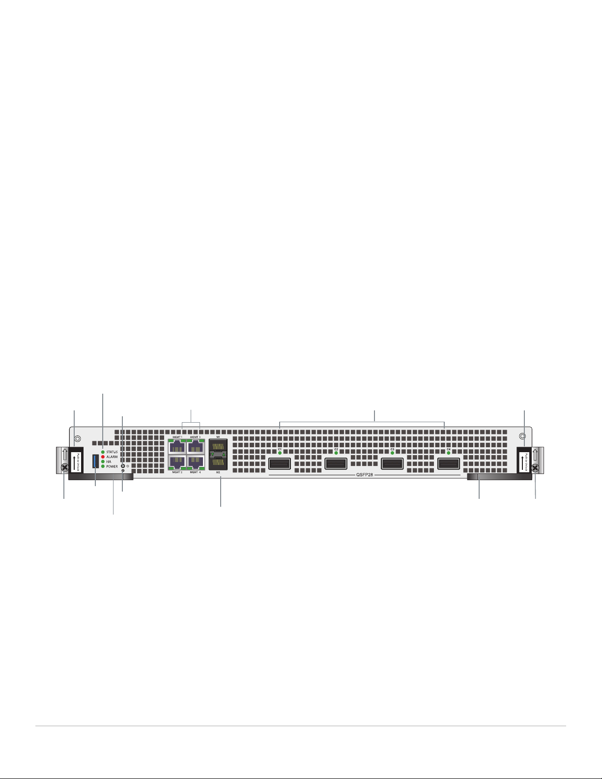
FIM-7920E
Power
Slider
Module
Lever
Secure
Screw
Module
Lever
Power
Slider
Secure
Screw
C1 to C4
100GigE Fabric Channel
QSFP28 Network
Interfaces (data)
M1 and M2 10GigE Base
Channel SFP+ Interfaces
(heartbeat and management)
MGMT1 - MGMT4
10/100/1000BASE-T Copper
Management Interface
Status, Alarm
HA, and Power
LEDS
USB
Power
Button
NMI
Button
The FIM-7920E interface module is a hot swappable module that provides data, management, and session
sync/heartbeat interfaces, base backplane switching, and fabric backplane session-aware load balancing for a
FortiGate-7000 series chassis. The FIM-7920E includes an integrated switch fabric and DP2 processors to load balance
millions of data sessions over the 80Gbps fabric backplane channel to FPM processor modules. The FIM-7920E also
includes a 1Gbps base backplane channel for base backplane management communication with each FPMmodule in
the chassis, one 40Gbps fabric backplane channel for fabric backplane communication with the FIM module(s) in the
chassis, and a second 1Gbps base backplane channel for base backplane communication with the FIM module(s) in the
chassis.
The FIM-7920E can be installed in any FortiGate-7000 series chassis in chassis hub/switch slots 1 or 2. The FIM-7920E
provides four Quad Small Form-factor Pluggable 28 (QSFP28) 100GigE interfaces for a FortiGate-7000 chassis. Using
a 100GBASE-SR4 QSFP28 or 40GBASE-SR4 QSFP+ transceiver, each QSFP28 interface can also be split into four
10GBASE-SR SFP+ interfaces.
You can also install FIM-7920Es in a second chassis and operate the chassis in HA mode to provide chassis failover
protection.
FIM-7920E front panel
Mounting hardware
Module levers
Use the module levers, power sliders, and secure screws to insert, secure and remove the module from the chassis.
Carefully slide the module all of the way into the chassis slot and fully close the module levers to seat the module into
the chassis slot and to connect the module to the chassis backplane connectors. When both module levers are fully
FIM-7920E Processing Module Guide Fortinet Technologies Inc.
Page 6

FIM-7920E interface module 6
closed, the power sliders can be lowered to their bottom position, locking the module levers and turning on power to the
module.
Raise the power sliders to unlock the module levers and turn off module power. Then open the module levers to eject
the module from the backplane connectors; allowing the module to be removed from the chassis.
The module lever mechanism helps reduce the engagement force required to insert or eject the module from the
backplane connectors.
The module levers do not fully secure the module in the chassis. The secure screws must be tightened to reliably secure
the module in the chassis and to make sure the module remains securely connected to the backplane for power and
network connectivity.
Power sliders
Close the module levers and move the power sliders to their bottom position to lock the module levers and turn the
module power switch on.
Move the power sliders to the top position to unlock the module levers and turn the module power switch off.
Gently push the power sliders down to make sure they are in their bottom position. If the module LEDs do not light the
module is not receiving power. If this happens check the power sliders to make sure they are in their bottom position.
Secure screws
Fully tighten the secure screws to lock the module in the chassis providing a secure and reliable connection with the
backplane.
Loosen the secure screws before ejecting the module from the chassis.
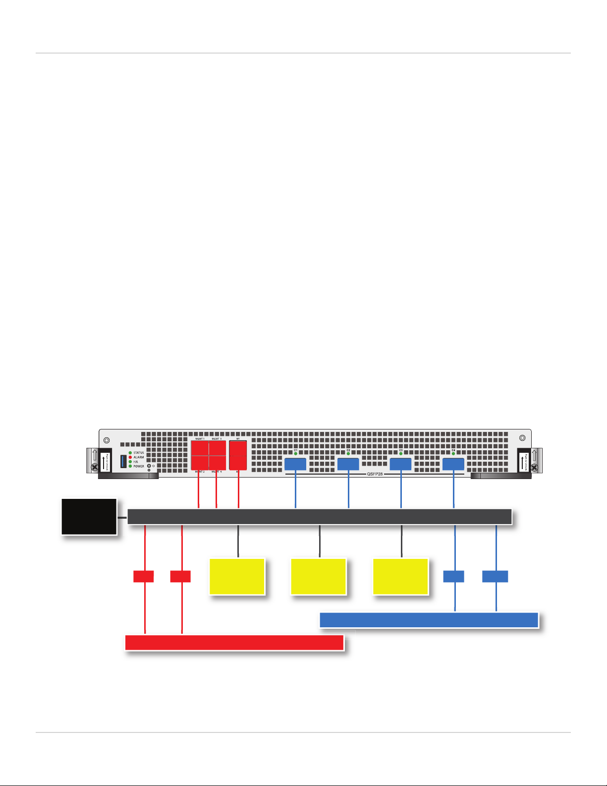
Front panel interfaces
You connect the FIM-7920E to your 100Gbps networks using the C1 to C4 front panel QSFP28 interfaces. The front
panel also includes M1 and M2 SFP+ interfaces for the base channel, four Ethernet management interfaces (MGMT1 to
MGMT4), and a USB port. The USB port can be used with any USB key for backing up and restoring configuration files.
Connector Type Speed Protocol Description
C1 to C4 QSFP28 100Gbps/40Gbps/10Gbps Ethernet Four front panel 100GigE QSFP28 fabric
channel interfaces that can be connected to
100Gbps networks to distribute sessions to
the FPM processor modules installed in
chassis slots 3 and up. Using a 100GBASESR4 QSFP28 or 40GBASE-SR4 QSFP+
transceiver, each QSFP28 interface can
also be split into four 10GBASE-SR
interfaces. These interfaces also support
creating link aggregation groups (LAGs)
FIM-7920E Processing Module Guide Fortinet Technologies Inc.
Page 7

FIM-7920E interface module 7
Connector Type Speed Protocol Description
that can include interfaces from multiple
FIM-7920Es.
M1 and M2 SFP+ 10Gbps/1Gbps Ethernet Two front panel 10GigE SFP+ interfaces
that connect to the base backplane
channel. These interfaces are used for
heartbeat, session sync, and management
communication between FIM-7920Es in
different chassis. These interfaces can also
be configured to operate as Gigabit
Ethernet interfaces using SFP transceivers,
but should not normally be changed. If you
use switches to connect these interfaces,
the switch ports should be able to accept
packets with a maximum frame size of at
least 1526. The M1 and M2 interfaces need
to be on different broadcast domains. If M1
and M2 are connected to the same switch,
Q-in-Q must be enabled on the switch
MGMT1 to
MGMT4
USB USB 3.0
RJ-45 10/100/1000Mbps Ethernet Four 10/100/1000BASE-T copper out of
band management Ethernet interfaces.
Type A
USB 3.0
USB 2.0
Standard USB connector.
Physical description
Dimensions 1.88 x 17.11 x 18.49 in. (48 x 435 x 470 mm) (Height x Width x Length)
Weight 16.6 lb. (7.6 kg)
Operating Temperature 32 to 104°F (0 to 40°C)
Storage Temperature -31 to 158°F (-35 to 70°C)
Relative Humidity 10% to 90% (Non-condensing)
Power consumption Max: 460W; Average: 410W
Max Current 38.3 A
Heat Dissipation 1565BTU/h
Joules/h 1644KJ/h
FIM-7920E Processing Module Guide Fortinet Technologies Inc.
Page 8

FIM-7920E interface module 8
Front panel LEDs
From the FIM-7920E font panel you can view the status of the module LEDs to verify that the module is functioning
normally.
LED State Description
Off The FIM-7920E is powered off.
STATUS
ALARM Red Major alarm.
HA
POWER Green The FIM-7920E is powered on and operating normally.
C1 to C4
Green The FIM-7920E is powered on and operating normally.
Flashing Green The FIM-7920E is starting up.
Amber Minor alarm
Off No alarms
Off The FIM-7920E is operating in normal mode.
Green The FIM-7920E is operating in HA mode.
Red A failover has occurred
Off The FIM-7920E is powered off.
Green The correct cable is connected to the interface and the connected equipment
has power and is connected at 100Gbps or 40Gbps. If the port is split the LED
will light as long as at least one of the 10Gbps connections is active.
Flashing Green Network activity at the interface.
Off No link is established.
M1 and M2 Green The correct cable is connected to the interface and the connected equipment
has power.
Flashing Green Network activity at the interface.
Off No link is established.
Solid Green Indicates this interface is connected with the correct cable and the attached
MGMT1-4
Link/Act
MGMT1-4
Speed
FIM-7920E Processing Module Guide Fortinet Technologies Inc.
Blinking Green Indicates network traffic on this interface.
Off No Link
Green Connection at 1Gbps.
Amber Connection at 100Mbps.
Off Connection at 10Mbps.
network device has power.
Page 9

FIM-7920E interface module 9
FIM-7920E C1 to C4 interface combinations
The following table shows the different combinations of interface speeds that you can set up with the FIM-7920E C1 to
C4 front panel interfaces.
100GE QSFP28 4 3 3 2 2 2 1 1 1 1 x x x x x
40GE QSFP+ x 1 x 2 1 x 3 2 1 x 4 3 2 1 x
10Ge SFP+ x x 4 x 4 8 x 4 8 12 x 4 8 12 16
Supported transceivers and breakout cables
Transceivers available from Fortinet for the FIM-7920E C1 to C4 QSFP28 interfaces.
Transceiver Description
FG-TRAN-QSFP28-SR4 100 GE QSFP28 transceivers, 4 channel parallel fiber, short range.
FG-TRAN-QSFP28-LR4 100 GE QSFP28 transceivers, 4 channel parallel fiber, long range.
FG-TRAN-QSFP+SR 40GE QSFP+ transceivers, short range.
FG-TRAN-QSFP+LR 40GE QSFP+ transceivers, long range.
Breakout cables available from Fortinet for the FIM-7920E C1 to C4 QSFP28 interfaces.
Breakout Description
FG-TRAN-QSFP-4XSFP 40GE QSFP+ Parallel Breakout Active Optical Cable with 1m length.
FG-TRAN-QSFP-4SFP-5 40G QSFP+ Parallel Breakout MPO to 4xLC connectors, 5m reach.
Changing the interface type and splitting the FIM-7920E C1 to C4 interfaces
By default, the FIM-7920E C1 to C4 interfaces are configured as 100GE QSFP28 interfaces. You can use the following
command to convert them to 40GE QSFP+ interfaces. Once converted, you can use the other command below to split
them into four 10GBASE-SR interfaces.
Changing the interface type
For example, to change the interface type of the C1 interface of the FIM-7920E in slot 1 to 40GE QSFP+ connect to the
CLI of your FortiGate-7000 system using the management IP and enter the following command:
config system global
set qsfp28-40g-port 1-C1
FIM-7920E Processing Module Guide Fortinet Technologies Inc.
Page 10

FIM-7920E interface module 10
end
The FortiGate-7000 system reboots and when it starts up interface C1 of the FIM-7920E in slot 1 is operating as a 40GE
QSFP+ interface .
To change the interface type of the C3 and C4 ports of the FIM-7920E in slot 2 to 40GE QSFP+ enter the following
command:
config system global
set qsfp28-40g-port 2-C3 2-C4
end
The FortiGate-7000 system reboots and when it starts up interfaces C3 and C4 of the FIM-7920E in slot 2 are operating
as a 40GE QSFP+ interfaces.
Splitting the C1 to C4 interfaces
Each 40GE interface (C1 to C4) on the FIM-7920Es in slot 1 and slot 2 of a FortiGate-7000 system can be split into 4 x
10GBE interfaces. You split these interfaces after the FIM-7920Es are installed in your FortiGate-7000 system and the
system us up and running. You can split the interfaces of the FIM-7920Es in slot 1 and slot 2 at the same time by
entering a single CLI command. Enabling, disabling, or changing the split interfaces configuration requires a system
reboot. Fortinet recommends that you split multiple interfaces at the same time according to your requirements to avoid
traffic disruption.
For example, to split the C1 interface of the FIM-7920E in slot 1 (this interface is named 1-C1) and the C1 and C4
interfaces of the FIM-7920E in slot 2 (these interfaces are named 2-C1 and 2-C4) connect to the CLI of your FortiGate7000 system using the management IP and enter the following command:
config system global
set split-port 1-C1 2-C1 2-C4
end
After you enter the command, the FortiGate-7000 reboots and when it comes up:
l The 1-C1 interface will no longer be available. Instead the 1-C1/1, 1-C1/2, 1-C1/3, and 1-C1/4 interfaces will be
available.
l The 2-C1 interface will no longer be available. Instead the 2-C1/1, 2-C1/2, 2-C1/3, and 2-C1/4 interfaces will be
available.
l The 2-C4 interface will no longer be available. Instead the 2-C4/1, 2-C4/2, 2-C4/3, and 2-C4/4 interfaces will be
available.
You can now connect breakout cables to these interfaces and configure traffic between them just like any other
FortiGate interface.
Turning the module on and off
You can use the front panel power button to turn the FIM-7920E power on or off. If the FIM-7920E is powered on, press
the power switch to turn it off. If the FIM-7920E is turned off and installed in a chassis slot, press the power button to
turn it on.
FIM-7920E Processing Module Guide Fortinet Technologies Inc.
Page 11
FIM-7920E interface module 11
1G
FIM-7920E
Chassis Base Backplane
Chassis Fabric Backplane
CPU
Integrated Switch Fabric
Management
(MGMT1-4)
Heartbeat
(M1 M2)
Data
(C1 - C4)
DP2 DP2 DP2
1G
80G
40G
NMI switch
When working with Fortinet Support to troubleshoot problems with the FIM-7920E you can use the front panel nonmaskable interrupt (NMI) switch to assist with troubleshooting. Pressing this switch causes the software to dump
registers/backtraces to the console. After the data is dumped the FIM-7920E reboots. While the FIM-7920E is
rebooting, traffic is temporarily blocked. The FIM-7920E should restart normally and traffic can resume once the it is up
and running.
FIM-7920E hardware architecture
The FIM-7920E includes an integrated switch fabric (ISF) that connects the front panel interfaces to the DP2 sessionaware load balancers and to the chassis backplanes. The ISFalso allows the DP2 processors to distribute sessions
among all NP6 processors on the FPMmodules in the same chassis.
The FIM-7920E also includes the following backplane communication channels:
l One 80Gbps fabric backplane channel to distribute traffic to the FPMs.
l One 1Gbps base backplane channel for base backplane communication with the FPMs.
l One 40Gbps fabric backplane channel for fabric backplane communication with the other FIM.
l One 1Gbps base backplane channel for base backplane communication with the other FIM.
FIM-7920E hardware architecture
FIM-7920E Processing Module Guide Fortinet Technologies Inc.
Page 12

Hardware installation
This chapter describes installing a FIM-7920E interface module into a FortiGate-7000 chassis.
Installing QSFP28, QSFP+, SFP+, and SFP transceivers
You must install QSFP28 or QSFP+, transceivers into the FIM-7920E front panel C1 to C4 fabric channel interfaces
before connecting them to 100Gbps or 40Gbps networks (10Gbps networks if splitting one or more interfaces into
10GBASE-SR SFP+ interfaces). You can install the transceivers before or after inserting the FIM-7920E module into a
chassis.
You must install SFP+ transceivers into the FIM-7920E M1 and M2 interfaces before connecting them to 10Gbps
networks. The FIM-7920E ships with two 10GBASE-SR SFP+ transceivers. You can also configure the M1 and M2
interfaces to operate at 1Gbps and install SFP transceivers. You can install these transceivers before or after inserting
the FIM-7920E board into a chassis.
You can install the following types of transceivers for connectors M1 and M2:
l 10GBASE-SR SFP+ (10Gbps)
l 10GBASE-LR SFP+ (10Gbps)
l 1000BASE SFP (1Gbps)
The M1 and M2 interfaces are used for heartbeat, session sync, and management
communication between FIM-7920Es in different chassis. This communication requires 10
Gbps connections so, even though it supported, the M1 and M2 interfaces should not
changed to 1000Base SFP 1Gbps interfaces.
To install transceivers
To complete this procedure, you need:
l A FIM-7920E
l Transceivers to install
l An electrostatic discharge (ESD) preventive wrist strap with connection cord
FIM-7920Es must be protected from static discharge and physical shock. Only handle or work
with FIM-7920Es at a static-free workstation. Always wear a grounded electrostatic discharge
(ESD) preventive wrist strap when handling FIM-7920Es.
Handling the transceivers by holding the release latch can damage the connector. Do not
force transceivers into their cage slots. If the transceiver does not easily slide in and click into
place, it may not be aligned correctly. If this happens, remove the transceiver, realign it and
slide it in again.
FIM-7920E Processing Module Guide Fortinet Technologies Inc.
Page 13

Hardware installation 13
Front mounting
bracket
Optional front
cable management
brackets
Left cable
management
bracket
Right cable
management
bracket
M4x 8 l ar ge hea d
pan he ad sc rew s
M4x 8 l ar ge hea d
pan he ad sc rew s
M4x 8 f la t-h ead
scr ews
M4x 8 f la t-h ead
scr ews
Front mounting
bracket
Power cord
clamp
1.
Attach the ESD wrist strap to your wrist and to an available ESD socket or wrist strap terminal.
2.
Remove the caps from the cage sockets on the FIM-7920E front panel.
3.
Hold the sides of the transceiver and slide it into the cage socket until it clicks into place.
Installing the optional front cable management bracket
Your FIM-7920E package includes a front cable management bracket. This bracket helps support the relatively large
QSFP28 transceivers used to connect the front panel C1 to C4 interfaces to your networks.
Using the front cable management bracket is optional, but if you decide to use the bracket it should be attached to the
FortiGate-7000 chassis left and right cable management brackets.
Install one front cable management bracket for each FIM-7920E after you have installed the FIM-7920E in your
FortiGate-7000 chassis.
Installing FIM-7920E front cable management brackets in a FortiGate-7040E chassis
FIM-7920E Processing Module Guide Fortinet Technologies Inc.
Page 14

Hardware installation 14
Closed
Secure Screw
Module Lever
Power Slider
Power Slider
Alignment Pin
Module Lever
Secure Screw
Alignment Pin
Open
(to open move the power slider up about 2 mm)
FIM-7920E mounting hardware
To install a FIM-7920E you slide the module into a hub/switch slot in the front of an FortiGate-7000 series chassis
(either slot 1 or 2) and then use the mounting hardware, described in Mounting hardware on page 5, to lock the module
into place in the slot. When locked into place and positioned correctly, the module front panel is flush with the chassis
front panel and connected to the chassis backplane.
To position the module correctly you must use the mounting hardware shown below for the right of the FIM-7920E front
panel. The mounting hardware on the left of the front panel is the same but reversed. The FIM-7920E mounting
hardware aligns the module in the chassis slot and is used to insert and eject the module from the slot.
On some FIM modules there may be very little clearance between the front panel interfaces
and the module lever on the right side of the FIM-7920E. In fact, you may have to remove
network connectors from some front panel interfaces to open the module lever. In most cases
you should remove all network connectors from the front panel before opening the module
levers to remove an FIM module from a chassis slot.
FIM-7920E mounting hardware
The FIM-7920E module levers align the module in the chassis slot and insert and eject the module from the slot. The
power sliders activate micro switches that turn on or turn off power to the module. When both sliders are raised, the
module cannot receive power. When the sliders are fully closed, the module can receive power if it is fully inserted into a
chassis slot.
FIM-7920E Processing Module Guide Fortinet Technologies Inc.
Page 15
Hardware installation 15
Inserting a FIM-7920E module into a chassis
This procedure describes how to insert a FIM-7920E module into slot 1 or 2 of a FortiGate-7000 chassis. The procedure
includes photographs to illustrate the procedure steps. The photos were taken in one of Fortinet's hardware labs using a
generic module and FortiGate-7000 chassis.
You must carefully slide the module all the way into the chassis slot, close the module levers
to seat the module into the slot, and tighten the secure screws to make sure the module is
fully engaged with the backplane and secured. You must also make sure that the power
sliders are fully closed by gently pushing them down.
Installation Highlights:
1. Module levers must be closed.
2. Secure screws must be tightened.
3. Power sliders must be fully closed for the module to get power and start up.
If the module is not receiving power all LEDs remain off.
FIM-7920E modules are hot swappable. This procedure is the same whether or not the chassis is powered on.
Do not carry the FIM-7920E module by holding the module levers or secure screws. When
inserting or removing the FIM-7920E from a chassis slot, handle the module by the front
panel. The levers are not designed for carrying the module. If the levers become bent or
damaged, the FIM-7920E may not align correctly in the chassis slot.
To complete this procedure, you need the following equipment and tools:
l a FIM-7920E
l a FortiGate-7000 chassis with an empty slot
l an electrostatic discharge (ESD) preventive wrist strap with connection cord
l a Phillips screwdriver
FIM-7920Es must be protected from static discharge and physical shock. Only handle or work
with FIM-7920Es at a static-free workstation. Always wear a grounded electrostatic discharge
(ESD) preventive wrist strap when handling FIM-7920Es. Attach the ESD wrist strap to your
wrist and to an ESD socket or to a bare metal surface on the chassis or frame. (An ESD wrist
strap is not visible in the photographs below because they were taken in an ESD safe lab
environment.)
1. Remove the FIM-7920E module from its packaging.
The module levers are closed when you first remove a new module from its packaging.
FIM-7920E Processing Module Guide Fortinet Technologies Inc.
Page 16
Hardware installation 16
Module levers Module levers
Slide in slowly
Stop position
Levers pop open
Power
slider
up
Power
slider
up
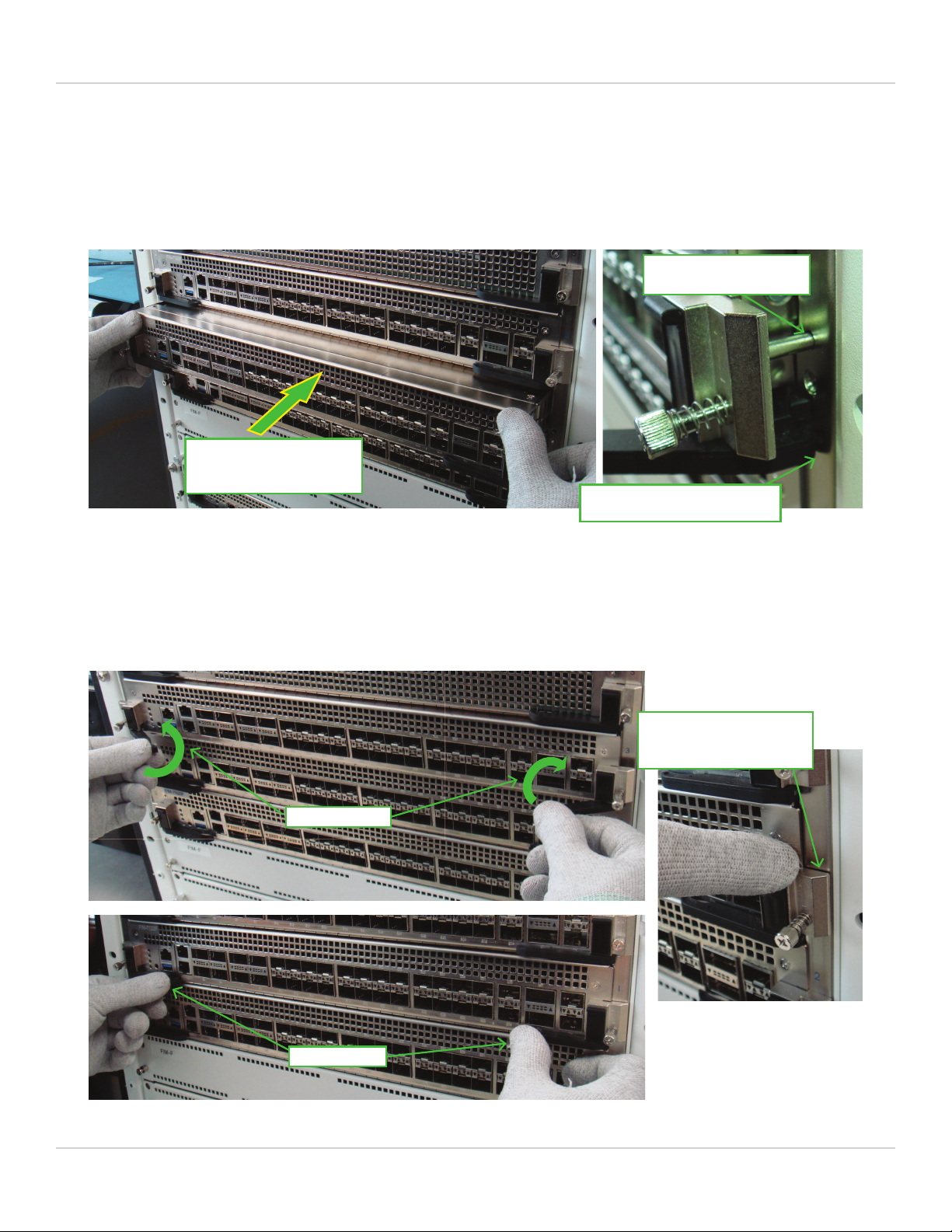
2. Align the module with the chassis slot, slowly slide the module into the slot, stop at
about 1-2 inches from fully inserting it.
3. Unlock the left and right module levers by pushing the power sliders up until the
levers pop open.
Before sliding the final portion of the module into the chassis fully open both levers by pushing the power sliders up.
Fully open both levers to avoid damaging the lever mechanism. Damaging the levers can prevent the module from
connecting to power.
FIM-7920E Processing Module Guide Fortinet Technologies Inc.
Page 17
Hardware installation 17
Module alignment pin
inserted into chassis
Apply moderate force to
push the module slowly
into the slot.
Stop Position
Levers engage with chassis
Levers closed
Rotate to close
Small gap between the
module and the chassis
when levers are closed.
4. Continue pushing the module into the slot until the levers engage with the sides of
the chassis slot.
Insert the module by applying moderate force to the front faceplate (not the levers) to slide the module into the slot. The
module should glide smoothly. If you encounter any resistance, the module could be aligned incorrectly. Pull the module
back out and try inserting it again.
5. Close both levers by pushing them into contact with the module front panel.
Closing the levers draws the module into the chassis slot and connects the module rear connectors to the chassis
backplane. The design of the levers leaves gaps to compensate for tolerances. So even when the levers are fully closed,
the module may not be fully into position and in contact with the chassis backplane.
FIM-7920E Processing Module Guide Fortinet Technologies Inc.
Page 18
Hardware installation 18
After tightening both secure
screws, the module is fully
engaged with the chassis.
Tighten by hand
Fully tighten with a
screwdriver
6. Tighten both secure screws to close the gap between the module and the chassis.
Begin by engaging the secure screws into the chassis tapped hole by hand and roughly tighten them. Then use a Phillips
screwdriver to fully tighten the two secure screws. Do not use a power screwdriver, because the high torque and speed
can damage the chassis or screw thread. After tightening both secure screws, the module is fully seated in the chassis
slot and the module connectors are fully in contact with the chassis backplane.
FIM-7920E Processing Module Guide Fortinet Technologies Inc.
Page 19

Hardware installation 19
Levers locked
Power slider
down to bottom
Power slider
down to bottom
7. Push down both power sliders to make sure the module power switch is on.
When the module is fully in position, the power sliders should drop down, lock the levers, and turn module power on.
Gently push both power sliders down to their bottom position to make sure they are fully closed.
8. If the chassis is powered on, check the modle LEDs to verify that the module is
operating correctly
LED Normal operation state
Status Green
Alarm Off
HA Off
Power Green
Shutting down and removing a FIM-7920E module from a chassis
This procedure describes how to shut down and remove a FIM-7920E module from FortiGate-7000 chassis. The
procedure includes photographs to illustrate the procedure steps. The photos were taken in one of Fortinet's hardware
labs using a generic module and FortiGate-7000 chassis.
FIM-7920Es are hot swappable. This procedure is the same whether or not the chassis is powered on.
FIM-7920E Processing Module Guide Fortinet Technologies Inc.
Page 20

Hardware installation 20
Do not carry the FIM-7920E by holding the module levers or secure screws. When inserting or
removing the FIM-7920E from a chassis slot, handle the module by the front panel. The
levers are not designed for carrying the module. If the levers become bent or damaged, the
FIM-7920E may not align correctly in the chassis slot.
To complete this procedure, you need the following equipment and tools:
l a FortiGate-7000 chassis with a FIM-7920E module installed
l an electrostatic discharge (ESD) preventive wrist strap with connection cord
l a Phillips screwdriver
FIM-7920Es must be protected from static discharge and physical shock. Only handle or work
with FIM-7920Es at a static-free workstation. Always wear a grounded electrostatic discharge
(ESD) preventive wrist strap when handling FIM-7920Es. (An ESD wrist strap is not visible in
the photographs below because they were taken in an ESD safe lab environment.)
1. Shut down the module operating system properly.
To avoid potential hardware problems, always shut down the module operating system properly before removing the
module from a chassis slot or before powering down the chassis. To shutdown the module, connect to the module GUI
and select Shutdown from the administrator menu. Or, from the module CLI,enter the execute shutdown
command.
2. Disconnect all cables from the module, including all network cables and USB cables
or keys.
FIM-7920E Processing Module Guide Fortinet Technologies Inc.
Page 21

Hardware installation 21
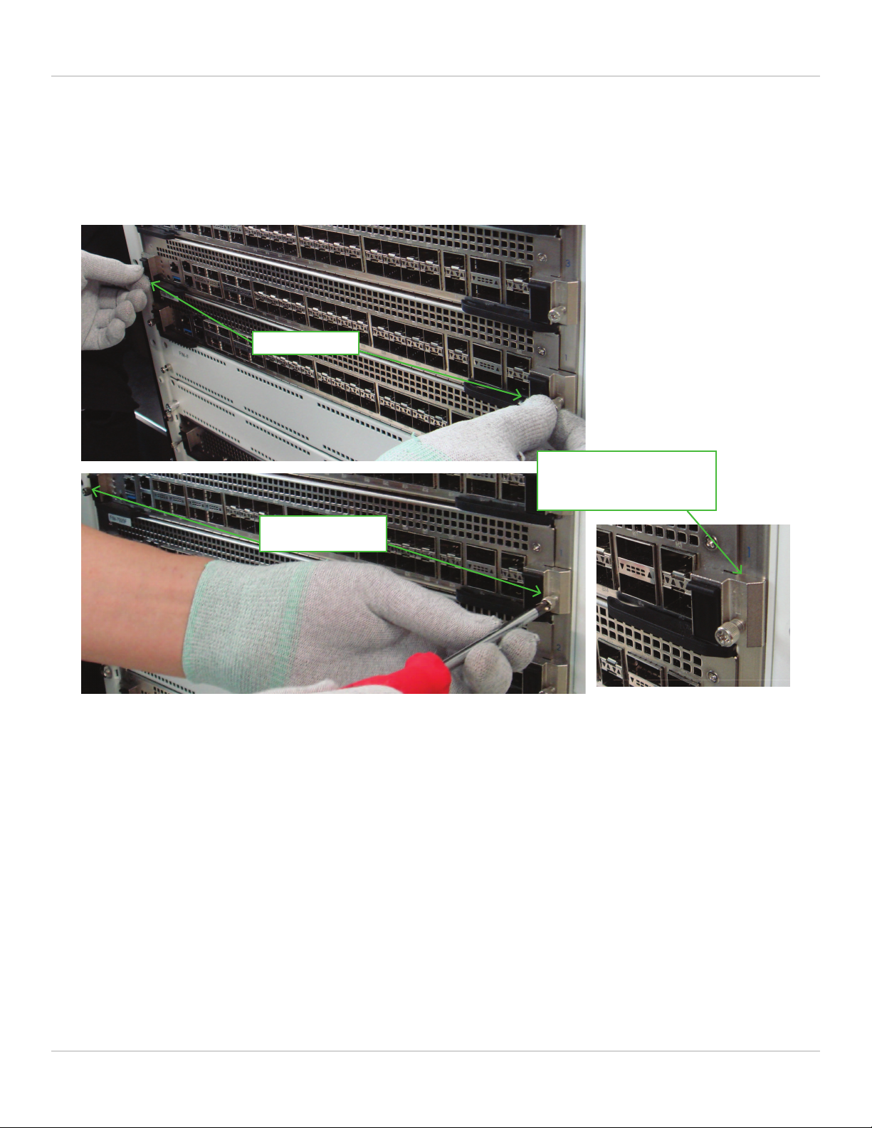
Use a Phillips screwdriver to
loosen both screws.
Fully loosen both
screws by hand.
3. Use a Phillips screwdriver to loosen both secure screws and then fully loosen them
by hand.
Fully loosen the secure screws, otherwise the levers may be damaged when used to eject the module from the chassis
slot. Do not use a power screwdriver, because the high torque and speed can damage the chassis or screw thread.
FIM-7920E Processing Module Guide Fortinet Technologies Inc.
Page 22

Hardware installation 22
Levers pop open
Power
slider
up
Power
slider
up
4. Unlock the left and right levers by pushing the power sliders up until the levers pop
open.
Push the power sliders up to fully open both levers. If the chassis is powered on, this step turns off the module’s power.
FIM-7920E Processing Module Guide Fortinet Technologies Inc.
Page 23

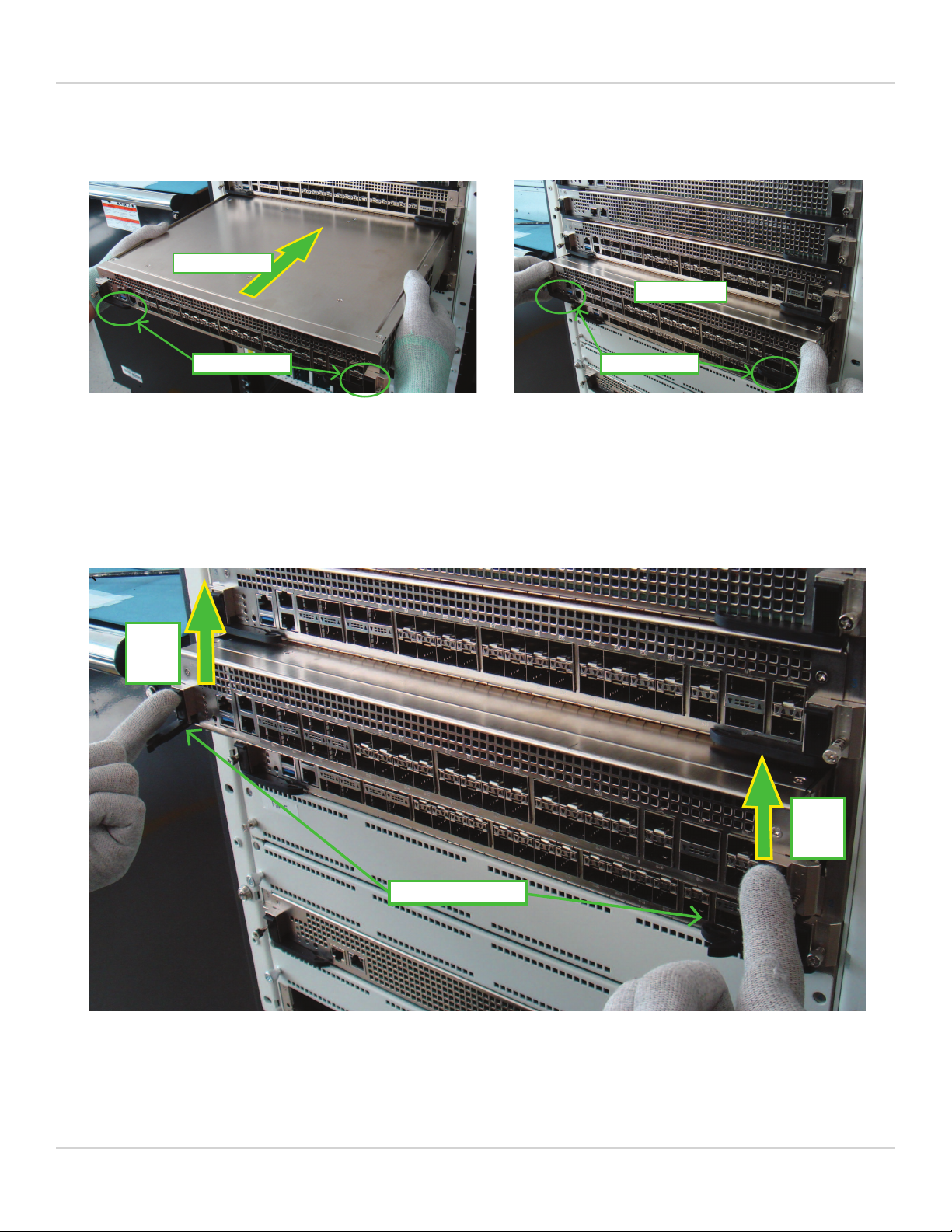
Hardware installation 23
Levers opened
Rotate to open
Module ejects
Module ejected
5. Use moderate force to fully open the levers and eject the module from the chassis.
6. Hold the levers to slide the module part way out of the chassis slot. Then grasp the
module by the sides and carefully slide it out of the slot.
FIM-7920E Processing Module Guide Fortinet Technologies Inc.
Page 24

Hardware installation 24
Troubleshooting
This section describes some common troubleshooting topics:
FIM-7920E does not startup
Positioning of FIM-7920E mounting hardware and a few other causes may prevent a FIM-7920E from starting up
correctly.
Power sliders and module levers not fully closed
If the power sliders or module levers are damaged or positioned incorrectly, the FIM-7920E may not start up. Make sure
the sliders are fully closed and the levers are correctly aligned, fully inserted, and locked and the secure screws are
tightened.
Firmware problem
If the FIM-7920E is receiving power and the sliders and levers are fully closed, and you have restarted the chassis and
the FIM-7920E still does not start up, the problem could be with FortiOS. Connect to the FIM-7920E console and try
cycling the power to the board. If the BIOS starts up, interrupt the BIOS startup and install a new firmware image. See
your FortiGate-7000 chassis system guide for information about accessing and installing firmware on individual
modules.
If this does not solve the problem, contact Fortinet Technical Support.
FIM-7920E status LED is flashing during system operation
Normally, the FIM-7920E Status LED is off when the FIM-7920E is operating normally. If this LED starts flashing while
the module is operating, a fault condition may exist. At the same time the FIM-7920E may stop processing traffic.
To resolve the problem you can try removing and reinserting the FIM-7920E in the chassis slot. Reloading the firmware
may also help.
If this does not solve the problem there may have been a hardware failure or other problem. Contact Fortinet Technical
Support for assistance.
FIM-7920E Processing Module Guide Fortinet Technologies Inc.
Page 25

Quick FIM-7920E configuration
This section is a quick start guide to connecting and configuring a FIM-7920E for your network.
Before using this chapter, your FortiGate-7000 chassis should be mounted and connected to your power system. In
addition, your FIM-7920Es should be inserted into the chassis in slots 1 or 2 and one or more processor modules should
be installed in chassis slots 3 and up. The chassis and the modules should also be powered up and the front panel LEDs
should indicate that the modules are functioning normally. As well the FIM-7920E and the processor modules should be
running the same FortiOS firmware version.
Registering your FortiGate-7000 series products
FortiGate-7000 series products are registered according to the chassis serial number. You need to register your chassis
to receive Fortinet customer services such as product updates and customer support. You must also register your
product for FortiGuard services. Register your product by visiting https://support.fortinet.com. To register, enter your
contact information and the serial numbers of the Fortinet products that you or your organization have purchased.
Choosing the configuration tool
You can use either the GUI or the Command Line Interface (CLI) to configure the FIM-7920E. Some basic configuration
settings can only be done from the CLI. You can connect to the GUI using HTTP or HTTPS, You can connect to the
CLIusing SSH or Telent or by a direct console connection to the FIM-7920E Console port. Use a terminal emulator with
the following settings to connect to the console port: bits per second: 9600, data bits: 8, parity: none, stop bits: 1, flow
control: none.
Changing network settings
The FIM-7920E ships with the following factory default configuration.
Option Default configuration
Administrator Account User
Name
Password (none) For security reasons you should add a password to the admin
MGMT1 to MGMT4
IP/Netmask
admin
account before connecting the FIM-7920E to your network.
192.168.1.99/24
FIM-7920E Processing Module Guide Fortinet Technologies Inc.
Page 26

Quick FIM-7920E configuration 26
MGMT 1 to MGMT 4 of each FIM-7920E are configured as a static aggregate interface called mgmt and all have the
same IP address. If you have two FIM modules installed in your chassis, then MGMT 1 to MGMT 4 of both modules are
all in the same static aggregate interface.
At any time during the configuration process, if you run into problems, you can reset the FIM-7920E to the factory
defaults and start over. From the CLI enter execute factoryreset.
Connect to the GUIby connecting MGMT1 of the module in slot 1 to your network and browsing to
https://192.168.1.99. Log into the GUI using the admin account with no password. Go to Network > Interface and
configure the FIM-7920E interfaces to connect to your network.
FIM-7920E Processing Module Guide Fortinet Technologies Inc.
Page 27

Cautions and warnings
Environmental specifications
Ambient operating temperature: 0°C to 40°C
Rack Mount Instructions - The following or similar rack-mount instructions are included with the installation instructions:
Instructions de montage en rack - Les instructions de montage en rack suivantes ou similaires sont incluses avec les
instructions d'installation:
Elevated Operating Ambient - If installed in a closed or multi-unit rack assembly, the operating ambient temperature
of the rack environment may be greater than room ambient. Therefore, consideration should be given to installing the
equipment in an environment compatible with the maximum ambient temperature (Tma) specified by the manufacturer.
Température ambiante élevée - S'il est installé dans un rack fermé ou à unités multiples, la température ambiante de
fonctionnement de l'environnement du rack peut être supérieure à la température ambiante de la pièce. Par
conséquent, il est important d’installer le matériel dans un environnement respectant la température ambiante
maximale (Tma) stipulée par le fabricant.
Reduced Air Flow - Installation of the equipment in a rack should be such that the amount of air flow required for safe
operation of the equipment is not compromised.
Ventilation réduite - Installation de l'équipement dans un rack doit être telle que la quantité de flux d'air nécessaire au
bon fonctionnement de l'équipement n'est pas compromise.
Mechanical Loading - Mounting of the equipment in the rack should be such that a hazardous condition is not
achieved due to uneven mechanical loading.
Chargement Mécanique - Montage de l'équipement dans le rack doit être telle qu'une situation dangereuse n'est pas
lié à un chargement mécanique inégal.
Circuit Overloading - Consideration should be given to the connection of the equipment to the supply circuit and the
effect that overloading of the circuits might have on overcurrent protection and supply wiring. Appropriate consideration
of equipment nameplate ratings should be used when addressing this concern.
Surtension - Il convient de prendre l’ensemble des précautions nécessaires lors du branchement de l’équipement au
circuit d’alimentation et être particulièrement attentif aux effets de la suralimentation sur le dispositif assurant une
protection contre les courts-circuits et le câblage. Ainsi, il est recommandé de tenir compte du numéro d’identification
de l’équipement.
Reliable Earthing - Reliable earthing of rack-mounted equipment should be maintained. Particular attention should be
given to supply connections other than direct connections to the branch circuit (e.g. use of power strips).
Fiabilité de la mise à la terre - Fiabilité de la mise à la terre de l'équipement monté en rack doit être maintenue. Une
attention particulière devrait être accordée aux connexions d'alimentation autres que les connexions directes au circuit
de dérivation (par exemple de l'utilisation de bandes de puissance).
Equipment must be used only with UL Listed ITE or Equivalent.
L'équipement doit être utilisé uniquement avec UL ITE ou équivalent.
FIM-7920E Processing Module Guide Fortinet Technologies Inc.
Page 28

Cautions and warnings 28
Refer to specific Product Model Data Sheet for Environmental Specifications (Operating Temperature, Storage
Temperature, Humidity, and Altitude).
Référez à la Fiche Technique de ce produit pour les caractéristiques environnementales (Température de
fonctionnement, température de stockage, humidité et l'altitude).
Safety
Moving parts - Hazardous moving parts. Keep away from moving fan blades.
Pièces mobiles - Pièces mobiles dangereuses. Se tenir éloigné des lames mobiles du ventilateur.
Warning: Equipment intended for installation in Restricted Access Location.
Avertissement: Le matériel est conçu pour être installé dans un endroit où l’accès est restreint.
Battery - Risk of explosion if the battery is replaced by an incorrect type. Do not dispose of batteries in a fire. They may
explode. Dispose of used batteries according to your local regulations. IMPORTANT: Switzerland: Annex 4.10 of
SR814.013 applies to batteries.
Batterie - Risque d'explosion si la batterie est remplacée par un type incorrect. Ne jetez pas les batteries au feu. Ils
peuvent exploser. Jetez les piles usagées conformément aux réglementations locales. IMPORTANT: Suisse: l'annexe
4.10 de SR814.013 s’appliquent aux batteries.
警告
本電 池 如果 更 換 不 正確 會 有爆 炸 的 危 險
請依 製 造商 說明 書 處理 用 過之 電 池
CAUTION: There is a danger of explosion if a battery is incorrect replaced. Replace only with the same or equivalent
type. Dispose batteries of according to the manufacturer’s instructions. Disposing a battery into fire, a hot oven,
mechanically crushing, or cutting it can result in an explosion. Leaving a battery in an extremely hot environment can
result in leakage of flammable liquid, gas, or an explosion. If a battery is subjected to extremely low air pressure, it may
result in leakage of flammable liquid, gas, or an explosion.
WARNUNG: Lithium-Batterie Achtung: Explosionsgefahr bei fehlerhafter Batteriewechsel. Ersetzen Sie nur den
gleichen oder gleichwertigen Typ. Batterien gemäß den Anweisungen des Herstellers entsorgen.
Beseitigung einer BATTERIE in Feuer oder einen heißen Ofen oder mechanisches Zerkleinern oder Schneiden einer
BATTERIE, die zu einer EXPLOSION führen kann.
Verlassen einer BATTERIE in einer extrem hohen Umgebungstemperatur, die zu einer EXPLOSION oder zum
Austreten von brennbarer Flüssigkeit oder Gas führen kann.
Eine BATTERIE, die einem extrem niedrigen Luftdruck ausgesetzt ist, der zu einer EXPLOSION oder zum Austreten
von brennbarer Flüssigkeit oder Gas führen kann.
Caution: Slide/rail mounted equipment is not to be used as a shelf or a work space.
Attention: Un équipement monté sur bâti ne doit pas être utilisé sur une étagère ou dans un espace de travail.
Fiber optic transceiver must be rated 3.3V, 22mA max, Laser Class 1, UL certified component.
Le transceiver optique doit avoir les valeurs nominales de 3.3 V, maximum 22 mA, Laser Class 1, homologué UL
FIM-7920E Processing Module Guide Fortinet Technologies Inc.
Page 29

Regulatory notices
Federal Communication Commission (FCC) – USA
This device complies with Part 15 of FCC Rules. Operation is subject to the following two conditions:
(1) this device may not cause harmful interference, and
(2) this device must accept any interference received; including interference that may cause undesired operation.
This equipment has been tested and found to comply with the limits for a Class A digital device, pursuant to Part 15 of
the FCC Rules. These limits are designed to provide reasonable protection against harmful interference when the
equipment is operated in a commercial environment. This equipment generates, uses, and can radiate radio frequency
energy, and if it is not installed and used in accordance with the instruction manual, it may cause harmful interference to
radio communications. Operation of this equipment in a residential area is likely to cause harmful interference, in which
case the user will be required to correct the interference at his own expense.
WARNING: Any changes or modifications to this product not expressly approved by the party responsible for
compliance could void the user’s authority to operate the equipment.
Industry Canada Equipment Standard for Digital Equipment (ICES) – Canada
CAN ICES-3 (A) / NMB-3 (A)
This digital apparatus does not exceed the Class A limits for radio noise emissions from digital apparatus set out in the
Radio Interference Regulations of the Canadian Department of Communications.
Cet appareil numérique n’émet pas de bruits radioélectriques dépassant les limites applicables aux appareils
numériques de la classe A prescrites dans le Règlement sur le brouillage radioélectrique édicte par le ministère des
Communications du Canada.
European Conformity (CE) - EU
This is a Class A product. In a domestic environment, this product may cause radio interference, in which case the user
may be required to take adequate measures.
FIM-7920E Processing Module Guide Fortinet Technologies Inc.
Page 30

Regulatory notices 30
Voluntary Control Council for Interference (VCCI) – Japan
この装置 は、クラスA機器 です。この装 置 を住宅 環 境 で使用 すると電波 妨 害 を引き起 こすことがあります。この場合 には使
用者 が適切 な対策 を講ずるよう要求 されることがあります。VCCI-A
Bureau of Standards Metrology and Inspection (BSMI) – Taiwan
The presence conditions of the restricted substance (BSMI RoHS table) are available at the link below:
限用 物 質含 有 情 況 表 (RoHS Table) 請到 以 下 網址 下 載 :
https://www.fortinet.com/bsmi
此為 甲 類資 訊 技 術 設備 ,於居住 環 境 中 使用 時 ,可 能會 造 成射 頻 擾 動 ,在 此 種情 況 下 ,使用者 會 被要 求 採 取 某
些適 當 的對 策 。
英屬 蓋 曼群 島 商 防 特網 股 份有 限 公 司 台灣 分 公司
地址 :台 北市 內湖區 行 愛 路 176號2樓
電話 :(02) 27961666
China
此为 A级 产 品,在 生 活 环境 中 ,该 产品 可 能会 造 成 无 线电 干 扰。这种 情 况 下,可 能需 要 用 户 对其 采 取切 实 可 行 的
措施 。
FIM-7920E Processing Module Guide Fortinet Technologies Inc.
Page 31

Copyright© 2019 Fortinet, Inc. All rights reserved. Fortinet®, FortiGate®, FortiCare® and FortiGuard®, and c ertain other marks are registered trademarks of Fortinet, Inc. , in
the U.S. and other jurisdictions, and other Fortinet names herein may also be registered and/or common law trademarks of Fortinet. All other product or company names may be
trademarks of their respective owners. Performance and other metrics contained herein were attained in internal lab tests under ideal c onditions, and actual performance and
other results may v ary. Network variables, different network environments and other conditions may aff ect performance results. Nothing herein represents any binding
commitment by Fortinet, and Fortinet disclaims all warranties, whether express or implied, except t o the extent F ortinet enters a binding writt en c ontract, signed by Fortinet’s
General Counsel, with a purchaser that expressly warrants t hat the identified product will perform according to certain expressly-identified performance metrics and, in such
event, only the specific performance metrics expressly identified in such binding written contract shall be binding on F ortinet. For absolute clarity, any s uch warranty will be
limited to performance in t he same ideal conditions as in Fortinet’s internal lab tests. In no event does Fortinet make any commitment related t o future deliverables, features or
development, and circumstances may change s uch that any f orward-lookingstatements herein are not accurate. Fortinet disclaims in full any covenants, representations, and
guarantees pursuant hereto, whether express or implied. Fortinet reserves the right to change, modify, transfer, or otherwise revise this publication without notice, and t he most
current version of the publication s hall be applicable.
 Loading...