

Fortinet FortiGate-7000, FortiGate-7040E, FortiGate-7904E, FortiGate-7901E, FortiGate-7030E Handbook
...Page 1
FortiOS™ Handbook - FortiGate-7000
7000
VERSION 5.4.5
Page 2

FORTINET DOCUMENTLIBRARY
http://docs.fortinet.com
FORTINETVIDEOGUIDE
http://video.fortinet.com
FORTINETBLOG
https://blog.fortinet.com
CUSTOMERSERVICE&SUPPORT
https://support.fortinet.com
http://cookbook.fortinet.com/how-to-work-with-fortinet-support/
FORTIGATECOOKBOOK
http://cookbook.fortinet.com
FORTINETTRAININGSERVICES
http://www.fortinet.com/training
FORTIGUARDCENTER
http://www.fortiguard.com
FORTICAST
http://forticast.fortinet.com
ENDUSER LICENSE AGREEMENT
http://www.fortinet.com/doc/legal/EULA.pdf
FORTINET PRIVACY POLICY
https://www.fortinet.com/corporate/about-us/privacy.html
FEEDBACK
Email: techdocs@fortinet.com
December 20, 2017
FortiOS™ Handbook - FortiGate-7000
01-545-3966550-20171220
Page 3

TABLEOFCONTENTS
Change Log 7
Introduction 8
What's new in for FortiGate-7000 v5.4.5 8
M1 and M2 interfaces can use different VLANs for heartbeat traffic (408386) 8
GTP load balancing 8
FSSO user authentication is synchronized 8
HA Link failure threshold changes (422264 ) 9
FortiGate-7000s running FortiOS v5.4.5 can be configured as dialup IPsec VPN servers 9
FortiGate-7000 overview 11
Licenses, Device Registration, and Support 11
FortiGate-7060E 12
FortiGate-7060E front panel 12
FortiGate-7060E schematic 13
FortiGate-7040E 14
FortiGate-7040E front panel 14
FortiGate-7040E schematic 15
FortiGate-7030E 15
FortiGate-7030E front panel 16
FortiGate-7030E schematic 16
FIM-7901E interface module 18
FIM-7901E schematic 19
FIM-7904E interface module 20
Splitting the FIM-7904E B1 to B8 interfaces 21
FIM-7904E hardware schematic 21
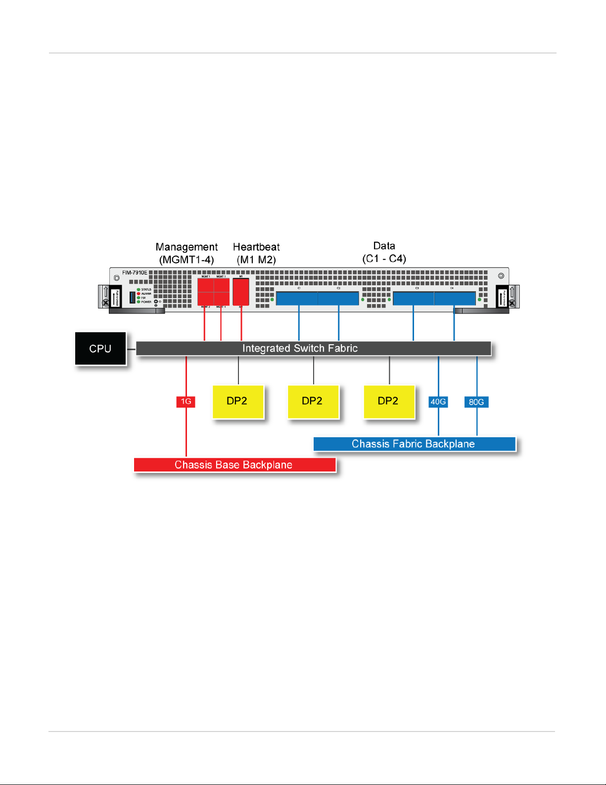
FIM-7910E interface module 22
Splitting the FIM-7910E C1 to C4 interfaces 23
FIM-7910E hardware schematic 24
FIM-7920E interface module 24
Changing the interface type and splitting the FIM-7920E C1 to C4 interfaces 25
Splitting the C1 to C4 interfaces 26
FIM-7920E hardware schematic 26
FPM-7620E processing module 27
NP6 network processors - offloading load balancing and network traffic 28
Page 4

Accelerated IPS, SSL VPN, and IPsec VPN (CP9 content processors) 30
Getting started with FortiGate-7000 31
Managing individual modules 32
Managing individual modules from the CLI 33
Connecting to module CLIs using the management module 33
Connecting to the FortiOS CLI of the FIM module in slot 1 34
Default VDOM configuration 35
Default management VDOM 35
Firmware upgrades 35
Restarting the FortiGate-7000 35
Load balancing 36
Traffic that cannot be load balanced 36
Recommended configuration for traffic that cannot be load balanced 37
Configuration synchronization 39
Failover in a standalone FortiGate-7000 39
Replacing a failed FPMor FIMmodule 39
Replacing a failed module in a standalone FortiGate-7000 chassis 39
Replacing a failed module in a FortiGate-7000 chassis inan HAcluster 40
Installing firmware on an FIM or FPM module from the BIOS using a TFTP server 41
Uploading firmware from a TFTP server to an FIMmodule 41
Uploading firmware from a TFTP server to an FPMmodule 43
Operating a FortiGate-7000 45
Failover in a standalone FortiGate-7000 45
Replacing a failed FPMor FIMmodule 45
Replacing a failed module in a standalone FortiGate-7000 chassis 45
Replacing a failed module in a FortiGate-7000 chassis inan HAcluster 46
Installing firmware on an FIM or FPM module from the BIOS using a TFTP server 46
Uploading firmware from a TFTP server to an FIMmodule 47
Uploading firmware from a TFTP server to an FPMmodule 48
IPsec VPN 51
Adding source and destination subnets to IPsec VPN phase 2 configurations 51
Example basic IPsec VPN Phase 2 configuration 51
Example multiple subnet IPsec VPN Phase 2 configuration 52
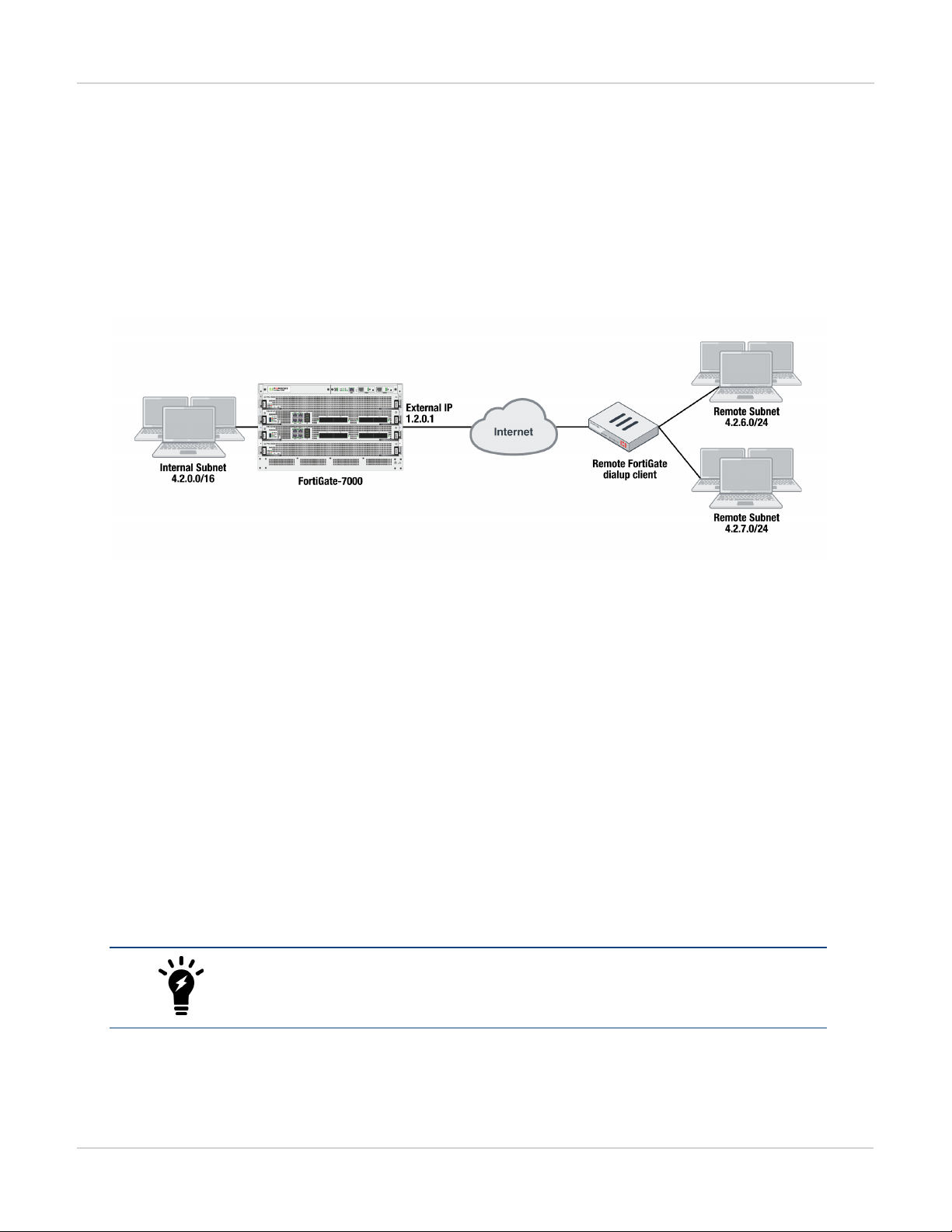
Configuring the FortiGate-7000 as a dialup IPsec VPN server 53
Example dialup IPsec VPN configuration 53
Troubleshooting 54
High Availability 57
Before you begin configuring HA 57
Connect the M1 and M2 interfaces for HA heartbeat communication 58
HA configuration 60
Setting up HA on the FIM interface modules in the first FortiGate-7000 (chassis 1) 60
HA management configuration 62
Page 5

Managing individual modules in HAmode 63
Firmware upgrade 64
Session failover (session-pickup) 64
Enabling session pickup for TCP and UDP 65
If session pickup is disabled 65
Primary unit selection and failover criteria 66
Verifying primary chassis selection 68
How link and module failures affect primary chassis selection 68
FIM module failures 70
Management link failures 70
Link failure threshold and board failover tolerance 70
Link failure threshold 70
Board failover tolerance 70
Priority and primary chassis selection 71
Override and primary chassis selection 71
FortiGate-7000 v5.4.5 special features and limitations 72
Managing the FortiGate-7000 72
Default management VDOM 72
Firewall 72
IP Multicast 72
HighAvailability 73
Shelf Manager Module 73
FortiOS features that are not supported by FortiGate-7000 v5.4.5 74
IPsec VPN tunnels terminated by the FortiGate-7000 74
SSL VPN 75
Traffic shaping and DDoS policies 75
Sniffer mode (one-arm sniffer) 75
FortiGuard Web Filtering 75
Log messages include a slot field 75
FortiOS Carrier 75
Special notice for new deployment connectivity testing 75
FortiGate-7000 v5.4.3 special features and limitations 77
Managing the FortiGate-7000 77
Default management VDOM 77
Firewall 77
Link monitoring and health checking 77
IP Multicast 78
HighAvailability 78
Shelf Manager Module 79
FortiOS features that are not supported by FortiGate-7000 v5.4.3 79
IPsec VPN tunnels terminated by the FortiGate-7000 79
More about IPsec VPN routing limitations 80
Page 6

SSL VPN 80
Authentication 80
Traffic shaping and DDoS policies 81
Sniffer mode (one-arm sniffer) 81
FortiGuard Web Filtering 81
Log messages include a slot field 81
FortiOS Carrier 81
Special notice for new deployment connectivity testing 81
FortiGate-7000 Load balancing commands 82
config load-balance flow-rule 82
Syntax 82
status {disable | enable} 83
src-interface <interface-name> [interface-name>...} 83
vlan <vlan-id> 83
ether-type {any | arp | ip | ipv4 | ipv6} 83
{src-addr-ipv4 | dst-addr-ipv4 | src-addr-ipv6 | dst-addr-ipv6} <ip-address> <netmask> 83
protocol {any | icmp | tcp | udp | igmp | sctp | gre | esp | ah | ospf | pim | vrrp} 83
{src-l4port | dst-l4port} <start>[-<end>] 83
action {forward | mirror-ingress | mirror-egress | stats | drop} 83
set mirror-interface <interface-name> 84
forward-slot {master | all | load-balance | FPM3 | FPM4 | FPM5 | FPM6} 84
priority <number> 84
comment <text> 84
config load-balance setting 84
gtp-load-balance {disable | enable} 84
max-miss-heartbeats <heartbeats> 85
max-miss-mgmt-heartbeats <heartbeats> 85
weighted-load-balance {disable | enable} 85
dp-load-distribution-method {round-robin | src-ip | dst-ip | src-dst-ip | src-ip-sport | dst-
ip-dport | src-dst-ip-sport-dport} 85
config workers 85
Page 7

Change Log
Date Change Description
December 20, 2017 Updated for FortiGate-7000 v5.4.5. New sections include What's new in for
FortiGate-7000 v5.4.5 on page 8, FortiGate-7000 v5.4.5 special features and
limitations on page 72, IPsec VPN on page 51, gtp-load-balance {disable | enable} on
page 84, and Operating a FortiGate-7000 on page 45. Also, changes to High
Availability on page 57. New section Recommended configuration for traffic that
cannot be load balanced on page 37.Additional changes and fixes throughout the
document.
Changes to Installing firmware on an FIM or FPM module from the BIOS using a
November 7, 2017
November 2, 2017 Updated with new information throughout the document including a new HA chapter.
TFTP server on page 41. Also added a note about the MGMT interface being a static
aggregate and not an LACP aggregate.
Change Log
August 30, 2017 Updated with new information throughout the document.
December 1, 2016 Initial Release
7 FortiGate-7000
Fortinet Technologies Inc.
Page 8

Introduction What's new in for FortiGate-7000 v5.4.5
Introduction
This document describes what you need to know to get started using a FortiGate-7000 product. Also included are
details about CLI commands that are specific to FortiGate-7000 products.
This FortiOS Handbook chapter contains the following sections:
FortiGate-7000 overview provides a quick overview of FortiGate-7000 components.
Getting started with FortiGate-7000 describes how to get started with managing and configuring your FortiGate-
7000 product.
FortiGate-7000 Load balancing commands describes FortiGate-7000 load balancing CLI commands.
What's new in for FortiGate-7000 v5.4.5
The following new features have been added to FortiGate-7000 v5.4.5.
M1 and M2 interfaces can use different VLANs for heartbeat traffic (408386)
The M1 and M2 interfaces can be configured to use different VLANs for HA heartbeat traffic.
The following command now configures the VLAN used by the M1 interface (default 999):
config system ha
set hbdev-vlan-id 999
end
The following new command configures the VLAN used by the M2 interface (default 1999):
config system ha
set hbdev-second-vlan-id 1999
end
GTP load balancing
GTP load balancing is supported for FortiGate-7000 configurations licensed for FortiOSCarrier. You can use the
following command to enable GTP load balancing. This command is only available after you have licensed the
FortiGate-7000 for FortiOSCarrier.
config load-balance setting
set gtp-load-balance enable
end
FSSO user authentication is synchronized
FSSO user authentication is synchronized to all FIM and FPMmodules. FSSO users are no longer required to reauthenticate when sessions are processed by a different FIM or FPM module.
FortiGate-7000
Fortinet Technologies Inc.
8
Page 9
What's new in for FortiGate-7000 v5.4.5 Introduction
HA Link failure threshold changes (422264 )
The link failure threshold is now determined based on the all FIM modules in a chassis. This means that the
chassis with the fewest active links will become the backup chassis.
FortiGate-7000s running FortiOS v5.4.5 can be configured as dialup IPsec VPN servers
The following shows how to setup a dialup IPsec VPN configuration where the FortiGate-7000 running v5.4.5 acts
as a dialup IPsec VPN server.
Configure the phase1, set type to dynamic.
config vpn ipsec phase1-interface
edit dialup-server
set type dynamic
set interface "v0020"
set peertype any
set psksecret <password>
end
Configure the phase 2, to support dialup IPsec VPN, set the destination subnet to 0.0.0.0 0.0.0.0.
config vpn ipsec phase2-interface
edit dialup-server
set phase1name dialup-server
set src-subnet 4.2.0.0 255.255.0.0
set dst-subnet 0.0.0.0 0.0.0.0
end
To configure the remote FortiGate as a dialup IPsec VPN client
The dialup IPsec VPN client should advertise its local subnet(s) using the phase 2 src-subnet option.
If there are multiple local subnets create a phase 2 for each one. Each phase 2 only
advertises one local subnet to the dialup IPsec VPN server. If more than one local
subnet is added to the phase 2, only the first one is advertised to the server.
Dialup client configuration:
config vpn ipsec phase1-interface
9 FortiGate-7000
Fortinet Technologies Inc.
Page 10

Introduction What's new in for FortiGate-7000 v5.4.5
edit "to-fgt7k"
set interface "v0020"
set peertype any
set remote-gw 1.2.0.1
set psksecret <password>
end
config vpn ipsec phase2-interface
edit "to-fgt7k"
set phase1name "to-fgt7k"
set src-subnet 4.2.6.0 255.255.255.0
set dst-subnet 4.2.0.0 255.255.0.0
next
edit "to-fgt7k-2"
set phase1name "to-fgt7k"
set src-subnet 4.2.7.0 255.255.255.0
set dst-subnet 4.2.0.0 255.255.0.0
end
FortiGate-7000
Fortinet Technologies Inc.
10
Page 11

Licenses, Device Registration, and Support FortiGate-7000 overview
FortiGate-7000 overview
A FortiGate-7000 product consists of a FortiGate-7000 series chassis (for example, the FortiGate-7040E) with
FortiGate-7000 modules installed in the chassis slots. A FortiGate-7040E chassis comes with two interface
modules (FIM) to be installed in slots 1 and 2 to provide network connections and session-aware load balancing
to two processor modules (FPM) to be installed in slots 3 and 4.
FortiGate-7000 products are sold and licensed as packages that include the chassis as well as the modules to be
included in the chassis. When you receive your FortiGate-7000 series product the chassis has to be installed in a
rack and the modules installed in the chassis. Interface modules always go in slots 1 and 2 and processor
modules in slots 3 and up.
If your FortiGate-7000 product includes two different interfaces modules, for optimal configuration you should
install the module with the lower model number in slot 1 and the module with the higher model number in slot 2.
For example, if your chassis includes a FIM-7901E and a FIM-7904E, install the FIM-7901E in chassis slot 1 and
the FIM-7904E in chassis slot 2. This applies to any combination of two different interface modules.
As an administrator, when you browse to the FortiGate-7000 management IP address you log into the interface
module in slot 1 (the primary or master interface module or FIM) to view the status of the FortiGate-7000 and
make configuration changes. The FortiOS firmware running on each module has the same configuration and
when you make configuration changes to the primary interface module, the configuration changes are
synchronized to all modules.
The same FortiOS firmware build runs on each module in the chassis. You can upgrade FortiGate-7000 firmware
by logging into the primary interface module and performing a firmware upgrade as you would for any FortiGate.
During the upgrade process the firmware of all of the modules in the chassis upgrades in one step. Firmware
upgrades should be done during a quiet time because traffic will briefly be interrupted during the upgrade
process.
Licenses, Device Registration, and Support
A FortiGate-7000 product is made up of a FortiGate-7000 series chassis, one or two FIM interface modules and
two to four FPM processor modules. The entire package is licensed and configured as a single product under the
FortiGate-7000 chassis serial number. When you receive a new FortiGate-7000 product you register it on
https://support.fortinet.com using the chassis serial number. Use the chassis serial number when requesting
support from Fortinet for the product.
All Fortinet licensing, including FortiCare Support, IPS, AntiVirus, Web Filtering, Mobile Malware, FortiClient,
FortiCloud, and additional virtual domains (VDOM) is for the entire FortiGate-7000 product and not for individual
components.
If an individual component, such as a single interface or processor fails you can RMA and replace just that
component.
11 FortiGate-7000
Fortinet Technologies Inc.
Page 12
FortiGate-7060E FortiGate-7060E front panel
FortiGate-7060E
The FortiGate-7060E is a 8U 19-inch rackmount 6-slot chassis with a 80Gbps fabric and 1Gbps base backplane
designed by Fortinet. The fabric backplane provides network data communication and the base backplane
provides management and synch communication among the chassis slots.
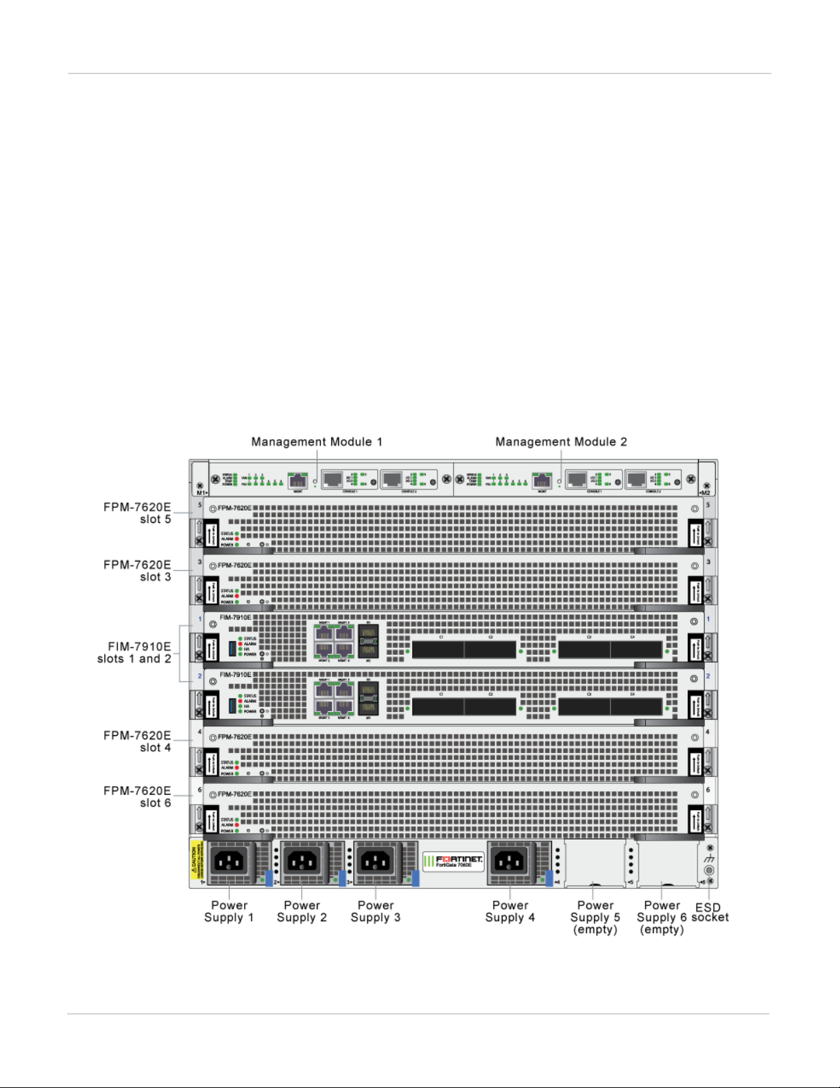
FortiGate-7060E front panel
The chassis is managed by two redundant management modules. Each module includes an Ethernet connection
as well as two switchable console ports that provide console connections to the modules in the chassis slots. The
active management module controls chassis cooling and power management and provides an interface for
managing the modules installed in the chassis.
FortiGate-7060E front panel, (example module configuration)
FortiGate-7000
Fortinet Technologies Inc.
12
Page 13
FortiGate-7060E schematic FortiGate-7060E
Power is provided to the chassis using four hot swappable 3+1 redundant 100-240 VAC, 50-60 Hz power supply
units (PSUs). You can also optionally add up to six PSUs to provide 3+3 redundancy. The FortiGate-7060E can
also be equipped with DC PSUs allowing you to connect the chassis to -48V DC power
The standard configuration of the FortiGate-7060E includes two FIM (interface) modules in chassis slots 1 and 2
and up to four FPM (processing) modules in chassis slots 3 to 6.
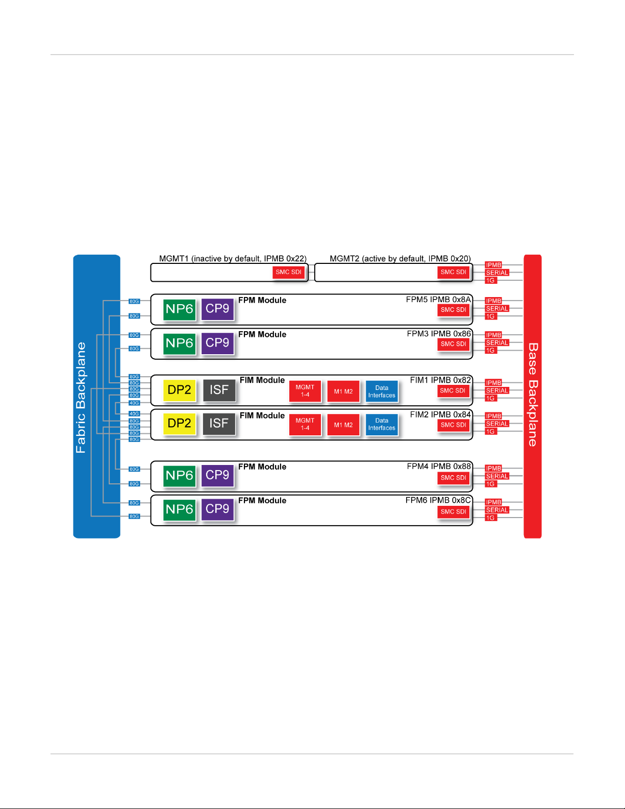
FortiGate-7060E schematic
The FortiGate-7060E chassis schematic below shows the communication channels between chassis components
including the management modules (MGMT), the FIM modules (called FIM1 and FIM2) and the FPM modules
(FPM3, FPM4, FPM5, and FPM6).
By default MGMT2 is the active management module and MGMT1 is inactive. The active management module
always has the IPMB address 0x20 and the inactive management module always has the IPMB address 0x22.
The active management module communicates with all modules in the chassis over the base backplane. Each
module, including the management modules has a Shelf Management Controller (SMC). These SMCs support
Intelligent Platform Management Bus (IPMB) communication between the active management module and the
FIM and FPM modules for storing and sharing sensor data that the management module uses to control chassis
cooling and power distribution. The base backplane also supports serial communications to allow console access
from the management module to all modules, and 1Gbps Ethernet communication for management and
heartbeat communication betweenmodules.
FIM1 and FIM2 (IPMB addresses 0x82 and 0x84) are the FIM modules in slots 1 and 2. The interfaces of these
modules connect the chassis to data networks and can be used for Ethernet management access to chassis
components. The FIM modules include DP2 processors that distribute sessions over the Integrated Switch Fabric
13 FortiGate-7000
Fortinet Technologies Inc.
Page 14
FortiGate-7060E FortiGate-7040E
(ISF) to the NP6 processors in the FPMmodules. Data sessions are communicated to the FPM modules over the
80Gbps chassis fabric backplane.
FPM03, FPM04, FPM05, and FPM06 (IPMB addresses 0x86, 0x88, 0x8A, and 0x8C) are the FPM processor
modules in slots 3 to 6. These worker modules process sessions distributed to them by the FIMmodules.
FPMmodules include NP6 processors to offload sessions from the FPM CPU and CP9 processors that accelerate
content processing.
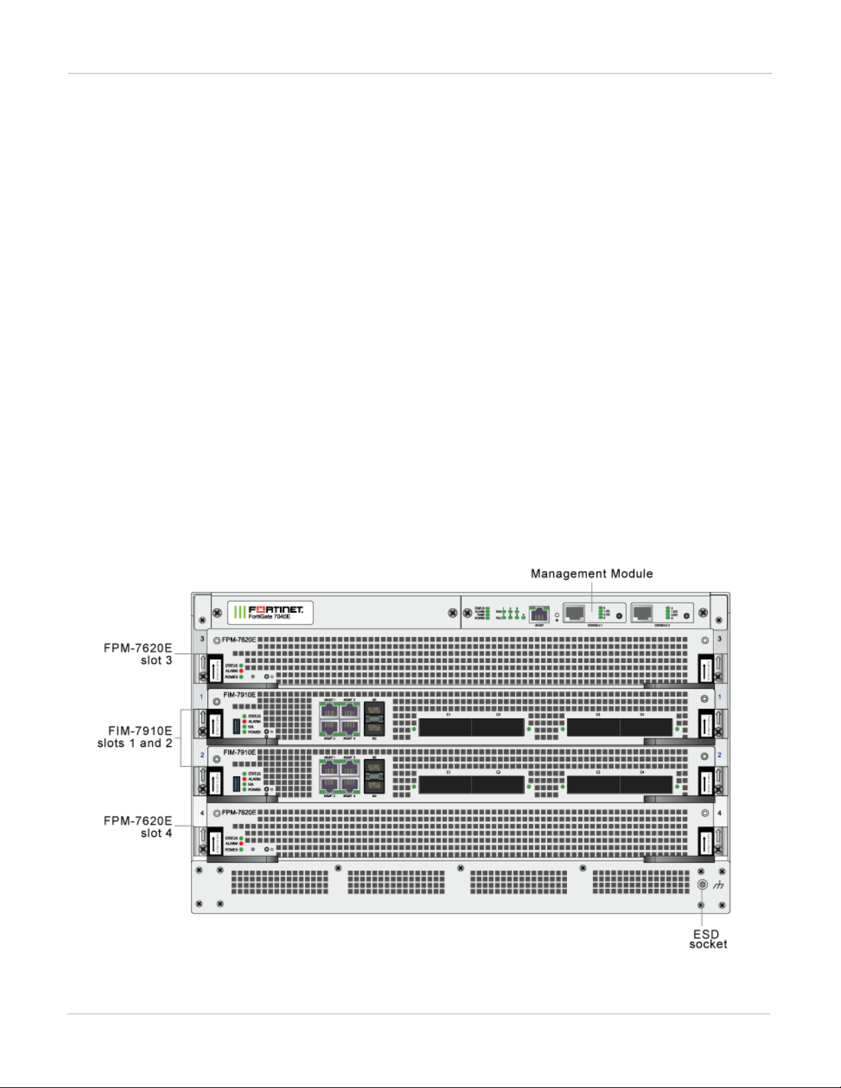
FortiGate-7040E
The FortiGate-7040E is a 6U 19-inch rackmount 4-slot chassis with a 80Gbps fabric and 1Gbps base backplane
designed by Fortinet. The fabric backplane provides network data communication and the base backplane
provides management and synch communication among the chassis slots.
FortiGate-7040E front panel
The FortiGate-7040E chassis is managed by a single management module that includes an Ethernet connection
as well as two switchable console ports that provide console connections to the modules in the chassis slots. The
management module controls chassis cooling and power management and provides an interface for managing
the modules installed in the chassis. The standard configuration of the FortiGate-7040E includes two FIM
(interface) modules in chassis slots 1 and 2 and two FPM (processing) modules in chassis slots 3 and 4.
FortiGate-7040E front panel
FortiGate-7000
Fortinet Technologies Inc.
14
Page 15
FortiGate-7030E FortiGate-7060E
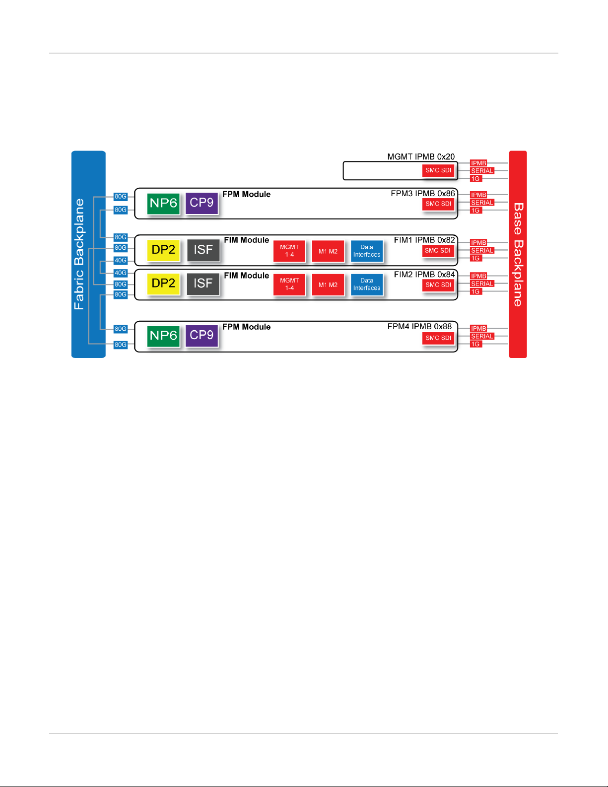
FortiGate-7040E schematic
The FortiGate-7040E chassis schematic below shows the communication channels between chassis components
including the management module (MGMT), the FIM modules (called FIM1 and FIM2) and the FPM modules
(FPM3 and FPM4).
The management module (MGMT, with IPMB address 0x20) communicates with all modules in the chassis over
the base backplane. Each module, including the management module includes a Shelf Management Controller
(SMC). These SMCs support Intelligent Platform Management Bus (IPMB) communication between the
management module and the FIM and FPM modules for storing and sharing sensor data that the management
module uses to control chassis cooling and power distribution. The base backplane also supports serial
communications to allow console access from the management module to all modules, and 1Gbps Ethernet
communication for management and heartbeat communication betweenmodules.
FIM1 and FIM2 (IPMB addresses 0x82 and 0x84) are the FIM modules in slots 1 and 2. The interfaces of these
modules connect the chassis to data networks and can be used for Ethernet management access to chassis
components. The FIM modules include DP2 processors that distribute sessions over the Integrated Switch Fabric
(ISF) to the NP6 processors in the FPMmodules. Data sessions are communicated to the FPM modules over the
80Gbps chassis fabric backplane.
FPM3 and FPM4 (IPMB addresses 0x86 and 0x88) are the FPM processor modules in slots 3 and 4. These
worker modules process sessions distributed to them by the FIMmodules. FPMmodules include NP6 processors
to offload sessions from the FPM CPU and CP9 processors that accelerate content processing.
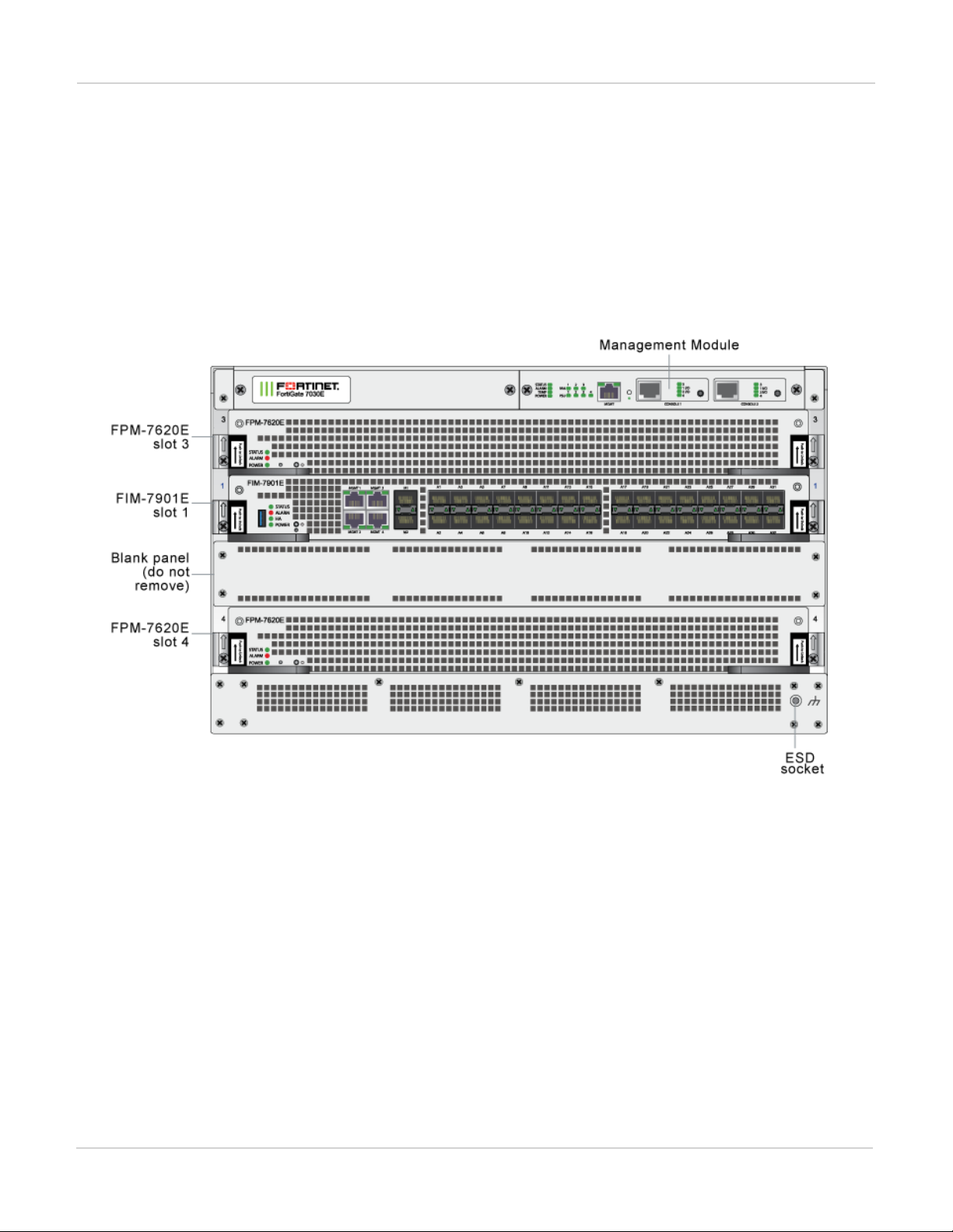
FortiGate-7030E
The FortiGate-7030E is a 6U 19-inch rackmount 3-slot chassis with a 80Gbps fabric and 1Gbps base backplane
designed by Fortinet. The fabric backplane provides network data communication and the base backplane
provides management and synch communication among the chassis slots.
15 FortiGate-7000
Fortinet Technologies Inc.
Page 16
FortiGate-7060E FortiGate-7030E
FortiGate-7030E front panel
The FortiGate-7030E chassis is managed by a single management module that includes an Ethernet connection
as well as two switchable console ports that provide console connections to the modules in the chassis slots. The
management module controls chassis cooling and power management and provides an interface for managing
the modules installed in the chassis. The standard configuration of the FortiGate-7030E includes one FIM
(interface) module in chassis slot 1 and two FPM (processing) modules in chassis slots 3 and 4. The front panel
also includes a sealed blank panel. Breaking the seal or removing the panel voids your FortiGate-7030E warranty.
FortiGate-7030E front panel (example module configuration)
(missing or bad snippet)
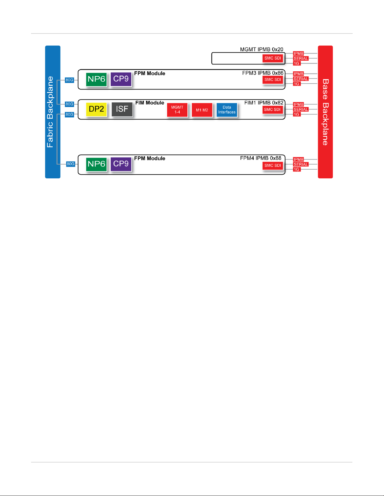
FortiGate-7030E schematic
The FortiGate-7030E chassis schematic below shows the communication channels between chassis components
including the management module (MGMT), the FIM module (called FIM1) and the FPM modules (FPM3 and
FPM4).
FortiGate-7000
Fortinet Technologies Inc.
16
Page 17
FortiGate-7030E FortiGate-7060E
The management module (MGMT, with IPMB address 0x20) communicates with all modules in the chassis over
the base backplane. Each module, including the management module includes a Shelf Management Controller
(SMC). These SMCs support Intelligent Platform Management Bus (IPMB) communication between the
management module and the FIM and FPM modules for storing and sharing sensor data that the management
module uses to control chassis cooling and power distribution. The base backplane also supports serial
communications to allow console access from the management module to all modules, and 1Gbps Ethernet
communication for management and heartbeat communication betweenmodules.
FIM1 (IPMB address 0x82) is the FIM module in slot 1. The interfaces of this module connect the chassis to data
networks and can be used for Ethernet management access to chassis components. The FIM module include
DP2 processors that distribute sessions over the Integrated Switch Fabric (ISF) to the NP6 processors in the
FPMmodules. Data sessions are communicated to the FPM modules over the 80Gbps chassis fabric backplane.
FPM3 and FPM4 (IPMB addresses 0x86 and 0x88) are the FPM processor modules in slots 3 and 4. These
worker modules process sessions distributed to them by the FIMmodule. FPMmodules include NP6 processors
to offload sessions from the FPM CPU and CP9 processors that accelerate content processing.
17 FortiGate-7000
Fortinet Technologies Inc.
Page 18
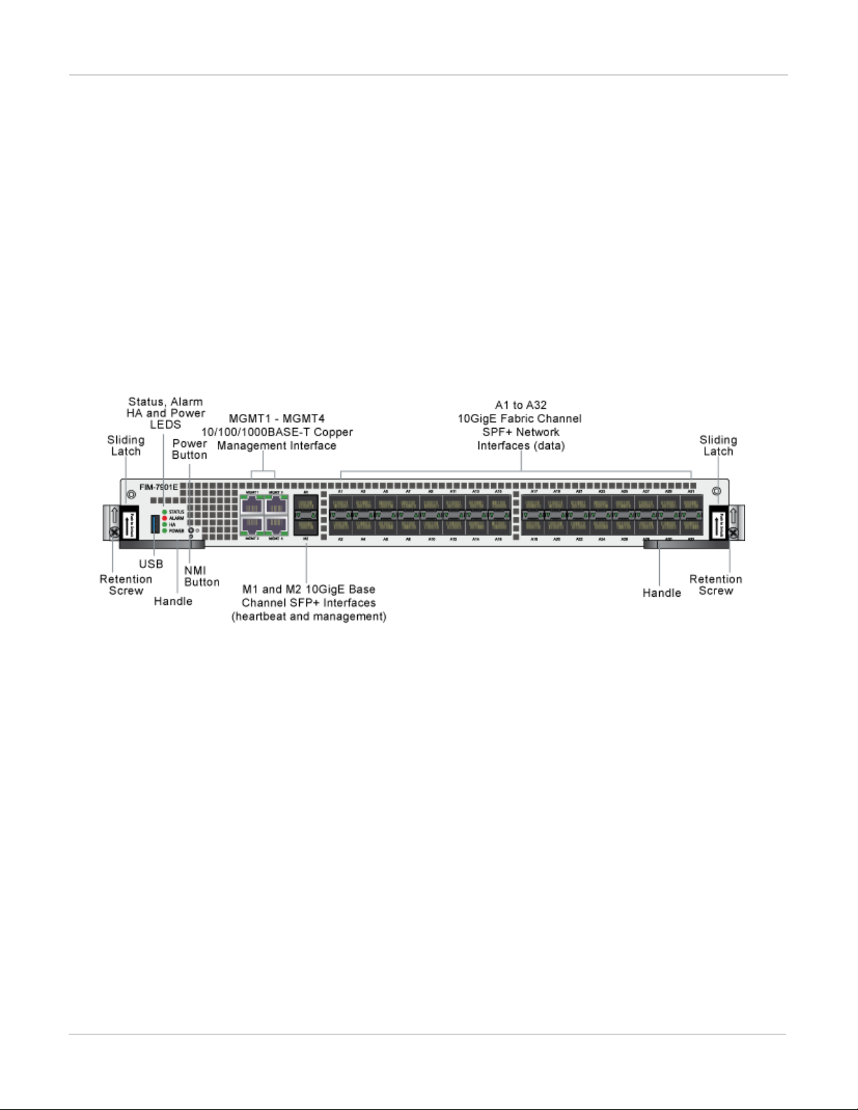
FIM-7901E interface module FortiGate-7030E
FIM-7901E interface module
The FIM-7901E interface module is a hot swappable module that provides data, management and session
sync/heartbeat interfaces, base backplane switching and fabric backplane session-aware load balancing for a
FortiGate-7000 chassis. The FIM-7901E includes an integrated switch fabric and DP2 processors to load balance
millions of data sessions over the chassis fabric backplane to FPM processor modules.
The FIM-7901E can be installed in any FortiGate-7000 series chassis in hub/switch slots 1 and 2. The FIM-7901E
provides thirty-two 10GigE small form-factor pluggable plus (SPF+) interfaces for a FortiGate-7000 chassis.
You can also install FIM-7901Es in a second chassis and operate the chassis in HA mode with another set of
processor modules to provide chassis failover protection.
FIM-7901E front panel
The FIM-7901E includes the following hardware features:
l Thirty-two front panel 10GigE SFP+ fabric channel interfaces (A1 to A32). These interfaces are connected to
10Gbps networks to distribute sessions to the FPM processor modules installed in chassis slots 3 and up. These
interfaces can also be configured to operate as Gigabit Ethernet interfaces using SFP transceivers. These
interfaces also support creating link aggregation groups (LAGs) that can include interfaces from both FIM-7901Es.
l Two front panel 10GigE SFP+ interfaces (M1 and M2) that connect to the base backplane channel. These
interfaces are used for heartbeat, session sync, and management communication between FIM-7901Es in different
chassis. These interfaces can also be configured to operate as Gigabit Ethernet interfaces using SFP transceivers,
but should not normally be changed. If you use switches to connect these interfaces, the switch ports should be
able to accept packets with a maximum frame size of at least 1526. The M1 and M2 interfaces need to be on
different broadcast domains. If M1 and M2 are connected to the same switch, Q-in-Q must be enabled on the
switch.
l Four 10/100/1000BASE-T out of band management Ethernet interfaces (MGMT1 to MGMT4).
l One 80Gbps fabric backplane channel for traffic distribution with each FPM module installed in the same chassis as
the FIM-7901E.
l One 1Gbps base backplane channel for base backplane with each FPM module installed in the same chassis as the
FIM-7901E.
l One 40Gbps fabric backplane channel for fabric backplane communication with the other FIM-7901E in the chassis.
FortiGate-7000
Fortinet Technologies Inc.
18
Page 19
FortiGate-7030E FIM-7901E interface module
l One 1Gbps base backplane channel for base backplane communication with the other FIM-7901E in the chassis.
l On-board DP2 processors and an integrated switch fabric to provide high-capacity session-aware load balancing.
l One front panel USB port.
l Power button.
l NMIswitch (for troubleshooting as recommended by Fortinet Support).
l Mounting hardware.
l LED status indicators.
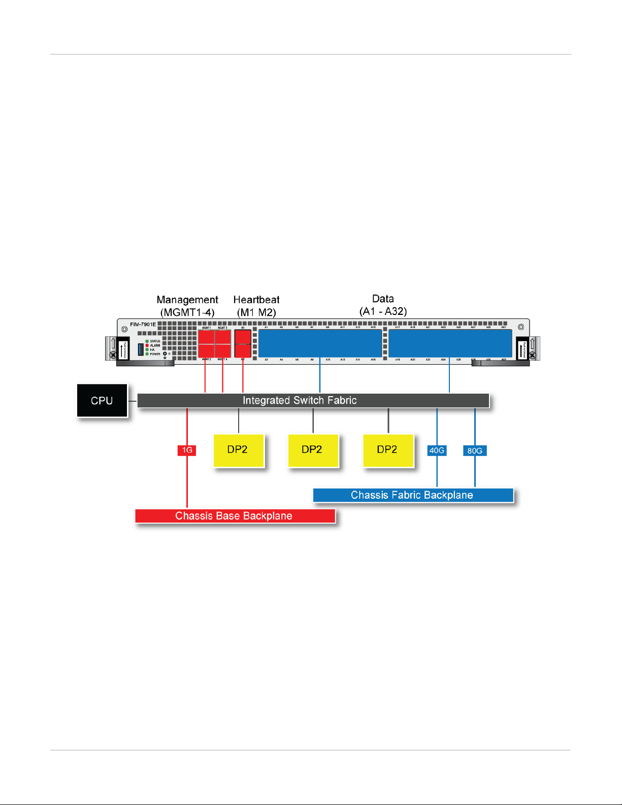
FIM-7901E schematic
The FIM-7901E includes an integrated switch fabric (ISF) that connects the front panel interfaces to the DP2
session-aware load balancers and to the chassis backplanes. The ISFalso allows the DP2 processors to
distribute sessions amoung all NP6 processors on the FPMmodules in the same chassis.
FIM-7901E schematic
19 FortiGate-7000
Fortinet Technologies Inc.
Page 20
FIM-7904E interface module FortiGate-7030E
FIM-7904E interface module
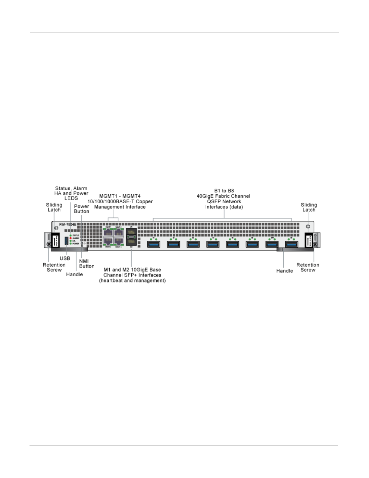
The FIM-7904E interface module is a hot swappable module that provides data, management and session
sync/heartbeat interfaces, base backplane switching and fabric backplane session-aware load balancing for a
FortiGate-7000 series chassis. The FIM-7904E includes an integrated switch fabric and DP2 processors to load
balance millions of data sessions over the chassis fabric backplane to FPM processor modules.
The FIM-7904E can be installed in any FortiGate-7000 series chassis in hub/switch slots 1 and 2. The FIM-7904E
provides four Quad Small Form-factor Pluggable plus (QSFP+) interfaces for a FortiGate-7000 chassis. Using a
40GBASE-SR10 multimode QSFP+ transceiver, each QSFP+ interface can also be split into four 10GBASE-SR
interfaces.
You can also install FIM-7904Es in a second chassis and operate the chassis in HA mode with another set of
processor modules to provide chassis failover protection.
FIM-7904E front panel
The FIM-7904E includes the following hardware features:
l Eight front panel 40GigE QSFP+ fabric channel interfaces (B1 to B8). These interfaces are connected to 40Gbps
networks to distribute sessions to the FPM processor modules installed in chassis slots 3 and up. Using 40GBASESR10 multimode QSFP+ transceivers, each QSFP+ interface can also be split into four 10GBASE-SR interfaces.
These interfaces also support creating link aggregation groups (LAGs) that can include interfaces from both FIM7904Es.
l Two front panel 10GigE SFP+ interfaces (M1 and M2) that connect to the base backplane channel. These
interfaces are used for heartbeat, session sync, and management communication between FIM-7904Es in different
chassis. These interfaces can also be configured to operate as Gigabit Ethernet interfaces using SFP transceivers,
but should not normally be changed. If you use switches to connect these interfaces, the switch ports should be
able to accept packets with a maximum frame size of at least 1526. The M1 and M2 interfaces need to be on
different broadcast domains. If M1 and M2 are connected to the same switch, Q-in-Q must be enabled on the
switch.
l Four 10/100/10000BASE-T out of band management Ethernet interfaces (MGMT1 to MGMT4).
l One 80Gbps fabric backplane channel for traffic distribution with each FPM module installed in the same chassis as
the FIM-7904E.
FortiGate-7000
Fortinet Technologies Inc.
20
Page 21

FortiGate-7030E FIM-7904E interface module
l One 1Gbps base backplane channel for base backplane with each FPM module installed in the same chassis as the
FIM-7904E.
l One 40Gbps fabric backplane channel for fabric backplane communication with the other FIM-7904E in the chassis.
l One 1Gbps base backplane channel for base backplane communication with the other FIM-7904E in the chassis.
l On-board DP2 processors and an integrated switch fabric to provide high-capacity session-aware load balancing.
l One front panel USB port.
l Power button.
l NMIswitch (for troubleshooting as recommended by Fortinet Support).
l Mounting hardware.
l LED status indicators.
Splitting the FIM-7904E B1 to B8 interfaces
Each 40GE interface (B1 to B8) on the FIM-7904Es in slot 1 and slot 2 of a FortiGate-7000 system can be split
into 4x10GBE interfaces. You split these interfaces after the FIM-7904Es are installed in your FortiGate-7000
system and the system us up and running. You can split the interfaces of the FIM-7904Es in slot 1 and slot 2 at
the same time by entering a single CLI command. Splitting the interfaces requires a system reboot so Fortinet
recommends that you split multiple interfaces at the same time according to your requirements to avoid traffic
disruption.
For example, to split the B1 interface of the FIM-7904E in slot 1 (this interface is named 1-B1) and the B1 and B4
interfaces of the FIM-7904E in slot 2 (these interfaces are named 2-B1 and 2-B4) connect to the CLI of your
FortiGate-7000 system using the management IP and enter the following command:
config system global
set split-port 1-B1 2-B1 2-B4
end
After you enter the command, the FortiGate-7000 reboots and when it comes up:
l The 1-B1 interface will no longer be available. Instead the 1-B1/1, 1-B1/2, 1-B1/3, and 1-B1/4 interfaces will be
available.
l The 2-B1 interface will no longer be available. Instead the 2-B1/1, 2-B1/2, 2-B1/3, and 2-B1/4 interfaces will be
available.
l The 2-B4 interface will no longer be available. Instead the 2-B4/1, 2-B4/2, 2-B4/3, and 2-B4/4 interfaces will be
available.
You can now connect breakout cables to these interfaces and configure traffic between them just like any other
FortiGate interface.
FIM-7904E hardware schematic
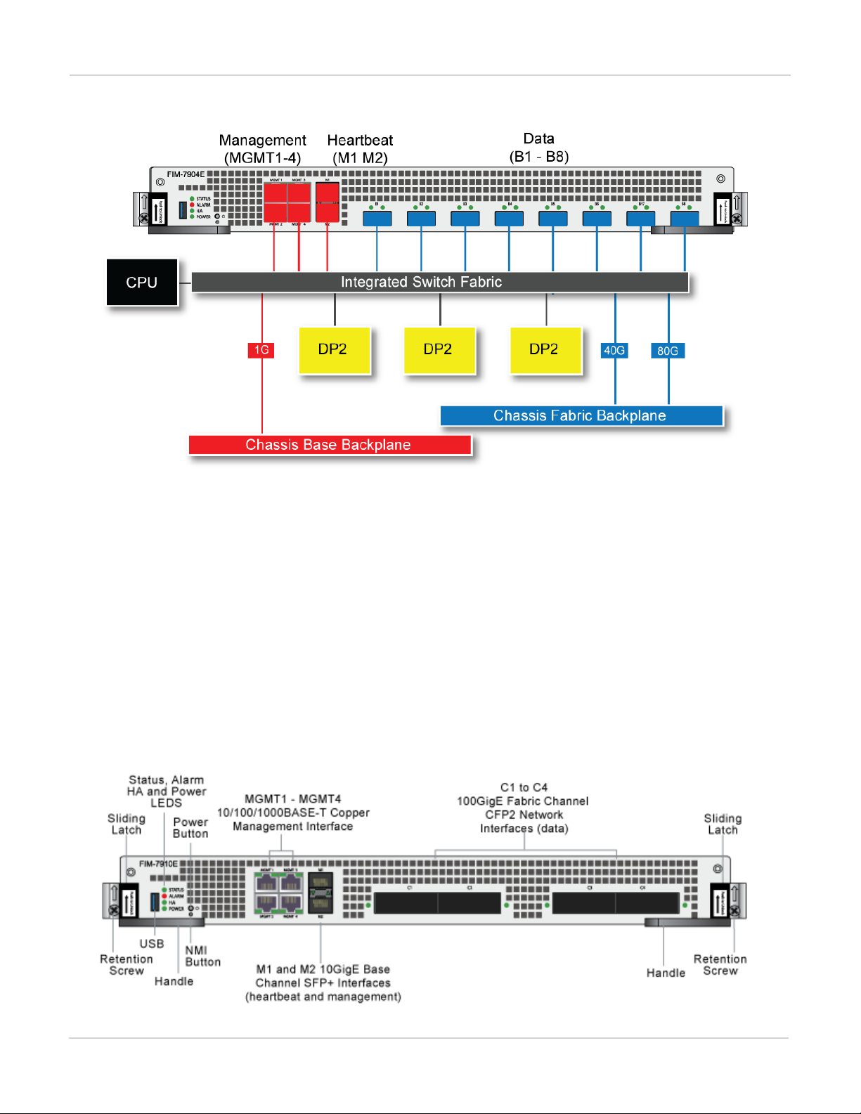
The FIM-7904E includes an integrated switch fabric (ISF) that connects the front panel interfaces to the DP2
session-aware load balancers and to the chassis backplanes. The ISFalso allows the DP2 processors to
distribute sessions amoung all NP6 processors on the FPMmodules in the same chassis.
21 FortiGate-7000
Fortinet Technologies Inc.
Page 22
FIM-7904E interface module FIM-7910E interface module
FIM-7904E hardware architecture
FIM-7910E interface module
The FIM-7910E interface module is a hot swappable module that provides data, management and session
sync/heartbeat interfaces, base backplane switching and fabric backplane session-aware load balancing for a
FortiGate-7000 series chassis. The FIM-7910E includes an integrated switch fabric and DP2 processors to load
balance millions of data sessions over the chassis fabric backplane to FPM processor modules.
The FIM-7910E can be installed in any FortiGate-7000 series chassis in hub/switch slots 1 and 2. The FIM-7910E
provides four C form-factor pluggable 2 (CFP2) interfaces for a FortiGate-7000 chassis. Using a 100GBASESR10 multimode CFP2 transceiver, each CFP2 interface can also be split into ten 10GBASE-SR interfaces.
FIM-7910E front panel
FortiGate-7000
Fortinet Technologies Inc.
22
Page 23

FIM-7910E interface module FIM-7904E interface module
The FIM-7910E includes the following hardware features:
l Four front panel 100GigE CFP2 fabric channel interfaces (C1 to C4). These interfaces are connected to 100Gbps
networks to distribute sessions to the FPM processor modules installed in chassis slots 3 and up. Using 100GBASESR10 multimode CFP2 transceivers, each CFP2 interface can also be split into ten 10GBASE-SR interfaces. These
interfaces also support creating link aggregation groups (LAGs) that can include interfaces from both FIM-7910Es.
l Two front panel 10GigE SFP+ interfaces (M1 and M2) that connect to the base backplane channel. These
interfaces are used for heartbeat, session sync, and management communication between FIM-7910Es in different
chassis. These interfaces can also be configured to operate as Gigabit Ethernet interfaces using SFP transceivers,
but should not normally be changed. If you use switches to connect these interfaces, the switch ports should be
able to accept packets with a maximum frame size of at least 1526. The M1 and M2 interfaces need to be on
different broadcast domains. If M1 and M2 are connected to the same switch, Q-in-Q must be enabled on the
switch.
l Four 10/100/1000BASE-T out of band management Ethernet interfaces (MGMT1 to MGMT4).
l One 80Gbps fabric backplane channel for traffic distribution with each FPM module installed in the same chassis as
the FIM-7910E.
l One 1Gbps base backplane channel for base backplane with each FPM module installed in the same chassis as the
FIM-7910E.
l One 40Gbps fabric backplane channel for fabric backplane communication with the other FIM-7910E in the chassis.
l One 1Gbps base backplane channel for base backplane communication with the other FIM-7910E in the chassis.
l On-board DP2 processors and an integrated switch fabric to provide high-capacity session-aware load balancing.
l One front panel USB port.
l Power button.
l NMIswitch (for troubleshooting as recommended by Fortinet Support).
l Mounting hardware.
l LED status indicators.
Splitting the FIM-7910E C1 to C4 interfaces
Each 100GE interface (C1 to C4) on the FIM-7910Es in slot 1 and slot 2 of a FortiGate-7000 system can be split
into 10 x 10GBE interfaces. You split these interfaces after the FIM-7910Es are installed in your FortiGate-7000
system and the system us up and running. You can split the interfaces of the FIM-7910Es in slot 1 and slot 2 at
the same time by entering a single CLI command. Splitting the interfaces requires a system reboot so Fortinet
recommends that you split multiple interfaces at the same time according to your requirements to avoid traffic
disruption.
For example, to split the C1 interface of the FIM-7910E in slot 1 (this interface is named 1-C1) and the C1 and C4
interfaces of the FIM-7910E in slot 2 (these interfaces are named 2-C1 and 2-C4) connect to the CLI of your
FortiGate-7000 system using the management IP and enter the following command:
config system global
set split-port 1-C1 2-C1 2-C4
end
After you enter the command, the FortiGate-7000 reboots and when it comes up:
l The 1-C1 interface will no longer be available. Instead the 1-C1/1, 1-C1/2, ..., and 1-C1/10 interfaces will be
available.
l The 2-C1 interface will no longer be available. Instead the 2-C1/1, 2-C1/2, ..., and 2-C1/10 interfaces will be
available.
23 FortiGate-7000
Fortinet Technologies Inc.
Page 24
FIM-7904E interface module FIM-7920E interface module
l The 2-C4 interface will no longer be available. Instead the 2-C4/1, 2-C4/2, ..., and 2-C4/10 interfaces will be
available.
You can now connect breakout cables to these interfaces and configure traffic between them just like any other
FortiGate interface.
FIM-7910E hardware schematic
The FIM-7910E includes an integrated switch fabric (ISF) that connects the front panel interfaces to the DP2
session-aware load balancers and to the chassis backplanes. The ISFalso allows the DP2 processors to
distribute sessions amoung all NP6 processors on the FPMmodules in the same chassis.
FIM-7910E hardware schematic
FIM-7920E interface module
The FIM-7920E interface module is a hot swappable module that provides data, management and session
sync/heartbeat interfaces, base backplane switching and fabric backplane session-aware load balancing for a
FortiGate-7000 series chassis. The FIM-7920E includes an integrated switch fabric and DP2 processors to load
balance millions of data sessions over the chassis fabric backplane to FPM processor modules.
The FIM-7920E can be installed in any FortiGate-7000 series chassis in hub/switch slots 1 or 2. The FIM-7920E
provides four Quad Small Form-factor Pluggable 28 (QSFP28) 100GigE interfaces for a FortiGate-7000 chassis.
Using a 100GBASE-SR4 QSFP28 or 40GBASE-SR4 QSFP+ transceiver, each QSFP28 interface can also be split
into four 10GBASE-SR interfaces.
You can also install FIM-7920Es in a second chassis and operate the chassis in HA mode with another set of
processor modules to provide chassis failover protection.
FortiGate-7000
Fortinet Technologies Inc.
24
Page 25
FIM-7920E interface module FIM-7904E interface module
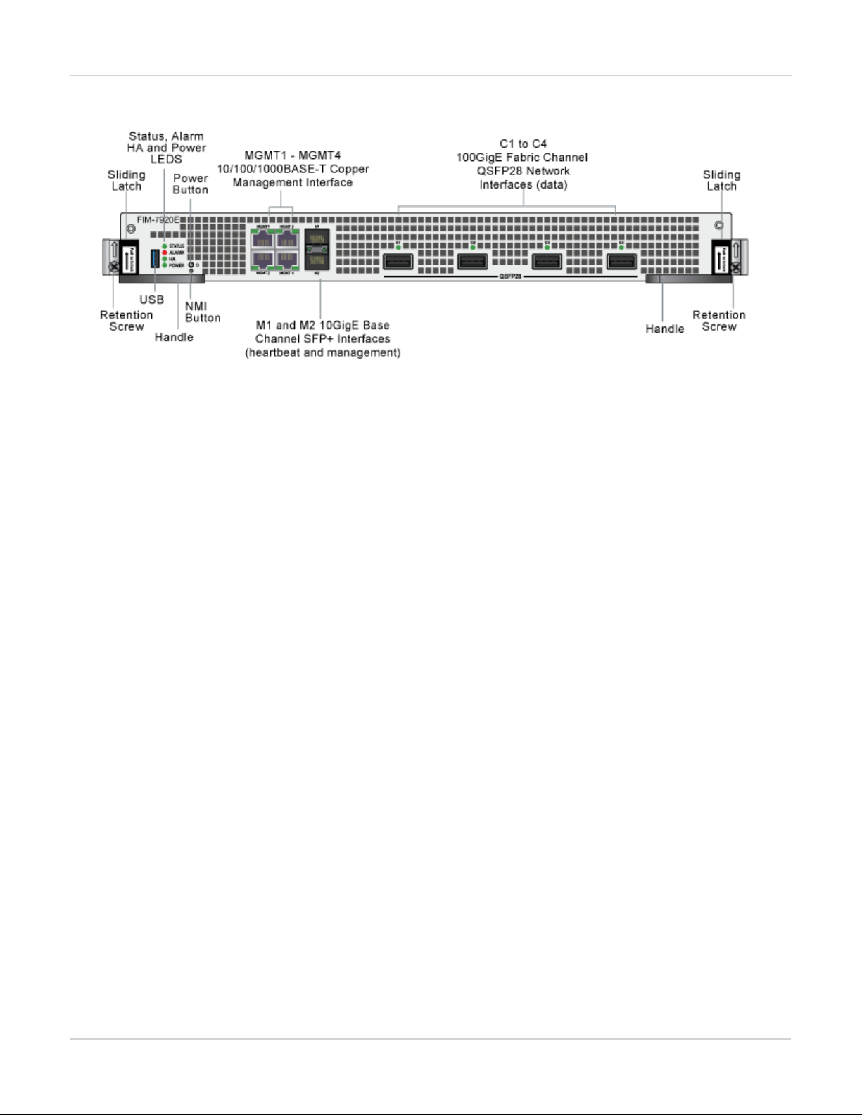
FIM-7920E front panel
The FIM-7920E includes the following hardware features:
l Four front panel 100GigE QSFP28 fabric channel interfaces (C1 to C4). These interfaces are connected to
100Gbps networks to distribute sessions to the FPM processor modules installed in chassis slots 3 and up. Using a
100GBASE-SR4 QSFP28 or 40GBASE-SR4 QSFP+ transceiver, each QSFP28 interface can also be split into four
10GBASE-SR interfaces. These interfaces also support creating link aggregation groups (LAGs) that can include
interfaces from both FIM-7920Es.
l Two front panel 10GigE SFP+ interfaces (M1 and M2) that connect to the base backplane channel. These
interfaces are used for heartbeat, session sync, and management communication between FIM-7920Es in different
chassis. These interfaces can also be configured to operate as Gigabit Ethernet interfaces using SFP transceivers,
but should not normally be changed. If you use switches to connect these interfaces, the switch ports should be
able to accept packets with a maximum frame size of at least 1526. The M1 and M2 interfaces need to be on
different broadcast domains. If M1 and M2 are connected to the same switch, Q-in-Q must be enabled on the
switch.
l Four 10/100/1000BASE-T out of band management Ethernet interfaces (MGMT1 to MGMT4).
l One 80Gbps fabric backplane channel for traffic distribution with each FPM module installed in the same chassis as
the FIM-7920E.
l One 1Gbps base backplane channel for base backplane with each FPM module installed in the same chassis as the
FIM-7920E.
l One 40Gbps fabric backplane channel for fabric backplane communication with the other FIM-7920E in the chassis.
l One 1Gbps base backplane channel for base backplane communication with the other FIM-7920E in the chassis.
l On-board DP2 processors and an integrated switch fabric to provide high-capacity session-aware load balancing.
l One front panel USB port.
l Power button.
l NMIswitch (for troubleshooting as recommended by Fortinet Support).
l Mounting hardware.
l LED status indicators.
Changing the interface type and splitting the FIM-7920E C1 to C4 interfaces
By default, the FIM-7920E C1 to C4 interfaces are configured as 100GE QSFP28 interfaces. You can use the
following command to convert them to 40GE QSFP+ interfaces. Once converted, you can use the other
command below to split them into four 10GBASE-SR interfaces.
25 FortiGate-7000
Fortinet Technologies Inc.
Page 26

FIM-7904E interface module FIM-7920E hardware schematic
Changing the interface type
For example, to change the interface type of the C1 interface of the FIM-7920E in slot 1 to 40GE QSFP+ connect
to the CLI of your FortiGate-7000 system using the management IP and enter the following command:
config system global
set qsfp28-40g-port 1-C1
end
The FortiGate-7000 system reboots and when it starts up interface C1 of the FIM-7920E in slot 1 is operating as
a 40GE QSFP+ interface .
To change the interface type of the C3 and C4 ports of the FIM-7920E in slot 2 to 40GE QSFP+ enter the
following command:
config system global
set qsfp28-40g-port 2-C3 2-C4
end
The FortiGate-7000 system reboots and when it starts up interfaces C3 and C4 of the FIM-7920E in slot 2 are
operating as a 40GE QSFP+ interfaces.
Splitting the C1 to C4 interfaces
Each 40GE interface (C1 to C4) on the FIM-7920Es in slot 1 and slot 2 of a FortiGate-7000 system can be split
into 4 x 10GBE interfaces. You split these interfaces after the FIM-7920Es are installed in your FortiGate-7000
system and the system us up and running. You can split the interfaces of the FIM-7920Es in slot 1 and slot 2 at
the same time by entering a single CLI command. Splitting the interfaces requires a system reboot so Fortinet
recommends that you split multiple interfaces at the same time according to your requirements to avoid traffic
disruption.
For example, to split the C1 interface of the FIM-7920E in slot 1 (this interface is named 1-C1) and the C1 and C4
interfaces of the FIM-7920E in slot 2 (these interfaces are named 2-C1 and 2-C4) connect to the CLI of your
FortiGate-7000 system using the management IP and enter the following command:
config system global
set split-port 1-C1 2-C1 2-C4
end
After you enter the command, the FortiGate-7000 reboots and when it comes up:
l The 1-C1 interface will no longer be available. Instead the 1-C1/1, 1-C1/2, 1-C1/3, and 1-C1/4 interfaces will be
available.
l The 2-C1 interface will no longer be available. Instead the 2-C1/1, 2-C1/2, 2-C1/3, and 2-C1/4 interfaces will be
available.
l The 2-C4 interface will no longer be available. Instead the 2-C4/1, 2-C4/2, 2-C4/3, and 2-C4/4 interfaces will be
available.
You can now connect breakout cables to these interfaces and configure traffic between them just like any other
FortiGate interface.
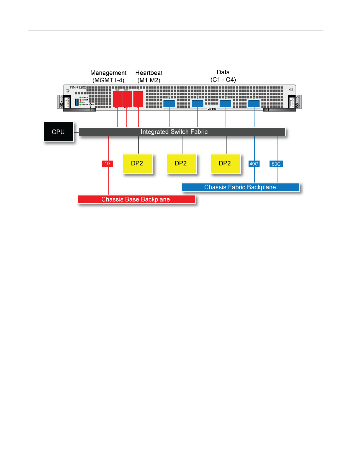
FIM-7920E hardware schematic
The FIM-7920E includes an integrated switch fabric (ISF) that connects the front panel interfaces to the DP2
session-aware load balancers and to the chassis backplanes. The ISFalso allows the DP2 processors to
FortiGate-7000
Fortinet Technologies Inc.
26
Page 27
FPM-7620E processing module FIM-7904E interface module
distribute sessions among all NP6 processors on the FPMmodules in the same chassis.
FIM-7920E hardware schematic
FPM-7620E processing module
The FPM-7620E processing module is a high-performance worker module that processes sessions load balanced
to it by FortiGate-7000 series interface (FIM) modules over the chassis fabric backplane. The FPM-7620E can be
installed in any FortiGate-7000 series chassis in slots 3 and up.
The FPM-7620E includes two 80Gbps connections to the chassis fabric backplane and two 1Gbps connections to
the base backplane. The FPM-7620E processes sessions using a dual CPU configuration, accelerates network
traffic processing with 4 NP6 processors and accelerates content processing with 8 CP9 processors. The NP6
network processors are connected by the FIM switch fabric so all supported traffic types can be fast path
accelerated by the NP6 processors.
The FPM-7620E includes the following hardware features:
l Two 80Gbps fabric backplane channels for load balanced sessions from the FIM modules installed in the chassis.
l Two 1Gbps base backplane channels for management, heartbeat and session sync communication.
l Dual CPUs for high performance operation.
l Four NP6 processors to offload network processing from the CPUs.
l Eight CP9 processors to offload content processing and SSL and IPsec encryption from the CPUs.
27 FortiGate-7000
Fortinet Technologies Inc.
Page 28

FIM-7904E interface module FPM-7620E processing module
FPM-7620E front panel
l Power button.
l NMI switch (for troubleshooting as recommended by Fortinet Support).
l Mounting hardware.
l LED status indicators.
NP6 network processors - offloading load balancing and network traffic
The four FPM-7620E NP6 network processors combined with theFIM module integrated switch fabric (ISF)
provide hardware acceleration by offloading load balancing from the FPM-7620E CPUs. The result is enhanced
network performance provided by the NP6 processors plus the network processing load is removed from the CPU.
The NP6 processor can also handle some CPU intensive tasks, like IPsec VPN encryption/decryption. Because of
the integrated switch fabric, all sessions are fast-pathed and accelerated.
FortiGate-7000
Fortinet Technologies Inc.
28
Page 29

FPM-7620E processing module FIM-7904E interface module
FPM-7620E hardware architecture
29 FortiGate-7000
Fortinet Technologies Inc.
Page 30

FIM-7904E interface module Accelerated IPS, SSL VPN, and IPsec VPN (CP9 content processors)
Accelerated IPS, SSL VPN, and IPsec VPN (CP9 content processors)
The FPM-7620E includes eight CP9 processors that provide the following performance enhancements:
l Flow-based inspection (IPS, application control etc.) pattern matching acceleration with over 10Gbps throughput
l IPS pre-scan
l IPS signature correlation
l Full match processors
l High performance VPN bulk data engine
l IPsec and SSL/TLS protocol processor
l DES/3DES/AES128/192/256 in accordance with FIPS46-3/FIPS81/FIPS197
l MD5/SHA-1/SHA256/384/512-96/128/192/256 with RFC1321 and FIPS180
l HMAC in accordance with RFC2104/2403/2404 and FIPS198
l ESN mode
l GCM support for NSA "Suite B" (RFC6379/RFC6460) including GCM-128/256; GMAC-128/256
l Key Exchange Processor that supports high performance IKE and RSA computation
l Public key exponentiation engine with hardware CRT support
l Primary checking for RSA key generation
l Handshake accelerator with automatic key material generation
l True Random Number generator
l Elliptic Curve support for NSA "Suite B"
l Sub public key engine (PKCE) to support up to 4096 bit operation directly (4k for DH and 8k for RSA with CRT)
l DLP fingerprint support
l TTTD (Two-Thresholds-Two-Divisors) content chunking
l Two thresholds and two divisors are configurable
FortiGate-7000
Fortinet Technologies Inc.
30
Page 31

Accelerated IPS, SSL VPN, and IPsec VPN (CP9 content processors) Getting started with FortiGate-7000
Getting started with FortiGate-7000
Once you have installed your FortiGate-7000 chassis in a rack and installed FIM interface modules and FPM
processing modules in it you can power on the chassis and all modules in the chassis will power up.
Whenever a chassis is first powered on, it takes about 5 minutes for all modules to start up and become
completely initialized and synchronized. During this time the chassis will not allow traffic to pass through and you
may not be able to log into the GUI, or if you manage to log in the session could time out as the FortiGate-7000
continues negotiating.
Review the chassis and module front panel LEDs to verify that everything is operating normally. Wait until the
chassis has complete started up and synchronized before making configuration changes. You can use the
diagnose system ha status command to confirm that the FortiGate-7000 is completely initialized. If the
output from entering this command hasn't changed after checking for a few minutes you can assume that the
system has initialized. You don't normally have to confirm that the system has initialized, but this diagnose
command is available if needed.
You can configure and manage the FortiGate-7000 by connecting an Ethernet cable to one of the MGMT1 to
MGMT4 interfaces of one of the FIM interface modules in the chassis. By default the MGMT1 to MGMT4
interfaces of both interface modules have been added to a static 802.3 aggregate interface called mgmt with a
default IPaddress of 192.168.1.99.
LACPis not supported for the mgmt aggregate interface. The MGMT1 to MGMT4
interfaces are in a static aggregate interface.
You can connect to any of the MGMT1 to MGMT4 interfaces to create a management connection to the
FortiGate-7000. You can also set up a switch with a static 802.3 aggregate interface and connect the switch ports
in the aggregate interface to multiple MGMT1 to MGMT4 interfaces to set up redundant management
connections to the FortiGate-7000.
Connect to the GUI by browsing to https://192.168.1.99. Log into the GUI using the admin account with no
password. Connect to the CLI by using SSH to connect to 192.168.1.99. You may have to enable SSH
administrative access for the mgmt interface before you can connect to the CLI.
For security reasons you should add a password to the admin account before
connecting the chassis to your network.
Once you have logged into the GUI or CLI you can view and change the configuration of your FortiGate-7000 just
like any FortiGate. For example, all of the interfaces from both interface modules are visible and you can
configure firewall policies between any two interfaces, even if they are physically in different interface modules.
You can also configure aggregate interfaces that include physical interfaces from both interface modules.
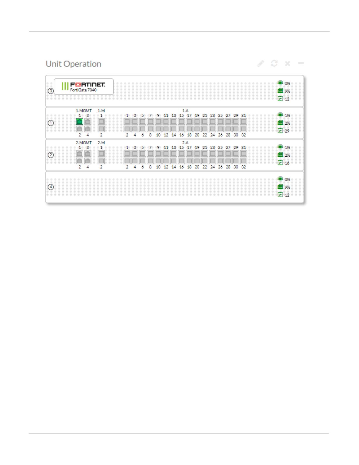
The following example Unit Operation dashboard widget shows a FortiGate-7040E with FIM-7901E modules in
slots 1 and 2 and FPM modules in slots 3 and 4.
31 FortiGate-7000
Fortinet Technologies Inc.
Page 32
Getting started with FortiGate-7000 Managing individual modules
Example FortiGate-7040 unit operation widget view
Managing individual modules
When you log into the GUI or CLI using the mgmt interface IP address you are actually connected to the primary
(or master) interface module in slot 1 (the address of slot 1 is FIM01). To verify which module you have logged
into, the GUI header banner or CLI prompt shows the hostname of the module you are logged into plus the slot
address in the format <hostname> (<slot address>).
In some cases you may want to connect to individual modules. For example, you may want to view the traffic
being processed by a specific processor module. You can connect to the GUI or CLIof individual modules in the
chassis using the system management IP address with a special port number.
For example, if the system management IP address is 192.168.1.99 you can connect to the GUIof the interface
module in slot 1 using the system management IP address (for example, by browsing to https://192.168.1.99).
You can also use the system management IP address followed by the special port number, for example
https://192.168.1.99:44301.
The special port number (in this case 44301)is a combination of the service port (for HTTPS the service port is
443) and the chassis slot number (in this example, 01). The following table lists the special ports to use to
connect to each chassis slot using common admin protocols:
FortiGate-7000
Fortinet Technologies Inc.
32
Page 33

Connecting to module CLIs using the management module Getting started with FortiGate-7000
FortiGate-7000 special administration port numbers
Slot Number Slot Address
5 Processor module FPM05 8005 44305 2305 2205 16105
3 Processor module FPM03 8003 44303 2303 2203 16103
1 Primary Interface module FIM01 8001 44301 2301 2201 16101
2 Interface module FIM02 8002 44302 2302 2202 16102
4 Processor module FPM04 8004 44304 2304 2204 16104
6 Processor module FPM06 8006 44306 2306 2206 16106
For example:
l To connect to the GUI of the interface module in slot 3 using HTTPS you would browse to
https://192.168.1.99:44303.
l To send an SNMP query to the processor module in slot 6 use the port number 16106.
The FortiGate-7000 configuration is the same no matter which modem you log into. Logging into different
modules allows you to use FortiView or Monitor GUI pages to view the activity on that module. Even though you
can log into different modules, you should only make configuration changes from the primary interface module;
which is the FIMmodule in slot 1.
HTTP
(80)
HTTPS (443)
Telnet
(23)
SSH (22) SNMP (161)
Managing individual modules from the CLI
From the CLI you can use the following command to switch between chassis slots and perform different
operations on the modules in each slot:
execute load-balance slot {manage | power-off | power-on | reboot} <slot-number>
Use manage to connect to the CLI of a different module, use power-off, power-on, and reboot to turn off
or turn on the power or reboot the module in <slot-number>.
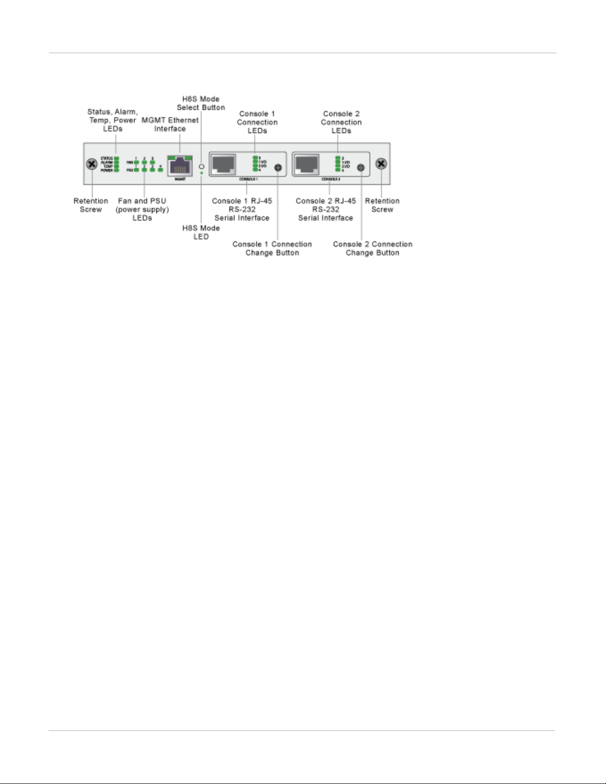
Connecting to module CLIs using the management module
All FortiGate-7000 chassis includes a front panel management module (also called a shelf manager) on the
chassis front panel. See the system guide for your chassis for details about the management module.
33 FortiGate-7000
Fortinet Technologies Inc.
Page 34
Getting started with FortiGate-7000 Connecting to module CLIs using the management module
ForiGate-7040E management module front panel
The management module includes two console ports named Console 1 and Console 2 that can be used to
connect to the CLI of the FIM and FPM modules in the chassis. As described in the system guide, the console
ports are also used to connect to SMC CLIs of the management module and the FIM and FPMmodules
By default when the chassis first starts up Console 1 is connected to the FortiOS CLI of the FIM module in slot 1
and Console 2 is disconnected. The default settings for connecting to each console port are:
Baud Rate (bps) 9600, Data bits 8, Parity None, Stop bits 1, and Flow Control None.
You can use the console connection change buttons to select the CLI that each console port is connected to.
Press the button to cycle through the FIM and FPM module FortiOS CLIs and disconnect this console. The
console's LEDs indicate what it is connected to. If no LED is lit the console is either connected to the
management module SMC SDI console or disconnected. Both console ports cannot be connected to the same
CLI at the same time. If a console button press would cause a conflict that module is skipped. If one of the
console ports is disconnected then the other console port can connect to any CLI.
If you connect a PC to one of the management module console ports with a serial cable and open a terminal
session you begin by pressing Ctrl-T to enable console switching mode. Press Ctrl-T multiple times to cycle
through the FIM and FPM module FortiOS CLIs (the new destination is displayed in the terminal window). If you
press Ctrl-T after connecting to the FPM module in the highest slot number, the console is disconnected. Press
Ctrl-T again to start over again at slot 1.
Once the console port is connected to the CLI that you want to use, press Enter to enable the CLI and login. The
default administrator account for accessing the FortiOS CLIs is admin with no password.
When your session is complete you can press Ctrl-T until the prompt shows you have disconnected from the
console.
Connecting to the FortiOS CLI of the FIM module in slot 1
Use the following steps to connect to the FortiOS CLI of the FIM module in slot 1:
1.
Connect the console cable supplied with your chassis to Console 1 and to your PC or other device RS-232 console
port.
2.
Start a terminal emulation program on the management computer. Use these settings:
Baud Rate (bps) 9600, Data bits 8, Parity None, Stop bits 1, and Flow Control None.
FortiGate-7000
Fortinet Technologies Inc.
34
Page 35

Default VDOM configuration Getting started with FortiGate-7000
3.
Press Ctrl-T to enter console switch mode.
4.
Repeat pressing Ctrl-T until you have connected to slot 1. Example prompt:
<Switching to Console: FIM01 (9600)>
5.
Login with an administrator name and password.
The default is admin with no password. For security reasons, it is strongly recommended that you change the
password.
6.
When your session is complete, enter the exit command to log out.
Default VDOM configuration
By default when the FortiGate-7000 first starts up it is operating in multiple VDOM mode. The system has a
management VDOM (named dmgmt-vdom) and the root VDOM. All management interfaces are in dmgmt-vdom
and all other interfaces are in the root VDOM. You can add more VDOMs and add interfaces to them or just use
the root VDOM.
Default management VDOM
By default the FortiGate-7000 configuration includes a management VDOMnamed dmgmt-vdom. For the
FortiGate-7000 system to operate normally you should not change the configuration of this VDOM and this
VDOM should always be the management VDOM. You should also not add or remove interfaces from this
VDOM.
You have full control over the configurations of other FortiGate-7000 VDOMs.
Firmware upgrades
All of the modules in your FortiGate-7000 run the same firmware image. You upgrade the firmware from the
primary interface module GUIor CLI just as you would any FortiGate product. During the upgrade process the
firmware of all of the modules in the chassis upgrades in one step. Firmware upgrades should be done during a
quiet time because traffic will briefly be interrupted during the upgrade process.
If you are operating two FortiGate-7000 chassis in HA mode with uninterruptable-upgrade and
session-pickup enabled, firmware upgrades should only cause a minimal traffic interruption. Use the
following command to enable these settings. These settings are synchronized to all modules in the cluster.
config system ha
set uninterruptable-upgrade enable
set session-pickup enable
end
Restarting the FortiGate-7000
To restart all of the modules in a FortiGate-7000 chassis, connect to the primary FIMmodule CLI and enter the
command execute reboot. When you enter this command all of the modules in the chassis reboot.
35 FortiGate-7000
Fortinet Technologies Inc.
Page 36

Getting started with FortiGate-7000 Load balancing
You can restart individual modules by logging into that module's CLI and entering the execute reboot
command.
Load balancing
FortiGate-7000E session-aware load balancing (SLBC) distributes TCP, UDP, and SCTP traffic from the interface
modules to the processor modules. Traffic is load balanced based on the algorithm set by the following
command:
config load-balance setting
set dp-load-distribution-method {round-robin | src-ip | dst-ip | src-dst-ip | src-ip-
sport | dst-ip-dport | src-dst-ip-sport-dport}
end
Where:
round-robin Directs new requests to the next slot regardless of response time or number of connections.
src-ip traffic load is distributed across all slots according to source IP address.
dst-ip traffic load is statically distributed across all slots according to destination IP address.
src-dst-ip traffic load is distributed across all slots according to the source and destination IP addresses.
src-ip-sport traffic load is distributed across all slots according to the source IP address and source port.
dst-ip-dport traffic load is distributed across all slots according to the destination IP address and destination
port.
src-dst-ipsport-dport traffic load is distributed across all slots according to the source and destination IP
address, source port, and destination port. This is the default load balance distribution method and represents
true session-aware load balancing.
Traffic that cannot be load balanced
Some traffic types cannot be load balanced. Traffic that cannot be load balanced is all processed by the primary
FPM module, which is usually the FPM module in slot 3. Internal to the system this FPM module is designated as
the ELBC master. If the FPM module in slot 3 fails or is rebooted, the next FPMmodule will become the primary
FPM module.
You can configure the FortiGate-7000 to send any type of traffic to the primary FPM or to other specific FPM
modules using the config loadbalance flow-rule command. By default, traffic that is only sent to the
primary FPM module includes, IPsec, IKE, GRE, session helper, Kerberos, BGP, RIP, IPv4 and IPv6 DHCP,
PPTP, BFD, IPv4 multicast and IPv6 multicast. You can view the default configuration of the config
loadbalance flow-rule command to see how this is all configured. For example, the following
configuration sends all IKE traffic to the primary FPM:
config load-balance flow-rule
edit 1
set status enable
set vlan 0
set ether-type ip
set protocol udp
set src-l4port 500-500
set dst-l4port 500-500
set action forward
FortiGate-7000
Fortinet Technologies Inc.
36
Page 37

Recommended configuration for traffic that cannot be load balanced Getting started with FortiGate-7000
set forward-slot master
set priority 5
set comment "ike"
next
edit 2
set status disable
set vlan 0
set ether-type ip
set protocol udp
set src-l4port 4500-4500
set dst-l4port 0-0
set action forward
set forward-slot master
set priority 5
set comment "ike-natt src"
next
edit 3
set status disable
set vlan 0
set ether-type ip
set protocol udp
set src-l4port 0-0
set dst-l4port 4500-4500
set action forward
set forward-slot master
set priority 5
set comment "ike-natt dst"
next
Recommended configuration for traffic that cannot be load balanced
The following flow rules are recommended to handle common forms of traffic that cannot be load balanced.
These flow rules send GPRS (port 2123), SSL VPN, IPv4 and IPv6 IPsec VPN, ICMP and ICMPv6 traffic to the
primary (or master) FPM.
The CLI syntax below just shows the configuration changes. All other options are set to their defaults. For
example, the flow rule option that controls the FPM slot that sessions are sent to is forward-slot and in all
cases below forward-slot is set to its default setting of master. This setting sends matching sessions to the
primary (or master) FPM.
config load-balance flow-rule
edit 20
set status enable
set ether-type ipv4
set protocol udp
set dst-l4port 2123-2123
next
edit 21
set status enable
set ether-type ip
set protocol tcp
set dst-l4port 10443-10443
set comment "ssl vpn to the primary FPM"
next
edit 22
37 FortiGate-7000
Fortinet Technologies Inc.
Page 38

Getting started with FortiGate-7000 Recommended configuration for traffic that cannot be load balanced
set status enable
set ether-type ipv4
set protocol udp
set src-l4port 500-500
set dst-l4port 500-500
set comment "ipv4 ike"
next
edit 23
set status enable
set ether-type ipv4
set protocol udp
set src-l4port 4500-4500
set comment "ipv4 ike-natt src"
next
edit 24
set status enable
set ether-type ipv4
set protocol udp
set dst-l4port 4500-4500
set comment "ipv4 ike-natt dst"
next
edit 25
set status enable
set ether-type ipv4
set protocol esp
set comment "ipv4 esp"
next
edit 26
set status enable
set ether-type ipv6
set protocol udp
set src-l4port 500-500
set dst-l4port 500-500
set comment "ipv6 ike"
next
edit 27
set status enable
set ether-type ipv6
set protocol udp
set src-l4port 4500-4500
set comment "ipv6 ike-natt src"
next
edit 28
set status enable
set ether-type ipv6
set protocol udp
set dst-l4port 4500-4500
set comment "ipv6 ike-natt dst"
next
edit 29
set status enable
set ether-type ipv6
set protocol esp
set comment "ipv6 esp"
next
edit 30
set ether-type ipv4
FortiGate-7000
Fortinet Technologies Inc.
38
Page 39

Configuration synchronization Getting started with FortiGate-7000
set protocol icmp
set comment "icmp"
next
edit 31
set status enable
set ether-type ipv6
set protocol icmpv6
set comment "icmpv6"
next
edit 32
set ether-type ipv6
set protocol 41
end
Configuration synchronization
The FortiGate-7000 synchronizes the configuration to all modules in the chassis. To support this feature, the
interface module in slot 1 becomes the config-sync master and this module makes sure the configurations of all
modules are synchronized. Every time you make a configuration change you must be logged into the chassis
using the management address, which logs you into the config-sync master. All configuration changes made to
the config-sync master are synchronized to all of the modules in the chassis.
If the FIM module in slot 1 fails or reboots, the FIM module in slot 2 becomes the config-sync master.
Failover in a standalone FortiGate-7000
A FortiGate-7000 will continue to operate even if one of the FIM or FPM modules fails or is removed. If an FPM
module fails, sessions being processed by that module fail. All sessions are then load balanced to the remaining
FPMmodules. Sessions that were being processed by the failed module are restarted and load balanced to the
remaining FPM modules.
If an FIM module fails, the other FIM module will continue to operate and will become the config-sync master.
However, traffic received by the failed FIM module will be lost.
You can use LACP or redundant interfaces to connect interfaces of both FIMs to the same network. In this way, if
one of the FIMs fails the traffic will continue to be received by the other FIM module.
Replacing a failed FPMor FIMmodule
This section describes how to remove a failed FPM or FIM module and replace it with a new one. The procedure
is slightly different depending on if you are operating in HA mode with two chassis or just operating a standalone
chassis.
Replacing a failed module in a standalone FortiGate-7000 chassis
1.
Power down the failed module by pressing the front panel power button.
2.
Remove the module from the chassis.
3.
Insert the replacement module. It should power up when inserted into the chassis if the chassis has power.
39 FortiGate-7000
Fortinet Technologies Inc.
Page 40

Getting started with FortiGate-7000 Replacing a failed FPMor FIMmodule
4.
The module's configuration is synchronized and its firmware is upgraded to match the firmware version on the
primary module. The new module reboots.
5.
If the module will be running FortiOS Carrier, apply the FortiOS Carrier license to the module. The module
reboots.
6.
Confirm that the new module is running the correct firmware version either from the GUI or by using the config
system status command.
Manually update the module to the correct version if required. You can do this by logging into the module and
performing a firmware upgrade.
7.
Verify that the configuration has been synchronized.
The following command output shows the sync status of the FIM modules in a FortiGate-7000 chassis. The field
in_sync=1 indicates that the configurations of the modules are synchronized.
diagnose sys confsync
status | grep in_sy
FIM04E3E16000080, Slave, uptime=177426.45, priority=2,
slot_id=1:2, idx=0, flag=0x0, in_sync=1
FIM10E3E16000063, Master, uptime=177415.38, priority=1,
slot_id=1:1, idx=1, flag=0x0, in_sync=1
If in_sync is not equal to 1 or if a module is missing in the command output you can try restarting the
modules in the chassis by entering execute reboot from any module CLI. If this does not solve the problem,
contact Fortinet support.
Replacing a failed module in a FortiGate-7000 chassis inan HAcluster
1.
Power down the failed module by pressing the front panel power button.
2.
Remove the module from the chassis.
3.
Insert the replacement module. It should power up when inserted into the chassis if the chassis has power.
4.
The module's configuration is synchronized and its firmware is upgraded to match the configuration and firmware
version on the primary module. The new module reboots.
5.
If the module will be running FortiOS Carrier, apply the FortiOS Carrier license to the module. The module
reboots.
6.
Confirm that the module is running the correct firmware version.
Manually update the module to the correct version if required. You can do this by logging into the module and
performing a firmware upgrade.
7.
Configure the new module for HA operation. For example:
config system ha
set mode a-p
set chassis-id 1
set hbdev m1 m2
set hbdev-vlan-id 999
set hbdev-second-vlan-id 990
end
8.
Optionally configure the hostname:
config system global
set hostname <name>
end
The HA configuration and the hostname must be set manually because HA settings and the hostname is not
synchronized.
9.
Verify that the configuration has been synchronized.
The following command output shows the sync status of the FIM modules in a FortiGate-7000 chassis. The field
FortiGate-7000
Fortinet Technologies Inc.
40
Page 41

Installing firmware on an FIM or FPM module from the BIOS using a TFTP server Getting started with FortiGate-7000
in_sync=1 indicates that the configurations of the modules are synchronized.
diagnose sys confsync
status | grep in_sy
FIM04E3E16000080, Slave, uptime=177426.45, priority=2,
slot_id=1:2, idx=0, flag=0x0, in_sync=1
FIM10E3E16000063, Master, uptime=177415.38, priority=1,
slot_id=1:1, idx=1, flag=0x0, in_sync=1
If in_sync is not equal to 1 or if a module is missing in the command output you can try restarting the
modules in the chassis by entering execute reboot from any module CLI. If this does not solve the problem,
contact Fortinet support.
Installing firmware on an FIM or FPM module from the BIOS using a TFTP server
Use the procedures in this section to install firmware on a FIM or FPM module from a TFTP server after
interrupting the boot up sequence from the BIOS.
You might want to use this procedure if you need to reset the configuration of a module to factory defaults by
installing firmware from a reboot. You can also use this procedure if you have formatted one or more FIMor
FPMmodules from the BIOS by interrupting the boot process.
This procedure involves creating a connection between a TFTP server and one of the MGMT interfaces of one of
the FIMmodules, using a chassis console port to connect to the CLI of the module that you are upgrading the
firmware for, rebooting this module, interrupting the boot from the console session, and installing the firmware.
This section includes two procedures, one for upgrading FIM modules and one for upgrading FPM modules. The
two procedures are very similar but a few details, most notably the local VLAN ID setting are different. If you need
to update both FIM and FPM modules, you should update the FIM modules first as the FPM modules can only
communicate with the TFTP server through FIMmodule interfaces.
Uploading firmware from a TFTP server to an FIMmodule
Use the following steps to upload firmware from a TFTP server to an FIM module. This procedure requires
Ethernet connectivity between the TFTP server and one of the FIM module's MGMT interfaces.
During this procedure, the FIM module will not be able to process traffic so, if possible, perform this procedure
when the network is not processing any traffic.
If you are operating an HA configuration, you should remove the chassis from the HA configuration before
performing this procedure.
1.
Set up a TFTP server and copy the firmware file to be installed into the TFTP server default folder.
2.
Set up your network to allow traffic between the TFTP server and one of the MGMT interfaces of the FIM module
to be updated.
If the MGMT interface you are using is one of the MGMT interfaces connected as a LAG to a switch you must
shutdown or disconnect all of the other connections in the LAG from the switch. This includes the MGMT
interfaces in the other FIM module.
3.
Connect the console cable supplied with your chassis to the Console 1 port on your chassis front panel and to your
management computer's RS-232 console port.
4.
Start a terminal emulation program on the management computer. Use these settings:
Baud Rate (bps) 9600, Data bits 8, Parity None, Stop bits 1, and Flow Control None.
41 FortiGate-7000
Fortinet Technologies Inc.
Page 42

Getting started with FortiGate-7000 Installing firmware on an FIM or FPM module from the BIOS using a TFTP server
5.
Press Ctrl-T to enter console switch mode.
6.
Repeat pressing Ctrl-T until you have connected to the module to be updated. Example prompt:
<Switching to Console: FIM02 (9600)>
7.
Optionally log into the FIM module's CLI.
8.
Reboot the FIM module to be updated.
You can do this using the execute reboot command from the CLI or by pressing the power switch on the
module front panel.
9.
When the FIM module starts up, follow the boot process in the terminal session and press any key when prompted
to interrupt the boot process.
10.
Press C to set up the TFTP configuration.
11.
Use the BIOS menu to set the following. Only change settings if required.
[P]: Set image download port: MGMT1 (change if required)
[D]: Set DHCP mode: Disabled
[I]: Set local IP address: A temporary IP address to be used to connect to the TFTP server. This
address must not be the same as the chassis management IP address and cannot conflict with other
addresses on your network
[S]: Set local Subnet Mask: Set as required for your network.
[G]: Set local gateway: Set as required for your network.
[V]: Local VLAN ID: Use -1 to clear the Local VLAN ID.
[T]: Set remote TFTP server IP address: The IP address of the TFTP server.
[F]: Set firmware image file name: The name of the firmware file to be installed.
12.
Press Q to quit this menu.
13.
Press R to review the configuration.
If you need to make any corrections, press C and make the changes as required. When the configuration is correct
proceed to the next step.
14.
Press T to start the TFTP transfer.
The firmware image is uploaded from the TFTP server and installed on the FIM module which then reboots. When
it starts up the module's configuration is reset to factory defaults. The module's configuration is synchronized to
match the configuration of the primary module. The new module reboots again and can start processing traffic.
15.
Verify that the configuration has been synchronized.
The following command output shows the sync status of the FIM modules in a FortiGate-7000 chassis. The field
in_sync=1 indicates that the configurations of the modules are synchronized.
diagnose sys confsync
status | grep in_sy
FIM04E3E16000080, Slave, uptime=177426.45, priority=2,
slot_id=1:2, idx=0, flag=0x0, in_sync=1
FIM10E3E16000063, Master, uptime=177415.38, priority=1,
slot_id=1:1, idx=1, flag=0x0, in_sync=1
If in_sync is not equal to 1 or if a module is missing in the command output you can try restarting the
modules in the chassis by entering execute reboot from any module CLI. If this does not solve the problem,
contact Fortinet support.
FortiGate-7000
Fortinet Technologies Inc.
42
Page 43

Installing firmware on an FIM or FPM module from the BIOS using a TFTP server Getting started with FortiGate-7000
Uploading firmware from a TFTP server to an FPMmodule
Use the following steps to upload firmware from a TFTP server to an FPM module. This procedure requires
Ethernet connectivity between the TFTP server and one of the MGMT interfaces of one of the FIM modules in
the same chassis as the FPM module.
During this procedure, the FPM module will not be able to process traffic so, if possible, perform this procedure
when the network is not processing any traffic. However, the other FPM modules and the FIM modules in the
chassis should continue to operate normally and the chassis can continue processing traffic.
If you are operating an HA configuration, you should remove the chassis from the HA configuration before
performing this procedure.
1.
Set up a TFTP server and copy the firmware file to be installed into the TFTP server default folder.
2.
Set up your network to allow traffic between the TFTP server and a MGMT interface of one of the FIM modules in
the chassis that also includes the FPMmodule.
You can use any MGMT interface of either of the FIM modules. If the MGMT interface you are using is one of the
MGMT interfaces connected as a LAG to a switch you must shutdown or disconnect all of the other connections in
the LAG from the switch. This includes the MGMT interfaces in the other FIM module.
3.
Connect the console cable supplied with your chassis to the Console 1 port on your chassis front panel and to your
management computer's RS-232 console port.
4.
Start a terminal emulation program on the management computer. Use these settings:
Baud Rate (bps) 9600, Data bits 8, Parity None, Stop bits 1, and Flow Control None.
5.
Press Ctrl-T to enter console switch mode.
6.
Repeat pressing Ctrl-T until you have connected to the module to be updated. Example prompt:
<Switching to Console: FPM03 (9600)>
7.
Optionally log into the FPM module's CLI.
8.
Reboot the FPM module to be updated.
You can do this using the execute reboot command from the CLI or by pressing the power switch on the
module front panel.
9.
When the FPM module starts up, follow the boot process in the terminal session and press any key when
prompted to interrupt the boot process.
10.
Press C to set up the TFTP configuration.
11.
Use the BIOS menu to set the following. Only change settings if required.
[P]: Set image download port: The name of the FIM module that can connect to the TFTP server
(FIM01 is the FIM module in slot 1 and FIM02 is the FIMmodule in slot 2).
[D]: Set DHCP mode: Disabled.
[I]: Set local IP address: A temporary IP address to be used to connect to the TFTP server. This
address must not be the same as the chassis management IP address and cannot conflict with other
addresses on your network.
[S]: Set local Subnet Mask: Set as required for your network.
[G]: Set local gateway: Set as required for your network.
[V]: Local VLAN ID: The VLAN ID of the FIM interface that can connect to the TFTP server:
FIM01 local VLAN IDs
43 FortiGate-7000
Fortinet Technologies Inc.
Page 44

Getting started with FortiGate-7000 Installing firmware on an FIM or FPM module from the BIOS using a TFTP server
Interface MGMT1 MGMT2 MGMT3 MGMT4
Local VLAN ID 11 12 13 14
FIM02 local VLAN IDs
Interface MGMT1 MGMT2 MGMT3 MGMT4
Local VLAN ID 21 22 23 24
[T]: Set remote TFTP server IP address: The IP address of the TFTP server.
[F]: Set firmware image file name: The name of the firmware file to be installed.
12.
Press Q to quit this menu.
13.
Press R to review the configuration.
If you need to make any corrections, press C and make the changes as required. When the configuration is correct
proceed to the next step.
14.
Press T to start the TFTP transfer.
The firmware image is uploaded from the TFTP server and installed on the FPM module which then reboots.
When it starts up the module's configuration is reset to factory defaults. The module's configuration is
synchronized to match the configuration of the primary module. The new module reboots again and can start
processing traffic.
15.
Verify that the configuration has been synchronized.
The following command output shows the sync status of the FIM modules in a FortiGate-7000 chassis. The field
in_sync=1 indicates that the configurations of the modules are synchronized.
diagnose sys confsync
status | grep in_sy
FIM04E3E16000080, Slave, uptime=177426.45, priority=2,
slot_id=1:2, idx=0, flag=0x0, in_sync=1
FIM10E3E16000063, Master, uptime=177415.38, priority=1,
slot_id=1:1, idx=1, flag=0x0, in_sync=1
If in_sync is not equal to 1 or if a module is missing in the command output you can try restarting the
modules in the chassis by entering execute reboot from any module CLI. If this does not solve the problem,
contact Fortinet support.
FortiGate-7000
Fortinet Technologies Inc.
44
Page 45

Failover in a standalone FortiGate-7000 Operating a FortiGate-7000
Operating a FortiGate-7000
This chapter describes some FortiGate-7000 general operating procedure.
Failover in a standalone FortiGate-7000
A FortiGate-7000 will continue to operate even if one of the FIM or FPM modules fails or is removed. If an FPM
module fails, sessions being processed by that module fail. All sessions are then load balanced to the remaining
FPMmodules. Sessions that were being processed by the failed module are restarted and load balanced to the
remaining FPM modules.
If an FIM module fails, the other FIM module will continue to operate and will become the config-sync master.
However, traffic received by the failed FIM module will be lost.
You can use LACP or redundant interfaces to connect interfaces of both FIMs to the same network. In this way, if
one of the FIMs fails the traffic will continue to be received by the other FIM module.
Replacing a failed FPMor FIMmodule
This section describes how to remove a failed FPM or FIM module and replace it with a new one. The procedure
is slightly different depending on if you are operating in HA mode with two chassis or just operating a standalone
chassis.
Replacing a failed module in a standalone FortiGate-7000 chassis
1.
Power down the failed module by pressing the front panel power button.
2.
Remove the module from the chassis.
3.
Insert the replacement module. It should power up when inserted into the chassis if the chassis has power.
4.
The module's configuration is synchronized and its firmware is upgraded to match the firmware version on the
primary module. The new module reboots.
5.
Confirm that the new module is running the correct firmware version either from the GUI or by using the config
system status command.
Manually update the module to the correct version if required. You can do this by logging into the module and
performing a firmware upgrade.
6.
Verify that the configuration has been synchronized.
The following command output shows the sync status of the FIM modules in a FortiGate-7000 chassis. The field
in_sync=1 indicates that the configurations of the modules are synchronized.
diagnose sys confsync
status | grep in_sy
FIM04E3E16000080, Slave, uptime=177426.45, priority=2,
slot_id=1:2, idx=0, flag=0x0, in_sync=1
FIM10E3E16000063, Master, uptime=177415.38, priority=1,
slot_id=1:1, idx=1, flag=0x0, in_sync=1
45 FortiGate-7000
Fortinet Technologies Inc.
Page 46

Operating a FortiGate-7000 Installing firmware on an FIM or FPM module from the BIOS using a TFTP server
If in_sync is not equal to 1 or if a module is missing in the command output you can try restarting the
modules in the chassis by entering execute reboot from any module CLI. If this does not solve the problem,
contact Fortinet support.
Replacing a failed module in a FortiGate-7000 chassis inan HAcluster
1.
Power down the failed module by pressing the front panel power button.
2.
Remove the module from the chassis.
3.
Insert the replacement module. It should power up when inserted into the chassis if the chassis has power.
4.
The module's configuration is synchronized and its firmware is upgraded to match the configuration and firmware
version on the primary module. The new module reboots.
5.
Confirm that the module is running the correct firmware version.
Manually update the module to the correct version if required. You can do this by logging into the module and
performing a firmware upgrade.
6.
Configure the new module for HA operation. For example:
config system ha
set mode a-p
set chassis-id 1
set hbdev m1 m2
set hbdev-vlan-id 999
set hbdev-second-vlan-id 990
end
7.
Optionally configure the hostname:
config system global
set hostname <name>
end
The HA configuration and the hostname must be set manually because HA settings and the hostname is not
synchronized.
8.
Verify that the configuration has been synchronized.
The following command output shows the sync status of the FIM modules in a FortiGate-7000 chassis. The field
in_sync=1 indicates that the configurations of the modules are synchronized.
diagnose sys confsync
status | grep in_sy
FIM04E3E16000080, Slave, uptime=177426.45, priority=2,
slot_id=1:2, idx=0, flag=0x0, in_sync=1
FIM10E3E16000063, Master, uptime=177415.38, priority=1,
slot_id=1:1, idx=1, flag=0x0, in_sync=1
If in_sync is not equal to 1 or if a module is missing in the command output you can try restarting the
modules in the chassis by entering execute reboot from any module CLI. If this does not solve the problem,
contact Fortinet support.
Installing firmware on an FIM or FPM module from the BIOS using a TFTP server
Use the procedures in this section to install firmware on a FIM or FPM module from a TFTP server after
interrupting the boot up sequence from the BIOS.
FortiGate-7000
Fortinet Technologies Inc.
46
Page 47

Installing firmware on an FIM or FPM module from the BIOS using a TFTP server Operating a FortiGate-7000
You might want to use this procedure if you need to reset the configuration of a module to factory defaults by
installing firmware from a reboot. You can also use this procedure if you have formatted one or more FIMor
FPMmodules from the BIOS by interrupting the boot process.
This procedure involves creating a connection between a TFTP server and one of the MGMT interfaces of one of
the FIMmodules, using a chassis console port to connect to the CLI of the module that you are upgrading the
firmware for, rebooting this module, interrupting the boot from the console session, and installing the firmware.
This section includes two procedures, one for upgrading FIM modules and one for upgrading FPM modules. The
two procedures are very similar but a few details, most notably the local VLAN ID setting are different. If you need
to update both FIM and FPM modules, you should update the FIM modules first as the FPM modules can only
communicate with the TFTP server through FIMmodule interfaces.
Uploading firmware from a TFTP server to an FIMmodule
Use the following steps to upload firmware from a TFTP server to an FIM module. This procedure requires
Ethernet connectivity between the TFTP server and one of the FIM module's MGMT interfaces.
During this procedure, the FIM module will not be able to process traffic so, if possible, perform this procedure
when the network is not processing any traffic.
If you are operating an HA configuration, you should remove the chassis from the HA configuration before
performing this procedure.
1.
Set up a TFTP server and copy the firmware file to be installed into the TFTP server default folder.
2.
Set up your network to allow traffic between the TFTP server and one of the MGMT interfaces of the FIM module
to be updated.
If the MGMT interface you are using is one of the MGMT interfaces connected as a LAG to a switch you must
shutdown or disconnect all of the other connections in the LAG from the switch. This includes the MGMT
interfaces in the other FIM module.
3.
Connect the console cable supplied with your chassis to the Console 1 port on your chassis front panel and to your
management computer's RS-232 console port.
4.
Start a terminal emulation program on the management computer. Use these settings:
Baud Rate (bps) 9600, Data bits 8, Parity None, Stop bits 1, and Flow Control None.
5.
Press Ctrl-T to enter console switch mode.
6.
Repeat pressing Ctrl-T until you have connected to the module to be updated. Example prompt:
<Switching to Console: FIM02 (9600)>
7.
Optionally log into the FIM module's CLI.
8.
Reboot the FIM module to be updated.
You can do this using the execute reboot command from the CLI or by pressing the power switch on the
module front panel.
9.
When the FIM module starts up, follow the boot process in the terminal session and press any key when prompted
to interrupt the boot process.
10.
Press C to set up the TFTP configuration.
11.
Use the BIOS menu to set the following. Only change settings if required.
[P]: Set image download port: MGMT1 (change if required)
[D]: Set DHCP mode: Disabled
47 FortiGate-7000
Fortinet Technologies Inc.
Page 48

Operating a FortiGate-7000 Installing firmware on an FIM or FPM module from the BIOS using a TFTP server
[I]: Set local IP address: A temporary IP address to be used to connect to the TFTP server. This
address must not be the same as the chassis management IP address and cannot conflict with other
addresses on your network
[S]: Set local Subnet Mask: Set as required for your network.
[G]: Set local gateway: Set as required for your network.
[V]: Local VLAN ID: Use -1 to clear the Local VLAN ID.
[T]: Set remote TFTP server IP address: The IP address of the TFTP server.
[F]: Set firmware image file name: The name of the firmware file to be installed.
12.
Press Q to quit this menu.
13.
Press R to review the configuration.
If you need to make any corrections, press C and make the changes as required. When the configuration is correct
proceed to the next step.
14.
Press T to start the TFTP transfer.
The firmware image is uploaded from the TFTP server and installed on the FIM module which then reboots. When
it starts up the module's configuration is reset to factory defaults. The module's configuration is synchronized to
match the configuration of the primary module. The new module reboots again and can start processing traffic.
15.
Verify that the configuration has been synchronized.
The following command output shows the sync status of the FIM modules in a FortiGate-7000 chassis. The field
in_sync=1 indicates that the configurations of the modules are synchronized.
diagnose sys confsync
status | grep in_sy
FIM04E3E16000080, Slave, uptime=177426.45, priority=2,
slot_id=1:2, idx=0, flag=0x0, in_sync=1
FIM10E3E16000063, Master, uptime=177415.38, priority=1,
slot_id=1:1, idx=1, flag=0x0, in_sync=1
If in_sync is not equal to 1 or if a module is missing in the command output you can try restarting the
modules in the chassis by entering execute reboot from any module CLI. If this does not solve the problem,
contact Fortinet support.
Uploading firmware from a TFTP server to an FPMmodule
Use the following steps to upload firmware from a TFTP server to an FPM module. This procedure requires
Ethernet connectivity between the TFTP server and one of the MGMT interfaces of one of the FIM modules in
the same chassis as the FPM module.
During this procedure, the FPM module will not be able to process traffic so, if possible, perform this procedure
when the network is not processing any traffic. However, the other FPM modules and the FIM modules in the
chassis should continue to operate normally and the chassis can continue processing traffic.
If you are operating an HA configuration, you should remove the chassis from the HA configuration before
performing this procedure.
1.
Set up a TFTP server and copy the firmware file to be installed into the TFTP server default folder.
2.
Set up your network to allow traffic between the TFTP server and a MGMT interface of one of the FIM modules in
the chassis that also includes the FPMmodule.
You can use any MGMT interface of either of the FIM modules. If the MGMT interface you are using is one of the
MGMT interfaces connected as a LAG to a switch you must shutdown or disconnect all of the other connections in
the LAG from the switch. This includes the MGMT interfaces in the other FIM module.
FortiGate-7000
Fortinet Technologies Inc.
48
Page 49

Installing firmware on an FIM or FPM module from the BIOS using a TFTP server Operating a FortiGate-7000
3.
Connect the console cable supplied with your chassis to the Console 1 port on your chassis front panel and to your
management computer's RS-232 console port.
4.
Start a terminal emulation program on the management computer. Use these settings:
Baud Rate (bps) 9600, Data bits 8, Parity None, Stop bits 1, and Flow Control None.
5.
Press Ctrl-T to enter console switch mode.
6.
Repeat pressing Ctrl-T until you have connected to the module to be updated. Example prompt:
<Switching to Console: FPM03 (9600)>
7.
Optionally log into the FPM module's CLI.
8.
Reboot the FPM module to be updated.
You can do this using the execute reboot command from the CLI or by pressing the power switch on the
module front panel.
9.
When the FPM module starts up, follow the boot process in the terminal session and press any key when
prompted to interrupt the boot process.
10.
Press C to set up the TFTP configuration.
11.
Use the BIOS menu to set the following. Only change settings if required.
[P]: Set image download port: The name of the FIM module that can connect to the TFTP server
(FIM01 is the FIM module in slot 1 and FIM02 is the FIMmodule in slot 2).
[D]: Set DHCP mode: Disabled.
[I]: Set local IP address: A temporary IP address to be used to connect to the TFTP server. This
address must not be the same as the chassis management IP address and cannot conflict with other
addresses on your network.
[S]: Set local Subnet Mask: Set as required for your network.
[G]: Set local gateway: Set as required for your network.
[V]: Local VLAN ID: The VLAN ID of the FIM interface that can connect to the TFTP server:
FIM01 local VLAN IDs
Interface MGMT1 MGMT2 MGMT3 MGMT4
Local VLAN ID 11 12 13 14
FIM02 local VLAN IDs
Interface MGMT1 MGMT2 MGMT3 MGMT4
Local VLAN ID 21 22 23 24
[T]: Set remote TFTP server IP address: The IP address of the TFTP server.
[F]: Set firmware image file name: The name of the firmware file to be installed.
12.
Press Q to quit this menu.
13.
Press R to review the configuration.
If you need to make any corrections, press C and make the changes as required. When the configuration is correct
proceed to the next step.
14.
Press T to start the TFTP transfer.
The firmware image is uploaded from the TFTP server and installed on the FPM module which then reboots.
49 FortiGate-7000
Fortinet Technologies Inc.
Page 50

Operating a FortiGate-7000 Installing firmware on an FIM or FPM module from the BIOS using a TFTP server
When it starts up the module's configuration is reset to factory defaults. The module's configuration is
synchronized to match the configuration of the primary module. The new module reboots again and can start
processing traffic.
15.
Verify that the configuration has been synchronized.
The following command output shows the sync status of the FIM modules in a FortiGate-7000 chassis. The field
in_sync=1 indicates that the configurations of the modules are synchronized.
diagnose sys confsync
status | grep in_sy
FIM04E3E16000080, Slave, uptime=177426.45, priority=2,
slot_id=1:2, idx=0, flag=0x0, in_sync=1
FIM10E3E16000063, Master, uptime=177415.38, priority=1,
slot_id=1:1, idx=1, flag=0x0, in_sync=1
If in_sync is not equal to 1 or if a module is missing in the command output you can try restarting the
modules in the chassis by entering execute reboot from any module CLI. If this does not solve the problem,
contact Fortinet support.
FortiGate-7000
Fortinet Technologies Inc.
50
Page 51
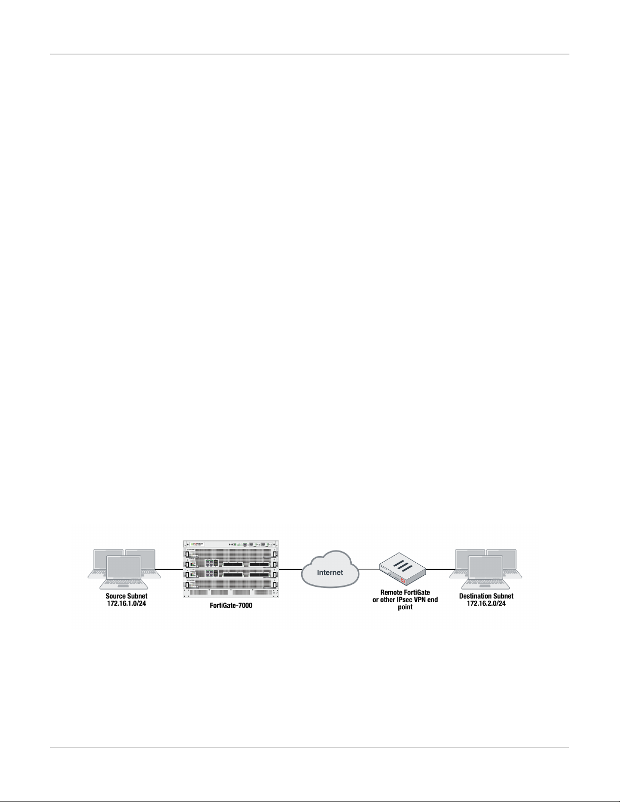
Adding source and destination subnets to IPsec VPN phase 2 configurations IPsec VPN
IPsec VPN
Adding source and destination subnets to IPsec VPN phase 2 configurations
If your FortiGate-7000 configuration includes IPsec VPNs you should enhance your IPsec VPN Phase 2
configurations as described in this section. If your FortiGate-7000 does not include IPsec VPNs you can proceed
with a normal firmware upgrade.
Because the FortiGate-7000 only allows 16-bit to 32-bit routes, you must add one or more destination subnets to
your IPsec VPN phase 2 configuration for FortiGate-7000 v5.4.5 using the following command:
config vpn ipsec phase2-interface
edit "to_fgt2"So
set phase1name <name>
set src-subnet <IP> <netmask>
set dst-subnet <IP> <netmask>
end
Where
src-subnet is the subnet protected by the FortiGate that you are configuring and from which users connect to
the destination subnet. Configuring the source subnet is optional but recommended.
dst-subnet is the destination subnet behind the remote IPsec VPNendpoint. Configuring the destination
subnet is required.
You can add the source and destination subnets either before or after upgrading to v5.4.5 as these settings are
compatible with both v5.4.3 and v5.4.5. However, if you make these changes after upgrading, your IPsec VPNs
may not work correctly until these configuration changes are made.
Example basic IPsec VPN Phase 2 configuration
In a simple configuration such as the one below with an IPsec VPN between two remote subnets you can just add
the subnets to the phase 2 configuration.
Enter the following command to add the source and destination subnets to the FortiGate-7000 IPsec VPN Phase
2 configuration.
config vpn ipsec phase2-interface
edit "to_fgt2"So
set phase1name "to_fgt2"
set src-subnet 172.16.1.0 255.255.255.0
51 FortiGate-7000
Fortinet Technologies Inc.
Page 52

IPsec VPN Adding source and destination subnets to IPsec VPN phase 2 configurations
set dst-subnet 172.16.2.0 255.255.255.0
end
Example multiple subnet IPsec VPN Phase 2 configuration
In a more complex configuration, such as the one below with a total of 5 subnets you still need to add all of the
subnets to the Phase 2 configuration. In this case you can create a firewall address for each subnet and the
addresses to address groups and add the address groups to the Phase 2 configuration.
Enter the following commands to create firewall addresses for each subnet.
config firewall address
edit "local_subnet_1"
set subnet 4.2.1.0 255.255.255.0
next
edit "local_subnet_2"
set subnet 4.2.2.0 255.255.255.0
next
edit "remote_subnet_3"
set subnet 4.2.3.0 255.255.255.0
next
edit "remote_subnet_4"
set subnet 4.2.4.0 255.255.255.0
next
edit "remote_subnet_5"
set subnet 4.2.5.0 255.255.255.0
end
And then put the five firewall addresses into two firewall address groups.
config firewall addrgrp
edit "local_group"
set member "local_subnet_1" "local_subnet_2"
next
edit "remote_group"
set member "remote_subnet_3" "remote_subnet_4" "remote_subnet_5"
end
Now, use the firewall address groups in the Phase 2 configuration:
FortiGate-7000
Fortinet Technologies Inc.
52
Page 53

Configuring the FortiGate-7000 as a dialup IPsec VPN server IPsec VPN
config vpn ipsec phase2-interface
edit "to-fgt2"
set phase1name "to-fgt2"
set src-addr-type name
set dst-addr-type name
set src-name "local_group"
set dst-name "remote_group"
end
Configuring the FortiGate-7000 as a dialup IPsec VPN server
FortiGate-7000s running v5.4.5 can be configured as dialup IPsec VPN servers.
Example dialup IPsec VPN configuration
The following shows how to setup a dialup IPsec VPN configuration where the FortiGate-7000 acts as a dialup
IPsec VPN server.
To configure the FortiGate-7000 as a dialup IPsec VPN server:
Configure the phase1, set type to dynamic.
config vpn ipsec phase1-interface
edit dialup-server
set type dynamic
set interface "v0020"
set peertype any
set psksecret <password>
end
Configure the phase 2, to support dialup IPsec VPN, set the destination subnet to 0.0.0.0 0.0.0.0.
config vpn ipsec phase2-interface
edit dialup-server
set phase1name dialup-server
set src-subnet 4.2.0.0 255.255.0.0
set dst-subnet 0.0.0.0 0.0.0.0
end
53 FortiGate-7000
Fortinet Technologies Inc.
Page 54

IPsec VPN Troubleshooting
To configure the remote FortiGate as a dialup IPsec VPN client
The dialup IPsec VPN client should advertise its local subnet(s) using the phase 2 src-subnet option.
If there are multiple local subnets create a phase 2 for each one. Each phase 2 only
advertises one local subnet to the dialup IPsec VPN server. If more than one local
subnet is added to the phase 2, only the first one is advertised to the server.
Dialup client configuration:
config vpn ipsec phase1-interface
edit "to-fgt7k"
set interface "v0020"
set peertype any
set remote-gw 1.2.0.1
set psksecret <password>
end
config vpn ipsec phase2-interface
edit "to-fgt7k"
set phase1name "to-fgt7k"
set src-subnet 4.2.6.0 255.255.255.0
set dst-subnet 4.2.0.0 255.255.0.0
next
edit "to-fgt7k-2"
set phase1name "to-fgt7k"
set src-subnet 4.2.7.0 255.255.255.0
set dst-subnet 4.2.0.0 255.255.0.0
end
Troubleshooting
Use the following commands to verify that IPsec VPN sessions are up and running.
Use the diagnose load-balance status command from the primary FIM interface module to determine
the primary FPM processor module. For FortiGate-7000 HA, run this command from the primary FortiGate-7000.
The third line of the command output shows which FPMis operating as the primary FPM.
diagnose load-balance status
FIM01: FIM04E3E16000074
Master FPM Blade: slot-4
Slot 3: FPM20E3E17900113
Status:Working Function:Active
Link: Base: Up Fabric: Up
Heartbeat: Management: Good Data: Good
Status Message:"Running"
Slot 4: FPM20E3E16800033
Status:Working Function:Active
Link: Base: Up Fabric: Up
Heartbeat: Management: Good Data: Good
Status Message:"Running"
FortiGate-7000
Fortinet Technologies Inc.
54
Page 55

Troubleshooting IPsec VPN
FIM02: FIM10E3E16000040
Master FPM Blade: slot-4
Slot 3: FPM20E3E17900113
Status:Working Function:Active
Link: Base: Up Fabric: Up
Heartbeat: Management: Good Data: Good
Status Message:"Running"
Slot 4: FPM20E3E16800033
Status:Working Function:Active
Link: Base: Up Fabric: Up
Heartbeat: Management: Good Data: Good
Status Message:"Running"
Log into the primary FPM CLI and run the command diagnose vpn tunnel list <phase2> to show the sessions for
the phase 2 configuration. The example below is for the to-fgt2 phase 2 configuration configured previously in
this chapter. The command output shows the security association (SA) setup for this phase 2 and the all of the
destination subnets .
Make sure the SA is installed (In blue color). And the “dst” are correct (in red color).
CH15 [FPM04] (002ipsecvpn) # diagnose vpn tunnel list name to-fgt2
list ipsec tunnel by names in vd 11
-----------------------------------------------------name=to-fgt2 ver=1 serial=2 4.2.0.1:0->4.2.0.2:0
bound_if=199 lgwy=static/1 tun=intf/0 mode=auto/1 encap=none/40 options[0028]=npu
ike_assit
proxyid_num=1 child_num=0 refcnt=8581 ilast=0 olast=0 auto-discovery=0
ike_asssit_last_sent=4318202512
stat: rxp=142020528 txp=147843214 rxb=16537003048 txb=11392723577
dpd: mode=on-demand on=1 idle=20000ms retry=3 count=0 seqno=2
natt: mode=none draft=0 interval=0 remote_port=0
proxyid=to-fgt2 proto=0 sa=1 ref=8560 serial=8
src: 0:4.2.1.0/255.255.255.0:0 0:4.2.2.0/255.255.255.0:0
dst: 0:4.2.3.0/255.255.255.0:0 0:4.2.4.0/255.255.255.0:0
0:4.2.5.0/255.255.255.0:0
SA: ref=7 options=22e type=00 soft=0 mtu=9134 expire=42819/0B replaywin=2048
seqno=4a26f esn=0 replaywin_lastseq=00045e80
life: type=01 bytes=0/0 timeout=43148/43200
dec: spi=e89caf36 esp=aes key=16 26aa75c19207d423d14fd6fef2de3bcf
ah=sha1 key=20 7d1a330af33fa914c45b80c1c96eafaf2d263ce7
enc: spi=b721b907 esp=aes key=16 acb75d21c74eabc58f52ba96ee95587f
ah=sha1 key=20 41120083d27eb1d3c5c5e464d0a36f27b78a0f5a
dec:pkts/bytes=286338/40910978, enc:pkts/bytes=562327/62082855
npu_flag=03 npu_rgwy=4.2.0.2 npu_lgwy=4.2.0.1 npu_selid=b dec_npuid=3 enc_
npuid=1
Log into the CLIof any of the FIMmodules and run the command diagnose test application
fctrlproxyd 2. The output should show matching destination subnets.
55 FortiGate-7000
Fortinet Technologies Inc.
Page 56

IPsec VPN Troubleshooting
diagnose test application fctrlproxyd 2
fcp route dump : last_update_time 24107
Slot:4
routecache entry: (5)
checksum:27 AE 00 EA 10 8D 22 0C D6 48 AB 2E 7E 83 9D 24
vd:3 p1:to-fgt2 p2:to-fgt2 subnet:4.2.3.0 mask:255.255.255.0 enable:1
vd:3 p1:to-fgt2 p2:to-fgt2 subnet:4.2.4.0 mask:255.255.255.0 enable:1
vd:3 p1:to-fgt2 p2:to-fgt2 subnet:4.2.5.0 mask:255.255.255.0 enable:1
=========================================
FortiGate-7000
Fortinet Technologies Inc.
56
Page 57

Before you begin configuring HA High Availability
High Availability
FortiGate-7000 supports a variation of active-passive FortiGate Clustering Protocol (FGCP) high availability
between two identical FortiGate-7000 chassis. With active-passive FortiGate-7000 HA, you create redundant
network connections to two identical FortiGate-7000s and add redundant HA heartbeat connections. Then you
configure the FIMinterface modules for HA. A cluster forms and a primary chassis is selected.
Example FortiGate-7040
All traffic is processed by the primary (or master) chassis. The backup chassis operates in hot standby mode. The
configuration, active sessions, routing information, and so on is synchronized to the backup chassis. If the
primary chassis fails, traffic automatically fails over to the backup chassis.
The primary chassis is selected based on a number of criteria including the configured priority, the bandwidth, the
number of FIM interface failures, and the number of FPM or FIM modules that have failed. As part of the HA
configuration you assign each chassis a chassis ID and you can set the priority of each FIM interface module and
configure module failure tolerances and the link failure thresholds.
Before you begin configuring HA
Before you begin, the chassis should be running the same FortiOS firmware version and interfaces should not be
configured to get their addresses from DHCP or PPPoE. Register and apply licenses to the each FortiGate-7000
57 FortiGate-7000
Fortinet Technologies Inc.
Page 58

High Availability Connect the M1 and M2 interfaces for HA heartbeat communication
before setting up the HA cluster. This includes licensing for FortiCare, IPS, AntiVirus, Web Filtering, Mobile
Malware, FortiClient, FortiCloud, and additional virtual domains (VDOMs). Both FortiGate-7000s in the cluster
must have the same level of licensing for FortiGuard, FortiCloud, FortiClient, and VDOMs. FortiToken licenses
can be added at any time because they are synchronized to all cluster members.
If required, you should configure split ports on the FIMs on both chassis before configuring HA because the
modules have to reboot after split ports is configured. For example, to split the C1, C2, and C4 interfaces of an
FIM-7910E in slot 1, enter the following command:
config system global
set split-port 1-C1 2-C1 2-C4
end
After configuring split ports, the chassis reboots and the configuration is synchronized.
On each chassis, make sure configurations of the modules are synchronized before starting to configure HA. You
can use the following command to verify that the configurations of all of the modules are synchronized:
diagnose sys confsync chsum | grep all
all: c0 68 d2 67 e1 23 d9 3a 10 50 45 c5 50 f1 e6 8e
all: c0 68 d2 67 e1 23 d9 3a 10 50 45 c5 50 f1 e6 8e
all: c0 68 d2 67 e1 23 d9 3a 10 50 45 c5 50 f1 e6 8e
all: c0 68 d2 67 e1 23 d9 3a 10 50 45 c5 50 f1 e6 8e
all: c0 68 d2 67 e1 23 d9 3a 10 50 45 c5 50 f1 e6 8e
all: c0 68 d2 67 e1 23 d9 3a 10 50 45 c5 50 f1 e6 8e
all: c0 68 d2 67 e1 23 d9 3a 10 50 45 c5 50 f1 e6 8e
all: c0 68 d2 67 e1 23 d9 3a 10 50 45 c5 50 f1 e6 8e
If the modules are synchronized, the checksums displayed should all be the same.
You can also use the following command to list the modules that are synchronized. The example output shows all
four FIM modules have been configured for HA and added to the cluster.
diagnose sys configsync status | grep in_sync
Master, uptime=692224.19, priority=1, slot_1d=1:1, idx=0, flag=0x0, in_sync=1
Slave, uptime=676789.70, priority=2, slot_1d=1:2, idx=1, flag=0x0, in_sync=1
Slave, uptime=692222.01, priority=17, slot_1d=1:4, idx=2, flag=0x64, in_sync=1
Slave, uptime=692271.30, priority=16, slot_1d=1:3, idx=3, flag=0x64, in_sync=1
In this command output in_sync=1 means the module is synchronized with the primary unit and in_sync=0 means
the module is not synchronized.
Connect the M1 and M2 interfaces for HA heartbeat communication
HA heartbeat communication between chassis happens over the 10Gbit M1 and M2 interfaces of the FIM
modules in each chassis. To set up HA heartbeat connections:
l Connect the M1 interfaces of all FIM modules together using a switch.
l Connect the M2 interfaces of all FIM modules together using another switch.
All of the M1 interfaces must be connected together with a switch and all of the M2 interfaces must be connected
together with another switch. Connecting M1 interfaces or M2 interfaces directly is not supported as each FIM
needs to communicate with all other FIMs.
FortiGate-7000
Fortinet Technologies Inc.
58
Page 59

Connect the M1 and M2 interfaces for HA heartbeat communication High Availability
Connect the M1 and M2 interfaces before enabling HA. Enabling HA moves heartbeat
communication between the FIM modules in the same chassis to the M1 and M2
interfaces. So if these interfaces are not connected before you enable HA, FIM
modules in the same chassis will not be able to communicate with each other.
Heartbeat packets are VLAN packets with VLAN ID 999 and ethertype 9890. The MTU value for the M1 and M2
interfaces is 1500. You can use the following commands to change the HA heartbeat packet VLAN ID and
ethertype values if required for your switches. You must change these settings on each FIM interface module. By
default the M1 and M2 interface heartbeat packets use the same VLAN IDs and ethertypes.
config system ha
set hbdev-vlan-id <vlan>
set hbdev-second-vlan-id <vlan>
set ha-eth-type <eth-type>
end
Using separate switches for M1 and M2 is recommended for redundancy. It is also
recommended that these switches be dedicated to HA heartbeat communication and
not used for other traffic.
If you use the same switch for both M1 and M2, separate the M1 and M2 traffic on the
switch and set the heartbeat traffic on the M1 and M2 Interfaces to have different
VLAN IDs. For example, use the following command to set the heartbeat traffic on M1
to use VLAN ID 777 and the heartbeat traffic on M2 to use VLAN ID 888:
config system ha
set hbdev-vlan-id 777
set hbdev-second-vlan-id 888
end
If you don't set different VLAN IDs for the M1 and M2 heartbeat packets q-in-q must be
enabled on the switch.
Sample switch configuration for a Cisco Catalyst switch. This configuration sets the interface speeds, configures
the switch to allow vlan 999, and enables trunk mode:
##interface config
interface TenGigabitEthernet1/0/5
description Chassis1 FIM1 M1
switchport trunk allowed vlan 999
switchport mode trunk
If you are using one switch for both M1 and M2 connections, the configuration would be the same except you
would add q-in-q support and two different VLANs, one for M1 traffic and one for M2 traffic.
59 FortiGate-7000
Fortinet Technologies Inc.
Page 60

High Availability HA configuration
For the M1 connections:
interface Ethernet1/5
description QinQ Test
switchportmode dot1q-tunnel
switchport access vlan 888
spanning-tree port type edge
For the M2 connections:
interface Ethernet1/5
description QinQ Test
switchport mode dot1q-tunnel
switchport access vlan 880
spanning-tree port type edge
HApackets must have the configured VLAN tag (default 999). If the switch removes or changes this tag, HA
heartbeat communication will not work and the cluster will form a split brain configuration. In effect two clusters
will form, one in each chassis, and network traffic will be disrupted.
HA configuration
Use the following steps to setup the configuration for HA between two chassis (chassis 1 and chassis 2). These
steps are written for a set of two FortiGate-7040E or 7060Es. The steps are similar for the FortiGate-7030E
except that each FortiGate-7030E only has one FIM interface module.
Each FIM interface module has to be configured for HA separately. The HA configuration is not synchronized
among FIMs. You can begin by setting up chassis 1 and setting up HA on both of the FIM interfaces modules in
it. Then do the same for chassis 2.
Each of the FortiGate-7000s is assigned a chassis ID (1 and 2). These numbers just allow you to identify the
chassis and do not influence primary unit selection.
Setting up HA on the FIM interface modules in the first FortiGate-7000 (chassis 1)
1.
Log into the CLI of the FIM interface module in slot 1 (FM01) and enter the following command:
config system ha
set mode a-p
set password <password>
set group-id <id>
set chassis-id 1
set hbdev M1/M2
end
This adds basic HAsettings to this FIM interface module.
2.
Repeat this configuration on the FIMinterface module in slot 2 (FIM02).
config system ha
set mode a-p
set password <password>
set group-id <id>
set chassis-id 1
set hbdev M1/M2
FortiGate-7000
Fortinet Technologies Inc.
60
Page 61

HA configuration High Availability
end
3.
From either FIM interface module, enter the following command to confirm that the FortiGate-7000 is in HA
mode:
diagnose sys ha status
The password and group-id are unique for each HA cluster and must be the same on all FIM modules.
If a cluster does not form, one of the first things to check are groupd-id and re-enter the password on both
FIMinterface modules.
Configure HA on the FIM interface modules in the second FortiGate-7000 (chassis 2)
1.
Repeat the same HA configuration settings on the FIM interfaces modules in the second chassis except set the
chassis ID to 2.
config system ha
set mode a-p
set password <password>
set group-id <id>
set chassis-id 2
set hbdev M1/M2
end
2.
From any FIM interface module, enter the following command to confirm that the cluster has formed and all of the
FIMmodules have been added to it:
diagnose sys ha status
The cluster has now formed and you can add the configuration and connect network equipment and start
operating the cluster. You can also modify the HA configuration depending on your requirements.
Verifying that the cluster is operating correctly
Enter the following CLI command to view the status of the cluster. You can enter this command from any
module's CLI. The HA members can be in a different order depending on the module CLIfrom which you enter
the command.
If the cluster is operating properly the following command output should indicate the primary and backup (master
and slave) chassis as well as primary and backup (master and slave)modules. For each module, the state
portion of the output shows all the parameters used to select the primary FIMmodule. These parameters include
the number FPM modules that the FIM module is connecting to that have failed, the status of any link
aggregation group (LAG) interfaces in the configuration, the state of the interfaces in the FIM module, the traffic
bandwidth score for the FIM module (the higher the traffic bandwidth score the more interfaces are connected to
networks, and the status of the management links.
diagnose sys ha status
==========================================================================
Current slot: 1 Module SN: FIM04E3E16000085
Chassis HA mode: a-p
Chassis HA information:
[Debug_Zone HA information]
HA group member information: is_manage_master=1.
FG74E83E16000015: Slave, serialno_prio=1, usr_priority=128, hostname=CH15
FG74E83E16000016: Master, serialno_prio=0, usr_priority=127, hostname=CH16
HA member information:
CH16(FIM04E3E16000085), Master(priority=0), uptime=78379.78, slot=1, chassis=2(2)
61 FortiGate-7000
Fortinet Technologies Inc.
Page 62

High Availability HA management configuration
slot: 1, chassis_uptime=145358.97,
more: cluster_id:0, flag:1, local_priority:0, usr_priority:127, usr_override:0
state: worker_failure=0/2, lag=(total/good/down/bad-score)=5/5/0/0,
intf_state=(port up)=0, force-state(1:force-to-master)
traffic-bandwidth-score=120, mgmt-link=1
hbdevs: local_interface= 1-M1 best=yes
local_interface= 1-M2 best=no
ha_elbc_master: 3, local_elbc_master: 3
CH15(FIM04E3E16000074), Slave(priority=2), uptime=145363.64, slot=1, chassis=1(2)
slot: 1, chassis_uptime=145363.64,
more: cluster_id:0, flag:0, local_priority:2, usr_priority:128, usr_override:0
state: worker_failure=0/2, lag=(total/good/down/bad-score)=5/5/0/0,
intf_state=(port up)=0, force-state(-1:force-to-slave)
traffic-bandwidth-score=120, mgmt-link=1
hbdevs: local_interface= 1-M1 last_hb_time=145640.39 status=alive
local_interface= 1-M2 last_hb_time=145640.39 status=alive
CH15(FIM10E3E16000040), Slave(priority=3), uptime=145411.85, slot=2, chassis=1(2)
slot: 2, chassis_uptime=145638.51,
more: cluster_id:0, flag:0, local_priority:3, usr_priority:128, usr_override:0
state: worker_failure=0/2, lag=(total/good/down/bad-score)=5/5/0/0,
intf_state=(port up)=0, force-state(-1:force-to-slave)
traffic-bandwidth-score=100, mgmt-link=1
hbdevs: local_interface= 1-M1 last_hb_time=145640.62 status=alive
local_interface= 1-M2 last_hb_time=145640.62 status=alive
CH16(FIM10E3E16000062), Slave(priority=1), uptime=76507.11, slot=2, chassis=2(2)
slot: 2, chassis_uptime=145641.75,
more: cluster_id:0, flag:0, local_priority:1, usr_priority:127, usr_override:0
state: worker_failure=0/2, lag=(total/good/down/bad-score)=5/5/0/0,
intf_state=(port up)=0, force-state(-1:force-to-slave)
traffic-bandwidth-score=100, mgmt-link=1
hbdevs: local_interface= 1-M1 last_hb_time=145640.39 status=alive
local_interface= 1-M2 last_hb_time=145640.39 status=alive
HA management configuration
In HA mode, you should connect the interfaces in the mgmt 802.3 static aggregate interfaces of both chassis to
the same switch. You can create one aggregate interface on the switch and connect both chassis management
interfaces to it.
LACPis not supported for the mgmt interface aggregate interface. The mgmt
interfaces are in a static aggregate interface.
FortiGate-7000
Fortinet Technologies Inc.
62
Page 63

Managing individual modules in HAmode High Availability
When you browse to the system management IP address you connect to the primary FIMinterface module in the
primary chassis. Only the primary FIM interface module responds to management connections using the system
management IP address. If a failover occurs you can connect to the new primary FIM interface module using the
same system management IP address.
Managing individual modules in HAmode
In some cases you may want to connect to an individual FIM or FPM module in a specific chassis. For example,
you may want to view the traffic being processed by the FPM module in slot 3 of chassis 2. You can connect to
the GUI or CLIof individual modules in the chassis using the system management IP address with a special port
number.
For example, if the system management IP address is 1.1.1.1 you can browse to https://1.1.1.1:44323 to
connect to the FPM module in chassis 2 slot 3. The special port number (in this case 44323)is a combination of
the service port, chassis ID, and slot number. The following table lists the special ports for common admin
protocols:
FortiGate-7000 HA special administration port numbers
Chassis and Slot Number Slot Address
Ch1 slot 5 FPM05 8005 44305 2305 2205 16105
Ch1 slot 3 FPM03 8005 44303 2303 2203 16103
Ch1 slot 1 FIM01 8003 44301 2301 2201 16101
Ch1 slot 2 FIM02 8002 44302 2302 2202 16102
Ch1 slot 4 FPM04 8004 44304 2304 2204 16104
Ch1 slot 6 FPM06 8006 44306 2306 2206 16106
Ch2 slot 5 FPM05 8005 44325 2325 2225 16125
Ch2 slot 3 FPM03 8005 44323 2323 2223 16123
Ch2 slot 1 FIM01 8003 44321 2321 2221 16121
Ch2 slot 2 FIM02 8002 44322 2322 2222 16122
Ch2 slot 4 FPM04 8004 44324 2324 2224 16124
HTTP
(80)
HTTPS (443)
Telnet
(23)
SSH (22) SNMP (161)
Ch2 slot 6 FPM06 8006 44326 2326 2226 16126
For example:
63 FortiGate-7000
Fortinet Technologies Inc.
Page 64

High Availability Firmware upgrade
l To connect to the GUI of the FPM module in chassis 1 slot 3 using HTTPS you would browse to
https://1.1.1.1:44313.
l To send an SNMP query to the FPM module in chassis 2 slot 6 use the port number 16126.
The formula for calculating the special port number is based on Chassis ID. CH1 =
Chassis ID1, CH2 = Chassis ID2. The formula is: service_port x 100 + (chassis_id – 1)
x 20 + slot_id.
Firmware upgrade
All of the modules in a FortiGate-7000 HA cluster run the same firmware image. You upgrade the firmware from
the GUIor CLI by logging into the primary FIMinterface module using the system management IP address and
uploading the firmware image.
If uninterruptable-upgrade and session-pickup are enabled, firmware upgrades should only cause a
minimal traffic interruption. Use the following command to enable these settings (they should be enabled by
default). These settings are synchronized to all modules in the cluster.
config system ha
set uninterruptable-upgrade enable
set session-pickup enable
end
When enabled, the primary FIM interface module uploads firmware to all modules, but in this case, the modules
in the backup chassis install their new firmware and reboot and rejoin the cluster and resynchronize.
Then all traffic fails over to the backup chassis which becomes the new primary chassis. Then the modules in the
new backup chassis upgrade their firmware and rejoin the cluster. Unless override is enabled, the new primary
chassis continues to operate as the primary chassis.
Normally you would want to enable uninterruptable-upgrade to minimize traffic interruptions. But
unterruptable-upgrade does not have to be enabled. In fact, if a traffic interruption is not going to cause
any problems you an disable unterruptable-upgrade so that the firmware upgrade process takes less time.
Session failover (session-pickup)
Session failover means that after a failover, communications sessions resume on the new primary FortiGate7000 with minimal or no interruption. Two categories of sessions need to be resumed after a failover:
l Sessions passing through the cluster
l Sessions terminated by the cluster
Session failover (also called session-pickup) is not enabled by default for FortiGate-7000 HA. If sessions pickup is
enabled, while the FortiGate-7000 HA cluster is operating the primary FortiGate-7000 informs the backup
FortiGate-7000 of changes to the primary FortiGate-7000 connection and state tables for TCP and UDP sessions
passing through the cluster, keeping the backup FortiGate-7000 up-to-date with the traffic currently being
processed by the cluster.
FortiGate-7000
Fortinet Technologies Inc.
64
Page 65

Session failover (session-pickup) High Availability
After a failover the new primary FortiGate-7000 recognizes open sessions that were being handled by the cluster.
The sessions continue to be processed by the new primary FortiGate-7000 and are handled according to their last
known state.
Session-pickup has some limitations. For example, session failover is not supported
for sessions being scanned by proxy-based security profiles. Session failover is
supported for sessions being scanned by flow-based security profiles; however, flowbased sessions that fail over are not inspected after they fail over.
Session terminated by the cluster include management sessions (such as HTTPS connections to the FortiGate
GUI or SSH connection to the CLI as well as SNMP and logging and so on). Also included in this category are
IPsec VPN, SSL VPN, sessions terminated by the cluster, and explicit proxy sessions. In general, whether or not
session-pickup is enabled, these sessions do not failover and have to be restarted.
Enabling session pickup for TCP and UDP
To enable session-pickup, from the CLI enter:
config system ha
set session-pickup enable
end
When session-pickup is enabled, sessions in the primary FortiGate-7000 TCP and UDP session tables are
synchronized to the backup FortiGate-7000. As soon as a new TCP or UDP session is added to the primary
FortiGate-7000 session table, that session is synchronized to the backup FortiGate-7000. This synchronization
happens as quickly as possible to keep the session tables synchronized.
If the primary FortiGate-7000 fails, the new primary FortiGate-7000 uses its synchronized session tables to
resume all TCP and UDP sessions that were being processed by the former primary FortiGate-7000 with only
minimal interruption. Under ideal conditions all TCP and UDP sessions should be resumed. This is not
guaranteed though and under less than ideal conditions some sessions may need to be restarted.
If session pickup is disabled
If you disable session pickup, the FortiGate-7000 HA cluster does not keep track of sessions and after a failover,
active sessions have to be restarted or resumed. Most session can be resumed as a normal result of how TCP
and UDP resumes communication after any routine network interruption.
The session-pickup setting does not affect session failover for sessions terminated by
the cluster.
If you do not require session failover protection, leaving session pickup disabled may reduce CPU usage and
reduce HA heartbeat network bandwidth usage. Also if your FortiGate-7000 HAcluster is mainly being used for
traffic that is not synchronized (for example, for proxy-based security profile processing) enabling session pickup
is not recommended since most sessions will not be failed over anyway.
65 FortiGate-7000
Fortinet Technologies Inc.
Page 66

High Availability Primary unit selection and failover criteria
Primary unit selection and failover criteria
Once two FortiGate-7000s recognize that they can form a cluster, they negotiate to select a primary chassis.
Primary selection occurs automatically based on the criteria shown below. After the cluster selects the primary,
the other chassis becomes the backup.
Negotiation and primary chassis selection also takes place if the one of the criteria for selecting the primary
chassis changes. For example, an interface can become disconnected or module can fail. After this happens, the
cluster can renegotiate to select a new primary chassis also using the criteria shown below.
FortiGate-7000
Fortinet Technologies Inc.
66
Page 67

Primary unit selection and failover criteria High Availability
67 FortiGate-7000
Fortinet Technologies Inc.
Page 68

High Availability How link and module failures affect primary chassis selection
If there are no failures and if you haven't configured any settings to influence primary chassis selection, the
chassis with the highest serial number to becomes the primary chassis.
Using the serial number is a convenient way to differentiate FortiGate-7000 chassis; so basing primary chassis
selection on the serial number is predictable and easy to understand and interpret. Also the chassis with the
highest serial number would usually be the newest chassis with the most recent hardware version. In many cases
you may not need active control over primary chassis selection, so basic primary chassis selection based on serial
number is sufficient.
In some situations you may want have control over which chassis becomes the primary chassis. You can control
primary chassis selection by setting the priority of one chassis to be higher than the priority of the other. If you
change the priority of one of the chassis, during negotiation, the chassis with the highest priority becomes the
primary chassis. As shown above, FortiGate-7000 FGCP selects the primary chassis based on priority before
serial number. For more information about how to use priorities, see High Availability on page 57.
Chassis uptime is also a factor. Normally when two chassis start up their uptimes are similar and do not affect
primary chassis selection. However, during operation, if one of the chassis goes down the other will have a much
higher uptime and will be selected as the primary chassis before priorty and serial number are tested.
Verifying primary chassis selection
You can use the diagnose sys ha status command to verify which chassis has become the primary
chassis as shown by the following command output example. This output also shows that the chassis with the
highest serial number was selected to be the primary chassis.
diagnose sys ha status
==========================================================================
Current slot: 1 Module SN: FIM04E3E16000085
Chassis HA mode: a-p
Chassis HA information:
[Debug_Zone HA information]
HA group member information: is_manage_master=1.
FG74E83E16000015: Slave, serialno_prio=1, usr_priority=128, hostname=CH15
FG74E83E16000016: Master, serialno_prio=0, usr_priority=127, hostname=CH16
How link and module failures affect primary chassis selection
The total number of connected data interfaces in a chassis has a higher priority than the number of failed
modules in determining which chassis in a FortiGate-7000 HA configuration is the primary chassis. For example,
if one chassis has a failed FPM module and the other has a disconnected or failed data interface, the chassis with
the failed processor module becomes the primary unit.
For another example, the following diagnose sys ha status command shows the HA status for a cluster
where one chassis has a disconnected or failed data interface and the other chassis has a failed FPMmodule.
diagnose sys ha status
==========================================================================
Slot: 2 Module SN: FIM01E3E16000088
Chassis HA mode: a-p
Chassis HA information:
FortiGate-7000
Fortinet Technologies Inc.
68
Page 69

How link and module failures affect primary chassis selection High Availability
[Debug_Zone HA information]
HA group member information: is_manage_master=1.
FG74E33E16000027: Master, serialno_prio=0, usr_priority=128, hostname=Chassis-K
FG74E13E16000072: Slave, serialno_prio=1, usr_priority=128, hostname=Chassis-J
HA member information:
Chassis-K(FIM01E3E16000088), Slave(priority=1), uptime=2237.46, slot=2, chassis=1(1)
slot: 2, chassis_uptime=2399.58,
state: worker_failure=1/2, lag=(total/good/down/bad-score)=2/2/0/0,
intf_state=(port up)=0, force-state(0:none)
traffic-bandwidth-score=20, mgmt-link=1
hbdevs: local_interface= 2-M1 best=yes
local_interface= 2-M2 best=no
Chassis-J(FIM01E3E16000031), Slave(priority=2), uptime=2151.75, slot=2, chassis=2(1)
slot: 2, chassis_uptime=2151.75,
state: worker_failure=0/2, lag=(total/good/down/bad-score)=2/2/0/0,
intf_state=(port up)=0, force-state(0:none)
traffic-bandwidth-score=20, mgmt-link=1
hbdevs: local_interface= 2-M1 last_hb_time= 2399.81 status=alive
local_interface= 2-M2 last_hb_time= 0.00 status=dead
Chassis-J(FIM01E3E16000033), Slave(priority=3), uptime=2229.63, slot=1, chassis=2(1)
slot: 1, chassis_uptime=2406.78,
state: worker_failure=0/2, lag=(total/good/down/bad-score)=2/2/0/0,
intf_state=(port up)=0, force-state(0:none)
traffic-bandwidth-score=20, mgmt-link=1
hbdevs: local_interface= 2-M1 last_hb_time= 2399.81 status=alive
local_interface= 2-M2 last_hb_time= 0.00 status=dead
Chassis-K(FIM01E3E16000086), Master(priority=0), uptime=2203.30, slot=1, chassis=1(1)
slot: 1, chassis_uptime=2203.30,
state: worker_failure=1/2, lag=(total/good/down/bad-score)=2/2/0/0,
intf_state=(port up)=1, force-state(0:none)
traffic-bandwidth-score=30, mgmt-link=1
hbdevs: local_interface= 2-M1 last_hb_time= 2399.74 status=alive
local_interface= 2-M2 last_hb_time= 0.00 status=dead
This output shows that chassis 1 (hostname Chassis-K) is the primary or master chassis. The reason for this is
that chassis 1 has a total traffic-bandwidth-score of 30 + 20 = 50, while the total traffic-
bandwidth-score for chassis 2 (hostname Chassis-J) is 20 + 20 = 40.
The output also shows that both FIM modules in chassis 1 are detecting a worker failure (worker_
failure=1/2) while both FIM modules in chassis 2 are not detecting a worker failure worker_
failure=0/2). The intf-state=(port up)=1 field shows that FIM module in slot 1 of chassis 1 has one
more interface connected than the FIM module in slot 1 of chassis 2. It is this extra connected interface that gives
the FIM module in chassis 1 slot 1 the higher traffic bandwidth score than the FIM module in slot 1 of chassis 2.
One of the interfaces on the FIMmodule in slot 1 of chassis 2 must have failed. In a normal HA configuration the
FIM modules in matching slots of each chassis should have redundant interface connections. So if one module
has fewer connected interfaces this indicates a link failure.
69 FortiGate-7000
Fortinet Technologies Inc.
Page 70

High Availability Link failure threshold and board failover tolerance
FIM module failures
If an FIMmodule fails, not only will HA recognize this as a module failure it will also give the chassis with the
failed FIM module a much lower traffic bandwidth score. So an FIMmodule failure would be more likely to cause
an HA failover than a FPM module failover.
Also, the traffic bandwidth score for an FIM module with more connected interfaces would be higher than the
score for an FIMmodule with fewer connected interfaces. So if a different FIMmodule failed in each chassis, the
chassis with the functioning FIM module with the most connected data interfaces would have the highest traffic
bandwidth score and would become the primary chassis.
Management link failures
Management connections to a chassis can affect primary chassis selection. If the management connection to
one chassis become disconnected a failover will occur and the chassis that still has management connections will
become the primary chassis.
Link failure threshold and board failover tolerance
The default settings of the link failure threshold and the board failover tolerance result in the default link and
module failure behavior. You can change these settings if you want to modify this behavior. For example, if you
want a failover to occur if an FPM module fails, even if an interface has failed you can increase the board failover
tolerance setting.
Link failure threshold
The link failure threshold determines how many interfaces in a link aggregation interface (LAG) can be lost before
the LAG interface is considered down. The chassis with the most connected LAGs becomes the primary chassis.
if a LAG goes down the cluster will negotiate and may select a new primary chassis. You can use the following
command to change the link failure threshold:
config system ha
set link-failure-threshold <threshold>
end
The threshold range is 0 to 80 and 0 is the default.
A threshold of 0 means that if a single interface in any LAG fails the LAG the considered down. A higher failure
threshold means that more interfaces in a LAG can fail before the LAGis considered down. For example, if the
threshold is set to 1, at least two interfaces will have to fail.
Board failover tolerance
You can use the following command to configure board failover tolerance.
config system ha
set board-failover-tolerance <tolerance>
end
The tolerance range is 0 to 12, and 0 is the default.
FortiGate-7000
Fortinet Technologies Inc.
70
Page 71

Priority and primary chassis selection High Availability
A tolerance of 0 means that if a single module fails in the primary chassis a failover occurs and the chassis with
the fewest failed modules becomes the new primary chassis. A higher failover tolerance means that more
modules can fail before a failover occurs. For example, if the tolerance is set to 1, at least two modules in the
primary chassis will have to fail before a failover occurs.
Priority and primary chassis selection
You can select a chassis to become the primary chassis by setting the HA priority of one of one or more of its FIM
modules (for example, the FIM module in slot 1) higher than the priority of the other FIM modules. Enter the
following command to set the HA priority:
config system ha
set priority <number>
end
The default priority is 128.
The chassis with the highest total FIM module HA priority becomes the primary chassis.
Override and primary chassis selection
Enabling override changes the order of primary chassis selection. If override is enabled, primary chassis
selection considers priority before chassis up tme and serial number. This means that if you set the device priority
higher for one chassis, with override enabled this chassi becomes the primary chassis even if its uptime and
serial number are lower than the other chassis.
Enter the following command to enable override.
config system ha
set override enable
end
When override is enabled primary unit selection checks the traffic bandwidth score, aggregate interface state,
management interface links and FPM module failures first. So any of these factors affect primary chassis
selection, even if override is enabled.
71 FortiGate-7000
Fortinet Technologies Inc.
Page 72

FortiGate-7000 v5.4.5 special features and limitations Managing the FortiGate-7000
FortiGate-7000 v5.4.5 special features and limitations
This section describes special features and limitations for FortiGate-7000 v5.4.5.
Managing the FortiGate-7000
Management is only possible through the MGMT1 to MGMT4 front panel management interfaces. By default the
MGMT1 to MGMT4 interfaces of the FIM modules in slot 1 and slot 2 are in a single static aggregate interface
named mgmt with IPaddress 192.168.1.99. You manage the FortiGate-7000 by connecting any one of these
eight interfaces to your network, opening a web browser and browsing to https://192.168.1.99.
The FortiGate-7030E has one FIM module and the MGMT1 to MGMT4 interfaces of
that module are the only ones in the aggregate interface.
Default management VDOM
By default the FortiGate-7000 configuration includes a management VDOMnamed dmgmt-vdom. For the
FortiGate-7000 system to operate normally you should not change the configuration of this VDOM and this
VDOM should always be the management VDOM. You should also not add or remove interfaces from this
VDOM.
You have full control over the configurations of other FortiGate-7000 VDOMs.
Firewall
TCP sessions with NAT enabled that are expected to be idle for more than the distributed processing normal TCP
timer (which is 3605 seconds) should only be distributed to the master FPM using a flow rule. You can configure
the distributed normal TCP timer using the following command:
config system global
set dp-tcp-normal-timer <timer>
end
UDP sessions with NAT enabled that are expected to be idle for more than the distributed processing normal UDP
timer should only be distributed to the primary FPM using a flow rule.
IP Multicast
IPv4 and IPv6 Multicast traffic is only sent to the primary FPM module (usually the FPMin slot 3). This is
controlled by the following configuration:
config load-balance flow-rule
edit 18
FortiGate-7000
Fortinet Technologies Inc.
72
Page 73

HighAvailability FortiGate-7000 v5.4.5 special features and limitations
set status enable
set vlan 0
set ether-type ipv4
set src-addr-ipv4 0.0.0.0 0.0.0.0
set dst-addr-ipv4 224.0.0.0 240.0.0.0
set protocol any
set action forward
set forward-slot master
set priority 5
set comment "ipv4 multicast"
next
edit 19
set status enable
set vlan 0
set ether-type ipv6
set src-addr-ipv6 ::/0
set dst-addr-ipv6 ff00::/8
set protocol any
set action forward
set forward-slot master
set priority 5
set comment "ipv6 multicast"
end
HighAvailability
Only the M1 and M2 interfaces are used for the HAheartbeat communication.
When using both M1 and M2 for the heartbeat, FortiGate-7000 v5.4.5 requires two switches. The first switch to
connect all M1 ports together. The second second switch to connect all M2 ports together. This is because the
same VLAN is used for both M1 and M2 and the interface groups should remain in different broadcast domains.
Using a single switch for both M1 and M2 heartbeat traffic is possible if the switch supports q-in-q tunneling. In
this case use different VLANs for M1 traffic and M2 traffic to keep two separated broadcast domains in the switch.
The following FortiOS HA features are not supported or are supported differently by FortiGate-7000 v5.4.5:
l Remote IP monitoring (configured with the option pingserver-monitor-interface and related settings) is
not supported
l Active-active HA is not supported
l The range for the HA group-id is 0 to 14.
l Failover logic for FortiGate-7000 v5.4.5 HAis not the same as FGSP for other FortiGate clusters.
l HA heartbeat configuration is specific to FortiGate-7000 systems and differs from standard HA.
l FortiGate Session Life Support Procotol (FGSP) HA (also called standalone session synchronization) is not
supported.
Shelf Manager Module
It is not possible to access SMM CLI using Telnet or SSH. Only console access is supported using the chassis
front panel console ports as described in the FortiGate-7000 system guide.
73 FortiGate-7000
Fortinet Technologies Inc.
Page 74

FortiGate-7000 v5.4.5 special features and
FortiOS features that are not supported by FortiGate-7000
limitations
For monitoring purpose, IPMI over IP is supported on SMM Ethernet ports. See your FortiGate-7000 system
guide for details.
FortiOS features that are not supported by FortiGate-7000 v5.4.5
The following mainstream FortiOS 5.4.5 features are not supported by the FortiGate-7000 v5.4.5:
l Hardware switch
l Switch controller
l WiFi controller
l WAN load balancing (SD-WAN)
l IPv4 over IPv6, IPv6 over IPv4, IPv6 over IPv6 features
l GRE tunneling is only supported after creating a load balance flow rule, for example:
config load-balance flow-rule
edit 0
set status enable
set vlan 0
set ether-type ip
set protocol gre
set action forward
set forward-slot master
set priority 3
end
l Hard disk features including, WAN optimization, web caching, explicit proxy content caching, disk logging, and GUI-
based packet sniffing.
l Log messages should be sent only using the management aggregate interface
v5.4.5
IPsec VPN tunnels terminated by the FortiGate-7000
This section lists FortiGate-7000 limitations for IPsec VPN tunnels terminated by the FortiGate-7000:
l Interface-based IPsec VPN is recommended.
l Policy based IPsec VPN is supported, but requires creating flow-rules for each Phase 2 selector.
l Dynamic routing and policy routing is not supported for IPsec interfaces.
l IPsec static routes don't consider distance, weight, priority settings. IPsec static routes are always installed in the
routing table, regardless of the tunnel state.
l IPsec tunnels are not load-balanced across the FPMs, all IPsec tunnel sessions are sent to the primary FPM
module.
l IPsec VPN dialup or dynamic tunnels require a flow rule that sends traffic destined for IPsec dialup IP pools to the
primary FPM module.
l In an HA configuration, IPsec SAs are not synchronized to the backup chassis. IPsec SAs are re-negociated after a
failover.
FortiGate-7000
Fortinet Technologies Inc.
74
Page 75

SSL VPN FortiGate-7000 v5.4.5 special features and limitations
SSL VPN
Sending all SSL VPN sessions to the primary FPM module is recommended. You can do this by:
l Creating a flow rule that sends all sessions that use the SSL VPN destination port and IP address to the primary
FPM module.
l Creating flow rules that send all sessions that use the SSL VPN IP pool addresses to the primary FPM module.
Traffic shaping and DDoS policies
Each FPM module applies traffic shaping and DDoS quotas independently. Because of load-balancing, this may
allow more traffic than expected.
Sniffer mode (one-arm sniffer)
One-arm sniffer mode is only supported after creating a load balance flow rule to direct sniffer traffic to a specific
FPM module.
FortiGuard Web Filtering
All FortiGuard rating queries are sent through management aggregate interface from the management VDOM
(named dmgmt-vdom).
Log messages include a slot field
An additional "slot" field has been added to log messages to identify the FPM module that generated the log.
FortiOS Carrier
You have to apply a FortiOS Carrier license separately to each FIM and FPMmodule to license a FortiGate-7000
chassis for FortiOS Carrier.
Special notice for new deployment connectivity testing
Only the primary FPM module can successfully ping external IP addresses. During a new deployment, while
performing connectivity testing from the Fortigate-7000, make sure to run execute ping tests from the
primary FPM module CLI.
75 FortiGate-7000
Fortinet Technologies Inc.
Page 76

FortiGate-7000 v5.4.5 special features and limitations Special notice for new deployment connectivity testing
FortiGate-7000
Fortinet Technologies Inc.
76
Page 77

Managing the FortiGate-7000 FortiGate-7000 v5.4.3 special features and limitations
FortiGate-7000 v5.4.3 special features and limitations
This section describes special features and limitations for FortiGate-7000 v5.4.3.
Managing the FortiGate-7000
Management is only possible through the MGMT1 to MGMT4 front panel management interfaces. By default the
MGMT1 to MGMT4 interfaces of the FIM modules in slot 1 and slot 2 are in a single static aggregate interface
named mgmt with IPaddress 192.168.1.99. You manage the FortiGate-7000 by connecting any one of these
eight interfaces to your network, opening a web browser and browsing to https://192.168.1.99.
The FortiGate-7030E has one FIM module and the MGMT1 to MGMT4 interfaces of
that module are the only ones in the aggregate interface.
Default management VDOM
By default the FortiGate-7000 configuration includes a management VDOMnamed dmgmt-vdom. For the
FortiGate-7000 system to operate normally you should not change the configuration of this VDOM and this
VDOM should always be the management VDOM. You should also not add or remove interfaces from this
VDOM.
You have full control over the configurations of other FortiGate-7000 VDOMs.
Firewall
TCP sessions with NAT enabled that are expected to be idle for more than the distributed processing normal TCP
timer (which is 3605 seconds) should only be distributed to the master FPM using a flow rule. You can configure
the distributed normal TCP timer using the following command:
config system global
set dp-tcp-normal-timer <timer>
end
UDP sessions with NAT enabled that are expected to be idle for more than the distributed processing normal UDP
timer should only be distributed to the primary FPM using a flow rule.
Link monitoring and health checking
ICMP-based link monitoring for SD-WAN, ECMP, HA link monitoring, and firewall session load balancing
monitoring (or health checking) is not supported. Using TCPor UDP options for link monitoring instead.
77 FortiGate-7000
Fortinet Technologies Inc.
Page 78

FortiGate-7000 v5.4.3 special features and limitations IP Multicast
IP Multicast
IPv4 and IPv6 Multicast traffic is only sent to the primary FPM module (usually the FPMin slot 3). This is
controlled by the following configuration:
config load-balance flow-rule
edit 18
set status enable
set vlan 0
set ether-type ipv4
set src-addr-ipv4 0.0.0.0 0.0.0.0
set dst-addr-ipv4 224.0.0.0 240.0.0.0
set protocol any
set action forward
set forward-slot master
set priority 5
set comment "ipv4 multicast"
next
edit 19
set status enable
set vlan 0
set ether-type ipv6
set src-addr-ipv6 ::/0
set dst-addr-ipv6 ff00::/8
set protocol any
set action forward
set forward-slot master
set priority 5
set comment "ipv6 multicast"
end
HighAvailability
Only the M1 and M2 interfaces are used for the HAheartbeat communication.
When using both M1 and M2 for the heartbeat, FortiGate-7000 v5.4.3 requires two switches. The first switch to
connect all M1 ports together. The second second switch to connect all M2 ports together. This is because the
same VLAN is used for both M1 and M2 and the interface groups should remain in different broadcast domains.
Using a single switch for both M1 and M2 heartbeat traffic is possible if the switch supports q-in-q tunneling. In
this case use different VLANs for M1 traffic and M2 traffic to keep two separated broadcast domains in the switch.
The following FortiOS HA features are not supported or are supported differently by FortiGate-7000 v5.4.3:
l Remote IP monitoring (configured with the option pingserver-monitor-interface and related settings) is
not supported
l Active-active HA is not supported
l The range for the HA group-id is 0 to 14.
l Failover logic for FortiGate-7000 v5.4.3 HAis not the same as FGSP for other FortiGate clusters.
l HA heartbeat configuration is specific to FortiGate-7000 systems and differs from standard HA.
FortiGate-7000
Fortinet Technologies Inc.
78
Page 79

Shelf Manager Module FortiGate-7000 v5.4.3 special features and limitations
l FortiGate Session Life Support Procotol (FGSP) HA (also called standalone session synchronization) is not
supported.
Shelf Manager Module
It is not possible to access SMM CLI using Telnet or SSH. Only console access is supported using the chassis
front panel console ports as described in the FortiGate-7000 system guide.
For monitoring purpose, IPMI over IP is supported on SMM Ethernet ports. See your FortiGate-7000 system
guide for details.
FortiOS features that are not supported by FortiGate-7000 v5.4.3
The following mainstream FortiOS 5.4.3 features are not supported by the FortiGate-7000 v5.4.3:
l Hardware switch
l Switch controller
l WiFi controller
l WAN load balancing (SD-WAN)
l IPv4 over IPv6, IPv6 over IPv4, IPv6 over IPv6 features
l GRE tunneling is only supported after creating a load balance flow rule, for example:
config load-balance flow-rule
edit 0
set status enable
set vlan 0
set ether-type ip
set protocol gre
set action forward
set forward-slot master
set priority 3
end
l Hard disk features including, WAN optimization, web caching, explicit proxy content caching, disk logging, and GUI-
based packet sniffing.
l Log messages should be sent only using the management aggregate interface
IPsec VPN tunnels terminated by the FortiGate-7000
This section lists FortiGate-7000 limitations for IPsec VPN tunnels terminated by the FortiGate-7000:
l Interface-based IPsec VPN is recommended.
l Policy based IPsec VPN is supported, but requires creating flow-rules for each Phase 2 selector.
l Dynamic routing and policy routing is not supported for IPsec interfaces.
l Remote network subnets are limited to /16 prefix.
l IPsec static routes don't consider distance, weight, priority settings. IPsec static routes are always installed in the
routing table, regardless of the tunnel state.
79 FortiGate-7000
Fortinet Technologies Inc.
Page 80

FortiGate-7000 v5.4.3 special features and limitations SSL VPN
l IPsec tunnels are not load-balanced across the FPMs, all IPsec tunnel sessions are sent to the primary FPM
module.
l IPsec VPN dialup or dynamic tunnels require a flow rule that sends traffic destined for IPsec dialup IP pools to the
primary FPM module.
l In an HA configuration, IPsec SAs are not synchronized to the backup chassis. IPsec SAs are re-negociated after a
failover.
More about IPsec VPN routing limitations
For IPv4 traffic, FortiGate-7000s can only recognize netmasks with 16-bit or 32-bit netmasks. For example:
The following netmasks are supported:
l 12.34.0.0/24
l 12.34.0.0 255.255.0.0
l 12.34.56.0/21
l 12.34.56.0 255.255.248.0
l 12.34.56.78/32
l 12.34.56.78 255.255.255.255
l 12.34.56.78 (for single IP addresses, FortiOS automatically uses 32-bit netmasks)
The following netmasks are not supported:
l 12.34.0.0/15 (netmask is less than 16-bit)
l 12.34.0.0 255.254.0.0 (netmask is less than 16-bit)
l 12.34.56.1-12.34.56.100 (ip range is not supported)
l 12.34.56.78 255.255.220.0 (invalid netmask)
SSL VPN
Sending all SSL VPN sessions to the primary FPM module is recommended. You can do this by:
l Creating a flow rule that sends all sessions that use the SSL VPN destination port and IP address to the primary
FPM module.
l Creating flow rules that send all sessions that use the SSL VPN IP pool addresses to the primary FPM module.
Authentication
This section lists FortiGate-7000 authentication limitations:
l Active authentication that requires a user to manually log into the FortiGate firewall can be problematic because the
user may be prompted for credentials more than once as sessions are distributed to different FPMmodules. You
can avoid this by changing the load distribution method to src-ip.
l FSSO is supported. Each FPM independently queries the server for user credentials.
l RSSO is only supported after creating a load balance flow rule to broadcast RADIUS accounting messages to all
FPM modules.
FortiGate-7000
Fortinet Technologies Inc.
80
Page 81

Traffic shaping and DDoS policies FortiGate-7000 v5.4.3 special features and limitations
Traffic shaping and DDoS policies
Each FPM module applies traffic shaping and DDoS quotas independently. Because of load-balancing, this may
allow more traffic than expected.
Sniffer mode (one-arm sniffer)
One-arm sniffer mode is only supported after creating a load balance flow rule to direct sniffer traffic to a specific
FPM module.
FortiGuard Web Filtering
All FortiGuard rating queries are sent through management aggregate interface from the management VDOM
(named dmgmt-vdom).
Log messages include a slot field
An additional "slot" field has been added to log messages to identify the FPM module that generated the log.
FortiOS Carrier
FortiOS Carrier is supported by the FortiGate-7000 v5.4.3 but GTP load balancing is not supported.
You have to apply a FortiOS Carrier license separately to each FIM and FPMmodule to license a FortiGate-7000
chassis for FortiOS Carrier.
Special notice for new deployment connectivity testing
Only the primary FPM module can successfully ping external IP addresses. During a new deployment, while
performing connectivity testing from the Fortigate-7000, make sure to run execute ping tests from the
primary FPM module CLI.
81 FortiGate-7000
Fortinet Technologies Inc.
Page 82

FortiGate-7000 Load balancing commands config load-balance flow-rule
FortiGate-7000 Load balancing commands
The most notable difference between a FortiGate-7000 and other FortiGates are the commands described in this
section for configuring load balancing. The following commands are available:
config load-balance flow-rule
config load-balance setting
In most cases you do not have to use these commands. However, they are available to customize some aspects
of load balancing.
config load-balance flow-rule
Use this command to add flow rules that add exceptions to how matched traffic is processed by a FortiGate-7000.
Specifically you can use these rules to match a type of traffic and control whether the traffic is forwarded or
blocked. And if the traffic is forwarded you can specify whether to forward the traffic to a specific FPM or to all
FPMs. Unlike firewall policies, load-balance rules are not stateful so for bi-directional traffic, you may need to
define two flow rules to match both traffic directions (forward and reverse).
One common use of this command is to control how traffic that is not load balanced is handled. For example, use
the following command to send all GRE traffic to the processor module in slot 4. In this example the GRE traffic is
received by FortiGate-7000 front panel ports 1C1 and 1C5:
config load-balance flow-rule
edit 0
set src-interface 1c1 1c5
set ether-type ip
set protocol gre
set action forward
set forward-slot 4
end
The default configuration includes a number of flow rules that send traffic such as BGP traffic, DHCP traffic and
so on to the primary worker. This is traffic that cannot be load balanced and is then just processed by the primary
worker.
Syntax
config load-balance flow-rule
edit 0
set status {disable | enable}
set src-interface <interface-name> [interface-name>...}
set vlan <vlan-id>
set ether-type {any | arp | ip | ipv4}
set src-addr-ipv4 <ip-address> <netmask>
set dst-addr-ipv4 <ip-address> <netmask>
set src-addr-ipv6 <ip-address> <netmask>
set dst-addr-ipv6 <ip-address> <netmask>
set protocol {any | icmp | tcp | udp | igmp | sctp | gre | esp }
ah | ospf | pim | vrrp}
set src-l4port <start>[-<end>]
set dst-l4port <start>[-<end>]
FortiGate-7000
Fortinet Technologies Inc.
82
Page 83

config load-balance flow-rule FortiGate-7000 Load balancing commands
set action {forward | mirror-ingress | mirror-egress | stats | drop}
set mirror-interface <interface-name>
set forward-slot {master | all | load-balance | FPM3 | FMP4}
set priority <number>
set comment <text>
end
status {disable | enable}
Enable or disable this flow rule. Default for a new flow-rule is disable.
src-interface <interface-name> [interface-name>...}
The names of one or more FIM interface front panel interfaces accepting the traffic to be subject to the flow rule.
vlan <vlan-id>
If the traffic matching the rule is VLAN traffic, enter the VLAN ID used by the traffic.
ether-type {any | arp | ip | ipv4 | ipv6}
The type of traffic to be matched by the rule. You can match any traffic (the default) or just match ARP, IP, or
IPv4 traffic.
{src-addr-ipv4 | dst-addr-ipv4 | src-addr-ipv6 | dst-addr-ipv6} <ip-address> <netmask>
The source and destination address of the traffic to be matched. The default of 0.0.0.0 0.0.0.0 matches all traffic.
protocol {any | icmp | tcp | udp | igmp | sctp | gre | esp | ah | ospf | pim | vrrp}
If ether-type is set to ip, ipv4 or ipv6 specify the protocol of the IP or IPv4 traffic to match the rule. The default is
any.
{src-l4port | dst-l4port} <start>[-<end>]
Specify a source port range and a destination port range. This option appears for some protocol settings. For
example if protocol is set to tcp or udp. The default range is 0-0.
action {forward | mirror-ingress | mirror-egress | stats | drop}
How to handle matching packets. They can be dropped, forwarded to another destination or you can record
statistics about the traffic for later analysis. You can combine two or three settings in one command for example
you can set action to both forward and stats to forward traffic and collect statistics about it. Use append to add
multiple options.
The default action is forward.
The mirror-ingress option copies (mirrors) all ingress packets that match this flow rule and sends them to the
interface specified with the mirror-interface option.
83 FortiGate-7000
Fortinet Technologies Inc.
Page 84

FortiGate-7000 Load balancing commands config load-balance setting
The mirror-egress option copies (mirrors) all egress packets that match this flow rule and sends them to the
interface specified with the mirror-interface option.
set mirror-interface <interface-name>
The name of the interface to send packets matched by this flow-rule when action is set to mirror-ingress or mirroregress.
forward-slot {master | all | load-balance | FPM3 | FPM4 | FPM5 | FPM6}
The worker that you want to forward the traffic that matches this rule to. master forwards the traffic the worker
that is operating as the primary worker (usually the FPM module in slot 3. All means forward the traffic to all
workers. load-balance means use the default load balancing configuration to handle this traffic. FPM3, FPM4,
FPM5 and FPM3 allow you to forward the matching traffic to a specific FPM module. FPM3 is the FPMmodule in
slot 3. FPM4 is the FPM module in slot for. And so on.
priority <number>
Set the priority of the flow rule in the range 1 (highest priority) to 10 (lowest priority). Higher priority rules are
matched first. You can use the priority to control which rule is matched first if you have overlapping rules.
comment <text>
Optionally add a comment that describes the rule.
config load-balance setting
Use this command to set a wide range of load balancing settings.
config load-balance setting
set gtp-load-balance {disable | enable}
set max-miss-heartbeats <heartbeats>
set max-miss-mgmt-heartbeats <heartbeats>
set weighted-load-balance {disable | enable}
set dp-load-distribution-method {round-robin | src-ip | dst-ip | src-dst-ip | src-ip-
sport | dst-ip-dport | src-dst-ip-sport-dport}
config workers
edit 3
set status enable
set weight 5
end
end
gtp-load-balance {disable | enable}
Enable GTP load balancing for FortiGate-7000 configurations licensed for FortiOS Carrier.
FortiGate-7000
Fortinet Technologies Inc.
84
Page 85

config load-balance setting FortiGate-7000 Load balancing commands
max-miss-heartbeats <heartbeats>
Set the number of missed heartbeats before a worker is considered to have failed. If this many heartbeats are not
received from a worker, this indicates that the worker is not able to process data traffic and no more traffic will be
sent to this worker.
The time between heartbeats is 0.2 seconds. Range is 3 to 300. 3 means 0.6 seconds, 10 (the default) means 2
seconds, and 300 means 60 seconds.
max-miss-mgmt-heartbeats <heartbeats>
Set the number of missed management heartbeats before a worker is considering to have failed. If a
management heartbeat fails, there is a communication problem between a worker and other workers. This
communication problem means the worker may not be able to synchronize configuration changes, sessions, the
kernel routing table, the bridge table and so on with other workers. If a management heartbeat failure occurs, no
traffic will be sent to the worker.
The time between management heartbeats is 1 second. Range is 3 to 300 seconds. The default is 20 seconds.
weighted-load-balance {disable | enable}
Enable weighted load balancing depending on the slot weight. Use the config slot command to set the weight for
each slot.
dp-load-distribution-method {round-robin | src-ip | dst-ip | src-dst-ip | src-ip-sport | dst-ipdport | src-dst-ip-sport-dport}
Set the method used to distribute sessions among workers. Usually you would only need to change the method if
you had specific requirements or you found that the default method wasn’t distributing sessions in the manner
that you would prefer. The default is src-dst-ip-sport-dport which means sessions are identified by their source
address and port and destination address and port.
round-robin Directs new requests to the next slot regardless of response time or number of connections.
src-ip traffic load is distributed across all slots according to source IP address.
dst-ip traffic load is statically distributed across all slots according to destination IP address.
src-dst-ip traffic load is distributed across all slots according to the source and destination IP addresses.
src-ip-sport traffic load is distributed across all slots according to the source IP address and source port.
dst-ip-dport traffic load is distributed across all slots according to the destination IP address and destination
port.
src-dst-ipsport-dport traffic load is distributed across all slots according to the source and destination IP
address, source port, and destination port. This is the default load balance schedule and represents true sessionaware load balancing.
config workers
Set the weight and enable or disable each worker. Use the edit command to specify the slot the worker is installed
in. You can enable or disable each worker and set each worker's weight.
85 FortiGate-7000
Fortinet Technologies Inc.
Page 86

FortiGate-7000 Load balancing commands config load-balance setting
The weight range is 1 to 10. 5 is average, 1 is -80% of average and 10 is +100% of average. The weights take
effect if weighted-loadbalance is enabled.
config workers
edit 3
set status enable
set weight 5
end
FortiGate-7000
Fortinet Technologies Inc.
86
Page 87

Copyright© 2017 Fortinet, Inc. All rights reserved. Fortinet®, FortiGate®, FortiCare® and FortiGuard®, and certain other marks are registered trademarks of Fortinet,
Inc., in the U. S. and other jurisdict ions, and other Fortinet names hereinmay also be registered and/or common law trademarks of Fortinet. All other product or c ompany
names may be trademarks of t heir respective owners. Performance and other metrics contained herein were attained in internal labtests under ideal conditions, and
actual performance andother results may vary. Network variables, different network environments and other conditions may affect performance results . Nothing herein
represents any binding commitment by Fortinet, and Fortinet disclaims all warranties, whether express or implied, except to the ext ent Fortinet enters a binding writ ten
contract, signed by Fortinet’s General Counsel, with a purchaser t hat expressly warrants that t he identified product will perform according to c ertain expressly-identified
performance metrics and, in such event, only the specif ic performance metrics expressly identified in such binding writt en c ontract shall be binding on Fortinet. For
absolute clarity, any such warranty will be limited to performance in the same ideal conditions as in Fortinet’s internal lab tests. I n noevent does Fortinet make any
commitment related to f uture deliverables, features, or development, and circumstances may change such t hat any forward-looking s tatements herein are not accurate.
Fortinet disclaims in full any covenants, representations, and guarantees pursuant hereto, whether express or implied. Fortinet reserves t he right to change, modify,
transfer, or otherwise revise this publication without notice, andthe most current version of the publication shall be applicable.
 Loading...