

Page 1

INSTALL GUIDE
FortiGate-60B
FortiOS 3.0 MR6
www.fortinet.com
Page 2

FortiGate-60B Install Guide
FortiOS 3.0 MR6
10 September 2008
01-30006-0446-20080910
© Copyright 2008 Fortinet, Inc. All rights reserved. No part of this
publication including text, examples, diagrams or illustrations may be
reproduced, transmitted, or translated in any form or by any means,
electronic, mechanical, manual, optical or otherwise, for any purpose,
without prior written permission of Fortinet, Inc.
Trademarks
Fortinet, FortiGate and FortiGuard are registered trademarks and
Dynamic Threat Prevention System (DTPS), APSecure, FortiASIC,
FortiBIOS, FortiBridge, FortiClient, FortiGate, FortiGate Unified Threat
Management System, FortiGuard-Antispam, FortiGuard-Antivirus,
FortiGuard-Intrusion, FortiGuard-Web, FortiLog, FortiAnalyzer,
FortiManager, FortiOS, FortiPartner, FortiProtect, FortiReporter,
FortiResponse, FortiShield, and FortiVoIP, are trademarks of Fortinet, Inc.
in the United States and/or other countries. The names of actual
companies and products mentioned herein may be the trademarks of
their respective owners.
Regulatory compliance
FCC Class
.
!
B Part 15 CSA/CUS
Caution: Risk of Explosion if Battery is replaced by an Incorrect Type.
Dispose of Used Batteries According to the Instructions.
Page 3

Contents
Contents
Contents.............................................................................................. 3
Introduction ........................................................................................ 7
Register your FortiGate unit............................................................................. 7
About the FortiGate-60B ................................................................................... 8
About this document......................................................................................... 8
Document conventions.................................................................................. 8
Typographic conventions .............................................................................. 9
Further Reading................................................................................................. 9
Fortinet Knowledge Center ......................................................................... 10
Comments on Fortinet technical documentation......................................... 10
Customer service and technical support ...................................................... 10
Installing ........................................................................................... 11
Environmental specifications......................................................................... 11
Cautions and warnings ................................................................................... 12
Grounding ................................................................................................... 12
Rack mount instructions.............................................................................. 12
Mounting ..................................................................................................... 13
Plugging in the FortiGate................................................................................ 13
Connecting to the network .......................................................................... 13
Turning off the FortiGate unit......................................................................... 13
Configuring....................................................................................... 15
NAT vs. Transparent mode............................................................................. 15
NAT mode ................................................................................................... 15
Transparent mode....................................................................................... 16
Connecting to the FortiGate unit.................................................................... 16
Connecting to the web-based manager ...................................................... 16
Connecting to the CLI ................................................................................. 17
Configuring NAT mode ................................................................................... 18
Using the web-based manager ................................................................... 18
Configure the interfaces........................................................................ 18
Configure a DNS server........................................................................ 19
Adding a default route and gateway ..................................................... 19
Adding firewall policies ......................................................................... 20
Using the CLI .............................................................................................. 21
Configure the interfaces........................................................................ 21
FortiGate-60B FortiOS 3.0 MR6 Install Guide
01-30006-0446-20080910 3
Page 4

Contents
Configure a DNS server ....................................................................... 22
Adding a default route and gateway..................................................... 22
Adding firewall policies ......................................................................... 23
Configuring Transparent mode...................................................................... 23
Using the web-based manager ................................................................... 24
Switching to Transparent mode............................................................ 24
Configure a DNS server ....................................................................... 24
Adding firewall policies ......................................................................... 24
Using the CLI .............................................................................................. 25
Switching to Transparent mode............................................................ 25
Configure a DNS server ....................................................................... 26
Adding firewall policies ......................................................................... 26
Verify the configuration .................................................................................. 27
Backing up the configuration......................................................................... 27
Restoring a configuration............................................................................... 28
Additional configuration................................................................................. 28
Set the time and date.................................................................................. 28
Set the Administrator password .................................................................. 28
Configure FortiGuard .................................................................................. 29
Updating antivirus and IPS signatures ................................................. 29
Advanced configuration.................................................................. 31
Protection profiles........................................................................................... 31
Firewall policies............................................................................................... 32
Configuring firewall policies ........................................................................ 33
Antivirus options............................................................................................. 33
AntiSpam options............................................................................................ 34
Web filtering..................................................................................................... 35
Logging ............................................................................................................ 36
Configuring the modem interface .................................................. 37
Selecting a modem mode ............................................................................... 37
Redundant mode ........................................................................................ 37
Stand alone mode....................................................................................... 38
Configuring modem settings.......................................................................... 38
Configuring the modem using the CLI .......................................................... 40
Syntax................................................................................................... 40
Example................................................................................................ 43
Adding a Ping Server ...................................................................................... 44
Dead gateway detection ............................................................................. 44
Adding firewall policies for modem connections......................................... 45
Administrative access through the modem port.......................................... 45
FortiGate-60B FortiOS 3.0 MR6 Install Guide
4 01-30006-0446-20080910
Page 5

Contents
Configuring the PCMCIA modem card .......................................................... 45
FortiGate Firmware .......................................................................... 47
Downloading firmware .................................................................................... 47
Using the web-based manager....................................................................... 48
Upgrading the firmware............................................................................... 48
Reverting to a previous version................................................................... 48
Backup and Restore from a USB key ......................................................... 49
Using the USB Auto-Install.......................................................................... 49
Using the CLI.................................................................................................... 50
Reverting to a previous version................................................................... 51
Installing firmware from a system reboot using the CLI.............................. 52
Restoring the previous configuration........................................................... 54
Backup and Restore from a USB key ......................................................... 54
Using the USB Auto-Install.......................................................................... 55
Additional CLI Commands for a USB key ................................................... 55
Testing new firmware before installing ......................................................... 56
Index.................................................................................................. 59
FortiGate-60B FortiOS 3.0 MR6 Install Guide
01-30006-0446-20080910 5
Page 6

Contents
FortiGate-60B FortiOS 3.0 MR6 Install Guide
6 01-30006-0446-20080910
Page 7

Introduction Register your FortiGate unit
Introduction
Welcome and thank you for selecting Fortinet products for your real-time network
protection.
The FortiGate Unified Threat Management System improves network security,
reduces network misuse and abuse, and helps you use communications
resources more efficiently without compromising the performance of your
network. The FortiGate Unified Threat Management System are ICSA-certified for
firewall, IPSec, and antivirus services.
The FortiGate Unified Threat Management Systemis a dedicated, easily managed
security device that delivers a full suite of capabilities, which include:
• application-level services such as virus protection and content filtering
• network-level services such as firewall, intrusion detection, VPN and traffic
shaping
The FortiGate Unified Threat Management System uses Fortinet’s Dynamic
Threat Prevention System (DTPS™) technology, which leverages breakthroughs
in chip design, networking, security and content analysis. The unique ASIC-based
architecture analyzes content and behavior in real-time, enabling key applications
to be deployed right at the network edge where they are most effective at
protecting your networks.
Register your FortiGate unit
Register the FortiGate unit by visiting http://support.fortinet.com and select
Product Registration.
To register, enter your contact information and the serial numbers of the FortiGate
units that you or your organization have purchased. You can register multiple
FortiGate units in a single session without re-entering your contact information.
By registering your FortiGate unit, you will receive updates to threat detection and
prevention databases (Antivirus, Intrusion Detection, etc.) and will also ensure
your access to technical support.
For more information, see the Fortinet Knowledge Centre article “Registration
Frequently Asked Questions” (http://kc.forticare.com/default.asp?id=2071).
FortiGate-60B FortiOS 3.0 MR6 Install Guide
01-30006-0446-20080910 7
Page 8
About the FortiGate-60B Introduction
About the FortiGate-60B
The FortiGate-60B multi-threat security solution offers Small and Medium
Business and SOHO/ROBO users enterprise-class protection against blended
threats targeting 3G broadband, wireless LAN and wired infrastructure. The
FortiGate-60B supports a wide array of wireless broadband PC Cards. The
FortiGate-60B offers enterprise-class security for the SOHO/ROBO users and the
flexibility needed for quick Point of Sales deployment.
FortiGate-60B offers a PC Card slot, dual WAN link support for redundant internet
connections, a DMZ port and 6 built-in switch ports. The FortiGate-60B also offers
an integrated analog modem for dial backup capability.
The FortiGate-60B is ideal for small businesses and enterprise remote offices
where complete security including Firewall, IPSec and SSL VPN, Intrusion
prevention, Antivirus, Web filtering and Antispam are needed.
The FortiGate-60B also supports wide range of 3G wireless PC Cards for instant
Point of Sales deployment.
Figure 1: FortiGate-60B
About this document
This document explains how to install and configure your FortiGate unit onto your
network. This document also includes how to install and upgrade new firmware
versions on your FortiGate unit.
This document contains the following chapters:
• Installing – Describes setting up and powering on a FortiGate unit.
• Configuring – Provides an overview of the operating modes of the FortiGate
unit and how to integrate the FortiGate unit into your network.
• Advanced configuration – Describes additional configuration you can perform
on the FortiGate unit to enhance network protection, including antivirus,
antispam, firewall configuration and logging.
• Configuring the modem interface – This chapter describes the modem
interface configuration options. The FortiGate unit supports the modem
interface only when running in NAT/Route mode.
• FortiGate Firmware – Describes how to install, update, restore and test
firmware for the FortiGate device.
INTERNAL
1
3
5
DMZ
B
WAN 1 WAN 2POWER STATUS HA ALARM
2
4
6
Document conventions
The following document conventions are used in this guide:
• In the examples, private IP addresses are used for both private and public IP
addresses.
• Notes and Cautions are used to provide important information:
FortiGate-60B FortiOS 3.0 MR6 Install Guide
8 01-30006-0446-20080910
Page 9

Introduction Further Reading
Note: Highlights useful additional information.
Caution: Warns you about commands or procedures that could have unexpected or
!
undesirable results including loss of data or damage to equipment.
Typographic conventions
FortiGate documentation uses the following typographical conventions:
Convention Example
Keyboard input In the Gateway Name field, type a name for the remote VPN
Code examples config sys global
CLI command syntax config firewall policy
Document names FortiGate Administration Guide
Menu commands Go to VPN > IPSEC > Phase 1 and select Create New.
Program output Welcome!
Variables
peer or client (for example, Central_Office_1).
set ips-open enable
end
edit id_integer
set http_retry_count <retry_integer>
set natip <address_ipv4mask>
end
<address_ipv4>
Further Reading
The most up-to-date publications and previous releases of Fortinet product
documentation are available from the Fortinet Technical Documentation web site
at http://docs.forticare.com.
The following FortiGate product documentation is available:
• FortiGate QuickStart Guide
Provides basic information about connecting and installing a FortiGate unit.
• FortiGate Administration Guide
Provides basic information about how to configure a FortiGate unit, including
how to define FortiGate protection profiles and firewall policies; how to apply
intrusion prevention, antivirus protection, web content filtering, and spam
filtering; and how to configure a VPN.
• FortiGate online help
Provides a context-sensitive and searchable version of the Administration
Guide in HTML format. You can access online help from the web-based
manager as you work.
• FortiGate CLI Reference
Describes how to use the FortiGate CLI and contains a reference to all
FortiGate CLI commands.
FortiGate-60B FortiOS 3.0 MR6 Install Guide
01-30006-0446-20080910 9
Page 10

Customer service and technical support Introduction
• FortiGate Log Message Reference
Available exclusively from the Fortinet Knowledge Center, the FortiGate Log
Message Reference describes the structure of FortiGate log messages and
provides information about the log messages that are generated by FortiGate
units.
• FortiGate High Availability User Guide
Contains in-depth information about the high availability feature and the
clustering protocol.
• FortiGate IPS User Guide
Describes how to configure the FortiGate Intrusion Prevention System settings
and how the FortiGate IPS deals with some common attacks.
• FortiGate IPSec VPN User Guide
Provides step-by-step instructions for configuring IPSec VPNs using the
web-based manager.
• FortiGate SSL VPN User Guide
Compares FortiGate IPSec VPN and FortiGate SSL VPN technology, and
describes how to configure web-only mode and tunnel-mode SSL VPN access
for remote users through the web-based manager.
• FortiGate PPTP VPN User Guide
Explains how to configure a PPTP VPN using the web-based manager.
• FortiGate Certificate Management User Guide
Contains procedures for managing digital certificates including generating
certificate requests, installing signed certificates, importing CA root certificates
and certificate revocation lists, and backing up and restoring installed
certificates and private keys.
• FortiGate VLANs and VDOMs User Guide
• Describes how to configure VLANs and VDOMS in both NAT/Route and
Transparent mode. Includes detailed examples.
Fortinet Knowledge Center
The Knowledge Center contains troubleshooting and how-to articles, FAQs,
technical notes, and more. Visit the Fortinet Knowledge Center at
http://kc.forticare.com.
Comments on Fortinet technical documentation
Please send information about any errors or omissions in this document, or any
Fortinet technical documentation, to techdoc@fortinet.com.
Customer service and technical support
Fortinet Technical Support provides services designed to make sure that your
Fortinet systems install quickly, configure easily, and operate reliably in your
network.
Please visit the Fortinet Technical Support web site at http://support.fortinet.com
to learn about the technical support services that Fortinet provides.
FortiGate-60B FortiOS 3.0 MR6 Install Guide
10 01-30006-0446-20080910
Page 11

Installing Environmental specifications
Installing
This chapter describes installing your FortiGate unit in your server room,
environmental specifications and how to mount the FortiGate in a rack if
applicable.
This chapter contains the following topics:
• Environmental specifications
• Cautions and warnings
• Plugging in the FortiGate
• Plugging in the FortiGate
• Turning off the FortiGate unit
Environmental specifications
• Operating temperature: 32 to 104°F (0 to 40°C)
If you install the FortiGate unit in a closed or multi-unit rack assembly, the
operating ambient temperature of the rack environment may be greater than
room ambient temperature. Therefore, make sure to install the equipment in
an environment compatible with the manufacturer's maximum rated ambient
temperature.
• Storage temperature: -13 to 158°F (-25 to 70°C)
• Humidity: 5 to 90% non-condensing
• Air flow - For rack installation, make sure that the amount of air flow required
for safe operation of the equipment is not compromised.
• For free-standing installation, make sure that the appliance has at least 1.5 in.
(3.75 cm) of clearance on each side to allow for adequate air flow and cooling.
This device complies with part FCC Class A, Part 15, UL/CUL, C Tick, CE
and VCCI. Operation is subject to the following two conditions:
• This device may not cause harmful interference, and
• This device must accept any interference received, including interference that
may cause undesired operation.
This equipment has been tested and found to comply with the limits for a Class B
digital device, pursuant to part 15 of the FCC Rules. These limits are designed to
provide reasonable protection against harmful interference in a residential
installation. This equipment generates, uses and can radiate radio frequency
energy and, if not installed and used in accordance with the instructions, may
cause harmful interference to radio communications. However, there is no
guarantee that interference will not occur in a particular installation. If this
equipment does cause harmful interference to radio or television reception, which
can be determined by turning the equipment off and on, the user is encouraged to
try to correct the interference by one or more of the following measures:
• Reorient or relocate the receiving antenna.
• Increase the separation between the equipment and receiver.
FortiGate-60B FortiOS 3.0 MR6 Install Guide
01-30006-0446-20080910 11
Page 12

Cautions and warnings Installing
• Connect the equipment into an outlet on a circuit different from that to which
the receiver is connected.
• Consult the dealer or an experienced radio/TV technician for help.
The equipment compliance with FCC radiation exposure limit set forth for
uncontrolled Environment.
Cautions and warnings
Review the following cautions before installing your FortiGate unit.
Caution: Risk of Explosion if battery is replaced by an incorrect type. Dispose of used
!
batteries according to the instructions
Caution: To reduce the risk of fire, use only No. 26 AWG or larger UL Listed or CSA
!
Certified Telecommunication Line Cord.
Grounding
• Ensure the FortiGate unit is connected and properly grounded to a lightning
and surge protector. WAN or LAN connections that enter the premises from
outside the building should be connected to an Ethernet CAT5 (10/100 Mb/s)
surge protector.
• Shielded Twisted Pair (STP) Ethernet cables should be used whenever
possible rather than Unshielded Twisted Pair (UTP).
• Do not connect or disconnect cables during lightning activity to avoid damage
to the FortiGate unit or personal injury.
Rack mount instructions
Elevated Operating Ambient - If installed in a closed or multi-unit rack assembly,
the operating ambient temperature of the rack environment may be greater than
room ambient. Therefore, consideration should be given to installing the
equipment in an environment compatible with the maximum ambient temperature
(Tma) specified by the manufacturer.
Reduced Air Flow - Installation of the equipment in a rack should be such that
the amount of air flow required for safe operation of the equipment is not
compromised.
Mechanical Loading - Mounting of the equipment in the rack should be such that
a hazardous condition is not achieved due to uneven mechanical loading.
Circuit Overloading - Consideration should be given to the connection of the
equipment to the supply circuit and the effect that overloading of the circuits might
have on overcurrent protection and supply wiring. Appropriate consideration of
equipment nameplate ratings should be used when addressing this concern.
Reliable Earthing - Reliable earthing of rack-mounted equipment should be
maintained.
Particular attention should be given to supply connections other than direct
connections to the branch circuit (e.g. use of power strips).
FortiGate-60B FortiOS 3.0 MR6 Install Guide
12 01-30006-0446-20080910
Page 13

Installing Plugging in the FortiGate
Mounting
If required to fit into a rack unit, remove the rubber feet from the bottom of the
FortiGate unit.
Adhere the rubber feet included in the package to the underside of the FortiGate
unit, near the corners of the device.
Place the FortiGate unit on any flat, stable surface. Ensure the unit has sufficient
clearance on each side to ensure adequate airflow for cooling.
Plugging in the FortiGate
Use the following steps to connect the power supply to the FortiGate unit.
To power on the FortiGate unit
1 Connect the AC adapter to the power connection at the back of the FortiGate unit.
2 Connect the AC adapter to the power cable.
3 Connect the power cable to a power outlet.
The FortiGate unit starts and the Power and Status LEDs light up. The Status
LEDs flash while the FortiGate unit starts up, and remain lit when the system is
running.
Connecting to the network
Using the supplied Ethernet cable, connect one end of the cable to your router or
modem, whatever the connection is to the Internet. Connect the other end to the
FortiGate unit. Connect to either the External, WAN port, or port 1. Connect
additional cable to the Internal port or port 2 and your internal hub or switch.
Turning off the FortiGate unit
Always shut down the FortiGate operating system properly before turning off the
power switch to avoid potential hardware problems.
To power off the FortiGate unit
1 From the web-based manager, go to System > Status.
2 In the Unit Operation display, select Shutdown, or from the CLI enter:
execute shutdown
3 Disconnect the power cables from the power supply.
FortiGate-60B FortiOS 3.0 MR6 Install Guide
01-30006-0446-20080910 13
Page 14

Turning off the FortiGate unit Installing
FortiGate-60B FortiOS 3.0 MR6 Install Guide
14 01-30006-0446-20080910
Page 15
Configuring NAT vs. Transparent mode
Configuring
This section provides an overview of the operating modes of the FortiGate unit,
NAT/Route and Transparent, and how to configure the FortiGate unit for each
mode. There are two ways you can configure the FortiGate unit, using the
web-based manager or the command line interface (CLI). This section will step
through using both methods. Use whichever you are most comfortable with.
This section includes the following topics:
• NAT vs. Transparent mode
• Connecting to the FortiGate unit
• Verify the configuration
• Backing up the configuration
• Additional configuration
NAT vs. Transparent mode
NAT mode
The FortiGate unit can run in two different modes, depending on your network
infrastructure and requirements. You have a choice between NAT/Route mode
and Transparent mode. Both include the same robust network security features
such as antispam, antivirus, VPN and firewall policies.
In NAT/Route mode, the FortiGate unit is visible to the network. Like a router, all
its interfaces are on different subnets.
In NAT mode, each port is on a different subnet, enabling you to have a single IP
address available to the public Internet. The FortiGate unit performs network
address translation before it sends and receives the packet to the destination
network.
In Route mode, there is no address translation.
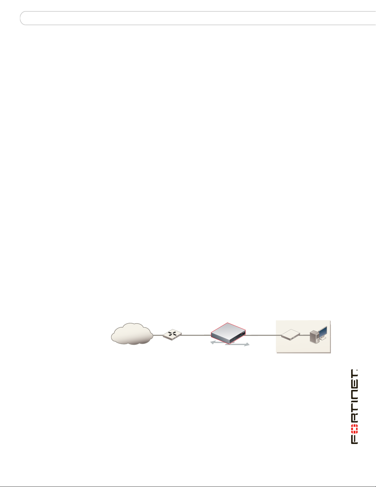
Figure 2: FortiGate unit in NAT mode
Internal network
Internet
Router
NAT mode policies controlling
traffic between internal
and external networks.
192.168.1.99204.23.1.5
192.168.1.20
You typically use NAT/Route mode when the FortiGate unit is operating as a
gateway between private and public networks. In this configuration, you would
create NAT mode firewall policies to control traffic flowing between the internal,
private network and the external, public network, usually the Internet.
FortiGate-60B FortiOS 3.0 MR6 Install Guide
01-30006-0446-20080910 15
Page 16
Connecting to the FortiGate unit Configuring
Transparent mode
In Transparent mode, the FortiGate unit is invisible to the network. Similar to a
network bridge, all FortiGate interfaces must be on the same subnet. You only
have to configure a management IP address to make configuration changes. The
management IP address is also used for antivirus and attack definition updates.
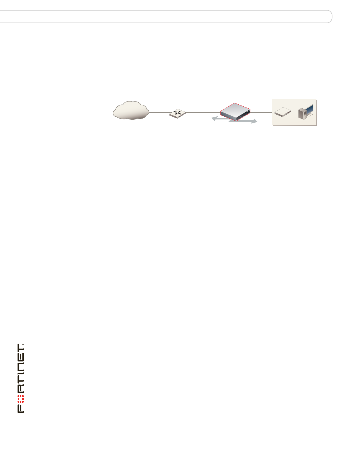
Figure 3: FortiGate unit in Transparent mode
10.10.10.1
Internet
Gateway to public network
204.23.1.2 10.10.10.2
External
Management IP
Internal
Internal Network
Router
You typically use the FortiGate unit in Transparent mode on a private network
behind an existing firewall or behind a router. The FortiGate unit performs firewall
functions, IPSec VPN, virus scanning, IPS web filtering, and Spam filtering.
Connecting to the FortiGate unit
To configure, maintain and administer the FortiGate unit, you need to connect to it.
There are two methods for these tasks:
• using the web-based manger, a GUI interface using a current web browser
such as FireFox or Internet Explorer.
• using the command line interface (CLI), a command line interface similar to
DOS or UNIX commands using an SSH terminal or Telnet terminal.
Connecting to the web-based manager
To connect to the web-based manager, you require:
• a computer with an Ethernet connection
• Microsoft Internet Explorer version 6.0 or higher or any recent version of the
most popular web browser
• an Ethernet cable.
Transparent mode policies
controlling traffic between
internal and external networks.
10.10.10.3
To connect to the web-based manager
1 Set the IP address of the management computer to the static IP address
192.168.1.2 with a netmask of 255.255.255.0.
2 Using the Ethernet cable, connect the internal interface of the FortiGate unit to the
computer Ethernet connection.
3 Start your browser and enter the address https://192.168.1.99. (remember to
include the “s” in https://).
FortiGate-60B FortiOS 3.0 MR6 Install Guide
16 01-30006-0446-20080910
Page 17

Configuring Connecting to the FortiGate unit
To support a secure HTTPS authentication method, the FortiGate unit ships with a
self-signed security certificate, which is offered to remote clients whenever they
initiate a HTTPS connection to the FortiGate unit. When you connect, the
FortiGate unit displays two security warnings in a browser.
The first warning prompts you to accept and optionally install the FortiGate unit’s
self-signed security certificate. If you do not accept the certificate, the FortiGate
unit refuses the connection. If you accept the certificate, the FortiGate login page
appears. The credentials entered are encrypted before they are sent to the
FortiGate unit. If you choose to accept the certificate permanently, the warning is
not displayed again.
Just before the FortiGate login page is displayed, a second warning informs you
that the FortiGate certificate distinguished name differs from the original request.
This warning occurs because the FortiGate unit redirects the connection. This is
an informational message. Select OK to continue logging in.
4 Type admin in the Name field and select Login.
Connecting to the CLI
To connect to the FortiGate CLI you require:
• a computer with an available communications port
• a serial cable, either a RJ-45 to DB-9 or null modem cable, whichever was
included in your FortiGate package
• terminal emulation software such as HyperTerminal for Microsoft Windows
Note: The following procedure uses Microsoft Windows HypterTerminal software. You can
apply these steps to any terminal emulation program.
To connect to the CLI
1 Connect the serial cable to the communications port of your computer and to the
FortiGate console port.
2 Start HyperTerminal, enter a name for the connection and select OK.
3 Configure HyperTerminal to connect directly to the communications port on your
computer and select OK.
4 Select the following port settings and select OK:
Bits per second 9600
Data bits 8
Parity None
Stop bits 1
Flow control None
5 Press Enter to connect to the FortiGate CLI.
6 When the login prompt appears, type admin and press Enter twice.
Type ? to list available commands. For information about how to use the CLI, see
the FortiGate CLI Reference.
FortiGate-60B FortiOS 3.0 MR6 Install Guide
01-30006-0446-20080910 17
Page 18

Configuring NAT mode Configuring
Configuring NAT mode
Configuring NAT mode involves defining interface addresses and default routes,
and simple firewall policies. You can use the web-based manager or the CLI to
configure the FortiGate unit in NAT/Route mode.
Using the web-based manager
After connecting to the web-based manager, you can use the following procedures
to complete the basic configuration of the FortiGate unit. Ensure you read the
section “Connecting to the web-based manager” on page 16 before beginning.
Configure the interfaces
When shipped, the FortiGate unit has a default address of 192.168.1.99 and a
netmask of 255.255.255.0. for either the Port 1 or Internal interface. You need to
configure this and other ports for use on your network.
To configure interfaces
1 Go to System > Network > Interface.
2 Select the edit icon for an interface.
3 Set the Addressing Mode for the interface.
• For Manual addressing, enter the IP address and netmask for the interface.
• For DHCP addressing, select DHCP and complete the following:
Distance Enter the administrative distance, between 1 and 255 for the
Retrieve default gateway
from server
Override internal DNS Enable to use the DNS addresses retrieved from the DHCP
default gateway retrieved from the DHCP server. The
administrative distance specifies the relative priority of a route
when there are multiple routes to the same destination. A
lower administrative distance indicates a more preferred route.
Enable to retrieve a default gateway IP address from the
DHCP server. The default gateway is added to the static
routing table.
server instead of the DNS server IP addresses on the DNS
page on System > Network > Options. On FortiGate-100
units and lower, you should also enable Obtain DNS server
address automatically in System > Network > Options.
• For PPPoE addressing, select PPPoE, and complete the following:
Username Enter the username for the PPPoE server. This may have
Password Enter the password for the PPPoE server for the above user
Unnumbered Specify the IP address for the interface. If your ISP has
Initial Disc Timeout Initial discovery timeout in seconds. The time to wait before
been provided by your ISP.
name.
assigned you a block of IP addresses, use one of these IP
addresses. Alternatively, you can use, or borrow, the IP
address of a configured interface on the router. You may need
to do this to minimize the number of unique IP addresses
within your network.
If you are borrowing an IP address remember the interface
must be enabled, or up to function correctly.
starting to retry a PPPoE discovery. To disable the discovery
timeout, set the value to 0.
FortiGate-60B FortiOS 3.0 MR6 Install Guide
18 01-30006-0446-20080910
Page 19

Configuring Configuring NAT mode
Initial PADT Timeout Initial PPPoE Active Discovery Terminate (PADT) timeout in
Distance Enter the administrative distance, between 1 and 255 for the
Retrieve default gateway
from server
Override internal DNS Enable to use the DNS addresses retrieved from the DHCP
seconds. Use this timeout to shut down the PPPoE session if it
is idle for this number of seconds. Your ISP must support
PADT. To disable the PADT timeout, set the value to 0.
default gateway retrieved from the DHCP server. The
administrative distance specifies the relative priority of a route
when there are multiple routes to the same destination. A
lower administrative distance indicates a more preferred route.
Enable to retrieve a default gateway IP address from the
DHCP server. The default gateway is added to the static
routing table.
server instead of the DNS server IP addresses on the DNS
page on System > Network > Options. On FortiGate-100
units and lower, you should also enable Obtain DNS server
address automatically in System > Network > Options.
4 Select OK.
5 Repeat this procedure for each interface as required.
Note: If you change the IP address of the interface you are connecting to, you must
connect through a web browser again using the new address. Browse to https:// followed by
the new IP address of the interface. If the new IP address of the interface is on a different
subnet, you may have to change the IP address of your computer to the same subnet.
Configure a DNS server
A DNS server is a service that converts symbolic node names to IP addresses. A
domain name server (DNS server) implements the protocol. In simple terms, it
acts as a phone book for the Internet. A DNS server matches domain names with
the computer IP address. This enables you to use readable locations, such as
fortinet.com when browsing the Internet.
DNS server IP addresses are typically provided by your internet service provider.
To configure DNS server settings
1 Go to System > Network > Options.
2 Enter the IP address of the primary DNS server.
3 Enter the IP address of the secondary DNS server.
4 Select Apply.
Adding a default route and gateway
A route provides the FortiGate unit with the information it needs to forward a
packet to a particular destination. A static route causes packets to be forwarded to
a destination other than the default gateway. You define static routes manually.
Static routes control traffic exiting the FortiGate unit-you can specify through
which interface the packet will leave and to which device the packet should be
routed.
In the factory default configuration, entry number 1 in the Static Route list is
associated with a destination address of 0.0.0.0/0.0.0.0, which means any/all
destinations. This route is called the "static default route". If no other routes are
present in the routing table and a packet needs to be forwarded beyond the
FortiGate unit, the factory configured static default route causes the FortiGate unit
to forward the packet to the default gateway.
FortiGate-60B FortiOS 3.0 MR6 Install Guide
01-30006-0446-20080910 19
Page 20

Configuring NAT mode Configuring
For an initial configuration, you must edit the factory configured static default route
to specify a different default gateway for the FortiGate unit. This will enable the
flow of data through the FortiGate unit.
For details on adding additional static routes, see the FortiGate Administration
Guide.
To modify the default gateway
1 Go to Router > Static.
2 Select Edit for the default route
3 In the Gateway field, type the IP address of the next-hop router where outbound
traffic is directed.
4 If the FortiGate unit reaches the next-hop router through a different interface
(compared to the interface that is currently selected in the Device field), select the
name of the interface from the Device field.
5 Select OK.
Adding firewall policies
Firewall policies enable traffic to flow through the FortiGate interfaces. Firewall
policies define how the FortiGate unit processes the packets in a communication
session. You can configure the firewall policies to allow only specific traffic, users
and specific times when traffic is allowed.
For the initial installation, a single firewall policy that enables all traffic through will
enable you to verify your configuration is working. On lower-end units such a
default firewall policy is already in place. For the higher end FortiGate units, you
will need to add a firewall policy.
The following steps add two policies that allows all traffic through the FortiGate
unit, to enable you to continue testing the configuration on the network.
To add an outgoing traffic firewall policy
1 Go to Firewall > Policy.
2 Select Create New.
3 Set the following and select OK.
Source Interface Select the port connected to the network.
Source Address All
Destination Interface Select the port connected to the Internet.
Destination Address All
Schedule always
Service Any
Action Accept
To add an incoming traffic firewall policy
1 Go to Firewall > Policy.
2 Select Create New.
FortiGate-60B FortiOS 3.0 MR6 Install Guide
20 01-30006-0446-20080910
Page 21

Configuring Configuring NAT mode
3 Set the following and select OK.
Source Interface Select the port connected to the Internet.
Source Address All
Destination Interface Select the port connected to the network.
Destination Address All
Schedule always
Service Any
Action Accept
Firewall policy configuration is the same in NAT/Route mode and Transparent
mode.
Note that these policies allow all traffic through. No protection profiles have been
applied. Ensure you create additional firewall policies to accommodate your
network requirements.
For details, see the FortiGate Administration Guide.
Using the CLI
After connecting to the CLI, you can use the following procedures to complete the
basic configuration of the FortiGate unit. Ensure you read the section “Connecting
to the CLI” on page 17 before beginning.
Configure the interfaces
When shipped, the FortiGate unit has a default address of 192.168.1.99 and a
netmask of 255.255.255.0. for either the Port 1 or Internal interface. You need to
configure this and other ports for use on your network.
To set an interface to use a static address
config system interface
edit <interface_name>
set mode static
set ip <address_ip> <netmask>
end
To set an interface to use DHCP addressing
config system interface
edit external
set mode dhcp
set distance <integer>
set defaultgw {enable | disable}
set dns-server-override {enable | disable}
end
FortiGate-60B FortiOS 3.0 MR6 Install Guide
01-30006-0446-20080910 21
Page 22

Configuring NAT mode Configuring
To set an interface to use PPPoE addressing
config system interface
edit external
set mode pppoe
set username <name_str>
set password <psswrd>
set ipunnumbered <ip_address>
set disc-retry-timeout <integer_seconds>
set padt-retry-timeout <integer_seconds>
set distance <integer>
set defaultgw {enable | disable}
set dns-server-override {enable | disable}
end
The CLI lists the IP address, netmask, and other settings for each of the FortiGate
interfaces.
Note: If you change the IP address of the interface you are connecting to, you must
connect through a web browser again using the new address. Browse to https:// followed by
the new IP address of the interface. If the new IP address of the interface is on a different
subnet, you may have to change the IP address of your computer to the same subnet.
Configure a DNS server
A DNS server is a service that converts symbolic node names to IP addresses. A
domain name server (DNS server) implements the protocol. In simple terms, it
acts as a phone book for the Internet. A DNS server matches domain names with
the computer IP address. This enables you to use readable locations, such as
fortinet.com when browsing the Internet.
DNS server IP addresses are typically provided by your internet service provider.
To configure DNS server settings
config system dns
set autosvr {enable | disable}
set primary <address_ip>
set secondary <address_ip>
end
Note if you set the autosvr to enable, you do not have to configure the primary
or secondary DNS server IP addresses.
Adding a default route and gateway
A route provides the FortiGate unit with the information it needs to forward a
packet to a particular destination. A static route causes packets to be forwarded to
a destination other than the default gateway. You define static routes manually.
Static routes control traffic exiting the FortiGate unit-you can specify through which
interface the packet will leave and to which device the packet should be routed.
In the factory default configuration, entry number 1 in the Static Route list is
associated with a destination address of 0.0.0.0/0.0.0.0, which means any/all
destinations. This route is called the "static default route". If no other routes are
present in the routing table and a packet needs to be forwarded beyond the
FortiGate unit, the factory configured static default route causes the FortiGate unit
to forward the packet to the default gateway.
FortiGate-60B FortiOS 3.0 MR6 Install Guide
22 01-30006-0446-20080910
Page 23

Configuring Configuring Transparent mode
For an initial configuration, you must edit the factory configured static default route
to specify a different default gateway for the FortiGate unit. This will enable the
flow of data through the FortiGate unit.
For details on adding additional static routes, see the FortiGate Administration
Guide.
To modify the default gateway
config router static
edit <seq_num>
set gateway <gateway_IP>
set device <interface>
end
Adding firewall policies
Firewall policies enable traffic to flow through the FortiGate interfaces. Firewall
policies to define the FortiGate unit process the packets in a communication
session. You can configure the firewall policies to allow only specific traffic, users
and specific times when traffic is allowed.
For the initial installation, a single firewall policy that enables all traffic through will
enable you to verify your configuration is working. On lower-end units such a
default firewall policy is already in place. For the higher end FortiGate units, you
will need to add a firewall policy.
The following steps add two policies that allows all traffic through the FortiGate
unit, to enable you to continue testing the configuration on the network.
To add an outgoing traffic firewall policy
config firewall profile
edit <seq_num>
set srcintf <source_interface>
set srcaddr <source_IP>
set dstintf <destination_interface>
set dstaddr <destination_IP>
set schedule always
set service ANY
set action accept
end
To create an incoming traffic firewall policy, use the same commands with the
addresses reversed.
Note that these policies allow all traffic through. No protection profiles have been
applied. Ensure you create additional firewall policies to accommodate your
network requirements.
Configuring Transparent mode
Configuring Transparent mode involves switching to Transparent mode,
configuring the management IP address, default routes, and simple firewall
policies. You can use the web-based manager or the CLI to configure the
FortiGate unit in Transparent mode.
FortiGate-60B FortiOS 3.0 MR6 Install Guide
01-30006-0446-20080910 23
Page 24

Configuring Transparent mode Configuring
Using the web-based manager
After connecting to the web-based manager, you can use the following
procedures to complete the basic configuration of the FortiGate unit. Ensure you
read the section “Connecting to the web-based manager” on page 16 before
beginning.
Switching to Transparent mode
The FortiGate unit comes preset to NAT mode. You need to switch to Transparent
mode.
To switch to Transparent mode
1 Go to System > Status.
2 Select Change beside the Operation Mode.
3 Select Transparent.
4 Enter the Management IP/Netmask address and the Default Gateway address.
The default gateway IP address is required to tell the FortiGate unit where to send
network traffic to other networks.
5 Select Apply.
Configure a DNS server
A DNS server is a service that converts symbolic node names to IP addresses. A
domain name server (DNS server) implements the protocol. In simple terms, it
acts as a phone book for the Internet. A DNS server matches domain names with
the computer IP address. This enables you to use readable locations, such as
fortinet.com when browsing the Internet.
DNS server IP addresses are typically provided by your internet service provider.
To configure DNS server settings
1 Go to System > Network > Options.
2 Enter the IP address of the primary DNS server.
3 Enter the IP address of the secondary DNS server.
Select Apply.
Adding firewall policies
Firewall policies enable traffic to flow through the FortiGate interfaces. Firewall
policies define the FortiGate unit process the packets in a communication session.
You can configure the firewall policies to allow only specific traffic, users and
specific times when traffic is allowed.
For the initial installation, a single firewall policy that enables all traffic through will
enable you to verify your configuration is working. On lower-end units such a
default firewall policy is already in place. For the higher end FortiGate units, you
will need to add a firewall policy.
The following steps add two policies that allows all traffic through the FortiGate
unit, to enable you to continue testing the configuration on the network.
FortiGate-60B FortiOS 3.0 MR6 Install Guide
24 01-30006-0446-20080910
Page 25

Configuring Configuring Transparent mode
To add an outgoing traffic firewall policy
1 Go to Firewall > Policy.
2 Select Create New.
3 Set the following and select OK.
Source Interface Select the port connected to the network.
Source Address All
Destination Interface Select the port connected to the Internet.
Destination Address All
Schedule always
Service Any
Action Accept
To add an incoming traffic firewall policy
1 Go to Firewall > Policy.
2 Select Create New.
3 Set the following and select OK.
Using the CLI
Source Interface Select the port connected to the Internet.
Source Address All
Destination Interface Select the port connected to the network.
Destination Address All
Schedule always
Service Any
Action Accept
Firewall policy configuration is the same in NAT/Route mode and Transparent
mode.
Note that these policies allow all traffic through. No protection profiles have been
applied. Ensure you create additional firewall policies to accommodate your
network requirements.
After connecting to the CLI, you can use the following procedures to complete the
basic configuration of the FortiGate unit. Ensure you read the section “Connecting
to the CLI” on page 17 before beginning.
Switching to Transparent mode
The FortiGate unit comes preset to NAT mode. You need to switch to Transparent
mode.
To switch to Transparent mode
config system settings
set opmode transparent
set manageip <address_ip> <netmask>
set gateway <address_gateway>
end
FortiGate-60B FortiOS 3.0 MR6 Install Guide
01-30006-0446-20080910 25
Page 26

Configuring Transparent mode Configuring
Configure a DNS server
A DNS server is a service that converts symbolic node names to IP addresses. A
domain name server (DNS server) implements the protocol. In simple terms, it
acts as a phone book for the Internet. A DNS server matches domain names with
the computer IP address. This enables you to use readable locations, such as
fortinet.com when browsing the Internet.
DNS server IP addresses are typically provided by your internet service provider.
To configure DNS server settings
config system dns
set autosvr {enable | disable}
set primary <address_ip>
set secondary <address_ip>
end
Note if you set the autosvr to enable, you do not have to configure the primary
or secondary DNS server IP addresses.
Adding firewall policies
Firewall policies enable traffic to flow through the FortiGate interfaces. Firewall
policies define the FortiGate unit process the packets in a communication session.
You can configure the firewall policies to allow only specific traffic, users and
specific times when traffic is allowed.
For the initial installation, a single firewall policy that enables all traffic through will
enable you to verify your configuration is working. On lower-end units such a
default firewall policy is already in place. For the higher end FortiGate units, you
will need to add a firewall policy.
The following steps add two policies that allows all traffic through the FortiGate
unit, to enable you to continue testing the configuration on the network.
To add an outgoing traffic firewall policy
config firewall profile
edit <seq_num>
set srcintf <source_interface>
set srcaddr <source_IP>
set dstintf <destination_interface>
set dstaddr <destination_IP>
set schedule always
set service ANY
set action accept
end
To create an incoming traffic firewall policy, use the same commands with the
addresses reversed.
Note that these policies allow all traffic through. No protection profiles have been
applied. Ensure you create additional firewall policies to accommodate your
network requirements.
FortiGate-60B FortiOS 3.0 MR6 Install Guide
26 01-30006-0446-20080910
Page 27

Configuring Verify the configuration
Verify the configuration
Your FortiGate unit is now configured and connected to the network. To verify the
FortiGate unit is connected and configured correctly, use your web browser to
browse a web site, or use your email client to send and receive email.
If you cannot browse to the web site or retrieve/send email from your account,
review the previous steps to ensure all information was entered correctly and try
again.
Remember, to verify the firewall policies. The firewall policies control the flow of
information through the FortiGate unit. If they are not set up correctly, or are too
restrictive, it can prohibit network traffic.
Backing up the configuration
Once you have determined your FortiGate is configured and working correctly, it is
extremely important that you back up your configuration. By backing up the
configuration, you ensure that if you need to reset the FortiGate unit for whatever
reason, you will be able to quickly return it to operation with minimal effort.
To back up the FortiGate configuration
1 Go to System > Maintenance > Backup & Restore.
2 Select to back up to your PC or to a USB key.
The USB Disk option will be grayed out if the FortiGate unit supports USB disks
but none are connected.
3 Select Encrypt the backup file.
Encryption must be enabled on the backup file to backup VPN certificates.
4 Enter a password and enter it again to confirm it. You will need this password to
restore the file.
5 Select Backup.
6 The web browser will prompt you for a location to save the configuration file. The
configuration file will have a .conf extension.
It is a good practice to backup the FortiGate configuration after any modification to
any of the FortiGate settings. Alternatively, before performing an upgrade to the
firmware, ensure you backup the configuration before upgrading. Should anything
happen during the upgrade that changes the configuration, you can easily restore
the saved configuration.
FortiGate-60B FortiOS 3.0 MR6 Install Guide
01-30006-0446-20080910 27
Page 28

Restoring a configuration Configuring
Restoring a configuration
Should you need to restore the configuration file, use the following steps.
To restore the FortiGate configuration
1 Go to System > Maintenance > Backup & Restore.
2 Select to upload the restore file from your PC or a USB key.
The USB Disk option will be grayed out if the FortiGate unit supports USB disks
but none are connected.
3 Enter the path and file name of the configuration file, or select Browse to locate
the file.
4 Enter a password if required.
5 Select Restore.
The FortiGate unit will load the configuration file and restart. Once the restart has
completed, verify that the configuration has been restored.
Additional configuration
With the FortiGate connected and allowing traffic to pass-through, there are a few
other configuration. While not mandatory, they will help in ensuring better control
with the firewall.
Set the time and date
For effective scheduling and logging, the FortiGate system date and time must be
accurate. You can either manually set the system date and time or configure the
FortiGate unit to automatically keep its time correct by synchronizing with a
Network Time Protocol (NTP) server.
To set the date and time
1 Go to System > Status.
2 Under System Information > System Time, select Change.
3 Select your Time Zone.
4 Optionally, select Automatically adjust clock for daylight saving changes.
5 Select Set Time and set the FortiGate system date and time.
6 If you want to synchronize the time with an NTP server, enable the option.
7 Select OK.
Note: If you choose the option Automatically adjust clock for daylight saving changes, the
system time must be manually adjusted after daylight savings time ends.
Set the Administrator password
The default administrator password is no password. You will want to apply a
password to prevent anybody logging into the FortiGate and changing
configuration options.
FortiGate-60B FortiOS 3.0 MR6 Install Guide
28 01-30006-0446-20080910
Page 29

Configuring Additional configuration
To change the administrator password
1 Go to System > Admin > Administrators.
2 Select Change Password and enter a new password.
3 Select OK.
Alternatively, you can also add new administrator users by selecting Create New,
however, you cannot remove the admin administrator. Applying a password for
this account is recommended.
Configure FortiGuard
Configure the FortiGate unit to connect to the FortiGuard Distribution Network
(FDN) to update the antivirus, antispam and IPS attack definitions.
The FDN is a world wide network of FortiGuard Distribution Servers (FDS). When
the FortiGate unit connects to the FDN, it connects to the nearest FDS. To do this,
all FortiGate units are programmed with a list of FDS addresses sorted by nearest
time zone according to the time zone configured for the FortiGate unit.
Before you can begin receiving updates, you must register your FortiGate unit
from the Fortinet web page. For information about registering your FortiGate unit,
see “Register your FortiGate unit” on page 7.
Updating antivirus and IPS signatures
After you have registered your FortiGate unit, you can update antivirus and IPS
signatures. The FortiGuard Center enables you to receive push updates, allow
push update to a specific IP address, and schedule updates for daily, weekly, or
hourly intervals.
To update antivirus definitions and IPS signatures
1 Go to System > Maintenance > FortiGuard.
2 Select the blue arrow for AntiVirus and IPS Options to expand the options.
3 Select Update Now to update the antivirus definitions.
If the connection to the FDN is successful, the web-based manager displays a
message similar to the following:
Your update request has been sent. Your database will
be updated in a few minutes. Please check your update
page for the status of the update.
After a few minutes, if an update is available, the System FortiGuard Center page
lists new version information for antivirus definitions. The System Status page also
displays new dates and version numbers for the antivirus definitions. Messages
are recorded to the event log indicating whether the update was successful or not.
Note: Updating antivirus definitions can cause a very short disruption in traffic currently
being scanned while the FortiGate unit applies the new signature database. Schedule
updates when traffic is light, for example overnight, to minimize any disruption.
For details on further FortiGuard configuration, see the FortiGate Administration
Guide.
FortiGate-60B FortiOS 3.0 MR6 Install Guide
01-30006-0446-20080910 29
Page 30

Additional configuration Configuring
FortiGate-60B FortiOS 3.0 MR6 Install Guide
30 01-30006-0446-20080910
Page 31

Advanced configuration Protection profiles
Advanced configuration
The FortiGate unit and the FortiOS operating system provide a wide range of
features that enable you to control network and internet traffic and protect your
network. This chapter describes some of these options and how to configure
them.
This chapter includes
• Protection profiles
• Firewall policies
• Antivirus options
• AntiSpam options
• Web filtering
• Logging
Protection profiles
A protection profile is a group of settings you can adjust to suit your requirements
for network protection. Since protection profiles apply different protection settings
to traffic controlled by firewall policies, you can tailor the settings to the type of
traffic each policy handles.
Use protection profiles to configure:
• antivirus protection
• web filtering
• web category filtering
• spam filtering
• content archiving
• instant messaging filtering and access control
• P2P access and bandwidth control
• logging options for policies and configurations within the policies
• rate limiting for VoIP protocols.
Using protection profiles, you can customize types and levels of protection for
different firewall policies.
For example, while traffic between internal and external addresses might need
strict protection, traffic between trusted internal addresses might need moderate
protection. You can configure policies for different traffic services to use the same
or different protection profiles.
The FortiGate unit is preconfigured with four default protection profiles. In many
cases you can use these default protection profiles, or use them as a starting
point in creating your own.
Table 1: Default protection profiles
Strict Applies maximum protection to HTTP, FTP, IMAP, POP3, and SMTP traffic.
Scan Apply virus scanning to HTTP, FTP, IMAP, POP3, and SMTP traffic.
FortiGate-60B FortiOS 3.0 MR6 Install Guide
01-30006-0446-20080910 31
The strict protection profile may not be useful under normal circumstances but
it is available when maximum protection is required.
Page 32

Firewall policies Advanced configuration
Web Apply virus scanning and web content blocking to HTTP traffic.
Unfiltered Apply no scanning, blocking or IPS. Use the unfiltered content profile if no
content protection for content traffic is required. Add this protection profile to
firewall policies for connections between highly trusted or highly secure
networks where content does not need to be protected.
The best way to begin creating your own protection profile is to open a predefined
profile. This way you can see how a profile is set up, and then modify it suit your
requirements. You access Protection profile options by going to Firewall >
Protection Profile, and selecting Edit for one of the predefined profiles.
Protection profiles are used by the firewall policies to determine how network and
Internet traffic is controlled, scanned and when necessary, rejected. The
Protection Profiles can be considered the rules of the firewall policy. Because of
this, you should take some time to review the various options to consider what you
want the firewall policies to do. If, after setting the protection profile and firewall
policies, traffic is not flowing or flowing too much, verify your profile settings.
The number of options and configuration for the protection profile is too vast for
this document. For details on each protection profile feature and setting, see the
FortiGate Administration Guide or the FortiGate Online Help.
Firewall policies
Firewall policies are instructions the FortiGate unit uses to decide what to do with
a connection request. When the firewall receives a connection request, it analyzes
it to extract its source address, destination address, and port number.
For the connection through the FortiGate unit to be successful, the source
address, destination address, and service of the connection must match a firewall
policy. The policy directs the firewall action for the connection. The action can be
to allow the connection, deny the connection, require authentication before the
connection is allowed, or process the packet as an IPSec VPN connection.
You can configure each firewall policy to route connections or apply network
address translation (NAT) to translate source and destination IP addresses and
ports. You also add protection profiles to firewall policies to apply different
protection settings for the traffic controlled by firewall policies.
The FortiGate unit matches firewall policies by searching from the top of the
firewall policy list and moving down until it finds the first match, then performs the
required address translation, blocking and so on described by the protection
profile, then passes on the packet information. This is important, because once
the FortiGate unit finds a match to a policy, it will not continue down the list. You
need to arrange policies in the policy list from more specific to more general.
For example, if you have two policies, one that blocks specific URLs or IP
addresses, and another general policy that lets traffic through. If you put the
general policy at the top, the FortiGate unit will act on the general policy, figuring
the policy has been matched and potentially let the URLs or IPs you wanted
blocked through.
Note: No traffic will flow through a FortiGate unit until at least one firewall policy is added.
FortiGate-60B FortiOS 3.0 MR6 Install Guide
32 01-30006-0446-20080910
Page 33

Advanced configuration Antivirus options
Configuring firewall policies
To add or edit a firewall policy go to Firewall > Policy and select Edit on an
existing policy, or select Create New to add a policy.
The source and destination Interface/Zone match the firewall policy with the
source and destination of a communication session. The Address Name matches
the source and destination address of the communication session.
Schedule defines when the firewall policy is enabled. While most policies are
always on, you can configure a firewall policy so that it is only on at specific times
of the day. For example, you may want to block news and entertainment sites
most of the day, except during lunch or after work, enabling your employees to
only view those sites during non-working times.
Service matches the firewall policy with the service used by a communication
session. This enables you to configure a policy for general web surfing and a
different policy specifically for other traffic such as SMTP mail or FTP uploads and
downloads.
Action defines how the FortiGate unit processes traffic. Specify an action to
accept or deny traffic or configure a firewall encryption policy.
• Add ACCEPT policies that accept communication sessions. Using an accept
policy, you can apply FortiGate features such as virus scanning and
authentication to the communication session accepted by the policy.
• Add DENY policies to deny communication sessions.
• Add IPSec encryption policies to enable IPSec tunnel mode VPN traffic and
SSL VPN encryption policies to enable SSL VPN traffic. Firewall encryption
policies determine which types of IP traffic will be permitted during an IPSec or
SSL VPN session.
Antivirus options
Select Protection Profile to include apply a protection profile to the firewall policy
for scanning of traffic passing through the FortiGate unit.
For details on the firewall policies features and settings, see the FortiGate
Administration Guide or the FortiGate Online Help.
The FortiGate unit’s antivirus configuration prevents malicious files from entering
and infecting your network environment.
The FortiGate unit uses a number of processes to scan files to ensure unwanted
files and potential attackers do not get through. The FortiGate unit scans using
these antivirus options:
• File pattern - The FortiGate will check the file against the file pattern setting
you have configured. You can set which file names or file types the FortiGate
unit looks for in the incoming traffic.
• Virus scan - The virus definitions are kept up to date through the FortiNet
Distribution Network. The list is updated on a regular basis so you do not have
to wait for a firmware upgrade. Note that you must register the FortiGate unit to
and purchase FortiGuard services to use virus scanning through the FDN.
FortiGate-60B FortiOS 3.0 MR6 Install Guide
01-30006-0446-20080910 33
Page 34

AntiSpam options Advanced configuration
• Grayware - These are unsolicited commercial software programs that are
installed on computers, often without the user's consent or knowledge.
Grayware programs are generally considered an annoyance, but these
programs can cause system performance problems or be used for malicious
ends. The FortiGate unit scans for known grayware executable programs in
each enabled category.
• Heuristics - The FortiGate heuristic antivirus engine performs tests on the file
to detect virus-like behavior or known virus indicators. In this way, heuristic
scanning may detect new viruses, but may also produce some false positive
results.
The antivirus elements work in sequence to give you an efficient method of
scanning incoming files. The first three elements have specific functions, the
fourth, the heuristics, is to cover any new previously unknown virus threats. The
four elements work together to offer your network unparalleled antivirus
protection. To ensure that your system is providing the most protection available,
all virus definitions and signatures are up dated regularly through the FortiGuard
antivirus services.
To configure the file patterns that the FortiGate scans, go to AntiVirus > File
Filter.
To enable grayware blocking, go to AntiVirus > Config > Grayware.
Antivirus settings are turned on in the protection profile. In the protection profile
you can enable antivirus options for specific services and which services will use
the file patterns as a part of the antivirus process.
To configure antivirus protection profile settings, go to Firewall > Protection
Profile. Select edit for a profile and select the Anti-Virus options.
For details on the antivirus features and settings, see the FortiGate Administration
Guide or the FortiGate Online Help.
AntiSpam options
The FortiGate unit’s antispam feature detects unsolicited commercial email by
identifying spam email messages and spam transmissions from known or
suspected spam servers.
This feature requires a FortiGuard subscription and a registered FortiGate unit.
When the FortiGate unit receives an email message, it verifies with the FortiGuard
server whether it is a valid email or a spam message. FortiGuard Antispam is one
of the features designed to manage spam. FortiGuard is an antispam system from
Fortinet that includes an IP address black list, a URL black list, and spam filtering
tools. The FortiGuard Center accepts submission of spam email messages as well
as well as reports of false positives.
Depending on how you configure the FortiGate unit, the FortiGate unit will either
tag the message with text so you can easily identify the spam, or delete the
message before it reaches the recipient.
The FortiGate unit also enables you to create your own spam filters using banned
words and black/white lists.
FortiGate-60B FortiOS 3.0 MR6 Install Guide
34 01-30006-0446-20080910
Page 35

Advanced configuration Web filtering
Banned word lists are specific words that may be typically found in email. The
FortiGate unit searches for words or patterns in email messages. If matches are
found, values assigned to the words are totalled. If the defined threshold value is
exceeded, the message is marked as spam. If no match is found, the email
message is passed along to the next filter.
You configure banned words by going to Antispam > Banned Word.
While FortiGuard services maintain a large list of known spammers, it is not
perfect. In some cases, some mail tagged as spam is an individual you want to
receive mail from, while email that is not caught by the spam filters or users you
don’t want to receive email from gets through to your inbox.
White lists and black lists enable you to maintain a list of email addresses that you
want (white list) or don’t want (black list) to receive email from. You can add or
remove addresses from lists as required. The FortiGate unit uses both an IP
address list and an email address list to filter incoming email, if enabled in the
protection profile.
When performing an IP address list check, the FortiGate unit compares the IP
address of the message's sender to the IP address list in sequence. If a match is
found, the action associated with the IP address is taken. If no match is found, the
message is passed to the next enabled spam filter.
Web filtering
When performing an email list check, the FortiGate unit compares the email
address of the message's sender to the email address list in sequence. If a match
is found, the action associated with the email address is taken. If no match is
found, the message is passed to the next enabled antispam filter.
To configure black/white lists, go to AntiSpam > Black/White List.
You enable antispam options for each mail service (POP3, IMAP and SMTP) in
the protection profile. To configure antispam protection profile settings, go to
Firewall > Protection Profile. Select edit for a profile and select the Spam
Filtering options.
For details on the antispam features and settings, see the FortiGate
Administration Guide or the FortiGate Online Help.
Web filtering is a method of controlling what web sites are viewable by users.
There are three main sections to web filtering: the Web Filter Content Block, the
URL Filter, and the FortiGuard Web filter. Each interact with each other in such a
way as to provide maximum control and protection for the Internet users.
Web filtering options are enabled and configured in the protection profile settings
by going to Firewall > Protection Profile. Select edit for a profile and selecting
either the FortiGuard Web Filtering options or the Web Filtering options. You need
to register your FortiGate unit and purchase FortiGuard services to use
FortiGuard Web Filtering.
Content blocking enables you to specify file types and words that the FortiGate
unit should block when encountered. With web content block enabled, every
requested web page is checked against the content block list. The score value of
each pattern appearing on the page is added, and if the total is greater than the
threshold value set in the protection profile, the page is blocked.
FortiGate-60B FortiOS 3.0 MR6 Install Guide
01-30006-0446-20080910 35
Page 36

Logging Advanced configuration
To configure content blocking, go to Web Filter > Content Block.
URL filter enables you to control additional web sites that you can block or allow.
This enables you greater control over certain URLs or sub-URLs. The FortiGate
unit allows or blocks web pages matching any specified URLs or patterns and
displays a replacement message instead.
To configure URL filters, go to Web Filter > URL Filter.
FortiGuard web filtering is a managed web filtering solution provided by Fortinet.
FortiGuard web filtering sorts hundreds of millions of web pages into a wide range
of categories users can allow, block, or monitor. FortiGuard web filtering includes
over 60 million individual ratings of web sites applying to hundreds of millions of
pages. Pages are sorted and rated into 56 categories users can allow, block, or
monitor. Categories may be added to, or updated, as the Internet evolves. You
need to have a FortiGuard subscription to take advantage of FortiGuard web
filtering.
The FortiGate unit also enables you to override the FortiGuard filtering
designation, and you can add your own. To customize your FortiGuard web
filtering, go to Web Filter > FortiGuard - Web Filter.
For details and configuration options for the web filtering features and settings,
see the FortiGate Administration Guide or the FortiGate Online Help.
Logging
Logging is an indirect method of protecting your network. The FortiGate unit’s
robust logging features enable you to see the attacks, spam and virus activity is
occurring on your network. Using this information, you can then take the corrective
action necessary to resolve any problems before they become major problems.
With alert email, you can configure the FortiGate unit to send alert messages,
when specific events occur with specific frequency. By logging to a FortiAnalyzer
unit, you can run over 300 reports on various network traffic.
To configure logging, go to Log&Report > Log Setting.
For details and configuration options for the logging features and settings, see the
FortiGate Administration Guide or the FortiGate Online Help.
FortiGate-60B FortiOS 3.0 MR6 Install Guide
36 01-30006-0446-20080910
Page 37

Configuring the modem interface Selecting a modem mode
Configuring the modem interface
This chapter describes the modem interface configuration options. The FortiGate
unit supports the modem interface only when running in NAT/Route mode.
You can configure the modem interface for stand alone mode, the direct
connection to the Internet, or for redundant mode, to act as a backup connection
to the Internet, should the primary connection fail.
This chapter includes the following topics:
• Selecting a modem mode
• Configuring modem settings
• Configuring the modem using the CLI
• Adding a Ping Server
• Adding firewall policies for modem connections
• Administrative access through the modem port
• Configuring the PCMCIA modem card
Selecting a modem mode
The modem interface can work in one of two modes: redundant and stand alone
mode.
To select an operational mode for the modem interface
1 Go to System > Network > Modem.
2 Select Enable modem.
3 Select Redundant for the mode.
To select an operational mode using the CLI, type:
config system modem
set status enable
set status mode redundant
end
Redundant mode
The redundant modem interface is a backup to the external interface connected to
the Internet. If the Ethernet connection goes down for whatever reason, the
modem automatically dials the configured dial-up account(s). When the modem
connects to a dial-up account, the FortiGate unit routes IP packets normally
destined for the selected Ethernet interface to the modem interface. During this
time, the FortiGate unit pings the Ethernet connection to check when it is back
online.
FortiGate-60B FortiOS 3.0 MR6 Install Guide
01-30006-0446-20080910 37
Page 38
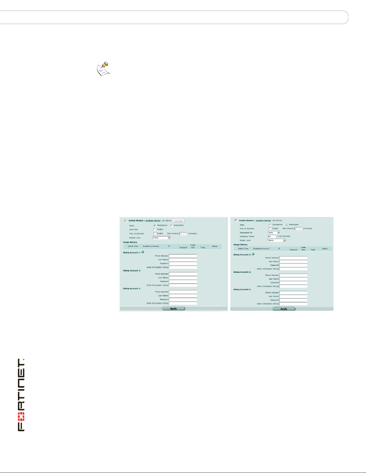
Configuring modem settings Configuring the modem interface
When the Ethernet interface can connect to its network again, the FortiGate unit
disconnects the modem interface and switches back to the Ethernet interface.
Note: Do not add firewall policies for connections between the Ethernet interface that the
modem replaces and other interfaces.
Note: Do not add a default route to the Ethernet interface that the modem interface
replaces.
Stand alone mode
In stand alone mode, the modem interface operates as the primary connection to
the Internet. The FortiGate unit routes traffic through the modem interface, which
remains permanently connected to the dial-up account.
If the connection to the dial-up account fails, the FortiGate unit modem
automatically redials the number. The modem redials the ISP number based on
the amount of times specified by the redial limit, or until it connects to a dial-up
account.
Configuring modem settings
To configure the modem settings, go to System > Network > Modem.
Figure 4: Modem settings (Stand alone and Redundant)
Enable Modem Select to enable the FortiGate modem.
Modem status The modem status shows one of the following: “not active”,
Dial Now/Hang Up (Stand alone mode only) Select Dial Now to manually connect to a
Mode Select Stand alone or Redundant mode. In Stand alone mode, the
Auto-dial (Stand alone mode only) Select to dial the modem automatically if
Redundant for (Redundant mode only) Select the Ethernet interface the modem
“connecting”, “connected”, “disconnecting” or “hung up” (Stand
alone mode only).
dial-up account. If the modem is connected, you can select Hang
Up to manually disconnect the modem.
modem is an independent interface. In Redundant mode, the
modem is a backup facility for a selected Ethernet interface.
the connection is lost or the FortiGate unit is restarted. You cannot
select Auto-dial if Dial on demand is selected.
provides backup service.
FortiGate-60B FortiOS 3.0 MR6 Install Guide
38 01-30006-0446-20080910
Page 39

Configuring the modem interface Configuring modem settings
Dial on demand Select to dial the modem when packets are routed to the modem
Idle timeout (Stand alone mode only) Enter the timeout duration in minutes.
Holddown
Timer
Redial Limit The maximum number of times (1-10) the FortiGate unit modem
PCMCIA Wireless
Modem
Usage History Displays the traffic and uptime of the modem interface.
Dialup Account Configure up to three dial-up accounts. The FortiGate unit tries
Device Select the modem type for the dialup account.
Phone Number The phone number required to connect to the dialup account. Do
User Name The user name (maximum 63 characters) sent to the ISP.
Password The password sent to the ISP.
Extra Initilization
String
interface. The modem disconnects after the idle timeout period if
there is no network activity. When traffic occurs on the interface, the
FortiGate unit dials the modem again.
In Standalone mode, you cannot select Dial on demand if Auto-dial
is selected.
After this period of inactivity, the modem disconnects.
(Redundant mode only) Enter the time (1-60 seconds) the FortiGate
unit waits before switching from the modem interface to the primary
interface, after the primary interface has been restored. Configure a
higher value if you find the FortiGate unit switching repeatedly
between the primary interface and the modem interface.
attempts to reconnect to the ISP if the connection fails. Select None
to have no limit on redial attempts.
Displays the status of a wireless modem card installed in a
FortiGate-60B, if available. Select the Supported Modems link to
view the list of wireless modems tested by Fortinet.
connecting to each account in order until a connection can be
established.
not add spaces to the phone number. Make sure to include
standard special characters for pauses, country codes, and other
functions as required by your modem to connect to your dialup
account.
Include additional initialization strings that may be required for a
proper connection.
You can configure and use the modem in NAT/Route mode only.
To configure modem settings
1 Go to System > Network > Modem.
2 Select Enable Modem.
3 Change any of the dial-up connection settings.
4 Enter the settings for Dial-up Account 1 settings.
5 If you have multiple dial-up accounts, enter Phone Number, User Name, and
Password for Dial-up Account 2 and Dial-up Account 3.
6 Select Apply.
FortiGate-60B FortiOS 3.0 MR6 Install Guide
01-30006-0446-20080910 39
Page 40

Configuring the modem using the CLI Configuring the modem interface
Configuring the modem using the CLI
Configure the modem settings using the CLI.
Syntax
config system modem
set account_relation {equal | fallback}
set altmode {enable | disable}
set auto-dial {enable | disable}
set connect-timeout <seconds>
set dial-on-demand {enable | disable}
set distance <distance>
set extra-init1 <string>
set extra-init2 <string>
set extra-init3 <string>
set holddown-timer <seconds>
set idle-timer <minutes>
set interface <name>
set mode {redudant | standalone}
set modem-dev1{internal | pcmica-wireless}
set modem-dev2{internal | pcmica-wireless}
set modem-dev3{internal | pcmica-wireless}
set passwd1 <password_str>
set passwd2 <password_str>
set passwd3 <password_str>
set peer-modem1 {actiontec | ascendTNT | generic}
set peer-modem2 {actiontec | ascendTNT | generic}
set peer-modem3 {actiontec | ascendTNT | generic}
set phone1 <phone-number>
set phone2 <phone-number>
set phone3 <phone-number>
set pin-init <string>
set priority <integer>
set redial <tries_integer>
set status {disable | enable}
set username1 <name_str>
set username2 <name_str>
set username3 <name_str>
set wireless-custom-vendor-id <hex_string>
set wireless-custom-product-id <hex_string>
end
FortiGate-60B FortiOS 3.0 MR6 Install Guide
40 01-30006-0446-20080910
Page 41

Configuring the modem interface Configuring the modem using the CLI
Keywords and variables Description Default
account_relation {equal |
fallback}
When using a PCMCIA wireless
modem, set the relationship between
the wireless modem and the internal
modem.
equal - both accounts are equal.
When the FortiGate unit attempts to
connect, it tries both modems, and the
first one to connect becomes the
primary account connection.
fallback - the first account in the list
is the primary connection account. The
second account is a redundant account
that takes over when the primary
account drops its connection or fails.
As soon as the primary connection is
restored, the secondary connection
disconnects.
equal
altmode {enable | disable} Enable for installations using PPP in
auto-dial
{enable | disable}
connect-timeout <seconds> Set the connection completion timeout
dial-on-demand
{enable | disable}
distance <distance> Enter the administrative distance (1-
extra-init1 <string> Enter additional initialization strings
extra-init2 <string> Enter additional initialization strings
extra-init3 <string> Enter additional initialization strings
China.
Enable to dial the modem automatically
if the connection is lost or the FortiGate
unit is restarted.
This is available only when
dial-on-demand is set to disabled,
and mode is set to standalone.
(30 - 255 seconds).
Enable to dial the modem when
packets are routed to the modem
interface. The modem disconnects
after the idle-timer period.
This is available only if
auto-dial is set to disabled, and
mode is set to standalone.
255) to use for the default route that is
automatically added when the modem
connects and obtains an IP address. A
lower distance indicates a more
preferred route.
This keyword is useful for configuring
redundant routes in which the modem
interface acts as a backup to another
interface.
that may be required for a proper
connection.
that may be required for a proper
connection.
that may be required for a proper
connection.
enable
disable
90
disable
1
No default.
No default.
No default.
FortiGate-60B FortiOS 3.0 MR6 Install Guide
01-30006-0446-20080910 41
Page 42

Configuring the modem using the CLI Configuring the modem interface
Keywords and variables Description Default
holddown-timer <seconds> Used only when the modem is
idle-timer <minutes> Set the number of minutes the modem
interface <name> Enter an interface name to associate
mode {redudant |
standalone}
modem-dev1{internal |
pcmica-wireless}
modem-dev2{internal |
pcmica-wireless}
modem-dev3{internal |
pcmica-wireless}
passwd1 <password_str> Enter the password used to access the
passwd2 <password_str> Enter the password used to access the
passwd3 <password_str> Enter the password used to access the
peer-modem1
{actiontec | ascendTNT
| generic}
peer-modem2
{actiontec | ascendTNT
| generic}
peer-modem3
{actiontec | ascendTNT
| generic}
configured as a backup for an
interface. Set the time (1-60 seconds)
that the FortiGate unit waits before
switching from the modem interface to
the primary interface, after the primary
interface has been restored.
This is available only when mode is set
to redundant.
connection can be idle before it is
disconnected.
This is available only if mode is set to
standalone.
the modem interface with the ethernet
interface that you want to either back
up (backup configuration) or replace
(standalone configuration).
Enter the required mode:
• redundant
The modem interface automatically
takes over from a selected ethernet
interface when that ethernet interface
is unavailable.
• standalone
The modem interface is the connection
from the FortiGate unit to the Internet.
Set the modem type for the selected
dialup account.
Set the modem type for the selected
dialup account.
Set the modem type for the selected
dialup account.
specified dialup account.
specified dialup account.
specified dialup account.
If the modem at phone1 is Actiontec or
AscendTNT, select that type, otherwise
leave setting as generic.
This setting applies to models 50AM,
60M and WiFi-60M only.
If the modem at phone2 is Actiontec or
AscendTNT, select that type, otherwise
leave setting as generic.
This setting applies to models 50AM,
60M and WiFi-60M only.
If the modem at phone3 is Actiontec or
AscendTNT, select that type, otherwise
leave setting as generic.
This setting applies to models 50AM,
60M and WiFi-60M only.
60
5
No default.
standalone
internal
internal
internal
No default.
No default.
No default.
generic
generic
generic
FortiGate-60B FortiOS 3.0 MR6 Install Guide
42 01-30006-0446-20080910
Page 43

Configuring the modem interface Configuring the modem using the CLI
Keywords and variables Description Default
phone1
<phone-number>
phone2 <phone-number> Enter the phone number required to
phone3 <phone-number> Enter the phone number required to
pin-init <string> Enter additional pin initialization strings
priority <integer> Enter the priority of learned routes on
redial <tries_integer> Set the maximum number of times (1-
status
{disable | enable}
username1 <name_str> Enter the user name used to access
username2 <name_str> Enter the user name used to access
username3 <name_str> Enter the user name used to access
wireless-custom-vendor-id
<hex_string>
wireless-custom-product-id
<hex_string>
Enter the phone number required to
connect to the dialup account. Do not
add spaces to the phone number.
Make sure to include standard special
characters for pauses, country codes,
and other functions as required by your
modem to connect to your dialup
account.
connect to the dialup account. Do not
add spaces to the phone number.
Make sure to include standard special
characters for pauses, country codes,
and other functions as required by your
modem to connect to your dialup
account.
connect to the dialup account. Do not
add spaces to the phone number.
Make sure to include standard special
characters for pauses, country codes,
and other functions as required by your
modem to connect to your dialup
account.
that may be required for a proper
connection.
this interface.
Valid priorities are from 0 to
4294967295.
10) that the FortiGate unit dials the ISP
to restore an active connection on the
modem interface. Select none to allow
the modem to redial without a limit.
Enable or disable modem support. This
is equivalent to bringing an interface up
or down.
the specified dialup account.
the specified dialup account.
the specified dialup account.
Enter the wireless modem vendor ID
as a hexadecimal number.
Enter the wireless modem product ID
as a hexadecimal number.
No default.
No default.
No default.
No default
0
No default.
disable
No default.
No default.
No default.
No default
No default
Example
This example shows how to enable the modem and configure the modem to act
as a backup for the WAN1 interface. Only one dial-up account is configured. The
FortiGate unit and modem will attempt to dial this account 10 times. The FortiGate
unit will wait 5 seconds after the WAN1 interface recovers before switching back
to the WAN1 interface.
FortiGate-60B FortiOS 3.0 MR6 Install Guide
01-30006-0446-20080910 43
Page 44

Adding a Ping Server Configuring the modem interface
config system modem
set action dial
set status enable
set holddown-timer 5
set interface wan1
set passwd1 acct1passwd
set phone1 1234567891
set redial 10
set username1 acct1user
end
Adding a Ping Server
Adding a ping server is required for routing failover for the modem in redundant
mode. A ping server confirms the connectivity to an Ethernet interface. When the
Ethernet connection to the Internet goes down, the ping server will continually
check the interface until it comes up. When it does come up, the FortiGate unit will
switch back to the Ethernet connection and shut down the modem.
To add a ping server to an interface
1 Go to System > Network > Interface.
2 Choose an interface and select Edit.
3 Set Ping Server to the IP address of the next hop router on the network connected
to the interface.
4 Select the Enable check box.
5 Select OK to save the changes.
Dead gateway detection
The FortiGate unit uses dead gateway detection to ping the Ping Server IP
address to make sure the FortiGate unit can connect to this IP address.
Modify dead gateway detection to control how the FortiGate unit confirms
connectivity with a ping server added to an interface configuration. For information
about adding a ping server to an interface, see above.
To modify the dead gateway detection settings
1 Go to System > Network > Options.
2 For Detection Interval, type a number in seconds to specify how often the
FortiGate unit tests the connection to the ping target.
3 For Fail-over Detection, type a number of times that the connection test fails
before the FortiGate unit assumes the gateway is no longer functioning.
4 Select Apply.
FortiGate-60B FortiOS 3.0 MR6 Install Guide
44 01-30006-0446-20080910
Page 45

Configuring the modem interface Adding firewall policies for modem connections
Adding firewall policies for modem connections
The modem interface requires firewall addresses and policies. You can add one
or more addresses to the modem interface. For information about adding
addresses, see the FortiGate Administration Guide. When you add addresses, the
modem interface appears on the policy grid.
You can configure firewall policies to control the flow of packets between the
modem interface and the other interfaces on the FortiGate unit. For information
about adding firewall policies, see the FortiGate Administration Guide.
Administrative access through the modem port
In a configuration where the FortiGate unit is assigned a dynamic IP address from
the ISP, you can use the modem connection as a method of gaining administrative
access to the FortiGate unit.
You can enable login from modem connection using the standard connection
options available to the other FortiGate ports; telnet, ssh, http, https and ping
To enable administrative access on the modem interface
1 Go to System > Interface.
2 Select edit for the Modem interface.
3 Select the access options and select OK.
Configuring the PCMCIA modem card
PCMCIA/PC Card 3G wireless access is configured using the web-based
manager.
Most ISPs require that the modem card be activated with their network before
using it. You must activate it before installing it in FortiGate unit. Consult your ISP
for instructions on how to activate the modem card.
Ensure the FortiGate unit is powered off before installing the modem card. Once
installed, you can power on the FortiGate unit.
To configure the modem
1 Go to System > Network > Modem.
2 Select Enable modem.
3 Configure the modem settings as required.
4 In the configuration section, for the Dialup Account 1, enter the account details
provided to you by your 3G access provider.
5 Fort the Device, select PCMCIA wireless modem.
6 Enter the telephone number.
This can vary depending on the provider. The most common is *99#. Verify this
with your cellular provider.
FortiGate-60B FortiOS 3.0 MR6 Install Guide
01-30006-0446-20080910 45
Page 46

Configuring the PCMCIA modem card Configuring the modem interface
7 If a security pin is required, enter in the Extra Initialization String field in the
following format:
at+cpin=5555
where 5555 is the pin provided to you by your ISP.
8 Select Apply.
Create a static route, firewall policies and VPN configuration using this modem
interface, just as you would any physical interface.
FortiGate-60B FortiOS 3.0 MR6 Install Guide
46 01-30006-0446-20080910
Page 47

FortiGate Firmware Downloading firmware
FortiGate Firmware
Fortinet periodically updates the FortiGate firmware to include new features and
address issues. After you have registered your FortiGate unit, you can download
FortiGate firmware updates is available for download at the support web site,
http://support.fortinet.com.
You can also use the instructions in this chapter to downgrade, or revert, to a
previous version. The FortiGate unit includes a number of firmware installation
options that enables you to test new firmware without disrupting the existing
installation, and load it from different locations as required.
In addition to firmware images, Fortinet issues patch releases--maintenance
release builds that resolve important issues. Fortinet strongly recommends
reviewing the release notes for the patch release, as well as testing and reviewing
the patch release before upgrading the firmware. Follow the steps below:
• download and review the release notes for the patch release
• download the patch release
• back up the current configuration
• install the patch release using the procedure “Testing new firmware before
installing” on page 56
• test the patch release until you are satisfied that it applies to your
configuration.
Installing a patch release without reviewing release notes or testing the firmware
may result in changes to settings or unexpected issues.
Only FortiGate admin user and administrators whose access profiles contain
system read and write privileges can change the FortiGate firmware.
This section includes the following topics:
• Downloading firmware
• Using the web-based manager
• Using the CLI
• Installing firmware from a system reboot using the CLI
• Testing new firmware before installing
Downloading firmware
Firmware images for all FortiGate units is available on the Fortinet Customer
Support web site. You must register your FortiGate unit to access firmware
images. Register the FortiGate unit by visiting http://support.fortinet.com and
select Product Registration.
FortiGate-60B FortiOS 3.0 MR6 Install Guide
01-30006-0446-20080910 47
Page 48

Using the web-based manager FortiGate Firmware
To download firmware
1 Log into the site using your user name and password.
2 Go to Firmware Images > FortiGate.
3 Select the most recent FortiOS version, and MR release and patch release.
4 Locate the firmware for your FortiGate unit, right-click the link and select the
Download option for your browser.
Note: Always review the Release Notes for a new firmware release before installing. The
Release Notes can include information that is not available in the regular documentation.
Using the web-based manager
Upgrading the firmware
Installing firmware replaces your current antivirus and attack definitions, along
with the definitions included with the firmware release you are installing. After you
install new firmware, make sure that antivirus and attack definitions are up to date.
For details, see the FortiGate Administration Guide.
To upgrade the firmware
1 Download the firmware image file to your management computer.
2 Log into the web-based manager as the admin administrative user.
3 Go to System > Status.
4 Under System Information > Firmware Version, select Update.
5 Type the path and filename of the firmware image file, or select Browse and locate
the file.
6 Select OK.
The FortiGate unit uploads the firmware image file, upgrades to the new firmware
version, restarts, and displays the FortiGate login. This process takes a few
minutes.
Reverting to a previous version
The following procedures revert the FortiGate unit to its factory default
configuration and deletes IPS custom signatures, web content lists, email filtering
lists, and changes to replacement messages.
Before beginning this procedures, it is recommended that you back up the
FortiGate unit configuration.
If you are reverting to a previous FortiOS version, you might not be able to restore
the previous configuration from the backup configuration file.
Note: Installing firmware replaces the current antivirus and attack definitions, along with the
definitions included with the firmware release you are installing. After you install new
firmware, make sure that antivirus and attack definitions are up to date. For details, see the
FortiGate Administration Guide.
FortiGate-60B FortiOS 3.0 MR6 Install Guide
48 01-30006-0446-20080910
Page 49

FortiGate Firmware Using the web-based manager
Note: To use this procedure, you must log in using the admin administrator account, or an
administrator account that has system configuration read and write privileges.
To revert to a previous firmware version
1 Copy the firmware image file to the management computer.
2 Log into the FortiGate web-based manager.
3 Go to System > Status.
4 Under System Information > Firmware Version, select Update.
5 Type the path and filename of the firmware image file, or select Browse and locate
the file.
6 Select OK.
The FortiGate unit uploads the firmware image file, reverts to the old firmware
version, resets the configuration, restarts, and displays the FortiGate login. This
process takes a few minutes.
7 Log into the web-based manager.
8 Restore your configuration.
For information about restoring your configuration see “Restoring a configuration”
on page 28.
Backup and Restore from a USB key
Use a USB key to either backup a configuration file or restore a configuration file.
You should always make sure a USB key is properly install before proceeding
since the FortiGate unit must recognize that the key is installed in its USB port.
Note: You can only save VPN certificates if you encrypt the file. Make sure the
configuration encryption is enabled so you can save the VPN certificates with the
configuration file. An encrypted file is ineffective if selected for the USB Auto-Install feature.
To backup configuration
1 Go to System > Maintenance > Backup and Restore.
2 Select USB Disk from the backup configuration to list.
3 Enter a file name for the configuration file.
4 Select Backup.
To restore configuration
1 Go to System > Maintenance > Backup and Restore.
2 Select USB Disk from the restore configuration from list.
3 Select a backup configuration file from the list.
4 Select Restore.
Using the USB Auto-Install
The USB Auto-Install feature automatically updates the FortiGate configuration
file and image file on a system reboot. Also, this feature provides you with an
additional backup if you are unable to save your system settings before shutting
down or rebooting your FortiGate unit.
FortiGate-60B FortiOS 3.0 MR6 Install Guide
01-30006-0446-20080910 49
Page 50

Using the CLI FortiGate Firmware
Note: You need an unencrypted configuration file for this feature. Also the default files,
image.out and system.conf, must be in the root directory of the USB key.
Note: Make sure at least FortiOS v3.0MR1 is installed on the FortiGate unit before
installing.
To configure the USB Auto-Install
1 Go to System > Maintenance > Backup and Restore.
2 Select the blue arrow to expand the Advanced options.
3 Select the following:
• On system restart, automatically update FortiGate configuration file if default
file name is available on the USB disk.
• On system restart, automatically update FortiGate firmware image if default
image is available on the USB disk.
4 Enter the configuration and image file names or use the default configuration
filename (system.conf) and default image name (image.out).
5 The default configuration filename should show in the Default configuration file
name field.
Using the CLI
6 Select Apply.
Installing firmware replaces your current antivirus and attack definitions, along
with the definitions included with the firmware release you are installing. After you
install new firmware, make sure that antivirus and attack definitions are up to date.
You can also use the CLI command execute update-now to update the
antivirus and attack definitions. For details, see the FortiGate Administration
Guide.
Before you begin, ensure you have a TFTP server running and accessible to the
FortiGate unit.
To upgrade the firmware using the CLI
1 Make sure the TFTP server is running.
2 Copy the new firmware image file to the root directory of the TFTP server.
3 Log into the CLI.
4 Make sure the FortiGate unit can connect to the TFTP server.
You can use the following command to ping the computer running the TFTP
server. For example, if the IP address of the TFTP server is 192.168.1.168:
execute ping 192.168.1.168
FortiGate-60B FortiOS 3.0 MR6 Install Guide
50 01-30006-0446-20080910
Page 51

FortiGate Firmware Using the CLI
5 Enter the following command to copy the firmware image from the TFTP server to
the FortiGate unit:
execute restore image <name_str> <tftp_ip4>
Where <name_str> is the name of the firmware image file and <tftp_ip4> is
the IP address of the TFTP server. For example, if the firmware image file name is
image.out and the IP address of the TFTP server is 192.168.1.168, enter:
execute restore image image.out 192.168.1.168
The FortiGate unit responds with the message:
This operation will replace the current firmware version!
Do you want to continue? (y/n)
6 Type y.
The FortiGate unit uploads the firmware image file, upgrades to the new firmware
version, and restarts. This process takes a few minutes.
7 Reconnect to the CLI.
8 Update antivirus and attack definitions, by entering:
execute update-now
Reverting to a previous version
This procedure reverts the FortiGate unit to its factory default configuration and
deletes IPS custom signatures, web content lists, email filtering lists, and changes
to replacement messages.
Before beginning this procedure, it is recommended that you:
• back up the FortiGate unit system configuration using the command
execute backup config
• back up the IPS custom signatures using the command execute
backup ipsuserdefsig
• back up web content and email filtering lists
If you are reverting to a previous FortiOS version (for example, reverting from
FortiOS v3.0 to FortiOS v2.80), you might not be able to restore the previous
configuration from the backup configuration file.
Note: Installing firmware replaces your current antivirus and attack definitions, along with
the definitions included with the firmware release you are installing. After you install new
firmware, make sure that antivirus and attack definitions are up to date. You can also use
the CLI command execute update-now to update the antivirus and attack definitions.
Note: To use this procedure, you must log in using the admin administrator account, or an
administrator account that has system configuration read and write privileges.
To use the following procedure, you must have a TFTP server the FortiGate unit
can connect to.
To revert to a previous firmware version using the CLI
1 Make sure the TFTP server is running
2 Copy the firmware image file to the root directory of the TFTP server.
3 Log into the FortiGate CLI.
FortiGate-60B FortiOS 3.0 MR6 Install Guide
01-30006-0446-20080910 51
Page 52

Installing firmware from a system reboot using the CLI FortiGate Firmware
4 Make sure the FortiGate unit can connect to the TFTP server.
You can use the following command to ping the computer running the TFTP
server. For example, if the TFTP server’s IP address is 192.168.1.168:
execute ping 192.168.1.168
5 Enter the following command to copy the firmware image from the TFTP server to
the FortiGate unit:
execute restore image <name_str> <tftp_ipv4>
Where <name_str> is the name of the firmware image file and <tftp_ip4> is
the IP address of the TFTP server. For example, if the firmware image file name is
imagev28.out and the IP address of the TFTP server is 192.168.1.168, enter:
execute restore image image28.out 192.168.1.168
The ForitGate unit responds with this message:
This operation will replace the current firmware version!
Do you want to continue? (y/n)
6 Type y.
The FortiGate unit uploads the firmware image file. After the file uploads, a
message similar to the following appears:
Get image from tftp server OK.
Check image OK.
This operation will downgrade the current firmware version!
Do you want to continue? (y/n)
7 Type y.
The FortiGate unit reverts to the old firmware version, resets the configuration to
factory defaults, and restarts. This process takes a few minutes.
8 Reconnect to the CLI.
9 To restore your previous configuration, if needed, use the command:
execute restore config <name_str> <tftp_ip4>
10 Update antivirus and attack definitions using the command:
execute update-now.
Installing firmware from a system reboot using the CLI
This procedure installs a firmware image and resets the FortiGate unit to default
settings. You can use this procedure to upgrade to a new firmware version, revert
to an older firmware version, or re-install the current firmware.
To use this procedure, you must connect to the CLI using the FortiGate console
port and a RJ-45 to DB-9, or null modem cable.
This procedure reverts the FortiGate unit to its factory default configuration.
For this procedure you install a TFTP server that you can connect to from the
FortiGate internal interface. The TFTP server should be on the same subnet as
the internal interface.
Before beginning this procedure, it is recommended that you back up the
FortiGate unit configuration.
FortiGate-60B FortiOS 3.0 MR6 Install Guide
52 01-30006-0446-20080910
Page 53

FortiGate Firmware Installing firmware from a system reboot using the CLI
If you are reverting to a previous FortiOS version, you might not be able to restore
the previous configuration from the backup configuration file.
Note: Installing firmware replaces your current antivirus and attack definitions, along with
the definitions included with the firmware release you are installing. After you install new
firmware, make sure that antivirus and attack definitions are up to date. For details, see the
FortiGate Administration Guide.
To install firmware from a system reboot
1 Connect to the CLI using the RJ-45 to DB-9 or null modem cable.
2 Make sure the TFTP server is running.
3 Copy the new firmware image file to the root directory of the TFTP server.
4 Make sure the internal interface is connected to the same network as the TFTP
server.
5 To confirm the FortiGate unit can connect to the TFTP server, use the following
command to ping the computer running the TFTP server. For example, if the IP
address of the TFTP server is 192.168.1.168:
execute ping 192.168.1.168
6 Enter the following command to restart the FortiGate unit.
execute reboot
The FortiGate unit responds with the following message:
This operation will reboot the system!
Do you want to continue? (y/n)
7 Type y.
As the FortiGate unit starts, a series of system startup messages appears. When
the following messages appears:
Press any key to display configuration menu..........
Immediately press any key to interrupt the system startup.
Note: You have only 3 seconds to press any key. If you do not press a key soon enough,
the FortiGate unit reboots and you must log in and repeat the execute reboot
command.
If you successfully interrupt the startup process, the following messages appears:
[G]: Get firmware image from TFTP server.
[F]: Format boot device.
[Q]: Quit menu and continue to boot with default
firmware.
[H]: Display this list of options.
Enter G, F, Q, or H:
8 Type G to get to the new firmware image form the TFTP server.
The following message appears:
Enter TFTP server address [192.168.1.168]:
FortiGate-60B FortiOS 3.0 MR6 Install Guide
01-30006-0446-20080910 53
Page 54

Installing firmware from a system reboot using the CLI FortiGate Firmware
9 Type the address of the TFTP server and press Enter:
The following message appears:
Enter Local Address [192.168.1.188]:
10 Type an IP address the FortiGate unit can use to connect to the TFTP server. The
IP address can be any IP address that is valid for the network the interface is
connected to. Make sure you do not enter the IP address of another device on this
network.
The following message appears:
Enter File Name [image.out]:
11 Enter the firmware image filename and press Enter.
The TFTP server uploads the firmware image file to the FortiGate unit and a
message similar to the following appears:
Save as Default firmware/Backup firmware/Run image without
saving: [D/B/R]
12 Type D.
The FortiGate unit installs the new firmware image and restarts. The installation
might take a few minutes to complete.
Restoring the previous configuration
Change the internal interface address, if required. You can do this from the CLI
using the following command:
config system interface
edit <interface>
set ip <address_ip4mask>
set allowaccess {ping|https|ssh|telnet|http}
end
After changing the interface address, you can access the FortiGate unit from the
web-based manager and restore the configuration.
Backup and Restore from a USB key
Use a USB key to either backup a configuration file or restore a configuration file.
You should always make sure a USB key is properly install before proceeding
since the FortiGate unit must recognize that the key is installed in its USB port.
Note: You can only save VPN certificates if you encrypt the file. Make sure the
configuration encryption is enabled so you can save the VPN certificates with the
configuration file. An encrypted file is ineffective if selected for the USB Auto-Install feature.
To backup configuration using the CLI
1 Log into the CLI.
2 Enter the following command to backup the configuration files:
exec backup config usb <filename>
3 Enter the following command to check the configuration files are on the key:
exec usb-disk list
FortiGate-60B FortiOS 3.0 MR6 Install Guide
54 01-30006-0446-20080910
Page 55

FortiGate Firmware Installing firmware from a system reboot using the CLI
To restore configuration using the CLI
1 Log into the CLI.
2 Enter the following command to restore the configuration files:
exec restore image usb <filename>
The FortiGate unit responds with the following message:
This operation will replace the current firmware version!
Do you want to continue? (y/n)
3 Type y.
Using the USB Auto-Install
The USB Auto-Install feature automatically updates the FortiGate configuration
file and image file on a system reboot. Also, this feature provides you with an
additional backup if you are unable to save your system settings before shutting
down or rebooting your FortiGate unit.
Note: You need an unencrypted configuration file for this feature. Also the default files,
image.out and system.conf, must be in the root directory of the USB key.
Note: Make sure at least FortiOS v3.0MR1 is installed on the FortiGate unit before
installing.
To configure the USB Auto-Install using the CLI
1 Log into the CLI.
2 Enter the following command:
config system auto-install
set default-config-file <filename>
set auto-intall-config {enable | disable}
set default-image-file <filename>
set auto-install-image {enable | disable}
end
3 Enter the following command to see the new firmware installation settings:
get system status
Additional CLI Commands for a USB key
Use the following CLI commands when you want to delete a file from the FortiUSB
key, list what files are on the key, including formatting the key or renaming a file:
• exec usb-disk list
• exec usb-disk delete <filename>
• exec usb-disk format
• exec usb-disk rename <old_filename1> <old_filename2>
Note: If you are trying to delete a configuration file from the CLI command interface, and
the filename contains spaces, you will need quotations around the filename before you can
delete the file from the FortiUSB key.
FortiGate-60B FortiOS 3.0 MR6 Install Guide
01-30006-0446-20080910 55
Page 56

Testing new firmware before installing FortiGate Firmware
Testing new firmware before installing
You can test a new firmware image by installing the firmware image from a system
reboot and saving it to system memory. After completing this procedure, the
FortiGate unit operates using the new firmware image with the current
configuration. This new firmware image is not permanently installed. The next time
the FortiGate unit restarts, it operates with the originally installed firmware image
using the current configuration. If the new firmware image operates successfully,
you can install it permanently using the procedure “Upgrading the firmware” on
page 48.
To use this procedure, you must connect to the CLI using the FortiGate console
port and a RJ-45 to DB-9 or null modem cable. This procedure temporarily installs
a new firmware image using your current configuration.
For this procedure you install a TFTP server that you can connect to from the
FortiGate internal interface. The TFTP server should be on the same subnet as
the internal interface.
To test the new firmware image
1 Connect to the CLI using a RJ-45 to DB-9 or null modem cable.
2 Make sure the TFTP server is running.
3 Copy the new firmware image file to the root directory of the TFTP server.
4 Make sure the internal interface is connected to the same integer as the TFTP
server.
You can use the following command to ping the computer running the TFTP
server. For example, if the TFTP server’s IP address is 192.168.1.168:
execute ping 192.168.1.168
5 Enter the following command to restart the FortiGate unit:
execute reboot
6 As the FortiGate unit reboots, press any key to interrupt the system startup. As the
FortiGate unit starts, a series of system startup messages appears.
When the following messages appears:
Press any key to display configuration menu....
7 Immediately press any key to interrupt the system startup.
Note: You have only 3 seconds to press any key. If you do not press a key soon enough,
the FortiGate unit reboots and you must login and repeat the execute reboot
command.
If you successfully interrupt the startup process, the following messages appears:
[G]: Get firmware image from TFTP server.
[F]: Format boot device.
[Q]: Quit menu and continue to boot with default
firmware.
[H]: Display this list of options.
Enter G, F, Q, or H:
FortiGate-60B FortiOS 3.0 MR6 Install Guide
56 01-30006-0446-20080910
Page 57

FortiGate Firmware Testing new firmware before installing
8 Type G to get the new firmware image from the TFTP server.
The following message appears:
Enter TFTP server address [192.168.1.168]:
9 Type the address of the TFTP server and press Enter:
The following message appears:
Enter Local Address [192.168.1.188]:
10 Type an IP address of the FortiGate unit to connect to the TFTP server.
The IP address must be on the same network as the TFTP server, but make sure
you do not use the IP address of another device on the network.
The following message appears:
Enter File Name [image.out]:
11 Enter the firmware image file name and press Enter.
The TFTP server uploads the firmware image file to the FortiGate unit and the
following appears.
Save as Default firmware/Backup firmware/Run image without
saving: [D/B/R]
12 Type R.
The FortiGate image is installed to system memory and the FortiGate unit starts
running the new firmware image, but with its current configuration.
You can test the new firmware image as required. When done testing, you can
reboot the FortiGate unit, and the FortiGate unit will resume using the firmware
that was running before you installed the test firmware.
FortiGate-60B FortiOS 3.0 MR6 Install Guide
01-30006-0446-20080910 57
Page 58

Testing new firmware before installing FortiGate Firmware
FortiGate-60B FortiOS 3.0 MR6 Install Guide
58 01-30006-0446-20080910
Page 59

Index
Index
A
adding a default route 19, 22
additional resources 9
admin password 28
air flow 11
altmode
system modem 41
ambient temperature 11
antispam options 34
antivirus options 33
auto-dial 38
system modem 41
auto-install 49
auto-install from CLI 55
B
backing up 27
C
certificate, security 17
China, PPP option 41
CLI 17
upgrading the firmware 50
configure
backup 27
DNS 19, 22, 24
FortiGuard 29
interfaces 18, 21
restore 28
configuring
redundant mode 37
standalone mode 38
connecting
to the CLI 17
web-based manager 16
conventions
document 8
typographic 9
customer service 10
D
date and time 28
dead gateway detection 44
default
adding a route 19, 22
default route 19, 22
DHCP 21
dial now button 38
dial on demand 39
dial-on-demand
system modem 41
distance
system modem 41
DNS override 18
document conventions 8
documentation 9
domain name server
configure 24
domain name server, configure 19, 22
downloading firmware 47
E
earthing 12
execute shutdown 13
F
firewall policies 20, 23, 32
modem 45
firmware
backup and restore from USB 54
download 47
from system reboot 52
installing 52
re-installing current version 54
restore from CLI 54
restoring previous config 54
revert from CLI 51
reverting with web-based manager 48
testing before use 56
testing new firmware 56
upgrade from CLI 50
upgrade with web-based manager 48
upgrading using the CLI 50
FortiGuard 29
Fortinet Knowledge Center 10
further reading 9
G
gateway 19, 22
grounding 12
H
hang up button 38
holddown timer 39
holddown-timer
system modem 42
humidity 11
I
idle timeout 39
idle-timer
system modem 42
FortiGate-60B FortiOS 3.0 MR6 Install Guide
01-30006-0446-20080910 59
Page 60

Index
Initial Disc Timeout 18
interface
system modem 42
interface, configure 21
interface, configuring 18
K
Knowledge Center 10
L
logging 36
M
management IP 24
mode
system modem 42
modem
adding firewall policies 45
auto-dial 41
backup switchover 42
dial-on-demand 41
mode 38
redundant 42
standalone 42
standalone mode 38
status 38
N
NAT mode 15
O
operating temperature 11
P
PADT timeout 19
passwd
system modem 42
password, changing 28
phone
system modem 43
ping server 44
power off 13
PPPoE 22
priority
system modem 43
protection profiles 31
R
redial
system modem 43
redial limit 39
redundant mode
configuring 37
registering 7
restore 28
restoring
previous firmware configuration 54
reverting firmware 48
routing table priority 43
S
security certificate 17
shielded twisted pair 12
shut down 13
signatures, update 29
standalone mode
configuring 38
modem 38
static route 19, 22
status
system modem 43
system reboot, installing 52
T
technical support 10
TFTP server 52
time and date 28
time zone 28
Transparent mode 16
switching to 24
typographic conventions 9
U
unnumbered IP 18
update signatures 29
updating
antivirus and IPS, web-based manager 29
upgrading
firmware using the CLI 50
USB 54
auto-install 49, 55
CLI commands 55
key 49
username
status modem 43
W
web filtering 35
web-based manager 16
FortiGate-60B FortiOS 3.0 MR6 Install Guide
60 01-30006-0446-20080910
Page 61

Index
FortiGate-60B FortiOS 3.0 MR6 Install Guide
61 01-30006-0446-20080910
Page 62

Index
FortiGate-60B FortiOS 3.0 MR6 Install Guide
62 01-30006-0446-20080910
Page 63

Index
FortiGate-60B FortiOS 3.0 MR6 Install Guide
63 01-30006-0446-20080910
Page 64

Index
FortiGate-60B FortiOS 3.0 MR6 Install Guide
64 01-30006-0446-20080910
Page 65

www.fortinet.com
Page 66

www.fortinet.com
 Loading...