

Page 1
FortiGate-5140B
Chassis Guide
This FortiGate-5140B Chassis Guide describes FortiGate-5140B hardware features as well as how to install a
FortiGate-5140B chassis.
The most recent versions of this and all FortiGate-5000 series documents are available from the FortiGate-5000 page of
the Fortinet Technical Documentation web site (http://docs.fortinet.com).
Access to Fortinet customer services, such as firmware updates, support, and FortiGuard services, requires product
registration. You can register your FortiGate-5140B at http://support.fortinet.com.
FortiGate-5140B Chassis Guide
01-500-156415-20151104
Page 2

Warnings and cautions
Warnings and cautions
Only trained and qualified personnel should be allowed to install or maintain
FortiGate-5000 series equipment. Read and comply with all warnings, cautions and
notices in this document.
• Risk of Explosion if Battery is replaced by an Incorrect Type. Dispose of Used
Batteries According to the Instructions.
• Turning off all power switches may not turn off all power to the FortiGate-5000 series
equipment. Some circuitry in the FortiGate-5000 series equipment may continue to
operate even though all power switches are off.
• FortiGate-5000 equipment must be protected by a readily accessible disconnect
device or circuit breaker that can be used for product power down emergencies.
• Many FortiGate-5000 components are hot swappable and can be installed or
removed while the power is on. But some of the procedures in this document may
require power to be turned off and completely disconnected. Follow all instructions in
the procedures in this document that describe disconnecting FortiGate-5000 series
equipment from power sources, telecommunications links and networks before
installing, or removing FortiGate-5000 series components, or performing other
maintenance tasks. Failure to follow the instructions in this document can result in
personal injury or equipment damage.
• Install FortiGate-5000 series chassis at the lower positions of a rack to avoid making
the rack top-heavy and unstable.
• Do not insert metal objects or tools into open chassis slots.
• Electrostatic discharge (ESD) can damage FortiGate-5000 series equipment. Only
perform the procedures described in this document from an ESD workstation. If no
such station is available, you can provide some ESD protection by wearing an
anti-static wrist strap and attaching it to an available ESD connector such as the ESD
sockets provided on FortiGate-5000 series chassis.
• Make sure all FortiGate-5000 series components have reliable grounding. Fortinet
recommends direct connections to the building ground.
• If you install a FortiGate-5000 series component in a closed or multi-unit rack
assembly, the operating ambient temperature of the rack environment may be greater
than room ambient. Make sure the operating ambient temperature does not exceed
Fortinet’s maximum rated ambient temperature.
• Installing FortiGate-5000 series equipment in a rack should be such that the amount
of airflow required for safe operation of the equipment is not compromised. See
“Cooling fans, cooling air flow, and minimum clearance” on page 25 for details.
• FortiGate-5000 series chassis should be installed by a qualified electrician.
• FortiGate-5000 series equipment shall be installed and connected to an electrical
supply source in accordance with the applicable codes and regulations for the
location in which it is installed. Particular attention shall be paid to use of correct wire
type and size to comply with the applicable codes and regulations for the installation /
location. Connection of the supply wiring to the terminal block on the equipment may
be accomplished using Listed wire compression lugs, for example, Pressure Terminal
Connector made by Ideal Industries Inc. or equivalent which is suitable for AWG-10.
Particular attention shall be given to use of the appropriate compression tool specified
by the compression lug manufacturer, if one is specified.
• FortiGate-5000 series equipment shall be located in a restricted access location
where only crafts personnel are allowed access.
Page 3

• WARNING: The intra-building ports, Gigabit Ethernet, RJ-45 10/100/1000 Base-T
Ethernet, and RS-232 Serial ports of any FortiGate, FortiSwitch, and FortiController
5000 Series Boards, including Shelf-Manager of the equipment or subassembly is
suitable for connection to intrabuilding or unexposed wiring or cabling only. The intrabuilding port(s) of the equipment or subassembly MUST NOT be metallically
connected to interfaces that connect to the OSP or its wiring. These interfaces are
designed for use as intra-building interfaces only (Type 2 or Type 4 ports as described
in GR-1089-CORE, Issue 6) and require isolation from the exposed OSP cabling. The
addition of Primary Protectors is not sufficient protection in order to connect these
interfaces metallically to OSP wiring.
• FortiGate-5000 series chassis shall be installed and connected to the common
bonding network.
• FortiGate-5000 series chassis are suitable for installation in the Central Office and
NEC.
• The battery returns of FortiGate-5000 series chassis shall be connected as DC-I.
• All bare grounding connection points to FortiGate-5000 series chassis shall be
cleaned and coated with an anti-oxidant solution before connections are made.
• All surfaces on FortiGate-5000 series chassis that are un-plated shall be brought to a
bright finish and treated with and anti-oxidant solution before connections is made.
• All non-conductive surfaces on FortiGate-5000 series chassis shall be removed from
all threads and connection points to ensure electrical continuity.
• Unambiguous reference to service documentation for instructions for replacement of
fuses replaceable only by service personnel.
• The FortiGate-5140B chassis is capable of operating -40 VDC to -60 VDC at a
maximum current level 100 A.
• Caution: Double pole fusing.
Page 4

Warnings and cautions
Page 5

FortiGate-5140B
Contents
Warnings and cautions . . . . . . . . . . . . . . . . . . . . . . . . . . . . . . . . . . 2
FortiGate-5140B chassis 9
Chassis Overview. . . . . . . . . . . . . . . . . . . . . . . . . . . . . . . . . . . . . 9
FortiGate-5140B front panel . . . . . . . . . . . . . . . . . . . . . . . . . . . . . . 10
FortiGate-5140B chassis back panel. . . . . . . . . . . . . . . . . . . . . . . . . . 12
Chassis hardware information . . . . . . . . . . . . . . . . . . . . . . . . . . . . . 12
Shipping components . . . . . . . . . . . . . . . . . . . . . . . . . . . . . . . 12
Supported FortiGate, FortiSwitch and FortiController ATCA boards . . . . . . . 13
Power requirements . . . . . . . . . . . . . . . . . . . . . . . . . . . . . . . . 13
Physical description of the FortiGate-5140B chassis . . . . . . . . . . . . . . . 14
FortiGate-5140B shelf managers. . . . . . . . . . . . . . . . . . . . . . . . . . . . 14
Using the shelf manager CLI . . . . . . . . . . . . . . . . . . . . . . . . . . . . 16
Shelf Manager fan and power control . . . . . . . . . . . . . . . . . . . . . . . 16
FortiGate-5140B shelf alarm module . . . . . . . . . . . . . . . . . . . . . . . . . . 16
Shelf alarm panel telco alarms . . . . . . . . . . . . . . . . . . . . . . . . . . . 18
Air filter . . . . . . . . . . . . . . . . . . . . . . . . . . . . . . . . . . . . . . . . . 19
Cooling fans, cooling air flow, and minimum clearance . . . . . . . . . . . . . . . . 19
Power connection and configuration 21
FortiGate-5140B chassis power level requirements . . . . . . . . . . . . . . . . . . 21
Connecting the FortiGate-5140B chassis to DC power and ground . . . . . . . . . . 22
Connecting a FortiGate-5140B PEM to DC power. . . . . . . . . . . . . . . . . . . 23
Connecting the FortiGate-5140B chassis to ground . . . . . . . . . . . . . . . . . . 25
Supplying power using the FortiGate-5053B power supply shelf and PSU-5000B power
supplies. . . . . . . . . . . . . . . . . . . . . . . . . . . . . . . . . . . . . . . . . 26
Selecting the power supplies and power supply shelves that you need for your
FortiGate-5140B chassis . . . . . . . . . . . . . . . . . . . . . . . . . . . . . . 27
Connecting a FortiGate-5140B chassis to the FortiGate-5053B power supply shelf .
28
Turning on FortiGate-5140B chassis power . . . . . . . . . . . . . . . . . . . . . . 30
FortiGate-5140B hardware procedures 31
Mounting the FortiGate-5140B chassis . . . . . . . . . . . . . . . . . . . . . . . . 31
Air flow . . . . . . . . . . . . . . . . . . . . . . . . . . . . . . . . . . . . . . . 31
Inserting 5000 series boards and RTM modules into a FortiGate-5140B chassis . . . 32
Using FortiController-5103B boards for session-aware load balancing . . . . . . . . 32
Using FortiSwitch-5003B boards for backplane communication . . . . . . . . . . . 33
Using FortiSwitch-5203B boards for content clustering . . . . . . . . . . . . . . . . 33
FortiGate-5140B Chassis Guide
01-500-156415-20151104 5
http://docs.fortinet.com/
Page 6

Contents
Using the shelf manager CLI 34
Connecting to the shelf manager CLI using a serial port and setting up passwords . 35
Connecting to the shelf manager CLI . . . . . . . . . . . . . . . . . . . . . . . 35
Changing the shelf manager root account password . . . . . . . . . . . . . . . 36
Resetting a lost shelf manager password . . . . . . . . . . . . . . . . . . . . . 36
The shelf manager command line interface agent (CLIA) . . . . . . . . . . . . . 37
Using CLIA interactive mode . . . . . . . . . . . . . . . . . . . . . . . . . . . . 37
IPMB addresses, logical and physical slot numbers, and FRU ids . . . . . . . . . . 38
Basic shelf manager CLI Commands . . . . . . . . . . . . . . . . . . . . . . . . . 39
Change IP address of the primary Shelf Manager . . . . . . . . . . . . . . . . . 39
Display the shelf manager firmware version . . . . . . . . . . . . . . . . . . . . 39
List all FRUs in the chassis. . . . . . . . . . . . . . . . . . . . . . . . . . . . . 39
List all sensors on a FRU . . . . . . . . . . . . . . . . . . . . . . . . . . . . . . 39
List only sensors that are outside of established thresholds . . . . . . . . . . . 39
Display sensor data for a FRU . . . . . . . . . . . . . . . . . . . . . . . . . . . 39
Display the FRU information for a FRU . . . . . . . . . . . . . . . . . . . . . . 40
Change the speed for a fan tray . . . . . . . . . . . . . . . . . . . . . . . . . . 40
Display the contents of the system event log (sel) . . . . . . . . . . . . . . . . . 40
Clear the system event log (sel) . . . . . . . . . . . . . . . . . . . . . . . . . . 40
Changing the shelf manager IP address and default gateway . . . . . . . . . . . . . 40
Sensor types . . . . . . . . . . . . . . . . . . . . . . . . . . . . . . . . . . . . . . 41
Shelf manager CLI commands . . . . . . . . . . . . . . . . . . . . . . . . . . . . . 42
activate/deactivate . . . . . . . . . . . . . . . . . . . . . . . . . . . . . . . . . 42
alarm . . . . . . . . . . . . . . . . . . . . . . . . . . . . . . . . . . . . . . . . 42
board . . . . . . . . . . . . . . . . . . . . . . . . . . . . . . . . . . . . . . . . 43
clia . . . . . . . . . . . . . . . . . . . . . . . . . . . . . . . . . . . . . . . . . 44
exit/quit. . . . . . . . . . . . . . . . . . . . . . . . . . . . . . . . . . . . . . . 44
fru . . . . . . . . . . . . . . . . . . . . . . . . . . . . . . . . . . . . . . . . . 45
fruinfo. . . . . . . . . . . . . . . . . . . . . . . . . . . . . . . . . . . . . . . . 45
getlanconfig . . . . . . . . . . . . . . . . . . . . . . . . . . . . . . . . . . . . 46
getthreshold/threshold . . . . . . . . . . . . . . . . . . . . . . . . . . . . . . . 47
minfanlevel . . . . . . . . . . . . . . . . . . . . . . . . . . . . . . . . . . . . . 54
sel . . . . . . . . . . . . . . . . . . . . . . . . . . . . . . . . . . . . . . . . . 55
sensor . . . . . . . . . . . . . . . . . . . . . . . . . . . . . . . . . . . . . . . 56
sensordata . . . . . . . . . . . . . . . . . . . . . . . . . . . . . . . . . . . . . 57
setthreshold . . . . . . . . . . . . . . . . . . . . . . . . . . . . . . . . . . . . 58
shmstatus . . . . . . . . . . . . . . . . . . . . . . . . . . . . . . . . . . . . . 59
showunhealthy . . . . . . . . . . . . . . . . . . . . . . . . . . . . . . . . . . . 60
switchover . . . . . . . . . . . . . . . . . . . . . . . . . . . . . . . . . . . . . 60
terminate . . . . . . . . . . . . . . . . . . . . . . . . . . . . . . . . . . . . . . 60
user. . . . . . . . . . . . . . . . . . . . . . . . . . . . . . . . . . . . . . . . . 60
version . . . . . . . . . . . . . . . . . . . . . . . . . . . . . . . . . . . . . . . 63
Generating SNMP traps for shelf manager system events. . . . . . . . . . . . . . . 63
SNMP trap details . . . . . . . . . . . . . . . . . . . . . . . . . . . . . . . . . 68
FortiGate-5140B Chassis Guide
6 01-500-156415-20151104
http://docs.fortinet.com/
Page 7

Contents
Removing and inserting a fan tray . . . . . . . . . . . . . . . . . . . . . . . . . 69
Setting up SNMP polling for the shelf manager . . . . . . . . . . . . . . . . . . . . 70
Using the shelf manager system event log (SEL). . . . . . . . . . . . . . . . . . . . 71
Before you begin . . . . . . . . . . . . . . . . . . . . . . . . . . . . . . . . . . 71
Chassis Design Background . . . . . . . . . . . . . . . . . . . . . . . . . . . . 71
Alarm LEDs. . . . . . . . . . . . . . . . . . . . . . . . . . . . . . . . . . . . . 72
Reading the SEL . . . . . . . . . . . . . . . . . . . . . . . . . . . . . . . . . . 72
Clearing SEL logs . . . . . . . . . . . . . . . . . . . . . . . . . . . . . . . . . 73
Example IPMC log output . . . . . . . . . . . . . . . . . . . . . . . . . . . . . 73
Example FRU log output . . . . . . . . . . . . . . . . . . . . . . . . . . . . . . 75
Example sensor log output. . . . . . . . . . . . . . . . . . . . . . . . . . . . . 77
Sample sections of SEL Output . . . . . . . . . . . . . . . . . . . . . . . . . . 85
For more information 87
Training Services . . . . . . . . . . . . . . . . . . . . . . . . . . . . . . . . . . . . 87
Technical Documentation . . . . . . . . . . . . . . . . . . . . . . . . . . . . . . . 87
Comments on Fortinet technical documentation . . . . . . . . . . . . . . . . . . . 87
Customer service and support . . . . . . . . . . . . . . . . . . . . . . . . . . . . . 87
Fortinet products End User License Agreement . . . . . . . . . . . . . . . . . . . . 87
FortiGate-5140B Chassis Guide
01-500-156415-20151104 7
http://docs.fortinet.com/
Page 8

Contents
FortiGate-5140B Chassis Guide
8 01-500-156415-20151104
http://docs.fortinet.com/
Page 9

FortiGate-5140B
FortiGate-5140B chassis
This chapter describes the FortiGate-5140B chassis and includes the following sections:
• Chassis Overview
• FortiGate-5140B front panel
• FortiGate-5140B chassis back panel
• Chassis hardware information
• FortiGate-5140B shelf managers
• FortiGate-5140B shelf alarm module
• Air filter
• Cooling fans, cooling air flow, and minimum clearance
Chassis Overview
You can install up to 14 FortiGate-5000 series boards in the 14 slots of the
FortiGate-5140B ATCA chassis. The FortiGate-5140B is a 13U 19-inch rackmount ATCA
chassis that contains two redundant hot swappable DC power entry Modules (PEMs).
The PEMs connect to -48V DC power and supply 300 W to each chassis slot. The
FortiGate-5140B chassis also includes four hot swappable front pluggable cooling fan
trays that provide 300W of cooling power per slot and a front replaceable air filter with
redundant pressure sensor. If all 14 slots contain FortiGate-5001B boards, the
FortiGate-5140B chassis provides a total of 112 FortiGate 10-gigabit ethernet interfaces.
If all 14 slots contain FortiGate-5101C boards, the FortiGate-5140B chassis provides a
total of 56 FortiGate 10-gigabit ethernet interfaces. If all 14 slots contain FortiGate-5001C
boards, the FortiGate-5140B chassis provides a total of 28 FortiGate 10-gigabit ethernet
interfaces. If all 14 slots contain FortiGate-5001D boards, the FortiGate-5140B chassis
provides a total of 28 40-gigabit ethernet interfaces.
You can also install FortiSwitch-5003B boards in FortiGate-5140B chassis slots 1 and 2
to provide base backplane communications using the dual star 1-gigabit base backplane
interface. Base backplane communications can be used for HA heartbeat and other
control communications and for data communications. FortiSwitch-5003B boards also
provide fabric backplane communication using the FortiGate-5140B fabric backplane
channels. The fabric backplane is a dual-star 10-Gigabit switch fabric.
For both base and fabric backplane communications you can install a single
FortiSwitch-5003B board in slot 1 and add a second board to slot 2 for redundancy.
These boards provide backplane switching for data communication between FortiGate5000 series boards and for HA clustering.
The FortiGate-5140B chassis supports the following load balancing solutions:
• FortiController-5103B boards can be installed in slots 1 and 2 to provide
session-aware load balancing (SLBC) for FortiGate-5001B, 5101C, or 5001C boards
in the chassis.
• FortiSwitch-5003B boards can be installed in slots 1 and 2 to form a Enhanced Load
Balancing Cluster (ELBC) to load balance traffic to multiple FortiGate-5001B, 5101C
or 5001C boards installed in the chassis
• FortiSwitch-5203B boards can be installed in slots 1 and 2 to support content
clustering to load balance traffic to multiple FortiGate-5001B boards installed in the
chassis.
FortiGate-5140B Chassis Guide
01-500-156415-20151104 9
http://docs.fortinet.com/
Page 10
FortiGate-5140B front panel FortiGate-5140B chassis
FortiGate-5001B
boards
slots 4, 6, 8, 10,
12, and 14
Cooling
fans
(behind the
cooling fan
bay cover)
FortiGate-5001B
boards
slots 3, 5, 7, 9,
11, and 13
FortiSwitch-5003B
boards
slots 1 and 2
ES D
socket
Slot
numbers
HandleHandle
Air lter
(behind the
air intake
bezel)
• FortiSwitch-5902D boards can be installed in slots 1 and 2 to support content
clustering to load balance traffic to multiple FortiGate-5001D boards installed in the
chassis.
Finally, you can add other Fortinet 5000 series boards to a FortiGate-5140B chassis,
including the 5000 series FortiMail and FortiManager boards.
Some of the boards installed in a FortiGate-5140B chassis can be operating in a
FortiGate HA cluster and some can be operating as standalone FortiGate units. You can
also operate multiple HA clusters and standalone FortiGate units in a single
FortiGate-5140B chassis.
The FortiGate-5140B chassis requires -48V DC power. If DC power is not available you
can install a FortiGate-5053B power supply shelf and PSU-5000B power supplies
(purchased separately).
FortiGate-5140B front panel
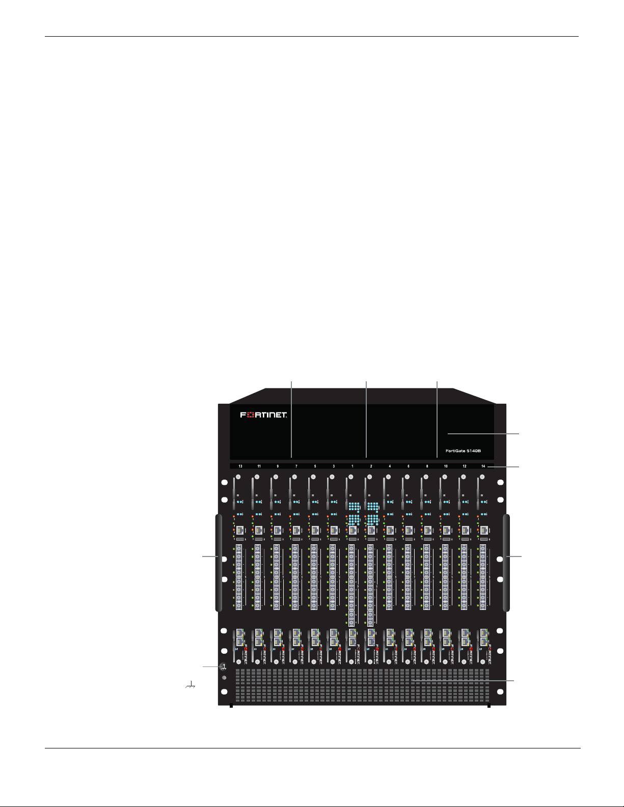
Figure 1 shows the front of a FortiGate-5140B chassis. Two FortiSwitch-5003B boards
are installed in slots 1 and 2 and 12 FortiGate-5001B boards are installed in slots 3 to 14.
Figure 1: FortiGate-5140B front panel with FortiGate-5001B and FortiSwitch-5003B
boards installed (cable tray not shown)
The following components are visible on the front of the FortiGate-5140B chassis:
FortiGate-5140B Chassis Guide
10 01-500-156415-20151104
http://docs.fortinet.com/
Page 11
FortiGate-5140B chassis FortiGate-5140B front panel
• The location of the four hot-swappable front replaceable cooling fans (behind the
cooling fan bay cover)
• The location of the front-replaceable air filter (behind the air intake bezel).
• The Electrostatic discharge (ESD) socket, used for connecting an ESD wrist band
when working with the chassis
• Chassis handles.
Do not operate the FortiGate-5140B chassis with open slots on the front panel. For
optimum cooling performance and safety, the chassis slots must contain a
FortiGate-5000 series board or an air baffle slot filler. For the same reason, all cooling
fan trays and the air filter should be installed while operating the chassis. As well both
PEMs must be installed in the back of the chassis.
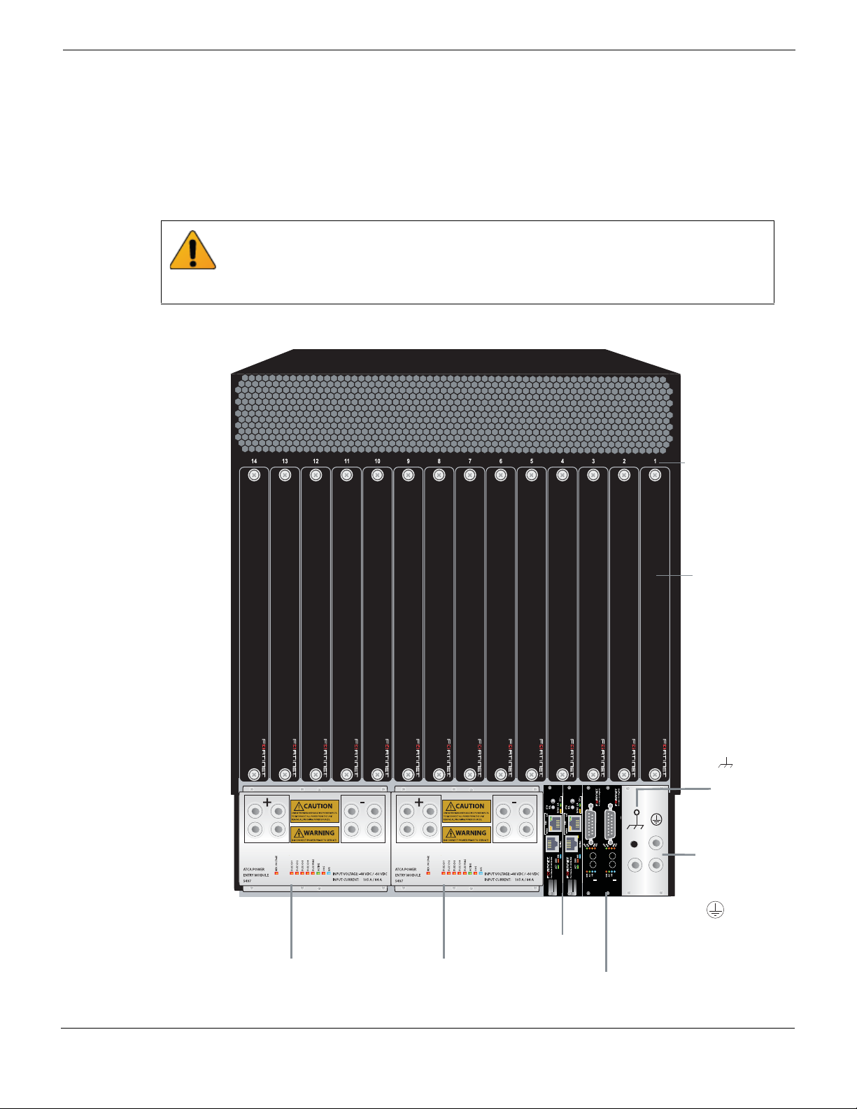
Figure 2: FortiGate-5140B chassis back panel (cable tray not shown)
RTM
slot numbers
RTM
air bafe
slot covers
ES D
socket
Chassis
ground
connector
(green)
RTN
(red)
-48/-60 VDC
nom (black)
RTN
(red)
-48/-60 VDC
nom (black)
Shelf
Power
Entry Module B
Power
Entry Module A
Managers
Shelf Alarm
Modules
FortiGate-5140B Chassis Guide
01-500-156415-20151104 11
http://docs.fortinet.com/
Page 12

FortiGate-5140B chassis back panel FortiGate-5140B chassis
FortiGate-5140B chassis back panel
Figure 2 shows the back of a FortiGate-5140B chassis.
The FortiGate-5140B chassis back panel includes two redundant -48V to - 60 VDC
power entry modules (PEMs). Fortinet ships the FortiGate-5140B chassis with both
installed. The PEMs provide redundant DC power connections for the FortiGate-5140B
chassis and distribute DC power to all chassis slots and components.
If you require redundant power you should connect both PEMs to DC power. If redundant
power is not required, you can connect one of them. Each PEM includes two power
terminals, one for connecting to -48V/-60 VDC (labelled -) and one for connecting to RTN
(labelled +). To connect power to the PEMs see, “Power connection and configuration”
on page 21.
The back panel also contains 14 RTM slots numbered to correspond to the front panel
slots. The RTM slots are available for FortiGate-5000 RTM modules. When the chassis is
shipped, these slots are covered by RTM air baffle slot covers.
The FortiGate-5140B Shelf Managers and the Shelf Alarm Modules (SAMs) are also
visible. The factory installed primary shelf manager provides power allocation, cooling,
alarms, and shelf status for the FortiGate-5140B chassis. The factory installed primary
and secondary Shelf Alarm Modules display alarms and provide telco alarm interfaces.
You can also install a secondary shelf manager as a backup for the primary one. For more
information about these components, see “FortiGate-5140B shelf managers” on page 14
and “FortiGate-5140B shelf alarm module” on page 16.
The back panel includes the FortiGate-5140B chassis ground connector which must be
connected to ground. The chassis also includes an ESD socket on the back panel.
Chassis hardware information
This section introduces FortiGate-5140B hardware components and accessories
including power requirements and FortiGate-5000 series boards that can be installed in
the chassis.
Shipping components
The FortiGate-5140B chassis ships pre-assembled with the following components (see
Figure 1 on page 10 and Figure 2 on page 11 for the location of the components in the
chassis):
• The 13U FortiGate-5140B chassis
• One shelf manager installed in the back of the chassis
• Two shelf alarm modules (SAMs) installed in the back of the chassis
• Two Power Entry Modules (PEMs) installed in the back of the chassis
• One air filter installed behind the air intake bezel at the bottom of the chassis
• Four cooling fans installed in the fan bays at the top of the chassis
• 13 front panel air baffle slot covers installed in the front panel slots
• 14 RTM air baffle slot covers installed in the RTM slots
• Four 3-ft. power cables with AWG-6 stranded wires and double-hole lugs: Black for
-48VDC and red for RTN. These cables should only be used to connect the
FortiGate-5140B PEMs to a FortiGate-5053B power convertor shelf if purchased with
your FortiGate-5140B chassis
FortiGate-5140B Chassis Guide
12 01-500-156415-20151104
http://docs.fortinet.com/
Page 13

FortiGate-5140B chassis Chassis hardware information
Supported FortiGate, FortiSwitch and FortiController ATCA boards
You can install the following FortiGate-5000 series boards in a FortiGate-5140B chassis
to provide security services. This includes the following:
ATCA board Interfaces Function
FortiGate-5001B Front Panel: 10 Gbps
Fabric: 10 Gbps
FortiGate-5001C Front Panel: 10 Gbps
Fabric: 10 Gbps
FortiGate-5101C Front Panel: 10 Gbps
Fabric: 10 Gbps
FortiGate-5001D Front Panel: 10 Gbps
Fabric: 40 Gbps
FortiSwitch-5203B Front Panel: 10 Gbps
Fabric: 10 Gbps
FortiController-5902B Front Panel: 10 Gbps
Fabric: 10 Gbps
FortiSwitch-5003B Front Panel: 10 Gbps
Fabric: 10 Gbps
FortiController-5103B Front Panel: 10 Gbps
Fabric: 10 Gbps
*Approximate values, see product datasheets for actual numbers.
FortiOS network
security
FortiOS network
security
FortiOS network
security
FortiOS network
security
Content clustering
with
FortiGate-5001Bs
Content clustering
with
FortiGate-5001Ds
Backplane switching,
FGCP HA, and
extended load
balancing (ELBC)
Session-aware load
balancing
Power Used
(WDC)*
Max: 225
Ave: 187
Max: 225
Ave: 187
Max: 226
Ave: 189
Max: 225
Ave: 187
Max: 250
Ave: 210
Max: 270
Ave: 223
Max: 180
Ave: 150
Max: 255
Ave: 213
Heat
Dissipation
(BTU/hr)*
768
768
774
768
853
919
614
754
The following older Fortinet ATCA boards can also be installed in the FortiGate-5140B
chassis:
• FortiGate-5001A
• FortiCarrier-5001A
• FortiGate-5005FA2
• FortiGate-5001FA2
• FortiGate-5001
• FortiGate RTM-XB2
• FortiGate RTM-XD2
• FortiSwitch-5003A
• FortiSwitch-5003
• FortiMail-5001A and 5002
• FortiManager-5001A
Power requirements
The FortiGate-5140B chassis is designed to be installed in a data center or similar
location that has available -48VDC power fed from a 100A listed circuit breaker (also
called battery power or main DC power). Fortinet expects that most FortiGate-5140B
customers will be installing their chassis in a data center or similar location that is already
equipped with a -48VDC power system fed from a 100A listed circuit breaker that
provides power to existing networking or telecom equipment. The FortiGate-5140B
chassis is designed to be connected directly to this DC power system.
FortiGate-5140B Chassis Guide
01-500-156415-20151104 13
http://docs.fortinet.com/
Page 14

FortiGate-5140B shelf managers FortiGate-5140B chassis
If DC power is not available you can use one or more FortiGate-5053B power converter
shelves equipped with PSU-5000B power supplies to convert AC to DC to supply DC
power to the FortiGate-5140B chassis from an AC source.
Physical description of the FortiGate-5140B chassis
The FortiGate-5140B chassis is a 13U chassis that can be installed in a standard 19-inch
rack. Ta bl e 1 describes the physical characteristics of the FortiGate-5140B chassis.
Table 1: FortiGate-5140B chassis physical description
Dimensions 22.63 x 19 x 22.6 in. (57.5 x 48.3 x 57.4 cm) (H x W x D)
Shipping weight completely
assembled with packaging
Chassis weight completely
assembled with shelf
manager and air baffles (13
front and 14 RTM)
PEM DC terminal torque No more than 3.8 Nm (33.62 lbf.in)
Operating environment
110 lbs (50 kg)
84 lbs (38 kg)
Temperature (long term): 41 to 104°F (+5 to 40°C)
Temperature (short term): 23 to 131°F (-5 to 45°C)
Power consumption
Power input 2x redundant -48 Vdc/-60Vdc, 100A-84A per PEM
Overcurrent Protection
Cooling Capacity
Protected Earth Test EN60950-1, test current 25 A, resistance <100 mOhm
Hipot Test EN60950-1, 1000 V
FortiGate-5140B shelf managers
The FortiGate-5140B chassis includes one or two redundant hot-swappable shelf
managers, located in the dedicated shelf manager slots at the bottom right side of the
back panel. The primary shelf manager is installed on the left the secondary shelf
manager (if present) is installed on the right. The secondary shelf manager is optional.
Relative humidity: 5 to 85% (Non-condensing)
Maximum: 530 W (Power consumed by an empty
chassis with four fans, one shelf manager, two shelf
alarm modules and two PEMs installed and operating
with the fans running at full speed.)
Each PEM includes 5 power channels. Each channel
includes its own 100 A fuse.
Front Boards: 300 W per board
RTM: 35 W per module
FortiGate-5140B Chassis Guide
14 01-500-156415-20151104
http://docs.fortinet.com/
Page 15
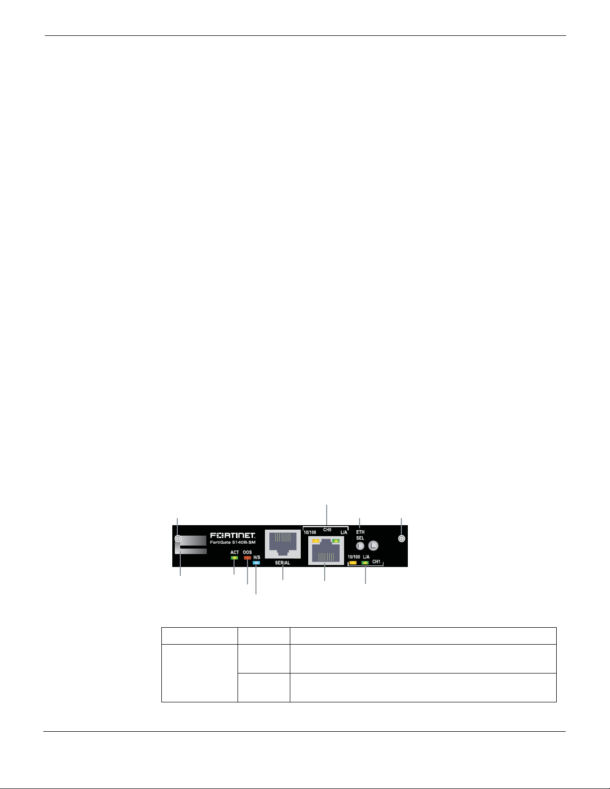
FortiGate-5140B chassis FortiGate-5140B shelf managers
Retention
Screw
Ethernet CH0 network
activity LEDs
Ethernet CH1 network
activity LEDs
RS-232
Serial
CH0 and 1
100base-T
Ethernet
Active (Green)Hot Swap
Actuator
Ethernet
Channel Selector
Retention
Screw
Out of Service (Red)
Hot Swap (Blue)
The shelf managers support redundant operation with automatic switchover. If both shelf
managers are operating normally, one acts as the active shelf manager and the other as
the standby. Usually the primary shelf manager would be the active shelf manager and
the secondary shelf manager would be the standby. The shelf managers monitor each
other and either can trigger a switchover if necessary. The active shelf manager performs
all shelf manager functions. If the active shelf manager fails or is removed, the standby
shelf manager takes over all shelf manager functions. If one shelf manager fails or is
removed the other will operate independently and the chassis will continue to function
normally.
The shelf managers control chassis power allocation, monitor chassis operating
parameters, monitor and control chassis cooling, and can signal alarms if the chassis
encounters problems. All FortiGate-5000 boards installed in the chassis communicate
with the shelf managers.
The shelf managers are factory installed. In most cases users do not have to install or
configure the shelf managers.
Each shelf manager has two ethernet interfaces (CH0 and CH1). Both channels connect
to the chassis backplane.
• When the Ethernet channel selector button is pushed in (recessed) CH0 connects to
the backplane.
• When the Ethernet channel selector button is pulled out you can use the front panel
Ethernet connector to connect to CH0.
Each shelf manager also has an RS-232 serial port for connecting to the shelf manager
console CLI.
The shelf managers detect alarm conditions and communicate alarm signals to the
FortiGate-5140B shelf alarm module.
The shelf managers are hot swappable. You remove a shelf manager by loosening the
retention screw that positions the hot swap actuator. This disengages the hot swap
switch and puts the shelf manager into hot swap mode. The hot swap LED starts blinking
blue. When the hot swap LED turns solid blue you can completely loosen both retention
screws and remove the shelf manager from the chassis.
Figure 3: FortiGate-5140B shelf manager front panel
Table 2: FortiGate-5140B shelf manager LEDs
LED State Description
Solid
Indicates that this is the active shelf manager.
Green
FortiGate-5140B Chassis Guide
01-500-156415-20151104 15
http://docs.fortinet.com/
ACT (Active)
Blinking
Green
Indicates that this is the standby shelf manager.
Page 16

FortiGate-5140B shelf alarm module FortiGate-5140B chassis
Table 2: FortiGate-5140B shelf manager LEDs
LED State Description
OOS (Out of
Service)
H/S (Hot
Swap)
10/100 (CH0
and CH1)
L/A
(Link/Activity
for CH0 and
CH1)
Off Normal Operation.
Red Shelf manager software reboot or other failure.
Off Normal operation.
Blinking
Blue
Blue The shelf manager can be removed from the chassis.
Amber 10/100 Mbit link for Ethernet CH0 or CH1.
Green Link/activity for Ethernet CH0 or CH1.
Using the shelf manager CLI
You can use the shelf manager command line interface (CLI) to communicate with the
intelligent management controllers of the chassis, with boards in the chassis, and with
the shelf manager itself. The CLI is an IPMI-based set of commands that can be
accessed directly or through a higher-level management application or a script. Using the
CLI, you can access information about the current state of the chassis including current
board population, current sensor values, threshold settings, recent events, and overall
chassis health.
To get started using the shelf manager CLI, see “Using the shelf manager CLI” on
page 34.
The shelf manager is shutting down in preparation for
being removed from the chassis.
Shelf Manager fan and power control
The FortiGate-5140B shelf managers monitor the internal temperature of the
FortiGate-5140B chassis and adjust the operating speed of the cooling fans as required.
When the chassis is first powered on all cooling fans run at full speed. Once the shelf
manager is up and running, the shelf manager reduces cooling fan speeds to maintain an
optimum temperature in the chassis. If shelf managers are not installed or not operating
correctly the FortiGate-5140B chassis cooling fans always operate at full speed.
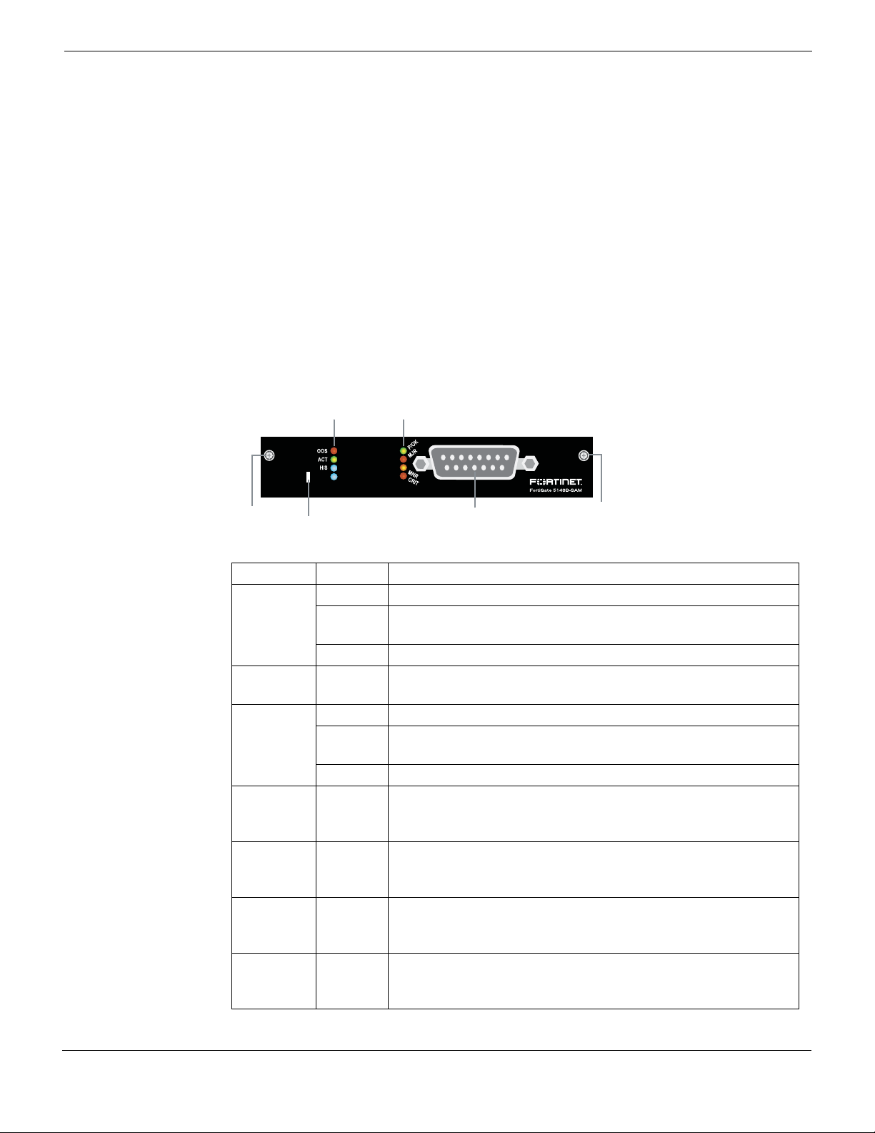
FortiGate-5140B shelf alarm module
The FortiGate-5140B chassis includes two redundant hot-swappable shelf alarm
modules (SAMs) each of which provide LED indicators of FortiGate-5140B alarms, a telco
alarm connector, and an alarm LED reset buttons. The LED alarm indicators include
critical, major, and minor alarms.
FortiGate-5140B Chassis Guide
16 01-500-156415-20151104
http://docs.fortinet.com/
Page 17
FortiGate-5140B chassis FortiGate-5140B shelf alarm module
Retention
Screw
Reset
Retention
Screw
Telco Alarm
Interface
Out of Service (Red)
Active (Green)
Hot Swap (Blue)
Power OK (Green)
Major Alarm (Red)
Minor Alarm (Amber)
Critical Alarm (Red)
The shelf alarm modules support redundant operation with automatic switchover. If both
shelf alarm modules are operating normally, one acts as the active shelf alarm module
and the other as the standby. Usually the primary shelf alarm module would be active and
the secondary module would be the standby. The shelf alarm modules monitor each
other and either can trigger a switchover if necessary. By default the shelf alarm module
on the left is the active one. The active shelf alarm module performs all shelf alarm
functions. If the active shelf alarm module fails or is removed, the standby shelf alarm
module takes over all functions.
The Telco Alarm Interface is a standard DB-15 male Telco Form-c connector. The external
dry relay Telco alarm interface (48VDC) provides Telco form-c relay connections for minor,
major and critical power faults. The cable required to connect to the alarm interface is not
supplied by Fortinet. To monitor alarms you should connect to the telco alarm interface of
the active shelf alarm panel, which by default is the one on the left.
Figure 4: FortiGate-5140B shelf alarm module front panel
Table 3: FortiGate-5140B shelf alarm module LEDs
LED State Description
Off Normal operation.
OOS (Out
of Service)
Blinking
Red
Lost connection to the shelf manager or no IPBM bus.
Red Incorrect hardware address or FRU data corruption.
ACT
Green Normal operation.
(Active)
Off Normal operation.
H/S (Hot
Swap)
Blinking
Blue
The shelf manager is shutting down in preparation for being
removed from the chassis.
Blue The shelf alarm module can be removed from the chassis.
POK
Green Input power to the chassis is within limits.
(Power
OK)
MJR
Red Major alarm detected in chassis.
(Major
Alarm)
MNR
Amber Minor alarm detected in chassis.
(Minor
Alarm)
CRIT
Red Critical alarm detected in chassis.
(Major
Alarm)
FortiGate-5140B Chassis Guide
01-500-156415-20151104 17
http://docs.fortinet.com/
Page 18
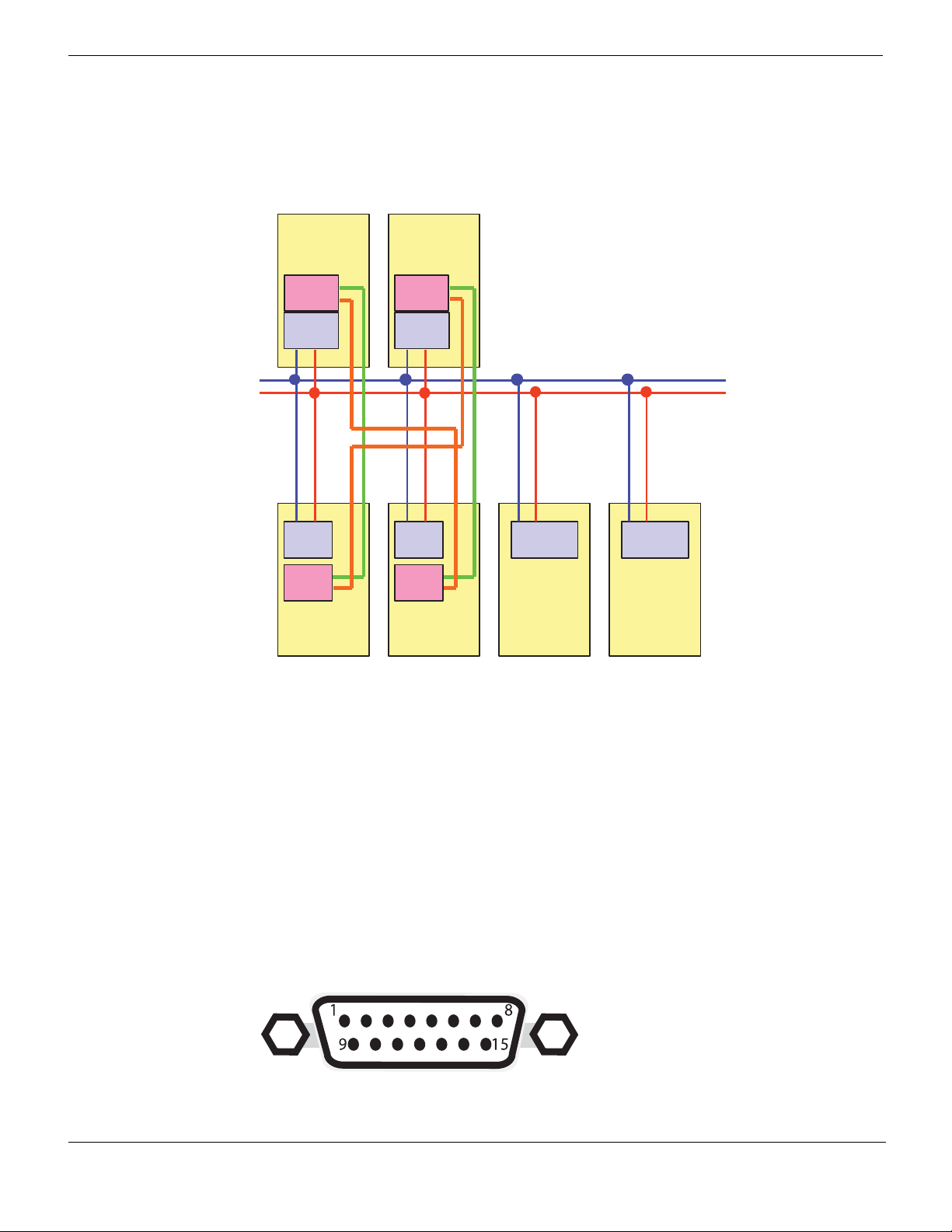
FortiGate-5140B shelf alarm module FortiGate-5140B chassis
Eth port0
Eth port1
Eth port0
Eth port1
ShMC port1
ShMC port2
ShMC port1
ShMC port2
Base Hub A
ShMC
IPMC IPMC IPMC IPMC
ShMC
Shelf
Manager
(active)
Shelf
Manager
(backup)
Base Hub B ATCA board
Redundant IPMB-0 on Backplane
ATCA board
Figure 5 shows the connections between the primary and secondary shelf managers and
the shelf alarm panel.
Figure 5: Ethernet connections between shelf managers and the base backplane
interfaces
Shelf alarm panel telco alarms
The shelf alarm panel telco alarm interface relay circuits are capable of carrying 60 VDC
or 1 A with a max. rating of 30 VA. The shelf alarm panel accepts timed pulse inputs for
clearing minor and major alarm states. Reset is accomplished by asserting a voltage
18 01-500-156415-20151104
differential from 3.3 V to 48 V for between 200 and 300 ms. The acceptance voltage
range is from 0 to 48 VDC continuous (handles up to 60 VDC at a 50% duty cycle). The
current drawn by a reset input does not exceed 12 mA.
The alarm LED reset button activates the alarm cutoff (ACO) state for major, minor, and
user-defined alarms. You cannot reset critical alarms with the alarm LED reset button.
When the ACO state is activated, active alarm LEDs blink and all of the alarm relays are
deactivated. The alarm reset button activates the ACO state but does not clear the alarm
completely.
Figure 6: The telco alarm connector (DB-15 male)
FortiGate-5140B Chassis Guide
http://docs.fortinet.com/
Page 19

FortiGate-5140B chassis Air filter
Table 4: Telco alarm connector pin assignment
Pin Description
1 MinorReset+
2 MinorReset-
3MajorReset+
4MajorReset-
5 CriticalAlarm - NO
6Critical Alarm NC
7Critical Alarm COM
8 Minor Alarm NO
9 Minor Alarm NCt
10 Minor Alarm COM
11 Major Alarm NO
12 Major Alarm NC
13 Major Alarm COM
14 Power NO
15 Power COM
Air filter
The FortiGate-5140B chassis includes a front replaceable air filter that removes dust from
intake air and provides static pressure to achieve uniform airflow. The filter must be
installed for the chassis to operate normally. If the air filter is not locked into place the
redundant air filter presence sensors cause an alarm.
Air filters should be inspected regularly. If dirty or damaged, the filter should be disposed
of and replaced. The air filter can be fragile and should be handled carefully.
To service the air filter you must remove the air intake bezel at the bottom of the front of
the chassis. See Figure 1 on page 10 for the location of the air intake bezel and air filter.
The bezel is held in place by four torq screws which must be loosened before the bezel
can be removed. The air filter can be removed using the lower flange as a handle. Gently
push the filter and tilt it down to remove it.
Care should be taken when inserting an new air filter to prevent damage to the sensors.
To insert a new filter, slide it along the guide rails at each side of the shelf until the filter
contacts springs at the back of the chassis. Then tilt the filter up until it locks into place
under the card cage. Pull the filter forward to make sure it is locked into place.
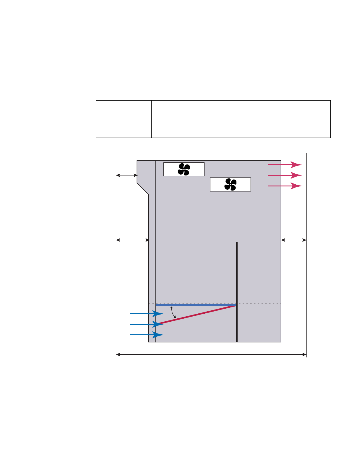
Cooling fans, cooling air flow, and minimum clearance
The FortiGate-5140B chassis contains four identical hot-swappable cooling fans installed
in the fan cabinet at the top of the chassis. See Figure 1 on page 10 for the location of the
cooling fans. Two fans are installed at the top of the cabinet and two at the bottom. The
fans at the bottom of the cabinet are not directly under the fans at the top, but are located
further towards the back of the cabinet. To be able to reach the bottom fans long handles
are attached to them so that you don’t have to insert your hand into the chassis to access
them.
FortiGate-5140B Chassis Guide
01-500-156415-20151104 19
http://docs.fortinet.com/
Page 20
Cooling fans, cooling air flow, and minimum clearance FortiGate-5140B chassis
100 mm
600 mm
600 mmCool air
Intake
Warm air
Exhaust
60 mm
40 mm
Front
Back
Air Filter
(normal operation)
Air Filter
(Tilted down to
remove or insert)
Fan
Fan
To service the fans, open the latches on either side of the fan cabinet and open the cover
by pulling it down. Access the top fans by pulling them out. Access the bottom fans by
pulling them out by their handles.
You do not need to press a hot swap switch to remove a fan. Just pull it out of the fan
cabinet. The shelf manager regulates the fan speed by adjusting the DC voltage supplied
to the fan trays.
Table 5: FortiGate-5140B fan tray LEDs
LED Description
HS (Hot Swap) Normally off. Blinking blue indicates that the fan is starting up.
OOS (Out of
Service)
Normally off. Blinking red indicates the fan is out of service and
should be replaced.
Figure 7: Cooling air flow and required minimum air flow clearance
When installing the chassis, make sure there is enough clearance for effective cooling air
flow. See Figure 7 on page 20 for the minimum clearance requirements. The diagram also
shows the cooling air flow through the chassis and the location of the air filter and cooling
fans. Make sure the cooling air intake and warm air exhaust openings are not blocked by
cables or rack construction because this could result in cooling performance reduction
and possible overheating and component damage.
20 01-500-156415-20151104
FortiGate-5140B Chassis Guide
http://docs.fortinet.com/
Page 21

FortiGate-5140B
Power connection and configuration
This chapter describes how to connect DC power to a FortiGate-5140B chassis.
The FortiGate-5140B chassis is designed to be installed in a data center or similar
location that has available -48VDC power fed from a 100A listed circuit breaker (also
called battery power or main DC power). Fortinet expects that most FortiGate-5140B
customers will be installing their chassis in a data center or similar location that is already
equipped with a -48VDC power system fed from a 100A listed circuit breaker that
provides power to existing networking or telecom equipment. The FortiGate-5140B
chassis is designed to be connected directly to this DC power system.
If DC power is not available at the location in which the FortiGate-5140B chassis is to be
installed you can use the FortiGate-5053B power converter shelf to convert AC to DC to
supply DC power to the FortiGate-5140B chassis.
Fortinet supplies four 3-ft. power cables with AWG-6 stranded wires and double-hole
lugs: Black for -48VDC and red for RTN. These cables should only be used to connect
the FortiGate-5140B PEMs to a FortiGate-5053B power convertor shelf if purchased with
your FortiGate-5140B chassis. The double-hole lugs to be connected to the
FortiGate-5140B PEMs include rubber boots that should be installed before energizing
the power system. If the power cable length needs to be longer than 3 ft., higher gauge
wires should be considered.
If you are connecting your chassis to a local DC power source, use cables that meet your
local wiring codes. To connect the wires to the FortiGate-5140B PEMs use 3/4-inch
double-hole lugs with insulating boot suitable the DC cables used, such as Thomas &
Betts PN 256-30695-1225.
Green AWG-6 wires are recommended for ground connections (not supplied with the
chassis).
This chapter describes:
• FortiGate-5140B chassis power level requirements
• Connecting the FortiGate-5140B chassis to DC power and ground
• Connecting a FortiGate-5140B PEM to DC power
• Connecting the FortiGate-5140B chassis to ground
• Supplying power using the FortiGate-5053B power supply shelf and PSU-5000B
power supplies
• Turning on FortiGate-5140B chassis power
FortiGate-5140B chassis power level requirements
This section provides some basic information for determining the power requirements of
your FortiGate-5140B chassis. This section provides guidelines only. Actual requirements
may vary depending on your installation requirements. Contact Fortinet Support if you
need more information.
FortiGate-5140B Chassis Guide
01-500-156415-20151104 21
http://docs.fortinet.com/
Page 22
Connecting the FortiGate-5140B chassis to DC power and ground Power connection and configuration
The base FortiGate-5140B chassis (empty, with four fans, one shelf manager, two shelf
alarm modules and two PEMs installed and operating with the fans running at full speed)
requires a maximum of 530 W. Each chassis slot can supply up to 300 W. You can use
these numbers to estimate the power requirement for a chassis configuration.
Example: power for a chassis with 5 boards
For example, the power requirement for a FortiGate-5140B chassis with FortiGate,
FortiSwitch, or FortiController boards in five slots would be:
530W + (300W * 5) = 2030W
Example: power for a fully-loaded chassis (14 boards)
The power requirement for a fully loaded FortiGate-5140B chassis with boards in all 14
slots would be:
530W + (300W * 14) = 4730W
Connecting the FortiGate-5140B chassis to DC power and ground
Connect the FortiGate-5140B chassis to DC power using the redundant -48V to - 60 VDC
power entry modules (PEMs) at the bottom of the chassis back panel. The specified
voltage range of the PEMs is -40 VDC to -72 VDC. The chassis ships with both PEMs
installed. The PEMs provide redundant DC power connections for the FortiGate-5140B
chassis and distribute DC power to all chassis slots and components.
The PEM includes a Reverse Voltage LED that lights if you have reversed the polarity
when connecting power.
Each FortiGate-5140B PEM includes four -48V/-60 VDC (labeled as - and connected
together internally) and four return connectors (labeled as + and connected together
internally). Each PEM supplies 5 power channels. Each channel includes a separate 30A
fuse to power a group of 3 to 4 chassis slots or a 20A fuse for fans and Shelf Managers.
All terminals should be connected single -48VDC power source with a 100A listed circuit
breaker.
To connect the FortiGate-5140B PEMs to DC power you must use power connectors and
wires that comply with the local electrical wiring code and the requirements of the facility
in which you are installing the FortiGate-5140B chassis.
The PEMs are hot-swappable, which means you can remove and replace a defective
PEM while the system is operating (assuming that the FortiGate-5140B system has both
PEMs connected for redundancy). It is not necessary to notify the software or reset the
system power to remove a PEM. You can add, remove, or replace a second PEM without
interrupting FortiGate-5140B operation.
FortiGate-5140B Chassis Guide
22 01-500-156415-20151104
http://docs.fortinet.com/
Page 23
Power connection and configuration Connecting a FortiGate-5140B PEM to DC power
DC Power Source
-48VDC
connector
RTN (+)
red to power
source RTN
DC Power Source
RTN connector
-48V/-60 VDC
black to power
source -48VDC
Reverse Voltage LED
Fuse LEDs
Active OOS H/S
Crimping guidelines
To connect the PEMs to datacenter power you should use AWG-6 or larger wires
depending on the length and the power requirements of your chassis. The ends of these
wires must be fitted with 3/4-inch double-hole lugs with insulating boot suitable the DC
cables used, such as Thomas & Betts PN 256-30695-1225. Use the following information
to crimp and prepare these wires.
Do not crimp energized wires.
Before crimping, slide rubber boot along each wire. Follow these crimping guidelines:
• Strip the insulation from cable. Be careful not to nick cable strands which may later
result in stands breaking
• Cable end should be clean: wire brush or clean with emery cloth if necessary. Insert
cable into connector until it stops. The insertion length must approximate the stripped
length of cable
• Insert connector in die and compress between the markings beginning near the
tongue of the connector. Using the wrong installing die may result in a defective
connection.
• After crimping, remove all sharp edges, flash or burrs.
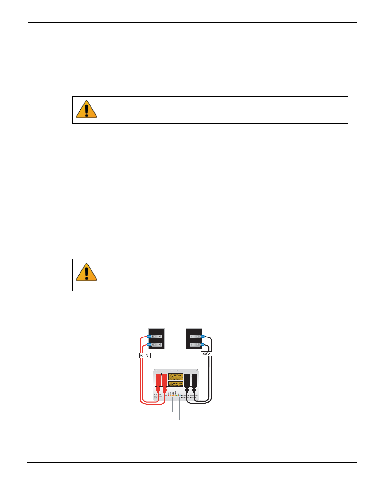
Connecting a FortiGate-5140B PEM to DC power
The following procedure describes how to connect power to a PEM. You can repeat this
procedure for both PEMs.
Two DC cable sets are required for each PEM connection (and all 4 terminals on each
polarity should be used). If for any reason any of the PEM terminals are not used the
unused terminals need to be covered with insulated material (or wrapped with electrical
tape) as the exposed terminals are a shock hazard.
Figure 8: Connecting a FortiGate-5140B PEM to DC power
FortiGate-5140B Chassis Guide
01-500-156415-20151104 23
http://docs.fortinet.com/
Page 24

Connecting a FortiGate-5140B PEM to DC power Power connection and configuration
Table 6: FortiGate-5140B PEM LEDs
LED State Description
REV. VOLTAGE
(Reverse
Voltage)
Off Normal operation
Solid Red Input voltage polarity reversed.
Off Normal operation.
FUSE CH1-4
(Fuses for power
channels 1 to 4)
Solid Red Fuse blown or absent.
Blinking
Input power lost
Red
FUSE FANS
(Fuses for the
cooling fan
power channel)
Off Normal operation.
Solid Red Fuse blown or absent.
Blinking
Input power lost.
Red
If all five fuse LEDs are simultaneously blinking input power to the PEM has been lost.
ACTIVE
Solid
Green
Normal operation.
Off Normal Operation.
OOS (Out of
Service)
Blinking
Red
Lost connection to shelf manager or IPMB bus.
Solid Red Incorrect hardware address or FRU data corruption.
Off Normal operation.
H/S (Hot Swap)
Blinking
Blue
The PEM is shutting down in preparation for being
removed from the chassis.
Blue The PEM can be removed from the chassis.
You need the following equipment to connect a FortiGate-5140B PEM to DC power:
• An electrostatic discharge (ESD) preventive wrist strap with connection cord.
• Two black AWG-6 stranded wires labelled -48V with attached 3/4-inch listed closed
loop double-hole lugs with insulating boot suitable for the DC cables used, such as
Thomas & Betts PN 256-30695-1225.
• Two red AWG-6 stranded wires labelled RTN with attached 3/4-inch listed closed loop
double-hole lugs with insulating boot suitable for he DC cables used, such as Thomas
& Betts PN 256-30695-1225.
To connect a FortiGate-5140B PEM to DC power
1 Attach the ESD wrist strap to your wrist and to an ESD socket or to a bare metal
surface on the chassis or frame.
2 Make sure that the PEM and power cord are not energized.
3 Remove the first set of nuts and lock washers from both connectors on the PEM.
4 Connect two black -48V power wires from the DC power source to the connectors on
the FortiGate-5140B PEM labeled - (the connectors on the right side of the PEM)
using the double-hole lugs (see Figure 8).
Install each double-hole lug vertically. Do not apply torque of more than 3.8 Nm (33.62
lbf.in).
FortiGate-5140B Chassis Guide
24 01-500-156415-20151104
http://docs.fortinet.com/
Page 25
Power connection and configuration Connecting the FortiGate-5140B chassis to ground
Data Center
ground
connector
(Central ofce
ground sys tem)
Chassis
Ground
Connector
(green)
5 Connect two red RTN power wires from your location’s RTN terminal to the
connectors on the FortiGate-5140B PEM labeled + (the connectors on the left side of
the PEM) using the double-hole lug (see Figure 8).
Install each double-hole lug vertically. Do not apply torque of more than 3.8 Nm (33.62
lbf.in).
6 Install previously removed nuts and washers to secure the connectors.
7 Cover the connectors with rubber boots.
8 Make sure the power wires are secured using tie wraps if required.
9 If required, label the black wires -48V.
10 If required, label the red wires RTN.
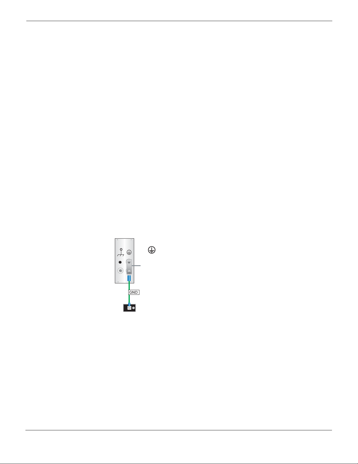
Connecting the FortiGate-5140B chassis to ground
The FortiGate-5140B chassis includes a ground terminal on the lower right side of the
FortiGate-5140B back panel (see Figure 2 on page 11). The ground terminal provides two
connectors to be used with a double-holed lug such as Thomas & Betts PN 256-30695-
1225. This connector must be connected to a local ground connection.
You need the following equipment to connect the FortiGate-5140B chassis to ground:
• An electrostatic discharge (ESD) preventive wrist strap with connection cord.
• One green AWG-6 stranded wire with listed closed loop double-hole lug with
insulating boot suitable for minimum 6 AWG copper wire, such as Thomas & Betts PN
256-30695-1225.
Figure 9: Connecting a FortiGate-5140B chassis to ground
To connect the FortiGate-5140B chassis to ground
1 Attach the ESD wrist strap to your wrist and to an ESD socket or to a bare metal
surface on the chassis or frame.
2 Make sure that the chassis and ground wire are not energized.
3 Connect the green ground wire from the local ground to the ground connector on the
FortiGate-5140B chassis (see Figure 9).
4 Secure the ground wire to the chassis.
5 Optionally label the wire GND.
FortiGate-5140B Chassis Guide
01-500-156415-20151104 25
http://docs.fortinet.com/
Page 26
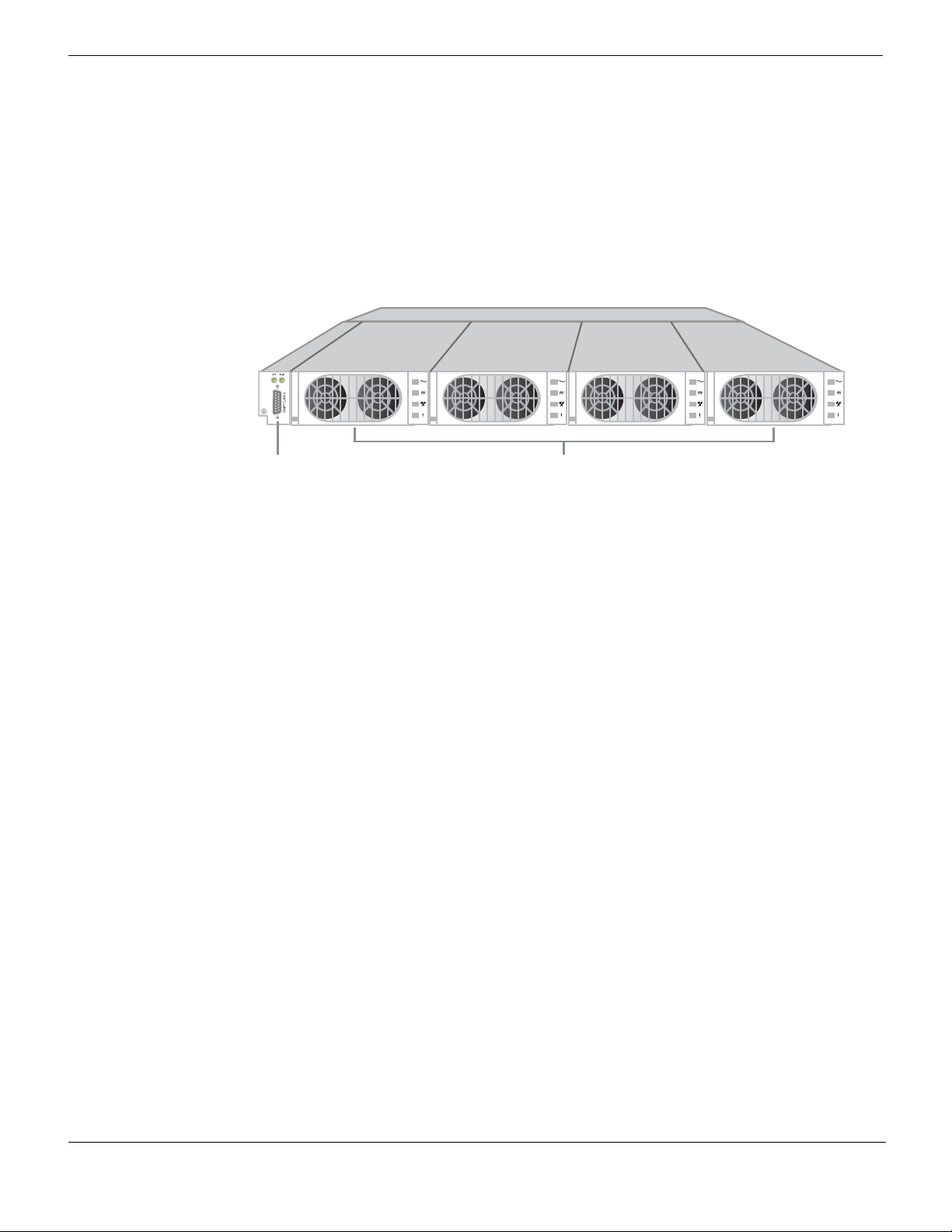
Supplying power using the FortiGate-5053B power supply shelf and PSU-5000B power supplies Power connection and
PS U-5000B hot swappable
Power Supplies (4)
Edge
Controller
Supplying power using the FortiGate-5053B power supply shelf and PSU-5000B power supplies
If DC power is not available at your location, you can use the FortiGate-5053B and
FortiGate-5053B-LC 1U 19-inch rack mount power supply shelves with PSU-5000B hot
swappable power supplies to convert AC power to DC power. These components are not
supplied with the FortiGate-5140B chassis and must be purchased separately.
Figure 10: FortiGate-5053B power supply shelf with four PSU-5000B power supplies
As already stated, Fortinet supplies four 3-ft. power cables with AWG-6 stranded wires
and double-hole lugs: Black for -48VDC and red for RTN. These cables should only be
used to connect the FortiGate-5140B PEMs to a FortiGate-5053B power supply shelf if
purchased with your FortiGate-5140B chassis. The double-hole lugs to be connected to
the FortiGate-5140B PEMs include rubber boots that should be installed before
energizing the power system. If the power cable length needs to be longer than 3 ft.,
higher gauge wires should be used.
The FortiGate-5053B power supply shelf can include up to four PSU-5000B power
supplies. The power supply shelf can be connected to high line AC input (186-240VAC) or
low line AC input (100-185VAC).
• When connected to high-line AC input, a single power supply can provide 2725W of
DC power and a fully populated FortiGate-5053B power supply shelf can provide up
to 10.9KW of DC power and 8175W of DC power with 3+1 redundancy with an output
voltage of 54 VDC.
• When connected to low-line AC input a single power supply can provide 1200W of DC
power and a fully populated FortiGate-5053B power supply shelf can provide up to
4800W of DC power and 3600W of DC power with 3+1 redundancy with an output
voltage of 54 VDC.
The FortiGate-5053B power supply shelf edge controller controls and manages the
power supplies, provides for redundancy, and provides a control and alarm
communication interface for the power supply shelf.
For a more information about the FortiGate-5053B power supply shelf see the FortiGate-
5053B Power Supply Shelf Guide.
To supply power to a FortiGate-5140B chassis you must connect one FortiGate-5053B
power supply shelf to one FortiGate-5140B PEM.
You can install extra PSU-5000B power supplies in a single FortiGate-5053B power
supply shelf to provide power redundancy. If a PSU-5000B fails or is removed a backup
PSU-5000B will continue to supply power.
For a completely redundant power supply you can connect a second FortiGate-5053B
power supply shelf to the second FortiGate-5140B PEM.
FortiGate-5140B Chassis Guide
26 01-500-156415-20151104
http://docs.fortinet.com/
Page 27

Power connection and configuration Supplying power using the FortiGate-5053B power supply shelf and PSU-5000B power
Selecting the power supplies and power supply shelves that you need for your FortiGate-5140B chassis
This section provides some basic information for determining the power requirements of
your FortiGate-5140B chassis. Using these power requirements you can decide how
many PSU-5000B power supplies and FortiGate-5053Bpower supply shelves you need
to provide that power. This section provides guidelines only. Actual requirements may
vary depending on your installation requirements. Contact Fortinet Support if you need
more information.
The base FortiGate-5140B chassis (empty, with four fans, one shelf manager, two shelf
alarm modules and two PEMs installed and operating with the fans running at full speed)
requires a maximum of 530 W. Each chassis slot can supply up to 300 W. You can use
these numbers to estimate the power requirement for a chassis configuration.
Example: power for a chassis with 5 boards
For example, the power requirement for a FortiGate-5140B chassis with FortiGate,
FortiSwitch, or FortiController boards in five slots would be:
530 W + (300 W * 5) = 2030 W
If you are using high-line AC power, one PSU-5000B produces 2725W. Powering a
chassis with 5 boards would require one FortiGate-5053B power supply shelf connected
to one PEM. The power supply shelf would include one PSU-5000B unit. You can add a
second power supply for redundancy. If you want completely redundant power for the
chassis you can connect a second FortiGate-5053B unit to the other FortiGate-5140B
PEM and include one or two power supplies.
If you are using low-line AC power, one PSU-5000B produces 1200W. Powering a
chassis with 5 boards would require one FortiGate-5053B power supply shelf connected
to one PEM. The power supply shelf would include two PSU-5000B units. You can add a
third power supply for redundancy. If you want completely redundant power for the
chassis you can connect a second FortiGate-5053B unit to the other FortiGate-5140B
PEM and include two or three power supplies.
Example: power for a fully-loaded chassis (14 boards)
The power requirement for a fully loaded FortiGate-5140B chassis with boards in all 14
slots would be:
530 W + (300 W * 14) = 4730 W
If you are using high-line AC power, one PSU-5000B produces 2725W. Powering a
chassis with 14 boards would require one FortiGate-5053B power supply shelf
connected to one PEM. The power supply shelf would include two PSU-5000B units and
produce a total of 3450W. You can add a third power supply for redundancy. If you want
completely redundant power for the chassis you can connect a second FortiGate-5053B
unit to the other FortiGate-5140B PEM and include two or three power supplies.
If you are using low-line AC power, one PSU-5000B produces 1200W. Powering a
chassis with 14 boards would require one FortiGate-5053B power supply shelf
connected to one PEM. The power supply shelf would include four PSU-5000B units. If
you want redundant power for the chassis you can add a second FortiGate-5053B unit
connected to the other FortiGate-5140B PEM and include four power supplies.
FortiGate-5140B Chassis Guide
01-500-156415-20151104 27
http://docs.fortinet.com/
Page 28

Supplying power using the FortiGate-5053B power supply shelf and PSU-5000B power supplies Power connection and
Connecting a FortiGate-5140B chassis to the FortiGate-5053B power supply shelf
To use a FortiGate-5053B power supply shelf with the FortiGate-5140B chassis you need
to make DC power connections between A FortiGate-5140B PEM and the
FortiGate-5053B power supply shelf. You also need to the connect the FortiGate-5140B
chassis and the FortiGate-5053B power supply shelf to ground.
If your configuration requires a FortiGate-5053B-LC unit you must also connect it to the
FortiGate-5140B PEM.
Connecting a FortiGate-5140B chassis to a single FortiGate-5053B power supply shelf
The following procedure describes how to connect power to one FortiGate-5140B PEM
using the FortiGate-5053B power supply shelf. You can repeat this procedure to connect
the other PEM to a second FortiGate-5053B power supply shelf.
You need the following equipment:
• An electrostatic discharge (ESD) preventive wrist strap with connection cord.
• Two black AWG-6 stranded wires labelled -48V with attached Listed closed loop
double-hole lugs with insulating boot suitable for minimum AWG-6 copper wire
(supplied by Fortinet), such as Thomas & Betts PN 256-30695-1225
• Two red AWG-6 stranded wires labelled RTN with attached Listed closed loop doublehole lugs with insulating boot suitable for minimum AWG-6 copper wire, such as
Thomas & Betts PN 256-30695-1225.
• A FortiGate-5053B power supply shelf containing the required number of PSU-5000B
power supplies and mounted in a rack near the FortiGate-5140B chassis.
To connect a FortiGate-5140B power input connector to a FortiGate-5053B power
supply shelf
The FortiGate-5053B power converter shelf should not be connected to AC power until
specified in the following procedure.
1 Attach the ESD wrist strap to your wrist and to an ESD socket or to a bare metal
surface on the chassis or frame.
2 Make sure that the PEM, power supply shelf and DC power cable are not energized.
3 Remove the first set of nuts and lock washers from both connectors on the back of
the FortiGate-5053B power supply shelf.
4 Connect two black -48V power wires to the connectors labelled NEG on the back of
the FortiGate-5053B power supply shelf using the double-hole lug (see Figure 11).
Install each double-hole lug either horizontally or vertically. Do not apply torque of
more than 3.8 Nm (33.62 lbf.in).
5 Connect two black -48V power wires to the connectors labelled POS on the back of
the FortiGate-5053B power supply shelf using the double-hole lug (see Figure 11).
Install each double-hole lug either horizontally or vertically. Do not apply torque of
more than 3.8 Nm (33.62 lbf.in).
6 Install previously removed nuts and washers to secure the connectors.
7 Cover the connectors with the connector covers on the back of the power supply
shelf.
FortiGate-5140B Chassis Guide
28 01-500-156415-20151104
http://docs.fortinet.com/
Page 29

Power connection and configuration Supplying power using the FortiGate-5053B power supply shelf and PSU-5000B power
8 Select a PEM to connect power to and remove the first set of nuts and lock washers
from its connectors.
9 Connect the two black -48V power wires from the power supply shelf to the
connectors on the FortiGate-5140B PEM labeled - (the connectors on the right side of
the PEM) using the double-hole lug (see Figure 11).
Install each double-hole lug vertically. Do not apply torque of more than 3.8 Nm (33.62
lbf.in).
10 Connect two red RTN power wires from the power supply shelf to the connectors on
the FortiGate-5140B PEM labeled + (the connectors on the left side of the PEM) using
the double-hole lug (see Figure 11).
Install each double-hole lug vertically. Do not apply torque of more than 3.8 Nm (33.62
lbf.in).
11 Install previously removed nuts and washers to secure the connectors.
12 Cover the connectors with rubber boots.
Two DC cable sets are required for each PEM connection (and all 4 terminals on each
polarity should be used). If for any reason any of the PEM terminals are not used the
unused terminals need to be covered with insulated material (or wrapped with electrical
tape) as the exposed terminals are a shock hazard.
Figure 11: Connecting a FortiGate-5140B PEM to a FortiGate-5053B power supply
shelf
Red + to
FortiGate-5053B
POS
-48V/-60 VDC
- black to
FortiGate-5053B
NEG
13 Make sure the power wires are secured to the chassis using tie wraps if required.
14 If required, label the black wires -48V.
15 If required, label the red wires RTN.
16 Connect the FortiGate-5053B power supply shelf to AC power.
Only connect the power supplies that are installed in the FortiGate-5053B to AC
power. For example, if your FortiGate-5053 includes two power supplies, the power
supplies will be installed in slots 1 and 2. In this case you should only connect AC
connectors 1 and 2 to AC power. If your power supply shelf contains four power
supples, connect all four AC in connectors to AC power.
FortiGate-5140B Chassis Guide
01-500-156415-20151104 29
http://docs.fortinet.com/
Page 30

Turning on FortiGate-5140B chassis power Power connection and configuration
Data Center
ground
connector
(Central ofce
ground sys tem)
Shelf ground
connector
Connecting the FortiGate-5053B power supply shelf to ground
The FortiGate-5053B and LC power supply shelves both include ground terminals on the
center of the back panel (see Figure 12 on page 30). The ground terminal provides two
connectors to be used with a double-holed lug such as Thomas & Betts PN 256-30695-
1225. This connector must be connected to ground.
You need the following equipment to connect the FortiGate-5053B unit to ground:
• An electrostatic discharge (ESD) preventive wrist strap with connection cord.
• One green AWG-6 stranded wire with listed closed loop double-hole lug with
insulating boot suitable for minimum AWG-6 copper wire, such as Thomas & Betts PN
256-30695-1225.
Figure 12: Connecting a FortiGate-5053B power supply shelf to ground
To connect the FortiGate-5053B power supply shelf to ground
1 Attach the ESD wrist strap to your wrist and to an ESD socket or to a bare metal
surface on the chassis or frame.
2 Make sure that the shelf and ground wire are not energized.
3 Connect the green ground wire from the location’s ground terminal to the ground
connector on the power supply shelf (see Figure 12).
4 Secure the ground wire as required.
5 Optionally label the wire GND.
Turning on FortiGate-5140B chassis power
If you are using a power supply shelf, connect the power supply shelf to AC power and
verify that it is operating correctly.
If you are using local DC power, turn on the power to the chassis according to the
requirements of your local DC power system.
Once the FortiGate-5140B chassis is connected to DC power the chassis powers up. If
the chassis is operating correctly, the LEDs on the connected PEM(s) and fans should be
lit. As well, the LEDs on the FortiGate-5140B shelf manager and shelf alarm modules
should be lit (see Figure 3 on page 15).
When the chassis first starts up you should also hear the cooling fans operating.
In addition, if any FortiGate-5000 series boards have been installed in the chassis they
should power on and their front panel LEDs should indicate that they are starting up and
operating normally.
30 01-500-156415-20151104
FortiGate-5140B Chassis Guide
http://docs.fortinet.com/
Page 31

FortiGate-5140B
FortiGate-5140B hardware procedures
This chapter assumes the chassis has been mounted and connected to a power source
as detailed in “Power connection and configuration” on page 21.
This chapter discusses:
• Mounting the FortiGate-5140B chassis
• Inserting 5000 series boards and RTM modules into a FortiGate-5140B chassis
• Using FortiController-5103B boards for session-aware load balancing
• Using FortiSwitch-5003B boards for backplane communication
• Using FortiSwitch-5203B boards for content clustering
Mounting the FortiGate-5140B chassis
Mount the FortiGate chassis before installing the FortiGate-5000 series modules.
The FortiGate-5140B chassis must be mounted in a standard 19-inch rack. The chassis
requires 13U of vertical space in the rack.
If you install the FortiGate-5140B chassis in a closed or multi-unit rack assembly, the
operating ambient temperature of the rack environment may be greater than room
ambient temperature. Make sure the operating ambient temperature does not exceed the
manufacturer's maximum rated ambient temperature.
The FortiGate-5140B chassis should not be operated as a free-standing appliance.
Install the FortiGate-5140B chassis at the lower positions in the rack to avoid making the
rack top-heavy and potentially falling over.
Air flow
For rack installation, make sure that the amount of air flow required for safe operation of
the FortiGate-5140B chassis is not compromised. Make sure that the chassis ventilation
openings at the top rear and the bottom front are not blocked by cables or other
components. The recommended minimum clearance at the front of the chassis is
100 mm and the recommended clearance from the rear of the chassis is 60 mm. This
results in a total footprint of 600 mm from front to back. See “Cooling fans, cooling air
flow, and minimum clearance” on page 19 for more details.
FortiGate-5140B Chassis Guide
01-500-156415-20151104 31
http://docs.fortinet.com/
Page 32

Inserting 5000 series boards and RTM modules into a FortiGate-5140B chassis FortiGate-5140B hardware procedures
Inserting 5000 series boards and RTM modules into a FortiGate-5140B chassis
You can insert FortiGate and FortiSwitch-5000 series boards into the front of the
FortiGate-5140B chassis and RTM modules into the back of the chassis. Arrange the
boards and modules in slots as required for your configuration. FortiGate-5000 series
boards can be installed in any FortiGate-5140B front panel slots. FortiSwitch boards can
only be installed in switch slots 1 and 2. FortiGate-5000 series RTM modules can be
installed in any FortiGate-5140B RTM slot.
All FortiGate-5140B chassis are shipped with air baffle filler panels/cards on all but one
front slot that include a warning message to read the FortiGate-5000 documentation
before installing your product. The temporary slot fillers must be removed and all slots
filled; either with FortiGate-5000 series boards or with air baffle slot fillers. Air baffle slot
fillers are similar to blank FortiGate-5000 boards and are required for proper cooling air
flow.
FortiGate-5000 series and FortiSwitch-5000 series modules must be protected from
static discharge and physical shock. Only handle or work with FortiGate-5000 series and
FortiSwitch-5000 series modules at a static-free workstation. Always wear a grounded
electrostatic discharge (ESD) preventive wrist strap when handling FortiGate-5000
series or FortiSwitch-5000 series modules.
Do not operate the FortiGate-5140B chassis with open slots on the front panel or rear
panel. For optimum cooling performance and safety, front panel slots must contain a
FortiGate-5000 series module or an air baffle slot filler and rear panel slots must either
be covered or must contain a rear transition module or slot filler.
To avoid damaging components, you should install RTM modules (such as the
FortiGate-RTM-XD2 module) first before you install the corresponding FortiGate front
panel board. If you have already installed a FortiGate board, you should remove it before
installing the RTM module.
To install FortiGate-5000 boards or RTM modules, see the documentation supplied with
the board or module. You can find copies of all FortiGate-5000 series documentation on
the FortiGate-5000 Series documentation web page.
Using FortiController-5103B boards for session-aware load balancing
FortiController-5103B boards installed in a FortiGate-5140B chassis in slot 1 or slot 2
provide session-aware load balancing for all of the FortiGate-5001B series boards
installed in the chassis. A FortiController-5103B board forms a session-aware load
balanced cluster with up to 12 FortiGate-5001B boards and uses FortiASIC DP
processors to load balance millions of sessions to the cluster, providing 10 Gbps of traffic
to each cluster member. Performance of the cluster shows linear improvement if more
FortiGate-5001B boards are added.
To install FortiSwitch-5000 series boards, see the documentation supplied with the
board. You can find copies of all FortiGate-5000 series documentation on the FortiGate-
5000 Series documentation web page.
FortiGate-5140B Chassis Guide
32 01-500-156415-20151104
http://docs.fortinet.com/
Page 33

FortiGate-5140B hardware procedures Using FortiSwitch-5003B boards for backplane communication
Using FortiSwitch-5003B boards for backplane communication
FortiSwitch-5003B boards installed in a FortiGate-5140B chassis in slot 1 or slot 2
provide fabric backplane switching for all of the FortiGate-5000 series boards installed in
the chassis. Fabric backplane switching is most often used for data communication
between FortiGate-5000 series boards in a chassis. The fabric backplane is a dual-star
10-Gigabit switch fabric.
FortiSwitch-5003B boards installed in a FortiGate-5140B chassis in slot 1 or slot 2
provide base backplane switching for all of the FortiGate-5000 series boards installed in
the chassis. Base backplane switching is usually used for HA heartbeat communication
between FortiGate-5000 series boards in HA clusters.
To install FortiSwitch-5000 series boards, see the documentation supplied with the
board. You can find copies of all FortiGate-5000 series documentation on the FortiGate-
5000 Series documentation web page.
For complete information about using the FortiSwitch-5003B for backplane
communications (including the FortiSwitch-5003B CLI reference), see the related
documents on the FortiGate-5000 documentation Related Guides web page.
Using FortiSwitch-5203B boards for content clustering
FortiSwitch-5003B boards installed in a FortiGate-5140B chassis in slot 1 or slot 2 can be
combined with FortiGate-5001B boards installed in slots 3 and up to provide a content
clustering configuration. See the FortiSwitch-5203B Security System Guide (supplied
with your FortiSwitch-5203B board) for information about how to configure and operate a
content cluster. You can find copies of all FortiGate-5000 series documentation on the
FortiGate-5000 Series documentation web page.
FortiGate-5140B Chassis Guide
01-500-156415-20151104 33
http://docs.fortinet.com/
Page 34

FortiGate-5140B
Using the shelf manager CLI
You can use the shelf manager command line interface (CLI) to communicate with the
intelligent management controllers of the chassis, with boards in the chassis, and with
the shelf manager itself. The CLI is an IPMI-based set of commands that can be
accessed directly or through a higher-level management application or a script. Using the
CLI, you can access information about the current state of the chassis including current
board population, current sensor values, threshold settings, recent events, and overall
chassis health.
The Shelf Manager communicates inside the chassis with Intelligent Platform
Management Controllers (IPMC), each of which is responsible for local management of
one or more Field Replaceable Units (FRUs), such as boards, fan trays or power entry
modules. Management communication within a chassis occurs primarily over the
Intelligent Platform Management Bus (IPMB), which is implemented on two redundant
physical buses.
The shelf manager CLI can be used to communicate with the intelligent management
controllers of the shelf, with boards, and with the Shelf Manager itself. The CLI is an IPMIbased set of commands. The Intelligent Platform Management Interface specification
(IPMI spec) can be found at http://www.intel.com/design/servers/ipmi/spec.htm.
PICMG 3.0 specifications (developed by the PCI Industrial Computer Manufacturers
Group) define extensions to the IPMI specification. These specifications can be ordered
from http://www.picmg.org.
This chapter contains the following sections:
• Connecting to the shelf manager CLI using a serial port and setting up passwords
• IPMB addresses, logical and physical slot numbers, and FRU ids
• Basic shelf manager CLI Commands
• Changing the shelf manager IP address and default gateway
• Sensor types
• Shelf manager CLI commands
activate/deactivate
alarm
board
clia
exit/quit
fru
fruinfo
getlanconfig
getthreshold/threshold
help
minfanlevel
sel
sensor
sensordata
setthreshold
shmstatus
showunhealthy
switchover
terminate
user
version
• Generating SNMP traps for shelf manager system events
FortiGate-5140B Chassis Guide
01-500-156415-20151104 34
http://docs.fortinet.com/
Page 35

Using the shelf manager CLI Connecting to the shelf manager CLI using a serial port and setting up passwords
Fortinet
RJ-45 to
9-pin
Console
Cable
To PC
RS-232
Console
Port
FortiGate-5140B
Shelf Manager
• Setting up SNMP polling for the shelf manager
• Using the shelf manager system event log (SEL)
Connecting to the shelf manager CLI using a serial port and setting up passwords
You can connect to the shelf manager CLI by connecting the console cable supplied with
your chassis to a management PC console port and to the shelf manager serial port on
the shelf manager front panel.
Figure 13: Connecting to a shelf manager serial port
Connecting to the shelf manager CLI
Use the following procedure to connect to the shelf manager CLI.
To connect to the shelf manager CLI
1 Connect a standard CAT5 RJ-45 Ethernet cable to the shelf manager Console port.
2 Connect the console cable supplied with your chassis to your PC or other device
RS-232 console port.
3 Start a terminal emulation program (for example, HyperTerminal) on the management
computer. Use these settings:
Baud Rate (bps) 9600
Data bits 8
Parity None
Stop bits 1
Flow Control None
4 Press enter to connect to the CLI.
5 At the login prompt enter the shelf manager user name and password.
The default user name is root with no password. For security reasons, it is strongly
recommended that you add a password for the root account.
When you log into the shelf manager CLI you are logging into a Linux shell as root.
You can begin entering commands at the # prompt:
FortiGate-5140B Chassis Guide
01-500-156415-20151104 35
http://docs.fortinet.com/
Page 36

Connecting to the shelf manager CLI using a serial port and setting up passwords Using the shelf manager CLI
Changing the shelf manager root account password
Use the following procedure to change the shelf manager root account password.
To add or change the shelf manager root account password
For enhanced security you should use the following steps to add a password for the shelf
manager root account.
1 At the # prompt enter the following Linux command to add a password for the root
account:
# passwd
2 Enter and confirm a new password for the root account.
The password should be between 5 and 8 characters long and should include a
combination of upper and lower case letters and numbers.
You can use the passwd command to change the root account password at any time.
After setting up your own accounts, you can also use the passwd command to
remove the root account. Enter the passwd command and when prompted for a
password, press enter to add a blank password.
Resetting a lost shelf manager password
In the shelf manager root account password becomes lost you can reset the password to
its factory default using the password_reset U-Boot variable. By setting this variable to
y and then rebooting the shelf manager, the root password will be removed and you can
add a new one.
1 Connect to the shelf manager CLI using the shelf manger console port.
2 Cycle the Shelf Manager power.
You can do this by partially removing and then re-inserting the shelf manager to cycle
its power or by cycling the power to the chassis.
3 Interrupt the boot when the following line or a similar line appears on the console:
Hit any key to stop autoboot: 0
4 A prompt similar to shMM # or shmm500 appears.
5 Enter the following commands to set the reset_password U-Boot variable and save
the change:
shmm500 setenv password_reset y
shmm500 saveenv
6 Enter one of the following commands to reboot the shelf manager:
shmm500 boot
or
shMM # run bootcmd
Output similar to the following appears as the shelf manager reboots:
/etc/rc: hostname demo
/etc/rc: Restoring password file to factory default
7 Enter the following command to add a new password for the root account:
# passwd
FortiGate-5140B Chassis Guide
36 01-500-156415-20151104
http://docs.fortinet.com/
Page 37

Using the shelf manager CLI Connecting to the shelf manager CLI using a serial port and setting up passwords
The shelf manager command line interface agent (CLIA)
Once you have logged into the shelf manager CLI you use the Command Line Interface
Agent (CLIA) to enter shelf manager commands. Usually you do this from the Linux
command line by entering clia followed by the required CLIA command verb and
parameters. The CLIA executable connects to the main Shelf Manager software process,
passes the command information to it and retrieves the results.
For example, you can enter the following command to list the most commonly used CLIA
commands:
clia help
You can also the help command to get more information about specific CLIA
commands. For example, use the following command display help for the shelf
pwrreorder command:
clia help shelf pwrreorder
Pigeon Point Shelf Manager Command Line Interpreter
Change the order of FRU Activation and Power Descriptors
instead of <addr> <fru_id> user may use:
board <N>
shm <N>
power_supply <N> (valid in 2.x systems only)
fan_tray <N>
PwrReorder <addr1> <fru_id1> before/after <addr2> <fru_id2>
Using CLIA interactive mode
You can also enter clia without parameters to enter interactive mode. In the interactive
mode, the shelf manager CLI issues a prompt to the terminal, accepts user input as the
next command with parameters, executes that command and shows the results on the
terminal, until you enter the command exit or quit. For example:
# clia
Pigeon Point Shelf Manager Command Line Interpreter
CLI> version
Pigeon Point Shelf Manager ver. 2.5.1
Pigeon Point is a trademark of Pigeon Point Systems.
Copyright (c) 2002-2006 Pigeon Point Systems
Build date/time: Nov 3 2006 09:43:12
All rights reserved#
FortiGate-5140B Chassis Guide
01-500-156415-20151104 37
http://docs.fortinet.com/
Page 38

IPMB addresses, logical and physical slot numbers, and FRU ids Using the shelf manager CLI
IPMB addresses, logical and physical slot numbers, and FRU ids
The shelf manager manages the chassis over the Intelligent Platform Management Bus
(IPMB). All of the chassis slots have IPMB addresses (as well as hardware addresses) on
this bus. When you enter shelf manager CLI commands you indicate chassis slot
numbers according to their IPMB addresses. The IPMB and hardware addresses are in
hexadecimal format.
Table 7: FortiGate-5140B chassis slot addresses
Node Node Node Node Node Node Hub Hub Node Node Node Node Node Node
Physical
slot
Logical
slot
Hardware
address
(Hex)
IPMB
address
(Hex)
1234567 8 9 10 11 12 13 14
13 11 9 7 5 3
4D 4B 49 47 45 43
9A 96 92 8E 8A 86
Boards installed in chassis slots are called field replaceable units (FRUs). Many CLI
commands also require referencing a FRU. In most cases if a board is installed in a slot
the slot will have one FRU with an ID of FRU 0. However, if a FortiGate-5001A board is
installed in a slot with an AMC module, this slot has two FRUs (FRU 0 and FRU 1).
For example, a FortiGate-5001A board with an AMC module is installed in logical slot 4,
then at IPMB address 88, there will be FRU 0 (the FortiGate-5001A board) and FRU 1 (the
AMC module).
Table 8: FortiGate-5140B chassis component FRU names, IPMB addresses, and
hardware addresses
FRU name
SHMC left (left shelf manager) 10 08
SHMC right (right shelf manager) 12 09
SFRU left 14 0A
SFRU right 18 0C
PEM left C0 60
PEM right C2 61
Fan lower left CE 67
Fan lower right CC 66
Fan upper left CA 65
Fan upper right C8 64
ATCA logical slot 1 82 41
ATCA logical slot 2 84 42
ATCA logical slot 3 86 43
1 2 4 6 8 10 12 14
41 42 44 46 48 4A 4C 4E
82 84 88 8C 90 94 98 9C
IPMB
address (hex)
Hardware
Address (hex)
FortiGate-5140B Chassis Guide
38 01-500-156415-20151104
http://docs.fortinet.com/
Page 39

Using the shelf manager CLI Basic shelf manager CLI Commands
Table 8: FortiGate-5140B chassis component FRU names, IPMB addresses, and
hardware addresses (Continued)
FRU name
ATCA logical slot 4 88 44
ATCA logical slot 5 8A 45
ATCA logical slot 6 8C 46
ATCA logical slot 7 8E 47
ATCA logical slot 8 90 48
ATCA logical slot 9 92 49
ATCA logical slot 10 94 4A
ATCA logical slot 11 96 4B
ATCA logical slot 12 98 4C
ATCA logical slot 13 9A 4D
ATCA logical slot 14 9C 4E
Basic shelf manager CLI Commands
From the chassis shelf manager CLI you can view system information, FRU information
and sensor data with the following basic commands. If your chassis has two shelf
managers, you must connect to the active shelf manager to access sensor data.
IPMB
address (hex)
Hardware
Address (hex)
Change IP address of the primary Shelf Manager
The default IP address of the primary shelf manager is 192.168.0.2. Use the following
command to change this IP address.
# clia setlanconfig <channel> ip <ip_address>
<channel> is the shelf manager channel and can be 1 or 2. <ip_address> is the new
IP address in dotted decimal notation. For example:
# clia setlanconfig 1 ip 192.168.0.2
Display the shelf manager firmware version
# clia version
To display a complete list of all information enter version with no other parameters.
List all FRUs in the chassis
# clia fru
List all sensors on a FRU
# clia sensor <IPMB_address>
List only sensors that are outside of established thresholds
# clia sensor -t
Display sensor data for a FRU
# clia sensordata <IPMB_address> <sensor_number>
FortiGate-5140B Chassis Guide
01-500-156415-20151104 39
http://docs.fortinet.com/
Page 40

Changing the shelf manager IP address and default gateway Using the shelf manager CLI
Display the FRU information for a FRU
# clia fruinfo <IPMB_address> <FRU_id>
Change the speed for a fan tray
# clia setfanlevel <IPMB-address> <FRU_id> <speed>
<speed> can be from 0 to 14.
Display the contents of the system event log (sel)
# clia sel
Clear the system event log (sel)
# clia sel clear
Changing the shelf manager IP address and default gateway
You can configure the shelf manager IP address and gateway so that you can use telnet
or ssh to access the Shelf Manager instead of the serial console port. You can view the
current LAN configuration with the following command:
# clia getlanconfig 1
Pigeon Point Shelf Manager Command Line Interpreter
Authentication Type Support: 0x15 ( None MD5 Straight
Password/Key )
Authentication Type Enables:
Callback level: 0x00
User level: 0x15 ( "None" "MD5" "Straight Password/Key" )
Operator level: 0x15 ( "None" "MD5" "Straight Password/Key" )
Administrator level: 0x15 ( "None" "MD5" "Straight
Password/Key" )
OEM level: 0x00
IP Address: 192.168.0.2
IP Address Source: Static Address (Manually Configured) (0x01)
MAC Address: 00:50:c2:3f:f0:9a
Subnet Mask: 255.255.255.0
IPv4 Header Parameters: 0x40:0x40:0x10
Primary RMCP Port Number: 0x026f
Secondary RMCP Port Number: 0x0298
BMC-generated ARP Control: 0x02
Enable BMC-generated ARP Response
Gratuitous ARP Interval: 2.0 seconds
Default Gateway Address: 192.168.0.1
Default Gateway MAC Address: 00:09:0f:09:32:03
Backup Gateway Address: 0.0.0.0
Backup Gateway MAC Address: N/A
Community String: "public"
Number of Destinations: 16
Destination Type:
DST Type # 2, Type: Unacknowledged PET Trap Destination
(0x00), ACK Timeout / Retry Interval: 0 seconds,
Retries: 0
FortiGate-5140B Chassis Guide
40 01-500-156415-20151104
http://docs.fortinet.com/
Page 41

Using the shelf manager CLI Sensor types
Destination Address:
DST Addresses # 2, Address Format: IPv4 IP Address followed by
DIX ethernet / 802.3 MAC Address (0x00) Gateway: Default
(0x00), Alerting IP: 192.168.182.86, Alerting MAC:
00:09:0f:09:32:03
You can use the clia setlanconfig command to modify the shelf manager LAN
configuration.
# clia setlanconfig
Pigeon Point Shelf Manager Command Line Interpreter
Error: too few parameters
Sets the LAN settings
parameter:
2 or "auth_enables"
3 or "ip"
6 or "subnet_mask"
7 or "ipv4_hdr_param"
10 or "arp_control"
11 or "arp_interval"
12 or "dft_gw_ip"
14 or "backup_gw_ip"
16 or "community"
18 or "destination_type"
19 or "destination_address"
Sensor types
setlanconfig <channel number> <parameter number> | parameter
name <parameters ...>
To change the IP address, subnet mask, default gateway, enter the following commands:
# clia setlanconfig 1 3 x.x.x.x
# clia setlanconfig 1 6 x.x.x.x
# clia setlanconfig 1 12 x.x.x.x
Access to monitored information, such as temperatures and voltages, fan status, etc., is
provided by the IPMI Sensor Module Instead of providing direct access to the monitoring
hardware, IPMI provides access by abstracted sensor commands implemented using a
management controller. This approach isolates software from changes in the platform
management hardware implementation.
Sensors are classified according to the type of readings they provide and/or the type of
events they generate. A sensor can return either an analog or discrete reading. Sensor
events can be discrete or threshold-based. The different event types, sensor types, and
monitored entities are represented using numeric codes (in hexadecimal) defined in the
IPMI specification.
Example of sensor type:
• 01 for temperature sensor
• 02 for voltage sensor
• C0-FF for OEM reserved sensors (F0 is the hot swap sensor and F1 is the IPMB link
sensor).
FortiGate-5140B Chassis Guide
01-500-156415-20151104 41
http://docs.fortinet.com/
Page 42

Shelf manager CLI commands Using the shelf manager CLI
Shelf manager CLI commands
activate/deactivate
clia activate <IPMB-address> <FRU-id>
clia deactivate <IPMB-address> <FRU-id>
Use these commands to activate and deactivate a specified FRU. After you enter the
deactivate command to deactivate a FortiGate board the board’s IPM or hot swap
LED changes to blue and the board will no longer be accessible. The board is ready to be
hot-swapped.
For example, to deactivate a board in physical slot 11 of a chassis (IPMB address 90,
logical slot 8), enter:
# clia deactivate 90 0
Pigeon Point Shelf Manager Command Line Interpreter
Command issued via IPMB, status = 0 (0x0)
Command executed successfully
You can re-activate this deactivated board with the following command:
# clia activate 90 0
alarm
Pigeon Point Shelf Manager Command Line Interpreter
Command issued via IPMB, status = 0 (0x0)
Command executed successfully
clia alarm [clear | info| minor | major | critical]
This command provides access to the TELCO alarm outputs.
Enter clia alarm without parameters to view the current status of TELCO alarm
outputs:
# clia alarm
Pigeon Point Shelf Manager Command Line Interpreter
alarm mask: 0x00
Alarm mask 0x00 means no alarm.
Clearing alarms
Enter clia alarm clear to clear the minor and major alarm outputs. By default,
critical alarm outputs cannot be cleared. However, the shelfman.conf file contains the
following lines:
# ALLOW_CLEARING_CRITICAL_ALARM: This parameter of boolean type
enables the
# ability to clear the critical alarm condition without the
alarm cutoff
# button. Default is FALSE.
#
ALLOW_CLEARING_CRITICAL_ALARM = FALSE
FortiGate-5140B Chassis Guide
42 01-500-156415-20151104
http://docs.fortinet.com/
Page 43

Using the shelf manager CLI Shelf manager CLI commands
If you change ALLOW_CLEARING_CRITICAL_ALARM to TRUE you can use the clia
alarm clear command to clear critical alarms.
For more recent versions of the shelf manager firmware,
ALLOW_CLEARING_CRITICAL_ALARM is set to TRUE by default and the clia alarm
clear command also clears critical alarms.
Enter clia alarm info to display information about the last alarm that occurred:
# clia alarm info
Pigeon Point Shelf Manager Command Line Interpreter
Last saved alarm information:
Alarm mask: 0x00
Alarm date/time: Sun Jun 8 21:56:47 2009
Alarm source: Schroff Carrier
Alarm reason: Cooling state alert
Clearing the alarm changes the information displayed by the clia alarm command
but not the information displayed by the clia alarm info command.
board
Setting alarm output
Use minor, major and critical to set the corresponding alarm output. These actions
are cumulative; that is, after the commands clia alarm minor and clia alarm
major, both minor and major alarms will be set.
clia board [-v] [<physical-slot-address>]
Enter clia board without any parameters to view information about each IPM controller
and about each additional FRU controlled by these controllers.
This command is different from most of the rest of the commands because its works with
ATCA boards and takes as arguments physical slot numbers, instead of IPM controller
addresses and FRU device IDs.
This makes this command easier to use when boards may not include an IPM controller
and therefore, are not easily addressable using the IPMB address – FRU device ID pair.
Viewing information about a board
Enter the following command to view information about a particular board, for example
the board in physical slot 11 (logical slot 8, IPMB address 90):
# clia board 11
Pigeon Point Shelf Manager Command Line Interpreter
Physical Slot # 11
90: Entity: (0xa0, 0x60) Maximum FRU device ID: 0x00
PICMG Version 2.1
Hot Swap State: M4 (Active), Previous: M3 (Activation In
Process), Last State Change Cause: Normal State
Change (0x0)
90: FRU # 0
FortiGate-5140B Chassis Guide
01-500-156415-20151104 43
http://docs.fortinet.com/
Page 44

Shelf manager CLI commands Using the shelf manager CLI
Entity: (0xa0, 0x60)
Hot Swap State: M4 (Active), Previous: M3 (Activation In
Process), Last State Change Cause: Normal State
Change (0x0)
Device ID String: "FG5005A"
Add –v to the command to display more information (verbose).
The command output includes the hot swap state. M4 is the normal hot swap state.
Ta bl e 9 lists the FRU states defined in the PICMG 3.0 specification as follows:
Table 9: PICMG FRU states
FRU state Description
M0
M1
M2
M3
M4
M5
M6
M7
Not Installed
Inactive
Activation Request
Activation in Progress
FRU Active
Deactivation Request
Deactivation in Progress
Communication Lost
clia
exit/quit
clia
Start the CLI interactive mode. Using the interactive mode you can enter commands
without including the clia prefix.
exit
quit
If you start the CLI interactive mode by entering clia without any parameters you can
enter exit or quit to exit interactive mode.
# clia fans
Pigeon Point Shelf Manager Command Line Interpreter
20: FRU # 67
Current Level: 8
Minimum Speed Level: 0, Maximum Speed Level: 15
20: FRU # 66
Current Level: 8
Minimum Speed Level: 0, Maximum Speed Level: 15
20: FRU # 65
Current Level: 8
Minimum Speed Level: 0, Maximum Speed Level: 15
20: FRU # 64
Current Level: 8
Minimum Speed Level: 0, Maximum Speed Level: 15
Pigeon Point Shelf Manager Command Line Interpreter
FortiGate-5140B Chassis Guide
44 01-500-156415-20151104
http://docs.fortinet.com/
Page 45

Using the shelf manager CLI Shelf manager CLI commands
fru
clia fru [-v] [<IPMB_address> [id=<fru_device_id> |
type=<site_type>]] | [type=<site_type> [/<site_number>]]
This command displays information about a specific FRU. If <FRU_device_ID> is
omitted, the command shows information about all FRUs controlled by the IPM controller
at the specified address. If <IPMB_address> is also omitted, the command displays
information about all FRUs known to the shelf manager.
Display information for all FRUs
Enter the following command to display all of the FRUs at IPMB address 20 (fans, PEMs,
and so on):
# clia fru 14
Pigeon Point Shelf Manager Command Line Interpreter
14: FRU # 0
Entity: (0xf1, 0x60)
Hot Swap State: M4 (Active), Previous: M3 (Activation In
Process), Last State Change Cause: Normal State Change
(0x0)
Device ID String: "SFRU Alarm Board"
14: FRU # 1
Entity: (0xf2, 0x60)
Hot Swap State: M4 (Active), Previous: M3 (Activation In
Process), Last State Change Cause: Normal State Change
(0x0)
Device ID String: "Shelf FRU Data"
14: FRU # 2
Entity: (0xf3, 0x60)
Hot Swap State: M4 (Active), Previous: M3 (Activation In
Process), Last State Change Cause: Normal State Change
(0x0)
Device ID String: "Telco Alarm"
For information about hot swap states, see “board” on page 43.
Display information for a specific FRU
# clia fru 90
Pigeon Point Shelf Manager Command Line Interpreter
90: FRU # 0
Entity: (0xa0, 0x60)
Hot Swap State: M4 (Active), Previous: M4 (Active), Last State
Change Cause: Normal State Change (0x0)
Device ID String: "FG5005A"
fruinfo
clia fruinfo [-v] [-x]<addr> <fru_id>
This command displays FRU Information in a user-friendly format.
FortiGate-5140B Chassis Guide
01-500-156415-20151104 45
http://docs.fortinet.com/
Page 46

Shelf manager CLI commands Using the shelf manager CLI
getlanconfig
clia getlanconfig <channel> [[<parameter_name>
[<additional_parameters>]] | [<parameter_number>
[<additional_parameters>]]
This command displays the LAN configuration parameters on the specified <channel>.
You can enter a <parameter_name> or the corresponding <parameter_number>
number to display information for a configuration parameter. Tab l e 1 0 lists some
commonly used <parameter_names> and <parameter_numbers>.
Displaying all configuration parameters for a channel
If you do not include a <parameter_name> or <parameter_number> all configuration
parameters for the specified channel are displayed. See “Changing the shelf manager IP
address and default gateway” on page 40 for an example of using this command to
display the shelf manager LAN configuration.
Table 10: Commonly used getlanconfig parameter name and parameter numbers
<parameter_name> <parameter_number>
ip 3
subnet_mask 6
dft_gw_mac 13
Description
A string value that contains the IP
address assigned to the LAN channel
in dotted decimal notation. For
example, 192.168.0.2.
A string value that contains the
subnet mask assigned to the LAN
channel in dotted decimal notation.
For example, 255.255.255.0.
A string value that contains the MAC
address of the default gateway as 6
hexadecimal byte values delimited by
‘:’ symbols. For example, 00 : 1A :
a0 : 2F : BC : C6.
Displaying specific parameters for a channel
Enter the following command to display the IP address associated with channel 1:
# clia getlanconfig 1 ip
Pigeon Point Shelf Manager Command Line Interpreter
IP Address: 192.168.0.2
The following command also displays the IP address associated with channel 1:
# clia getlanconfig 1 3
Pigeon Point Shelf Manager Command Line Interpreter
IP Address: 192.168.0.2
The following command displays the subnet mask associated with channel 1:
# clia getlanconfig 1 subnet_mask
Pigeon Point Shelf Manager Command Line Interpreter
FortiGate-5140B Chassis Guide
46 01-500-156415-20151104
http://docs.fortinet.com/
Page 47

Using the shelf manager CLI Shelf manager CLI commands
Subnet Mask: 255.255.255.0
The following command also displays the subnet mask associated with channel 1:
# clia getlanconfig 1 6
Pigeon Point Shelf Manager Command Line Interpreter
Subnet Mask: 255.255.255.0
The following command displays the default gateway IP address associated with channel
1:
# clia getlanconfig 1 dft_gw_ip
Pigeon Point Shelf Manager Command Line Interpreter
Default Gateway Address: 192.168.0.1
The following command also displays the default gateway IP address associated with
channel 1:
# clia getlanconfig 1 12
Pigeon Point Shelf Manager Command Line Interpreter
Default Gateway Address: 192.168.0.1
getthreshold/threshold
clia getthreshold [<IPMB-address> [<sensor-name> |
[<lun>:]<sensor-number>]]
clia threshold [<IPMB-address> [<sensor-name> | [<lun>:]<sensor-
number>]]
This command displays the current threshold values for the supported thresholds of the
specified sensor(s). The sensor must be a threshold-based sensor. Both raw and
processed values are displayed. The following attributes for each sensor are also
displayed:
• IPMB address of the owning IPM controller
• Sensor number, sensor name and the LUN by which the sensor can be accessed
• The Sensor type and Event/reading type code
Display threshold sensor values for a physical slot
For example, to display the values for threshold sensors on physical slot (in this example,
a FortiGate-5005FA2), enter the following command:
# clia threshold 90
Pigeon Point Shelf Manager Command Line Interpreter
90: LUN: 0, Sensor # 4 ("CPU1 Voltage")
Type: Threshold (0x01), "Voltage" (0x02)
Lower Non-Critical Threshold, Raw Data: 0x6c Processed data:
1.058400 Volts
Lower Critical Threshold, Raw Data: 0x67 Processed data:
1.009400 Volts
Lower Non-Recoverable Threshold, Raw Data: 0x61 Processed
data: 0.950600 Volts
FortiGate-5140B Chassis Guide
01-500-156415-20151104 47
http://docs.fortinet.com/
Page 48

Shelf manager CLI commands Using the shelf manager CLI
Upper Non-Critical Threshold, Raw Data: 0xa9 Processed data:
1.656200 Volts
Upper Critical Threshold, Raw Data: 0xae Processed data:
1.705200 Volts
Upper Non-Recoverable Threshold, Raw Data: 0xb3 Processed
data: 1.754200 Volts
90: LUN: 0, Sensor # 5 ("CPU2 Voltage")
Type: Threshold (0x01), "Voltage" (0x02)
Lower Non-Critical Threshold, Raw Data: 0x6c Processed data:
1.058400 Volts
Lower Critical Threshold, Raw Data: 0x67 Processed data:
1.009400 Volts
Lower Non-Recoverable Threshold, Raw Data: 0x61 Processed
data: 0.950600 Volts
Upper Non-Critical Threshold, Raw Data: 0xa9 Processed data:
1.656200 Volts
Upper Critical Threshold, Raw Data: 0xae Processed data:
1.705200 Volts
Upper Non-Recoverable Threshold, Raw Data: 0xb3 Processed
data: 1.754200 Volts
90: LUN: 0, Sensor # 6 ("+5.0V")
Type: Threshold (0x01), "Voltage" (0x02)
Lower Non-Critical Threshold, Raw Data: 0xbe Processed data:
4.655000 Volts
Lower Critical Threshold, Raw Data: 0xb8 Processed data:
4.508000 Volts
Lower Non-Recoverable Threshold, Raw Data: 0xb0 Processed
data: 4.312000 Volts
Upper Non-Critical Threshold, Raw Data: 0xdb Processed data:
5.365500 Volts
Upper Critical Threshold, Raw Data: 0xe1 Processed data:
5.512500 Volts
Upper Non-Recoverable Threshold, Raw Data: 0xe9 Processed
data: 5.708500 Volts
90: LUN: 0, Sensor # 7 ("+3.3V")
Type: Threshold (0x01), "Voltage" (0x02)
Lower Non-Critical Threshold, Raw Data: 0xc0 Processed data:
3.110400 Volts
Lower Critical Threshold, Raw Data: 0xba Processed data:
3.013200 Volts
Lower Non-Recoverable Threshold, Raw Data: 0xb4 Processed
data: 2.916000 Volts
Upper Non-Critical Threshold, Raw Data: 0xd9 Processed data:
3.515400 Volts
Upper Critical Threshold, Raw Data: 0xdf Processed data:
3.612600 Volts
Upper Non-Recoverable Threshold, Raw Data: 0xe5 Processed
data: 3.709800 Volts
90: LUN: 0, Sensor # 8 ("+2.5V CPU 1")
Type: Threshold (0x01), "Voltage" (0x02)
FortiGate-5140B Chassis Guide
48 01-500-156415-20151104
http://docs.fortinet.com/
Page 49

Using the shelf manager CLI Shelf manager CLI commands
Lower Non-Critical Threshold, Raw Data: 0xbd Processed data:
2.305800 Volts
Lower Critical Threshold, Raw Data: 0xb5 Processed data:
2.208200 Volts
Lower Non-Recoverable Threshold, Raw Data: 0xad Processed
data: 2.110600 Volts
Upper Non-Critical Threshold, Raw Data: 0xde Processed data:
2.708400 Volts
Upper Critical Threshold, Raw Data: 0xe6 Processed data:
2.806000 Volts
Upper Non-Recoverable Threshold, Raw Data: 0xee Processed
data: 2.903600 Volts
90: LUN: 0, Sensor # 9 ("+2.5V CPU 2")
Type: Threshold (0x01), "Voltage" (0x02)
Lower Non-Critical Threshold, Raw Data: 0xbd Processed data:
2.305800 Volts
Lower Critical Threshold, Raw Data: 0xb5 Processed data:
2.208200 Volts
Lower Non-Recoverable Threshold, Raw Data: 0xad Processed
data: 2.110600 Volts
Upper Non-Critical Threshold, Raw Data: 0xde Processed data:
2.708400 Volts
Upper Critical Threshold, Raw Data: 0xe6 Processed data:
2.806000 Volts
Upper Non-Recoverable Threshold, Raw Data: 0xee Processed
data: 2.903600 Volts
90: LUN: 0, Sensor # 10 ("+1.2V 1")
Type: Threshold (0x01), "Voltage" (0x02)
Lower Non-Critical Threshold, Raw Data: 0x76 Processed data:
1.156400 Volts
Lower Critical Threshold, Raw Data: 0x71 Processed data:
1.107400 Volts
Lower Non-Recoverable Threshold, Raw Data: 0x6c Processed
data: 1.058400 Volts
Upper Non-Critical Threshold, Raw Data: 0x80 Processed data:
1.254400 Volts
Upper Critical Threshold, Raw Data: 0x85 Processed data:
1.303400 Volts
Upper Non-Recoverable Threshold, Raw Data: 0x8a Processed
data: 1.352400 Volts
90: LUN: 0, Sensor # 11 ("+1.2V 2")
Type: Threshold (0x01), "Voltage" (0x02)
Lower Non-Critical Threshold, Raw Data: 0x76 Processed data:
1.156400 Volts
Lower Critical Threshold, Raw Data: 0x71 Processed data:
1.107400 Volts
Lower Non-Recoverable Threshold, Raw Data: 0x6c Processed
data: 1.058400 Volts
Upper Non-Critical Threshold, Raw Data: 0x80 Processed data:
1.254400 Volts
FortiGate-5140B Chassis Guide
01-500-156415-20151104 49
http://docs.fortinet.com/
Page 50

Shelf manager CLI commands Using the shelf manager CLI
Upper Critical Threshold, Raw Data: 0x85 Processed data:
1.303400 Volts
Upper Non-Recoverable Threshold, Raw Data: 0x8a Processed
data: 1.352400 Volts
90: LUN: 0, Sensor # 12 ("Incoming Air-Flo")
Type: Threshold (0x01), "Temperature" (0x01)
Upper Non-Critical Threshold, Raw Data: 0x28 Processed data:
40.000000 degrees C
Upper Critical Threshold, Raw Data: 0x2d Processed data:
45.000000 degrees C
Upper Non-Recoverable Threshold, Raw Data: 0x32 Processed
data: 50.000000 degrees C
90: LUN: 0, Sensor # 13 ("CPU Board Temp")
Type: Threshold (0x01), "Temperature" (0x01)
Upper Non-Critical Threshold, Raw Data: 0x4b Processed data:
75.000000 degrees C
Upper Critical Threshold, Raw Data: 0x51 Processed data:
81.000000 degrees C
Upper Non-Recoverable Threshold, Raw Data: 0x55 Processed
data: 85.000000 degrees C
90: LUN: 0, Sensor # 14 ("CPU1 Temp")
Type: Threshold (0x01), "Temperature" (0x01)
90: LUN: 0, Sensor # 15 ("CPU2 Temp")
Type: Threshold (0x01), "Temperature" (0x01)
Display threshold sensor values for a specific sensor
Enter the following command to display the threshold for sensor 13, which for the
FortiGate-5005FA2 is the CPU board temperature:
# clia threshold 90 13
Pigeon Point Shelf Manager Command Line Interpreter
90: LUN: 0, Sensor # 13 ("CPU Board Temp")
Type: Threshold (0x01), "Temperature" (0x01)
Upper Non-Critical Threshold, Raw Data: 0x4b Processed data:
75.000000 degrees C
Upper Critical Threshold, Raw Data: 0x51 Processed data:
81.000000 degrees C
Upper Non-Recoverable Threshold, Raw Data: 0x55 Processed
data: 85.000000 degrees C
You can also enter the name of the sensor in quotes:
# clia threshold 90 "CPU Board Temp"
Pigeon Point Shelf Manager Command Line Interpreter
90: LUN: 0, Sensor # 13 ("CPU Board Temp")
Type: Threshold (0x01), "Temperature" (0x01)
Upper Non-Critical Threshold, Raw Data: 0x4b Processed data:
75.000000 degrees C
Upper Critical Threshold, Raw Data: 0x51 Processed data:
81.000000 degrees C
FortiGate-5140B Chassis Guide
50 01-500-156415-20151104
http://docs.fortinet.com/
Page 51

Using the shelf manager CLI Shelf manager CLI commands
Upper Non-Recoverable Threshold, Raw Data: 0x55 Processed
data: 85.000000 degrees C
help
clia help [<command> [<sub_command>] ]
This command displays help information about supported commands and their syntax.
Enter the command with no parameters to display all commands:
# clia help
Pigeon Point Shelf Manager Command Line Interpreter
Command Line Interface command set:
Parameters are case insensitive
In general:
IPMB address is hexadecimal ALWAYS.
All other numbers may be either decimal and hexadecimal (0x
notation required for hexadecimal notation)
-v turns on verbose output
activate <addr> <fru_id>
alarm <alarm status/action>
amcportstate [-v] <ipmc> [ amc <N> | <fru_id> ]
board [slot_number]
boardreset <slot number>
busres force <res>
busres info [<res>]
busres lock <res>
busres query [-v] <res> [<target> [noupdate]]
busres release <res>
busres sendbusfree <res> <target>
busres setowner <res> <target>
busres unlock <res>
deactivate <addr> <fru_id>
debuglevel [<mask> [<console mask>] ]
dhcp <restart> | <status>
exit
fans <addr> <fru id>
firewall [<info [[[[<channel>]:<LUN>]:<NetFn>]:<command>] |
<[all]>> | <stop> | <start>]
fru [<addr> [id=<fru_id> | type=<site_type>]] |
[type=<site_type> [/<site_number>]]
frucontrol <addr> <fru_id> <command>
frudata [<addr>] [<fru id>] [<block number>]
frudata shm <N> [<block number>]
frudata <addr> <fru id> <byte offset> <byte_1> [byte2 ..
[byte_16]]
frudatar <addr> <fru id> <file name>
frudataw [-s|-d|-p|-l] <addr> <fru id> <file name>
frudataw <-s|-d|-p|-l> -c <addr> <fru id>
fruinfo <addr> <fru_id>
getbootdev <addr> [<fru-id> | <amc-addr>]
getconfigparam [<parameter name>]
FortiGate-5140B Chassis Guide
01-500-156415-20151104 51
http://docs.fortinet.com/
Page 52

Shelf manager CLI commands Using the shelf manager CLI
getfanlevel <addr> <fru_id>
getfanpolicy [<addr> [<fru_id>]] [-s <addr>|site_type
[<fru_id>|site_number]]
getfruledstate [-v] [<addr> [<fru_id> [<LedId>|ALL]]]
gethysteresis [ <addr> [ [ lun: ]<sensor id> | <sensor name> ]
]
gethysteresis [ <addr> -f <fru id> ]
gethysteresis [ <addr> -f amc <amc number> ]
getipmbstate <addr> [<link>]
getlanconfig <channel number> <parameter number> | <parameter
name>
getpefconfig <parameter name> | <parameter number> [<set
selector>]
getsensoreventenable [ <addr> [ [ lun: ]<sensor_id> | <sensor
name>] ]
getsensoreventenable [ <addr> -f <fru id> ]
getsensoreventenable [ <addr> -f amc <amc number> ]
getthreshold [ <addr> [ [ lun: ]<sensor id> | <sensor name> ]
]
getthreshold [ <addr> -f <fru id> ]
getthreshold [ <addr> -f amc <amc number> ]
help [<command>]
ipmc [-v] [-x] [<addr>]
localaddress
minfanlevel <addr> <fru_id> <min fan level>
minfanlevel [<min fan level>]
poll
quit
sel [clear] [ <addr> [ <number of items> [<number of first
item>] ] ]
sel info [<addr>]
sendamc <addr> <amc> [<lun>:]<netfn> <command> [<parameters
...>]
sendcmd <addr> [<lun>:]<netfn> <command> [<parameters ...>]
sensor [ <addr> [ [ lun: ]<sensor id> | <sensor name> ] ]
sensor [ <addr> -f <fru id> ]
sensor [ <addr> -f amc <amc number> ]
sensordata [-t] [-d <state>] [ <addr> [ [ lun: ]<sensor id> |
<sensor name> ] ]
sensordata [-t] [-d <state>] [ <addr> -f <fru id> ]
sensordata [-t] [-d <state>] [ <addr> -f amc <amc number> ]
sensorread <addr> [ lun: ]<sensor id>
session [<-v>]
setbootdev <addr> <fru-id | amc-addr> <boot-device>
setcommandpolicy <Enable|Disable> <NetFn> <CMD> [<channel>]
[<LUN>]
setextracted <addr> <fru_id>
setfanlevel <addr> <fru_id> <state>
setfanpolicy <addr> <fru_id> <ENABLE | DISABLE [timeout]> [-s
<addr> | site_type <fru_id> | site_number]
setfruledstate <addr> <fru_id> <LedId> | ALL <LedOp | tail>
[LedColor]
setfunctionpolicy <EnableDisableMask> <NetFn> <CMD>
[<channel>] [<LUN>]
FortiGate-5140B Chassis Guide
52 01-500-156415-20151104
http://docs.fortinet.com/
Page 53

Using the shelf manager CLI Shelf manager CLI commands
sethysteresis <addr> [ lun: ]<sensor_id> | <sensor name> pos |
neg <value>
setipmbstate <addr> A | B [<link>] 0|1
setlanconfig <channel number> <parameter number> | parameter
name <parameters ...>
setlocked <addr> <fru_id> <value>
setpefconfig <parameter name> | <parameter number> [<set
selector>] <parameters ...>
setpowerlevel <addr> <fru_id> [<pwr_lvl> | OFF] [Copy]
setsensordata <addr> [ lun: ]<sensor_id> | <sensor name> [
reading [-r] <value> ] [ assertion <mask> ] [ deassertion
<mask> ] [ event_data <b1> <b2> <b3> | event_data_no_offset
<b1> <b2> <b3>]
setsensoreventenable <addr> [ lun: ]<sensor_id> | <sensor
name> global [assertion_events [deassertion_events]]
setthreshold <addr> [ lun: ]<sensor_id> | <sensor name> unc |
uc | unr | lnc | lc | lnr [-r] value
shelf <parameters>
shelf address_table
shelf at
shelf board_lan_cfg_params
shelf cooling_state
shelf cs
shelf fans_state
shelf fs
shelf h110_connectivity
shelf h110c
shelf ha_connectivity
shelf hac
shelf pci_connectivity
shelf pcic
shelf point-to-point_connectivity
shelf ppc
shelf power_distribution
shelf pd
shelf power_management
shelf pm
shelf shm_cfg_params
shelfaddress [-x] ["<shelf address>"]
shmstatus
showunhealthy
switchover [-force]
terminate [-reboot]
threshold [ <addr> [ [ lun: ]<sensor id> | <sensor name> ] ]
threshold [ <addr> -f <fru id> ]
threshold [ <addr> -f amc <amc number> ]
user [<user id>]
user add <user id> <user name> <flags> <privilege level>
<password>
user channel <user id> <channel number> <flags> <privilege
level>
user delete <user id>
user enable <user id> 1|0
user name <user id> <user name>
FortiGate-5140B Chassis Guide
01-500-156415-20151104 53
http://docs.fortinet.com/
Page 54

Shelf manager CLI commands Using the shelf manager CLI
user passwd <user id> <user password>
version
Displaying more information about a command
Enter the following command to display more information about the threshold
command:
# clia help threshold
Pigeon Point Shelf Manager Command Line Interpreter
Shows the threshold of the specified sensor
instead of <addr> user may use:
board <N>
shm <N>
to access the sensor on the specified board
getthreshold board 21 "IPMB LINK"
getthreshold 20 8
threshold [ <addr> [ [ lun: ]<sensor id> | <sensor name> ] ]
Enter the following command to display more information about the fruinfo command:
# clia help fruinfo
minfanlevel
Pigeon Point Shelf Manager Command Line Interpreter
Display the FRU Info of the dedicated FRU in the readable
format
instead of <addr> <fru_id> user may use:
power_supply <N> (valid in 2.x systems only)
fan_tray <N>
board <N>
shm <N>
to access the FRU on the specified board
fruinfo board 21 8
fruinfo power_supply 4
fruinfo <addr> <fru_id>
clia minfanlevel [<level>]
This command displays or sets the minimum fan level. Under normal conditions, the
cooling management algorithm gradually decreases the level for the fans in the chassis
while thermal conditions stay normal. The cooling management algorithm will not try to
decrease the fan level below the minimum level specified by the configuration parameter
MIN_FAN_LEVELor by this command. The minimum fan level affects only the automatic
management of the fan level by the cooling management facility.
Enter the command with no parameters to display the current minimum fan level.
Enter the command with an integer to set the minimum fan level.
FortiGate-5140B Chassis Guide
54 01-500-156415-20151104
http://docs.fortinet.com/
Page 55

Using the shelf manager CLI Shelf manager CLI commands
sel
clia sel [-v] [<IPMB-address> [<record-count> [starting-entry]]]
clia sel clear [<IPMB-address>]
clia sel info [<IPMB-address>]
The System Event Log (SEL) is useful for troubleshooting as shown in the examples
below.
You can also use the Linux command cat /tmp/messages to view shelf manager
system log messages. This information can be useful for diagnosing system problems.
This information can also help Fortinet Support diagnose shelf manager system
problems.
The sel command shows the contents of the SEL on the specified IPM Controller (at
IPMB address 20h by default). The optional <record-count> indicates how many
records from the record number <starting-entry> in the SEL are displayed. The
optional parameter <starting-entry> is the entry number of the first SEL record to
print, relative to the beginning of the SEL. Both <record-count> and <starting-
entry> must be within the range of 1 to the total number of records in the SEL. The
default value of the optional parameter <starting-entry> is 1. The <starting-
entry> is independent of the RecordID field of the SEL record.
The command displays the following information fields for each SEL record:
•Record ID
• Record type (currently only events are supported, for which the word “Event” is shown
• Timestamp (for timestamped records)
• Source address parameters: IPMB address, LUN and channel number
• Type and number of the sensor that generated the event
• Event/reading type code
• 3 bytes of event data, in raw and processed (if available) formats.
The command sel clear clears the SEL on the specified IPM Controller (at IPMB
address 20h by default). The -v option makes the command output more user-readable.
The following example messages show that the hot swap state of FRU 0 at address 0x86
(a FortiGate-5000 series board in physical slot 6) has been M7 (communication lost) for
11 seconds. The first message indicates when the board went from the M4 state (active)
to the M7 state (communication lost) and the second message shows when the board
went from the M7 state back to the M4 state.
0x0332: Event: at Aug 5 11:07:18 2009; from:(0x86,0,0);
sensor:(0xf0,0); event:0x6f(asserted): HotSwap: FRU 0 M4-
>M7, Cause=0x4
0x0333: Event: at Aug 5 11:07:29 2009; from:(0x86,0,0);
sensor:(0xf0,0); event:0x6f(asserted): HotSwap: FRU 0 M7>M4, Cause=0x4
• from:(0x86,0,0) indicates the event comes from physical slot 6 of a FortiGate
chassis.
• sensor:(0xf0,0) indicates a hot swap sensor.
The following example messages show that the upper non-critical threshold (0x28 = 40)
of the temperature sensor number 12 on slot 6 has been reached for two seconds.
FortiGate-5140B Chassis Guide
01-500-156415-20151104 55
http://docs.fortinet.com/
Page 56

Shelf manager CLI commands Using the shelf manager CLI
0x0386: Event: at Aug 5 16:16:12 2009; from:(0x86,0,0);
sensor:(0x01,12); event:0x1(asserted): "Upper Non-Critical",
Threshold: 0x28, Reading: 0x28
0x0387: Event: at Aug 5 16:16:14 2009; from:(0x86,0,0);
sensor:(0x01,12); event:0x1(deasserted): "Upper NonCritical", Threshold: 0x28, Reading: 0x27
You can use the threshold command (see “getthreshold/threshold” on page 47) to
check the threshold values of these sensors.
# clia threshold 86 12
Pigeon Point Shelf Manager Command Line Interpreter
86: LUN: 0, Sensor # 12 ("TEMP1")
Type: Threshold (0x01), "Temperature" (0x01)
Upper Non-Critical Threshold, Raw Data: 0x28 Processed data:
40.000000 degrees C
Upper Critical Threshold, Raw Data: 0x32 Processed data:
50.000000 degrees C
Upper Non-Recoverable Threshold, Raw Data: 0x3c Processed
data: 60.000000 degrees C
The first two SEL lines below indicate a problem (last hex number is not 0x88) for the
IPMB link (sensor F1) on slot 9 and 10. The problem has cleared quickly because the last
two lines show last hex number is 0x88.
0x0219: Event: at Aug 6 10:39:54 2009; from:(0x88,0,0);
sensor:(0xf1,1); event:0x6f(asserted): 0xA2 0x00 0x89
0x021A: Event: at Aug 6 10:39:55 2009; from:(0x8c,0,0);
sensor:(0xf1,1); event:0x6f(asserted): 0xA2 0x00 0x8F
0x021C: Event: at Aug 6 10:39:55 2009; from:(0x88,0,0);
sensor:(0xf1,1); event:0x6f(asserted): 0xA3 0x00 0x88
0x021E: Event: at Aug 6 10:39:56 2009; from:(0x88,0,0);
sensor:(0xf1,1); event:0x6f(asserted): 0xA3 0x00 0x88
sensor
clia sensor [-v] [<IPMB-address> [<sensor-name> |
[<lun>:]<sensor-number>]]
This command displays information about specific sensor(s). The target sensor is
selected by its IPM controller’s IPMB address and by sensor number or by sensor name.
If neither sensor name nor sensor number is specified, information about all sensors on
the specified IPM controller is displayed. If no parameters are specified, information
about all known sensors is displayed.
The following information is shown for each sensor in standard mode (non verbose
mode):
• IPMB address of the owning IPM controller
• Sensor number, sensor name (device ID string from the Sensor Data Records (SDRs))
and the LUN by which the sensor can be accessed
• The sensor type and event/reading type code
• The Entity ID, Entity Instance of the related entity (the FRU device ID if the sensor is
associated with a FRU)
Example for slot 11 and sensor 13:
FortiGate-5140B Chassis Guide
56 01-500-156415-20151104
http://docs.fortinet.com/
Page 57

Using the shelf manager CLI Shelf manager CLI commands
# clia sensor 13
Pigeon Point Shelf Manager Command Line Interpreter
90: LUN: 0, Sensor # 13 ("CPU Board Temp")
Type: Threshold (0x01), "Temperature" (0x01)
Belongs to entity: (0x3, 96) [FRU # 0]
# clia sensor "CPU Board Temp"
Pigeon Point Shelf Manager Command Line Interpreter
90: LUN: 0, Sensor # 13 ("CPU Board Temp")
Type: Threshold (0x01), "Temperature" (0x01)
Belongs to entity: (0x3, 96) [FRU # 0]
sensordata
clia sensordata [-v] [-t] [<IPMB-address> [<sensor-name> |
[<lun>:]<sensor-number>]]
This command displays the actual value of the specified sensor or sensors (for a
threshold based sensor) or the currently asserted states (for a discrete sensor). The target
sensor is selected by entering the IPM controller’s IPMB address and the sensor number
or the sensor name. If you do not include the sensor name or number, the command
displays the values of all sensors on the specified IPM controller. If you do not enter any
parameters, the command displays values of all known sensors.
The following information is displayed for each sensor:
• IPMB address of the owning IPM controller.
• Sensor number, sensor name (device ID string from the SDR) and the LUN by which
the sensor can be accessed.
• The sensor type and event/reading type code.
• The sensor value (for threshold-based sensors) or the mask of currently asserted
states (for discrete sensors) in raw form.
• The threshold crossing status, in hexadecimal format and with decoding.
Use the -t to displayed information only for threshold-based sensors, that have at least
one of their thresholds crossed.
Example for physical slot 11(logical slot 8and IPMB address90) and sensor 13, a
temperature sensor:
# clia sensordata 90 13
Pigeon Point Shelf Manager Command Line Interpreter
90: LUN: 0, Sensor # 13 ("CPU Board Temp")
Type: Threshold (0x01), "Temperature" (0x01)
Status: 0xc0
All event messages enabled from this sensor
Sensor scanning enabled
Initial update completed
Raw data: 44 (0x2c)
Processed data: 44.000000 degrees C
Status: 0x00
FortiGate-5140B Chassis Guide
01-500-156415-20151104 57
http://docs.fortinet.com/
Page 58

Shelf manager CLI commands Using the shelf manager CLI
setthreshold
setthreshold <IPMB-address> <sensor-name> <threshold-type> [-r]
<value>
setthreshold <IPMB-address> [<lun>:]<sensor-number> <threshold-
type> [-r] <value>
Where <IPMB-address> can be board <board-number> or shm <shelfmanager-number>.
<threshold-type> can be:
• upper_non_recoverable (can be abbreviated to unr)
• upper_critical (can be abbreviated to uc)
• upper_non_critical (can be abbreviated to unc)
• lower_non_recoverable (can be abbreviated to lnr)
• lower_critical (can be abbreviated to lc)
• lower_non_critical (can be abbreviated to lnc)
By default, the target value is specified in real units (for example, in Volts for voltage
sensors or in Celsius degrees for temperature sensors). Option –r means that a raw
value is used instead (usually a byte-size quantity, converted according to sensorspecific rules).
Using this command you can qualify the sensor number with the logical unit number
(LUN) if the target controller supports sensors on multiple LUNs. <lun> can take the
value 0, 1 or 3. (LUN 2 is reserved.) If the LUN is omitted, the command applies to the
sensor with the specified sensor number on the lowest LUN. (For example, if the
command specifies sensor 3 without explicit LUN qualification, and the target controller
exposes sensor 3 on LUN 1 and another sensor 3 on LUN 3, the command is applied to
the sensor 3 on LUN 1.)
This command can also be issued on the backup Shelf Manager; in that case, threshold
values can only be set for sensors that are local to the backup Shelf Manager.
Use the following example to set the upper non-critical threshold value for the
temperature sensor “emulated temp” on IPM controller 9Chto 99 degrees Celsius.
# clia threshold 9c 2
Pigeon Point Shelf Manager Command Line Interpreter
9c: LUN: 0, Sensor # 2 ("emulated temp")
Type: Threshold (0x01), "Temperature" (0x01)
Lower Non-Critical Threshold, Raw Data: 0x03, Processed Data:
3.000000 degrees C
Lower Critical Threshold, Raw Data: 0x14, Processed Data:
20.000000 degrees C
Lower Non-Recoverable Threshold, Raw Data: 0xfb, Processed
Data: -5.000000 degrees C
Upper Non-Critical Threshold, Raw Data: 0x46, Processed Data:
70.000000 degrees C
Upper Critical Threshold, Raw Data: 0x50, Processed Data:
80.000000 degrees C
Upper Non-Recoverable Threshold, Raw Data: 0x5a, Processed
Data: 90.000000 degrees C
# clia setthreshold 9c 0:2 unc 99
FortiGate-5140B Chassis Guide
58 01-500-156415-20151104
http://docs.fortinet.com/
Page 59

Using the shelf manager CLI Shelf manager CLI commands
Pigeon Point Shelf Manager Command Line Interpreter
Threshold set successfully
shmstatus
# clia threshold
9c 0:2
Pigeon Point Shelf Manager Command Line Interpreter
: LUN: 0, Sensor # 2 ("emulated temp")
9c
Type: Threshold (0x01), "Temperature" (0x01)
Lower Non-Critical Threshold, Raw Data: 0x03, Processed Data:
3.000000 degrees C
Lower Critical Threshold, Raw Data: 0x14, Processed Data:
20.000000 degrees C
Lower Non-Recoverable Threshold, Raw Data: 0xfb, Processed
Data: -5.000000 degrees C
Upper Non-Critical Threshold, Raw Data: 0x63, Processed Data:
99.000000 degrees C
Upper Critical Threshold, Raw Data: 0x50, Processed Data:
80.000000 degrees C
Upper Non-Recoverable Threshold, Raw Data: 0x5a, Processed
Data: 90.000000 degrees C
clia shmstatus [-v]
This command displays the Shelf Manager status in redundant configurations: Active or
Backup. In verbose mode (using -v) the command displays more information including
the status of the Shelf FRU Info, status of the Remote Management Control Protocol
(RMCP) interface, and state of the backup Shelf Manager (if the Shelf Manager being
queried is the active one).
The command output includes a Ready For Operation flag that shows Yes:
• For the active Shelf Manager if the active shelf manger finds valid shelf FRU
information and successfully initializes its RMCP interface.
• For the backup Shelf Manager if the backup shelf manager successfully receives
redundancy state information from the active Shelf Manager.
Example verbose mode output for an active shelf manager:
# clia shmstatus -v
Pigeon Point Shelf Manager Command Line Interpreter
Host: "Active"
Ready For Operation: Yes
Detailed State Flags: "Shelf FRU Found" "Backup Healthy" "Initial
Update Sent" "RMCP Up"
FortiGate-5140B Chassis Guide
01-500-156415-20151104 59
http://docs.fortinet.com/
Page 60

Shelf manager CLI commands Using the shelf manager CLI
showunhealthy
clia showunhealthy
This command displays the list of FRUs that appear to have a problem. In the PICMG 3.0
context, problems are defined as FRUs for which the cause of the last hot swap state
change is one of the following:
• Communication Lost
• Communication lost due to local failure
• Unexpected deactivation
If no FRUs have a problem, the command displays
There are no unhealthy components in the shelf.
The following information is shown for each FRU considered to have a problem:
• IPMB address and FRU device ID
• Current Hot Swap state
• Previous hot swap state
• Cause of the last state change.
switchover
terminate
user
clia switchover [-force]
If a chassis has two shelf managers, you can enter this command to switch the active
shelf manager to running as the backup shelf manager and the backup shelf manager to
switch to running as the active shelf manager. You can enter this command from the
active or backup shelf manger. When you enter the command the shelf managers
negotiate a smooth switchover.
If you enter this command from the backup shelf manager you can include -force to
force the switchover without any negotiation. The backup shelf manager immediately
becomes the active shelf manager and the active shelf manager reboots and starts up as
the backup shelf manager.
clia terminate [-reboot]
This command terminates the Shelf Manager. If you include -reboot the ShMM
unconditionally reboots. If you do not include -reboot, the command terminates the
Shelf Manager without rebooting the ShMM.
clia user [add | delete | enable | name | passwd | channel]
clia user [-v] [<user_id>]
Use this command to add, delete, modify and display RMCP user accounts for a shelf
manager.
Display all user accounts
Enter the following command to display user account information:
clia user -v
Pigeon Point Shelf Manager Command Line Interpreter
FortiGate-5140B Chassis Guide
60 01-500-156415-20151104
http://docs.fortinet.com/
Page 61

Using the shelf manager CLI Shelf manager CLI commands
1: ""
Channels 0-15 Privilege level: "Administrator"
Flags: "IPMI Messaging"
7: "TEST1" Disabled
Channels 0-15 Privilege level: "NO ACCESS"
Include -v to display disabled user accounts. For each user account the command
displays:
• User ID
•User name
• Channel access information for each IPMI channel: the maximum privilege level of
that user account on that channel, and channel access flags. If the channel access
information is the same for several channels, the output displays the information for
the channel number range.
Adding a user account
Use the following command syntax to add a user account:
user add <user_id> <user_name> <channel_access_flags>
<privilege_level> <password>
This command adds a new RMCP user account to the shelf manager. The command also
sets the same maximum privilege level and channel access flags for all channels. Where:
• <user_id> is a valid user ID
• <user_name> is a user name (truncated to the 16 characters without notice)
• <channel_access_flags> is the first byte of the SetUserInfo commands (only bits
4,5,6 are meaningful)
• bit 6 enables IPMI messaging
• bit 5 enables link authentication
• bit 4 restricts the user to callback
• <privilege_level> is the user account privilege level
• <password> is the user account password (truncated to the 16 characters without
notice).
For example, add a user account with user ID 9, user name user_1, administrator
privilege level, and password my-password.
clia user
Pigeon Point Shelf Manager Command Line Interpreter
1: ""
Channels 0-15 Privilege level: "Administrator"
Flags: "IPMI Messaging"
clia user add 9 "user_1" 0x40 4 "my-password"
Pigeon Point Shelf Manager Command Line Interpreter
User 9 added successfuly
clia user
FortiGate-5140B Chassis Guide
01-500-156415-20151104 61
http://docs.fortinet.com/
Page 62

Shelf manager CLI commands Using the shelf manager CLI
Pigeon Point Shelf Manager Command Line Interpreter
1: ""
Channels 0-15 Privilege level: "Administrator"
Flags: "IPMI Messaging"
9: "user_1"
Channels 0-15 Privilege level: "Administrator"
Flags: "IPMI Messaging"
Deleting user accounts
Use the following command syntax to delete user accounts:
clia user delete <user_id>
For example, enter the following command to delete user account 23:
clia user delete 23
Disabling and enabling user accounts
Use the following command syntax to disable and enable user accounts.
clia user enable <user_id> {1 | 0}
Where 1 enables the user account and 2 disables the user account.
User accounts are enabled when you add them. You can use the command clia user
-v to display enabled user accounts. When you use the clia user-v command to
display user accounts, entries for disabled user accounts include Disabled. If you don’t
include -v the command only displays enabled user accounts.
For example, enter the following command to disable user account 34:
clia user enable 34 0
Changing a user account user name
Use the following command syntax to change a user account user name:
clia user name <user_id> <new_user_name>
Where <user_id> is the user account user ID and <new_user_name> is the new user
name.
For example, enter the following command to change the user name of user account 2 to
new-name:
clia user name 2 new-name
Changing a user account password
Use the following command syntax to change a user account password:
clia user passwd <user_id> <new_password>
Where <user_id> is the user account ID and <new_password> is the new password.
For example, enter the following command to change the user name of user account 6 to
NEW-password:
clia user password 6 NEW-password
FortiGate-5140B Chassis Guide
62 01-500-156415-20151104
http://docs.fortinet.com/
Page 63

Using the shelf manager CLI Generating SNMP traps for shelf manager system events
version
clia version
This command displays version information for the Shelf Manager software.
# clia version
Pigeon Point Shelf Manager Command Line Interpreter
Pigeon Point Shelf Manager ver. 2.6.4.4
Pigeon Point and the stylized lighthouse logo are trademarks of
Pigeon Point Systems
Copyright (c) 2002-2009 Pigeon Point Systems
All rights reserved
Build date/time: Dec 14 2009 10:09:35
Carrier: HPDL/ACB
Carrier subtype : 0; subversion: 0
Cooling Management Library: libcooling_acb.so; Version: 2.6.4.4
Carrier Product ID: 21990047
#
Generating SNMP traps for shelf manager system events
This section describes how to configure the shelf manager to send SNMP traps when a
component of a chassis or a board in a chassis fails or encounters a problem (for
example, a temperature sensor exceeds its range). This section describes how to
configure the shelf manager to send traps when a chassis FRU changes its FRU state.
FRU state changes are listed in Table 9 on page 44.
This section describes how to configure a FortiGate-5000 series chassis shelf manager to
send SNMP traps to an SNMP manager. The shelf manger IP address is 172.20.120.150
and the SNMP manager IP address is 172.20.120.11. The SNMP manager does not
require MIBs or any special configuration to receive traps from the shelf manager.
Figure 14: Example SNMP network configuration
FortiGate-5000 series
Chassis
Shelf Manager
IP: 172.20.120.150
SNMP Manager
IP: 172.20.120.11
MAC: 00:1A:A0:2F:BC:C6
For this example, the FortiGate-5000 series chassis is a FortiGate-5144C chassis with a
FortiSwitch-5000 series board in logical slot 1, FortiGate-5000 series boards in logical
slots 6, 8, 10, and 11. The same settings will work for a FortiGate-5140, FortiGate-5060
or FortiGate-5050 chassis after making adjustments for the slot numbers.
FortiGate-5140B Chassis Guide
01-500-156415-20151104 63
http://docs.fortinet.com/
Page 64

Generating SNMP traps for shelf manager system events Using the shelf manager CLI
To configure the shelf manager to send SNMP traps you must configure shelf manager
Platform Event Filtering (PEF) to provide a mechanism for sending SNMP traps. To
configure PEF you add an event filter table that sets the events that trigger an action and
the action to take. The events can be a FRU state change or a sensor alert. The action to
take is to send an SNMP trap to the SNMP server.
When PEF triggers an alert, the shelf manager uses an Alert Policy to determine the
action to take. An alert policy is a collection of one or more alert destinations. You can
create multiple alert policies and configure multiple destinations for each policy. This
section describes how to create one alert policy, called alert policy number 5. The alert
policy number is used in an Event Filter Entry to select the alert policy to use when an
alert filter matches an event.
The combination of event filter entry and alert destination are used to select a given Alert
String from a set of strings kept in the PEF configuration parameters. This enables
different strings to be sent based on what event filter was matched and where the alert is
being sent.
This example configuration of an Event filter table, Alert Policy table and Alert String table
sends alerts following FRU state changes. The alerts which will be sent from the shelf
manager will be SNMP traps whose format is defined in the Platform Event Trap Format
specification. The example is for alert channel 1 which is the Eth0 interface of shelf
manager number 1.
The basic requirements for configuring SNMP traps are the same for all shelf manager
firmware versions. However, some more recent versions of the shelf manager firmware
support more options (for example, you can set the Platform Event Trap (PET) Format to
different levels only on some shelf manager firmware releases).
To configure the shelf manager LAN alert destination
1 Log into the shelf manager CLI using the procedure described in “Connecting to the
shelf manager CLI using a serial port and setting up passwords” on page 35. You can
also connect to the CLI using Telnet.
2 Set alert type for channel 1 and destination number 2. This command sets the alert
type to 0 0 0 which means an unacknowledged PET trap, with 0 timeout and 0 retry
count:
# clia setlanconfig 1 destination_type 2 0 0 0
3 Set the destination IP and MAC address, which is the IP and MAC address of the
SNMP server.
# clia setlanconfig 1 destination_address 2 0 172.20.120.11
00:1A:A0:2F:BC:C6
The SNMP server can be on a different subnet. If it is on a different subnet, the MAC
address in the command should be the MAC address of the gateway that the shelf
manager connects through to reach the SNMP server.
To set the community name used in PET traps
1 Use the following command to set the community name used in PET traps. This can
be any community name, the default is public.
# clia setlanconfig 1 16 “<community_name>”
For example, use the following command to set the community name to
MyCommunity
# clia setlanconfig 1 16 MyCommunity
FortiGate-5140B Chassis Guide
64 01-500-156415-20151104
http://docs.fortinet.com/
Page 65

Using the shelf manager CLI Generating SNMP traps for shelf manager system events
2 You can enter the following command to confirm that the community name has been
changed:
# clia getlanconfig 1
Authentication Type Support: 0x17 ( None MD2 MD5 Straight
Password/Key )
Authentication Type Enables:
.
.
.
Backup Gateway MAC Address: N/A
Community String: "MyCommunity"
Number of Destinations: 16
.
.
.
To configure the PEF event filter table
1 Enable PEF and enter a PEF control flag:
# clia setpefconfig control f
This command sets an 8-bit value, entered in hexadecimal and treated as a bit mask,
that represents control flags for PEF. The control value f enables PEF, enable the
generation of event messages for PEF actions, enables startup delays and enables
alert startup delays.
2 Enable alert actions:
# clia setpefconfig action_control 1
An 8-bit value entered in hexadecimal and treated as a bit mask. Setting
action_control to 1 enables alert actions.
3 Delay PEF and delay alerts for 60 seconds after the system powers up:
# clia setpefconfig startup_delay 60
# clia setpefconfig alert_startup_delay 60
4 Add event filter entries. The syntax of the command is:
# clia setpefconfig event_filter <entry_number>
<flter_configuration> <filter_action> <alert_policy_number>
<severity> <IPMB_address> <channel> <sensor_type>
<sensor_number> <event_type> <event_offset> 0 0 0 0 0 0 0 0 0
Each event filter command adds or edits and event filter table entry. Each entry
consists of a <entry_number> and a <filter_action> followed by 19 numeric
values, in hexadecimal, encoded according to the definition in table 15-2 of the IPMI
specification version 1.5
(http://download.intel.com/design/servers/ipmi/IPMIv1_5rev1_1.pdf).
<entry_number> is the filter entry number. Each entry must have a different number.
Adding a second entry with the same number overwrites the first entry with that
number.
<filter_configuration>. In this example the filter configuration is ways set to 80
to enable the filter.
<filter_action>. In this example the filter action is ways set to 1 to set the action
to alert.
<alert_policy_number>. In this example the alert policy number is 5.
FortiGate-5140B Chassis Guide
01-500-156415-20151104 65
http://docs.fortinet.com/
Page 66

Generating SNMP traps for shelf manager system events Using the shelf manager CLI
<severity>. In this example the severity is 02 which means information level
messages and higher can trigger traps. Normally you would set severity to 08 for noncritical conditions, 10 for critical conditions, or 20 for non-recoverable conditions to
limit the number of traps sent.
<IPMB_address> is the IPMB address of the FRU for which the alert is generated.
See “IPMB addresses, logical and physical slot numbers, and FRU ids” on page 38.
<channel> is the channel to match. FF means any channel.
<sensor_type> is the type of sensor. FF means any sensor, F0 means hot swap.
See “Sensor types” on page 41.
<sensor_number> is the number of the sensor. FF means any sensor.
<event_type> is the event or reading type. FF means any event type.
<event_offset> is the event offset mask. FF FF means any event offset mask.
0 0 0 0 0 0 0 0 0 are additional settings to add granularity and boolean logic for
selecting particluar events. In this example they are all set to 0 which means they have
no effect.
Example filter entries for a FortiGate-5000 series chassis with a FortiSwitch board in
logical slot 1, FortiGate boards in logical slots 5, 8, 10, and 11. The example also
includes an event filter for FRUs at IPMB address 20 (PEMs, Fans, etc). For clarity the
filter entry numbers match the IPMB numbers, but this is not a requirement. These
filter entries set the alert level to 02 which means SNMP traps are generated for all
events. You could raise the alert levels to 10 to only receive traps for critical events.
Add filter entry 1 for the FortiSwitch board in logical slot 1. The filter entry uses filter
configuration 80, sets the action to alert (1), references alert policy 5, sets the severity
level to 02, is for IPMB address 82 (the first hub slot), any channel (FF), is for the hot
swap sensor (F0), is for any sensor number (FF), any sensor offset (FF), any event type
(FF), and any event offset (FF).
clia setpefconfig event_filter 1 80 1 5 02 82 FF F0 FF FF FF FF
0 0 0 0 0 0 0 0 0
Add filter entry 6 for the FortiGate-5005FA2 board in logical slot 6. The filter entry uses
filter configuration 80, sets the action to alert (1), references alert policy 5, sets the
severity level to 02, is for IPMB address 8C (physical slot 10 in a 5140 chassis), any
channel (FF), is for any sensor (FF), is for any sensor number (FF), any sensor offset
(FF), any event type (FF), and any event offset (FF).
clia setpefconfig event_filter 6 80 1 5 02 8C FF FF FF FF FF FF
0 0 0 0 0 0 0 0 0
Add filter entry 8 for the FortiGate board in logical slot 8. The filter entry uses filter
configuration 80, sets the action to alert (1), references alert policy 5, sets the severity
level to 02, is for IPMB address 90 (physical slot 10 in a FortiGate-5140 chassis), any
channel (FF), is for the hot swap sensor (F0), is for any sensor number (FF), any sensor
offset (FF), any event type (FF), and any event offset (FF)
clia setpefconfig event_filter 6 80 1 5 02 8C FF FF FF FF FF FF
0 0 0 0 0 0 0 0 0
Add filter entry 10 for the FortiGate board in logical slot 10 (IPMB address 94).
clia setpefconfig event_filter 10 80 1 5 02 94 FF FF FF FF FF
FF 0 0 0 0 0 0 0 0 0
Add filter entry 11 for the FortiGate board in logical slot 11 (IPMB address 96).
FortiGate-5140B Chassis Guide
66 01-500-156415-20151104
http://docs.fortinet.com/
Page 67

Using the shelf manager CLI Generating SNMP traps for shelf manager system events
clia setpefconfig event_filter 11 80 1 5 02 96 FF FF FF FF FF
FF 0 0 0 0 0 0 0 0 0
Add filter entry 20 for the FRUs at IPMB address 20 (PEMs, Fans, etc)
clia setpefconfig event_filter 20 80 1 5 02 20 FF FF FF FF FF
FF 0 0 0 0 0 0 0 0 0
To configure the alert policy and string tables
1 Set alert policy table entry 8 with alert policy number 5, policy enabled, alert always
sent, destination channel 1, destination address 2 and alert string selector 7
clia setpefconfig alert_policy 8 5 8 1 2 7
2 Set the alert string selector 7 equal to test alert message.
clia setpefconfig alert_string 7 “test alert message”
Testing the configuration
A simple test of the configuration to make sure the SNMP manager can receive traps.
Since in most cases in this example the event filter is set for any channel and any sensor
any simple state change should trigger a trap. The following steps show to enter a
command to deactivate selected FRUs which will result in a trap being sent.
The format of SNMP traps produced by the shelf manager is specified in the IPMI
Platform Event Trap Format Specification v1.0 document
(http://download.intel.com/design/servers/ipmi/PET100.pdf).
1 Enter the following command to view the state of PEM 1 in a FortiGate-5000 series
chassis.
# clia fru 20 7
20: FRU # 7
Entity: (0xa, 0x61)
Hot Swap State: M4 (Active), Previous: M3 (Activation In
Process), Last State Change
Cause: Normal State Change (0x0)
Device ID String: "PEM B"
2 Enter the following command to deactivate this PEM:
# clia deactivate 20 7
3 Enter the following command to display the system event log.
# clia sel
0x0001: Event: at Jul 8 17:12:21 2008; from:(0x20,0,0);
sensor:(0xf0,9);
event:0x6f(asserted): HotSwap: FRU 7 M4->M6, Cause=0x1
0x0002: Event: at Jul 8 17:12:21 2008; from:(0x20,0,0);
sensor:(0x12,133);
event:0x6f(asserted): 0xC4 0x01 0x00
0x0003: Event: at Jul 8 17:12:21 2008; from:(0x20,0,0);
sensor:(0xf0,9);
event:0x6f(asserted): HotSwap: FRU 7 M6->M1, Cause=0x0
0x0004: Event: at Jul 8 17:12:21 2008; from:(0x20,0,0);
sensor:(0x12,133);
event:0x6f(asserted): 0xC4 0x01 0x00
The event log shows two state changes: M4 -> M6 -> M1 Two SNMP traps are
generated.
FortiGate-5140B Chassis Guide
01-500-156415-20151104 67
http://docs.fortinet.com/
Page 68

Generating SNMP traps for shelf manager system events Using the shelf manager CLI
4 Enter the following command to re-activate this PEM:
# clia activate 20 7
When activating again the PEM B, there are three state changes (M1 -> M2 -> M3 > M4) and three traps sent.
SNMP trap details
The trap below could be sent when PEM B state changes from M4 to M6. The important
trap fields are the specific trap field (in red below) and the variable bindings fields (in
blue). Byte 2 of the specific trap field shows the sensor type (f0 = hot swap) and the 4th
byte is the event offset (06 = assertion to state 6= M6).
The variable bindings fields which are in bold in the trace below are the following bytes:
• Byte 26 = Event Source Type = Class of device or type of software that originated the
event
• Byte 27 = Event Severity
• Byte 28 = Sensor Device byte = Identifies the instance of the device that holds the
sensor that generated the event
• Byte 29 = Sensor Number
Sensor number 9 is the hot swap sensor for PEM B:
# clia sensor 20 9
20: LUN: 0, Sensor # 9 ("FRU 7 HOT_SWAP")
Type: Discrete (0x6f), "Hot Swap" (0xf0)
Belongs to entity: (0xa, 97) [FRU # 7]
No. Time Source Destination Protocol
Info
1 17:11:21.469567 192.168.181.66 192.168.182.86 SNMP
trap
Frame 1 (177 bytes on wire, 177 bytes captured)
Ethernet II, Src: RapidCit_5f:cc:97 (00:e0:16:5f:cc:97), Dst:
Vmware_3c:55:c0 (00:0c:29:3c:55:c0)
Destination: Vmware_3c:55:c0 (00:0c:29:3c:55:c0)
Source: RapidCit_5f:cc:97 (00:e0:16:5f:cc:97)
Type: IP (0x0800)
Internet Protocol, Src: 192.168.181.66 (192.168.181.66), Dst:
192.168.182.86 (192.168.182.86)
User Datagram Protocol, Src Port: 1024 (1024), Dst Port:
snmptrap (162)
Simple Network Management Protocol
version: version-1 (0)
community: public
data: trap (4)
trap
enterprise: 1.3.6.1.4.1.3183.1.1 (SNMPv2-
SMI::enterprises.3183.1.1)
agent-addr: internet (0)
internet: 192.168.181.66 (192.168.181.66)
generic-trap: enterpriseSpecific (6)
specific-trap: 15757062
time-stamp: 1975765011
variable-bindings: 1 item
Item
FortiGate-5140B Chassis Guide
68 01-500-156415-20151104
http://docs.fortinet.com/
Page 69

Using the shelf manager CLI Generating SNMP traps for shelf manager system events
name: 1.3.6.1.4.1.3183.1.1.1 (SNMPv2-
SMI::enterprises.3183.1.1.1)
valueType: value (0)
value: simple (4294967295)
simple: string-value (1)
Value: Hex-STRING: 54 FA FC B6 41 50 11 DD 00 80 00
50 C2 3F F0 9A 00 4F 13 C8 C3 75 00 00 20 20 02
20 09 00 00 A6 14 07 00 00 00 00 00 19 0A 40 00
00 00 00 80 53 01 74 65 73 74 20 61 6C 65 72 74
20 6D 65 73 73 61 67 65 00 C1
Packet bytes :
0000 00 0c 29 3c 55 c0 00 e0 16 5f cc 97 08 00 45 00
..)<U...._....E.
0010 00 a3 00 00 40 00 3e 11 4f 60 c0 a8 b5 42 c0 a8
....@.>.O`...B..
0020 b6 56 04 00 00 a2 00 8f 6a 28 30 81 84 02 01 00
.V......j(0.....
0030 04 06 70 75 62 6c 69 63 a4 77 06 09 2b 06 01 04
..public.w..+...
0040 01 98 6f 01 01 40 04 c0 a8 b5 42 02 01 06 02 04
..o..@....B.....
0050 00 f0 6f 06 43 04 75 c3 c8 13 30 55 30 53 06 0a
..o.C.u...0U0S..
0060 2b 06 01 04 01 98 6f 01 01 01 04 45 54 fa fc b6
+.....o....ET...
0070 41 50 11 dd 00 80 00 50 c2 3f f0 9a 00 4f 13 c8
AP.....P.?...O..
0080 c3 75 00 00 20 20 02 20 09 00 00 a6 14 07 00 00 .u.. .
........
0090 00 00 00 19 0a 40 00 00 00 00 80 53 01 74 65 73
.....@.....S.tes
00a0 74 20 61 6c 65 72 74 20 6d 65 73 73 61 67 65 00 t alert
message.
00b0 c1
Some releases of the Shelf Manager allow selecting between three PET formats. The
values are defined as follows:
0 = the default IPMI format defined by IPMI Platform Event Trap Format v1.0
specification.
1 = plain text format; all the event details are sent as plain ASCII text in a single
variable.
2 = multi-variable format; each event field is encoded as a separate variable
Removing and inserting a fan tray
You could also test traps by removing and then inserting fan tray 1 (the central fan tray of
a FortiGate-5140 chassis). When removed, it caused a state change (M4 -> M7) and a
SNMP trap sent with byte 4 of specific trap field = 07. Byte 29 of variable binding fields
was equal to 06 = FRU 4 hot swap sensor.
# clia fru 20 4
20: FRU # 4
Entity: (0x1e, 0x61)
Hot Swap State: M4 (Active), Previous: M3 (Activation In
Process), Last State Change
FortiGate-5140B Chassis Guide
01-500-156415-20151104 69
http://docs.fortinet.com/
Page 70

Setting up SNMP polling for the shelf manager Using the shelf manager CLI
Cause: Normal State Change (0x0)
Device ID String: "Fan Tray 1"
# clia sensor 20 6
20: LUN: 0, Sensor # 6 ("FRU 4 HOT_SWAP")
Type: Discrete (0x6f), "Hot Swap" (0xf0)
Belongs to entity: (0x1e, 97) [FRU # 4]
When inserted, there are 4 state changes and 4 SNMP traps sent.
Setting up SNMP polling for the shelf manager
To allow an SNMP manager to poll (monitor) the shelf manager you need to change the
community strings in the shelf manager SNMP configuration file (snmpd.conf). Change
them to the community strings used by your organization or SNMP manager. Once you
change the community strings in the configuration file you must also restart the shelf
manager snmpd process.
To change the shelf manager SNMP community strings
1 Log into the shelf manager CLI.
See “Connecting to the shelf manager CLI using a serial port and setting up
passwords” on page 35.
2 Use the vi editor to edit the snmp.conf file. Enter the command:
vi snmpd.conf
3 Scroll down to the part of the file that is similar to the following:
# First, map "public" community name (COMMUNITY) into a security name
# (local and mynetwork, depending on where the request is coming from):
#
# sec.name source community
com2sec local localhost yourwritecommunity
com2sec mynetwork default yourreadcommunity
4 Change yourwritecommunity and yourreadcommunity to your write and read
community strings.
5 enter :wq to save the file and quit the vi editor.
To restart the shelf manager snmpd process
1 Enter the following command to list all processes running on the shelf manager:
ps
2 Search the output for a line that contains snmpd -c /etc/snmpd.conf. For
example:
930 root 2264 S snmpd -c /etc/snmpd.conf
3 Enter the following command to stop this process:
kill -9 930
In this example, the ID of the process to be stopped is 930. On your shelf manager the
process ID will most likely be different.
4 Enter the following command to restart the snmpd process:
# daemon -f snmpd -c /etc/snmpd.conf
5 To confirm that the process has restarted enter the ps command again and confirm
that the snmpd process is in the list.
FortiGate-5140B Chassis Guide
70 01-500-156415-20151104
http://docs.fortinet.com/
Page 71

Using the shelf manager CLI Using the shelf manager system event log (SEL)
6 Use an SNMP manager or any tool that can send SNMP queries (for example
iReasoning or Wireshark) to verify that the shelf manager can respond to SNMP
polling requests using the configured community strings.
Using the shelf manager system event log (SEL)
The chassis system event log (SEL) records all system events and this section describes
how to read and interpret the SEL.
Before you begin
Before going further in this section, you should log into your active shelf manager and
enter the following commands. This will be a good reference for what you physically have
in your system and will help with understanding other areas of this section.
# clia ipmc
# clia fru
# clia sensor
# clia sel
See “Example IPMC log output” on page 73, “Example FRU log output” on page 75 and
“Example sensor log output” on page 77.
Chassis Design Background
All the devices in an ATCA chassis are controlled and monitored through an Intelligent
Platform Management Controllers (IPMC). Each shelf manager and all ATCA boards have
their own physical IPMC chip and are assigned an IPMC address. Their unique address is
assigned based on what chassis slot they are physically inserted into. Additionally, there
is a reserved logical chassis IPMC address of 20 hex which is created and controlled by
the active shelf manager.
• Shelf Manager slot 1 = IPMC address 10
• Shelf Manager slot 2 = IPMC address 12
• ATCA slot 1 = IPMC address 82
• ATCA slot 14 = IPMC address 9C
• Logical IPMC from Active Shelf Manager = IPMC address 20
The IPMC connects to and monitors the readings on various sensors located on devices
in the system. These devices are typically called FRUs. The term FRU generally refers to
any removable or field replaceable component, but in a more technical view can be any
unique device in the system even if it is not removable, such as a backplane.
• FortiGate-5001A in ATCA slot 1 = (IPMC 82) FRU 0
• Shelf Manager in SM slot 1 = (IPMC 10) FRU 0
• Shelf Manager in SM slot 2 = (IPMC 12) FRU 0
All the other FRU devices that make up a chassis are referenced through the logical IPMC
address 20.
• SAM (Shelf Alarm Modules) = (IPMC 14) FRU 8 and (IPMC 18) FRU 0
• Fan 1 = (IPMC C8) FRU 0
• Fan 2 = (IPMC CA) FRU 0
• PEM A (Power Entry Module A) = (IPMC C0) FRU 0
See “IPMB addresses, logical and physical slot numbers, and FRU ids” on page 38 for a
complete list.
FortiGate-5140B Chassis Guide
01-500-156415-20151104 71
http://docs.fortinet.com/
Page 72

Using the shelf manager system event log (SEL) Using the shelf manager CLI
The sensors on the various FRUs report back to their respective IPMC. Sensors
connected to chassis FRU devices like the fan trays or power entry modules can report
back their sensor readings through either IPMC 10h/12h or through the Logical 20h
address, but not both. Sensors on ATCA boards always report back through their
respective blade IPMC address.
• Backup battery voltage sensor on SM1 = (IPMC 10) Sensor #6
• RPM of fan 1 of 2 in Fan Tray 0 = (IPMC 10) Sensor #7
• RPM of fan 2 of 2 in Fan Tray 2 = (IPMC 10) Sensor #14
• Physical presence of Fan Tray 2 = (IPMC 20) Sensor #14
• Chassis center exhaust temperature = (IPMC 20) sensor #120
• Slot 1 FG-5005FA2 ambient incoming temp = (IPMC 82) Sensor #12
You can check the IPMB bus state (if the bus it in failure, nothing works). A backup bus
exists so there are 2 IPMB buses handled by the active shelf manager (and not one bus
per shelf manager). Use the following command to check the IPMB bus state:
# clia getipmbstate 10
Pigeon Point Shelf Manager Command Line Interpreter
10: Link: 0, LUN: 0, Sensor # 1 ("IPMB LINK")
Bus Status: 0x8 (IPMB-A Enabled, IPMB-B Enabled)
IPMB A State: 0x08 (LocalControl, No failure)
IPMB B State: 0x08 (LocalControl, No failure)
Alarm LEDs
Alarms are also reported by LEDs on the chassis shelf alarm panel or shelf manager.
FRUs such as fan trays and PEMs also have alarm LEDs. So for example, if a FAN goes
into an alarm state, the alarm LED located on the FAN turns to RED.
For information about shelf manager LEDs see, “FortiGate-5144C shelf managers” on
page 21. For information about cooling fan tray LEDs see “Cooling fans, cooling air flow,
and minimum clearance” on page 25. For information about PEM LEDs, see “Connecting
FortiGate-5144C power feeds to DC power” on page 22.
Reading the SEL
Every time an event occurs in a chassis, the respective IPMC controller sends notification
to the shelf manager that the event has happened and an entry is added to the SEL. The
log entry that is created depends on the sensor that triggered the event and the type of
data that the sensor reads.
All events are logged, this includes normal system events as well as alarms and critical
events. For example, insertion a board generate a number of event log messages
because the board is now present, has notified the shelf manager that it’s ready to work,
that it’s received the command to power up into operational mode, and that it’s now
active in the chassis. This is seen as clustered entries in the SEL where the same IPMC
moves from M0-M1 all the way up to M3-M4, where M4 is fully operating.
Alarm events such as fans starting to spin at slower rates due to age, or dips in the
-48VDC power input or even blown fuses are also added to the SEL.
The following example event log entry records that the rear fan in Fan Tray 1 (middle fan
tray) is spinning below the required RPM rate.
0x018D: Event: at Jan 1 00:02:15 1970; from:(0x10,0,0);
sensor:(0x04,10); event:0x1(asserted): "Upper Critical",
Threshold: 0xff, Reading: 0xff
FortiGate-5140B Chassis Guide
72 01-500-156415-20151104
http://docs.fortinet.com/
Page 73

Using the shelf manager CLI Using the shelf manager system event log (SEL)
Where:
0x018D The event ID, every new event increments by 1h. So the next event in the log
file will be tagged with 0x018E. You can use this to keep track of what line you are on
in the file.
Event: at Jan 1 00:02:15 1970; The date and time that the event occurred.
from:(0x10,0,0); In this string, 0x10 is the IPMC controller to which the sensor is
attached. In this message its referencing an event monitored by the shelf manager in
slot #1.
sensor:(0x04,10); The first part 0x04 can be ignored, the 10 shows the ID of the
Sensor that generated the alarm.
event:0x1(asserted): Sensors show when an event is triggered because of
something going wrong, but also when they return to normal. In this case, asserted
is the key point, meaning that the sensor has observed that the device has gone
outside the bounds or thresholds that have been set for it. Had this contained
deasserted it would mean the device has returned to its normal operating mode.
Upper Critical", Threshold: ss a reference to the specific threshold level that
the device exceeded. Some events like thermal events could have multiple threshold
levels. The first event could simply notify the shelf manager that it’s getting too hot, to
which the shelf manager would then notify the fans in the system to speed up to help
cool the board better, at which point the sensor would deassert the event. Another,
higher level thermal event could notify the shelf manager that the board has now
exceeded its maximum thermal operating limit, to which the shelf manager would tell
it to deactivate and shut down.
Reading: 0xff represents a raw value sent with the event, typically for more
technical troubleshooting review by the manufacturer. Data is rarely published for
these values.
Reviewing the SEL messages from the IPMC, FRU and Sensor commands will show you
exactly what devices are in your chassis, what the FRU IDs are for the devices that
connect to them, and all the sensor numbers that each of these devices contain. You
should be able to no identify the vast majority of both good and bad events that have
happened to your chassis and blades.
For more advanced users you can try using “–v” after many of the Shelf Manager
commands or running the “Sensordata”, “Threshold”, and “Fruinfo” commands to get
more detailed information on each sensor and FRU device.
Clearing SEL logs
Use the following command to clear SEL logs:
# clia sel clear
Example IPMC log output
# clia IPMC
Pigeon Point Shelf Manager Command Line Interpreter
10: FRU # 0
Entity: (0xf0, 0x60)
Hot Swap State: M4 (Active), Previous: M3 (Activation In
Process), Last State Change Cause: Normal State Change (0x0)
Device ID String: "ShMM-500"
FortiGate-5140B Chassis Guide
01-500-156415-20151104 73
http://docs.fortinet.com/
Page 74

Using the shelf manager system event log (SEL) Using the shelf manager CLI
12: FRU # 0
Entity: (0xf0, 0x60)
Hot Swap State: M4 (Active), Previous: M3 (Activation In
Process), Last State Change Cause: Normal State Change (0x0)
Device ID String: "ShMM-500"
14: FRU # 0
Entity: (0xf1, 0x60)
Hot Swap State: M4 (Active), Previous: M3 (Activation In
Process), Last State Change Cause: Normal State Change (0x0)
Device ID String: "SFRU Alarm Board"
14: FRU # 1
Entity: (0xf2, 0x60)
Hot Swap State: M4 (Active), Previous: M3 (Activation In
Process), Last State Change Cause: Normal State Change (0x0)
Device ID String: "Shelf FRU Data"
14: FRU # 2
Entity: (0xf3, 0x60)
Hot Swap State: M4 (Active), Previous: M3 (Activation In
Process), Last State Change Cause: Normal State Change (0x0)
Device ID String: "Telco Alarm"
18: FRU # 0
Entity: (0xf1, 0x60)
Hot Swap State: M4 (Active), Previous: M3 (Activation In
Process), Last State Change Cause: Normal State Change (0x0)
Device ID String: "SFRU Alarm Board"
18: FRU # 1
Entity: (0xf2, 0x60)
Hot Swap State: M4 (Active), Previous: M3 (Activation In
Process), Last State Change Cause: Normal State Change (0x0)
Device ID String: "Shelf FRU Data"
20: FRU # 0
Entity: (0xf0, 0x1)
Hot Swap State: M4 (Active), Previous: M3 (Activation In
Process), Last State Change Cause: Normal State Change (0x0)
Device ID String: "PPS BMC"
82: Entity: (0xa0, 0x60) Maximum FRU device ID: 0x00
Hot Swap State: M7 (Communication Lost), Previous: M4
(Active), Last State Change Cause: Unknown (0xf)
84: Entity: (0xa0, 0x60) Maximum FRU device ID: 0x00
Hot Swap State: M7 (Communication Lost), Previous: M4
(Active), Last State Change Cause: Unknown (0xf)
86: Entity: (0xa0, 0x60) Maximum FRU device ID: 0x00
Hot Swap State: M7 (Communication Lost), Previous: M4
(Active), Last State Change Cause: Unknown (0xf)
FortiGate-5140B Chassis Guide
74 01-500-156415-20151104
http://docs.fortinet.com/
Page 75

Using the shelf manager CLI Using the shelf manager system event log (SEL)
88: Entity: (0xa0, 0x60) Maximum FRU device ID: 0x00
Hot Swap State: M7 (Communication Lost), Previous: M4
(Active), Last State Change Cause: Unknown (0xf)
8a: Entity: (0xa0, 0x60) Maximum FRU device ID: 0x00
Hot Swap State: M7 (Communication Lost), Previous: M6
(Deactivation In Progress), Last State Change Cause: Unknown
(0xf)
8c: Entity: (0xa0, 0x60) Maximum FRU device ID: 0x00
Hot Swap State: M7 (Communication Lost), Previous: M4
(Active), Last State Change Cause: Unknown (0xf)
8e: Entity: (0xa0, 0x60) Maximum FRU device ID: 0x00
Hot Swap State: M7 (Communication Lost), Previous: M4
(Active), Last State Change Cause: Unknown (0xf)
90: Entity: (0xa0, 0x60) Maximum FRU device ID: 0x00
Hot Swap State: M7 (Communication Lost), Previous: M4
(Active), Last State Change Cause: Unknown (0xf)
94: Entity: (0xa0, 0x60) Maximum FRU device ID: 0x00
Hot Swap State: M7 (Communication Lost), Previous: M5
(Deactivation Request), Last State Change Cause: Unknown
(0xf)
9a: Entity: (0xa0, 0x60) Maximum FRU device ID: 0x00
Hot Swap State: M7 (Communication Lost), Previous: M5
(Deactivation Request), Last State Change Cause: Unknown
(0xf)
9c: Entity: (0xa0, 0x60) Maximum FRU device ID: 0x00
Hot Swap State: M7 (Communication Lost), Previous: M4
(Active), Last State Change Cause: Unknown (0xf)
Example FRU log output
# clia fru
Pigeon Point Shelf Manager Command Line Interpreter
10: FRU # 0
Entity: (0xf0, 0x60)
Hot Swap State: M4 (Active), Previous: M3 (Activation In
Process), Last State Change Cause: Normal State Change (0x0)
Device ID String: "ShMM-500"
12: FRU # 0
Entity: (0xf0, 0x60)
Hot Swap State: M4 (Active), Previous: M3 (Activation In
Process), Last State Change Cause: Normal State Change (0x0)
Device ID String: "ShMM-500"
14: FRU # 0
FortiGate-5140B Chassis Guide
01-500-156415-20151104 75
http://docs.fortinet.com/
Page 76

Using the shelf manager system event log (SEL) Using the shelf manager CLI
Entity: (0xf1, 0x60)
Hot Swap State: M4 (Active), Previous: M3 (Activation In
Process), Last State Change Cause: Normal State Change (0x0)
Device ID String: "SFRU Alarm Board"
14: FRU # 1
Entity: (0xf2, 0x60)
Hot Swap State: M4 (Active), Previous: M3 (Activation In
Process), Last State Change Cause: Normal State Change (0x0)
Device ID String: "Shelf FRU Data"
14: FRU # 2
Entity: (0xf3, 0x60)
Hot Swap State: M4 (Active), Previous: M3 (Activation In
Process), Last State Change Cause: Normal State Change (0x0)
Device ID String: "Telco Alarm"
18: FRU # 0
Entity: (0xf1, 0x60)
Hot Swap State: M4 (Active), Previous: M3 (Activation In
Process), Last State Change Cause: Normal State Change (0x0)
Device ID String: "SFRU Alarm Board"
18: FRU # 1
Entity: (0xf2, 0x60)
Hot Swap State: M4 (Active), Previous: M3 (Activation In
Process), Last State Change Cause: Normal State Change (0x0)
Device ID String: "Shelf FRU Data"
20: FRU # 0
Entity: (0xf0, 0x1)
Hot Swap State: M4 (Active), Previous: M3 (Activation In
Process), Last State Change Cause: Normal State Change (0x0)
Device ID String: "PPS BMC"
82: FRU # 0
Entity: (0xa0, 0x60)
Hot Swap State: M4 (Active), Previous: M3 (Activation In
Process), Last State Change Cause: Normal State Change (0x0)
Device ID String: "FS5203B"
86: FRU # 0
Entity: (0xa0, 0x60)
Hot Swap State: M4 (Active), Previous: M3 (Activation In
Process), Last State Change Cause: Normal State Change (0x0)
Device ID String: "FS5203B"
c0: FRU # 0
Entity: (0x15, 0x60)
Hot Swap State: M4 (Active), Previous: M3 (Activation In
Process), Last State Change Cause: Normal State Change (0x0)
Device ID String: "CO14N PEM"
c2: FRU # 0
FortiGate-5140B Chassis Guide
76 01-500-156415-20151104
http://docs.fortinet.com/
Page 77

Using the shelf manager CLI Using the shelf manager system event log (SEL)
Entity: (0x15, 0x60)
Hot Swap State: M4 (Active), Previous: M3 (Activation In
Process), Last State Change Cause: Normal State Change (0x0)
Device ID String: "CO14N PEM"
c8: FRU # 0
Entity: (0x1e, 0x60)
Hot Swap State: M4 (Active), Previous: M3 (Activation In
Process), Last State Change Cause: Normal State Change (0x0)
Device ID String: "FAN MODULE"
ca: FRU # 0
Entity: (0x1e, 0x60)
Hot Swap State: M4 (Active), Previous: M3 (Activation In
Process), Last State Change Cause: Normal State Change (0x0)
Device ID String: "FAN MODULE"
cc: FRU # 0
Entity: (0x1e, 0x60)
Hot Swap State: M4 (Active), Previous: M3 (Activation In
Process), Last State Change Cause: Normal State Change (0x0)
Device ID String: "FAN MODULE"
ce: FRU # 0
Entity: (0x1e, 0x60)
Hot Swap State: M4 (Active), Previous: M3 (Activation In
Process), Last State Change Cause: Normal State Change (0x0)
Device ID String: "FAN MODULE"
Example sensor log output
# clia sensor
Pigeon Point Shelf Manager Command Line Interpreter
10: LUN: 0, Sensor # 0 ("FRU 0 HOT_SWAP")
Type: Discrete (0x6f), "Hot Swap" (0xf0)
Belongs to entity (0xf0, 96): [FRU # 0]
10: LUN: 0, Sensor # 1 ("IPMB LINK")
Type: Discrete (0x6f), "IPMB Link" (0xf1)
Belongs to entity (0xf0, 96): [FRU # 0]
10: LUN: 0, Sensor # 2 ("Local Temp")
Type: Threshold (0x01), "Temperature" (0x01)
Belongs to entity (0xf0, 96): [FRU # 0]
10: LUN: 0, Sensor # 128 ("CPLD State")
Type: Discrete (0x6f), "OEM reserved" (0xde)
Belongs to entity (0xf0, 96): [FRU # 0]
10: LUN: 0, Sensor # 129 ("Reboot Reason")
Type: Discrete (0x6f), "OEM reserved" (0xdd)
FortiGate-5140B Chassis Guide
01-500-156415-20151104 77
http://docs.fortinet.com/
Page 78

Using the shelf manager system event log (SEL) Using the shelf manager CLI
Belongs to entity (0xf0, 96): [FRU # 0]
14: LUN: 0, Sensor # 133 ("IPMB 0 Status")
Type: Discrete (0x6f), "IPMB Link" (0xf1)
Belongs to entity (0xf1, 96): [FRU # 0]
14: LUN: 0, Sensor # 132 ("HotSwap")
Type: Discrete (0x6f), "Hot Swap" (0xf0)
Belongs to entity (0xf1, 96): [FRU # 0]
14: LUN: 0, Sensor # 127 ("Ejector State")
Type: Discrete (0x6f), "Button" (0x14)
Belongs to entity (0xf1, 96): [FRU # 0]
14: LUN: 3, Sensor # 1 ("IPMC Status")
Type: Discrete (0x6f), "OEM reserved" (0xd5)
Belongs to entity (0xf1, 96): [FRU # 0]
14: LUN: 0, Sensor # 136 ("FW Revision ISC")
Type: Discrete (0x6f), "OEM reserved" (0xd6)
Belongs to entity (0xf1, 96): [FRU # 0]
14: LUN: 0, Sensor # 131 ("HS Shelf FRU")
Type: Discrete (0x6f), "Hot Swap" (0xf0)
Belongs to entity (0xf2, 96): [FRU # 1]
14: LUN: 0, Sensor # 112 ("HS Telco Alarm")
Type: Discrete (0x6f), "Hot Swap" (0xf0)
Belongs to entity (0xf3, 96): [FRU # 2]
14: LUN: 1, Sensor # 0 ("Board Temp 0")
Type: Threshold (0x01), "Temperature" (0x01)
Belongs to entity (0xf1, 96): [FRU # 0]
14: LUN: 1, Sensor # 1 ("Board Temp 1")
Type: Threshold (0x01), "Temperature" (0x01)
Belongs to entity (0xf1, 96): [FRU # 0]
14: LUN: 1, Sensor # 11 ("Ext. Temp.")
Type: Threshold (0x01), "Temperature" (0x01)
Belongs to entity (0xf1, 96): [FRU # 0]
14: LUN: 0, Sensor # 1 ("Air Filter SW 1")
Type: Discrete (0x6f), "Button" (0x14)
Belongs to entity (0xf1, 96): [FRU # 0]
14: LUN: 0, Sensor # 2 ("Air Filter SW 2")
Type: Discrete (0x6f), "Button" (0x14)
Belongs to entity (0xf1, 96): [FRU # 0]
14: LUN: 0, Sensor # 125 ("Telco Alarms")
Type: Discrete (0x6f), "TELCO Alarm Input" (0xf4)
Belongs to entity (0xf3, 96): [FRU # 2]
FortiGate-5140B Chassis Guide
78 01-500-156415-20151104
http://docs.fortinet.com/
Page 79

Using the shelf manager CLI Using the shelf manager system event log (SEL)
18: LUN: 0, Sensor # 133 ("IPMB 0 Status")
Type: Discrete (0x6f), "IPMB Link" (0xf1)
Belongs to entity (0xf1, 96): [FRU # 0]
18: LUN: 0, Sensor # 132 ("HotSwap")
Type: Discrete (0x6f), "Hot Swap" (0xf0)
Belongs to entity (0xf1, 96): [FRU # 0]
18: LUN: 0, Sensor # 127 ("Ejector State")
Type: Discrete (0x6f), "Button" (0x14)
Belongs to entity (0xf1, 96): [FRU # 0]
18: LUN: 3, Sensor # 1 ("IPMC Status")
Type: Discrete (0x6f), "OEM reserved" (0xd5)
Belongs to entity (0xf1, 96): [FRU # 0]
18: LUN: 0, Sensor # 136 ("FW Revision ISC")
Type: Discrete (0x6f), "OEM reserved" (0xd6)
Belongs to entity (0xf1, 96): [FRU # 0]
18: LUN: 0, Sensor # 131 ("HS Shelf FRU")
Type: Discrete (0x6f), "Hot Swap" (0xf0)
Belongs to entity (0xf2, 96): [FRU # 1]
18: LUN: 0, Sensor # 112 ("HS Telco Alarm")
Type: Discrete (0x6f), "Hot Swap" (0xf0)
Belongs to entity (0xf3, 96): [FRU # 2]
18: LUN: 1, Sensor # 0 ("Board Temp 0")
Type: Threshold (0x01), "Temperature" (0x01)
Belongs to entity (0xf1, 96): [FRU # 0]
18: LUN: 1, Sensor # 1 ("Board Temp 1")
Type: Threshold (0x01), "Temperature" (0x01)
Belongs to entity (0xf1, 96): [FRU # 0]
18: LUN: 1, Sensor # 11 ("Ext. Temp.")
Type: Threshold (0x01), "Temperature" (0x01)
Belongs to entity (0xf1, 96): [FRU # 0]
18: LUN: 0, Sensor # 1 ("Air Filter SW 1")
Type: Discrete (0x6f), "Button" (0x14)
Belongs to entity (0xf1, 96): [FRU # 0]
18: LUN: 0, Sensor # 2 ("Air Filter SW 2")
Type: Discrete (0x6f), "Button" (0x14)
Belongs to entity (0xf1, 96): [FRU # 0]
18: LUN: 0, Sensor # 125 ("Telco Alarms")
Type: Discrete (0x6f), "TELCO Alarm Input" (0xf4)
Belongs to entity (0xf3, 96): [FRU # 2]
20: LUN: 0, Sensor # 0 ("FRU 0 HOT_SWAP")
Type: Discrete (0x6f), "Hot Swap" (0xf0)
FortiGate-5140B Chassis Guide
01-500-156415-20151104 79
http://docs.fortinet.com/
Page 80

Using the shelf manager system event log (SEL) Using the shelf manager CLI
Belongs to entity (0xf0, 1): [FRU # 0]
20: LUN: 3, Sensor # 0 ("HPI Sys Event")
Type: Discrete (0x6f), "OEM reserved" (0xdb)
Belongs to entity (0xf0, 1): [FRU # 0]
20: LUN: 0, Sensor # 1 ("IPMB LINK")
Type: Discrete (0x6f), "IPMB Link" (0xf1)
Belongs to entity (0xf0, 1): [FRU # 0]
20: LUN: 0, Sensor # 119 ("TelcoAlarmInput")
Type: Discrete (0x6f), "TELCO Alarm Input" (0xf4)
Belongs to entity (0xf0, 1): [FRU # 0]
20: LUN: 0, Sensor # 131 ("TELCO Alarms")
Type: Discrete (0x6f), "OEM reserved" (0xdf)
Belongs to entity (0xf0, 1): [FRU # 0]
20: LUN: 0, Sensor # 132 ("BMC Watchdog")
Type: Discrete (0x6f), "Watchdog 2" (0x23)
Belongs to entity (0xf0, 1): [FRU # 0]
20: LUN: 0, Sensor # 133 ("SYSTEM EVENT")
Type: Discrete (0x6f), "System Event" (0x12)
Belongs to entity (0xf0, 1): [FRU # 0]
20: LUN: 0, Sensor # 135 ("FT Oper.Status")
Type: Discrete (0x0b), "Management Subsystem Health" (0x28)
Belongs to entity (0xf0, 1): [FRU # 0]
20: LUN: 0, Sensor # 136 ("Cooling State")
Type: Discrete (0x07), "Management Subsystem Health" (0x28)
Belongs to entity (0xf0, 1): [FRU # 0]
20: LUN: 0, Sensor # 137 ("Fans State")
Type: Discrete (0x07), "Management Subsystem Health" (0x28)
Belongs to entity (0xf0, 1): [FRU # 0]
20: LUN: 0, Sensor # 138 ("SHM Redundancy")
Type: Discrete (0x0b), "Management Subsystem Health" (0x28)
Belongs to entity (0xf0, 1): [FRU # 0]
c0: LUN: 0, Sensor # 133 ("IPMB 0 Status")
Type: Discrete (0x6f), "IPMB Link" (0xf1)
Belongs to entity (0x15, 96): [FRU # 0]
c0: LUN: 0, Sensor # 132 ("HotSwap")
Type: Discrete (0x6f), "Hot Swap" (0xf0)
Belongs to entity (0x15, 96): [FRU # 0]
c0: LUN: 3, Sensor # 1 ("IPMC Status")
Type: Discrete (0x6f), "OEM reserved" (0xd5)
Belongs to entity (0x15, 96): [FRU # 0]
FortiGate-5140B Chassis Guide
80 01-500-156415-20151104
http://docs.fortinet.com/
Page 81

Using the shelf manager CLI Using the shelf manager system event log (SEL)
c0: LUN: 0, Sensor # 136 ("FW Revision ISC")
Type: Discrete (0x6f), "OEM reserved" (0xd6)
Belongs to entity (0x15, 96): [FRU # 0]
c0: LUN: 1, Sensor # 0 ("Board Temp 0")
Type: Threshold (0x01), "Temperature" (0x01)
Belongs to entity (0x15, 96): [FRU # 0]
c0: LUN: 1, Sensor # 1 ("Board Temp 1")
Type: Threshold (0x01), "Temperature" (0x01)
Belongs to entity (0x15, 96): [FRU # 0]
c0: LUN: 0, Sensor # 6 ("VMG1")
Type: Threshold (0x01), "Voltage" (0x02)
Belongs to entity (0x15, 96): [FRU # 0]
c0: LUN: 0, Sensor # 7 ("VMG2")
Type: Threshold (0x01), "Voltage" (0x02)
Belongs to entity (0x15, 96): [FRU # 0]
c0: LUN: 0, Sensor # 1 ("Failure pwr ch 1")
Type: Discrete (0x04), "OEM reserved" (0xd2)
Belongs to entity (0x15, 96): [FRU # 0]
c0: LUN: 0, Sensor # 2 ("Failure pwr ch 2")
Type: Discrete (0x04), "OEM reserved" (0xd2)
Belongs to entity (0x15, 96): [FRU # 0]
c0: LUN: 0, Sensor # 3 ("Failure pwr ch 3")
Type: Discrete (0x04), "OEM reserved" (0xd2)
Belongs to entity (0x15, 96): [FRU # 0]
c0: LUN: 0, Sensor # 4 ("Failure pwr ch 4")
Type: Discrete (0x04), "OEM reserved" (0xd2)
Belongs to entity (0x15, 96): [FRU # 0]
c0: LUN: 0, Sensor # 5 ("Failure pwr ch F")
Type: Discrete (0x04), "OEM reserved" (0xd2)
Belongs to entity (0x15, 96): [FRU # 0]
c0: LUN: 0, Sensor # 8 ("Input power")
Type: Discrete (0x6f), "Power Unit" (0x09)
Belongs to entity (0x15, 96): [FRU # 0]
c2: LUN: 0, Sensor # 133 ("IPMB 0 Status")
Type: Discrete (0x6f), "IPMB Link" (0xf1)
Belongs to entity (0x15, 96): [FRU # 0]
c2: LUN: 0, Sensor # 132 ("HotSwap")
Type: Discrete (0x6f), "Hot Swap" (0xf0)
Belongs to entity (0x15, 96): [FRU # 0]
c2: LUN: 3, Sensor # 1 ("IPMC Status")
Type: Discrete (0x6f), "OEM reserved" (0xd5)
FortiGate-5140B Chassis Guide
01-500-156415-20151104 81
http://docs.fortinet.com/
Page 82

Using the shelf manager system event log (SEL) Using the shelf manager CLI
Belongs to entity (0x15, 96): [FRU # 0]
c2: LUN: 0, Sensor # 136 ("FW Revision ISC")
Type: Discrete (0x6f), "OEM reserved" (0xd6)
Belongs to entity (0x15, 96): [FRU # 0]
c2: LUN: 1, Sensor # 0 ("Board Temp 0")
Type: Threshold (0x01), "Temperature" (0x01)
Belongs to entity (0x15, 96): [FRU # 0]
c2: LUN: 1, Sensor # 1 ("Board Temp 1")
Type: Threshold (0x01), "Temperature" (0x01)
Belongs to entity (0x15, 96): [FRU # 0]
c2: LUN: 0, Sensor # 6 ("VMG1")
Type: Threshold (0x01), "Voltage" (0x02)
Belongs to entity (0x15, 96): [FRU # 0]
c2: LUN: 0, Sensor # 7 ("VMG2")
Type: Threshold (0x01), "Voltage" (0x02)
Belongs to entity (0x15, 96): [FRU # 0]
c2: LUN: 0, Sensor # 1 ("Failure pwr ch 1")
Type: Discrete (0x04), "OEM reserved" (0xd2)
Belongs to entity (0x15, 96): [FRU # 0]
c2: LUN: 0, Sensor # 2 ("Failure pwr ch 2")
Type: Discrete (0x04), "OEM reserved" (0xd2)
Belongs to entity (0x15, 96): [FRU # 0]
c2: LUN: 0, Sensor # 3 ("Failure pwr ch 3")
Type: Discrete (0x04), "OEM reserved" (0xd2)
Belongs to entity (0x15, 96): [FRU # 0]
c2: LUN: 0, Sensor # 4 ("Failure pwr ch 4")
Type: Discrete (0x04), "OEM reserved" (0xd2)
Belongs to entity (0x15, 96): [FRU # 0]
c2: LUN: 0, Sensor # 5 ("Failure pwr ch F")
Type: Discrete (0x04), "OEM reserved" (0xd2)
Belongs to entity (0x15, 96): [FRU # 0]
c2: LUN: 0, Sensor # 8 ("Input power")
Type: Discrete (0x6f), "Power Unit" (0x09)
Belongs to entity (0x15, 96): [FRU # 0]
c8: LUN: 0, Sensor # 133 ("IPMB 0 Status")
Type: Discrete (0x6f), "IPMB Link" (0xf1)
Belongs to entity (0x1e, 96): [FRU # 0]
c8: LUN: 0, Sensor # 132 ("FAN HotSwap")
Type: Discrete (0x6f), "Hot Swap" (0xf0)
Belongs to entity (0x1e, 96): [FRU # 0]
FortiGate-5140B Chassis Guide
82 01-500-156415-20151104
http://docs.fortinet.com/
Page 83

Using the shelf manager CLI Using the shelf manager system event log (SEL)
c8: LUN: 3, Sensor # 1 ("FAN IPMC")
Type: Discrete (0x6f), "OEM reserved" (0xd5)
Belongs to entity (0x1e, 96): [FRU # 0]
c8: LUN: 0, Sensor # 136 ("FW Revision ISC")
Type: Discrete (0x6f), "OEM reserved" (0xd6)
Belongs to entity (0x1e, 96): [FRU # 0]
c8: LUN: 0, Sensor # 1 ("Fan RPM")
Type: Threshold (0x01), "Fan" (0x04)
Belongs to entity (0x1e, 96): [FRU # 0]
c8: LUN: 0, Sensor # 4 ("Exhaust Temp")
Type: Threshold (0x01), "Temperature" (0x01)
Belongs to entity (0x1e, 96): [FRU # 0]
c8: LUN: 0, Sensor # 3 ("Flame Sensor")
Type: Discrete (0x6f), "OEM reserved" (0xd2)
Belongs to entity (0x1e, 96): [FRU # 0]
c8: LUN: 0, Sensor # 2 ("FAN ALARM")
Type: Discrete (0x6f), "OEM reserved" (0xd2)
Belongs to entity (0x1e, 96): [FRU # 0]
c8: LUN: 1, Sensor # 0 ("FAN Temperature")
Type: Threshold (0x01), "Temperature" (0x01)
Belongs to entity (0x1e, 96): [FRU # 0]
ca: LUN: 0, Sensor # 133 ("IPMB 0 Status")
Type: Discrete (0x6f), "IPMB Link" (0xf1)
Belongs to entity (0x1e, 96): [FRU # 0]
ca: LUN: 0, Sensor # 132 ("FAN HotSwap")
Type: Discrete (0x6f), "Hot Swap" (0xf0)
Belongs to entity (0x1e, 96): [FRU # 0]
ca: LUN: 3, Sensor # 1 ("FAN IPMC")
Type: Discrete (0x6f), "OEM reserved" (0xd5)
Belongs to entity (0x1e, 96): [FRU # 0]
ca: LUN: 0, Sensor # 136 ("FW Revision ISC")
Type: Discrete (0x6f), "OEM reserved" (0xd6)
Belongs to entity (0x1e, 96): [FRU # 0]
ca: LUN: 0, Sensor # 1 ("Fan RPM")
Type: Threshold (0x01), "Fan" (0x04)
Belongs to entity (0x1e, 96): [FRU # 0]
ca: LUN: 0, Sensor # 4 ("Exhaust Temp")
Type: Threshold (0x01), "Temperature" (0x01)
Belongs to entity (0x1e, 96): [FRU # 0]
ca: LUN: 0, Sensor # 3 ("Flame Sensor")
Type: Discrete (0x6f), "OEM reserved" (0xd2)
FortiGate-5140B Chassis Guide
01-500-156415-20151104 83
http://docs.fortinet.com/
Page 84

Using the shelf manager system event log (SEL) Using the shelf manager CLI
Belongs to entity (0x1e, 96): [FRU # 0]
ca: LUN: 0, Sensor # 2 ("FAN ALARM")
Type: Discrete (0x6f), "OEM reserved" (0xd2)
Belongs to entity (0x1e, 96): [FRU # 0]
ca: LUN: 1, Sensor # 0 ("FAN Temperature")
Type: Threshold (0x01), "Temperature" (0x01)
Belongs to entity (0x1e, 96): [FRU # 0]
cc: LUN: 0, Sensor # 133 ("IPMB 0 Status")
Type: Discrete (0x6f), "IPMB Link" (0xf1)
Belongs to entity (0x1e, 96): [FRU # 0]
cc: LUN: 0, Sensor # 132 ("FAN HotSwap")
Type: Discrete (0x6f), "Hot Swap" (0xf0)
Belongs to entity (0x1e, 96): [FRU # 0]
cc: LUN: 3, Sensor # 1 ("FAN IPMC")
Type: Discrete (0x6f), "OEM reserved" (0xd5)
Belongs to entity (0x1e, 96): [FRU # 0]
cc: LUN: 0, Sensor # 136 ("FW Revision ISC")
Type: Discrete (0x6f), "OEM reserved" (0xd6)
Belongs to entity (0x1e, 96): [FRU # 0]
cc: LUN: 0, Sensor # 1 ("Fan RPM")
Type: Threshold (0x01), "Fan" (0x04)
Belongs to entity (0x1e, 96): [FRU # 0]
cc: LUN: 0, Sensor # 4 ("Exhaust Temp")
Type: Threshold (0x01), "Temperature" (0x01)
Belongs to entity (0x1e, 96): [FRU # 0]
cc: LUN: 0, Sensor # 3 ("Flame Sensor")
Type: Discrete (0x6f), "OEM reserved" (0xd2)
Belongs to entity (0x1e, 96): [FRU # 0]
cc: LUN: 0, Sensor # 2 ("FAN ALARM")
Type: Discrete (0x6f), "OEM reserved" (0xd2)
Belongs to entity (0x1e, 96): [FRU # 0]
cc: LUN: 1, Sensor # 0 ("FAN Temperature")
Type: Threshold (0x01), "Temperature" (0x01)
Belongs to entity (0x1e, 96): [FRU # 0]
ce: LUN: 0, Sensor # 133 ("IPMB 0 Status")
Type: Discrete (0x6f), "IPMB Link" (0xf1)
Belongs to entity (0x1e, 96): [FRU # 0]
ce: LUN: 0, Sensor # 132 ("FAN HotSwap")
Type: Discrete (0x6f), "Hot Swap" (0xf0)
Belongs to entity (0x1e, 96): [FRU # 0]
FortiGate-5140B Chassis Guide
84 01-500-156415-20151104
http://docs.fortinet.com/
Page 85

Using the shelf manager CLI Using the shelf manager system event log (SEL)
ce: LUN: 3, Sensor # 1 ("FAN IPMC")
Type: Discrete (0x6f), "OEM reserved" (0xd5)
Belongs to entity (0x1e, 96): [FRU # 0]
ce: LUN: 0, Sensor # 136 ("FW Revision ISC")
Type: Discrete (0x6f), "OEM reserved" (0xd6)
Belongs to entity (0x1e, 96): [FRU # 0]
ce: LUN: 0, Sensor # 1 ("Fan RPM")
Type: Threshold (0x01), "Fan" (0x04)
Belongs to entity (0x1e, 96): [FRU # 0]
ce: LUN: 0, Sensor # 4 ("Exhaust Temp")
Type: Threshold (0x01), "Temperature" (0x01)
Belongs to entity (0x1e, 96): [FRU # 0]
ce: LUN: 0, Sensor # 3 ("Flame Sensor")
Type: Discrete (0x6f), "OEM reserved" (0xd2)
Belongs to entity (0x1e, 96): [FRU # 0]
ce: LUN: 0, Sensor # 2 ("FAN ALARM")
Type: Discrete (0x6f), "OEM reserved" (0xd2)
Belongs to entity (0x1e, 96): [FRU # 0]
ce: LUN: 1, Sensor # 0 ("FAN Temperature")
Type: Threshold (0x01), "Temperature" (0x01)
Belongs to entity (0x1e, 96): [FRU # 0]
Sample sections of SEL Output
Shows the active shelf manager moving from M0 to M4 state (active and working):
0x0285: Event: at Jan 1 00:01:46 1970; from:(0x20,0,0);
sensor:(0xf0,0); event:0x6f(asserted): HotSwap: FRU 0 M0>M1, Cause=0x0
0x0286: Event: at Jan 1 00:01:51 1970; from:(0x20,0,0);
sensor:(0xf0,0); event:0x6f(asserted): HotSwap: FRU 0 M1>M2, Cause=0x2
0x0287: Event: at Jan 1 00:01:51 1970; from:(0x20,0,0);
sensor:(0xf0,0); event:0x6f(asserted): HotSwap: FRU 0 M2>M3, Cause=0x1
0x0288: Event: at Jan 1 00:01:52 1970; from:(0x20,0,0);
sensor:(0xf0,0); event:0x6f(asserted): HotSwap: FRU 0 M3>M4, Cause=0x0
Shows fan #2 in middle Fan Tray is spinning slower than required:
0x018D: Event: at Jan 1 00:02:15 1970; from:(0x10,0,0);
sensor:(0x04,10); event:0x1(asserted): "Upper Critical",
Threshold: 0xff, Reading: 0xff
Shows a low voltage warning on the backup battery on shelf manager 1:
0x022C: Event: at Jan 1 23:09:06 2010; from:(0x10,0,0);
sensor:(0x02,6); event:0x1(asserted): "Lower Critical",
Threshold: 0xb3, Reading: 0x99
Shows the board in ATCA slot 4 has exceeded the incoming air temperature limit:
FortiGate-5140B Chassis Guide
01-500-156415-20151104 85
http://docs.fortinet.com/
Page 86

Using the shelf manager system event log (SEL) Using the shelf manager CLI
0x0080: Event: at Jan 1 00:25:25 1970; from:(0x8e,0,0);
sensor:(0x01,12); event:0x1(asserted): "Upper Critical",
0x09 0xFF 0xFF
Shows the board in ATCA slot 4 has exceeded the CPU board temperature limit:
0x0081: Event: at Jan 1 00:30:40 1970; from:(0x8e,0,0);
sensor:(0x01,13); event:0x1(asserted): "Upper Critical",
0x09 0xFF 0xFF
FortiGate-5140B Chassis Guide
86 01-500-156415-20151104
http://docs.fortinet.com/
Page 87

FortiGate-5140B
For more information
Training Services
Fortinet Training Services offers courses that orient you quickly to your new equipment, and certifications to verify
your knowledge level. Fortinet training programs serve the needs of Fortinet customers and partners world-wide.
Visit Fortinet Training Services at http://campus.training.fortinet.com, or email training@fortinet.com.
Technical Documentation
Visit the Fortinet Technical Documentation web site, http://docs.fortinet.com, for the most up-to-date technical
documentation.
The Fortinet Knowledge Base provides troubleshooting, how-to articles, examples, FAQs, technical notes, and
more. Visit the Fortinet Knowledge Base at http://kb.fortinet.com.
Comments on Fortinet technical documentation
Send information about any errors or omissions in this or any Fortinet technical document to
techdoc@fortinet.com.
Customer service and support
Fortinet is committed to your complete satisfaction. Through our regional Technical Assistance Centers and
partners worldwide, Fortinet provides remedial support during the operation phase of your Fortinet product's
development life cycle. Our Certified Support Partners provide first level technical assistance to Fortinet
customers, while the regional TACs solve complex technical issues that our partners are unable to resolve.
Visit Customer Service and Support at http://support.fortinet.com.
Fortinet products End User License Agreement
See the Fortinet products End User License Agreement.
FortiGate-5140B Chassis Guide
01-500-156415-20151104 87
http://docs.fortinet.com/
Page 88

Fortinet products End User License Agreement For more information
FortiGate-5140B Chassis Guide
November 4, 2015
01-500-156415-20151104
Copyright© 2015 Fortinet, Inc. All rights reserved. Fortinet®, FortiGate®, FortiCare® and FortiGuard®, and
certain other marks are registered trademarks of Fortinet, Inc., and other Fortinet names herein may also be
registered and/or common law trademarks of Fortinet. All other product or company names may be trademarks of
their respective owners. Performance and other metrics contained herein were attained in internal lab tests under
ideal conditions, and actual performance and other results may vary. Network variables, different network
environments and other conditions may affect performance results. Nothing herein represents any binding
commitment by Fortinet, and Fortinet disclaims all warranties, whether express or implied, except to the extent
Fortinet enters a binding written contract, signed by Fortinet’s General Counsel, with a purchaser that expressly
warrants that the identified product will perform according to certain expressly-identified performance metrics
and, in such event, only the specific performance metrics expressly identified in such binding written contract
shall be binding on Fortinet. For absolute clarity, any such warranty will be limited to performance in the same
ideal conditions as in Fortinet’s internal lab tests. Fortinet disclaims in full any covenants, representations, and
guarantees pursuant hereto, whether express or implied. Fortinet reserves the right to change, modify, transfer, or
otherwise revise this publication without notice, and the most current version of the publication shall be
applicable.
Visit these links for more information and documentation for your Fortinet products:
Fortinet Knowledge Base - http://kb.fortinet.com
Technical Documentation - http://docs.fortinet.com
Training Services - http://campus.training.fortinet.com
Customer Service and Support - http://support.fortinet.com
You can report errors or omissions in this or any Fortinet technical document to techdoc@fortinet.com.
FortiGate-5140B Chassis Guide
88 01-500-156415-20151104
http://docs.fortinet.com/
 Loading...