

Page 1

FortiGate 50R
Installation and
Configuration Guide
FortiGate User Manual Volume 1
INTERNAL EXTERNAL
Version 2.50 MR2
18 August 2003
POWER
STATUS
Page 2

© Copyright 2003 Fortinet Inc. All rights reserved.
No part of this publication including text, examples, diagrams or illustrations may be reproduced,
transmitted, or translated in any form or by any means, electronic, mechanical, manual, optical or
otherwise, for any purpose, without prior written permission of Fortinet Inc.
FortiGate-50R Installation and Configuration Guide
Version 2.50 MR2
18 August 2003
Trademarks
Products mentioned in this document are trademarks or registered trademarks of their respective
holders.
Regulatory Compliance
FCC Class A Part 15 CSA/CUS
For technical support, please visit http://www.fortinet.com.
Send information about errors or omissions in this document or any Fortinet technical documentation to
techdoc@fortinet.com.
Page 3

Table of Contents
Introduction .......................................................................................................... 11
NAT/Route mode and Transparent mode......................................................................... 11
NAT/Route mode .......................................................................................................... 11
Transparent mode......................................................................................................... 11
About this document ......................................................................................................... 12
Document conventions ..................................................................................................... 13
Fortinet documentation ..................................................................................................... 14
Comments on Fortinet technical documentation........................................................... 14
Customer service and technical support........................................................................... 15
Getting started ..................................................................................................... 17
Package contents ............................................................................................................. 18
Mounting ........................................................................................................................... 18
Powering on...................................................................................................................... 19
Connecting to the web-based manager............................................................................ 20
Connecting to the command line interface (CLI)............................................................... 21
Factory default FortiGate configuration settings ............................................................... 22
Factory Default DHCP configuration............................................................................. 23
Factory default NAT/Route mode network configuration .............................................. 23
Factory default Transparent mode network configuration............................................. 24
Factory default firewall configuration ............................................................................ 24
Factory default content profiles..................................................................................... 25
Planning your FortiGate configuration .............................................................................. 28
NAT/Route mode .......................................................................................................... 28
Transparent mode......................................................................................................... 28
Configuration options .................................................................................................... 29
FortiGate model maximum values matrix ......................................................................... 30
Next steps......................................................................................................................... 31
Contents
NAT/Route mode installation.............................................................................. 33
Installing the FortiGate unit using the default configuration .............................................. 33
Changing the default configuration ............................................................................... 34
Preparing to configure NAT/Route mode.......................................................................... 34
Advanced NAT/Route mode settings............................................................................ 35
Using the setup wizard...................................................................................................... 35
Starting the setup wizard .............................................................................................. 35
Reconnecting to the web-based manager .................................................................... 35
Using the command line interface..................................................................................... 36
Configuring the FortiGate unit to operate in NAT/Route mode ..................................... 36
Connecting the FortiGate unit to your networks................................................................ 37
Configuring your networks ................................................................................................ 38
FortiGate-50R Installation and Configuration Guide 3
Page 4

Contents
Completing the configuration ............................................................................................ 38
Setting the date and time .............................................................................................. 38
Changing antivirus protection ....................................................................................... 38
Registering your FortiGate............................................................................................ 38
Configuring virus and attack definition updates ............................................................ 39
Transparent mode installation............................................................................ 41
Preparing to configure Transparent mode ........................................................................ 41
Using the setup wizard...................................................................................................... 42
Changing to Transparent mode .................................................................................... 42
Starting the setup wizard .............................................................................................. 42
Reconnecting to the web-based manager .................................................................... 42
Using the command line interface..................................................................................... 42
Changing to Transparent mode .................................................................................... 43
Configuring the Transparent mode management IP address ....................................... 43
Configure the Transparent mode default gateway........................................................ 43
Connecting the FortiGate unit to your networks................................................................ 44
Completing the configuration ............................................................................................ 45
Setting the date and time .............................................................................................. 45
Enabling antivirus protection......................................................................................... 45
Registering your FortiGate............................................................................................ 45
Configuring virus and attack definition updates ............................................................ 45
Transparent mode configuration examples....................................................................... 46
Default routes and static routes .................................................................................... 46
Example default route to an external network............................................................... 47
Example static route to an external destination ............................................................ 48
Example static route to an internal destination ............................................................. 51
System status....................................................................................................... 53
Changing the FortiGate host name................................................................................... 54
Changing the FortiGate firmware...................................................................................... 54
Upgrade to a new firmware version .............................................................................. 55
Revert to a previous firmware version .......................................................................... 56
Install a firmware image from a system reboot using the CLI ....................................... 59
Test a new firmware image before installing it .............................................................. 61
Manual virus definition updates ........................................................................................ 63
Manual attack definition updates ...................................................................................... 64
Displaying the FortiGate serial number............................................................................. 64
Displaying the FortiGate up time....................................................................................... 64
Backing up system settings .............................................................................................. 64
Restoring system settings................................................................................................. 65
Restoring system settings to factory defaults ................................................................... 65
Changing to Transparent mode ........................................................................................ 65
Changing to NAT/Route mode.......................................................................................... 66
Restarting the FortiGate unit............................................................................................. 66
4 Fortinet Inc.
Page 5

Shutting down the FortiGate unit ...................................................................................... 66
System status ................................................................................................................... 67
Viewing CPU and memory status ................................................................................. 67
Viewing sessions and network status ........................................................................... 68
Viewing virus and intrusions status............................................................................... 69
Session list........................................................................................................................ 70
Virus and attack definitions updates and registration ..................................... 71
Updating antivirus and attack definitions .......................................................................... 71
Connecting to the FortiResponse Distribution Network ................................................ 72
Configuring scheduled updates .................................................................................... 73
Configuring update logging ........................................................................................... 74
Adding an override server............................................................................................. 75
Manually updating antivirus and attack definitions........................................................ 75
Configuring push updates ............................................................................................. 75
Push updates through a NAT device ............................................................................ 76
Scheduled updates through a proxy server .................................................................. 80
Registering FortiGate units ............................................................................................... 81
FortiCare Service Contracts.......................................................................................... 81
Registering the FortiGate unit ....................................................................................... 82
Updating registration information ...................................................................................... 84
Recovering a lost Fortinet support password................................................................ 84
Viewing the list of registered FortiGate units ................................................................ 84
Registering a new FortiGate unit .................................................................................. 85
Adding or changing a FortiCare Support Contract number........................................... 85
Changing your Fortinet support password .................................................................... 86
Changing your contact information or security question ............................................... 86
Downloading virus and attack definitions updates ........................................................ 86
Registering a FortiGate unit after an RMA........................................................................ 87
Contents
Network configuration......................................................................................... 89
Configuring interfaces ....................................................................................................... 89
Viewing the interface list ............................................................................................... 90
Bringing up an interface ................................................................................................ 90
Changing an interface static IP address ....................................................................... 90
Adding a secondary IP address to an interface ............................................................ 90
Adding a ping server to an interface ............................................................................. 91
Controlling management access to an interface ........................................................... 91
Configuring traffic logging for connections to an interface ............................................ 92
Configuring the external interface with a static IP address ........................................... 92
Configuring the external interface for DHCP................................................................. 92
Configuring the external interface for PPPoE ............................................................... 93
Changing the external interface MTU size to improve network performance ............... 93
Configuring the management interface (Transparent mode) ........................................ 94
FortiGate-50R Installation and Configuration Guide 5
Page 6

Contents
Adding DNS server IP addresses ..................................................................................... 95
Configuring routing............................................................................................................ 95
Adding a default route................................................................................................... 96
Adding destination-based routes to the routing table.................................................... 96
Adding routes in Transparent mode.............................................................................. 97
Configuring the routing table......................................................................................... 98
Policy routing ................................................................................................................ 98
Providing DHCP services to your internal network ........................................................... 99
System configuration ........................................................................................ 101
Setting system date and time.......................................................................................... 101
Changing web-based manager options .......................................................................... 102
Adding and editing administrator accounts..................................................................... 104
Adding new administrator accounts ............................................................................ 104
Editing administrator accounts.................................................................................... 105
Configuring SNMP .......................................................................................................... 106
Configuring the FortiGate unit for SNMP monitoring .................................................. 106
Configuring FortiGate SNMP support ......................................................................... 106
FortiGate MIBs............................................................................................................ 107
FortiGate traps ............................................................................................................ 108
Customizing replacement messages.............................................................................. 108
Customizing replacement messages .......................................................................... 109
Customizing alert emails............................................................................................. 110
Firewall configuration........................................................................................ 113
Default firewall configuration........................................................................................... 114
Addresses ................................................................................................................... 114
Services ...................................................................................................................... 115
Schedules ................................................................................................................... 115
Content profiles........................................................................................................... 115
Adding firewall policies.................................................................................................... 115
Firewall policy options................................................................................................. 116
Configuring policy lists .................................................................................................... 120
Policy matching in detail ............................................................................................. 120
Changing the order of policies in a policy list.............................................................. 121
Enabling and disabling policies................................................................................... 121
Addresses ....................................................................................................................... 122
Adding addresses ....................................................................................................... 122
Editing addresses ....................................................................................................... 123
Deleting addresses ..................................................................................................... 123
Organizing addresses into address groups ................................................................ 124
6 Fortinet Inc.
Page 7

Services .......................................................................................................................... 125
Predefined services .................................................................................................... 125
Providing access to custom services .......................................................................... 127
Grouping services ....................................................................................................... 128
Schedules ....................................................................................................................... 129
Creating one-time schedules ...................................................................................... 129
Creating recurring schedules ...................................................................................... 130
Adding a schedule to a policy ..................................................................................... 131
Virtual IPs........................................................................................................................ 131
Adding static NAT virtual IPs ...................................................................................... 132
Adding port forwarding virtual IPs ............................................................................... 133
Adding policies with virtual IPs.................................................................................... 134
IP pools........................................................................................................................... 135
Adding an IP pool........................................................................................................ 135
IP Pools for firewall policies that use fixed ports ......................................................... 136
IP pools and dynamic NAT ......................................................................................... 136
IP/MAC binding ............................................................................................................... 137
Configuring IP/MAC binding for packets going through the firewall ............................ 137
Configuring IP/MAC binding for packets going to the firewall ..................................... 138
Adding IP/MAC addresses.......................................................................................... 138
Viewing the dynamic IP/MAC list ................................................................................ 139
Enabling IP/MAC binding ............................................................................................ 139
Content profiles............................................................................................................... 140
Default content profiles ............................................................................................... 141
Adding a content profile .............................................................................................. 141
Adding a content profile to a policy ............................................................................. 142
Contents
Users and authentication .................................................................................. 145
Setting authentication timeout......................................................................................... 146
Adding user names and configuring authentication ........................................................ 146
Adding user names and configuring authentication .................................................... 146
Deleting user names from the internal database ........................................................ 147
Configuring RADIUS support .......................................................................................... 148
Adding RADIUS servers ............................................................................................. 148
Deleting RADIUS servers ........................................................................................... 148
Configuring LDAP support .............................................................................................. 149
Adding LDAP servers.................................................................................................. 149
Deleting LDAP servers................................................................................................ 150
Configuring user groups.................................................................................................. 151
Adding user groups..................................................................................................... 151
Deleting user groups................................................................................................... 152
FortiGate-50R Installation and Configuration Guide 7
Page 8

Contents
IPSec VPN........................................................................................................... 153
Key management............................................................................................................ 154
Manual Keys ............................................................................................................... 154
Automatic Internet Key Exchange (AutoIKE) with pre-shared keys or certificates ..... 154
Manual key IPSec VPNs................................................................................................. 155
General configuration steps for a manual key VPN .................................................... 155
Adding a manual key VPN tunnel ............................................................................... 155
AutoIKE IPSec VPNs ...................................................................................................... 157
General configuration steps for an AutoIKE VPN ....................................................... 157
Adding a phase 1 configuration for an AutoIKE VPN.................................................. 157
Adding a phase 2 configuration for an AutoIKE VPN.................................................. 161
Managing digital certificates............................................................................................ 163
Obtaining a signed local certificate ............................................................................. 163
Obtaining a CA certificate ........................................................................................... 167
Configuring encrypt policies............................................................................................ 168
Adding a source address ............................................................................................ 169
Adding a destination address...................................................................................... 169
Adding an encrypt policy............................................................................................. 169
IPSec VPN concentrators ............................................................................................... 171
VPN concentrator (hub) general configuration steps .................................................. 171
Adding a VPN concentrator ........................................................................................ 173
VPN spoke general configuration steps...................................................................... 174
Redundant IPSec VPNs.................................................................................................. 175
Configuring redundant IPSec VPN ............................................................................. 175
Monitoring and Troubleshooting VPNs ........................................................................... 177
Viewing VPN tunnel status.......................................................................................... 177
Viewing dialup VPN connection status ....................................................................... 177
Testing a VPN............................................................................................................. 178
PPTP and L2TP VPN .......................................................................................... 179
Configuring PPTP ........................................................................................................... 179
Configuring the FortiGate unit as a PPTP gateway .................................................... 180
Configuring a Windows 98 client for PPTP ................................................................. 182
Configuring a Windows 2000 client for PPTP ............................................................. 183
Configuring a Windows XP client for PPTP ................................................................ 184
Configuring L2TP............................................................................................................ 185
Configuring the FortiGate unit as a L2TP gateway ..................................................... 186
Configuring a Windows 2000 client for L2TP.............................................................. 189
Configuring a Windows XP client for L2TP ................................................................. 190
8 Fortinet Inc.
Page 9

Network Intrusion Detection System (NIDS) ................................................... 193
Detecting attacks ............................................................................................................ 193
Selecting the interfaces to monitor.............................................................................. 194
Disabling the NIDS...................................................................................................... 194
Configuring checksum verification .............................................................................. 194
Viewing the signature list ............................................................................................ 195
Viewing attack descriptions......................................................................................... 195
Enabling and disabling NIDS attack signatures .......................................................... 196
Adding user-defined signatures .................................................................................. 196
Preventing attacks .......................................................................................................... 197
Enabling NIDS attack prevention ................................................................................ 197
Enabling NIDS attack prevention signatures .............................................................. 198
Setting signature threshold values.............................................................................. 198
Configuring synflood signature values ........................................................................ 200
Logging attacks............................................................................................................... 200
Logging attack messages to the attack log................................................................. 200
Reducing the number of NIDS attack log and email messages.................................. 201
Antivirus protection........................................................................................... 203
Contents
General configuration steps............................................................................................ 203
Antivirus scanning........................................................................................................... 204
File blocking.................................................................................................................... 205
Blocking files in firewall traffic ..................................................................................... 205
Adding file patterns to block........................................................................................ 205
Blocking oversized files and emails ................................................................................ 206
Configuring limits for oversized files and email........................................................... 206
Exempting fragmented email from blocking.................................................................... 206
Viewing the virus list ....................................................................................................... 206
Web filtering ....................................................................................................... 207
General configuration steps............................................................................................ 207
Content blocking ............................................................................................................. 208
Adding words and phrases to the banned word list .................................................... 208
URL blocking................................................................................................................... 209
Using the FortiGate web filter ..................................................................................... 209
Using the Cerberian web filter..................................................................................... 212
Script filtering .................................................................................................................. 214
Enabling the script filter............................................................................................... 214
Selecting script filter options ....................................................................................... 214
Exempt URL list .............................................................................................................. 215
Adding URLs to the exempt URL list .......................................................................... 215
Email filter........................................................................................................... 217
General configuration steps............................................................................................ 217
FortiGate-50R Installation and Configuration Guide 9
Page 10

Contents
Email banned word list.................................................................................................... 218
Adding words and phrases to the banned word list .................................................... 218
Email block list ................................................................................................................ 219
Adding address patterns to the email block list........................................................... 219
Email exempt list............................................................................................................. 219
Adding address patterns to the email exempt list ....................................................... 220
Adding a subject tag ....................................................................................................... 220
Logging and reporting....................................................................................... 221
Recording logs................................................................................................................ 221
Recording logs on a remote computer ........................................................................ 221
Recording logs on a NetIQ WebTrends server ........................................................... 222
Filtering log messages .................................................................................................... 222
Configuring traffic logging ............................................................................................... 224
Enabling traffic logging................................................................................................ 224
Configuring traffic filter settings................................................................................... 225
Adding traffic filter entries ........................................................................................... 225
Configuring alert email .................................................................................................... 226
Adding alert email addresses...................................................................................... 226
Testing alert email....................................................................................................... 227
Enabling alert email .................................................................................................... 227
Glossary ............................................................................................................. 229
Index .................................................................................................................... 233
10 Fortinet Inc.
Page 11

FortiGate-50R Installation and Configuration Guide Version 2.50 MR2
Introduction
The FortiGate-50 Antivirus Firewall is an
easy-to-deploy and easy-to-administer
solution that delivers exceptional value
and performance for small office and
home office (SOHO) applications.
The FortiGate-50R is limited to a
maximum of 10 users.
Your FortiGate-50 is a dedicated easily managed security device that delivers a full
suite of capabilities that include:
• application-level services such as virus protection, web content filtering, email
filtering, and network intrusion detection (NIDS).
• network-level services such as firewall, intrusion detection, VPN, and traffic
shaping.
NAT/Route mode and Transparent mode
The FortiGate can operate in NAT/Route mode or Transparent mode.
NAT/Route mode
In NAT/Route mode, the FortiGate-50 is installed as a privacy barrier between the
internal network and the Internet. The firewall provides network address translation
(NAT) to protect the internal private network. You can control whether firewall policies
run in NAT mode or route mode. NAT mode policies route allowed connections
between firewall interfaces, performing network address translation to hide addresses
on the protected internal networks. Route mode policies route allowed connections
between firewall interfaces without performing network address translation.
Transparent mode
Transparent Mode provides firewall protection to a pre-existing network with public
addresses. The internal and external network interfaces of the FortiGate unit must be
in the same subnet and the FortiGate unit can be inserted into your network at any
point without the need to make any changes to your network.
FortiGate-50R Installation and Configuration Guide 11
Page 12

About this document Introduction
About this document
This installation and configuration guide describes how to install and configure the
FortiGate-50. This document contains the following information:
• Getting started describes unpacking, mounting, and powering on the FortiGate.
• NAT/Route mode installation describes how to install the FortiGate if you are
planning on running it in NAT/Route mode.
• Transparent mode installation describes how to install the FortiGate if you are
planning on running it in Transparent mode.
• System status describes how to view the current status of your FortiGate unit and
related status procedures including installing updated FortiGate firmware, backing
up and restoring system settings, and switching between Transparent and
NAT/Route mode.
• Virus and attack definitions updates and registration describes configuring
automatic virus and attack definition updates. This chapter also contains
procedures for connecting to the FortiGate tech support webs site and for
registering your FortiGate unit.
• Network configuration describes configuring interfaces, configuring routing, and
configuring the FortiGate as a DHCP server for your internal network.
• System configuration describes system administration tasks available from the
System > Config web-based manager pages. This chapter describes setting
system time, adding and changed administrative users, configuring SNMP, and
editing replacement message
• Firewall configuration describes how to configure firewall policies to control traffic
through the FortiGate unit and apply content protection profiles to content traffic.
• Users and authentication describes how to add user names to the FortiGate user
database and how to configure the FortiGate to connect to a RADIUS server to
authenticate users.
• IPSec VPN describes how to configure FortiGate IPSec VPN.
• PPTP and L2TP VPN describes how to configure PPTP and L2TP VPNs between
the FortiGate and a windows client.
• Network Intrusion Detection System (NIDS) describes how to configure the
FortiGate NIDS to detect and prevent network attacks.
• Antivirus protection describes how use the FortiGate to protect your network from
viruses and worms.
• Web filtering describes how to configure web content filtering to prevent unwanted
Web content from passing through the FortiGate.
• Email filter describes how to configure email filtering to filter unwanted email
content.
• Logging and reporting describes how to configure logging and alert email to track
activity through the FortiGate.
•The Glossary defines many of the terms used in this document.
12 Fortinet Inc.
Page 13

Introduction Document conventions
Document conventions
This guide uses the following conventions to describe CLI command syntax.
• angle brackets < > to indicate variable keywords
For example:
execute restore config <filename_str>
You enter restore config myfile.bak
<xxx_str> indicates an ASCII string variable keyword.
<xxx_integer> indicates an integer variable keyword.
<xxx_ip> indicates an IP address variable keyword.
• vertical bar and curly brackets {|} to separate alternative, mutually exclusive
required keywords
For example:
set system opmode {nat | transparent}
You can enter set system opmode nat or set system opmode
transparent
• square brackets [ ] to indicate that a keyword is optional
For example:
get firewall ipmacbinding [dhcpipmac]
You can enter get firewall ipmacbinding or
get firewall ipmacbinding dhcpipmac
FortiGate-50R Installation and Configuration Guide 13
Page 14

Fortinet documentation Introduction
Fortinet documentation
Information about FortiGate products is available from the following FortiGate User
Manual volumes:
• Volume 1: FortiGate Installation and Configuration Guide
Describes installation and basic configuration for the FortiGate unit. Also describes
how to use FortiGate firewall policies to control traffic flow through the FortiGate
unit and how to use firewall policies to apply antivirus protection, web content
filtering, and email filtering to HTTP, FTP and email content passing through the
FortiGate unit.
• Volume 2: FortiGate VPN Guide
Contains in-depth information about FortiGate IPSec VPN using certificates, preshared keys and manual keys for encryption. Also contains basic configuration
information for the Fortinet Remote VPN Client, detailed configuration information
for FortiGate PPTP and L2TP VPN, and VPN configuration examples.
• Volume 3: FortiGate Content Protection Guide
Describes how to configure antivirus protection, web content filtering, and email
filtering to protect content as it passes through the FortiGate unit.
• Volume 4: FortiGate NIDS Guide
Describes how to configure the FortiGate NIDS to detect and protect the FortiGate
unit from network-based attacks.
• Volume 5: FortiGate Logging and Message Reference Guide
Describes how to configure FortiGate logging and alert email. Also contains the
FortiGate log message reference.
• Volume 6: FortiGate CLI Reference Guide
Describes the FortiGate CLI and contains a reference to all FortiGate CLI
commands.
The FortiGate online help also contains procedures for using the FortiGate web-based
manager to configure and manage your FortiGate unit.
Comments on Fortinet technical documentation
You can send information about errors or omissions in this document or any Fortinet
technical documentation to techdoc@fortinet.com.
14 Fortinet Inc.
Page 15

Introduction Customer service and technical support
Customer service and technical support
For antivirus and attack definition updates, firmware updates, updated product
documentation, technical support information, and other resources, please visit the
Fortinet technical support web site at http://support.fortinet.com.
You can also register FortiGate Antivirus Firewalls from http://support.fortinet.com and
modify your registration information at any time.
Fortinet email support is available from the following addresses:
amer_support@fortinet.com For customers in the United States, Canada, Mexico, Latin
apac_support@fortinet.com For customers in Japan, Korea, China, Hong Kong, Singapore,
eu_support@fortinet.com For customers in the United Kingdom, Scandinavia, Mainland
America and South America.
Malaysia, all other Asian countries, and Australia.
Europe, Africa, and the Middle East.
For information on Fortinet telephone support, see http://support.fortinet.com.
When requesting technical support, please provide the following information:
• Your name
• Company name
•Location
• Email address
• Telephone number
• FortiGate unit serial number
• FortiGate model
• FortiGate FortiOS firmware version
• Detailed description of the problem
FortiGate-50R Installation and Configuration Guide 15
Page 16

Customer service and technical support Introduction
16 Fortinet Inc.
Page 17

FortiGate-50R Installation and Configuration Guide Version 2.50 MR2
Getting started
This chapter describes unpacking, setting up, and powering on your FortiGate
Antivirus Firewall. When you have completed the procedures in this chapter, you can
proceed to one of the following:
• If you are going to operate the FortiGate unit in NAT/Route mode, go to
“NAT/Route mode installation” on page 33.
• If you are going to operate the FortiGate unit in Transparent mode, go to
“Transparent mode installation” on page 41.
This chapter describes:
• Package contents
• Mounting
• Powering on
• Connecting to the web-based manager
• Connecting to the command line interface (CLI)
• Factory default FortiGate configuration settings
• Planning your FortiGate configuration
• FortiGate model maximum values matrix
• Next steps
FortiGate-50R Installation and Configuration Guide 17
Page 18
Package contents Getting started
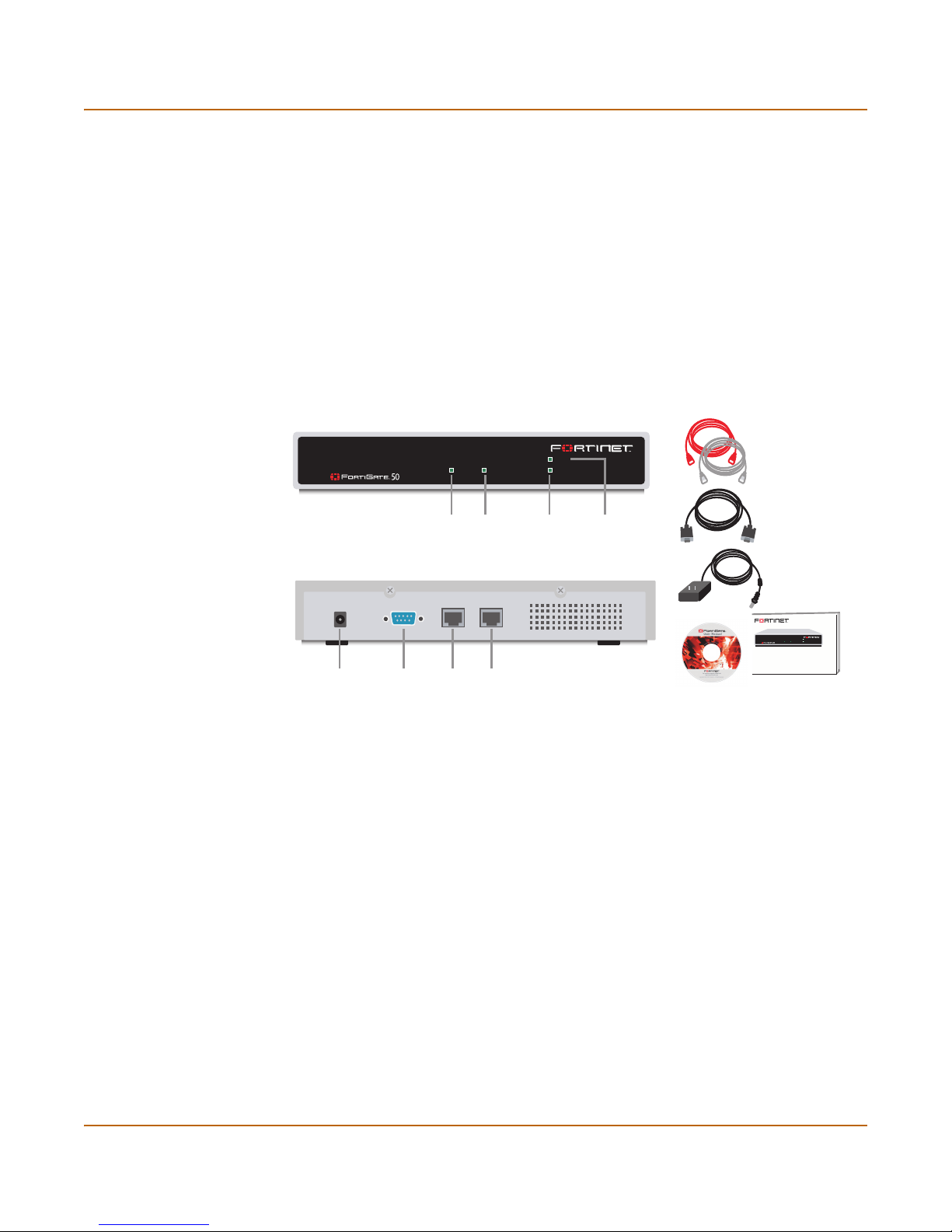
Package contents
The FortiGate-50 package contains the following items:
• the FortiGate-50 Antivirus Firewall
• one orange cross-over ethernet cable
• one gray regular ethernet cable
• one null-modem cable
• FortiGate-50 QuickStart Guide
• A CD containing the FortiGate user documentation
• one AC adapter
Figure 1: FortiGate-50 package contents
Front
Ethernet Cables:
INTERNAL EXTERNAL
POWER
STATUS
Orange - Crossover
Grey - Straight-through
Mounting
Null-Modem Cable
(RS-232)
AC Adapter
FortiGate-50
POWER
INTERNAL EXTERNAL
STATUS
QuickStart Guide
Copyright 2003 Fortinet Incorporated. All rights reserved.
Trademarks
Products mentioned in this document are trademarks.
Documentation
Power
Connection
ConsoleDC+5V 3A
RS-232 Serial
Connection
Internal
Interface
External
External
Interface
External
Interface
Back
Internal
Internal
Interface
Status
LED
Power
LED
USER MANUAL
The FortiGate-50 unit can be installed on any stable surface. Make sure that the
appliance has at least 1.5 in. (3.75 cm) of clearance on each side to allow for
adequate air flow and cooling.
Dimensions
• 8.63 x 6.13 x 1.38 in. (21.9 x 15.6 x 3.5 cm)
Weight
• 1.5 lb. (0.68 kg)
Power requirements
• DC input voltage: 5 V
• DC input current: 3 A
18 Fortinet Inc.
Page 19

Getting started Powering on
Environmental specifications
• Operating temperature: 32 to 104°F (0 to 40°C)
• Storage temperature: -13 to 158°F (-25 to 70°C)
• Humidity: 5 to 95% non-condensing
Powering on
To power on the FortiGate-50 unit:
1 Connect the AC adapter to the power connection at the back of the FortiGate-50 unit.
2 Connect the AC adapter to a power outlet.
The FortiGate-50 unit starts up. The Power and Status lights light. The Status light
flashes while the FortiGate-50 unit is starting up and remains lit when the system is up
and running.
Table 1: FortiGate-50 LED indicators
LED State Description
Power Green The FortiGate unit is powered on.
Off The FortiGate unit is powered off.
Status Flashing
Internal
External
(Front)
Internal
External (Back)
Green
Green The FortiGate unit is running normally.
Off The FortiGate unit is powered off.
Green The correct cable is in use, and the connected equipment has
Flashing
Green
Off No link established.
Green The correct cable is in use, and the connected equipment has
Flashing
Amber
Off No link established.
The FortiGate unit is starting up.
power.
Network activity at this interface.
power.
Network activity at this interface.
FortiGate-50R Installation and Configuration Guide 19
Page 20

Connecting to the web-based manager Getting started
Connecting to the web-based manager
Use the following procedure to connect to the web-based manager for the first time.
Configuration changes made with the web-based manager are effective immediately
without the need to reset the firewall or interrupt service.
To connect to the web-based manager, you need:
• a computer with an ethernet connection,
• Internet Explorer version 4.0 or higher,
• a crossover cable or an ethernet hub and two ethernet cables.
Note: You can use the web-based manager with recent versions of most popular web browsers.
The web-based manager is fully supported for Internet Explorer version 4.0 or higher.
Connecting to the web-based manager
1 Set the IP address of the computer with an ethernet connection to the static IP
address 192.168.1.2 and a netmask of 255.255.255.0.
You can also configure the management computer to obtain an IP address
automatically using DHCP. The FortiGate DHCP server assigns the management
computer an IP address in the range 192.168.1.1 to 192.168.1.254.
2 Using the crossover cable or the ethernet hub and cables, connect the Internal
interface of the FortiGate unit to the computer ethernet connection.
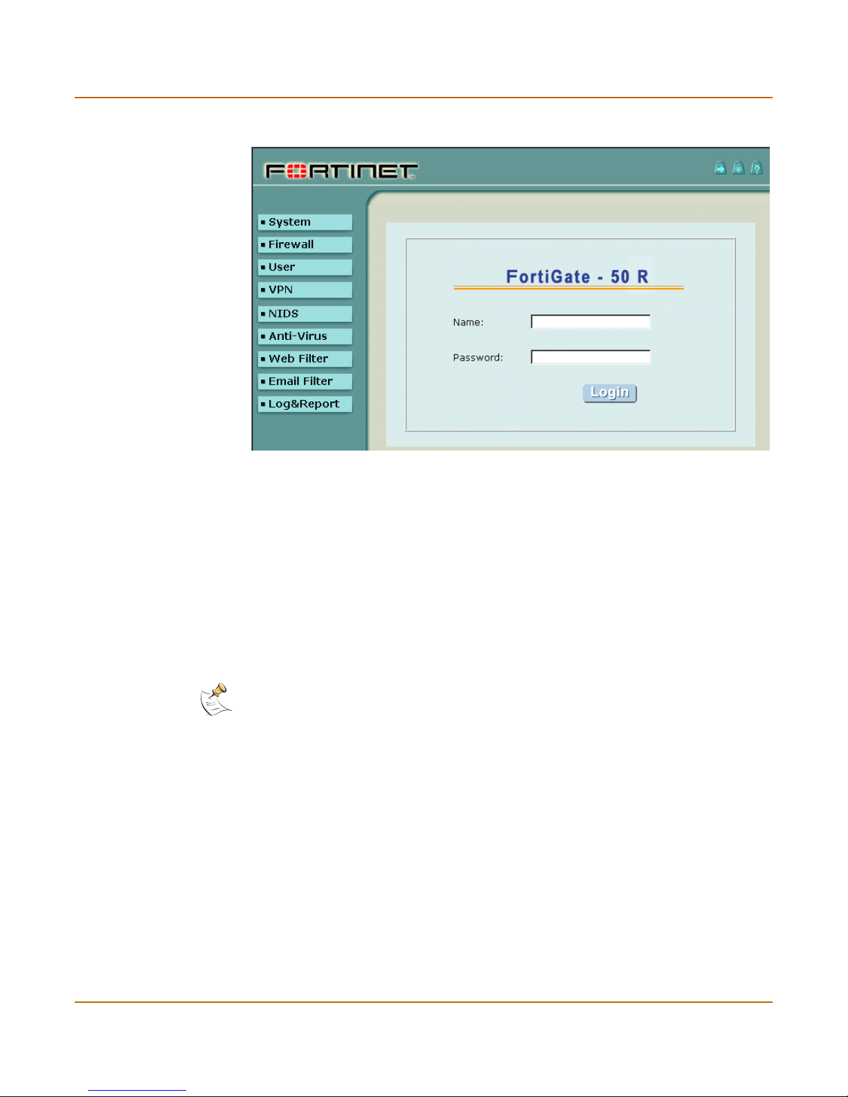
3 Start Internet Explorer and browse to the address https://192.168.1.99.
The FortiGate login is displayed.
4 Type admin in the Name field and select Login.
The Register Now window is displayed. Use the information on this window to register
your FortiGate unit so that Fortinet can contact you for firmware updates. You must
also register to receive updates to the FortiGate virus and attack definitions.
20 Fortinet Inc.
Page 21
Getting started Connecting to the command line interface (CLI)
Figure 2: FortiGate login
Connecting to the command line interface (CLI)
As an alternative to the web-based manager, you can install and configure the
FortiGate unit using the CLI. Configuration changes made with the CLI are effective
immediately without the need to reset the firewall or interrupt service.
To connect to the FortiGate CLI, you need:
• a computer with an available communications port,
• the null modem cable included in your FortiGate package,
• terminal emulation software such as HyperTerminal for Windows.
Note: The following procedure describes how to connect to the CLI using Windows
HyperTerminal software. You can use any terminal emulation program.
To connect to the CLI:
1 Connect the null modem cable to the communications port of your computer and to
the FortiGate Console port.
2 Make sure that the FortiGate unit is powered on.
3 Start HyperTerminal, enter a name for the connection, and select OK.
4 Configure HyperTerminal to connect directly to the communications port on the
computer to which you have connected the null modem cable and select OK.
5 Select the following port settings and select OK.
FortiGate-50R Installation and Configuration Guide 21
Page 22

Factory default FortiGate configuration settings Getting started
Bits per second 9600
Data bits 8
Parity None
Stop bits 1
Flow control None
6 Press Enter to connect to the FortiGate CLI.
The following prompt appears:
FortiGate-50 login:
7 Type admin and press Enter twice.
The following prompt appears:
Type ? for a list of commands.
For information on how to use the CLI, see the FortiGate CLI Reference Guide.
Factory default FortiGate configuration settings
The FortiGate unit is shipped with a factory default configuration. This default
configuration allows you to connect to and use the FortiGate web-based manager to
configure the FortiGate unit onto your network. To configure the FortiGate unit onto
your network you add an administrator password, change network interface IP
addresses, add DNS server IP addresses, and configuring routing if required.
If you are planning on operating the FortiGate unit in Transparent mode, you can
switch to transparent mode from the factory default configuration and then configure
the FortiGate unit onto your network in Transparent mode.
Once the network configuration is complete, you can perform additional configuration
tasks such as setting system time, configuring virus and attack definition updates, and
registering the FortiGate unit.
The factory default firewall configuration includes a single network address translation
(NAT) policy that allows users on your internal network to connect to the external
network, and stops users on the external network from connecting to the internal
network. You can add more policies to provide more control of the network traffic
passing through the FortiGate unit.
The factory default content profiles can be used to quickly apply different levels of
antivirus protection, web content filtering, and email filtering to the network traffic
controlled by firewall policies.
• Factory Default DHCP configuration
• Factory default NAT/Route mode network configuration
• Factory default Transparent mode network configuration
• Factory default firewall configuration
• Factory default content profiles
22 Fortinet Inc.
Page 23

Getting started Factory default FortiGate configuration settings
Factory Default DHCP configuration
When the FortiGate unit is first powered on, the external interface is configured to
receive its IP address by connecting to a DHCP server. If your ISP provides IP
addresses using DHCP, no other configuration is required for this interface.
The FortiGate unit can also function as a DHCP server for your internal network. You
can configure the TCP/IP settings of the computers on your internal network to obtain
an IP address automatically from the FortiGate unit DHCP server. For more
information about the FortiGate DHCP server, see “Providing DHCP services to your
internal network” on page 99.
Table 2: FortiGate DHCP Server default configuration
Enable DHCP ;
Starting IP 192.168.1.1
Ending IP 192.168.1.254
Netmask 255.255.255.0
Lease Duration 604800 seconds
Default Route 192.168.1.99
Exclusion Range 192.168.1.99 - 192.168.1.99
Factory default NAT/Route mode network configuration
When the FortiGate unit is first powered on, it is running in NAT/Route mode and has
the basic network configuration listed in Ta bl e 3. This configuration allows you to
connect to the FortiGate unit web-based manager and establish the configuration
required to connect the FortiGate unit to your network. In Table 3 HTTPS
management access means you can connect to the web-based manager using this
interface. Ping management access means this interface responds to ping requests.
Table 3: Factory default NAT/Route mode network configuration
Administrator
account
Internal interface
External interface
User name: admin
Password: (none)
IP: 192.168.1.99
Netmask: 255.255.255.0
Management Access: HTTPS, Ping
Addressing Mode: DHCP
Management Access: Ping
FortiGate-50R Installation and Configuration Guide 23
Page 24

Factory default FortiGate configuration settings Getting started
Factory default Transparent mode network configuration
If you switch the FortiGate unit to Transparent mode, it has the default network
configuration listed in Ta bl e 4 .
Table 4: Factory default Transparent mode network configuration
Administrator
account
Management IP
DNS
Management access
User name: admin
Password: (none)
IP: 10.10.10.1
Netmask: 255.255.255.0
Primary DNS Server: 207.194.200.1
Secondary DNS Server: 207.194.200.129
Internal HTTPS, Ping
External Ping
Factory default firewall configuration
The factory default firewall configuration is the same in NAT/Route and Transparent
mode.
Table 5: Factory default firewall configuration
Internal
Address
External
Address
Recurring
Schedule
Firewall
Policy
Internal_All
External_All
Always The schedule is valid at all times. This means that
Int->Ext Firewall policy for connections from the internal
Source Internal_All The policy source address. Internal_All means that
Destination External_All The policy destination address. External_All means
Schedule Always The policy schedule. Always means that the policy
Service ANY The policy service. ANY means that this policy
Action ACCEPT The policy action. ACCEPT means that the policy
; NAT NAT is selected for the NAT/Route mode default
IP: 0.0.0.0 Represents all of the IP addresses on the internal
Mask: 0.0.0.0
IP: 0.0.0.0 Represents all of the IP addresses on the external
Mask: 0.0.0.0
network.
network.
the firewall policy is valid at all times.
network to the external network.
the policy accepts connections from any internal IP
address.
that the policy accepts connections with a
destination address to any IP address on the
external network.
is valid at any time.
processes connections for all services.
allows connections.
policy so that the policy applies network address
translation to the traffic processed by the policy.
NAT is not available for Transparent mode policies.
24 Fortinet Inc.
Page 25

Getting started Factory default FortiGate configuration settings
Table 5: Factory default firewall configuration (Continued)
Traffic Shaping Traffic shaping is not selected. The policy does not
Authentication Authentication is not selected. Users do not have to
; Antivirus & Web Filter Antivirus & Web Filter is selected.
Content
Profile
Log Traffic Log Traffic is not selected. This policy does not
Factory default content profiles
You can use content profiles to apply different protection settings for content traffic
controlled by firewall policies. You can use content profiles for:
• Antivirus protection of HTTP, FTP, IMAP, POP3, and SMTP network traffic
• Web content filtering for HTTP network traffic
• Email filtering for IMAP and POP3 network traffic
• Oversized file and email blocking for HTTP, FTP, POP3, SMTP, and IMAP network
traffic
• Passing fragmented emails in IMAP, POP3, and SMTP email traffic
Using content profiles you can build up protection configurations that can be easily
applied to different types of Firewall policies. This allows you to customize different
types and different levels of protection for different firewall policies.
For example, while traffic between internal and external addresses might need strict
protection, traffic between trusted internal addresses might need moderate protection.
You can configure policies for different traffic services to use the same or different
content profiles.
apply traffic shaping to the traffic controlled by the
policy. You can select this option to control the
maximum or minimum amount of bandwidth
available to traffic processed by the policy.
authenticate with the firewall before connecting to
their destination address. You can configure user
groups and select this option to require users to
authenticate with the firewall before they can
connect through the firewall.
Scan The scan content profile is selected. The policy
scans all HTTP, FTP, SMTP, POP3, and IMAP
traffic for viruses. See “Scan content profile” on
page 26 for more information about the scan
content profile. You can select one of the other
content profiles to apply different levels of content
protection to traffic processed by this policy.
record messages to the traffic log for the traffic
processed by this policy. You can configure
FortiGate logging and select Log Traffic to record all
connections through the firewall that are accepted
by this policy.
Content profiles can be added to NAT/Route mode and Transparent mode policies.
FortiGate-50R Installation and Configuration Guide 25
Page 26

Factory default FortiGate configuration settings Getting started
Strict content profile
Use the strict content profile to apply maximum content protection to HTTP, FTP,
IMAP, POP3, and SMTP content traffic. You would not use the strict content profile
under normal circumstances, but it is available if you are having extreme problems
with viruses and require maximum content screening protection.
Table 6: Strict content profile
Options HTTP FTP IMAP POP3 SMTP
Antivirus Scan ;;;;;
File Block ;;;;;
Web URL Block ;
Web Content Block ;
Web Script Filter ;
Web Exempt List ;
Email Block List ;;
Email Exempt List ;;
Email Content Block ;;
Oversized File/Email Block block block block block block
Pass Fragmented Emails
Scan content profile
Use the scan content profile to apply antivirus scanning to HTTP, FTP, IMAP, POP3,
and SMTP content traffic.
Table 7: Scan content profile
Options HTTP FTP IMAP POP3 SMTP
Antivirus Scan ;;;;;
File Block
Web URL Block
Web Content Block
Web Script Filter
Web Exempt List
Email Block List
Email Exempt List
Email Content Block
Oversized File/Email Block pass pass pass pass pass
Pass Fragmented Emails
26 Fortinet Inc.
Page 27

Getting started Factory default FortiGate configuration settings
Web content profile
Use the web content profile to apply antivirus scanning and Web content blocking to
HTTP content traffic. You can add this content profile to firewall policies that control
HTTP traffic.
Table 8: Web content profile
Options HTTP FTP IMAP POP3 SMTP
Antivirus Scan ;
File Block
Web URL Block ;
Web Content Block ;
Web Script Filter
Web Exempt List
Email Block List
Email Exempt List
Email Content Block
Oversized File/Email Block pass pass pass pass pass
Pass Fragmented Emails
Unfiltered content profile
Use the unfiltered content profile if you do not want to apply any content protection to
content traffic. You can add this content profile to firewall policies for connections
between highly trusted or highly secure networks where content does not need to be
protected.
Table 9: Unfiltered content profile
Options HTTP FTP IMAP POP3 SMTP
Antivirus Scan
File Block
Web URL Block
Web Content Block
Web Script Filter
Web Exempt List ;
Email Block List
Email Exempt List ;;
Email Content Block
Oversized File/Email Block pass pass pass pass pass
Pass Fragmented Emails ;;;
FortiGate-50R Installation and Configuration Guide 27
Page 28
Planning your FortiGate configuration Getting started
Planning your FortiGate configuration
Before beginning to configure the FortiGate unit, you need to plan how to integrate the
unit into your network. Among other things, you have to decide whether or not the unit
will be visible to the network, which firewall functions it will provide, and how it will
control the traffic flowing between its interfaces.
Your configuration plan is dependent upon the operating mode that you select. The
FortiGate unit can be configured in either of two modes: NAT/Route mode (the default)
or Transparent mode.
NAT/Route mode
In NAT/Route mode, the unit is visible to the network. Like a router, all of its interfaces
are on different subnets. The following interfaces are available in NAT/Route mode:
• External is the interface to the external network (usually the Internet).
• Internal is the interface to the internal network.
You can add security policies to control whether communications through the
FortiGate unit operate in NAT mode or in route mode. Security policies control the flow
of traffic based on each packet’s source address, destination address and service. In
NAT mode, the FortiGate performs network address translation before the packet is
sent to the destination network. In route mode, no translation takes place.
By default, the FortiGate unit has a NAT mode security policy that allows users on the
internal network to securely download content from the external network. No other
traffic is possible until you have configured more security policies.
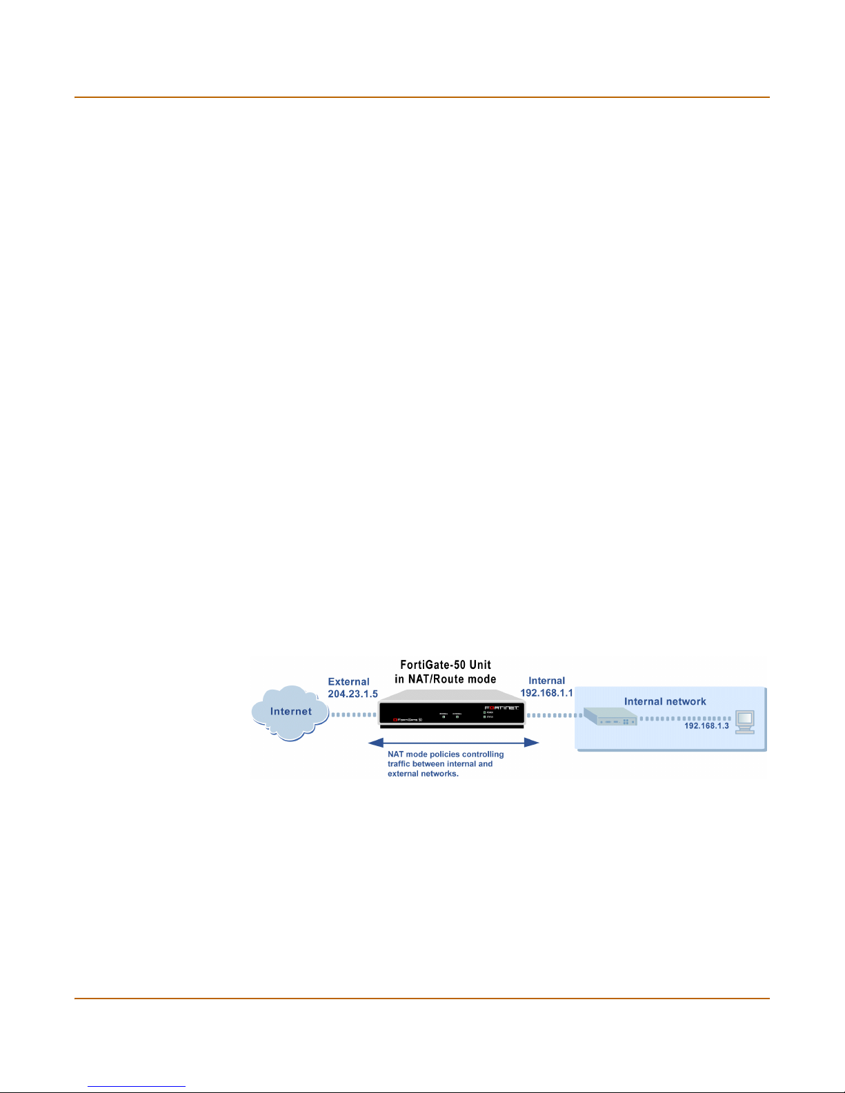
You would typically use NAT/Route mode when the FortiGate unit is used as a
gateway between private and public networks. In this configuration, you would create
NAT mode policies to control traffic flowing between the internal, private network and
the external, public network (usually the Internet).
Figure 3: Example NAT/Route mode network configuration
Transparent mode
In Transparent mode, the FortiGate unit is invisible to the network. Similar to a
network bridge, all of FortiGate interfaces must be on the same subnet. You only have
to configure a management IP address so that you can make configuration changes.
The management IP address is also used for antivirus and attack definition updates.
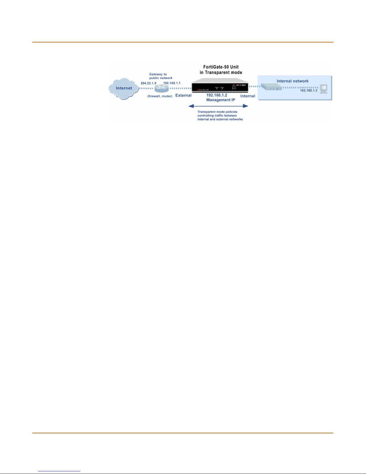
You would typically use the FortiGate unit in Transparent mode on a private network
behind an existing firewall or behind a router. The FortiGate unit performs firewalling
as well as antivirus and content scanning but not VPN.
28 Fortinet Inc.
Page 29
Getting started Planning your FortiGate configuration
Figure 4: Example Transparent mode network configuration
Configuration options
Once you have selected Transparent or NAT/Route mode operation, you can
complete your configuration plan, and begin configuring the FortiGate unit.
You can use the web-based manager setup wizard or the command line interface
(CLI) for the basic configuration of the FortiGate unit.
Setup Wizard
If you are configuring the FortiGate unit to operate in NAT/Route mode (the default),
the Setup Wizard prompts you to add the administration password and the internal
interface address. The Setup Wizard also prompts you to choose either a manual
(static) or a dynamic (DHCP or PPPoE) address for the external interface. Using the
wizard, you can also add DNS server IP addresses and a default route for the external
interface.
In NAT/Route mode you can also change the configuration of the FortiGate DHCP
server to supply IP addresses for the computers on your internal network. You can
also configure the FortiGate to allow Internet access to your internal Web, FTP, or
email servers.
If you are configuring the FortiGate unit to operate in Transparent mode, you can
switch to Transparent mode from the web-based manager and then use the Setup
Wizard to add the administration password, the management IP address and
gateway, and the DNS server addresses.
CLI
If you are configuring the FortiGate unit to operate in NAT/Route mode, you can add
the administration password and the Internal interface address. You can also use the
CLI to configure the external interface for either a manual (static) or a dynamic (DHCP
or PPPoE) address. Using the CLI, you can also add DNS server IP addresses and a
default route for the external interface.
In NAT/Route mode you can also change the configuration of the FortiGate DHCP
server to supply IP addresses for the computers on your internal network.
If you are configuring the FortiGate unit to operate in Transparent mode, you can use
the CLI to switch to Transparent mode, Then you can add the administration
password, the management IP address and gateway, and the DNS server addresses.
FortiGate-50R Installation and Configuration Guide 29
Page 30

FortiGate model maximum values matrix Getting started
FortiGate model maximum values matrix
Table 10: FortiGate maximum values matrix
FortiGate model
50 60 100 200 300 400 500 1000 2000 3000 3600
Policy 200 500 1000 2000 5000 5000 20000 50000 50000 50000 50000
Address 500 500 500 500 3000 3000 6000 10000 10000 10000 10000
Address group 500 500 500 500 500 500 500 500 500 500 500
Service 500 500 500 500 500 500 500 500 500 500 500
Service group 500 500 500 500 500 500 500 500 500 500 500
Recurring schedule 256 256 256 256 256 256 256 256 256 256 256
Onetime schedule 256 256 256 256 256 256 256 256 256 256 256
User 20 500 1000 1000 1000 1000 1000 1000 1000 1000 1000
User group 100 100 100 100 100 100 100 100 100 100 100
Group members 300 300 300 300 300 300 300 300 300 300 300
Virtual IPs 500 500 500 500 500 500 500 500 500 500 500
IP/MAC binding 50 100 1000 1000 2000 2000 2000 5000 5000 5000 5000
Route 500 500 500 500 500 500 500 500 500 500 500
Policy route gateway 500 500 500 500 500 500 500 500 500 500 500
Admin user 500 500 500 500 500 500 500 500 500 500 500
IPsec Phase 1 20 50 80 200 1500 1500 3000 5000 5000 5000 5000
VPN concentrator 500 500 500 500 500 500 500 500 500 500 500
VLAN subinterface N/A N/A N/A N/A N/A 1024* 1024* 2048* 2048* 8192* 8192*
Zone N/A N/A N/A N/A N/A 100 100 200 200 300 500
IP pool 50 50 50 50 50 50 50 50 50 50 50
RADIUS server 66666666666
File pattern 56 56 56 56 56 56 56 56 56 56 56
PPTP user 500 500 500 500 500 500 500 500 500 500 500
L2TP user 500 500 500 500 500 500 500 500 500 500 500
URL block no limit no limit no limit no limit no limit no limit no limit no limit no limit no limit no limit
Content block no limit no limit no limit no limit no limit no limit no limit no limit no limit no limit no limit
Exempt URL no limit no limit no limit no limit no limit no limit no limit no limit no limit no limit no limit
30 Fortinet Inc.
Page 31

Getting started Next steps
Next steps
Now that your FortiGate unit is operating, you can proceed to configure it to connect to
networks:
• If you are going to operate the FortiGate unit in NAT/Route mode, go to
“NAT/Route mode installation” on page 33.
• If you are going to operate the FortiGate unit in Transparent mode, go to
“Transparent mode installation” on page 41.
FortiGate-50R Installation and Configuration Guide 31
Page 32

Next steps Getting started
32 Fortinet Inc.
Page 33

FortiGate-50R Installation and Configuration Guide Version 2.50 MR2
NAT/Route mode installation
This chapter describes how to install the FortiGate unit in NAT/Route mode. To install
the FortiGate unit in Transparent mode, see “Transparent mode installation” on
page 41.
This chapter describes:
• Installing the FortiGate unit using the default configuration
• Preparing to configure NAT/Route mode
• Using the setup wizard
• Using the command line interface
• Connecting the FortiGate unit to your networks
• Configuring your networks
• Completing the configuration
Installing the FortiGate unit using the default configuration
Depending on your requirements, you may be able to deploy the FortiGate unit
without changing its factory default configuration. If the factory default settings in
Ta bl e 11 are compatible with your requirements, all you need to do is configure your
internal network and then connect the FortiGate unit.
Table 11: FortiGate unit factory default configuration
Operating Mode NAT/Route mode.
Firewall Policy One NAT mode policy that allows users on the internal network to access
External
interface
DHCP Server
on internal
network
any Internet service. No other traffic is allowed. All web and email traffic
is scanned for viruses.
The External interface receives its IP address by DHCP from your
Internet Service Provider (ISP).
The FortiGate unit functions as a DHCP server for your internal network.
If you configure the computers on your internal network to obtain an IP
address automatically using DHCP, the FortiGate unit automatically sets
the IP addresses of the computers in this range:
Starting IP: 192.168.1.1
Ending IP: 192.168.1.254
One IP address is reserved for the FortiGate internal interface:
192.168.1.99.
FortiGate-50R Installation and Configuration Guide 33
Page 34

Preparing to configure NAT/Route mode NAT/Route mode installation
To use the factory default configuration, follow these steps to install the FortiGate unit:
1 Configure the TCP/IP settings of the computers on your internal network to obtain an
IP address automatically using DHCP. Refer to your computer documentation for
assistance.
2 Complete the procedure in the section “Connecting the FortiGate unit to your
networks” on page 37.
Changing the default configuration
You can use the procedures in this chapter to change the default configuration. For
example, if your ISP assigns IP addresses using PPPoE instead of DHCP, you only
need to change the configuration of the external interface. Use the information in the
rest of this chapter to change the default configuration as required.
Preparing to configure NAT/Route mode
Use Tab le 12 to gather the information that you need to customize NAT/Route mode
settings.
Table 12: NAT/Route mode settings
Administrator password:
Internal
interface
External
interface
Internal servers
If you provide access from the Internet to a web server, mail server, IMAP
server, or FTP server installed on an internal network, add the IP
addresses of the servers here.
IP: _____._____._____._____
Netmask: _____._____._____._____
IP: _____._____._____._____
Netmask: _____._____._____._____
Default Gateway: _____._____._____._____
Primary DNS Server: _____._____._____._____
Secondary DNS Server: _____._____._____._____
Web Server: _____._____._____._____
SMTP Server: _____._____._____._____
POP3 Server: _____._____._____._____
IMAP Server: _____._____._____._____
FTP Server: _____._____._____._____
34 Fortinet Inc.
Page 35

NAT/Route mode installation Using the setup wizard
Advanced NAT/Route mode settings
Use Tab le 13 to gather the information that you need to customize advanced
FortiGate NAT/Route mode settings.
Table 13: Advanced FortiGate NAT/Route mode settings
Starting IP: _____._____._____._____
Ending IP: _____._____._____._____
Netmask: _____._____._____._____
DHCP server
The FortiGate unit contains a DHCP server that you can configure to
automatically set the addresses of the computers on your internal network.
Default Route: _____._____._____._____
DNS IP: _____._____._____._____
Using the setup wizard
From the web-based manager, you can use the setup wizard to create the initial
configuration of your FortiGate unit. To connect to the web-based manager, see
“Connecting to the web-based manager” on page 20.
Starting the setup wizard
1 Select Easy Setup Wizard (the middle button in the upper-right corner of the
web-based manager).
2 Use the information that you gathered in Table 12 on page 34 to fill in the wizard fields.
Select the Next button to step through the wizard pages.
3 Confirm your configuration settings and then select Finish and Close.
Note: If you use the setup wizard to configure internal server settings, the FortiGate unit adds
port forwarding virtual IPs and firewall policies for each server. For each server located on your
internal network the FortiGate unit adds an Ext->Int policy.
Reconnecting to the web-based manager
If you used the setup wizard to change the IP address of the internal interface, you
must reconnect to the web-based manager using a new IP address. Browse to https://
followed by the new IP address of the internal interface. Otherwise, you can reconnect
to the web-based manager by browsing to https://192.168.1.99.
You have now completed the initial configuration of your FortiGate unit, and you can
proceed to “Connecting the FortiGate unit to your networks” on page 37.
FortiGate-50R Installation and Configuration Guide 35
Page 36

Using the command line interface NAT/Route mode installation
Using the command line interface
As an alternative to using the setup wizard, you can configure the FortiGate unit using
the command line interface (CLI). To connect to the CLI, see “Connecting to the
command line interface (CLI)” on page 21.
Configuring the FortiGate unit to operate in NAT/Route mode
Use the information that you gathered in Table 12 on page 34 to complete the
following procedures.
Configuring NAT/Route mode IP addresses
1 Log into the CLI if you are not already logged in.
2 Set the IP address and netmask of the internal interface to the internal IP address and
netmask that you recorded in Table 12 on page 34. Enter:
set system interface internal mode static ip <IP address>
<netmask>
Example
set system interface internal mode static ip 192.168.1.1
255.255.255.0
3 Set the IP address and netmask of the external interface to the external IP address
and netmask that you recorded in Table 12 on page 34.
To set the manual IP address and netmask, enter:
set system interface external static ip <IP address> <netmask>
Example
set system interface external mode
255.255.255.0
To set the external interface to use DHCP, enter:
set system interface external mode dhcp connection enable
To set the external interface to use PPPoE, enter:
set system interface external mode pppoe
password
Example
set system interface external mode pppoe username
user@domain.com password mypass connection enable
4 Confirm that the addresses are correct. Enter:
get system interface
The CLI lists the IP address, netmask and other settings for each of the FortiGate
interfaces.
5 Set the primary DNS server IP addresses. Enter
set system dns primary <IP address>
Example
set system dns primary 293.44.75.21
6 Optionally, set the secondary DNS server IP addresses. Enter
set system dns secondary <IP address>
Example
set system dns secondary 293.44.75.22
<password>
connection
static
enable
ip 204.23.1.5
username
<user name>
36 Fortinet Inc.
Page 37

NAT/Route mode installation Connecting the FortiGate unit to your networks
7 Set the default route to the Default Gateway IP address (not required for DHCP and
PPPoE).
set system route number <route_no> dst 0.0.0.0 0.0.0.0 gw1
<gateway_ip>
Example
set system route number 0 dst 0.0.0.0 0.0.0.0 gw1 204.23.1.2
Connecting the FortiGate unit to your networks
When you have completed the initial configuration, you can connect the FortiGate unit
between your internal network and the Internet.
There are two 10/100 BaseTX connectors on the FortiGate-50:
• Internal for connecting to your internal network,
• External for connecting to the Internet.
To connect the FortiGate-50 unit:
1 Connect the Internal interface to the hub or switch connected to your internal network.
2 Connect the External interface to the Internet.
Connect to the public switch or router provided by your Internet Service Provider. If
you are a DSL or cable subscriber, connect the External interface to the internal or
LAN connection of your DSL or cable modem.
Figure 5: FortiGate-50 network connections
FortiGate-50R Installation and Configuration Guide 37
Page 38

Configuring your networks NAT/Route mode installation
Configuring your networks
If you are operating the FortiGate unit in NAT/Route mode, your internal network must
be configured to route all Internet traffic to the FortiGate internal interface. Change the
default gateway address of all computers and routers connected directly to your
internal network to the IP address of the FortiGate internal interface. For the external
network, route all packets to the FortiGate external interface.
If you are using the FortiGate unit as the DHCP server for your internal network,
configure the computers on your internal network for DHCP.
Make sure that the connected FortiGate unit is functioning properly by connecting to
the Internet from a computer on your internal network. You should be able to connect
to any Internet address.
Completing the configuration
Use the information in this section to complete the initial configuration of the FortiGate
unit.
Setting the date and time
For effective scheduling and logging, the FortiGate system date and time should be
accurate. You can either manually set the system date and time or you can configure
the FortiGate unit to automatically keep its time correct by synchronizing with a
Network Time Protocol (NTP) server.
To set the FortiGate system date and time, see “Setting system date and time” on
page 101.
Changing antivirus protection
By default, the FortiGate unit scans all web and email content for viruses. You can use
the following procedure to change the antivirus configuration. To change the antivirus
configuration:
1 Select Edit to edit this policy.
2 For Anti-Virus & Web Filter you can select a different Content Profile.
See “Factory default content profiles” on page 25 for descriptions of the default
content profiles.
3 Select OK to save your changes.
You can also add you own content profiles. See “Adding a content profile” on
page 141.
Registering your FortiGate
After purchasing and installing a new FortiGate unit, you can register the unit by going
to System > Update > Support, or using a web browser to connect to
http://support.fortinet.com and selecting Product Registration.
38 Fortinet Inc.
Page 39

NAT/Route mode installation Completing the configuration
Registration consists of entering your contact information and the serial numbers of
the FortiGate units you or your organization have purchased. Registration is quick and
easy. You can register multiple FortiGate units in a single session without re-entering
your contact information.
For more information about registration, see “Registering FortiGate units” on page 81.
Configuring virus and attack definition updates
You can go to System > Update to configure the FortiGate unit to automatically check
to see if new versions of the virus definitions and attack definitions are available. If it
finds new versions, the FortiGate unit automatically downloads and installs the
updated definitions.
The FortiGate unit uses HTTPS on port 8890 to check for updates. The FortiGate
external interface must have a path to the FortiResponse Distribution Network (FDN)
using port 8890.
To configure automatic virus and attack updates, see “Updating antivirus and attack
definitions” on page 71.
FortiGate-50R Installation and Configuration Guide 39
Page 40

Completing the configuration NAT/Route mode installation
40 Fortinet Inc.
Page 41

FortiGate-50R Installation and Configuration Guide Version 2.50 MR2
Transparent mode installation
This chapter describes how to install your FortiGate unit in Transparent mode. If you
want to install the FortiGate unit in NAT/Route mode, see “NAT/Route mode
installation” on page 33.
This chapter describes:
• Preparing to configure Transparent mode
• Using the setup wizard
• Using the command line interface
• Connecting the FortiGate unit to your networks
• Completing the configuration
• Transparent mode configuration examples
Preparing to configure Transparent mode
Use Ta bl e 1 4 to gather the information that you need to customize Transparent mode
settings.
Table 14: Transparent mode settings
Administrator Password:
IP: _____._____._____._____
Netmask: _____._____._____._____
Management IP
The management IP address and netmask must be valid for the network
from which you will manage the FortiGate unit. Add a default gateway if the
FortiGate unit must connect to a router to reach the management
computer.
DNS Settings
Default Gateway: _____._____._____._____
Primary DNS Server: _____._____._____._____
Secondary DNS Server: _____._____._____._____
FortiGate-50R Installation and Configuration Guide 41
Page 42

Using the setup wizard Transparent mode installation
Using the setup wizard
From the web-based manager, you can use the setup wizard to create the initial
configuration of your FortiGate unit. To connect to the web-based manager, see
“Connecting to the web-based manager” on page 20.
Changing to Transparent mode
The first time that you connect to the FortiGate unit, it is configured to run in
NAT/Route mode. To switch to Transparent mode using the web-based manager:
1 Go to System > Status.
2 Select Change to Transparent Mode.
3 Select Transparent in the Operation Mode list.
4 Select OK.
The FortiGate unit changes to Transparent mode.
To reconnect to the web-based manager, change the IP address of your management
computer to 10.10.10.2. Connect to the internal or DMZ interface and browse to
https:// followed by the Transparent mode management IP address. The default
FortiGate Transparent mode management IP address is 10.10.10.1.
Starting the setup wizard
1 Select Easy Setup Wizard (the middle button in upper-right corner of the web-based
manager).
2 Use the information that you gathered in Table 14 on page 41 to fill in the wizard fields.
Select the Next button to step through the wizard pages.
3 Confirm your configuration settings and then select Finish and Close.
Reconnecting to the web-based manager
If you changed the IP address of the management interface while you were using the
setup wizard, you must reconnect to the web-based manager using the new IP
address. Browse to https:// followed by the new IP address of the management
interface. Otherwise, you can reconnect to the web-based manager by browsing to
https://10.10.10.1. If you connect to the management interface through a router, make
sure that you have added a default gateway for that router to the management IP
default gateway field.
Using the command line interface
As an alternative to the setup wizard, you can configure the FortiGate unit using the
command line interface (CLI). To connect to the CLI, see “Connecting to the command
line interface (CLI)” on page 21. Use the information that you gathered in Table 14 on
page 41 to complete the following procedures.
42 Fortinet Inc.
Page 43

Transparent mode installation Using the command line interface
Changing to Transparent mode
1 Log into the CLI if you are not already logged in.
2 Switch to Transparent mode. Enter:
set system opmode transparent
After a few seconds, the login prompt appears.
3 Type admin and press Enter.
The following prompt appears:
Type ? for a list of commands.
4 Confirm that the FortiGate unit has switched to Transparent mode. Enter:
get system status
The CLI displays the status of the FortiGate unit. The last line shows the current
operation mode.
Operation mode: Transparent
Configuring the Transparent mode management IP address
1 Log into the CLI if you are not already logged in.
2 Set the management IP address and netmask to the IP address and netmask that you
recorded in Table 14 on page 41. Enter:
set system management ip <IP address> <netmask>
Example
set system management ip 10.10.10.2 255.255.255.0
3 Confirm that the address is correct. Enter:
get system management
The CLI lists the management IP address and netmask.
Configure the Transparent mode default gateway
1 Log into the CLI if you are not already logged in.
2 Set the default route to the default gateway that you recorded in Table 14 on page 41.
Enter:
set system route number <number> gateway <IP address>
Example
set system route
You have now completed the initial configuration of the FortiGate unit.
number 1 gw1
204.23.1.2
FortiGate-50R Installation and Configuration Guide 43
Page 44

Connecting the FortiGate unit to your networks Transparent mode installation
Connecting the FortiGate unit to your networks
When you have completed the initial configuration, you can connect the FortiGate unit
between your internal network and the Internet.
There are two 10/100 BaseTX connectors on the FortiGate-50 unit:
• Internal for connecting to your internal network,
• External for connecting to the Internet.
To connect the FortiGate unit:
1 Connect the Internal interface to the hub or switch connected to your internal network.
2 Connect the External interface to the Internet.
Connect to the public switch or router provided by your Internet Service Provider.
Figure 6: FortiGate-50 network connections
In Transparent mode, the FortiGate unit does not change the layer 3 topology. This
means that all of its interfaces are on the same IP subnet and that it appears to other
devices as a bridge. Typically, the FortiGate unit would be deployed in Transparent
mode when it is intended to provide antivirus and content scanning behind an existing
firewall solution.
A FortiGate unit in Transparent mode can also perform firewalling. Even though it
takes no part in the layer 3 topology, it can examine layer 3 header information and
make decisions on whether to block or pass traffic.
44 Fortinet Inc.
Page 45

Transparent mode installation Completing the configuration
Completing the configuration
Use the information in this section to complete the initial configuration of the FortiGate
unit.
Setting the date and time
For effective scheduling and logging, the FortiGate system date and time should be
accurate. You can either manually set the date and time or you can configure the
FortiGate unit to automatically keep its date and time correct by synchronizing with a
Network Time Protocol (NTP) server.
To set the FortiGate system date and time, see “Setting system date and time” on
page 101.
Enabling antivirus protection
To enable antivirus protection to protect users on your internal network from
downloading a virus from the Internet:
1 Go to Firewall > Policy > Int->Ext.
2 Select Edit to edit this policy.
3 Select Anti-Virus & Web filter to enable antivirus protection for this policy.
4 Select the Scan Content Profile.
5 Select OK to save your changes.
Registering your FortiGate
After purchasing and installing a new FortiGate unit, you can register the unit by going
to System > Update > Support, or using a web browser to connect to
http://support.fortinet.com and selecting Product Registration.
Registration consists of entering your contact information and the serial numbers of
the FortiGate units you or your organization have purchased. Registration is quick and
easy. You can register multiple FortiGate units in a single session without re-entering
your contact information.
For more information about registration, see “Registering FortiGate units” on page 81.
Configuring virus and attack definition updates
You can configure the FortiGate unit to automatically check to see if new versions of
the virus definitions and attack definitions are available. If it finds new versions, the
FortiGate unit automatically downloads and installs the updated definitions.
The FortiGate unit uses HTTPS on port 8890 to check for updates. The FortiGate
external interface must have a path to the FortiResponse Distribution Network (FDN)
using port 8890.
To configure automatic virus and attack updates, see “Updating antivirus and attack
definitions” on page 71.
FortiGate-50R Installation and Configuration Guide 45
Page 46

Transparent mode configuration examples Transparent mode installation
Transparent mode configuration examples
A FortiGate unit operating in Transparent mode still requires a basic configuration to
operate as a node on the IP network. As a minimum, the FortiGate unit must be
configured with an IP address and subnet mask. These are used for management
access and to allow the unit to receive antivirus and definitions updates. Also, the unit
must have sufficient route information to reach:
• the management computer,
• The FortiResponse Distribution Network (FDN),
• a DNS server.
A route is required whenever the FortiGate unit connects to a router to reach a
destination. If all of the destinations are located on the external network, you may be
required to enter only a single default route. If, however, the network topology is more
complex, you may be required to enter one or more static routes in addition to the
default route.
This section describes:
• Default routes and static routes
• Example default route to an external network
• Example static route to an external destination
• Example static route to an internal destination
Default routes and static routes
To create a route to a destination, you need to define an IP prefix which consists of an
IP network address and a corresponding netmask value. A default route matches any
prefix and forwards traffic to the next hop router (otherwise known as the default
gateway). A static route matches a more specific prefix and forwards traffic to the next
hop router.
Default route example:
IP Prefix 0.0.0.0 (IP address)
0.0.0.0 (Netmask)
Next Hop 192.168.1.2
Static Route example:
IP Prefix 172.100.100.0 (IP address)
255.255.255.0 (Netmask)
Next Hop 192.168.1.2
Note: When adding routes to the FortiGate unit, add the default route last so that it
appears on the bottom of the route list. This ensures that the unit will attempt to match
more specific routes before selecting the default route.
46 Fortinet Inc.
Page 47
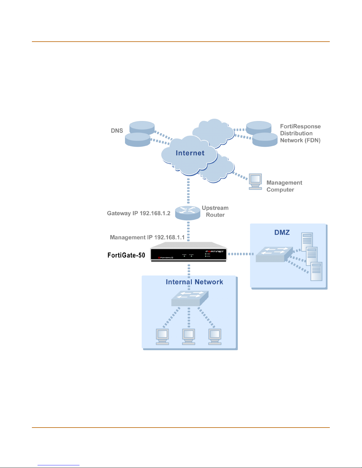
Transparent mode installation Transparent mode configuration examples
Example default route to an external network
Figure 7 shows a FortiGate unit where all destinations, including the management
computer, are located on the external network. To reach these destinations, the
FortiGate unit must connect to the “upstream” router leading to the external network.
To facilitate this connection, you must enter a single default route that points to the
upstream router as the next hop/default gateway.
Figure 7: Default route to an external network
General configuration steps
1 Set the FortiGate unit to operate in Transparent mode.
2 Configure the Management IP address and Netmask of the FortiGate unit.
3 Configure the default route to the external network.
FortiGate-50R Installation and Configuration Guide 47
Page 48

Transparent mode configuration examples Transparent mode installation
Web-based manager example configuration steps
To configure basic Transparent mode settings and a default route using the
web-based manager:
1 Go to System > Status.
• Select Change to Transparent Mode.
• Select Transparent in the Operation Mode list.
•Select OK.
The FortiGate unit changes to Transparent mode.
2 Go to System > Network > Management.
• Change the Management IP and Netmask:
IP: 192.168.1.1
Mask: 255.255.255.0
• Select Apply.
3 Go to System > Network > Routing.
• Select New to add the default route to the external network.
Destination IP: 0.0.0.0
Mask: 0.0.0.0
Gateway: 192.168.1.2
•Select OK.
CLI configuration steps
To configure the Fortinet basic settings and a default route using the CLI:
1 Change the system to operate in Transparent Mode.
set system opmode transparent
2 Add the Management IP address and Netmask.
set system management ip 192.168.1.1 255.255.255.0
3 Add the default route to the external network.
set system route number 1 gw1 192.168.1.2
Example static route to an external destination
Figure 8 shows a FortiGate unit that requires routes to the FDN located on the
external network. The Fortigate unit does not require routes to the DNS servers or
management computer because they are located on the internal network.
To connect to the FDN, you would typically enter a single default route to the external
network. However, to provide an extra degree of security, you could enter static routes
to a specific FortiResponse server in addition to a default route to the external
network. If the static route becomes unavailable (perhaps because the IP address of
the FortiResponse server changes) the FortiGate unit will still be able to receive
antivirus and NIDS updates from the FDN using the default route.
48 Fortinet Inc.
Page 49

Transparent mode installation Transparent mode configuration examples
Note: This is an example configuration only. To configure a static route, you require a
destination IP address.
Figure 8: Static route to an external destination
General configuration steps
1 Set the FortiGate unit to operate in Transparent mode.
2 Configure the Management IP address and Netmask of the FortiGate unit.
3 Configure the static route to the FortiResponse server.
4 Configure the default route to the external network.
FortiGate-50R Installation and Configuration Guide 49
Page 50

Transparent mode configuration examples Transparent mode installation
Web-based manager example configuration steps
To configure the basic FortiGate settings and a static route using the web-based
manager:
1 Go to System > Status.
• Select Change to Transparent Mode.
• Select Transparent in the Operation Mode list.
•Select OK.
The FortiGate unit changes to Transparent mode.
2 Go to System > Network > Management.
• Change the Management IP and Netmask:
IP: 192.168.1.1
Mask: 255.255.255.0
• Select Apply.
3 Go to System > Network > Routing.
• Select New to add the static route to the FortiResponse server.
Destination IP: 24.102.233.5
Mask: 255.255.255.0
Gateway: 192.168.1.2
•Select OK.
• Select New to add the default route to the external network.
Destination IP: 0.0.0.0
Mask: 0.0.0.0
Gateway: 192.168.1.2
•Select OK.
CLI configuration steps
To configure the Fortinet basic settings and a static route using the CLI:
1 Set the system to operate in Transparent Mode.
set system opmode transparent
2 Add the Management IP address and Netmask.
set system management ip 192.168.1.1 255.255.255.0
3 Add the static route to the primary FortiResponse server.
set system route number 1 dst 24.102.233.5 255.255.255.0 gw1
192.168.1.2
4 Add the default route to the external network.
set system route number 2 gw1 192.168.1.2
50 Fortinet Inc.
Page 51

Transparent mode installation Transparent mode configuration examples
Example static route to an internal destination
Figure 9 shows a FortiGate unit where the FDN is located on an external subnet and
the management computer is located on a remote, internal subnet. To reach the FDN,
you need to enter a single default route that points to the upstream router as the next
hop/default gateway. To reach the management computer, you need to enter a single
static route that leads directly to it. This route will point to the internal router as the
next hop. (No route is required for the DNS servers because they are on the same
layer 3 subnet as the FortiGate unit.)
Figure 9: Static route to an internal destination
General configuration steps
1 Set the unit to operate in Transparent mode.
2 Configure the Management IP address and Netmask of the FortiGate unit.
3 Configure the static route to the management computer on the internal network.
4 Configure the default route to the external network.
FortiGate-50R Installation and Configuration Guide 51
Page 52

Transparent mode configuration examples Transparent mode installation
Web-based manager example configuration steps
To configure the FortiGate basic settings, a static route, and a default route using the
web-based manager:
1 Go to System > Status.
• Select Change to Transparent Mode.
• Select Transparent in the Operation Mode list.
•Select OK.
The FortiGate unit changes to Transparent mode.
2 Go to System > Network > Management.
• Change the Management IP and Netmask:
IP: 192.168.1.1
Mask: 255.255.255.0
• Select Apply.
3 Go to System > Network > Routing.
• Select New to add the static route to the management computer.
Destination IP: 172.16.1.11
Mask: 255.255.255.0
Gateway: 192.168.1.3
•Select OK.
• Select New to add the default route to the external network.
Destination IP: 0.0.0.0
Mask: 0.0.0.0
Gateway: 192.168.1.2
•Select OK.
CLI configuration steps
To configure the FortiGate basic settings, a static route, and a default route using the
CLI:
1 Set the system to operate in Transparent Mode.
set system opmode transparent
2 Add the Management IP address and Netmask.
set system management ip 192.168.1.1 255.255.255.0
3 Add the static route to the management computer.
set system route number 1 dst 172.16.1.11 255.255.255.0 gw1
192.168.1.3
4 Add the default route to the external network.
set system route number 2 gw1 192.168.1.2
52 Fortinet Inc.
Page 53

FortiGate-50R Installation and Configuration Guide Version 2.50 MR2
System status
You can connect to the web-based manager and go to System > Status to view the
current status of your FortiGate unit. The status information that is displayed includes
the current firmware version, the current virus and attack definitions, and the FortiGate
unit serial number.
If you have logged into the web-based manager using the admin administrator
account, you can use System Status to make any of the following changes to the
FortiGate system settings:
• Changing the FortiGate host name
• Changing the FortiGate firmware
• Manual virus definition updates
• Manual attack definition updates
• Backing up system settings
• Restoring system settings
• Restoring system settings to factory defaults
• Changing to Transparent mode
• Changing to NAT/Route mode
• Restarting the FortiGate unit
• Shutting down the FortiGate unit
If you log into the web-based manager with any other administrator account, you can
go to System > Status to view the system settings including:
• Displaying the FortiGate serial number
• Displaying the FortiGate up time
All administrative users can also go to System > Status > Monitor and view
FortiGate system status. System status displays FortiGate health monitoring
information including CPU and memory status, Session and network status.
• System status
All administrative users can also go to System > Status > Session and view the
active communication sessions to and through the FortiGate unit.
• Session list
FortiGate-50R Installation and Configuration Guide 53
Page 54

Changing the FortiGate host name System status
Changing the FortiGate host name
The FortiGate host name appears on the System > Status page and on the FortiGate
CLI prompt. The host name is also used as the SNMP System Name (see
“Configuring SNMP” on page 106).
The default host name is FortiGate-50.
To change the FortiGate host name:
1 Go to System > Status.
2 Select Edit Host Name .
3 Enter a new host name.
4 Select OK.
The new host name appears on the System Status page and is added to the SNMP
System Name.
Changing the FortiGate firmware
After you download a FortiGate firmware image from Fortinet, you can use the
procedures in Tab le 1 to install the firmware image on your FortiGate unit.
Table 1: Firmware upgrade procedures
Procedure Description
Upgrade to a new
firmware version
Revert to a previous
firmware version
Install a firmware
image from a system
reboot using the CLI
Test a new firmware
image before
installing it
Commonly-used web-based manager and CLI procedures to
upgrade to a new FortiOS firmware version or to a more recent
build of the same firmware version.
Use the web-based manager or CLI procedure to revert to a
previous firmware version. This procedure reverts your FortiGate
unit to its factory default configuration.
Use this procedure to install a new firmware version or revert to a
previous firmware version. You must run this procedure by
connecting to the CLI using the FortiGate console port and a nullmodem cable. This procedure reverts your FortiGate unit to its
factory default configuration.
Use this procedure to test a new firmware image before installing it.
You must run this procedure by connecting to the CLI using the
FortiGate console port and a null-modem cable. This procedure
temporarily installs a new firmware image using your current
configuration. You can test the firmware image before installing it
permanently. If the firmware image works correctly you can use
one of the other procedures listed in this table to install it
permanently.
54 Fortinet Inc.
Page 55

System status Changing the FortiGate firmware
Upgrade to a new firmware version
Use the following procedures to upgrade your FortiGate to a newer firmware version.
Upgrading the firmware using the web-based manager
Note: Installing firmware replaces your current antivirus and attack definitions with the
definitions included with the firmware release that you are installing. When you have installed
new firmware, use the procedure “Manually updating antivirus and attack definitions” on
page 75 to make sure that antivirus and attack definitions are up-to-date.
1 Copy the firmware image file to your management computer.
2 Login to the FortiGate web-based manager as the admin administrative user.
3 Go to System > Status.
4 Select Firmware Upgrade .
5 Enter the path and filename of the firmware image file, or select Browse and locate the
file.
6 Select OK.
The FortiGate unit uploads the firmware image file, upgrades to the new firmware
version, restarts, and displays the FortiGate login. This process takes a few minutes.
7 Login to the web-based manager.
8 Go to System > Status and check the Firmware Version to confirm that the firmware
upgrade has been installed successfully.
9 Use the procedure “Manually updating antivirus and attack definitions” on page 75 to
update antivirus and attack definitions.
Upgrading the firmware using the CLI
To use the following procedure you must have a TFTP server that you can connect to
from the FortiGate unit.
Note: Installing firmware replaces your current antivirus and attack definitions with the
definitions included with the firmware release that you are installing. When you have installed
new firmware, use the procedure “Manually updating antivirus and attack definitions” on
page 75 to make sure that antivirus and attack definitions are up-to-date. You can also use the
CLI command
definitions.
1 Make sure that the TFTP server is running.
2 Copy the new firmware image file to the root directory of the TFTP server.
3 Log into the CLI as the admin administrative user.
4 Make sure the FortiGate unit can connect to the TFTP server.
You can use the following command to ping the computer running the TFTP server.
For example, if the TFTP server's IP address is 192.168.1.168:
execute ping 192.168.1.168
execute updatecenter updatenow to update the antivirus and attack
FortiGate-50R Installation and Configuration Guide 55
Page 56

Changing the FortiGate firmware System status
5 Enter the following command to copy the firmware image from the TFTP server to the
FortiGate:
execute restore image <name_str> <tftp_ip>
Where <name_str> is the name of the firmware image file on the TFTP server and
<tftp_ip> is the IP address of the TFTP server. For example, if the firmware image
file name is FGT_300-v250-build045-FORTINET.out and the IP address of the
TFTP server is 192.168.1.168, enter:
execute restore image FGT_300-v250-build045-FORTINET.out
192.168.1.168
The FortiGate unit uploads the firmware image file, upgrades to the new firmware
version, and restarts. This process takes a few minutes.
6 Reconnect to the CLI.
7 To confirm that the new firmware image has been loaded, enter:
get system status
8 Use the procedure “Manually updating antivirus and attack definitions” on page 75 to
update antivirus and attack definitions, or from the CLI, enter:
execute updatecenter updatenow
9 To confirm that the antivirus and attack definitions have been updated, enter the
following command to display the antivirus engine, virus and attack definitions version,
contract expiry, and last update attempt information.
get system objver
Revert to a previous firmware version
Use the following procedures to revert your FortiGate unit to a previous firmware
version.
Reverting to a previous firmware version using the web-based
manager
The following procedures return your FortiGate unit to its factory default configuration
and delete NIDS user-defined signatures, web content lists, email filtering lists, and
changes to replacement messages.
Before running this procedure you can:
• Backup the FortiGate unit configuration, use the procedure “Backing up system
settings” on page 64.
• Backup the NIDS user defined signatures, see the FortiGate NIDS Guide
• Backup web content and email filtering lists, see the FortiGate Content Protection
Guide.
If you are reverting to a previous FortiOS version (for example, reverting from FortiOS
v2.50 to FortiOS v2.36) you may not be able to restore your previous configuration
from the backup configuration file.
1 Copy the firmware image file to your management computer.
2 Login to the FortiGate web-based manager as the admin administrative user.
56 Fortinet Inc.
Page 57

System status Changing the FortiGate firmware
Note: Installing firmware replaces your current antivirus and attack definitions with the
definitions included with the firmware release that you are installing. When you have installed
new firmware, use the procedure “Manually updating antivirus and attack definitions” on
page 75 to make sure that antivirus and attack definitions are up-to-date.
3 Go to System > Status.
4 Select Firmware Upgrade .
5 Enter the path and filename of the previous firmware image file, or select Browse and
locate the file.
6 Select OK.
The FortiGate unit uploads the firmware image file, reverts to the old firmware version,
resets the configuration, restarts, and displays the FortiGate login. This process takes
a few minutes.
7 Login to the web-based manager.
For information about logging into the web-based manager when the FortiGate unit is
set to factory defaults, see “Connecting to the web-based manager” on page 20.
8 Go to System > Status and check the Firmware Version to confirm that the firmware
has been installed successfully.
9 Restore your configuration.
See “Restoring system settings” on page 65 to restore your previous configuration.
10 Use the procedure “Manually updating antivirus and attack definitions” on page 75 to
update antivirus and attack definitions.
Reverting to a previous firmware version using the CLI
This procedure reverts your FortiGate unit to its factory default configuration and
deletes NIDS user-defined signatures, web content lists, email filtering lists, and
changes to replacement messages.
Before running this procedure you can:
• Backup the FortiGate unit configuration using the command execute backup
config.
• Backup the NIDS user defined signatures using the command execute backup
nidsuserdefsig
• Backup web content and email filtering lists, see the FortiGate Content Protection
Guide.
If you are reverting to a previous FortiOS version (for example, reverting from FortiOS
v2.50 to FortiOS v2.36) you may not be able to restore your previous configuration
from the backup configuration file.
Note: Installing firmware replaces your current antivirus and attack definitions with the
definitions included with the firmware release that you are installing. When you have installed
new firmware, use the procedure “Manually updating antivirus and attack definitions” on
page 75 to make sure that antivirus and attack definitions are up-to-date. You can also use the
CLI command execute updatecenter updatenow to update the antivirus and attack
definitions.
FortiGate-50R Installation and Configuration Guide 57
Page 58

Changing the FortiGate firmware System status
To use the following procedure you must have a TFTP server that you can connect to
from the FortiGate unit.
1 Make sure that the TFTP server is running.
2 Copy the new firmware image file to the root directory of the TFTP server.
3 Login to the FortiGate CLI as the admin administrative user.
4 Make sure the FortiGate unit can connect to the TFTP server.
You can use the following command to ping the computer running the TFTP server.
For example, if the TFTP server's IP address is 192.168.1.168:
execute ping 192.168.1.168
5 Enter the following command to copy the firmware image from the TFTP server to the
FortiGate unit:
execute restore image <name_str> <tftp_ip>
Where <name_str> is the name of the firmware image file on the TFTP server and
<tftp_ip> is the IP address of the TFTP server. For example, if the firmware image
file name is FGT_300-v250-build045-FORTINET.out and the IP address of the
TFTP server is 192.168.1.168, enter:
execute restore image FGT_300-v250-build045-FORTINET.out
192.168.1.168
The FortiGate unit uploads the firmware image file. Once the file has been uploaded a
message similar to the following is displayed:
Get image from tftp server OK.
This operation will downgarde the current firmware version!
Do you want to continue? (y/n)
6 Type Y
7 The FortiGate unit reverts to the old firmware version, resets the configuration to
factory defaults, and restarts. This process takes a few minutes.
8 Reconnect to the CLI.
For information about logging into the web-based manager when the FortiGate unit is
set to factory defaults, see “Connecting to the command line interface (CLI)” on
page 21.
9 To confirm that the new firmware image has been loaded, enter:
get system status
10 Restore your previous configuration. Use the following command:
execute restore config
11 Use the procedure “Manually updating antivirus and attack definitions” on page 75 to
update antivirus and attack definitions, or from the CLI, enter:
execute updatecenter updatenow
12 To confirm that the antivirus and attack definitions have been updated, enter the
following command to display the antivirus engine, virus and attack definitions version,
contract expiry, and last update attempt information.
get system objver
58 Fortinet Inc.
Page 59

System status Changing the FortiGate firmware
Install a firmware image from a system reboot using the CLI
This procedure installs a specified firmware image and resets the FortiGate unit to
default settings. You can use this procedure to upgrade to a new firmware version,
revert to an older firmware version, or to re-install the current firmware.
Note: There are a few variations on this procedure for different FortiGate BIOS versions. These
variations are explained in the procedure steps that are affected. The version of the BIOS
running on your FortiGate unit is displayed when you restart the FortiGate unit while accessing
the CLI by connecting to the FortiGate console port using a null-modem cable.
To run this procedure you:
• access the CLI by connecting to the FortiGate console port using a null-modem
cable,
• install a TFTP server that you can connect to from the FortiGate internal interface.
The TFTP server should be on the same subnet as the internal interface.
Before running this procedure you can:
• Backup the FortiGate unit configuration, use the procedure “Backing up system
settings” on page 64.
• Backup the NIDS user defined signatures, see the FortiGate NIDS Guide
• Backup web content and email filtering lists, see the FortiGate Content Protection
Guide.
If you are reverting to a previous FortiOS version (for example, reverting from FortiOS
v2.50 to FortiOS v2.36) you may not be able to restore your previous configuration
from the backup configuration file.
Note: Installing firmware replaces your current antivirus and attack definitions with the
definitions included with the firmware release that you are installing. When you have installed
new firmware, use the procedure “Manually updating antivirus and attack definitions” on
page 75 to make sure that antivirus and attack definitions are up-to-date.
To install firmware from a system reboot
1 Connect to the CLI using the null modem cable and FortiGate console port.
2 Make sure that the TFTP server is running.
3 Copy the new firmware image file to the root directory of your TFTP server.
4 Make sure that the internal interface is connected to the same network as the TFTP
server.
5 To confirm that the FortiGate unit can connect to the TFTP server, use the following
command to ping the computer running the TFTP server. For example, if the TFTP
server’s IP address is 192.168.1.168:
execute ping 192.168.1.168
FortiGate-50R Installation and Configuration Guide 59
Page 60

Changing the FortiGate firmware System status
6 Enter the following command to restart the FortiGate unit:
execute reboot
As the FortiGate units starts, a series of system startup messages are displayed.
When one of the following messages appears:
• FortiGate unit running v2.x BIOS
Press Any Key To Download Boot Image.
...
• FortiGate unit running v3.x BIOS
Press any key to enter configuration menu.....
......
7 Immediately press any key to interrupt the system startup.
I
Note: You only have 3 seconds to press any key. If you do not press any key soon enough, the
FortiGate unit reboots and you must log in and repeat the
execute reboot command.
If you successfully interrupt the startup process, one of the following messages
appears:
• FortiGate unit running v2.x BIOS
Enter TFTP Server Address [192.168.1.168]:
Go to step 9.
• FortiGate unit running v3.x BIOS
[G]: Get firmware image from TFTP server.
[F]: Format boot device.
[B]: Boot with backup firmware and set as default.
[Q]: Quit menu and continue to boot with default firmware.
[H]: Display this list of options.
Enter G,F,B,Q,or H:
8 Type G to get the new firmware image from the TFTP server.
9 Type the address of the TFTP server and press Enter.
The following message appears:
Enter Local Address [192.168.1.188]:
10 Type the address of the internal interface of the FortiGate unit and press Enter.
Note: The local IP address is only used to download the firmware image. After the firmware is
installed the address of this interface is changed back to the default IP address for this interface.
The following message appears:
Enter File Name [image.out]:
60 Fortinet Inc.
Page 61

System status Changing the FortiGate firmware
11 Enter the firmware image file name and press Enter.
The TFTP server uploads the firmware image file to the FortiGate unit and messages
similar to the following appear.
• FortiGate unit running v2.x BIOS
Do You Want To Save The Image? [Y/n]
Type Y.
• FortiGate unit running v3.x BIOS
Save as Default firmware/Run image without saving:[D/R]
Save as Default firmware/Backup firmware/Run image without
saving:[D/B/R]
Type D.
The FortiGate unit installs the new firmware image and restarts. The installation might
take a few minutes to complete.
Restoring your previous configuration
You can then restore your previous configuration. Begin by changing the interface
addresses if required. You can do this from the CLI using the command:
set system interface
After changing the interface addresses, you can access the FortiGate unit from the
web-based manager and restore your configuration.
To restore your FortiGate unit configuration, see “Restoring system settings” on
page 65. To restore NIDS user defined signatures, see the FortiGate NIDS Guide. To
restore web content and email filtering lists, see the FortiGate Content Protection
Guide.
If you are reverting to a previous firmware version (for example, reverting from
FortiOS v2.50 to FortiOS v2.36) you may not be able to restore your previous
configuration from the backup up configuration file.
12 Update the virus and attack definitions to the most recent version, see “Manually
updating antivirus and attack definitions” on page 75.
Test a new firmware image before installing it
You can test a new firmware image by installing the firmware image from a system
reboot and saving it to system memory. After completing this procedure the FortiGate
unit operates using the new firmware image with the current configuration. This new
firmware image is not permanently installed. The next time the FortiGate unit restarts
it will be operating with the originally installed firmware image using the current
configuration. If the new firmware image operates successfully, you can install it
permanently using the procedure “Upgrade to a new firmware version” on page 55.
To run this procedure you:
• access the CLI by connecting to the FortiGate console port using a null-modem
cable,
• install a TFTP server that you can connect to from the FortiGate internal interface.
The TFTP server should be on the same subnet as the internal interface.
FortiGate-50R Installation and Configuration Guide 61
Page 62

Changing the FortiGate firmware System status
To test a new firmware image:
1 Connect to the CLI using a null modem cable and FortiGate console port.
2 Make sure the TFTP server is running.
3 Copy the new firmware image file to the root directory of the TFTP server.
4 Make sure that the internal interface is connected to the same network as the TFTP
server.
You can use the following command to ping the computer running the TFTP server.
For example, if the TFTP server's IP address is 192.168.1.168:
execute ping 192.168.1.168
5 Enter the following command to restart the FortiGate unit:
execute reboot
6 As the FortiGate unit reboots, press any key to interrupt the system startup.
As the FortiGate units starts, a series of system startup messages are displayed.
When one of the following messages appears:
• FortiGate unit running v2.x BIOS
Press Any Key To Download Boot Image.
...
• FortiGate unit running v3.x BIOS
Press any key to enter configuration menu.....
......
7 Immediately press any key to interrupt the system startup.
I
Note: You only have 3 seconds to press any key. If you do not press any key soon enough, the
FortiGate unit reboots and you must log in and repeat the execute reboot command.
If you successfully interrupt the startup process, one of the following messages
appears:
• FortiGate unit running v2.x BIOS
Enter TFTP Server Address [192.168.1.168]:
Go to step 9.
• FortiGate unit running v3.x BIOS
[G]: Get firmware image from TFTP server.
[F]: Format boot device.
[Q]: Quit menu and continue to boot with default firmware.
[H]: Display this list of options.
Enter G,F,Q,or H:
8 Type G to get the new firmware image from the TFTP server.
9 Type the address of the TFTP server and press Enter.
The following message appears:
Enter Local Address [192.168.1.188]:
10 Type the address of the internal interface of the FortiGate unit and press Enter.
62 Fortinet Inc.
Page 63

System status Manual virus definition updates
Note: The local IP address is only used to download the firmware image. After the firmware is
installed the address of this interface is changed back to the default IP address for this interface.
The following message appears:
Enter File Name [image.out]:
11 Enter the firmware image file name and press Enter.
The TFTP server uploads the firmware image file to the FortiGate unit and messages
similar to the following appear.
• FortiGate unit running v2.x BIOS
Do You Want To Save The Image? [Y/n]
Type N.
• FortiGate unit running v3.x BIOS
Save as Default firmware/Run image without saving:[D/R]
Type R.
The FortiGate image is installed to system memory and the FortiGate starts running
the new firmware image but with its current configuration.
12 You can login to the CLI or the web-based manager using any administrative account.
13 To confirm that the new firmware image has been loaded, from the CLI enter:
get system status
You can test the new firmware image as required.
Manual virus definition updates
The System > Status page of the FortiGate web-based manager displays the current
installed versions of the FortiGate Antivirus Definitions. You can use the following
procedure to update the antivirus definitions manually.
Note: To configure the FortiGate unit for automatic antivirus definitions updates, see “Virus and
attack definitions updates and registration” on page 71. You can also manually initiate an
antivirus definitions update by going to System > Update and selecting Update Now.
1 Download the latest antivirus definitions update file from Fortinet and copy it to the
computer that you use to connect to the web-based manager.
2 Start the web-based manager and go to System > Status.
3 To the right of the Antivirus Definitions Version, select Definitions Update .
4 Enter the path and filename for the antivirus definitions update file, or select Browse
and locate the antivirus definitions update file.
5 Select OK to copy the antivirus definitions update file to the FortiGate unit.
The FortiGate unit updates the antivirus definitions. This takes about 1 minute.
6 Go to System > Status to confirm that the Antivirus Definitions Version information
has been updated.
FortiGate-50R Installation and Configuration Guide 63
Page 64

Manual attack definition updates System status
Manual attack definition updates
The System > Status page of the FortiGate web-based manager displays the current
installed versions of the FortiGate Attack Definitions used by the Network Intrusion
Detection System (NIDS). You can use the following procedure to update the attack
definitions manually.
Note: To configure the FortiGate unit for automatic attack definitions updates, see “Virus and
attack definitions updates and registration” on page 71. You can also manually initiate an attack
definitions update by going to System > Update and selecting Update Now.
1 Download the latest attack definitions update file from Fortinet and copy it to the
computer that you use to connect to the web-based manager.
2 Start the web-based manager and go to System > Status.
3 To the right of the Attack Definitions Version, select Definitions Update .
4 Enter the path and filename for the attack definitions update file, or select Browse and
locate the attack definitions update file.
5 Select OK to copy the attack definitions update file to the FortiGate unit.
The FortiGate unit updates the attack definitions. This takes about 1 minute.
6 Go to System > Status to confirm that the Attack Definitions Version information has
been updated.
Displaying the FortiGate serial number
1 Go to System > Status.
The serial number is displayed in the System Status page of the web-based manager.
The serial number is specific to the FortiGate unit and does not change with firmware
upgrades.
Displaying the FortiGate up time
1 Go to System > Status.
The FortiGate up time displays the time in days, hours, and minutes since the
FortiGate unit was last started.
Backing up system settings
You can back up system settings by downloading them to a text file on the
management computer:
1 Go to System > Status.
2 Select System Settings Backup.
3 Select Backup System Settings.
4 Type a name and location for the file.
The system settings file is backed up to the management computer.
5 Select Return to go back to the Status page.
64 Fortinet Inc.
Page 65

System status Restoring system settings
!
Restoring system settings
You can restore system settings by uploading a previously downloaded system
settings text file:
1 Go to System > Status.
2 Select System Settings Restore.
3 Enter the path and filename of the system settings file, or select Browse and locate
the file.
4 Select OK to restore the system settings file to the FortiGate unit.
The FortiGate unit restarts, loading the new system settings.
5 Reconnect to the web-based manager and review your configuration to confirm that
the uploaded system settings have taken effect.
Restoring system settings to factory defaults
Use the following procedure to restore system settings to the values set at the factory.
This procedure does not change the firmware version or the antivirus or attack
definitions.
Caution: This procedure deletes all changes that you have made to the FortiGate configuration
and reverts the system to its original configuration, including resetting interface addresses.
1 Go to System > Status.
2 Select Restore Factory Defaults.
3 Select OK to confirm.
The FortiGate unit restarts with the configuration that it had when it was first powered
on.
4 Reconnect to the web-based manager and review the system configuration to confirm
that it has been reset to the default settings.
To restore your system settings, see “Restoring system settings” on page 65.
Changing to Transparent mode
Use the following procedure to switch the FortiGate unit from NAT/Route mode to
Transparent mode. When the FortiGate unit has changed to Transparent mode its
configuration resets to Transparent mode factory defaults.
1 Go to System > Status.
2 Select Change to Transparent Mode.
3 Select Transparent in the operation mode list.
4 Select OK.
The FortiGate unit changes operation mode.
FortiGate-50R Installation and Configuration Guide 65
Page 66

Changing to NAT/Route mode System status
5 To reconnect to the web-based manager, connect to the interface configured for
Transparent mode management access and browse to https:// followed by the
Transparent mode management IP address.
By default in Transparent mode, you can connect to the internal interface. The default
Transparent mode management IP address is 10.10.10.1.
Changing to NAT/Route mode
Use the following procedure to switch the FortiGate unit from Transparent mode to
NAT/Route mode. When the FortiGate unit has changed to NAT/Route mode its
configuration resets to NAT/Route mode factory defaults.
1 Go to System > Status.
2 Select Change to NAT Mode.
3 Select NAT/Route in the operation mode list.
4 Select OK.
The FortiGate unit changes operation mode.
5 To reconnect to the web-based manager you must connect to the interface configured
by default for management access.
By default in NAT/Route mode, you can connect to the internal interface. The default
Transparent mode management IP address is 192.168.1.99.
See “Connecting to the web-based manager” on page 20 or “Connecting to the
command line interface (CLI)” on page 21.
Restarting the FortiGate unit
1 Go to System > Status.
2 Select Restart.
The FortiGate unit restarts.
Shutting down the FortiGate unit
1 Go to System > Status.
2 Select Shutdown.
The FortiGate unit shuts down and all traffic flow stops.
The FortiGate unit can only be restarted after shutdown by turning the power off, then
on.
66 Fortinet Inc.
Page 67
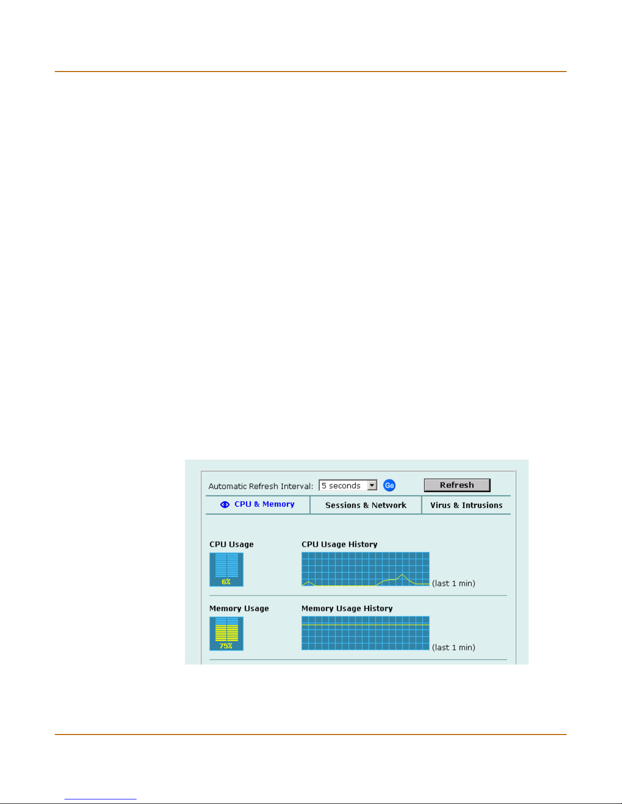
System status System status
System status
You can use the system status monitor to display FortiGate system health information.
The system health information includes memory usage, the number of active
communication sessions, and the amount of network bandwidth currently in use. The
web-based manager displays current statistics as well as statistics for the previous
minute.
You can also view current virus and intrusion status. The web-based manager
displays the current number of viruses and attacks as well as a graph of virus and
attack levels over the previous 20 hours.
In each case you can set an automatic refresh interval that updates the display every
5 to 30 seconds. You can also refresh the display manually.
• Viewing CPU and memory status
• Viewing sessions and network status
• Viewing virus and intrusions status
Viewing CPU and memory status
Current CPU and memory status indicates how close the FortiGate unit is to running
at full capacity. The web-based manager displays CPU and memory usage for core
processes only. CPU and memory use for management processes (for example, for
HTTPS connections to the web-based manager) is excluded.
If CPU and memory use is low, the FortiGate unit is able to process much more
network traffic than is currently running. If CPU and memory use is high, the FortiGate
unit is performing near its full capacity. Placing additional demands on the system
could lead to traffic processing delays.
Figure 1: CPU and memory status monitor
CPU and memory intensive processes such as encrypting and decrypting IPSec VPN
traffic, virus scanning, and processing high levels of network traffic containing small
packets will increase CPU and memory usage.
FortiGate-50R Installation and Configuration Guide 67
Page 68

System status System status
1 Go to System > Status > Monitor.
CPU & Memory status is displayed. The display includes bar graphs of current CPU
and memory usage as well as line graphs of CPU and memory usage for the last
minute.
2 Set the automatic refresh interval and select Go to control how often the web-based
manager updates the display.
More frequent updates use system resources and increase network traffic. However,
this only occurs when you are viewing the display using the web-based manager.
3 Select Refresh to manually update the information displayed.
Viewing sessions and network status
Use the session and network status display to track how many network sessions the
FortiGate unit is processing and to see what effect the number of sessions has on the
available network bandwidth. Also, by comparing CPU and memory usage with
session and network status you can see how much demand network traffic is placing
on system resources.
Sessions displays the total number of sessions being processed by the FortiGate unit
on all interfaces. Sessions also displays the sessions as a percentage of the
maximum number of sessions that the FortiGate unit is designed to support.
Network utilization displays the total network bandwidth being used through all
FortiGate interfaces. Network utilization also displays network utilization as a
percentage of the maximum network bandwidth that can be processed by the
FortiGate unit.
1 Go to System > Status > Monitor.
2 Select Sessions & Network.
Sessions and network status is displayed. The display includes bar graphs of the
current number of sessions and current network utilization as well as line graphs of
session and network utilization usage for the last minute. The line graph scales are
shown in the upper left corner of the graph.
Figure 2: Sessions and network status monitor
68 Fortinet Inc.
Page 69

System status System status
3 Set the automatic refresh interval and select Go to control how often the web-based
manager updates the display.
More frequent updates use system resources and increase network traffic. However,
this only occurs when you are viewing the display using the web-based manager.
4 Select Refresh to manually update the information displayed.
Viewing virus and intrusions status
Use the virus and intrusions status display to track when viruses are found by the
FortiGate antivirus system and to track when the NIDS detects a network-based
attack.
1 Go to System > Status > Monitor.
2 Select Virus & Intrusions.
Virus and intrusions status is displayed. The display includes bar graphs of the
number viruses and intrusions detected per hour as well as line graphs of the number
of viruses and intrusions detected for the last 20 hours.
Figure 3: Sessions and network status monitor
3 Set the automatic refresh interval and select Go to control how often the web-based
manager updates the display.
More frequent updates use system resources and increase network traffic. However,
this only occurs when you are viewing the display using the web-based manager. The
line graph scales are shown on the upper right corner of the graph.
4 Select Refresh to manually update the information displayed.
FortiGate-50R Installation and Configuration Guide 69
Page 70
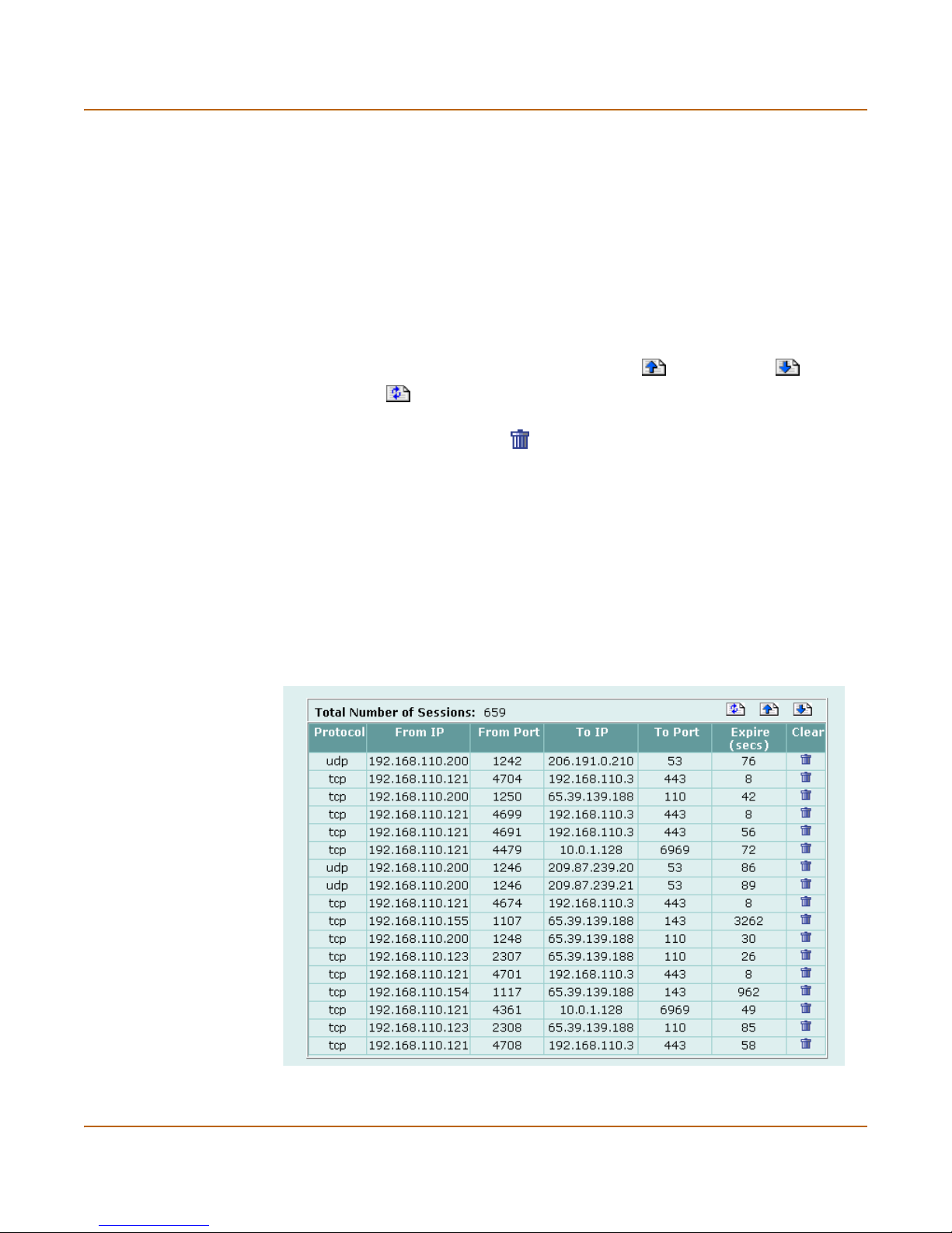
Session list System status
Session list
The session list displays information about the communications sessions currently
being processed by the FortiGate unit. You can use the session list to view current
sessions. FortiGate administrators with read and write permission, and the FortiGate
admin user can also stop active communication sessions.
Viewing the session list
1 Go to System > Status > Session.
The web-based manager displays the total number of active sessions in the FortiGate
unit session table and lists the top 16.
2 To page through the list of sessions, select Page Up or Page Down .
3 Select Refresh to update the session list.
4 If you have logged in as an administrative user with read and write privileges or as the
admin user, you can select Clear to stop any active session.
Each line of the session list displays the following information:
Protocol The service protocol of the connection, for example, udp, tcp, or icmp.
From IP The source IP address of the connection.
From Port The source port of the connection.
To IP The destination IP address of the connection.
To Po r t The destination port of the connection.
Expire The time, in seconds, before the connection expires.
Clear Stop an active communication session.
Figure 4: Example session list
70 Fortinet Inc.
Page 71

FortiGate-50R Installation and Configuration Guide Version 2.50 MR2
Virus and attack definitions updates
and registration
You can configure the FortiGate unit to connect to the FortiResponse Distribution
Network (FDN) to update the antivirus and attack definitions and antivirus engine. You
have the following update options:
• Request updates from the FDN manually,
• Schedule updates to automatically request the latest versions hourly, daily, or
weekly
• Push updates so that the FDN contacts your FortiGate unit when a new update is
available.
To receive scheduled updates and push updates, you must register the FortiGate unit
on the Fortinet Support web page.
This chapter describes:
• Updating antivirus and attack definitions
• Registering FortiGate units
• Updating registration information
• Registering a FortiGate unit after an RMA
Updating antivirus and attack definitions
You can configure the FortiGate unit to connect to the FortiResponse Distribution
Network (FDN) to automatically receive the latest antivirus and attack definitions and
antivirus engine updates. The FortiGate unit supports the following antivirus and
attack definition update features:
• User-initiated manual updates from the FDN,
• Hourly, daily, or weekly scheduled antivirus and attack definition and antivirus
engine updates from the FDN,
• Push updates from the FDN,
• View the update status including version numbers, expiry dates, and update dates
and times,
• Push updates through a NAT device.
FortiGate-50R Installation and Configuration Guide 71
Page 72

Updating antivirus and attack definitions Virus and attack definitions updates and registration
The System > Update page web-based manager displays the following antivirus and
attack definition update information:
Version Displays the current antivirus engine, virus definition, and attack definition
Expiry date Displays the expiry date of your license for antivirus engine, virus definition,
Last update
attempt
Last update
status
version numbers.
and attack definition updates.
Displays the date and time on which the FortiGate unit last attempted to
download antivirus engine, virus definition, and attack definition updates.
Displays the success or failure of the last update attempt. No updates means
the last update attempt was successful but no new updates are available.
Update succeeded or similar messages mean the last update attempt was
successful and new updates were installed. Other messages can indicate
that the FortiGate was not able to connect to the FDN and other error
conditions.
This section describes:
• Connecting to the FortiResponse Distribution Network
• Configuring scheduled updates
• Configuring update logging
• Adding an override server
• Manually updating antivirus and attack definitions
• Configuring push updates
• Push updates through a NAT device
• Scheduled updates through a proxy server
Connecting to the FortiResponse Distribution Network
Before the FortiGate unit can receive antivirus and attack updates, it must be able to
connect to the FortiResponse Distribution Network (FDN). The FortiGate unit uses
HTTPS on port 8890 to connect to the FDN. The FortiGate external interface must
have a path to the internet using port 8890. To configure scheduled updates, see
“Configuring scheduled updates” on page 73.
You can also configure the FortiGate unit to allow push updates. Push updates are
provided to the FortiGate unit from the FDN using HTTPS on UDP port 9443. To
receive push updates, the FDN must have a path to the FortiGate external interface
using UDP port 9443. To configure push updates, see “Configuring push updates” on
page 75.
The FDN is a world-wide network of FortiResponse Distribution Servers (FDSs).
When your FortiGate unit connects to the FDN it actually connects to the nearest
FDS. To do this, all FortiGate units are programmed with a list of FDS addresses
sorted by nearest time zone according to the time zone configured for the FortiGate
unit. To make sure the FortiGate unit receives updates from the nearest FDS, go to
System > Config > Time and make sure you have selected the correct time zone for
your area.
72 Fortinet Inc.
Page 73

Virus and attack definitions updates and registration Updating antivirus and attack definitions
To make sure the FortiGate unit can connect to the FDN:
1 Go to System > Config > Time and make sure the time zone is set to the correct time
zone for your area.
2 Go to System > Update.
3 Select Refresh.
The FortiGate unit tests its connection to the FDN. The test results are displayed at
the top of the System Update page.
Table 1: Connections to the FDN
Connections Status Comments
Available The FortiGate unit can connect to the FDN. You can
Not available The FortiGate unit cannot connect to the FDN. You
FortiResponse
Distribution
Network
Available The FDN can connect to the FortiGate unit to send
Not available The FDN cannot connect to the FortiGate unit to send
Push Update
configure the FortiGate unit for scheduled updates.
See “Configuring scheduled updates” on page 73.
must configure your FortiGate unit and your network so
that the FortiGate unit can connect to the Internet and
to the FDN. For example, you may need to add routes
to the FortiGate routing table or configure your network
to allow the FortiGate unit to use HTTPS on port 8890
to connect to the Internet.
You may also have to connect to an override
FortiResponse server to receive updates. See
“Configuring update logging” on page 74.
push updates. You can configure the FortiGate unit to
receive push updates. See “Configuring push updates”
on page 75.
push updates. Push updates may not be available if
you have not registered the FortiGate unit (see
“Registering the FortiGate unit” on page 82), if there is
a NAT device installed between the FortiGate unit and
the FDN (see “Push updates through a NAT device” on
page 76), or if your FortiGate unit connects to the
Internet using a proxy server (see “Scheduled updates
through a proxy server” on page 80).
Configuring scheduled updates
You can configure the FortiGate unit to check for and download updated definitions
hourly, daily, or weekly according to the schedule you specify.
1 Go to System > Update.
2 Select Scheduled Update.
3 Select whether to check for and download updates hourly, daily, or weekly:
Hourly Once every 1 to 23 hours. Select the number of hours and minutes between
Daily Once a day. You can specify the time of day to check for updates.
Weekly Once a week. You can specify the day of the week and the time of day to check
FortiGate-50R Installation and Configuration Guide 73
each update request.
for updates.
Page 74

Updating antivirus and attack definitions Virus and attack definitions updates and registration
4 Select Apply.
The FortiGate unit starts the next scheduled update according to the new update
schedule.
Whenever a scheduled update is run, the event is recorded in the FortiGate event log.
Figure 1: Configuring automatic antivirus and attack definitions updates
Configuring update logging
Use the following procedure to configure FortiGate logging to record log messages
when the FortiGate unit updates antivirus and attack definitions. Update log messages
are recorded on the FortiGate Event log.
1 Go to Log&Report > Log Setting.
2 Select Config Policy for the type of logs that the FortiGate unit is configured to record.
See “Recording logs” on page 221.
3 Select Update to record log messages when the FortiGate unit updates antivirus and
attack definitions.
4 Select the following update log options:
Failed Update The FortiGate unit records a log message whenever and update attempt
Successful
Update
FDN error The FortiGate unit records a log messages whenever it cannot connect to
fails.
The Fortigate unit records a log message whenever an update attempt is
successful.
the FDN or whenever it receives an error message from the FDN.
5 Select OK.
74 Fortinet Inc.
Page 75

Virus and attack definitions updates and registration Updating antivirus and attack definitions
Adding an override server
If you cannot connect to the FDN or if your organization provides antivirus and attack
updates using their own FortiResponse server, you can use the following procedure to
add the IP address of an override FortiResponse server.
1 Go to System > Update.
2 Select Use override server address and add the IP address of a FortiResponse
server.
3 Select Apply.
The FortiGate unit tests the connection to the override server.
If the FortiResponse Distribution Network setting changes to available, the FortiGate
unit has successfully connected to the override server.
If the FortiResponse Distribution Network stays set to not available, the FortiGate unit
cannot connect to the override server. Check the FortiGate configuration and the
network configuration to make sure you can connect to the override FortiResponse
server from the FortiGate unit.
Manually updating antivirus and attack definitions
You can use the following procedure to update the antivirus and attack definitions at
any time. To run this procedure the FortiGate unit must be able to connect to the FDN
or to an override FortiResponse server.
1 Go to System > Update.
2 Select Update Now to update the antivirus and attack definitions.
If the connection to the FDN or override server is successful, the web-based manager
displays a message similar to the following:
Your update request has been sent. Your database will be updated
in a few minutes. Please check your update page for the status
of the update.
After a few minutes, if an update is available, the System Update page lists new
version information for antivirus definitions, the antivirus engine, or for attack
definitions. The System Status page will also displays new dates and version numbers
for antivirus and attack definitions. Messages are recorded to the event log indicating
whether the update was successful or not.
Configuring push updates
The FDN can push updates to FortiGate units to provide the fastest possible response
to critical situations. You must register the FortiGate unit before it can receive push
updates. See “Registering the FortiGate unit” on page 82.
If the FDN must connect to the FortiGate unit through a NAT device, see “Push
updates through a NAT device” on page 76.
Push updates are not supported if the FortiGate unit must use a proxy server to
connect to the FDN. See “Scheduled updates through a proxy server” on page 80 for
more information.
FortiGate-50R Installation and Configuration Guide 75
Page 76

Updating antivirus and attack definitions Virus and attack definitions updates and registration
To enable push updates
1 Go to System > Update.
2 Select Allow Push Update.
3 Select Apply.
About push updates
When you configure a FortiGate unit to allow push updates, the FortiGate unit sends a
SETUP message to the FDN. The next time a new antivirus engine, new antivirus
definitions, or new attack definitions are released, the FDN notifies all FortiGate units
configured for push updates that a new update is available. Within 60 seconds of
receiving a push notification, the FortiGate unit attempts to request an update from the
FDN.
If available for your network configuration, configuring push updates is recommended
in addition to configuring scheduled updates. Push updates mean that on average the
FortiGate unit receives new updates sooner than if the FortiGate just receives
scheduled updates. However, scheduled updates make sure that the FortiGate unit
does eventually receives the latest updates.
Enabling push updates is not recommended as the only method for obtaining updates.
The push notification may not be received by the FortiGate unit. Also, when the
FortiGate unit receives a push notification it will only make one attempt to connect to
the FDN and download updates.
Push updates and external dynamic IP addresses
If the external interface of the FortiGate unit is configured with a dynamic IP address
(using PPPoE or DHCP), whenever the IP address of the external interface changes,
a SETUP message is sent to the FDN to notify it of the change. As long as this
SETUP message is sent, the FDN will have the most up-to-date IP address and the
next push notification is sent to this IP address.
Push updates through a NAT device
If the FDN can only connect to the FortiGate unit through a NAT device, you must
configure port forwarding on the NAT device and add the port forwarding information
to the push update configuration. Using port forwarding, the FDN connects to the
FortiGate unit using either port 9443 or an override push port that you assign.
Note: You cannot receive push updates through a NAT device if the external IP address of the
NAT device is dynamic (for example, set using PPPoE or DHCP).
76 Fortinet Inc.
Page 77
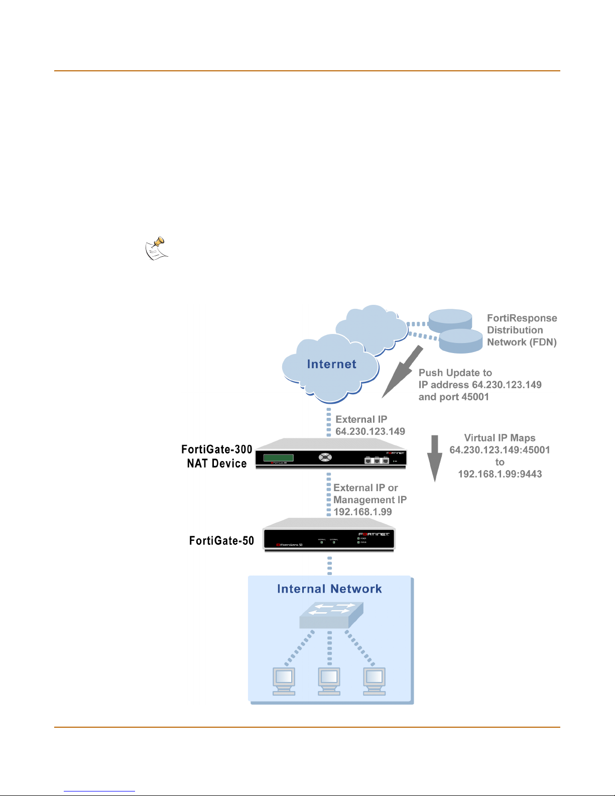
Virus and attack definitions updates and registration Updating antivirus and attack definitions
Example: push updates through a NAT device
This example describes how to configure a FortiGate NAT device to forward push
updates to a FortiGate unit installed on its internal network. For the FortiGate unit on
the internal network to receive push updates, the FortiGate NAT device must be
configured with a port forwarding virtual IP. This virtual IP maps the IP address of the
external interface of the FortiGate NAT device and a custom port to the IP address of
the FortiGate unit on the internal network. This IP address can either be the external
IP address of the FortiGate unit if it is operating in NAT/Route mode or the
Management IP address of the FortiGate unit if it is operating in Transparent mode.
Note: This example describes the configuration for a FortiGate NAT device. However, any NAT
device with a static external IP address that can be configured for port forwarding can be used.
Figure 2: Example network topology: Push updates through a NAT device
FortiGate-50R Installation and Configuration Guide 77
Page 78

Updating antivirus and attack definitions Virus and attack definitions updates and registration
General procedure
Use the following steps to configure the FortiGate NAT device and the FortiGate unit
on the Internal network so that the FortiGate unit on the Internal network can receive
push updates:
1 Add a port forwarding virtual IP to the FortiGate NAT device.
2 Add a firewall policy to the FortiGate NAT device that includes the port forwarding
virtual IP.
3 Configure the FortiGate unit on the internal network with an override push IP and port.
Note: Before completing the following procedure you should register the FortiGate unit on the
internal network so that it can receive push updates.
Adding a port forwarding virtual IP to the FortiGate NAT device
Use the following procedure to configure a FortiGate NAT device to use port
forwarding to forward push update connections from the FDN to a FortiGate unit on
the internal network.
To configure the FortiGate NAT device:
1 Go to Firewall > Virtual IP.
2 Select New.
3 Add a name for the virtual IP.
4 Select the External interface that the FDN connects to.
For the example topology, select the external interface.
5 Select Port Forwarding.
6 Enter the External IP address that the FDN connects to.
For the example topology, enter 64.230.123.149.
7 Enter the External Service Port that the FDN connects to.
For the example topology, enter 45001.
8 Set Map to IP to the IP address of the FortiGate unit on the internal network.
If the FortiGate unit is operating in NAT/Route mode, enter the IP address of the
external interface.
If the FortiGate unit is operating in Transparent mode, enter the management IP
address.
For the example topology, enter 192.168.1.99.
9 Set the Map to Port to 9443.
10 Set Protocol to UDP.
11 Select OK.
78 Fortinet Inc.
Page 79
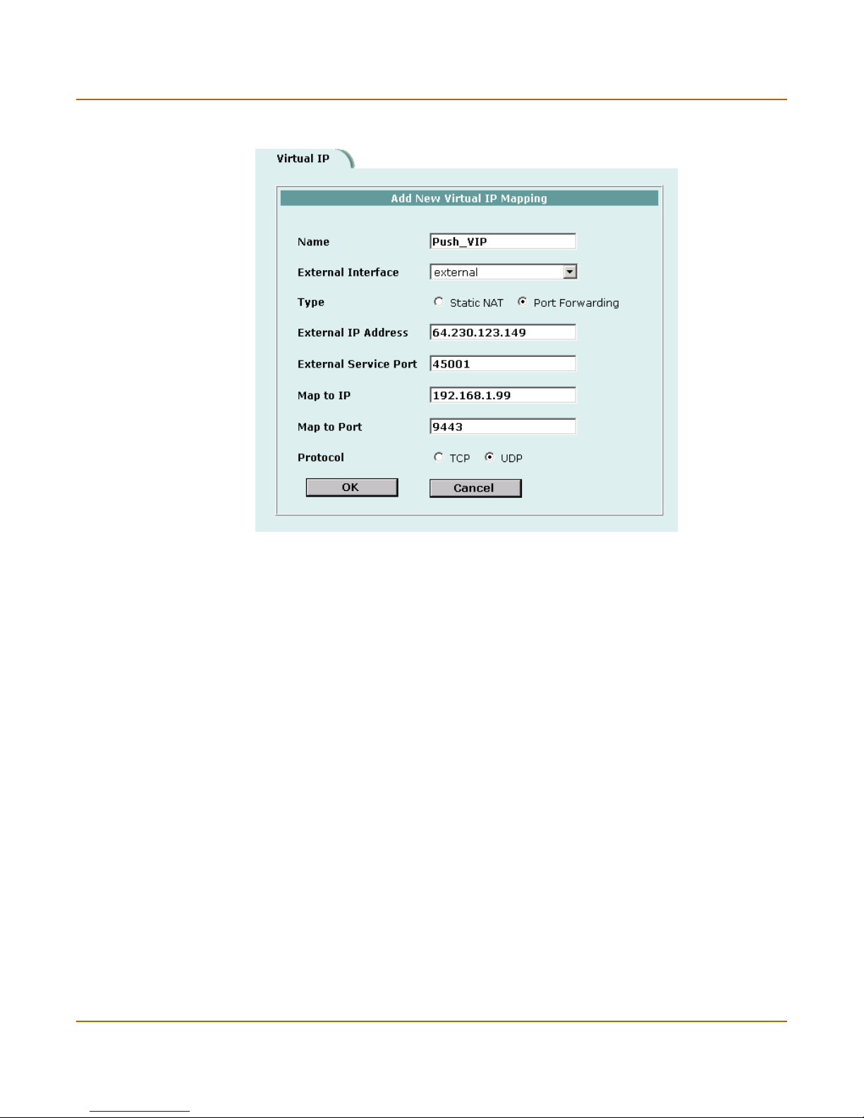
Virus and attack definitions updates and registration Updating antivirus and attack definitions
Figure 3: Push update port forwarding virtual IP
Adding a firewall policy for the port forwarding virtual IP
To configure the FortiGate NAT device:
1 Add a new external to internal firewall policy.
2 Configure the policy with the following settings:
Source External_All
Destination The virtual IP added above.
Schedule Always
Service ANY
Action Accept
NAT Selected.
3 Select OK.
Configure the FortiGate unit with an override push IP and port
To configure the FortiGate unit on the internal network:
1 Go to System > Update.
2 Select Allow Push Update.
3 Select Use override push.
4 Set IP to the External IP Address added to the virtual IP.
For the example topology, enter 64.230.123.149.
FortiGate-50R Installation and Configuration Guide 79
Page 80
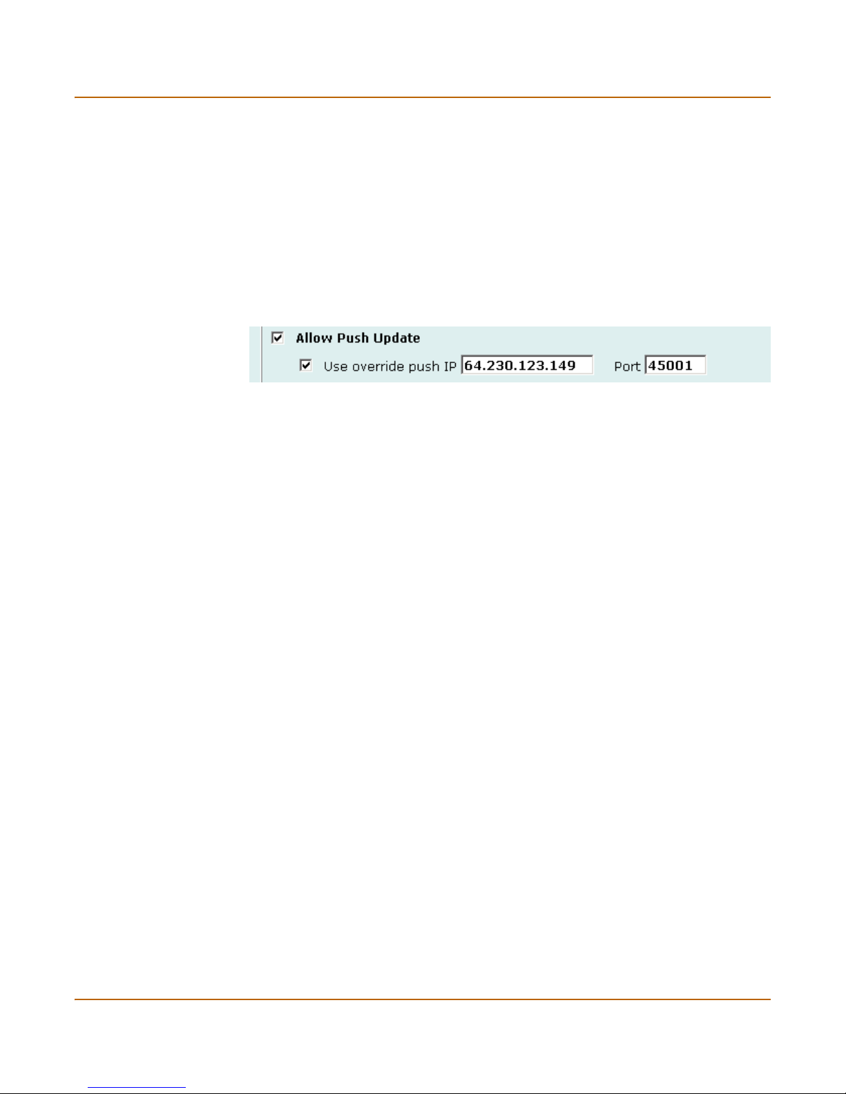
Updating antivirus and attack definitions Virus and attack definitions updates and registration
5 Set Port to the External Service Port added to the virtual IP.
For the example topology, enter 45001.
6 Select Apply.
The FortiGate unit sends the override push IP address and Port to the FDN. The FDN
will now use this IP address and port for push updates to the FortiGate unit on the
internal network.
If the External IP Address or External Service Port change, add the changes to the
Use override push configuration and select Apply to update the push information on
the FDN.
Figure 4: Example push update configuration
7 Select Apply.
8 You can select Refresh to make sure that push updates work.
Push Update should change to Available.
Scheduled updates through a proxy server
If your FortiGate unit must connect to the Internet through a proxy server, you can use
the set system autoupdate tunneling command to allow the FortiGate unit to
connect (or tunnel) to the FDN using the proxy server. Using the command you can
specify the IP address and port of the proxy server. As well, if the proxy server
requires authentication, you can add the user name and password required for the
proxy server to the autoupdate configuration. The full syntax for enabling updates
through a proxy server is:
set system autouopdate tunneling enable [address
<proxy-address_ip> [port <proxy-port> [username <username_str>
[password <password_str>]]]]
For example, if the IP address of the proxy server is 64.23.6.89 and its port is 8080,
enter the following command:
set system autouopdate tunneling enable address 64.23.6.89
port 8080
For more information about the set system autoupdate command, see Volume 6,
FortiGate CLI Reference Guide.
The FortiGate unit connects to the proxy server using the HTTP CONNECT method,
as described in RFC 2616. The FortiGate unit sends an HTTP CONNECT request to
the proxy server (optionally with authentication information) specifying the IP address
and port required to connect to the FDN. The proxy server establishes the connection
to the FDN and passes information between the FortiGate unit and the FDN.
The CONNECT method is used mostly for tunneling SSL traffic. Some proxy servers
won't allow the CONNECT to connect to just any port; they restrict the allowed ports to
the well known ports for HTTPS and perhaps some other similar services. Because
FortiGate autoupdates use HTTPS on port 8890 to connect to the FDN, your proxy
server may have to be configured to allow connections on this port.
80 Fortinet Inc.
Page 81

Virus and attack definitions updates and registration Registering FortiGate units
There are no special tunneling requirements if you have configured an override server
address to connect to the FDN.
Push updates are not supported if the FortiGate must connect to the Internet through
a proxy server.
Registering FortiGate units
After purchasing and installing a new FortiGate unit, you can register the unit using
the web-based manager by going to System > Update > Support, or by using a web
browser to connect to http://support.fortinet.com and selecting Product Registration.
Registration consists of entering your contact information and the serial numbers of
the FortiGate units you or your organization have purchased. Registration is quick and
easy. You can register multiple FortiGate units in a single session without re-entering
your contact information.
Once registration is completed, Fortinet sends a Support Login user name and
password to your email address. You can use this user name and password to log on
to the Fortinet support web site to:
• View your list of registered FortiGate units
• Register additional FortiGate units
• Add or change FortiCare Support Contract numbers for each FortiGate unit
• View and change registration information
• Download virus and attack definitions updates
• Download firmware upgrades
• Modify registration information after an RMA
Soon you will also be able to:
• Access Fortinet user documentation
• Access the Fortinet knowledge base
All registration information is stored in the Fortinet Customer Support database. This
information is used to make sure that your registered FortiGate units can be kept up to
date. All information is strictly confidential. Fortinet does not share this information
with any third party organizations for any reason.
This section describes:
• FortiCare Service Contracts
• Registering the FortiGate unit
FortiCare Service Contracts
Owners of a new FortiGate unit are entitled to 90 days of technical support services.
To continue receiving support services after the 90 day expiry date, you must
purchase a FortiCare Support Contract from an authorized Fortinet reseller or
distributor. Different levels of service are available so you can purchase the support
that you need. For maximum network protection, Fortinet strongly recommends that
all customers purchase a service contract that covers antivirus and attack definition
updates. See your Fortinet reseller or distributor for details of packages and pricing.
FortiGate-50R Installation and Configuration Guide 81
Page 82

Registering FortiGate units Virus and attack definitions updates and registration
To activate the FortiCare Support Contract, you must register the FortiGate unit and
add the FortiCare Support Contract number to the registration information. You can
also register the FortiGate unit without purchasing a FortiCare Support Contract. In
this case, when you do purchase a FortiCare Support Contract you can update the
registration information to add the support contract number.
A single FortiCare Support Contract can cover multiple FortiGate units. You must
enter the same service contract number for each of the FortiGate models covered by
the service contract.
Registering the FortiGate unit
Before registering a FortiGate unit, you require the following information:
• Your contact information including:
• First and last name
• Company name
• Email address (Your Fortinet support login user name and password will be
sent to this email address.)
•Address
• Contact phone number
• A security question and an answer to the security question.
This information is used for password recovery. The security question should be a
simple question that only you know the answer to. The answer should not be easy
to guess.
• The product model and serial number for each FortiGate unit to be registered.
The serial number is located on a label on the bottom of the FortiGate unit.
You can view the Serial number from the web-based manager by going to
System > Status.
The serial number is also available from the CLI using the get system status
command.
• FortiCare Support Contract numbers if you have purchased FortiCare Support
Contracts for the FortiGate units to be registered.
To register one or more FortiGate units
1 Go to System > Update > Support.
2 Enter your contact information into the product registration form.
82 Fortinet Inc.
Page 83

Virus and attack definitions updates and registration Registering FortiGate units
Figure 5: Registering a FortiGate unit (contact information and security question)
3 Provide a security question and an answer to the security question.
4 Select the model number of the Product Model to register.
5 Enter the Serial Number of the FortiGate unit.
6 If you have purchased a FortiCare Support Contract for this FortiGate unit, enter the
support contract number.
Figure 6: Registering a FortiGate unit (product information)
7 Select Finish.
If you have not entered a FortiCare Support Contract number (SCN) you can return to
the previous page to enter the number. If you do not have a FortiCare Support
Contract you can select Continue to complete the registration.
If you have entered a support contract number a real-time validation is performed to
verify that the SCN information matches the FortiGate unit. If the information doesn't
match you can try entering it again.
A web page is displayed that contains detailed information about the Fortinet technical
support services available to you for the registered FortiGate unit.
Your Fortinet support user name and password is sent to the email address provided
with your Contact information.
FortiGate-50R Installation and Configuration Guide 83
Page 84

Updating registration information Virus and attack definitions updates and registration
Updating registration information
You can use your Fortinet support user name and password to log on to the Fortinet
Support web site at any time to view or update your Fortinet support information.
This section describes:
• Recovering a lost Fortinet support password
• Viewing the list of registered FortiGate units
• Registering a new FortiGate unit
• Adding or changing a FortiCare Support Contract number
• Changing your Fortinet support password
• Changing your contact information or security question
• Downloading virus and attack definitions updates
Recovering a lost Fortinet support password
If you provided a security question and answer when you registered on the Fortinet
support web site, you can use the following procedure to receive a replacement
password. If you did not provide a security question and answer, contact Fortinet tech
support.
1 Go to System > Update > Support.
2 Select Support Login.
3 Enter your Fortinet support user name.
4 Select Forgot your password?
5 Enter your email address and select Submit.
The security question that you entered when you registered is displayed.
6 Enter the answer to your security question and select Get Password.
If you entered the correct answer to the security question, an email containing a new
password is sent to your email address. You can use your current user name and this
password to log into the Fortinet support web site.
7 Select Support Login.
8 When your new password arrives, enter your user name and new password to log into
the Fortinet support web site.
Viewing the list of registered FortiGate units
1 Go to System > Update > Support and select Support Login.
2 Enter your Fortinet support user name and password.
3 Select Login.
4 Select View Products.
The list of FortiGate products that you have registered is displayed. For each
FortiGate unit, the list includes the serial number and current support options for that
unit.
84 Fortinet Inc.
Page 85

Virus and attack definitions updates and registration Updating registration information
Figure 7: Sample list of registered FortiGate units
Registering a new FortiGate unit
1 Go to System > Update > Support and select Support Login.
2 Enter your Fortinet support user name and password.
3 Select Login.
4 Select Add Registration.
5 Select the model number of the Product Model to register.
6 Enter the Serial Number of the FortiGate unit.
7 If you have purchased a FortiCare Support Contract for this FortiGate unit, enter the
support contract number.
8 Select Finish.
The list of FortiGate products that you have registered is displayed. The list now
includes the new FortiGate unit.
Adding or changing a FortiCare Support Contract number
1 Go to System > Update > Support and select Support Login.
2 Enter your Fortinet support user name and password.
3 Select Login.
4 Select Add/Change Contract number.
5 Select the Serial Number of the FortiGate unit for which to add or change a FortiCare
Support Contract number.
6 Add the new Support Contract number.
FortiGate-50R Installation and Configuration Guide 85
Page 86

Updating registration information Virus and attack definitions updates and registration
7 Select Finish.
The list of FortiGate products that you have registered is displayed. The list now
includes the new support contract information.
Changing your Fortinet support password
1 Go to System > Update > Support and select Support Login.
2 Enter your Fortinet support user name and password.
3 Select Login.
4 Select My Profile.
5 Select Change Password.
6 Enter your current password.
7 Enter and confirm a new password.
An email is sent to your email address confirming that your password has been
changed. Use your current user name and new password the next time you log into
the Fortinet tech support web site.
Changing your contact information or security question
1 Go to System > Update > Support and select Support Login.
2 Enter your Fortinet support user name and password.
3 Select Login.
4 Select My Profile.
5 Select Edit Profile.
6 Make the required changes to your contact information.
7 Make the required changes to your security question and answer.
8 Select Update Profile.
Your changes are saved to the Fortinet technical support database. If you changed
your contact information, the changes are displayed.
Downloading virus and attack definitions updates
Use the following procedure to manually download virus and attack definitions
updates. This procedure also describes how to install the definitions updates on your
FortiGate unit.
1 Go to System > Update > Support and select Support Login.
2 Enter your Fortinet support user name and password.
3 Select Login.
4 Select Download Virus/Attack Update.
5 If required, select the FortiOS version.
6 Select the virus and attack definitions to download.
86 Fortinet Inc.
Page 87

Virus and attack definitions updates and registration Registering a FortiGate unit after an RMA
Figure 8: Downloading virus and attack definition updates
For information about how to install the downloaded files, see “Manual virus definition
updates” on page 63 and “Manual attack definition updates” on page 64.
Registering a FortiGate unit after an RMA
The Return Material Authorization (RMA) process starts when a customer’s registered
FortiGate unit doesn't work properly due to a hardware failure. If this happens while
the FortiGate unit is still protected by hardware coverage, you can return the FortiGate
unit that is not functioning to your reseller or distributor.
The RMA is recorded and you will receive a replacement unit. Fortinet adds the RMA
information to the Fortinet support database. When you receive the replacement unit
you can use the following procedure to update your product registration information.
1 Go to System > Update > Support and select Support Login.
2 Enter your Fortinet support user name and password to log in.
3 Select Add Registration.
4 Select the link to replace a unit with a new unit from an RMA.
5 Select Finish.
The list of FortiGate products that you have registered is displayed. The list now
includes the replacement FortiGate unit. All support levels are transferred to the
replacement unit.
FortiGate-50R Installation and Configuration Guide 87
Page 88

Registering a FortiGate unit after an RMA Virus and attack definitions updates and registration
88 Fortinet Inc.
Page 89

FortiGate-50R Installation and Configuration Guide Version 2.50 MR2
Network configuration
Go to System > Network to make any of the following changes to the FortiGate
network settings:
• Configuring interfaces
• Adding DNS server IP addresses
• Configuring routing
• Providing DHCP services to your internal network
Configuring interfaces
Use the following procedures to configure interfaces:
• Viewing the interface list
• Bringing up an interface
• Changing an interface static IP address
• Adding a secondary IP address to an interface
• Adding a ping server to an interface
• Controlling management access to an interface
• Configuring traffic logging for connections to an interface
• Configuring the external interface with a static IP address
• Configuring the external interface for DHCP
• Configuring the external interface for PPPoE
• Changing the external interface MTU size to improve network performance
• Configuring the management interface (Transparent mode)
FortiGate-50R Installation and Configuration Guide 89
Page 90

Configuring interfaces Network configuration
Viewing the interface list
Use the following procedure to view the interface list.
1 Go to System > Interface.
The interface list is displayed. The interface list shows the following status information
for all of the FortiGate interfaces:
• The IP address of the interface
• The netmask of the interface
• The administrative access configuration for the interface
• The link status for the interface
If the link status is a green arrow, the interface is up and can accept network traffic.
If the link status is a red arrow, the interface is down and cannot accept traffic. To
bring an interface up, see the procedure “Bringing up an interface”.
Bringing up an interface
If the link status of an interface on the interface shows that it is down, you can use the
following procedure to bring the interface up.
1 Go to System > Interface.
The interface list is displayed.
2 Select Bring Up for the interface that you want to bring up.
Changing an interface static IP address
Use the following procedure to change the static IP address of any FortiGate
interface. You can also use this procedure to add an IP address to an interface.
1 Go to System > Network > Interface.
2 Select Modify for the interface to change.
3 Change the IP address and Netmask as required.
The IP address of the interface must be on the same subnet as the network the
interface is connecting to.
Two interfaces cannot have the same IP address and cannot have IP addresses on
the same subnet.
4 Select OK to save your changes.
If you changed the IP address of the interface that you are connecting to manage the
FortiGate unit, you must reconnect to the web-based manager using the new interface
IP address.
Adding a secondary IP address to an interface
You can use the CLI to add a secondary IP address to any FortiGate interface. The
secondary IP address cannot be the same as the primary IP address but it can be on
the same subnet.
To add a secondary IP address from the CLI enter the command:
set system interface internal config secip <second_ip>
<netmask_ip>
90 Fortinet Inc.
Page 91

Network configuration Configuring interfaces
You can also configure management access and add a ping server to the secondary
IP address.
set system interface <intf_str> config secallowaccess ping
https ssh snmp http telnet
set system interface <intf_str> config secgwdetect enable
Adding a ping server to an interface
Add a ping server to an interface if you want the FortiGate unit to confirm connectivity
with the next hop router on the network connected to the interface. Adding a ping
server is required for routing failover. See “Adding destination-based routes to the
routing table” on page 96.
1 Go to System > Network > Interface.
2 Select Modify for the interface to which to add a Ping server.
3 Set Ping Server to the IP address of the next hop router on the network connected to
the interface.
4 Select Enable.
The FortiGate unit uses dead gateway detection to ping the Ping Server IP address to
make sure that the FortiGate unit can connect to the this IP address. To configure
dead gateway detection, see “To modify the Dead Gateway Detection settings” on
page 103.
5 Select OK to save your changes.
Controlling management access to an interface
1 Go to System > Network > Interface.
2 Select Modify for the interface for which to configure management access.
3 Select the management Access methods for the interface.
HTTPS To allow HTTPS connections to the web-based manager through this interface.
PING If you want this interface to respond to pings. Use this setting to verify your
HTTP To allow HTTP connections to the web-based manager through this interface.
SSH To allow secure SSH connections to the CLI through this interface.
SNMP To allow a remote SNMP manager to request SNMP information by connecting to
TELNET To allow Telnet connections to the CLI through this interface. Telnet connections
Configuring management access for an interface connected to the Internet allows
remote administration of the FortiGate unit from any location on the Internet. Allowing
management access from the Internet could compromise the security of your
FortiGate unit. You should avoid allowing management access for an interface
connected to the Internet unless this is required for your configuration. To improve the
security of a FortiGate unit that allows remote management from the Internet, add
secure administrative user passwords, change these passwords regularly, and only
enable secure management access using HTTPS or SSH.
installation and for testing.
HTTP connections are not secure and can be intercepted by a third party.
this interface. See “Configuring SNMP” on page 106.
are not secure and can be intercepted by a third party.
4 Select OK to save your changes.
FortiGate-50R Installation and Configuration Guide 91
Page 92

Configuring interfaces Network configuration
Configuring traffic logging for connections to an interface
1 Go to System > Network > Interface.
2 Select Modify for the interface for which to configure logging.
3 Select Log to record log messages whenever a firewall policy accepts a connection to
this interface.
4 Select OK to save your changes.
Figure 1: Configuring the internal interface
Configuring the external interface with a static IP address
1 Go to System > Network > Interface.
2 For the external interface, select Modify .
3 Set Addressing mode to Manual.
4 Change the IP address and Netmask as required.
5 Select OK to save your changes.
Configuring the external interface for DHCP
Use the following procedure to configure the external interface to use DHCP. This
configuration is required if your ISP uses DHCP to assign the IP address of the
external interface.
1 Go to System > Network > Interface.
2 For the external interface, select Modify .
3 Set Addressing mode to DHCP and select OK to change to DHCP mode.
Both the IP address and Netmask change to 0.0.0.0.
92 Fortinet Inc.
Page 93

Network configuration Configuring interfaces
4 Select Connect to DHCP server to automatically connect to a DHCP server.
If you do not select Connect to DHCP server, the FortiGate unit will not connect to a
DHCP server. You can deselect this option if you are configuring the FortiGate unit
offline.
5 Select OK.
The FortiGate unit attempts to contact a DHCP server from the external interface to
set the external IP address, netmask, and default gateway IP address. When the
FortiGate unit gets this information from the DHCP server, the new addresses and
netmask are displayed in the IP address and Netmask fields.
Configuring the external interface for PPPoE
Use the following procedure to configure the external interface to use PPPoE. This
configuration is required if your ISP uses PPPoE to assign the IP address of the
external interface.
1 Go to System > Network > Interface.
2 For the external interface, select Modify .
3 Set Addressing mode to PPPoE and select OK to change to PPPoE mode.
4 Enter your PPPoE account user name and password.
5 Select OK.
The FortiGate unit attempts to contact the PPPoE server to set the external IP
address, netmask, and default gateway IP address. When the FortiGate unit gets this
information from the PPPoE server, the new addresses and netmask are displayed in
the external IP address and netmask fields. If the PPPoE connection with your ISP is
dropped, the FortiGate unit automatically attempts to re-establish the connection.
6 Select Connect to PPPoE server to automatically connect to the PPPoE server.
If you do not select Connect to PPPoE server, the FortiGate unit will not connect to a
PPPoE server. You can deselect this option if you are configuring the FortiGate unit
offline.
7 Select OK.
Changing the external interface MTU size to improve network performance
To improve the performance of your internet connection, you can adjust the maximum
transmission unit (MTU) of the packets that the FortiGate unit transmits from its
external interface. Ideally, you want this MTU to be the same as the smallest MTU of
all the networks between the FortiGate unit and the Internet. If the packets that the
FortiGate unit sends are larger, they get broken up or fragmented, which slows down
transmission speeds.
Trial and error is the only sure way of finding the optimal MTU, but there are some
guidelines that can help. For example, the MTU of many PPP connections is 576, so if
you connect to the Internet via PPP or PPPoE, you might want to set the MTU size to
576. DSL modems also have small MTU sizes. Most ethernet networks have an MTU
of 1500.
FortiGate-50R Installation and Configuration Guide 93
Page 94

Configuring interfaces Network configuration
Note: If you connect to your ISP using DHCP to obtain an IP address for the external interface,
you cannot set the MTU below 576 bytes due to DHCP communication standards.
Note: You cannot set MTU size if the external interface is configured using PPPoE. The PPPoE
protocol configures optimum MTU size.
To change the MTU size of the packets leaving the external interface:
1 Go to System > Network > Interface.
2 For the external interface, select Modify .
3 Select Fragment outgoing packets greater than MTU.
4 Set the MTU size.
Set the maximum packet size in the range of 68 to 1500 bytes. The default MTU size
is 1500. Experiment by lowering the MTU to find an MTU size for best network
performance.
If you do not select Connect to PPPoE server, the FortiGate unit will not connect to a
PPPoE server. You can deselect this option if you are configuring the FortiGate unit
offline.
Configuring the management interface (Transparent mode)
In Transparent mode, you can configure the management interface for management
access to the FortiGate unit.
1 Go to System > Network > Management.
2 Change the Management IP and Mask as required.
This must be a valid address for the network from which you will manage the
FortiGate unit.
3 Add a default gateway IP address if the FortiGate unit must connect to a default
gateway to reach the management computer.
4 Select the management Access methods for each interface.
By default in Transparent mode, you manage the FortiGate unit by connecting to the
internal or dmz interface. However, you can configure the management interface so
that you can manage the FortiGate unit by connecting to any interface.
HTTPS To allow secure HTTPS connections to the web-based manager using the
PING If you want the management interface to respond to pings. Use this setting to verify
HTTP To allow HTTP connections to the web-based manager using the management
SSH To allow secure SSH connections to the CLI using the management interface.
SNMP To allow a remote SNMP manager to request SNMP information by connecting to
TELNET To allow Telnet connections to the CLI using the management interface. Telnet
management interface.
your installation and for testing.
interface. HTTP connections are not secure and can be intercepted by a third party.
the management interface. See “Configuring SNMP” on page 106.
connections are not secure and can be intercepted by a third party.
5 Select Apply to save your changes.
94 Fortinet Inc.
Page 95

Network configuration Adding DNS server IP addresses
Figure 2: Configuring the management interface
Adding DNS server IP addresses
Several FortiGate functions, including sending email alerts and URL blocking, use
DNS.
To set the DNS server addresses:
1 Go to System > Network > DNS.
2 Change the primary and secondary DNS server addresses as required.
3 Select Apply to save your changes.
Configuring routing
This section describes how to configure FortiGate routing. You can configure routing
to add static routes from the FortiGate unit to local routers. Using policy routing you
can increase the flexibility of FortiGate routing to support more advanced routing
functions.
You can also use routing to create a multiple Internet connection configuration that
supports redundancy and load sharing between the two Internet connections.
This section describes:
• Adding a default route
• Adding destination-based routes to the routing table
• Adding routes in Transparent mode
• Configuring the routing table
• Policy routing
FortiGate-50R Installation and Configuration Guide 95
Page 96

Configuring routing Network configuration
Adding a default route
Use the following procedure to add a default route for network traffic leaving the
external interface.
1 Go to System > Network > Routing Table.
2 Select New to add a new route.
3 Set the Source IP and Netmask to 0.0.0.0.
4 Set the Destination IP and Netmask to 0.0.0.0.
5 Set Gateway 1 to the IP address of the routing gateway that routes traffic to the
Internet.
6 Select OK to save the default route.
Note: Only 1 default route can be active at any 1 time. If two default routes are added to the
routing table, only the default route closest to the top of the routing table is active.
Adding destination-based routes to the routing table
Use the following procedure to add destination-based routes to the FortiGate routing
table. Add destination-based routes to control the destination of traffic exiting the
FortiGate unit. You configure routes by adding destination IP addresses and netmasks
and adding gateways for these destination addresses. The gateways are the next hop
routers to which to route traffic that matches the destination addresses in the route.
You can add one or two gateways to a route. If you add one gateway, the FortiGate
unit routes the traffic to that gateway. You can add a second gateway to route traffic to
the second gateway if the first gateway fails.
To support routing failover, the IP address of each gateway must be added to the ping
server of the interface connected to the same network as the gateway. See “Adding a
ping server to an interface” on page 91.
Adding destination-based routes to the routing table
1 Go to System > Network > Routing Table.
2 Select New to add a new route.
3 Type the Destination IP address and netmask for the route.
4 Add the IP address of Gateway #1.
Gateway #1 is the IP address of the primary destination for the route.
Gateway #1 must be on the same subnet as a Fortigate interface.
If you are adding a static route from the FortiGate unit to a single destination router,
you only need to specify one gateway.
5 Optionally, add the IP address of Gateway #2 if want to route traffic to multiple
gateways.
96 Fortinet Inc.
Page 97

Network configuration Configuring routing
6 Set Device #1 to the FortiGate interface through which to route traffic to connect to
Gateway #1.
You can select the name of an interface or Auto (the default). If you select the name of
an interface, the traffic is routed to that interface. If you select Auto the system selects
the interface according to the following rules:
• If the Gateway #1 IP address is on the same subnet as a FortiGate interface, the
system sends the traffic to that interface.
• If the Gateway #1 IP address is not on the same subnet as a FortiGate interface,
the system routes the traffic to the external interface, using the default route.
You can use Device #1 to send packets to an interface that is on a different subnet
than the destination IP address of the packets without routing them using the default
route.
7 Set Device #2 to the FortiGate interface through which to route traffic to connect to
Gateway #2.
You can select the name of an interface or Auto (the default). If you select the name of
an interface, the traffic is routed to that interface. If you select Auto the system selects
the interface according to rules:
• If the Gateway #2 IP address is on the same subnet as a FortiGate interface, the
system sends the traffic to that interface.
• If the Gateway #2 IP address is not on the same subnet as a FortiGate interface,
the system routes the traffic to the external interface, using the default route.
You can use Device #2 to send packets to an interface that is on a different subnet
than the destination IP address of the packets without routing them using the default
route.
8 Select OK to save the route.
Note: Any 2 routes in the routing table must differ by something other than just the gateway to
be simultaneously active. If two routes added to the routing table are identical except for their
gateway IP addresses, only the route closer to the top of the routing table can be active.
Note: Arrange routes in the routing table from more specific to more general. To arrange routes
in the routing table, see “Configuring the routing table”.
Adding routes in Transparent mode
Use the following procedure to add routes when operating the FortiGate unit in
Transparent mode.
1 Go to System > Network > Routing.
2 Select New to add a new route.
3 Enter the Destination IP address and Netmask for the route.
4 Enter the Gateway IP address for the route.
5 Select OK to save the new route.
6 Repeat these steps to add more routes as required.
FortiGate-50R Installation and Configuration Guide 97
Page 98

Configuring routing Network configuration
Configuring the routing table
The routing table shows the destination IP address and mask of each route you add
as well as the gateways and devices added to the route. The routing table also
displays the gateway connection status. A green check mark indicates that the
FortiGate unit has used the ping server and dead gateway detection to determine that
it can connect to the gateway; a red X means that a connection cannot be established.
A blue question mark means that the connection status is unknown. For more
information, see “Adding a ping server to an interface” on page 91, and
The FortiGate unit assigns routes by searching for a match starting at the top of the
routing table and moving down until it finds the first match. You must arrange routes in
the routing table from more specific to more general. The default route is the most
general route. If you add a default route, it should be at the bottom of the routing table.
1 Go to System > Network > Routing Table.
2 Choose a route to move and select Move to to change its order in the routing
table.
3 Type a number in the Move to field to specify where in the routing table to move the
route and select OK.
4 Select Delete to remove a route from the routing table.
Policy routing
Figure 3: Routing table
Policy routing extends the functions of destination routing. Using policy routing you
can route traffic based not only the destination address but also on:
• Source address
• Protocol, service type, or port range
• Incoming or source interface
Using policy routing you can build a routing policy database (RPDB) that selects the
appropriate route for traffic by executing a set of routing rules. To select a route for
traffic the FortiGate unit matches the traffic with the policy routes added to the RPDB
starting at the top of the list. The first policy route to match the traffic is used to set the
route for the traffic. The route supplies the next hop gateway as well as the FortiGate
interface to be used by the traffic.
Packets are matched with policy routes before they are matched with destination
routes. If a packet does not match a policy route it is routed using destination routes.
98 Fortinet Inc.
Page 99

Network configuration Providing DHCP services to your internal network
The gateway added to a policy route must also be added to a destination route. When
the FortiGate unit matches packets with a route in the RPDB, the FortiGate unit looks
in the destination routing table for the gateway that was added to the policy route. If a
match is found, the FortiGate routes the packet using the matched destination route. If
a match is not found, the FortiGate routes the packet using normal routing.
To find a route with a matching gateway, the FortiGate unit starts at the top of the
destination routing table and searches until it finds the first matching destination route.
This matched route is used to route the packet.
Policy routing command syntax
Configure policy routing using the following CLI command.
set system route policy <route_int> src <source_ip>
<source_mask> iifname <source-interface_name>
dst <destination_ip> <destination_mask>
oifname <destination-interface_name> protocol <protocol_int>
port <low-port_int> <high-port_int> gw <gateway_ip>
Complete policy routing command syntax is described in the FortiGate CLI Reference
Guide.
Providing DHCP services to your internal network
If the FortiGate unit is operating in NAT/Route mode, you can configure it to be the
DHCP server for your internal network:
1 Go to System > Network > DHCP.
2 Select Enable DHCP.
3 Configure DHCP server settings.
Starting IP
Ending IP
Netmask Enter the Netmask that the FortiGate unit assigns to the DHCP clients.
Lease Duration Enter the interval in seconds after which a DHCP client must ask the DHCP
Domain Optionally enter in the domain that the DHCP server assigns to the DHCP
DNS IP Enter the IP addresses of up to 3 DNS servers that the DHCP clients can
Default Route Enter the default route to be assigned to DHCP clients. The default route
WINS Add the IP addresses of one or two WINS servers to be assigned to DHCP
Exclusion Range Optionally enter up to 4 exclusion ranges of IP addresses within the starting
Enter Starting IP and Ending IP to configure the range of IP addresses that
the FortiGate unit can assign to DHCP clients. The addresses must be
addresses on your internal network.
server for a new address. The lease duration must be between 300 and
8000000 seconds.
clients.
use for looking up domain names.
should be on the same subnet as the starting and ending IP addresses.
clients.
IP and ending IP addresses that cannot be assigned to DHCP clients.
4 Select Apply.
5 Configure the IP network settings of the computers on your network to obtain an IP
address automatically using DHCP.
FortiGate-50R Installation and Configuration Guide 99
Page 100

Providing DHCP services to your internal network Network configuration
Figure 4: Sample DHCP settings
Viewing the dynamic IP list
If you have configured the FortiGate unit as a DHCP server, you can view a list of IP
addresses that the DHCP server has added, their corresponding MAC addresses, and
the expiry time and date for these addresses. The FortiGate unit adds these
addresses to the dynamic IP/MAC list and if IP/MAC binding is enabled, the
addresses in the dynamic IP/MAC list are added to the list of trusted IP/MAC address
pairs. For more information about IP/MAC binding, see “IP/MAC binding” on
page 137.
To view the dynamic IP list:
1 Go to System > Network > DHCP.
2 Select Dynamic IP List.
The dynamic IP list is displayed.
Figure 5: Example Dynamic IP list
100 Fortinet Inc.
 Loading...