

Fortinet FortiGate-5060 Chassis Manual
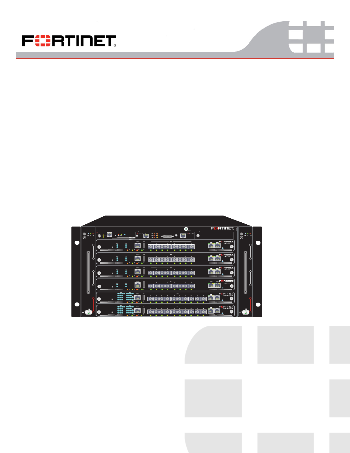
FortiGate-5060
Chassis Guide
FAN TR AY
1
SM1 SAP SM2
5000SM
10/100
ETH0
Service
link/Act
ETH1
ETH0
6
5
4
3
2
1
STATUS
10/100
link/Act
Hot Swap
RESET
1
1
1
1
5060SAP
SERIAL
1
ALARM
RESET
SERIAL
2
FortiGate 5060
FILTER TOP
FAN TR AY
2
6
5
4
3
2
1
A detailed guide to the FortiGate-5060 chassis. This FortiGate-5060 Chassis Guide describes FortiGate-5060 hardware
features, and how to install the FortiGate-5060 chassis.
The most recent versions of this and all FortiGate-5000 series documents are available from the FortiGate-5000 page of
the Fortinet Technical Documentation web site (http://docs.fortinet.com).
Visit http://support.fortinet.com to register your FortiGate-5060 chassis. By registering you can receive product updates,
technical support, and FortiGuard services.
FortiGate-5060 Chassis Guide
01-400-129494-20110912

Warnings and cautions
Warnings and cautions
Only trained and qualified personnel should be allowed to install or maintain
FortiGate-5000 series equipment. Read and comply with all warnings, cautions and
notices in this document.
CAUTION: Risk of Explosion if Battery is replaced by an Incorrect Type. Dispose of Used
Batteries According to the Instructions.
Caution: You should be aware of the following cautions and warnings before installing
FortiGate-5000 series hardware
• Turning off all power switches may not turn off all power to the FortiGate-5000 series
equipment. Some circuitry in the FortiGate-5000 series equipment may continue to
operate even though all power switches are off.
• FortiGate-5000 equipment must be protected by a readily accessible disconnect
device or circuit breaker that can be used for product power down emergencies.
• Many FortiGate-5000 components are hot swappable and can be installed or removed
while the power is on. But some of the procedures in this document may require power
to be turned off and completely disconnected. Follow all instructions in the procedures
in this document that describe disconnecting FortiGate-5000 series equipment from
power sources, telecommunications links and networks before installing, or removing
FortiGate-5000 series components, or performing other maintenance tasks. Failure to
follow the instructions in this document can result in personal injury or equipment
damage.
• Install FortiGate-5000 series chassis at the lower positions of a rack to avoid making
the rack top-heavy and unstable.
• Do not insert metal objects or tools into open chassis slots.
• Electrostatic discharge (ESD) can damage FortiGate-5000 series equipment. Only
perform the procedures described in this document from an ESD workstation. If no
such station is available, you can provide some ESD protection by wearing an
anti-static wrist strap and attaching it to an available ESD connector such as the ESD
sockets provided on FortiGate-5000 series chassis.
• Make sure all FortiGate-5000 series components have reliable grounding. Fortinet
recommends direct connections to the building ground.
• If you install a FortiGate-5000 series component in a closed or multi-unit rack
assembly, the operating ambient temperature of the rack environment may be greater
than room ambient. Make sure the operating ambient temperature does not exceed
Fortinet’s maximum rated ambient temperature.
• Installing FortiGate-5000 series equipment in a rack should be such that the amount of
airflow required for safe operation of the equipment is not compromised.
• FortiGate-5000 series chassis should be installed by a qualified electrician.
• FortiGate-5000 series equipment shall be installed and connected to an electrical
supply source in accordance with the applicable codes and regulations for the location
in which it is installed. Particular attention shall be paid to use of correct wire type and
size to comply with the applicable codes and regulations for the installation / location.
Connection of the supply wiring to the terminal block on the equipment may be
accomplished using Listed wire compression lugs, for example, Pressure Terminal
Connector made by Ideal Industries Inc. or equivalent which is suitable for AWG-10.
Particular attention shall be given to use of the appropriate compression tool specified
by the compression lug manufacturer, if one is specified.
• This product is only intended for use in a Restricted Access Location.
FortiGate-5060
01-400-129494-20110912 2
http://docs.fortinet.com/ • Feedback

Contents
Warnings and cautions . . . . . . . . . . . . . . . . . . . . . . . . . . . . . . . . . . 2
FortiGate-5060 chassis 7
FortiGate-5060 front panel . . . . . . . . . . . . . . . . . . . . . . . . . . . . . . . . 8
FortiGate-5060 chassis back panel. . . . . . . . . . . . . . . . . . . . . . . . . . . . 9
Physical description of the FortiGate-5060 chassis . . . . . . . . . . . . . . . . . . 10
FortiGate-5060 shelf managers . . . . . . . . . . . . . . . . . . . . . . . . . . . . 10
Using the shelf manager CLI . . . . . . . . . . . . . . . . . . . . . . . . . . . . 11
Shelf Manager fan and power control . . . . . . . . . . . . . . . . . . . . . . . 12
FortiGate-5060 shelf alarm panel. . . . . . . . . . . . . . . . . . . . . . . . . . . . 12
Shelf alarm panel telco alarms . . . . . . . . . . . . . . . . . . . . . . . . . . . 14
Air filter . . . . . . . . . . . . . . . . . . . . . . . . . . . . . . . . . . . . . . . . . 15
Cooling fan trays . . . . . . . . . . . . . . . . . . . . . . . . . . . . . . . . . . . . 16
Power connection and configuration 17
About data center DC power . . . . . . . . . . . . . . . . . . . . . . . . . . . . . . 17
Connecting the FortiGate-5060 chassis to DC power and data center ground. . . . . 17
Connecting a FortiGate-5060 PEM to DC power . . . . . . . . . . . . . . . . . . . . 18
Connecting the FortiGate-5060 chassis to data center ground. . . . . . . . . . . . . 19
Connecting the FortiGate-5060 chassis to AC power using a FortiGate
power converter shelf. . . . . . . . . . . . . . . . . . . . . . . . . . . . . . . . . . 20
Turning on FortiGate-5060 chassis power . . . . . . . . . . . . . . . . . . . . . . . 20
FortiGate-5060 hardware procedures 23
Mounting the FortiGate-5060 chassis . . . . . . . . . . . . . . . . . . . . . . . . . 23
Air flow . . . . . . . . . . . . . . . . . . . . . . . . . . . . . . . . . . . . . . . 23
Inserting 5000 series boards and RTM modules into a FortiGate-5060 chassis . . . . 23
Using FortiSwitch-5003A boards for backplane communication . . . . . . . . . . . . 24
FortiGate-5060 Chassis Guide
01-400-129494-20110912 3
http://docs.fortinet.com/ • Feedback

Contents
Using the shelf manager CLI 27
Connecting to the shelf manager CLI using a serial port . . . . . . . . . . . . . . . . 27
Connecting to the shelf manager CLI . . . . . . . . . . . . . . . . . . . . . . . 28
Changing the shelf manager root account password . . . . . . . . . . . . . . . 28
The shelf manager command line interface agent (CLIA) . . . . . . . . . . . . . 29
Using CLIA interactive mode . . . . . . . . . . . . . . . . . . . . . . . . . . . . 29
IPMB addresses, logical and physical slot numbers, and FRU ids . . . . . . . . . . . 30
Basic shelf manager CLI Commands. . . . . . . . . . . . . . . . . . . . . . . . . . 31
Change IP address of the primary Shelf Manager . . . . . . . . . . . . . . . . . 31
Display the shelf manager firmware version . . . . . . . . . . . . . . . . . . . . 31
List all FRUs in the chassis. . . . . . . . . . . . . . . . . . . . . . . . . . . . . 31
List all sensors on a FRU. . . . . . . . . . . . . . . . . . . . . . . . . . . . . . 31
List only sensors that are outside of established thresholds . . . . . . . . . . . . 31
Display sensor data for a FRU . . . . . . . . . . . . . . . . . . . . . . . . . . . 31
Display the FRU information for a FRU . . . . . . . . . . . . . . . . . . . . . . 31
Change the speed for a fan tray . . . . . . . . . . . . . . . . . . . . . . . . . . 31
Display the contents of the system event log (sel) . . . . . . . . . . . . . . . . . 31
Clear the system event log (sel) . . . . . . . . . . . . . . . . . . . . . . . . . . 31
Changing the shelf manager IP address and default gateway . . . . . . . . . . . . . 32
Sensor types . . . . . . . . . . . . . . . . . . . . . . . . . . . . . . . . . . . . . . 33
activate/deactivate . . . . . . . . . . . . . . . . . . . . . . . . . . . . . . . . . . . 33
alarm . . . . . . . . . . . . . . . . . . . . . . . . . . . . . . . . . . . . . . . . . . 34
Clearing alarms. . . . . . . . . . . . . . . . . . . . . . . . . . . . . . . . . . . 34
Setting alarm output . . . . . . . . . . . . . . . . . . . . . . . . . . . . . . . . 35
board . . . . . . . . . . . . . . . . . . . . . . . . . . . . . . . . . . . . . . . . . . 35
Viewing information about a board . . . . . . . . . . . . . . . . . . . . . . . . . 35
clia . . . . . . . . . . . . . . . . . . . . . . . . . . . . . . . . . . . . . . . . . . . 36
exit/quit . . . . . . . . . . . . . . . . . . . . . . . . . . . . . . . . . . . . . . . . . 36
fans . . . . . . . . . . . . . . . . . . . . . . . . . . . . . . . . . . . . . . . . . . . 36
fru . . . . . . . . . . . . . . . . . . . . . . . . . . . . . . . . . . . . . . . . . . . . 37
Display information for all FRUs . . . . . . . . . . . . . . . . . . . . . . . . . . 37
Display information for a specific FRU . . . . . . . . . . . . . . . . . . . . . . . 38
fruinfo . . . . . . . . . . . . . . . . . . . . . . . . . . . . . . . . . . . . . . . . . . 38
getlanconfig. . . . . . . . . . . . . . . . . . . . . . . . . . . . . . . . . . . . . . . 40
Displaying all configuration parameters for a channel . . . . . . . . . . . . . . . 40
Displaying specific parameters for a channel . . . . . . . . . . . . . . . . . . . 41
getthreshold/threshold . . . . . . . . . . . . . . . . . . . . . . . . . . . . . . . . . 41
Display threshold sensor values for a physical slot . . . . . . . . . . . . . . . . 42
Display threshold sensor values for a specific sensor . . . . . . . . . . . . . . . 45
FortiGate-5060 Chassis Guide
4 01-400-129494-20110912
http://docs.fortinet.com/ • Feedback

Contents
help . . . . . . . . . . . . . . . . . . . . . . . . . . . . . . . . . . . . . . . . . . . 45
Displaying more information about a command . . . . . . . . . . . . . . . . . . 48
minfanlevel . . . . . . . . . . . . . . . . . . . . . . . . . . . . . . . . . . . . . . . 49
sel. . . . . . . . . . . . . . . . . . . . . . . . . . . . . . . . . . . . . . . . . . . . 50
sensor . . . . . . . . . . . . . . . . . . . . . . . . . . . . . . . . . . . . . . . . . 51
sensordata . . . . . . . . . . . . . . . . . . . . . . . . . . . . . . . . . . . . . . . 52
setthreshold. . . . . . . . . . . . . . . . . . . . . . . . . . . . . . . . . . . . . . . 53
shmstatus. . . . . . . . . . . . . . . . . . . . . . . . . . . . . . . . . . . . . . . . 54
showunhealthy . . . . . . . . . . . . . . . . . . . . . . . . . . . . . . . . . . . . . 55
switchover . . . . . . . . . . . . . . . . . . . . . . . . . . . . . . . . . . . . . . . 55
terminate . . . . . . . . . . . . . . . . . . . . . . . . . . . . . . . . . . . . . . . . 55
user . . . . . . . . . . . . . . . . . . . . . . . . . . . . . . . . . . . . . . . . . . . 56
Display all user accounts . . . . . . . . . . . . . . . . . . . . . . . . . . . . . . 56
Adding a user account . . . . . . . . . . . . . . . . . . . . . . . . . . . . . . . 56
Deleting user accounts . . . . . . . . . . . . . . . . . . . . . . . . . . . . . . . 57
Disabling and enabling user accounts . . . . . . . . . . . . . . . . . . . . . . . 57
Changing a user account user name. . . . . . . . . . . . . . . . . . . . . . . . 57
Changing a user account password . . . . . . . . . . . . . . . . . . . . . . . . 58
version . . . . . . . . . . . . . . . . . . . . . . . . . . . . . . . . . . . . . . . . . 58
Generating SNMP traps for system events. . . . . . . . . . . . . . . . . . . . . . . 58
SNMP trap details . . . . . . . . . . . . . . . . . . . . . . . . . . . . . . . . . 62
Removing and inserting a fan tray . . . . . . . . . . . . . . . . . . . . . . . . . 64
Using the chassis system event log (SEL) . . . . . . . . . . . . . . . . . . . . . . . 64
Before you begin . . . . . . . . . . . . . . . . . . . . . . . . . . . . . . . . . . 64
Chassis Design Background . . . . . . . . . . . . . . . . . . . . . . . . . . . . 64
Alarm LEDs. . . . . . . . . . . . . . . . . . . . . . . . . . . . . . . . . . . . . 65
Reading the System Event Log (SEL) . . . . . . . . . . . . . . . . . . . . . . . 66
Clearing SEL logs . . . . . . . . . . . . . . . . . . . . . . . . . . . . . . . . . 67
Example IPMC log output . . . . . . . . . . . . . . . . . . . . . . . . . . . . . 67
Example FRU log output . . . . . . . . . . . . . . . . . . . . . . . . . . . . . . 68
Example sensor log output . . . . . . . . . . . . . . . . . . . . . . . . . . . . . 69
Sample sections of SEL Output . . . . . . . . . . . . . . . . . . . . . . . . . . 77
For more information 79
Training . . . . . . . . . . . . . . . . . . . . . . . . . . . . . . . . . . . . . . . . . 79
Documentation . . . . . . . . . . . . . . . . . . . . . . . . . . . . . . . . . . . . . 79
Fortinet Tools and Documentation CD . . . . . . . . . . . . . . . . . . . . . . . 79
Fortinet Knowledge Base . . . . . . . . . . . . . . . . . . . . . . . . . . . . . 79
Comments on Fortinet technical documentation . . . . . . . . . . . . . . . . . 79
Customer service and technical support . . . . . . . . . . . . . . . . . . . . . . . . 79
FortiGate-5060 Chassis Guide
01-400-129494-20110912 5
http://docs.fortinet.com/ • Feedback

Contents
FortiGate-5060 Chassis Guide
6 01-400-129494-20110912
http://docs.fortinet.com/ • Feedback

FortiGate-5060 chassis
You can install up to six FortiGate-5000 series boards in the six slots of the FortiGate-5060
ATCA chassis. The FortiGate-5060 is a 5U 19-inch rackmount ATCA chassis that contains
two redundant hot swappable DC power entry Modules (PEMs) connect to -48 VDC Data
Center DC power. The FortiGate-5060 chassis also includes two hot swappable cooling
fan trays and a front replaceable air filter. If all six slots contain FortiGate-5001B boards,
the FortiGate-5060 chassis provides a total of 48 FortiGate 10-gigabit ethernet interfaces.
You can also install FortiSwitch-5003B boards in FortiGate-5060 chassis slots 1 and 2 to
provide base backplane communications using the dual star base backplane interface.
Base backplane communications can be used for HA heartbeat communications and for
data communications.
FortiSwitch-5003B boards can also provide fabric backplane communication using the
FortiGate-5060 fabric backplane channels. The fabric backplane is a triple replicated
3-channel full mesh 10-gigabit switch fabric.
For both base and fabric backplane communications you can install a single
FortiSwitch-5003B board in slot 1. You can add a second FortiSwitch-5003B board to
slot 2 for redundancy.
Some of the boards installed in a FortiGate-5060 chassis can be operating in a FortiGate
HA cluster and some can be operating as standalone FortiGate units. You can also
operate multiple HA clusters and standalone FortiGate units in a single FortiGate-5060
chassis. You can also use FortiSwitch-5003B boards to operate HA clusters consisting of
FortiGate-5000 series boards installed in multiple FortiGate-5000 chassis. You can also
use FortiSwitch-5003B boards for data communication between chassis and for Enhanced
Load Balancing Cluster (ELBC) configurations. You can also install FortiSwitch-5203B
boards in slots 1 and 2, add FortiGate-5001B boards to slots 3 and up and operate the
FortiGate-5060 chassis in HA over chassis mode.
The FortiGate-5060 chassis also includes six rear transition module (RTM) slots. The
FortiGate-5060 chassis supports 10-gigabit fabric channel communication if you have
installed FortiGate-5001A boards with FortiGate-RTM-XB2 or FortiGate-RTM-XD2
modules and one or two FortiSwitch-5003A or FortiSwitch-5003B boards.
The FortiGate-5060 chassis requires -48VDC Data Center DC power. If DC power is not
available you can install a FortiGate power converter shelf and power supplies (purchased
separately).
This chapter describes the FortiGate-5060 chassis and includes the following sections:
• FortiGate-5060 front panel
• FortiGate-5060 chassis back panel
• Physical description of the FortiGate-5060 chassis
• FortiGate-5060 shelf managers
• FortiGate-5060 shelf alarm panel
• Air filter
• Cooling fan trays
FortiGate-5060 Chassis Guide
01-400-129494-20110912 7
http://docs.fortinet.com/ • Feedback
FortiGate-5060 front panel FortiGate-5060 chassis
FortiGate-5060 front panel
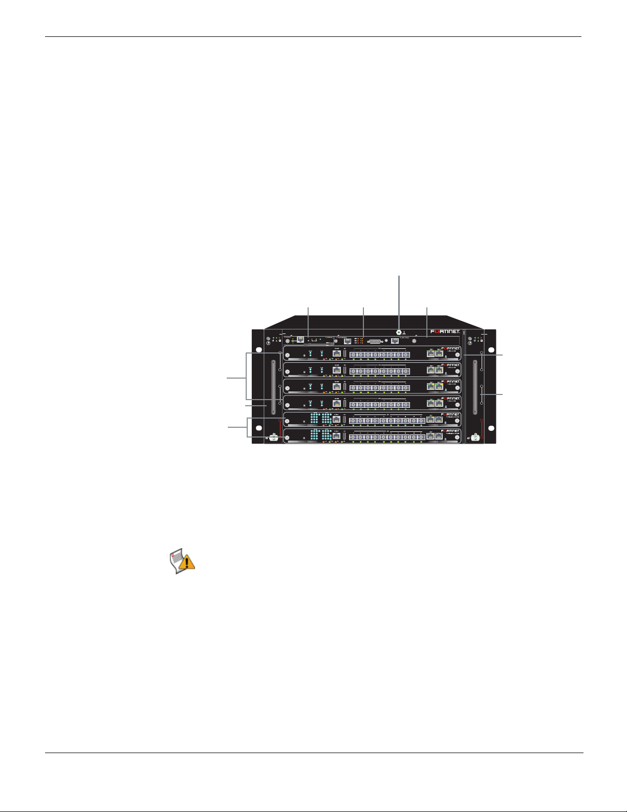
Figure 1 shows the front of a FortiGate-5060 chassis. Two FortiSwitch-5003B boards are
installed in slots 1 and 2. Four FortiGate-5001B boards are installed in slots 3, 4, 5, and 6.
The FortiGate-5060 primary Shelf Manager and the Shelf Alarm Panel (SAP) are also
visible. The factory installed shelf alarm panel displays alarms, provides a telco alarm
interface, and also provides serial connections to the shelf managers. The factory installed
primary shelf manager provides power allocation, cooling, alarms, and shelf status for the
FortiGate-5060 chassis. You can also install a secondary shelf manager as a backup for
the primary shelf manager. For more information about these components, see
“FortiGate-5060 shelf alarm panel” on page 12 and “FortiGate-5060 shelf managers” on
page 10.
Figure 1: FortiGate-5060 front panel with FortiGate-5001B and FortiSwitch-5003B boards
installed
ESD socket
Primary
Shelf Manager
(SM 1)
Shelf Alarm
Panel (SAP)
Secondary
Shelf Manager
(SM 2) Slot Cover
FortiGate-5001B
boards, slots 3,
4, 5, and 6
Hot-swappable
cooling fan tray 1
FortiSwitch-5003B
boards
slots 1 and 2
FAN TRAY
1
SM1 SAP SM2
5000SM
10/100
ETH0
Service
link/Act
ETH1
STATUS
10/100
RESET
ETH0
link/Act
6
5
4
3
2
1
5060SAP
Hot Swap
SERIAL
1
1
1
1
1
ALARM
SERIAL
RESET
FortiGate 5060
2
FAN TRAY
2
Front-replacable
6
FILTER TOP
5
4
3
2
1
air filter
Hot-swappable
cooling fan tray 2
Also visible on the front of the FortiGate-5060 chassis:
• The location of the two hot-swappable FortiGate-5060 cooling fan trays.
• The location of the front-replaceable air filter.
• The Electrostatic discharge (ESD) socket, used for connecting an ESD wrist band
when working with the chassis.
Caution: Do not operate the FortiGate-5060 chassis with open slots on the front panel. For
optimum cooling performance and safety, the chassis slots must contain a FortiGate-5000
series board or an air baffle slot filler. For the same reason, both cooling fan trays and the
air filter should be installed while operating the chassis. As well both PEMs must be
installed in the back of the chassis.
FortiGate-5060 Chassis Guide
8 01-400-129494-20110912
http://docs.fortinet.com/ • Feedback
FortiGate-5060 chassis FortiGate-5060 chassis back panel
FortiGate-5060 chassis back panel
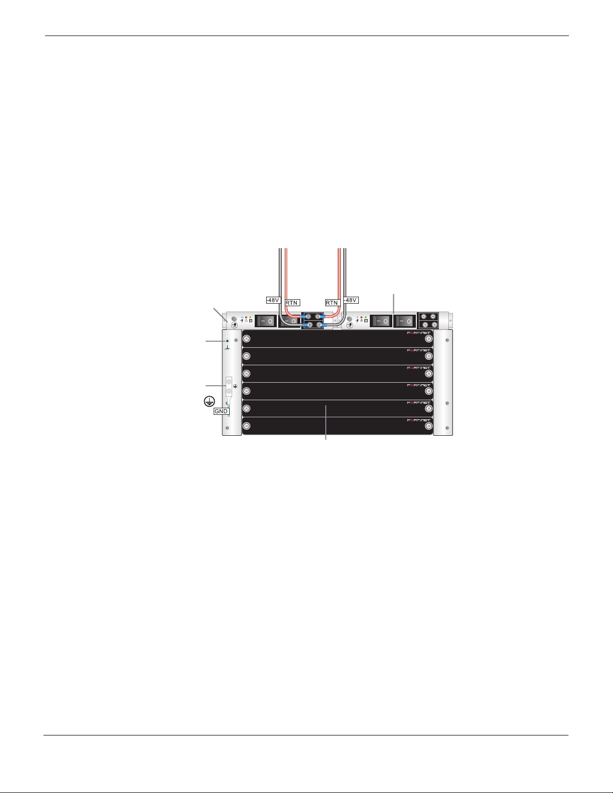
Figure 2 shows the back of a FortiGate-5060 chassis. The FortiGate-5060 chassis back
panel includes two redundant -48V to - 60 VDC power entry modules (PEMs) labelled
PEM A and PEM B. Fortinet ships the FortiGate-5060 chassis with PEM A and B installed.
The PEMs provide redundant DC power connections for the FortiGate-5060 chassis and
distribute DC power to the chassis slots and to the fan trays.
If you require redundant power you should connect both PEMs to DC power. If redundant
power is not required, you can connect PEM A or PEM B. Each PEM includes two power
terminals, one for connecting to -48V/-60 VDC and one for connecting to RTN. Use twohole lugs to connect the power terminals to DC power. Figure 2 shows the wiring required
to connect PEM B to a DC power source.
Figure 2: FortiGate-5060 chassis back panel (shows PEM B connected to DC power source)
Power
-48V/-60 VDC
nom (black)
(lower)
RTN
(red)
(upper)
Power
Entry Module
(PEM) A
Entry Module
(PEM) B
ESD
PEM
Branch 1 Branch 2
-48/-60 V
RTN
PEM
Branch 1 Branch 2
RTN
-48/-60 V
PEM APEM B
socket
Chassis
Ground
Connector
(green)
RTM Air Baffle slot covers
The back panel includes the FortiGate-5060 chassis ground connector which must be
connected to Data Center ground. The FortiGate-5060 chassis also includes an ESD
socket on the back panel.
For detailed information about connecting power to the FortiGate-5060 chassis, see
“Connecting the FortiGate-5060 chassis to DC power and data center ground” on page 17
or “Connecting the FortiGate-5060 chassis to AC power using a FortiGate power
converter shelf” on page 20.
The back panel also contains 6 RTM slots numbered to correspond to the front panel
slots. The RTM slots are available for FortiGate-5000 RTM modules such as the
FortiGate-RTM-XB2 module or the FortiGate-RTM-XD2 module. When the
FortiGate-5060 chassis is shipped, these slots are covered by RTM air baffle slot covers.
FortiGate-5060 Chassis Guide
01-400-129494-20110912 9
http://docs.fortinet.com/ • Feedback
Physical description of the FortiGate-5060 chassis FortiGate-5060 chassis
Physical description of the FortiGate-5060 chassis
The FortiGate-5060 chassis is a 5U chassis that can be installed in a standard 19-inch
rack. Table 1 describes the physical characteristics of the FortiGate-5060 chassis.
Table 1: FortiGate-5060 chassis physical description
Dimensions 8.75 x 17 x 18.9 in. (22.2 x 43.2 x 48cm) (H x W x D) The
Shipping weight completely
assembled
with packaging
Chassis weight completely
assembled with shelf manager
and air baffles (5 front and 6
RTM)
Torque Rating 1.2 N m to 1.5 N m
Operating environment Temperature (long term): 41 to 104°F (+5 to 40°C)
Power consumption Maximum: 350 W (Power consumed by an empty chassis with
Power input 2x redundant -40.5 VDC to -60 VDC, 45 A total per PEM
Overcurrent Protection 30 A Fused Switches on PEMs
Cooling Capacity Front Boards: 300 W per board
Protected Earth Test EN60950-1, test current 25 A, resistance <100mOhm
Hipot Test EN60950-1, 1000 V
depth is from the fan tray handles on the front panel to the
connectors on the PEMs on the back panel.)
65.7 lb. (30 kg)
50.7 lb. (23 kg)
Temperature (short term): 23 to 131°F (-5 to 45°C)
Relative humidity: 5 to 85% (Non-condensing)
two fan trays, 2 shelf managers, one shelf alarm panel and 2
PEMs installed and operating with the fans running at full
speed.)
RTM: 30 W per module
FortiGate-5060 shelf managers
The FortiGate-5060 chassis includes one or two redundant hot-swappable shelf
managers, located in the dedicated shelf manager slots near the top of the FortiGate-5060
front panel. The primary shelf manager is installed on the left (SM 1) the secondary shelf
manager (if present) is installed on the right (SM 2). The secondary shelf manager is
optional.
The shelf managers support redundant operation with automatic switchover. If both shelf
managers are operating normally, one acts as the active shelf manager and the other as
the standby. Usually the primary shelf manager would be the active shelf manager and the
secondary shelf manager would be the standby shelf manager. The shelf managers
monitor each other and either can trigger a switchover if necessary. The active shelf
manager performs all shelf manager functions. If the active shelf manager fails or is
removed, the standby shelf manager takes over all shelf manager functions.
The FortiGate-5060 shelf managers control chassis power allocation, monitor chassis
operating parameters, monitor and control chassis cooling, and can signal alarms if the
chassis encounters problems. All FortiGate-5000 modules installed in the chassis
communicate with the shelf managers.
FortiGate-5060 Chassis Guide
10 01-400-129494-20110912
http://docs.fortinet.com/ • Feedback
FortiGate-5060 chassis FortiGate-5060 shelf managers
The FortiGate-5060 shelf managers are factory installed. In most cases users do not have
to install or configure the shelf managers.
Each shelf manager has two ethernet interfaces (ETH 0 and ETH 1). You can connect to
ETH 0 from the shelf manager front panel. ETH 1 connects to the FortiGate-5060
backplane.
The shelf managers detect alarm conditions and communicate alarm signals to the
FortiGate-5060 shelf alarm panel. The shelf alarm panel also contains serial interfaces for
connecting to the shelf manager’s console ports.
The shelf managers are hot swappable. You can remove a shelf manager by opening the
extraction lever until the hot swap LED starts blinking. When the hot swap LED turns solid
blue you can remove the shelf manager from the FortiGate-5060 chassis.
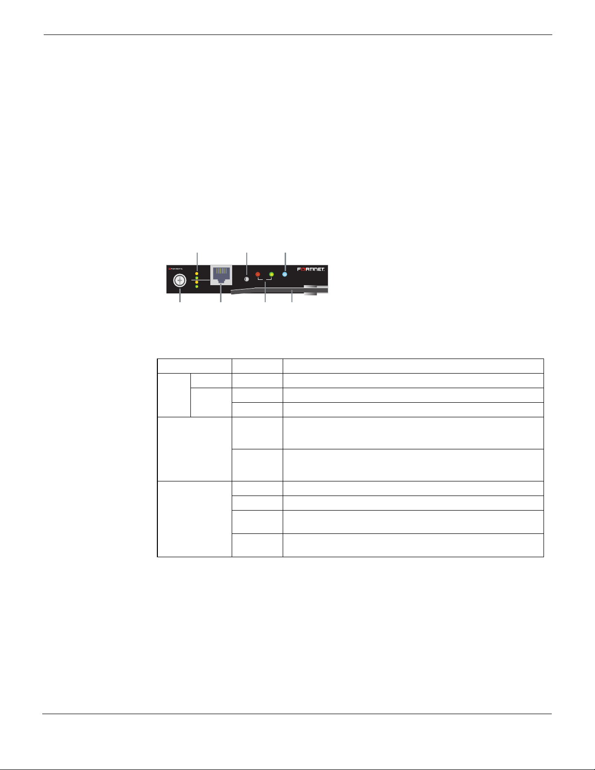
Figure 3: FortiGate-5060 shelf manager front panel
RESET
Status
LEDs
Hot Swap
LED
STATUS
Handle
Hot Swap
ETH 0 and 1 network
activity LEDs
5000SM
10/100
link/Act
ETH1
10/100
ETH0
link/Act
Retention
Screw
ETH0
10/100/1000
base-T Ethernet
Reset
Button
ETH0
Service
Table 2: FortiGate-5060 shelf manager LEDs
LED State Description
ETH 0
ETH 1
10/100 Yellow The Ethernet interface is connected at 100 Mbps.
link/Act Green Blinking LED indicates network traffic.
Off No link.
STATUS Green This shelf manager is operating normally as the active shelf
manager. Usually the primary shelf manager operates as the
active shelf manager.
Red This shelf manager is operating normally as the backup shelf
manager. Usually the secondary shelf manager operates as the
standby shelf manager.
HOT SWAP Off The shelf manager is not ready to be removed.
Blue The shelf manager is ready to be removed.
Long blink The shelf manager is starting up after being inserted into the
chassis.
Short blink The shelf manager is shutting down in preparation for being
removed from the chassis.
Using the shelf manager CLI
You can use the shelf manager command line interface (CLI) to communicate with the
intelligent management controllers of the chassis, with boards in the chassis, and with the
shelf manager itself. The CLI is an IPMI-based set of commands that can be accessed
directly or through a higher-level management application or a script. Using the CLI, you
can access information about the current state of the chassis including current board
population, current sensor values, threshold settings, recent events, and overall chassis
health.
To get started using the shelf manager CLI, see “Using the shelf manager CLI” on
page 27.
FortiGate-5060 Chassis Guide
01-400-129494-20110912 11
http://docs.fortinet.com/ • Feedback
FortiGate-5060 shelf alarm panel FortiGate-5060 chassis
Shelf Manager fan and power control
The FortiGate-5060 shelf managers monitor the internal temperature of the
FortiGate-5060 chassis and adjust the operating speed of the FortiGate-5060 chassis
cooling fans as required.
When the chassis is first powered on all cooling fans run at full speed. Once the shelf
manager is up and running, the shelf manager reduces cooling fan speeds to maintain an
optimum temperature in the chassis. If shelf managers are not installed or not operating
correctly the FortiGate-5060 chassis cooling fans always operate at full speed.
FortiGate-5060 shelf alarm panel
The FortiGate-5060 shelf alarm panel (SAP), located at the top of the FortiGate-5060 front
panel, provides LED indicators of FortiGate-5060 alarms, a telco alarm connector, an
alarm LED reset button, and console access to the FortiGate-5060 shelf managers. The
LED alarm indicators include critical, major, and minor alarms as well as three user
defined alarms.
The alarm LED reset button (RESET) on the shelf alarm panel activates the Alarm Cutoff
(ACO) state. When ACO is activated, the active alarm LEDs blink and all of the alarm
relays are deactivated.
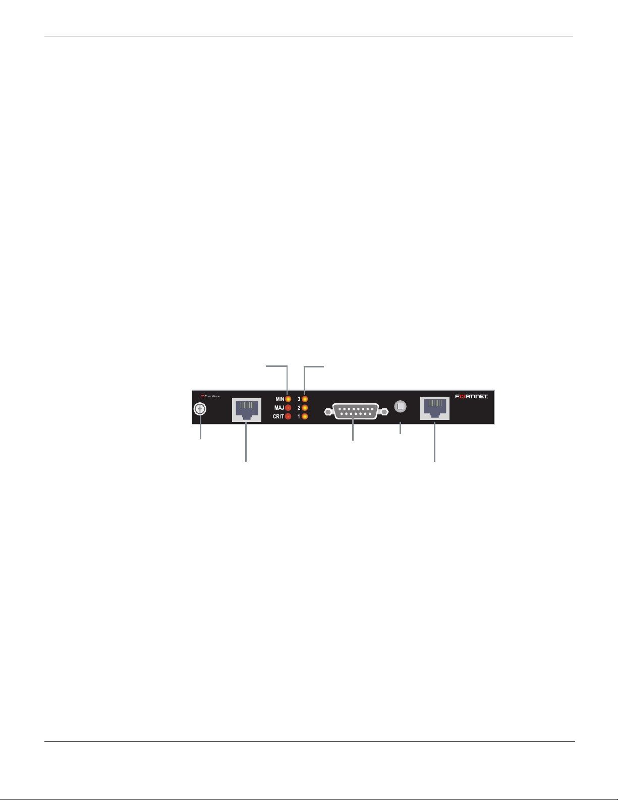
Figure 4: FortiGate-5060 shelf alarm panel front panel
Minor Alarm (MIN) (Amber)
Major Alarm (MAJ) (Red)
Critical Alarm (CRT) (Red)
5000SAP
SERIAL
1
Retention
Screw
SERIAL 1 (Primary
Shelf Manager)
User 3 Alarm (Amber)
User 2 Alarm (Amber)
User 1 Alarm (Amber)
ALARM
Telco Alarm
Interface
LED Reset
RESET
Alarm
Button
SERIAL 2 (Secondary
Shelf Manager)
SERIAL
2
FortiGate-5060 Chassis Guide
12 01-400-129494-20110912
http://docs.fortinet.com/ • Feedback
FortiGate-5060 chassis FortiGate-5060 shelf alarm panel
Table 3: FortiGate-5060 shelf alarm panel LEDs
LED State Description
CRT
(critical)
MAJ (major) Off Normal operation.
MIN (minor) Off Normal operation.
USER3
USER2
USER1
Off Normal operation.
Red Indicates a critical alarm.
Blinking
Red
Red Indicates a major alarm.
Blinking
Red
Amber Indicates a minor alarm.
Blinking
Amber
Off Normal operation
Amber Indicates a user-definable alarm.
Blinking
Amber
Alarm cutoff (ACO) activated by pressing the alarm LED reset button.
Alarm cutoff (ACO) activated by pressing the alarm LED reset button.
Alarm cutoff (ACO) activated by pressing the alarm LED reset button.
Alarm cutoff (ACO) activated by pressing the alarm LED reset button.
Table 4: FortiGate-5060 shelf alarm panel connectors
Connector Type Speed Protocol Description
SERIAL 1 RJ-45 9600 bps,
SERIAL 2 RJ-45 9600 bps,
ALARM micro
DB-15
male
8/N/1
8/N/1
N/A Telco
RS-232
serial
RS-232
serial
Form-c
Serial connection to the primary shelf manager
command line interface.
Serial connection to the secondary shelf
manager command line interface.
The external dry relay Telco alarm interface
(48VDC) provides Telco form-c relay
connections for minor, major and critical power
faults. The cable required to connect to the
alarm interface is not supplied by Fortinet.
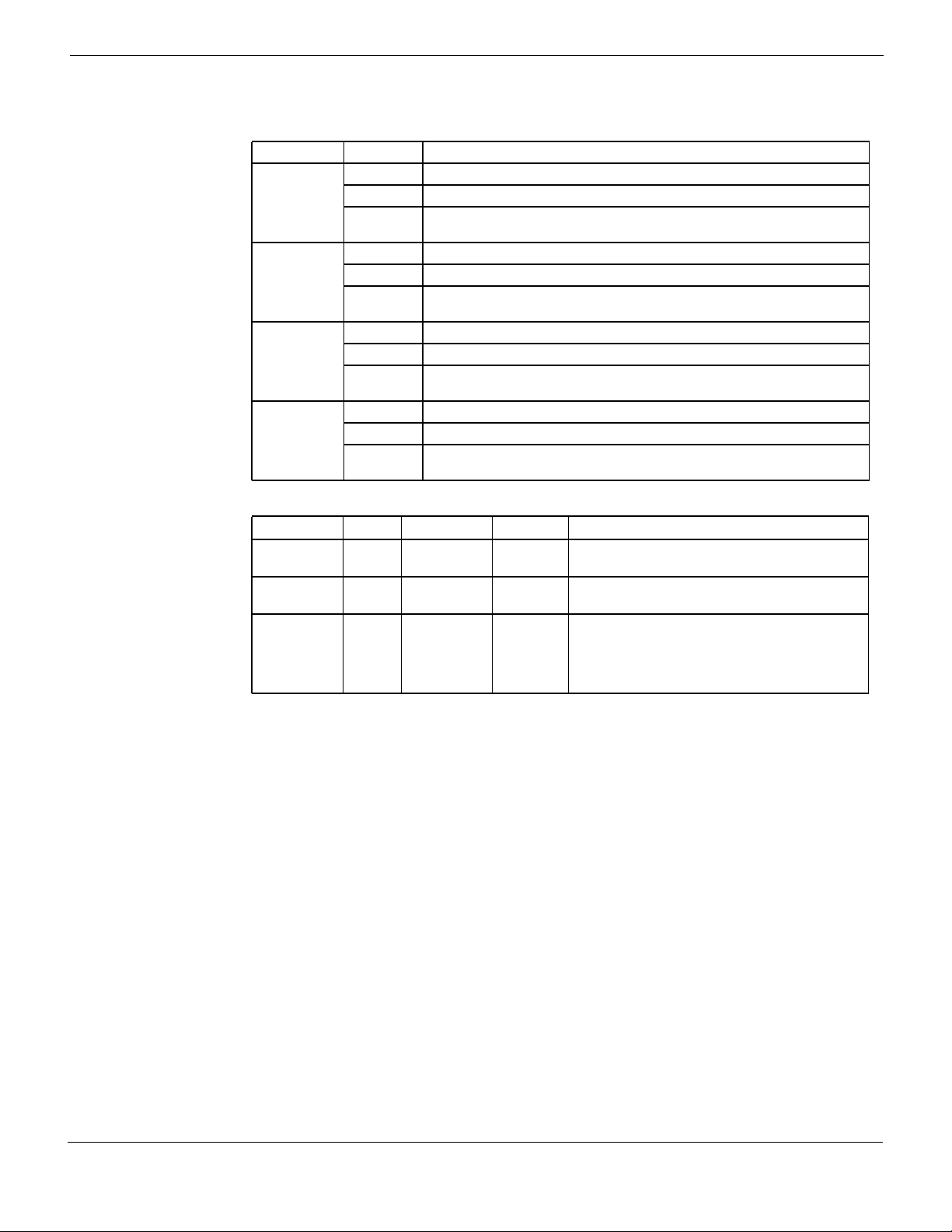
Figure 5 shows the connections between the primary and secondary shelf managers and
the shelf alarm panel.
FortiGate-5060 Chassis Guide
01-400-129494-20110912 13
http://docs.fortinet.com/ • Feedback
FortiGate-5060 shelf alarm panel FortiGate-5060 chassis
Figure 5: Connections between the shelf managers and the shelf alarm panel
5000SAP
SERIAL
1
e
c
a
I²C-Switch
f
re
PCA9545
tn
Ielo
s
n
o
Clai
r
e
S
ShMM-500
Secondary Shelf Manager (Left)
Shelf alarm panel telco alarms
The shelf alarm panel telco alarm interface relay circuits are capable of carrying 60 VDC
or 1 A with a max. rating of 30 VA. The shelf alarm panel accepts timed pulse inputs for
clearing minor and major alarm states. Reset is accomplished by asserting a voltage
differential from 3.3 V to 48 V for between 200 and 300 ms. The acceptance voltage range
is from 0 to 48 VDC continuous (handles up to 60 VDC at a 50% duty cycle). The current
drawn by a reset input does not exceed 12 mA.
The alarm LED reset button activates the alarm cutoff (ACO) state for major, minor, and
user-defined alarms. You cannot reset critical alarms with the alarm LED reset button.
When the ACO state is activated, active alarm LEDs blink and all of the alarm relays are
deactivated. The alarm reset button activates the ACO state but does not clear the alarm
completely.
ALARM
3HC
0HC
Buffer
LTC4300
elbanE
I²C-Switch
PCA9545
ylnO-re
sub-
tsaM
C²I
3HC
RESET
LTC4300
el
b
a
n
E
0HC
Buffer
y
l
nO-retsaM
SERIAL
2
e
cafretnIelos
noClaireS
sub-C²I
ShMM-500
Primary Shelf Manager (Right)
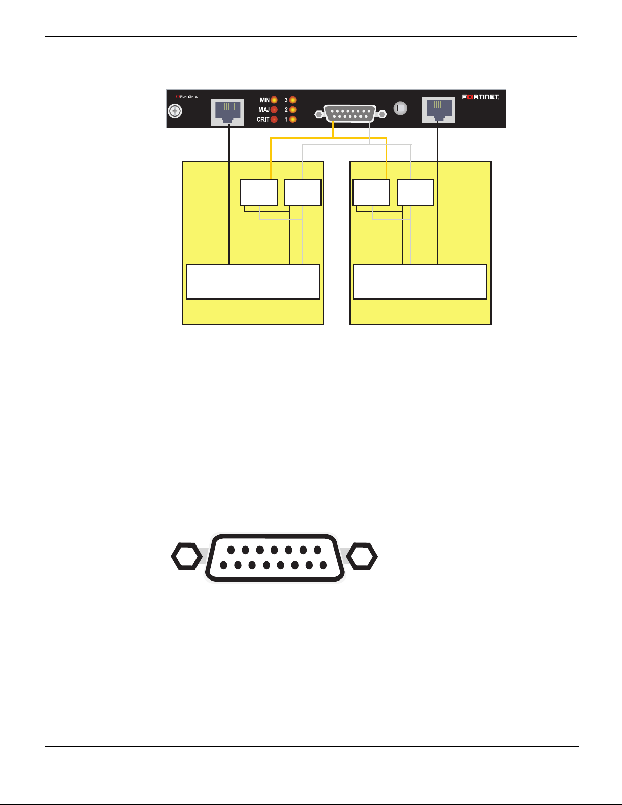
Figure 6: The telco alarm connector (DB-15 male)
915
8
14 01-400-129494-20110912
1
FortiGate-5060 Chassis Guide
http://docs.fortinet.com/ • Feedback

FortiGate-5060 chassis Air filter
Table 5: Telco alarm connector pin assignment
Pin Name Description
1 AMIR+ MinorReset+
2 AMIR- MinorReset-
3 AMAR+ MajorReset+
4 AMAR- MajorReset-
5 ACNO CriticalAlarm - NO
6 ACNC CriticalAlarm - NC
7 ACCOM CriticalAlarm - COM
8 AMINO MinorAlarm -NO
9 AMINC MinorAlarm - NC
10 AMINCOM MinorAlarm - COM
11 AMANO MajorAlarm - NO
12 AMANC MajorAlarm - NC
13 AMACOM MajorAlarm - COM
14 APRCO PwrAlarm - NO
15 APRCOM PwrAlarm - COM
Shield Shelf-GND Shelf Ground
Air filter
The FortiGate-5060 chassis includes a front replaceable air filter. The filter provides 80%
dust arrestance and meets the requirements of the Telcordia Technologies Generic
Requirements GR-78-CORE specification. The filter must be installed for the
FortiGate-5060 chassis to operate normally. If the air filter is not locked into place the air
filter presence switch causes an alarm.
Air filters should be inspected regularly. If dirty or damaged, the filter should be disposed
of and replaced.
The air filter can be removed using the air filter handle on the front of the FortiGate-5060
chassis. To install a new filter, push the new filter into the guide rails at each side of the
shelf until the filter locks into place.
FortiGate-5060 Chassis Guide
01-400-129494-20110912 15
http://docs.fortinet.com/ • Feedback
Cooling fan trays FortiGate-5060 chassis
Cooling fan trays
The FortiGate-5060 chassis contains two identical hot-swappable cooling fan trays
installed on the left and right sides of the chassis. The chassis can run indefinitely with
only one fan tray operating. The fans move air in the right side of the chassis and out the
left side.
You can remove a fan tray by pressing the hot swap button on the fan tray front panel.
When the Hot Swap LED is solid blue unlock the latch and pull the fan tray out using the
extraction handle.
Each cooling fan tray contains six radial fans for cooling the boards and modules installed
in the FortiGate-5060 chassis. Fan speeds are monitored by a tachometer signal sent
from the cooling fan trays to the shelf manager. The shelf manager regulates the fan
speed by adjusting the DC voltage supplied to the fan trays.
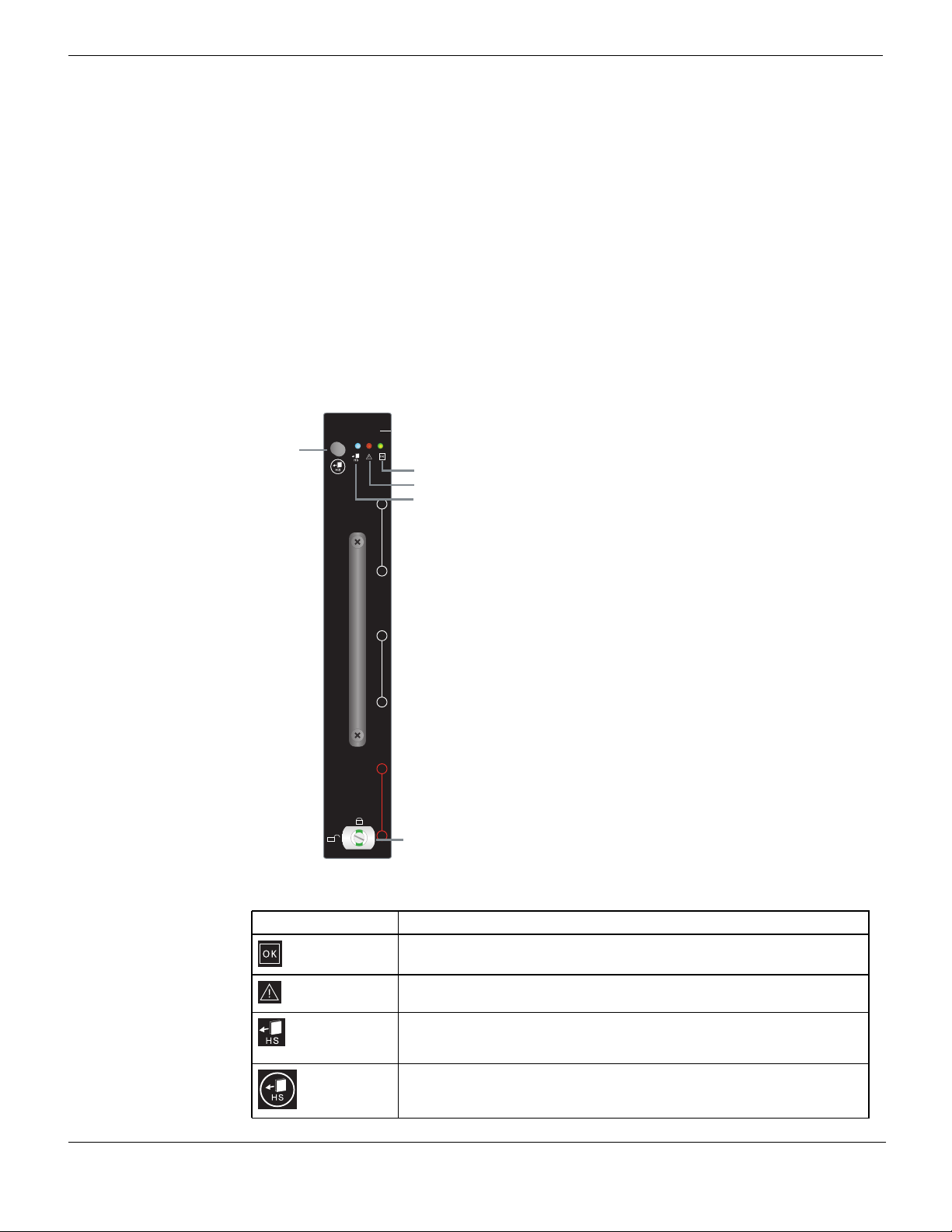
Figure 7: Cooling fan tray front panel
Hot swap
button
FAN TRAY
6
5
4
3
2
1
Latch
OK LED
Alarm LED
Hot swap LED
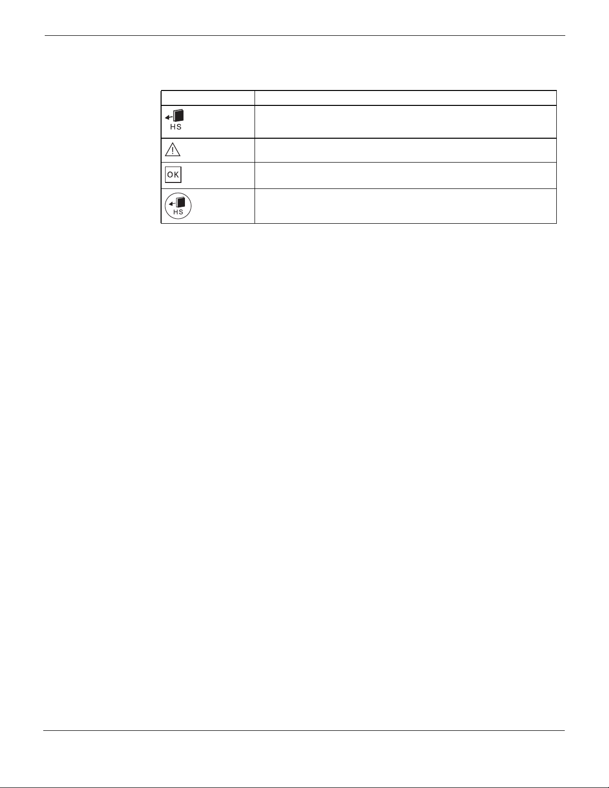
Table 6: FortiGate-5060 fan tray LEDs and controls
LED/Control Description
OK (operate)
Green when the fan tray is powered and operating normally.
LED
Alarm LED Normally off. Turns red when there is a problem with the fan tray.
HS (hot swap)
LED
HS (hot
swap) button
Normally off. Blinking blue indicates that the fan tray is entering the hot
swap mode. Solid blue indicates that the fan tray is in hot swap mode and
can be removed from the chassis.
Press the HS button to enter hot swap mode. When the HS LED becomes
solid blue you can remove the fan tray from the chassis.
FortiGate-5060 Chassis Guide
16 01-400-129494-20110912
http://docs.fortinet.com/ • Feedback

Power connection and configuration
This chapter describes how to connect DC power to a FortiGate-5060 chassis.
If main DC power supplied by the data center in which the FortiGate-5060 chassis is to be
installed is not available, you can use a FortiGate power converter shelf to convert AC to
DC to supply DC power to the FortiGate-5060 chassis.
This chapter describes:
• About data center DC power
• Connecting the FortiGate-5060 chassis to DC power and data center ground
• Connecting a FortiGate-5060 PEM to DC power
• Connecting the FortiGate-5060 chassis to data center ground
• Connecting the FortiGate-5060 chassis to AC power using a FortiGate power
converter shelf
• Turning on FortiGate-5060 chassis power
About data center DC power
The FortiGate-5060 chassis is designed to be installed in a data center or similar location
that has available -48VDC power fed from a 30A listed circuit breaker (also called battery
power or main DC power). Fortinet expects that most FortiGate-5060 customers will be
installing their chassis in a data center or similar location that is already equipped with a
-48VDC power system fed from a 30A listed circuit breaker that provides power to existing
networking or telecom equipment. The FortiGate-5060 chassis is designed to be
connected directly to this DC power system.
In this document, data center DC power refers to a -48VDC power system that is already
available at the location at which the FortiGate-5060 chassis is being installed.
Connecting the FortiGate-5060 chassis to DC power and data center ground
Connect the FortiGate-5060 chassis to r DC power using the redundant -48V to - 60 VDC
power entry modules (PEMs) on the FortiGate-5060 back panel labelled PEM A and
PEM B. The specified voltage range of the PEMs is -40.5 VDC to -60 VDC. The chassis
ships with both PEM A and B installed. The PEMs provide redundant DC power
connections for the FortiGate-5060 chassis and distribute DC power to the chassis slots
and to the fan trays.
Each FortiGate-5060 PEM includes two connectors for two power terminals that connect
power to different power zones in the FortiGate-5060 chassis. In the PEM, each power
terminal is protected by a 30A fused switch. The power zones are connected together and
should be connected to a single -48VDC power source with a 30A listed circuit breaker.
Each power zone supplies power to different FortiGate-5060 slots and cooling fan trays.
You should always connect both power zones.
FortiGate-5060 Chassis Guide
01-400-129494-20110912 17
http://docs.fortinet.com/ • Feedback
Connecting a FortiGate-5060 PEM to DC power Power connection and configuration
To connect the FortiGate-5060 PEMs to data center DC power you must use power
connectors that comply with the local electrical wiring code and the requirements of the
facility in which you are installing the FortiGate-5060 chassis.
Fortinet supplies two 3-ft. power cables with AWG-10 stranded wires and ring terminals:
Black for -48VDC and red for RTN. These cables should only be used to connect the
FortiGate-5060 PEMs to a FortiGate power convertor shelf if purchased with your
FortiGate-5060 chassis. If the power cable length needs to be longer than 3 ft., higher
gauge wires should be used.
Green AWG-6 wires are recommended for ground connections (not supplied with the
chassis).
If you are connecting both PEMs the -48VDC and RTN terminals on PEM A and PEM B
must be wired symmetrically. This means that the connections must be the same to both
PEMs.
FortiGate-5060 PEMs are hot-swappable, which means you can remove and replace a
defective PEM while the system is operating (assuming that the FortiGate-5060 system
has both PEMs connected for redundancy). It is not necessary to notify the software or
reset the system power. You can add, remove, or replace a second PEM without
interrupting FortiGate-5060 operation.
Connecting a FortiGate-5060 PEM to DC power
The following procedure describes how to connect power to PEM A. You can repeat this
procedure to connect PEM B.
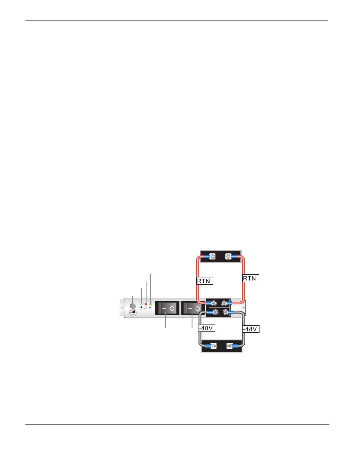
Figure 8: Connecting a FortiGate-5060 PEM to DC power
DC Power Source
RTN connector
Hot swap LED
Alarm LED
OK LED
Hot swap button
PEM
Branch 1 Branch 2
-48/-60 V
Power Switches
RTN (positive)
red to power
source RTN
RTN
-48V/-60 VDC
black to power
source -48VDC
DC Power Source
-48VDC
connector
FortiGate-5060 Chassis Guide
18 01-400-129494-20110912
http://docs.fortinet.com/ • Feedback
Power connection and configuration Connecting the FortiGate-5060 chassis to data center ground
Table 7: FortiGate-5060 PEM LEDs and controls
LED/Control Description
HS (hot swap)
LED
Alarm LED Normally off. Turns red when there is a problem with the power source, or if
OK (operate)
LED
HS (hot
swap) button
Normally off. Blinking blue indicates that the PEM is entering the hot swap
mode. Solid Blue indicates that the PEM is in hot swap mode and can be
removed from the chassis.
one or more of the 8 PEM fuses are blown or missing.
Green when the PEM is powered and operating normally.
Press the HS button to enter hot swap mode. When the HS LED becomes
solid blue you can remove the PEM from the chassis.
You need the following tools and equipment to connect a FortiGate-5060 PEM to data
center DC power:
• A hex socket wrench is recommended for loosening and tightening the nuts on the
PEM power terminals.
• An electrostatic discharge (ESD) preventive wrist strap with connection cord.
• Two black AWG-10 stranded wires labelled -48V with attached Listed closed loop
single hole lugs with insulating boot suitable for minimum 10AWG copper wire, such as
3M model MH10-14RX.
• Two red AWG-10 stranded wires labelled RTN with attached Listed closed loop single
hole lugs with insulating boot suitable for minimum 10AWG copper wire, such as 3M
model MH10-14RX.
To connect a FortiGate-5060 PEM to data center DC power
1 Attach the ESD wrist strap to your wrist and to an ESD socket or to a bare metal
surface on the chassis or frame.
2 Turn off both power switches on the PEM.
3 Remove the clear plastic cover from the PEM power connectors.
4 Connect the DC power wires (see Figure 8):
• Connect two black -48V power wires from the DC power source to the connectors
on the FortiGate-5060 PEM labeled -48V/-60 V (the lower connectors on the PEM).
• Connect two red RTN return wires from data center RTN to the connectors on the
FortiGate-5060 PEM labeled RTN (the upper connectors on the PEM).
5 Make sure the power wires are secured using tie wraps if required.
6 If required, label the black wire -48V.
7 If required, label the red wire RTN.
8 Turn on the PEM switches.
Connecting the FortiGate-5060 chassis to data center ground
The FortiGate-5060 chassis includes a ground terminal on the lower left side of the
FortiGate-5060 back panel (see Figure 2 on page 9). The Shelf ground terminal provides
two threads (M6) with a 15.88 mm (5/8“) spacing between thread centers to connect a
two-hole lug. This connector must be connected to data center ground.
You need the following tools and equipment to connect the FortiGate-5060 chassis to
ground:
FortiGate-5060 Chassis Guide
01-400-129494-20110912 19
http://docs.fortinet.com/ • Feedback
Connecting the FortiGate-5060 chassis to AC power using a FortiGate power converter shelf Power connection and configuration
• A number 2 Phillips screwdriver.
• An electrostatic discharge (ESD) preventive wrist strap with connection cord.
• One green AWG-6 stranded wire with M6 two-hole terminal lug with 45° angle tongue
with a 15.88 mm (5/8“) spacing between hole centers.
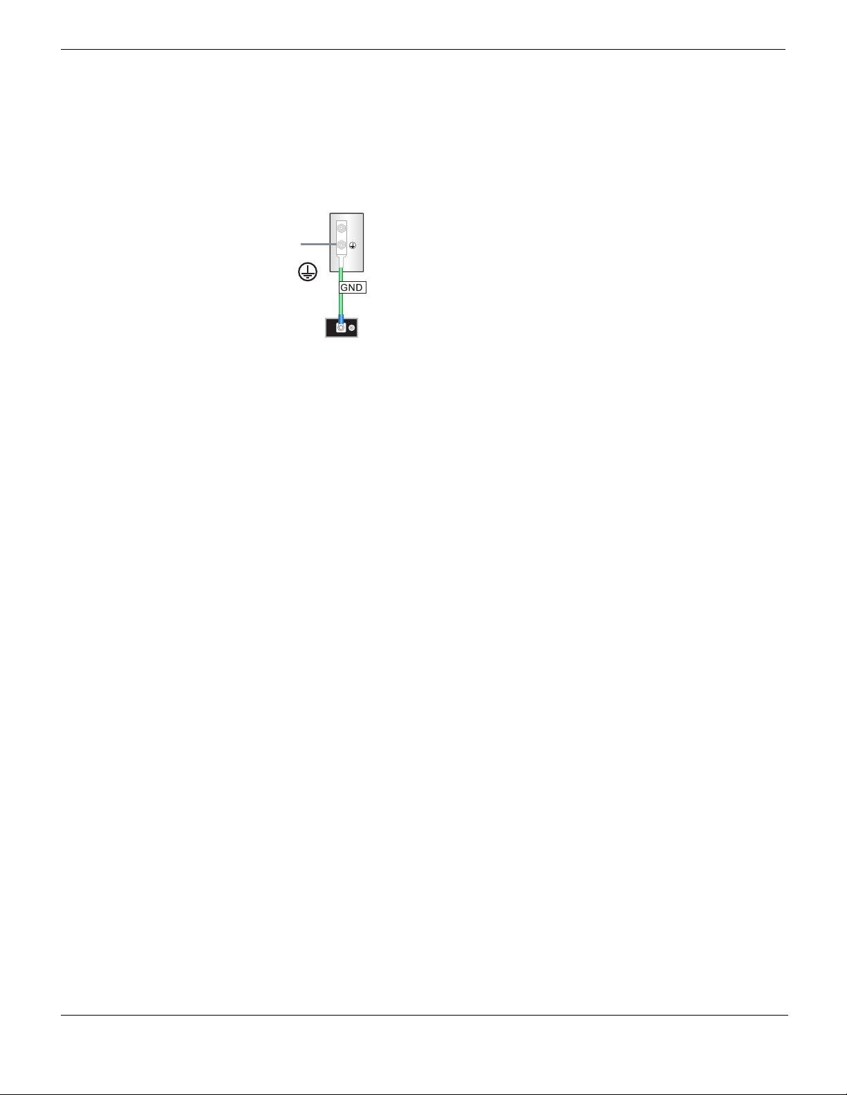
Figure 9: Connecting a FortiGate-5060 chassis to data center ground
Chassis
Ground
Connector
(green)
Data Center
ground
connector
To connect the FortiGate-5060 chassis to data center ground
1 Attach the ESD wrist strap to your wrist and to an ESD socket or to a bare metal
surface on the chassis or frame.
2 Connect the green ground wire from the data center ground to the ground connector on
the FortiGate-5060 chassis (see Figure 9).
3 Secure the ground wire to the chassis.
4 Optionally label the wire GND.
FortiGate-5060
Ground
Connector
(green)
(Central office
ground system)
Connecting the FortiGate-5060 chassis to AC power using a FortiGate power converter shelf
If data center DC power is not available, you can use a Fortinet-supplied power converter
shelf with hot swappable power supplies to convert AC power to DC power. FortiGate
power converter shelves and power supplies are not supplied with the FortiGate-5060
chassis and must be purchased separately.
As already mentioned, the FortiGate-5060 chassis ships with two 3-ft. power cables with
AWG-10 stranded wires and ring terminals: Black for -48VDC and red for RTN. These
cables should only be used to connect the FortiGate-5060 PEMs to a FortiGate power
convertor shelf if purchased with your FortiGate-5060 chassis. If the power cable length
needs to be longer than 3 ft., higher gauge wires should be used.
Turning on FortiGate-5060 chassis power
If you are using a power converter shelf, connect the power convertor shelf to AC power
and verify that it is operating correctly.
If you are using data center DC power, turn own the power to the chassis according to the
requirements of your data center DC power system.
Once the FortiGate-5060 chassis is connected to DC power you can turn on power to the
chassis by turning on the switches on the PEMs (see Figure 8 on page 18 for location of
the switches on each PEM).
FortiGate-5060 Chassis Guide
20 01-400-129494-20110912
http://docs.fortinet.com/ • Feedback

Power connection and configuration Turning on FortiGate-5060 chassis power
The FortiGate-5060 chassis powers up. If the FortiGate-5060 is operating correctly, the
OK LEDs on the PEMs and fan trays should be lit. As well, the Status LED on the
FortiGate-5060 shelf manager front panel should be lit (see Figure 3 on page 11). None of
the LEDs on the shelf alarm panel (SAP) should be lit (see Figure 4 on page 12).
When the chassis first starts up you should also hear the cooling fans operating.
In addition, if any FortiGate-5000 series modules have been installed in the chassis they
should power on and their front panel LEDs should indicate that they are operating
normally.
FortiGate-5060 Chassis Guide
01-400-129494-20110912 21
http://docs.fortinet.com/ • Feedback

Turning on FortiGate-5060 chassis power Power connection and configuration
FortiGate-5060 Chassis Guide
22 01-400-129494-20110912
http://docs.fortinet.com/ • Feedback
FortiGate-5060 hardware procedures
This chapter assumes the chassis has been mounted and connected to a power source
as detailed in “Power connection and configuration” on page 17.
This chapter discusses:
• Mounting the FortiGate-5060 chassis
• Inserting 5000 series boards and RTM modules into a FortiGate-5060 chassis
• Using FortiSwitch-5003A boards for backplane communication
Mounting the FortiGate-5060 chassis
Note: Mount the FortiGate chassis before installing the FortiGate-5000 series modules.
The FortiGate-5060 chassis must be mounted in a standard 19-inch rack. The chassis
requires 5U of vertical space in the rack.
If you install the FortiGate-5060 chassis in a closed or multi-unit rack assembly, the
operating ambient temperature of the rack environment may be greater than room
ambient temperature. Make sure the operating ambient temperature does not exceed the
manufacturer's maximum rated ambient temperature.
Caution: The FortiGate-5060 chassis should not be operated as a free-standing appliance.
Caution: Install the FortiGate-5060 chassis at the lower positions in the rack to avoid
making the rack top-heavy and potentially falling over.
Air flow
For rack installation, make sure that the amount of air flow required for safe operation of
the FortiGate-5060 chassis is not compromised.
Inserting 5000 series boards and RTM modules into a FortiGate-5060 chassis
You can insert FortiGate and FortiSwitch-5000 series boards into the front of the
FortiGate-5060 chassis and RTM modules into the back of the chassis. Arrange the
boards and modules in slots as required for your configuration. FortiGate-5000 series
boards can be installed in any FortiGate-5060 front panel slots. FortiSwitch boards can
only be installed in switch slots 1 and 2. FortiGate-5000 series RTM modules can be
installed in any FortiGate-5060 RTM slot.
FortiGate-5060 Chassis Guide
01-400-129494-20110912 23
http://docs.fortinet.com/ • Feedback

Using FortiSwitch-5003A boards for backplane communication FortiGate-5060 hardware procedures
All FortiGate-5060 chassis are shipped with air baffle filler panels/cards on all but one front
slot that include a warning message to read the FortiGate-5000 documentation before
installing your product. The temporary slot fillers must be removed and all slots filled;
either with FortiGate-5000 series boards or with air baffle slot fillers. Air baffle slot fillers
are similar to blank FortiGate-5000 boards and are required for proper cooling air flow.
Caution: FortiGate-5000 series and FortiSwitch-5000 series modules must be protected
from static discharge and physical shock. Only handle or work with FortiGate-5000 series
and FortiSwitch-5000 series modules at a static-free workstation. Always wear a grounded
electrostatic discharge (ESD) preventive wrist strap when handling FortiGate-5000 series
or FortiSwitch-5000 series modules.
Caution: Do not operate the FortiGate-5060 chassis with open slots on the front panel or
rear panel. For optimum cooling performance and safety, front panel slots must contain a
FortiGate-5000 series module or an air baffle slot filler and rear panel slots must either be
covered or must contain a rear transition module or slot filler.
Caution: To avoid damaging components, you should install RTM modules (such as the
FortiGate-RTM-XD2 module) first before you install the corresponding FortiGate front panel
board. If you have already installed a FortiGate board, you should remove it before
installing the RTM module.
To install FortiGate-5000 boards or RTM modules, see the documentation supplied with
the board or module. You can find copies of all FortiGate-5000 series documentation on
the FortiGate-5000 Series documentation web page.
Using FortiSwitch-5003A boards for backplane communication
FortiSwitch-5003A boards installed in a FortiGate-5060 chassis in slot 1 or slot 2 provide
fabric backplane switching for all of the FortiGate-5000 series boards installed in the
chassis. Fabric backplane switching is most often used for data communication between
FortiGate-5000 series boards in a chassis. The fabric backplane is a triple replicated
3-channel full mesh switch fabric.
If one or more of the FortiGate boards installed in the chassis are operating in Transparent
mode, two FortiSwitch-5003A boards in a chassis may cause looping because the fabric
backplane results in three connections between the FortiSwitch-5003A boards which
could also result in FortiGate boards installed in the chassis and operating in Transparent
mode to have multiple connections to the same network.
These three connections use FortiSwitch-5003A slot-2/1, slot 7, and slot 12. To avoid
looping you should enable spanning tree on both FortiSwitch-5003A boards or disable at
least 2 of these interfaces on at least one of the FortiSwitch-5003A boards. For example,
you can use the following command to disable the slot-2/1 and slot-7 interfaces:
config switch fabric-channel physical-port
edit slot-2/1
set status down
next
edit slot-7
set status down
end
FortiGate-5060 Chassis Guide
24 01-400-129494-20110912
http://docs.fortinet.com/ • Feedback

FortiGate-5060 hardware procedures Using FortiSwitch-5003A boards for backplane communication
FortiSwitch-5003A boards installed in a FortiGate-5060 chassis in slot 1 or slot 2 provide
base backplane switching for all of the FortiGate-5000 series boards installed in the
chassis. Base backplane switching is usually used for HA heartbeat communication
between FortiGate-5000 series boards in HA clusters.
For complete information about using the FortiSwitch-5003A for backplane
communications (including the FortiSwitch-5003A CLI reference), see the
FortiSwitch-5003A and 5003 Fabric and Base Backplane Communication Guide.
FortiGate-5060 Chassis Guide
01-400-129494-20110912 25
http://docs.fortinet.com/ • Feedback
 Loading...