

Fortinet FortiGate FortiGate-5001FA2, FortiGate-5001SX, FortiGate-5002FB2, FortiGate-5020, FortiGate-5050 Installation Manual
...Page 1

FortiGate 5000 Series
5
5
13 11 9 7 5 3 1 2 4 6 8 10 12 14
PWR
PWR
PWR
PWR
PWR
PWR
ACC
ACC
CONSOLE
CONSOLE
USB
USB
1 2
1 2
3 4
3 4
5 6 7 8
5 6 7 8
STA IPM
STA IPM
ACC
ACC
CONSOLE
CONSOLE
USB
USB
1 2
1 2
3 4
3 4
5 6 7 8
5 6 7 8
STA IPM
STA IPM
ACC
ACC
STA IPM
CONSOLE
MANAGEMENT
CONSOLE
USB
USB
SYSTEM
CONSOLE
1 2
1 2
3 4
3 4
E2
5 6 7 8
5 6 7 8
ZRE
FLT
HOT SWAP
RESET
LED MODE
STA IPM
PWRACC
MANAGEMENT
E
E
T
T
H
H
O
O
SYSTEM
CONSOLE
R
R
S
S
2
2
3
3
2
2
Z
Z
R
R
E
E
0
0
Z
Z
R
R
E
E
1
1
Z
Z
R
R
E
E
2
2
E1
E2
E1
1514
1514
1312
1312
1110
1110
98
98
76
76
54
54
32
32
10
10
ZRE
OKCLK
OKCLK
INTEXT
INTEXT
FLT
FLT
FLT
HOT SWAP
RESET
LED MODE
STA IPM
CONSOLE
1 2 3 4 5 6 7 8
PWRACC
PWRACC
CONSOLE
USB
USB
1 2 3 4 5 6 7 8
STA IPM
STA IPM
CONSOLE
1 2 3 4 5 6 7 8
PWRACC
PWRACC
CONSOLE
USB
USB
1 2 3 4 5 6 7 8
STA IPM
STA IPM
CONSOLE
1 2 3 4 5 6 7 8
Installation Guide
5140
USB
CONSOLE
PWRACC
5
Crit.
Maj.
Min.
PWRACC
3
2
1
CONSOLE
Alarms
Rst
USB
USB
1 2 3 4 5 6 7 8
4
3
2
1
Link
Act
100
ETH 0
Prim.
ShMC
Stat.
Link
Act
100
ETH 0
STA IPM
Sec.
ShMC
Stat.
ShMC
2
PWRACC
PWRACC
RESET
RESET
MANAGEMENT
MANAGEMENT
USB
USB
CONSOLE
CONSOLE
ETH
O
ETH
O
1 2 3 4 5 6 7 8
USB
1 2 3 4 5 6 7 8
USB
1 2 3 4 5 6 7 8
RS232ZRE0ZRE1ZRE2
SYSTEM
CONSOLE
RS232ZRE0ZRE1ZRE2
SYSTEM
CONSOLE
CONSOLE
CONSOLE
162
STATUS
PWR
162
STATUS
PWR
E1
9876543210
1514
1312
1110
E2
E1
9876543210
1514
1312
1110
E2
3 4 5 6
3 4 5 6
STA IPM
STA IPM
STA IPM
OKCLK
INTEXT
FLT
HOT SWAP
RESET
ZRE
LED MODE
FLT
OKCLK
INTEXT
FLT
HOT SWAP
RESET
ZRE
LED MODE
FLT
Critical
Major
Minor
Alarm
Alarm
Console Ethernet
Reset
ALT
ON/OFF
IPM
ALT
ON/OFF
IPM
POWER
ShMC
Hot Swap
Status
1
PSUA
PSU B
Version 2.80 MR11
9 February 2006
01-28011-0259-20060209
Page 2

© Copyright 2006 Fortinet Inc. All rights reserved.
No part of this publication including text, examples, diagrams or illustrations may be reproduced,
transmitted, or translated in any form or by any means, electronic, mechanical, manual, optical or
otherwise, for any purpose, without prior written permission of Fortinet Inc.
FortiGate-5000 series Installation Guide
Version 2.80 MR11
8 February 2006
01-28011-0259-20060209
Trademarks
Products mentioned in this document are trademarks or registered trademarks of their respective
holders.
Regulatory Compliance
FCC Class A Part 15 CSA/CUS
CAUTION: RISK OF EXPLOSION IF BATTERY IS REPLACED BY AN INCORRECT TYPE.
DISPOSE OF USED BATTERIES ACCORDING TO THE INSTRUCTIONS.
For technical support, please visit http://www.fortinet.com.
Send information about errors or omissions in this document or any Fortinet technical documentation to
techdoc@fortinet.com.
Page 3

Table of Contents
Introduction............................................................................................................ 5
About the FortiGate-5000 series Installation Guide............................................................ 5
About the FortiGate-5000 series Hardware Guide.............................................................. 6
About the FortiGate-5000 series chassis............................................................................ 6
FortiGate-5140 chassis................................................................................................... 6
FortiGate-5050 chassis................................................................................................... 6
FortiGate-5020 chassis................................................................................................... 6
About the FortiGate-5000 series modules.......................................................................... 7
FortiGate-5001SX module .................................................................... ... ... ... .... ... ... ... ... . 7
FortiGate-5001FA2 module ............................................................................................ 7
FortiGate-5002FB2 module ............................................................................................ 7
FortiSwitch-5003 module ................................................................................................ 7
Document conventions ....................................................................................................... 7
Fortinet documentation....................................................................................................... 9
Fortinet Knowledge Center ............................................................................................. 9
Comments on Fortinet technical documentation............................................................. 9
Customer service and technical support............................................................................. 9
Contents
Configuring the FortiGate for the Network........................................................ 11
Configuration options......................................... ............................................................... 14
Web-based manager and setup wizard ........................................................................ 14
CLI ................................................................................................................................ 14
Connecting to the web-based manager............................................................................ 14
Connecting to the command line interface (CLI)............................................................... 16
NAT/Route mode installation............................................................................................ 17
Preparing to configure the FortiGate module in NAT/Route mode ............................... 17
Using the web-based manager..................................................................................... 19
Using the command line interface................................................................................. 20
Using the setup wizard................... ... ... ... .... ... ... ... .... ..................................................... 23
Connecting the FortiGate unit to the network(s) ........................................................... 25
Configuring the networks .............................................................................................. 26
Transparent mode installation........................................................................................... 26
Preparing to configure Transparent mode .................................................................... 26
Using the web-based manager..................................................................................... 27
Using the command line interface................................................................................. 28
Using the setup wizard................... ... ... ... .... ... ... ... .... ..................................................... 30
Connecting the FortiGate module to your network ....................................................... 31
FortiGate-5000 series Installation Guide 01-28011-0259-20060210 3
Page 4

Contents
High availability installation............................................................................................... 32
Priorities of heartbeat device and monitor priorities...................................................... 32
Configuring FortiGate-5000 modules for HA operation................................................. 32
Using the FortiSwitch-5003 in an HA cluster ................................................................ 37
Connecting the cluster to your networks....................................................................... 37
Installing and configuring the cluster............................................................................. 39
Clustering FortiGate-5000 series chassis..................................................................... 39
Next steps....................................... ... ... ... ... .... .................................................................. 40
Set the date and time.................................................................................................... 40
Register your FortiGate chassis and modules.............................................................. 41
FortiGate Firmware.............................................................................................. 43
Upgrading to a new firmware version ........................................................................... 44
Reverting to a previous firmware version...................................................................... 45
Installing firmware images from a system reboot using the CLI ................. ... .... ... ... ... .. 48
Testing a new firmware image before installing it......................................................... 51
Installing and using a backup firmware image.............................................................. 53
Factory defaults................................................................................................... 57
NAT/Route mode network configuration....................................................................... 57
Transparent mode network configuration ..................................................................... 59
Firewall configuration.................................................................................................... 59
Protection profiles ......................................................................................................... 60
Restoring the default settings ........................................................................................... 61
Restoring the default settings using the web-based manager...................................... 61
Restoring the default settings using the CLI ................................................................. 61
Index ......................................................................................................................63
4 01-28011-0259-20060210 Fortinet Inc.
Page 5

FortiGate-5000 series Installation Guide Version 2.80 MR11
Introduction
Welcome and thank you for selecting Fortinet products for your real-time network
protection.
FortiGate Antivirus Firewalls improve network security, reduce network misuse and
abuse, and help you use communications resources more efficiently without
compromising the performance of your network. FortiGate Antivirus Firewalls are
ICSA-certified for firewall, IPSec, and antivirus services.
The FortiGate Antivirus Firewall is a dedicated, easily managed security device that
delivers a full suite of capabilities that include:
• application-level services such as virus protection and content filtering,
• network-level services such as firewall, intrusion detection, VPN and traffic
shaping.
This chapter contains the following sections:
• About the FortiGate-5000 series Installation Guide
• About the FortiGate-5000 series Hardware Guide
• About the FortiGate-5000 series chassis
• About the FortiGate-5000 series modules
• Document conventions
• Fortinet documentation
• Customer service and technical support
About the FortiGate-5000 series Installation Guide
This installation guide provides the information you need to install the FortiGate-5000
chassis and modules, and configure the FortiGate unit for your network from start to
finish.
This FortiGate-5000 series Installation Guide conta ins the following chapters:
• Configuring the FortiGate for the Network - Provides an overview of the operating
modes of the FortiGate unit and how to integrate the unit into your network.
• FortiGate Firmware - Describes how to install, update, restore and test the
firmware for the FortiGate device.
• Factory defaults - Provides the factory default settings for all FortiGate-5000
modules.
FortiGate-5000 series Installation Guide 01-28011-0259-20060210 5
Page 6

About the FortiGate-5000 series Hardware Guide Introduction
About the FortiGate-5000 series Hardware Guide
Before using this installation guide you should read and follow the procedures in the
FortiGate-5000 series Hardware Guide, which is a detailed guide to all three
FortiGate-5000 series chassis and the FortiGate and FortiSwitch modules that you
can install in them. The FortiGate-5000 series Hardware Guide describes each
chassis and all its components and provides information about how to conn ec t pow er
to each chassis. For each FortiGate and Fo rtiSwitch module, this document describes
the module LEDs and connectors, describes how to install each module in a
FortiGate-5000 series chassis, and contains a brief troubleshooting secti on to help
you diagnose and fix problems with the module.
About the FortiGate-5000 series chassis
The FortiGate-5000 series Security Systems are chassis-based systems that MSSPs
and large enterprises can use to provide subscriber secu rity se rvices such as firew all,
VPN, antivirus protection, spam filtering, web filtering and intrusion prevention (IPS).
The wide variety of system configurations available with FortiGate-5000 series
provide flexibility to meet the changing needs of growing high performance networks.
The FortiGate-5000 series chassis support multiple hot-swappable FortiGate-5000
series modules and power supplies. This modular approach provides a scalable,
high-performance and failure-pr oof so lution.
FortiGate-5140 chassis
You can install up to 14 FortiGate-5000 series modules in the 14 slots of the
FortiGate-5140 ATCA chassis. The FortiGate-5140 is a 12U chassis that contains two
redundant hot swappable DC power entry modules that connect to -48 VDC Data
Center DC power. The FortiGate-5140 chassis also includes three hot swappable
cooling fan trays. For details about the FortiGate-5140 chassis see the
FortiGate-5000 series Hardware Guide.
FortiGate-5050 chassis
You can install up to five FortiGate-5000 series modules in the five slots of the
FortiGate-5050 ATCA chassis. The FortiGate-5050 is a 5U chassis that contains two
redundant DC power connections that connect to -48 VDC Data Center DC power.
The FortiGate-5050 chassis also includes a hot swappable cooling fan tray. For
details about the FortiGate-5050 chassis, see the FortiGate-5000 series Hardware
Guide.
FortiGate-5020 chassis
You can install one or two FortiGate-5000 series modules in the two slots of the
FortiGate-5020 ATCA chassis. The FortiGate-5020 is a 4U chassis that contains two
redundant AC to DC power supplies that connect to AC power. The FortiGate-5020
chassis also includes an internal cooling fan tray. For details abo ut the FortiGate-5020
chassis, see the FortiGate-5000 series Hardware Guide.
6 01-28011-0259-20060210 Fortinet Inc.
Page 7

Introduction About the FortiGate-5000 series modules
About the FortiGate-5000 series modules
Each FortiGate-5000 series module is a standalone FortiGate security system that
can also function as part of a FortiGate HA cluster . All FortiGate-5000 series mod ules
are also hot swappable. All FortiGate-5000 series units are high capacity security
systems with multiple gigabit interfaces, multiple virtual domain capacity, and other
high end FortiGate features.
FortiGate-5001SX module
The FortiGate-5001SX module is an independent high-performance FortiGate
security system with eight Gigabit ethernet interfaces. The FortiGate
supports high-end features including 802.1Q VLANs and multiple virtual domains. F or
details about the FortiGate-5001SX module, see the FortiGate-5000 ser ies Har dwar e
Guide.
FortiGate-5001FA2 module
The FortiGate-5001FA2 module is an independent high-performance FortiGate
security system with six Gigabit ethernet interfaces. The FortiGate-5001FA2 module
is similar to the FortiGate-5001SX module except that two of the FortiGate-5001FA2
interfaces include Fortinet technology to accelerate small packet performance. For
details about the FortiGate-5001FA2 module, see the FortiGate-5000 series
Hardware Guide.
-5001SX module
FortiGate-5002FB2 module
The FortiGate-5002FB2 module is an independent high-performance FortiGate
security system with a total of 6 Gigabit ethernet interfaces. Two of the
FortiGate-5002FB2 interfaces include Fortinet technology to accelerate small packet
performance. For details about the FortiGate-5002FB2 module, see the
FortiGate-5000 series Hardware Guide.
FortiSwitch-5003 module
The FortiSwitch-5003 module provides HA heartbeat communication between
FortiGate security modules installed in FortiGate-5140 or FortiGate-5050 chassis. The
FortiSwitch-5003 module can also provide HA heartbeat communication between
chassis. The FortiSwitch-5003 module is only used in FortiGate-5140 and FortiGate5050 chassis. For details about the FortiGate-5002FB2 mod ule, see the
FortiGate-5000 series Hardware Guide.
Document conventions
This guide uses the following conventions to describe command syntax.
• Angle brackets < > to indicate variables.
For example:
execute restore config <filename_str>
You enter:
FortiGate-5000 series Installation Guide 01-28011-0259-20060210 7
Page 8

Document conventions Introduction
execute restore config myfile.bak
<xxx_str> indicates an ASCII string that does not contain new-lines or carriage
returns.
<xxx_integer> indicates an integer string that is a decimal (base 10) nu m be r.
<xxx_octet> indicates a hexadecimal string that uses the digits 0-9 and letters
A-F.
<xxx_ipv4> indicates a dotted decimal IPv4 address.
<xxx_v4mask> indicates a dotted decimal IPv4 netmask.
<xxx_ipv4mask> indicates a dotted decimal IPv4 address followed by a dotted
decimal IPv4 netmask.
<xxx_ipv6> indicates a dotted decimal IPv6 address.
<xxx_v6mask> indicates a dotted decimal IPv6 netmask.
<xxx_ipv6mask> indicates a dotted decimal IPv6 address followed by a dotted
decimal IPv6 netmask.
• Vertical bar and curly brackets {|} to separate alternative, mutually exclusive
required keywords.
For example:
set opmode {nat | transparent}
You can enter set opmode nat or set opmode transparent.
• Square brackets [ ] to indicate that a keyword or variable is optional.
For example:
show system interface [<name_str>]
To show the settings for all interfaces, you can enter show system interface.
To show the settings for the internal interface, you can enter show system
interface internal.
• A space to separate options that can be entered in any combination and must be
separated by spaces.
For example:
set allowaccess {ping https ssh snmp http telnet}
You can enter any of the following:
set allowaccess ping
set allowaccess ping https ssh
set allowaccess https ping ssh
set allowaccess snmp
In most cases to make changes to lists that contain options separated by spaces,
you need to retype the whole list including all the options you want to apply an d
excluding all the options you want to remove.
8 01-28011-0259-20060210 Fortinet Inc.
Page 9

Introduction Fortinet documentation
Fortinet documentation
The most up-to-date publications and previous releases of Fortinet product
documentation are available from the Fortinet Technical Documentation web site at
http://docs.forticare.com.
Fortinet Knowledge Center
Additional Fortinet technical documentation is available from the Fortinet Knowledge
Center. The knowledge center contains troubleshooting and how-to articles, FAQs,
technical notes, and more. Visit the Fortinet Knowledge Center at
http://kc.forticare.com.
The FortiGate Log Message Reference is available exclusively from the Fortinet
Knowledge Center, the FortiGate Log Message Reference describes the structure of
FortiGate log messages and provides info rm a tio n ab o ut th e log me ssa ge s th at ar e
generated by FortiGate units.
Comments on Fortinet technical documentation
Please send information about any errors or omissions in this document, or any
Fortinet technical documentation, to techdoc@fortinet.com.
Customer service and technical support
Fortinet Technical Support provides services designed to make sure that your Fortinet
systems install quickly, configure easily, and operate reliably in your network.
Please visit the Fortinet Technical Support web site at http://support.fortinet.com to
learn about the technical support services that Fortinet provides.
FortiGate-5000 series Installation Guide 01-28011-0259-20060210 9
Page 10

Customer service and technical support Introduction
10 01-28011-0259-20060210 Fortinet Inc.
Page 11

FortiGate-5000 series Installation Guide Version 2.80 MR11
Configuring the FortiGate for the
Network
This chapter provides an overview of the ope ra tin g mo de s of the F ort iG ate uni t.
Before beginning to configure the FortiGate-5000 security system module, you need
to plan how to integrate the unit into your network. Your configuration plan is
dependent upon the operating mode that you select: NAT/Route mode or Transparent
mode.
Note: Before using the information in this chapter to configure your FortiGate-5000 module
refer to the FortiGate-5000 Series Hardware Guide to install and connect your FortiGate-5000
hardware components.
NAT/Route mode standalone configuration
In NAT/Route mode standalone configuration, each FortiGate-5000 module in the
FortiGate chassis operates as a separate FortiGate antivirus firewall. Each of these
FortiGate antivirus firewalls is visible to the networks that it is connected to.
For each FortiGate-5000 module, all interfaces are available for processing network
traffic in NAT/Route mode. The IP address of each interface must be on a different
subnet.
You can add firewall policies to control whether communications through the
FortiGate-5000 module operate in NAT or Route mode. Firewall policies control the
flow of traffic based on the source address, destination address, and service of each
packet. In NAT mode, the FortiGate-5000 module performs network address
translation before it sends the packet to the destination network. In Route mode, ther e
is no translation.
By default, the FortiGate blocks all network traffic until you add firewall policies.
You typically use NAT/Route mode when the FortiGate-5000 module is operating as a
gateway between private and public networks. In this configuration, you would create
NAT mode firewall policies to control traffic flowing between the internal, private
network and the external, public network (usually the Internet).
FortiGate-5000 series Installation Guide 01-28011-0259-20060210 11
Page 12
Configuring the FortiGate for the Network
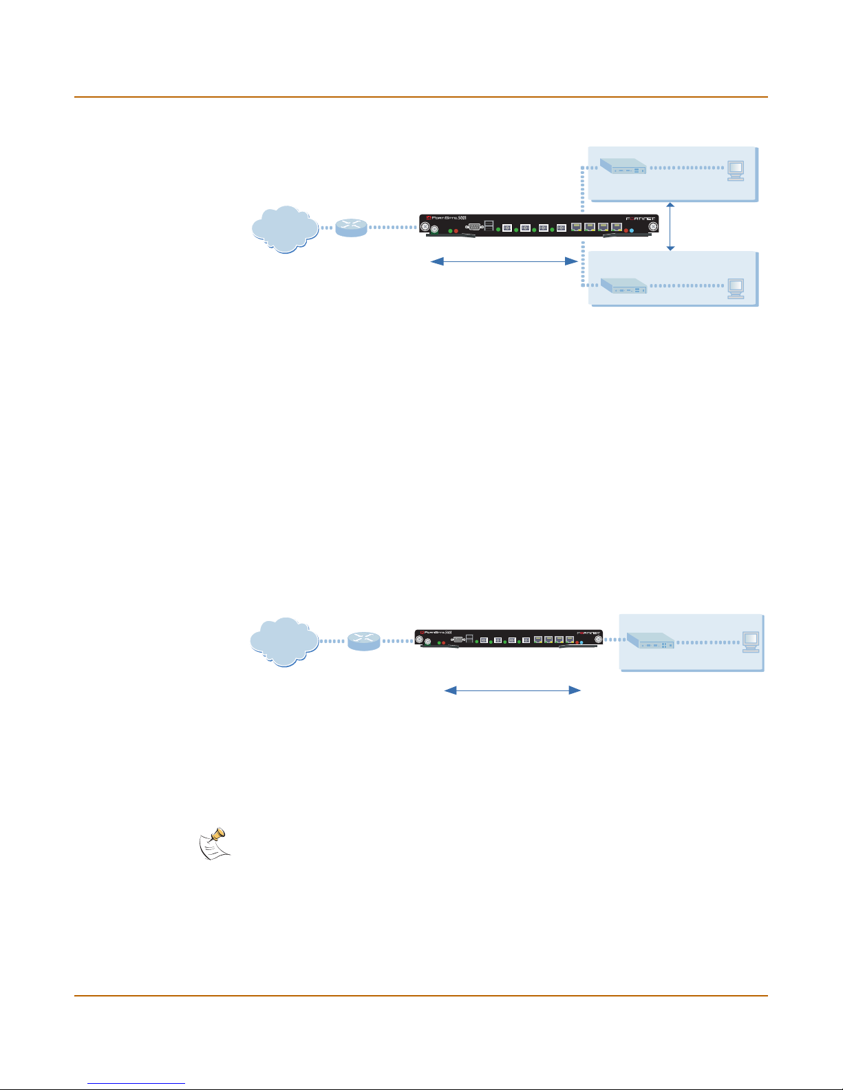
Figure 1: Example NAT/Route mode standalone network configuration
Internal network
Port 1
192.168.1.99
STA IPM
Internet
Port 2
204.23.1.5
FortiGate-5001SX Module
in NAT/Route mode
USB
1 2 3 4 5 6 7 8
CONSOLE
PWRACC
192.168.1.3
Route mode policies
controlling traffic between
internal networks.
NAT mode policies controlling
traffic between internal and
external networks.
Port 3
10.10.10.1
DMZ network
10.10.10.2
Transparent mode standalone configuration
In Transparent mode standalone configuration, each FortiGate-5000 antivirus firewall
module in the FortiGate chassis operates as a separate Transparent mode FortiGate
antivirus firewall. Each of these FortiGate-5000 modules is invisible to the network.
Similar to a network bridge, the FortiGate interfaces must be on the same subnet. You
only have to configure a management IP address so that you can make configuration
changes. The management IP address is also used for antivirus and attack definition
updates.
Y o u typically use a FortiGate-5 000 antivirus firewall module in Transparent mode on a
private network behind an existing firewall or behind a router. The FortiGate-5000
module performs most of the same firewall functions in Transparent mode as in
NAT/Route mode.
Figure 2: Example Transparent mode standalone network configuration
FortiGate-5001SX Module
in Transparent mode
USB
1 2 3 4 5 6 7 8
CONSOLE
PWRACC
192.168.1.2
Management IP
STA IPM
Port 2
Internal network
192.168.1.3
Internet
Gateway to
public network
204.23.1.5
(firewall, router)
192.168.1.1
Port 1
HA configuration
You can group two or more FortiGate-5000 modules in a FortiGate chassis into an HA
cluster. The HA cluster can operate in active-active mode or active-passive mode.
Note: When clustering FortiGate units, you must cluster the same modules together, for
example, two or more FortiGate-5002FB2 modules. You cannot cluster one FortiGate-5001SX
module and one FortiGate-5002FB2 module together.
An active-active HA cluster can increase virus scanning throughput by using load
balancing to distribute virus scanning to all of the FortiGate units in the cluster.
Both HA modes provide supports link redundancy and device r edundancy.
12 01-28011-0259-20060210 Fortinet Inc.
Transparent mode policies
controlling traffic between
internal and external networks
Page 13
Configuring the FortiGate for the Ne tw o r k
Link
redundancy
Device
redundancy
If one of the links to a FortiGate unit in an HA cluster fails, all functions, all
established firewall connections, and all IPSec VPN sessionsa are maintained
by the other FortiGate units in the HA cluster.
If one of the FortiGate units in an HA cluster fails, all functions, all established
firewall connections, and all IPSec VPN sessions are maintained by the other
FortiGate units in the HA cluster.
a.HA does not provide session failover for PPPoE, DHCP, PPTP, and L2TP services.
Once the FortiGate-5000 modules are added to the HA cluster, the cluster functions
on your network as a single module with n interfaces where n is the number of
FortiGate-5000 modules multiplied by the available interfaces on the module. The
cluster manages communication and load balancing between the modules.
You can operate an HA cluster in NAT/Route or Transparent mode. For more
information on HA, see “High availability installation” on page 32.
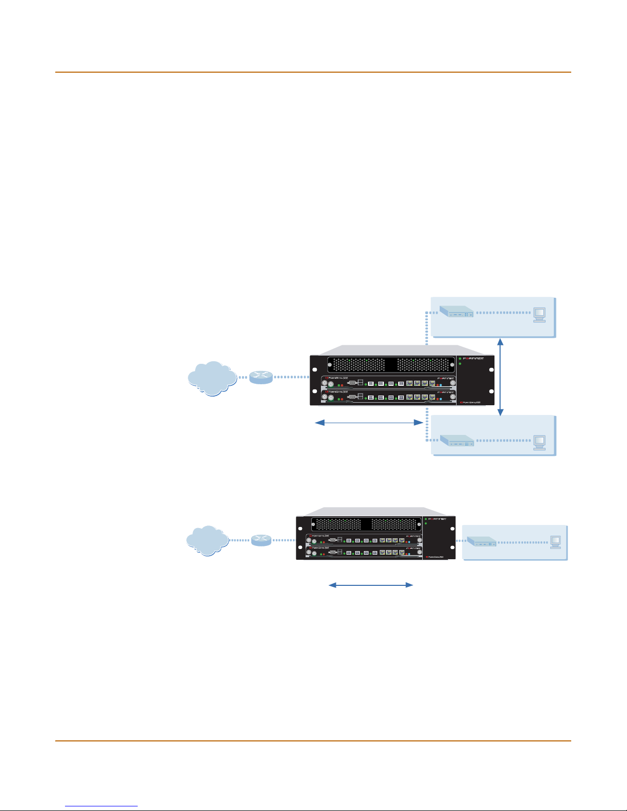
Figure 3: HA network configuration in NAT/Route mode
Internal network
192.168.1.3
Route mode policies
controlling traffic between
internal networks.
Internet
FortiGate-5001SX HA cluster in in NAT/Route
mode in a FortiGate-5020 chassis
Port2
204.23.1.5
USB
1 2 3 4 5 6 7 8
CONSOLE
ACC
PWR
USB
1 2 3 4 5 6 7 8
CONSOLE
PWRACC
Port1
192.168.1.99
PSUA
PSU B
STA IPM
STA IPM
NAT mode policies controlling
traffic between internal and
external networks.
Figure 4: HA network configuration in Transparent mode
FortiGate-5001SX HA Cluster in Transparent
mode in a FortiGate-5020 chassis
PSUA
PSU B
STA IPM
STA IPM
Internet
Gateway to
public network
204.23.1.5
(firewall, router)
192.168.1.1
Port1
USB
1 2 3 4 5 6 7 8
CONSOLE
PWRACC
USB
1 2 3 4 5 6 7 8
CONSOLE
PWRACC
192.168.1.2
Management IP
Transparent mode policies
controlling traffic between
internal and external networks
Port 3
10.10.10.1
DMZ network
Port2
10.10.10.2
Internal network
192.168.1.3
FortiGate-5000 series Installation Guide 01-28011-0259-20060210 13
Page 14

Configuration options Configuring the FortiGate for the Network
Configuration options
Once you have selected Transparent or NAT/Route mode operation, you can
complete the configuration plan and begin to configure the FortiGate unit. Choose
among three different tools to configure the FortiGate modules.
Web-based manager and setup wizard
The FortiGate web-based manager is a full featured management tool. You can use
the web-based manager to configure most FortiGate settings.
The web-based manager Setup Wizard guides you through the initial configuration
steps. Use the Setup Wizard to configure the administrator password, the interface
addresses, the default gateway address, and the DNS server addresses. Optionally,
use the Setup Wizard to configure the internal server settings for NAT/Route mode.
To connect to the web-based manager you require:
• Ethernet conne ction be twe en th e FortiGa te mod ule and a mana gem ent computer.
• Internet Explorer version 6.0 or higher on the management computer.
CLI
The FortiGate CLI is a full-featured management tool. Use it to configure the
administrator password, the interface addresses, the default gateway address, and
the DNS server addresses. To connect to the CLI you require:
• Serial connection between the FortiGate module and a management computer.
• A terminal emulation application on the management computer.
If you are configuring the FortiGate antivirus firewall module to oper ate in T ransp arent
mode, you can switch to Transparent mode from the web-based manager and then
use the setup wizard to add the administr ation password, the manag ement IP address
and gateway, and the DNS server addresses.
Connecting to the web-based manager
Use the following procedure to connect to the web-based manager for the first time.
Configuration changes made with the web-based manager are effective immediately
without resetting the firewall or interrupting service.
To connect to the web-based manager, you need:
• a computer with an ethernet connection
• Internet Explorer version 6.0 or higher
• an optical fiber patch or copper ethernet cable required to connect port 1 of the
FortiGate-5000 module to your network
Note: You can use the web-based manager with recent versions of most popular web
browsers. The web-based manager is fully supported for Internet Explorer version 6.0 or higher.
14 01-28011-0259-20060210 Fortinet Inc.
Page 15

Configuring the FortiGate for the Network Connecting to the web-based manager
By default, you can connect to the web-based manager using the FortiGate-5000
module port 1. If you cannot connect port 1 to your network, you can use the FortiGate
CLI to add an IP address to one of the other FortiGate module ports.
Note: You may not be able to connect port 1 to your network if port 1 is an optical interface and
you do not have access to an optical network) you can change.
Connecting to the web-based manager using port 1
1 Set the IP address of the computer with an ethernet connection to the static IP
address 192.168.1.2 and a netmask of 255.255.255.0.
2 Connect the port 1 of the FortiGate unit to your optical network.
3 Connect the interface of the computer to the sam e net wor k.
4 Start Internet Explorer and browse to the address https://192.168.1.99 (remember to
include the “s” in https://).
The FortiGate login is displayed.
5 Type admin in the Name field and select Login.
To connect to the web-based manager using interface 5
1 Connect to the FortiGate-5000 module command line interface (C LI) see, “Connecting
to the command line interface (CLI)” on page 16.
2 Set the IP address and netmask of port 1 to an IP address accessible by the computer
with an ethernet connection and configure port 1 to allow HTTPS management
connections.
config system interface
edit port1
set ip <IP_address> <netmask>
set allowaccess https
end
Example
To set the IP address of port 1 to 192.168.20.99 and netmask to 255.255.255.0, enter:
config system interface
edit port1
set ip 192.168.20.99 255.255.255.0
set allowaccess https
end
Note: The default IP address of the port 1 is 192.168.1.99 and the default IP address of the
interface 2 is 192.168.100.99. You cannot set the IP address of interface 5 to be on the same
subnets as port 1 and 2.
3 Set the IP address of the computer with an ethernet connection to a static IP address
on the same subnet as interface 5.
4 Connect port 1 to the same network as the management computer.
5 Star t Internet Explorer and browse to the address https://<IP_address> (remember to
include the “s” in https://).
The FortiGate login is displayed.
FortiGate-5000 series Installation Guide 01-28011-0259-20060210 15
Page 16

Connecting to the command line interface (CLI) Configuring th e FortiGate for the Network
!
Figure 5: FortiGate login
6 Type admin in the Name field and select Login.
Connecting to the command line interface (CLI)
As an alternative to the web-based manager, you can install and configure the
FortiGate unit using the CLI. Configuration changes made with the CLI are effective
immediately without resetting the firewall or interrupting service.
To connect to the FortiGate CLI, you need:
• a computer with an available communication s port
• the serial cable included in your FortiGate package
• terminal emulation software such as HyperTerminal for Windows
Note: The following procedure describes how to connect to the CLI using Windows
HyperTerminal software. You can use any terminal emulation program.
To connect to the CLI
1 Connect the serial cable to the communications port of your computer and to the
FortiGate Console port.
Caution: Make sure that you do not accidentally open the extraction lever when connecting the
serial cable to the FortiGate-5000 module. If this extraction lever is opened the module could
power down or reboot.
2 Make sure that the FortiGate chassis is powered on.
3 Start HyperTerminal, enter a name for the connection, and select OK.
4 Configure HyperTerminal to connect directly to the communications port on your
computer and select OK.
5 Select the following port settings and select OK.
16 01-28011-0259-20060210 Fortinet Inc.
Page 17

Configuring the FortiGate for the Network NAT/Route mode installation
Bits per second 9600
Data bits 8
Parity None
Stop b its 1
Flow control None
6 Press Enter to connect to the FortiGate CLI.
A prompt similar to the following is displayed:
FortiGate-5001 login:
7 Type admin and press Enter twice.
The following prompt is displayed:
Welcome !
Type ? to list available commands. For information about how to use the CLI, see the
FortiGate CLI Reference Guide.
NAT/Route mode installation
This section describes how to install the FortiGate-5000 module in NAT/Route mode.
For information about installing a FortiGate-5000 module in Transparent mode, see
“NAT/Route mode installation” on page 17. For information about installing two or
more FortiGate-5000 module in HA mode, see “High availability installation” on
page 32. For more information about installing the FortiGate-5000 module in
NAT/Route mode, see “Configuring the FortiGate for the Network” on page 11.
This section describes:
• Preparing to configure the FortiGate module in NAT/Route mode
• Using the web-based manager
• Using the command line interface
• Using the setup wizard
• Connecting the FortiGate unit to the network(s)
• Configuring the networks
• Next steps
Preparing to configure the FortiGate module in NAT/Route mode
Use Table 1 to gather the informa tio n th at yo u ne ed t o custo m ize NAT/Route mode
settings.
You can configure the FortiGate-5000 module in seve ral ways:
• the web-based manager GUI is a complete inte rface for co nfigur ing most setting s.
See “Using the web-based manager” on page 19.
• the command l ine interface (CLI) is a comp lete text-based interfa ce for configuring
all settings. See “Using the command line interface” on page 20.
• the setup wizard provides easy, fast configuration of the most basic settings to get
the unit up and running quickly. See “Using the setup wizard” on page 23.
FortiGate-5000 series Installation Guide 01-28011-0259-20060210 17
Page 18

NAT/Route mode installation Configuring the FortiGate for the Network
The method that you choose depends on the complexity of the configuration, access
and equipment, and the type of interface you are most comfortable using.
Table 1: NAT/Route mode settings
Administrator Password:
Port 1
Port 2
Port 3
Port 4
Port 5
Port 5
Port 6
Port 7
(FortiGate-5001SX
and
FortiGate-5001FA2
only)
Port 8
(FortiGate-5001SX
and
FortiGate-5001FA2
only)
IP: _____._____._____._____
Netmask: _____._____._____._____
IP: _____._____._____._____
Netmask: _____._____._____._____
IP: _____._____._____._____
Netmask: _____._____._____._____
IP: _____._____._____._____
Netmask: _____._____._____._____
IP: _____._____._____._____
Netmask: _____._____._____._____
IP: _____._____._____._____
Netmask: _____._____._____._____
IP: _____._____._____._____
Netmask: _____._____._____._____
IP: _____._____._____._____
Netmask: _____._____._____._____
IP: _____._____._____._____
Netmask: _____._____._____._____
Default Gateway: _____._____._____._____
Interface connected to
external network (usually
port2):
Network settings
18 01-28011-0259-20060210 Fortinet Inc.
A default route consists of a default gateway and the name of the
interface connected to the external network (usually the Internet).
The default gateway directs all non-local traffic to this interface and
to the external network.
Primary DNS Server: _____._____._____._____
Secondary DNS Server: _____._____._____._____
Page 19

Configuring the FortiGate for the Network NAT/Route mode installation
DHCP or PPPoE configuration
You can configure any FortiGate interface to acquire its IP address from a DHCP or
PPPoE server. Your ISP may provide IP addresses using one of these protocols.
To use the FortiGate DHCP server, you need to configure an IP address range and
default route for the server . No configuration information is required for inter faces that
are configured to use DHCP.
PPPoE requires you to supply a user name and password. In addition, PPPoE
unnumbered configurations require you to supply an IP address. Use Table 2 to
record the information you require for your PPPoE configuration.
Table 2: PPPoE settings
User name:
Password:
Using the web-based manager
Y ou ca n use the web-base d manager for the in itial configuration of the FortiGate-5000
module. You can also continue to use the web-based manager for all FortiGate unit
settings.
For information about connecting to the web-based manager, see “Connecting to the
web-based manager” on page 14.
Configuring basic settings
After connecting to the web-based manager you can use the following procedures to
complete the basic configuration of the FortiGate-5000 module.
To add/change the administrator password
1 Go to System > Admin > Administrators.
2 Select the Change Password icon for the admin administrator.
3 Enter the new password and enter it again to confirm.
4 Select OK.
To configure interfaces
1 Go to System > Network > Interface.
2 Select the edit icon for an interface.
FortiGate-5000 series Installation Guide 01-28011-0259-20060210 19
Page 20

NAT/Route mode installation Configuring the FortiGate for the Network
3 Set the addressing mode for the interface.
Choose from manual, DHCP, or PPPoE.
4 Complete the addressing configuration.
• For manual addressing, enter the IP address and netmask for the interface.
• For DHCP addressing, select DHCP and any required settings.
• For PPPoE addressing, select PPPoE, and enter the username and password and
any other required settings.
For information about how to configure these and other interface settings, see the
FortiGate online help or the FortiGate Administration Guide.
5 Select OK.
6 Repeat this procedure for each interface.
Note: If you change the IP address of the interface you are connecting to, you must connect
through a web browser again using the new address. Browse to https:// followed by the new IP
address of the interface. If the new IP address of the interface is on a different subnet, you may
have to change the IP address of your computer to the same subnet.
To configure DNS server settings
1 Go to System > Network > DNS.
2 Enter the IP address of the primary DNS server.
3 Enter the IP address of the secondary DNS server.
4 Select OK.
To add a default route
Add a default route to configure where the FortiGate-5000 module sends traffic
destined for an external network (usually the Internet). Adding the default route also
defines which interface is connected to an external network. The default route is not
required if the interface connected to the external network is configured using DHCP
or PPPoE.
1 Go to System > Router > Static.
2 If the Static Route table contains a default route (IP and Mask set to 0.0.0.0), select
the Delete icon to delete this route.
3 Select Create New.
4 Set Destination IP to 0.0.0.0.
5 Set Mask to 0.0.0.0.
6 Set Gateway to the default gateway IP address.
7 Set Device to the interface connected to the external network.
8 Select OK.
Using the command line interface
You can also configure the FortiGate-5000 modu le using the command line interface
(CLI). For information about connecting to the CLI, see “Connecting to the command
line interface (CLI)” on page 16.
20 01-28011-0259-20060210 Fortinet Inc.
Page 21

Configuring the FortiGate for the Network NAT/Route mode installation
Configuring the FortiGate module to operate in NAT/Route mode
Use the information that you gathered in Table 1 on page 18 to complete the following
procedures.
To add/change the administrator password
1 Log in to the CLI.
2 Change the admin administrator password. Enter:
config system admin
edit admin
set password <psswrd>
end
To configure interfaces
1 Log in to the CLI.
2 To set the IP address and netmask of port1, enter:
config system interface
edit port1
set ip <address_ip> <netmask>
end
Example
To set the IP address of port1 to 192.168.20.99 and netmask to 255.255.255.0, enter:
config system interface
edit port1
set ip 192.168.20.99 255.255.255.0
end
3 To set the IP address and netmask of port2, enter:
config system interface
edit port2
set ip <address_ip> <netmask>
end
Example
To set the IP address of port 1 to 204.23.1.5 and netmask to 255.255.255.0, enter:
config system interface
edit port1
set ip 204.23.1.5 255.255.255.0
end
To set port2 to use DHCP, enter:
config system interface
edit port2
set mode dhcp
FortiGate-5000 series Installation Guide 01-28011-0259-20060210 21
Page 22

NAT/Route mode installation Configuring the FortiGate for the Network
end
To set the port2 to use PPPoE, enter:
config system interface
edit port2
set mode pppoe
set username user@domain.com
set password mypass
set connection enable
end
4 Use the same syntax to set the IP address of each FortiGate interface as required.
5 Confirm that the addresses are correct. Enter:
get system interface
The CLI lists the IP address, netmask, and other settings for each of the FortiGate
interfaces.
To configure DNS server settings
• Set the primary and secondary DNS server IP addresses. Enter
config system dns
set primary <address_ip>
set secondary <address_ip>
end
Example
config system dns
set primary 293.44.75.21
set secondary 293.44.75.22
end
To add a default route
Add a default route to configure where the FortiGate-5000 module sends traffic that
should be sent to an external network (usually the Internet). Adding the default route
also defines which interface is connected to an external network. The default route is
not required if the interface connected to the external network is configured using
DHCP or PPPoE.
22 01-28011-0259-20060210 Fortinet Inc.
Page 23

Configuring the FortiGate for the Network NAT/Route mode installation
• Set the default route to the Defa ult Gateway IP address. Enter:
config router static
edit 1
set dst 0.0.0.0 0.0.0.0
set gateway <gateway_IP>
set device <interface>
end
Example
If the default gateway IP is 204.23.1.2 and this gatew ay is conn ec te d to po rt 2:
config router static
edit 1
set dst 0.0.0.0 0.0.0.0
set gateway 204.23.1.2
set device port2
end
Using the setup wizard
From the web-based manager, you can use the setup wizard to complete the initial
configuration of the FortiGate-5000 module. For information about connecting to the
web-based manager, see “Connecting to the web-based manager” on page 14.
If you are configuring the FortiGate-5000 module to operate in NAT/Route mode (the
default), you can use the setup wizard to:
• add the administration password
• configure the internal interface address
• choose either a manual (static) or a dynamic (DHCP or PPPoE) address for the
external interface
• add a default route for the external interface
• add the DNS server IP addresses
• add the DHCP server settings and IP addresses
• add various internal server IP addresses including web, IMAP, POP3, SMTP, and
FTP servers
• set the antivirus protection to high, medium, or none
Table 3 lists the additional settings that you can configure with the setup wizard. See
Table 1 on page 18 and Table 2 on page 19 for other settings .
Table 3: Setup wizard settings
Password Prepare an administrator password.
Internal Interface
External Interface
Use the information you gathered in Table 1 on page 18.
The Internal interface in the setup wizard refers to Port 1 of the
FortiGate-5000 module.
Use the information you gathered in Table 1 on page 18.
The External interface in the setup wizard refers to Port2 of the
FortiGate-5000 module.
FortiGate-5000 series Installation Guide 01-28011-0259-20060210 23
Page 24

NAT/Route mode installation Configuring the FortiGate for the Network
Table 3: Setup wizard settings
Starting IP: _____._____._____._____
Ending IP: _____._____._____._____
Netmask: _____._____._____._____
DHCP server
Internal servers
Antivirus
Default
Gateway:
DNS IP: _____._____._____._____
Your FortiGate firewall contains a DHCP server to automatically set up
the addresses of computers on your internal network
Web Server: _____._____._____._____
SMTP Server: _____._____._____._____
POP3 Server: _____._____._____._____
IMAP Server: _____._____._____._____
FTP Server: _____._____._____._____
If you provide access from the Internet to a web server, SMTP server,
POP3 server IMAP server, or FTP server installed on an internal
network, add the IP addresses of the servers here.
High Create a protection profile that enables virus
scanning, file blocking, and blocking of oversize
email for HTTP, FTP, IMAP, POP3, and SMTP. Add
this protection profile to a default firewall policy.
Medium Create a protection profile that enables virus
scanning, for HTTP, FTP, IMAP, POP3, and SMTP
(recommended). Add this protection profile to a
default firewall policy.
None Do not configure antivirus protection.
Select one of these security levels to protect your network from viruses.
_____._____._____._____
Starting the setup wizard
1 In the web-based manager, select Easy Setup Wizard.
Figure 6: Select the Easy Setup Wizard
2 Follow the instructions on the wizard pages and use the information that you gathered
in Table 1 on page 18 and Table 3 on page 23 to fill in the wizard fields.
3 Select the Next button to step through the wizard pages.
24 01-28011-0259-20060210 Fortinet Inc.
Page 25

Configuring the FortiGate for the Network NAT/Route mode installation
4 Confirm the configuration settings, and then select Finish and Close.
Note: If you change the IP address of the interface you are connecting to, you must connect
through a web browser again using the new address. Browse to https:// followed by the new IP
address of the interface. If the new IP address of the interface is on a different subnet, you may
have to change the IP address of your computer to the same subnet.
Note: If you use the setup wizard to configure internal server settings, the FortiGate-5000
module adds port forwarding virtual IPs and firewall policies for each server. For each server
located on the network connected to Port 1 the FortiGate-5000 module adds a Port2->Port1
firewall policy.
You are now finished the initial configuration of the FortiGate-5000 module.
Connecting the FortiGate unit to the network(s)
After you complete the initial configuration, you can con ne ct the F or tiG ate - 50 00
module between the internal network and the Internet.
For the FortiGate-5001SX module and the FortiGate-5001FA2, connect interfaces 1
to 4 to gigabit fiber-optic ethernet networks or copper networks depend ing on the SPF
connectors that you have purchased. Connect interfaces 5 to 8 to gigabit copper
ethernet networks.
For the FortiGate-5002FB2 module, connect interfaces 1-6 to gigabit copper ethernet
networks.
Figure 7: FortiGate-5001SX example NAT/Route mode connections
Internal Network
Hub or Switch
Port 6
Port 1
USB
CONSOLE
PWR ACC
Public Switch
or Router
1 2 3 4 5 6 7 8
Port 2
FortiGate-5001SX
STA IPM
Internet
Network
Web Server
Mail Server
FortiGate-5000 series Installation Guide 01-28011-0259-20060210 25
Page 26

Transparent mode installation Configuring the FortiGate for the Network
Configuring the networks
If you are running a FortiGate-5000 mod u le in NAT/Route mode, you need to
configure the networks to route all Internet traffic to the IP address of the FortiGate
interface to which they are connected.
If you are using the FortiGate-5000 module as the DHCP server for your internal
network, configure the computers on your internal network for DHCP.
Make sure that the connected FortiGate-5000 module is functioning properly by
connecting to the Internet from a computer on the internal network. You should be
able to connect to any Internet address.
Transparent mode installation
This section describes how to install a For tiGate-5000 module in T ransp arent mode. If
you want to install the FortiGate-5000 module in NAT/Route mode, see “NAT/Route
mode installation” on page 17. If you want to install two or more FortiGate-5000
modules in HA mode, see “High availability installation” on page 32. For more
information about installing the FortiGate-5000 module in Transparent mode, see
“Configuring the FortiGate for the Network” on page 11.
This section describes:
• Preparing to configure the FortiGate module in NAT/Route mode
• Using the web-based manager
• Using the command line interface
• Using the setup wizard
• Connecting the FortiGate unit to the network(s)
Preparing to configure Transparent mode
Use Table 4 to gather the informa tio n th at yo u ne ed to cu sto m ize Transparent mode
settings.
You can configure T ransparent mode using four methods:
• the web-based manager GUI
• command line interface (CLI)
• setup wizard
The method you choose depends on the complexity of the configuration, access and
equipment, and the type of interface you are most comfortable using.
26 01-28011-0259-20060210 Fortinet Inc.
Page 27

Configuring the FortiGate for the Ne tw o r k Transparent mode installation
Table 4: Transparent mode settings
Administrator Password:
IP: _____._____._____._____
Netmask: _____._____._____._____
Management IP
The management IP address and netmask must be valid for the network
from which you will manage the FortiGate unit. Add a default gateway if the
FortiGate unit must connect to a router to reach the management
computer.
DNS Settings
Default Gateway: _____._____._____._____
Primary DNS Server: _____._____._____._____
Secondary DNS Server: _____._____._____._____
Using the web-based manager
You can use the web-based manager to complete the initial configuration of the
FortiGate-5000 module. You can continue to use the web-based manager for all
FortiGate-5000 module settings.
For information about connecting to the web-based manager, see “Connecting to the
web-based manager” on page 14.
The first time you connect to the FortiGate-5000 module, it is configured to run in
NAT/Route mode.
To switch to Transparent mode using the web-based manager
1 Go to System > Status.
2 Select Change beside the Operation Mode.
3 Select Transparent in the Operation Mode list.
4 Select OK.
To reconnect to the web-based manager, change the IP address of the management
computer to 10.10.10.2. Connect to the internal interface and browse to https://
followed by the Transparent mode management IP address. The default FortiGate
Transparent mode management IP address is 10.10.10.1.
To change the Management IP
1 Go to System > Network > Management.
2 Enter the management IP address and netmask that you recorded in Table 4 on
page 27.
3 Select access methods and logging for any interfaces as required.
4 Select Apply.
FortiGate-5000 series Installation Guide 01-28011-0259-20060210 27
Page 28

Transparent mode installation Configuring the FortiGate for the Network
To configure DNS server settings
1 Go to System > Network > DNS.
2 Enter the IP address of the primary DNS server.
3 Enter the IP address of the secondary DNS server.
4 Select OK.
To configure the default gateway
1 Go to System > Network > Management.
2 Set Default Gateway to the default gateway IP address that you recorded in Table 4
on page 27.
3 Select Apply.
Reconnecting to the web-based manager
If you changed the IP address of the management interface while you were using the
setup wizard, you must reconnect to the web-based manager using the new IP
address. Browse to https:// followed by the new IP address of the management
interface. Otherwise, you can reconnect to the web-based manager by browsing to
https://10.10.10.1. If you connect to the management interface th rough a router, make
sure that you have added a default gateway for that router to the management IP
default gateway field.
Using the command line interface
As an alternative to the web-based manager or setup wizard you can begin the initial
configuration of the FortiGate-5000 module using the command line interface (CLI).
To connect to the CLI, see “Connecting to the command line interface (CLI)” on
page 16. Use the information that you gathered in Table 4 on page 27 to complete the
following procedures.
To change to T ransparent mode using the CLI
1 Make sure that you are logged into the CLI.
2 Switch to Transpar ent mode. Enter:
config system global
set opmode transparent
end
The FortiGate unit restarts. After a few seconds, the login prompt appears.
3 Type admin and press Enter.
The following prompt appears:
Welcome !
4 Confirm that the FortiGate unit has switched to Transparent mode. Enter:
get system status
The CLI displays the status of the FortiGate unit including the following line of text:
Operation mode: Transparent
28 01-28011-0259-20060210 Fortinet Inc.
Page 29

Configuring the FortiGate for the Ne tw o r k Transparent mode installation
To configure the management IP address
1 Make sure that you are logged into the CLI.
2 Set the management IP address and netmask to the IP address and netma sk that you
recorded in Table 4 on page 27. Enter:
config system manageip
set ip <address_ip> <netmask>
end
Example
config system manageip
set ip 10.10.10.2 255.255.255.0
end
3 Confirm that the address is correct. Enter:
get system manageip
The CLI lists the management IP address and netmask.
To configure DNS server settings
1 Set the primary and secondary DNS server IP addresses. Enter
config system dns
set primary <address_ip>
set secondary <address_ip>
end
Example
config system dns
set primary 293.44.75.21
set secondary 293.44.75.22
end
To configure the default gateway
1 Make sure that you are logged into the CLI.
2 Set the default route to the default gateway that you recorded in Table 4 on page 27.
Enter:
config router static
edit 1
set dst 0.0.0.0 0.0.0.0
set gateway <address_gateway>
set device <interface>
end
FortiGate-5000 series Installation Guide 01-28011-0259-20060210 29
Page 30

Transparent mode installation Configuring the FortiGate for the Network
Example
If the default gateway IP is 204.23.1.2 and this gatew ay is conn ec te d to po rt 2:
config router static
edit 1
set dst 0.0.0.0 0.0.0.0
set gateway 204.23.1.2
set device port2
end
Using the setup wizard
From the web-based manager, you can use the setup wizard to begin the initial
configuration of the FortiGate-5000 module. For information about connecting to the
web-based manager, see “Connecting to the web-based manager” on page 14.
The first time you connect to the FortiGate-5000 module, it is configured to run in
NAT/Route mode.
To switch to Transparent mode using the web-based manager
1 Go to System > Status.
2 Select Change beside the Operation Mode.
3 Select Transparent in the Operation Mode list.
4 Select OK.
To reconnect to the web-based manager, change the IP address of the management
computer to 10.10.10.2. Connect to the internal interface and browse to https://
followed by the Transparent mode management IP address. The default FortiGate
Transparent mode management IP address is 10.10.10.1.
To start the setup wizard
1 Select Easy Setup Wizard (the middle button in the upper-right corner of the
web-based manager).
2 Use the information that you gathered in Table 4 on page 27 to fill in the wizard fields.
Select the Next button to step through the wizard pages.
3 Confirm your configuration settings, and then select Finish and Close.
Reconnecting to the web-based manager
If you changed the IP address of the management interface while you were using the
setup wizard, you must reconnect to the web-based manager using the new IP
address. Browse to https:// followed by the new IP address of the management
interface. Otherwise, you can reconnect to the web-based manager by browsing to
https://10.10.10.1. If you connect to the management interface th rough a router, make
sure that you have added a default gateway for that router to the management IP
default gateway field.
30 01-28011-0259-20060210 Fortinet Inc.
Page 31

Configuring the FortiGate for the Ne tw o r k Transparent mode installation
Connecting the FortiGate module to your network
After you complete the initial configuration, you can con ne ct the F or tiG ate - 50 00
module to your network.
For the FortiGate-5001SX and the FortiGate-5001FA2 module, connect interfaces 1
to 4 to gigabit fiber-optic ethernet networks or copper gigabit networks depending on
the SPF interfaces that yo have purchased. Connect interfaces 5 to 8 to gigabit
copper ethernet networks.
For the FortiGate-5002FB2 module, connect interfaces 1-6 to gigabit copper ethernet
networks.
Figure 8: FortiGate-5001SX example Transparent mode connections
Internal Network
Hub or Switch
Port 1
USB
CONSOLE
PWR ACC
FortiGate-5001SX
Port 5
1 2 3 4 5 6 7 8
Port 2
Public Switch
or Router
Internet
Other Network
STA IPM
Port 6
FortiGate-5000 series Installation Guide 01-28011-0259-20060210 31
Other Network
Page 32

High availability installation Configuring the FortiGate for the Network
High availability installation
This section describes how to install two or more FortiGate-5000 module in an HA
cluster within a FortiGate chassis. HA installation involves three basic steps:
• Configuring FortiGate-5000 modules for HA operation
• Connecting the cluster to your networks
• Installing and configuring the cluster
For information about HA, see the FortiGate Administration Guide and the FortiOS
High Availability technical note.
Priorities of heartbeat device and monitor priorities
The procedures in this section do not include steps for changing the priorities of
heartbeat devices or for configuring monitor priorities settings. Both of these HA
settings should be configured after the cluster is up and running.
By default, port 9 and port 10 are configured as heartbeat devices. Port 9 and port 10
are only used for HA cluster communication and are not physically accessible. These
interfaces are not visible on the web-based manager, but they are visible on the CLI.
Configuring FortiGate-5000 modules for HA operation
A FortiGate HA cluster consists of two or more FortiGate-5000 module with the same
HA configuration.
Note: When clustering antivirus firewalls, you must cluster similar modules together, for
example, two or more FortiGate-5002FB2 modules. You cannot cluster one FortiGate-5001SX
and one FortiGate-5002FB2 module together.
This section describes how to configure and add each of the FortiGate-5000 modules
to a cluster for HA operation. The procedures are the same for active-active and
active-passive HA.
• High availability configuration settings
• Configuring FortiGate-5000 modules for HA using the web-based manager
• Configuring FortiGate-5000 modules for HA using the CLI
High availability configuration settings
Use the following table to select the HA configuration settings for the FortiGate-5000
modules in the HA cluster.
32 01-28011-0259-20060210 Fortinet Inc.
Page 33

Configuring the FortiGate for the Network High availability installation
Table 5: High availability settings
Mode
Group ID
Unit priority
Override
Master
Active-Active Load balancing and failover HA. Each FortiGate-5000
module in the HA cluster actively processes connections
and monitors the status of the other FortiGate-5000
modules in the cluster. The primary FortiGate-5000 module
in the cluster controls load balancing.
Active-Passive Failover HA. The primary FortiGate-5000 module in the
cluster processes all connections. All other FortiGate-5000
modules in the cluster are passively monitor the cluster
status and remain synchronized with the primary FortiGate-
5000 module.
You must set all members of the HA cluster to the same HA mode.
The group ID range is from 0 to 63. All members of the HA cluster must have
the same group ID.
When the FortiGate-5000 modules in the cluster are switched to HA mode,
all of the interfaces of all of the units in the cluster get the same virtual MAC
address. This virtual MAC address is set according to the group ID.
Group ID MAC Address
0 00-09-0f-06-ff-00
1 00-09-0f-06-ff-01
2 00-09-0f-06-ff-02
3 00-09-0f-06-ff-03
…
63 00-09-0f-06-ff-3f
If you have more than one HA cluster on the same network, each cluster
should have a different group ID. If two clusters on the same network have
same group ID, the duplicate MAC addresses cause addressing conflicts on
the network.
The FortiGate-5000 module with the highest priority becomes the primary
module in the cluster. The unit priority range is 0 to 255. The default unit
priority is 128.
Set the module priority to a higher value if you want a FortiGate-5000
module to be the primary cluster module. Set the module priority to a lower
value if you want a FortiGate-5000 module to be a subordinate module in the
cluster. If all modules have the same priority, the FortiGate-5000 module
with the highest serial number becomes the primary cluster module.
You can configure a FortiGate-5001SX module to always become the
primary module in the cluster by giving it a high priority and by selecting
Override master.
FortiGate-5000 series Installation Guide 01-28011-0259-20060210 33
Page 34

High availability installation Configuring the FortiGate for the Network
Table 5: High availability settings (Continued)
The schedule controls load balancing among the FortiGate-5000 modules in
the active-active HA cluster. The schedule must be the same for all
FortiGate-5000 modules in the HA cluster.
Schedule
None No load balancing. Select None when the cluster interfaces
Hub Load balancing for hubs. Select Hub if the cluster interfaces
Least
Connection
Round Robin Round robin load balancing. If the FortiGate-5000 modules
Weighted
Round Robin
Random Random load balancing. If the FortiGate-5000 modules are
IP Load balancing according to IP address. If the
IP Port Load balancing according to IP address and port. If the
are connected to load balancing switches.
are connected to a hub. Traffic is distributed to units in a
cluster based on the Source IP and Destination IP of the
packet.
Least connection load balancing. If the FortiGate-5000
modules are connected using switches, select Least
connection to distribute traffic to the cluster module with the
fewest concurrent connections.
are connected using switches, select round robin to
distribute traffic to the next available cluster module.
Weighted round robin load balancing. Similar to round
robin, but weighted values are assigned to each of the
modules in a cluster based on their capacity and on how
many connections they are currently processing. For
example, the primary module should have a lower weighted
value because it handles scheduling and forwards traffic.
Weighted round robin distributes traffic more evenly
because modules that are not processing traffic will be
more likely to receive new connections than modules that
are very busy.
connected using switches, select random to randomly
distribute traffic to cluster modules.
FortiGate-5000 modules are connected using switches,
select IP to distribute traffic to modules in a cluster based
on the Source IP and Destination IP of the packet.
FortiGate-5000 modules are connected using switches,
select IP Port to distribute traffic to units in a cluster based
on the Source IP, Source Port, Destination IP, and
Destination port of the packet.
Configuring FortiGate-5000 modules for HA using the web-based
manager
Use the following procedure to configure each FortiGate-5000 modules for HA
operation.
Note: When configuring FortiGate-5000 modules for HA using the web-based manager, initially
each module will have an identical IP address. Insert the first module fully and configure it first
as the primary module, then add the other FortiGate-5000 modules and configure them as the
subordinates.
To change the FortiGate-5000 module host name
Changing the host name is optional, but you can use host names to identify individual
cluster modules.
1 Connect to the web-based manager.
See “Connecting to the web-based manager” on page 14.
34 01-28011-0259-20060210 Fortinet Inc.
Page 35

Configuring the FortiGate for the Network High availability installation
2 Go to System > Status.
3 In the Host Name field of the Unit Information section, select Change.
4 Type a new host name and select OK.
To configure a FortiGate-5000 module for HA operation
1 Go to System > Config > HA.
2 Select High Availability.
3 Select the mode.
4 Select a Group ID for the HA cluster.
5 If required, change the Unit Priority.
6 If required, select Override master.
7 Enter and confirm a password for the HA cluster.
8 If you are configuring Active-Active HA, se lec t a sche d ule .
9 Select Apply.
The FortiGate-5000 modules negotiates to establish an HA cluster. When you select
apply you may temporarily lose connectivity with the FortiGate module as the
negotiation takes place.
10 Repeat this procedure for all the FortiGate-5000 modules in the cluster. Once all of
the modules are configured, continue with “Connecting the cluster to your networks”
on page 37.
Configuring HA in Transparent mode
Ensure you switch the FortiGate-5000 module to Transparent mode before
configuring the HA cluster.
To configure HA in Transparent mode
1 Go to System > Status.
2 Select Change to Transparent Mode and select OK to switch the FortiGate-5000
module to Transparent mode.
Allow the FortiGate-5000 module to restart in Transparent mode.
3 Set the IP management address.
4 Go to System > Config > HA.
5 Select High Availability.
6 Select the mode.
7 Select a Group ID for the HA cluster.
8 If required, change the Unit Priority.
9 If required, select Override master.
10 Enter and confirm a password for the HA cluster.
11 If you are co nfiguring Active-Active HA, select a schedule.
FortiGate-5000 series Installation Guide 01-28011-0259-20060210 35
Page 36

High availability installation Configuring the FortiGate for the Network
12 Select Apply.
The FortiGate-5000 modules negotiate to establish an HA cluster. When you select
apply you may temporarily lose connectivity with the FortiGate module as the
negotiation takes place.
13 Repeat this procedure for all the FortiGate-5000 modules in the cluster. Once all of
the modules are configured, continue with “Connecting the cluster to your networks”
on page 37.
Configuring FortiGate-5000 modules for HA using the CLI
Use the following procedure to configure each FortiGate-5000 modules for HA
operation.
To change the FortiGate-5000 module host name
1 Connect to the CLI.
See “Connecting to the command line interface (CLI)” on page 16.
2 Change the host name.
config system global
set hostname <name_str>
end
To configure the FortiGate-5000 module for HA operation
1 Configure HA settings.
Use the following command to:
• Set the HA mode
• Set the Group ID
• Change the unit priority
• Enable override master
• Enter an HA password
• Select an active-active HA schedule
config system ha
set mode {a-a | a-p | standalone}
set groupid <id_integer>
set priority <priority_integer>
set override {disable | enable}
set password <password_str>
set schedule {hub | ip | ipport | leastconnection | none
| random | round-robin | weight-round-robin}
end
The FortiGate-5000 module negotiates to establish an HA cluster.
2 Repeat this procedure for all the FortiGate-5000 modules in the cluster. Once all of
the modules are configured, continue with “Connecting the cluster to your networks”
on page 37.
3 If you are configuring a Transparent mode cluster, switch the FortiGate-5000 modules
to Transparent mode.
36 01-28011-0259-20060210 Fortinet Inc.
Page 37

Configuring the FortiGate for the Network High availability installation
config system global
set opmode transparent
end
4 Allow the FortiGate-5000 module to restart in Transparent mode.
5 Repeat this procedure for all of the FortiGate-5000 modules in the cluster then
continue with “Connecting the cluster to your networks” on page 37.
Using the FortiSwitch-5003 in an HA cluster
The FortiSwitch-5003 module is an HA component designed for use in the
FortiGate-5050 and FortiGate-5140 chassis to provide full HA clustering capabilities
between FortiGate-5000 modules. The FortiSwitch-5003 can also provide HA
clustering between multiple FortiGate chassis.
The FortiSwitch-5003 acts as the switch, providing automatic connections through
internal ports 9 and 10 on the backplane of the FortiGate chassis.
Connecting the cluster to your networks
You can connect a cluster operating in NAT/Route mode or Transparent mode. For
clusters within a FortiGate-5050 or FortiGate-5140 chassis, the FortiGate-5000
modules are connected in the cluster to each other thro ugh the FortiSwitch -5003. You
must also connect all matching interfaces in the cluster to the same hub or switch
which connects to your network.
For clusters within a FortiGate-5020, the FortiGate-5000 modules are connected to
each other on the chassis backplane. You must also connect each module to your
network. You must connect all matching interfaces in the cluster to the same hub or
switch. Then you must connect these interfaces to their networks using the same hub
or switch.
Inserting an HA cluster into your network temporarily interrupts communications on
the network because new physical connections are being made to route traf fic through
the cluster. Also, starting the cluster interrupts network traffic until the individual
FortiGate-5000 modules in the cluster are functioning and the cluster completes
negotiation. Cluster negotiation normally takes just a few seconds. During system
startup and negotiation the FortiGate modules drop all network traffic.
Connect the matching interfaces of each FortiGate-5000 module to the same switch
and connect that switch to a network. The following sample shows an HA
configuration with a FortiGate-5020 chassis and two FortiGate-5000 interfaces
connected to two networks.
The modules negotiate to choose the primary cluster unit and the subordinate units.
This negotiation occurs with no user intervention and normally just takes a few
seconds.
FortiGate-5000 series Installation Guide 01-28011-0259-20060210 37
Page 38

High availability installation Configuring the FortiGate for the Network
Figure 9: FortiGate-5020 chassis with two FortiGate-5001SX modules operating in HA
mode
Internal Network
Port 3
1 2 3 4 5 6 7 8
1 2 3 4 5 6 7 8
Port 3
PSUA
PSU B
STA IPM
STA IPM
Hub or
Switch
Hub or
Switch
Port 1
CONSOLE
PWRACC
CONSOLE
PWRACC
Port 1
USB
USB
Router
Internet
The following sample shows an HA configuration with a FortiGate-5050 chassis, three
FortiGate-5001SX modules and two redundant FortiSwitch-5003 modules.
Figure 10: FortiGate-5050 chassis with three FortiGate-5001SX modules operating in HA
mode
Internal Network
Internet
Hub or
Switch
38 01-28011-0259-20060210 Fortinet Inc.
Port 1
Port 1
Port 1
Router
USB
1 2 3 4 5 6 7 8
CONSOLE
PWRACC
5
4
3
2
1
ShMC
2
USB
1 2 3 4 5 6 7 8
CONSOLE
PWRACC
USB
1 2 3 4 5 6 7 8
CONSOLE
PWRACC
ETH
O
RS232ZRE0ZRE1ZRE2
E1
9876543210
1514
1312
SYSTEM
CONSOLE
MANAGEMENT
ETH
O
RS232ZRE0ZRE1ZRE2
SYSTEM
CONSOLE
MANAGEMENT
1110
E2
E1
9876543210
1514
1312
1110
E2
STA IPM
STA IPM
STA IPM
OKCLK
INTEXT
FLT
HOT SWAP
RESET
ZRE
LED MODE
FLT
OKCLK
INTEXT
FLT
HOT SWAP
RESET
ZRE
LED MODE
FLT
CRITICAL
MAJOR
HOT SWAP
ShMC
STATUS
MINOR
ALARM
RESET
ALARMS
1
Port 3
Port 3
Port 3
POWER
ON
Page 39

Configuring the FortiGate for the Network High availability installation
Installing and configuring the cluster
When negotiation is complete the you can configure the cluster as if it was a single
FortiGate-5000 module.
• If you are installing a NAT/Route mode cluster, use the information in “NAT/Route
mode installation” on page 17 to install the cluster on your network
• If you are installing a Transparent mode cluster, use the information in “NAT/Route
mode installation” on page 17 to install the cluster on your network.
The configurations of all of the FortiGate-5000 in the cluster are synchronized so that
the FortiGate-5000 modules can function as a cluster. Because of this
synchronization, you configure and manage the HA cluster instead of managing the
individual FortiGate-5000 modules in the cluster. You can configure and manage the
cluster by connecting to the cluster web-based manager using any cluster interface
configured for HTTPS administrative access. You can also configure and manage the
cluster by connecting to the CLI using any cluster interface configured for SSH
administrative access.
When you connect to the cluster, you are actually connecting to the primary cluster
module. The cluster automatically synchronizes all configuration changes to the
subordinate modules in the cluster as you make the changes.
The only configuration settings that are not synchronized are the HA configuration
(except for the interface heartbeat device and monitoring configuration) and the
FortiGate host name.
For more information about configuring a cluster, see the FortiGate Administration
Guide.
Clustering FortiGate-5000 series chassis
The FortiSwitch-5003 module provides full HA clustering capabilities to provide interchassis communication. The FortiSwitch-5003 acts as the switch, providing automatic
connection through port 9 and 10 the backplane of the chassis.
You can use any of the available 10/100/1000 ports on the FortiSwitch-5003 module
to create an inter-chassis HA cluster.
Using two FortiSwitch-5003 modules in both chassis provides redundant inter-chassis
communication with no single point of failure.
The diagrams shown also apply to the FortiGate-5140 chassis.
Figure 11: FortiGate inter-chassis cluster using a single FortiSwitch-5003 module
USB
1 2 3 4 5 6 7 8
CONSOLE
PWRACC
5
4
3
2
1
ShMC
2
USB
1 2 3 4 5 6 7 8
CONSOLE
PWRACC
USB
1 2 3 4 5 6 7 8
CONSOLE
PWRACC
ETH
O
RS232ZRE0ZRE1ZRE2
E1
1514
1312
SYSTEM
CONSOLE
MANAGEMENT
USB
1 2 3 4 5 6 7 8
CONSOLE
PWRACC
1110
E2
9876543210
STA IPM
STA IPM
STA IPM
OKCLK
INTEXT
FLT
HOT SWAP
RESET
ZRE
LED MODE
FLT
STA IPM
CRITICAL
MAJOR
HOT SWAP
STATUS
MINOR
ALARM
RESET
ALARMS
USB
1 2 3 4 5 6 7 8
CONSOLE
PWRACC
5
4
3
POWER
ON
ShMC
1
2
1
ShMC
2
USB
1 2 3 4 5 6 7 8
CONSOLE
PWRACC
USB
1 2 3 4 5 6 7 8
CONSOLE
PWRACC
ETH
O
RS232ZRE0ZRE1ZRE2
E1
1514
1312
SYSTEM
CONSOLE
MANAGEMENT
USB
CONSOLE
PWRACC
1110
E2
1 2 3 4 5 6 7 8
9876543210
STA IPM
STA IPM
STA IPM
OKCLK
INTEXT
FLT
HOT SWAP
RESET
ZRE
LED MODE
FLT
CRITICAL
MAJOR
MINOR
ALARM
RESET
ALARMS
POWER
STA IPM
ON
HOT SWAP
ShMC
STATUS
1
FortiGate-5000 series Installation Guide 01-28011-0259-20060210 39
Page 40

Next steps Configuring the FortiGate for the Network
Figure 12: FortiGate-5050 inter-chassis cluster using redundant FortiSwitch-5003
modules
USB
1 2 3 4 5 6 7 8
USB
1 2 3 4 5 6 7 8
CONSOLE
PWRACC
5
4
3
2
1
ShMC
2
USB
1 2 3 4 5 6 7 8
CONSOLE
PWRACC
USB
1 2 3 4 5 6 7 8
CONSOLE
PWRACC
ETH
O
RS232ZRE0ZRE1ZRE2
E1
9876543210
1514
1312
SYSTEM
CONSOLE
MANAGEMENT
ETH
O
RS232ZRE0ZRE1ZRE2
SYSTEM
CONSOLE
MANAGEMENT
1110
E2
E1
9876543210
1514
1312
1110
E2
STA IPM
STA IPM
STA IPM
OKCLK
INTEXT
FLT
HOT SWAP
RESET
ZRE
LED MODE
FLT
OKCLK
INTEXT
FLT
HOT SWAP
RESET
ZRE
FLT
CRITICAL
MAJOR
MINOR
ALARM
RESET
ALARMS
POWER
LED MODE
ON
HOT SWAP
ShMC
STATUS
1
ShMC
CONSOLE
PWRACC
5
4
3
2
1
2
USB
1 2 3 4 5 6 7 8
CONSOLE
PWRACC
USB
1 2 3 4 5 6 7 8
CONSOLE
PWRACC
ETH
O
RS232ZRE0ZRE1ZRE2
E1
1514
1312
SYSTEM
CONSOLE
MANAGEMENT
ETH
O
RS232ZRE0ZRE1ZRE2
SYSTEM
CONSOLE
MANAGEMENT
1110
E2
E1
1514
1312
1110
E2
9876543210
9876543210
STA IPM
STA IPM
STA IPM
OKCLK
INTEXT
FLT
HOT SWAP
RESET
ZRE
LED MODE
FLT
OKCLK
INTEXT
FLT
HOT SWAP
RESET
ZRE
FLT
CRITICAL
MAJOR
MINOR
ALARM
RESET
ALARMS
POWER
LED MODE
ON
HOT SWAP
ShMC
STATUS
1
Next steps
Congratulations, you now have your FortiGate unit connected to your network. T o fully
complete the installation:
• Set the date and time
• Register your FortiGate chassis an d modules
• Begin defining antivirus, intrusion and protection policies Refer to the FortiGate
Administration Guide for complete information on configuring, monitoring, and
maintaining the FortiGate unit.
Set the date and time
For effective scheduling and logging, the FortiGate system date and time must be
accurate. You can either manually set the system date and time or configure the
FortiGate unit to automatically keep its time correct by synchronizing with a Network
Time Protocol NTP) server.
To set the date and time
1 Go to System > Config > Time.
2 Select Refresh to display the current FortiGate system date and time.
3 Select your Time Zone from the list.
4 Optionally, select Automatically adjust clock for daylight saving changes check box.
5 Select Set Time and set the FortiGate system date and time.
6 Set the hour, minute, second, month, day, and year as required.
7 Select Apply.
To use NTP to set the FortiGate date and time
1 Go to System > Config > Time.
2 Select Synchronize with NTP Server to configure the FortiGate unit to use NTP to
automatically set the system time and date.
40 01-28011-0259-20060210 Fortinet Inc.
Page 41

Configuring the FortiGate for the Ne tw o r k Next steps
3 Enter the IP address or domain name of the NTP server that the FortiGate unit can
use to set its time and date.
4 Specify how often the FortiGate unit should synchronize its time with the NTP server.
5 Select Apply.
Register your FortiGate chassis and modules
After purchasing and installing a new FortiGate appliances, you can register them by
going to the System Update Support page, or using a web browser to connect to
http://support.fortinet.com and selecting Product Registration.
To register, enter your contact information and the serial numbers of the FortiGate
chassis and modules that you or your organization has purchased. You can register
multiple FortiGate products in a single session without re-entering your contact
information.
You can configure the FortiGate-5000 modules to automatically keep virus, grayware,
and attack definitions up to date.
To configure virus, attack, and spam definition updates
1 Go to System > Maintenance > Update Center.
2 Select Refresh to test the FortiGate-5000 modu le co nn ectivity with the FortiProtect
Distribution Network (FDN).
To be able to connect to the FDN the FortiGate-5000 module default route must point
to a network such as the Internet to which a connection to the FDN can be
established.
If FortiProtect Distribution Network changes to Available, then the FortiGate-5000
module can connect to the FDN.
3 Select Scheduled Update and configure a schedule for receiving antivirus and attack
definition updates.
4 Select Apply.
5 You can also select Update Now to receive the latest virus and attack definition
updates.
For more information about FortiGate settings see the FortiGate Online Help or the
FortiGate Administration Guide.
FortiGate-5000 series Installation Guide 01-28011-0259-20060210 41
Page 42

Next steps Configuring the FortiGate for the Network
42 01-28011-0259-20060210 Fortinet Inc.
Page 43

FortiGate-5000 series Installation Guide Version 2.80 MR11
FortiGate Firmware
Fortinet periodically updates the FortiGate firmware to include add enh ancements an d
address issues. FortiGate firmware is available for download from the Fortinet web
site.
FortiGate administrators whose access profiles contain system configuration read and
write privileges and the FortiGate admin user can change the FortiGate firmware.
After you download a FortiGate firmware image from Fortinet, you can use the
procedures listed in Table 6 to install the firmware image on your FortiGate-5000
module.
This section describes:
• Upgrading to a new firmware version
• Reverting to a previous firmware version
• Installing firmware images from a system reboot using the CLI
• Testing a new firmware image before installing it
• Installing and using a backup firmware image
Table 6: Firmware upgrade procedures
Procedure Description
Upgrading to a new
firmware version
Reverting to a
previous firmware
version
Installing firmware
images from a system
reboot using the CLI
Testing a new
firmware image before
installing it
Installing and using a
backup firmware
image
Use the web-based manager or CLI procedure to upgrade to a new
FortiOS firmware version or to a more recent build of the same
firmware version.
Use the web-based manager or CLI procedure to revert to a
previous firmware version. This procedure reverts the FortiGate5000 module to its factory default configuration.
Use this procedure to install a new firmware version or revert to a
previous firmware version. T o use this procedure you must connect
to the CLI using the FortiGate console port and a null-modem
cable. This procedure reverts the FortiGate-5000 module to its
factory default configuration.
Use this procedure to test a new firmware image before installing it.
To use this procedure you must connect to the CLI using the
FortiGate console port and a null-modem cable. This procedure
temporarily installs a new firmware image using your current
configuration. You can test the firmware image before installing it
permanently. If the firmware image works correctly you can use
one of the other procedures listed in this table to install it
permanently.
If the FortiGate-5000 module is ru nning BIOS version v3. x, you can
install a backup firmware image. Once the backup firmware image
is installed you can switch to this backup image when required.
FortiGate-5000 series Installation Guide 01-28011-0259-20060210 43
Page 44

Upgrading to a new firmware version
Use the following procedures to upgrade the FortiGate-5000 module to a newer
firmware version.
Upgrading the firmware using the web-based manager
Note: Installing firmware replaces the current antivirus and attack definitions with the definitions
included with the firmware release that you are installing. After you install new firmware, make
sure that antivirus and attack definitions are up to date. For details see the FortiGate
Administration Guide.
To upgrade the firmware using the web-based manager
1 Copy the firmware image file to your management computer.
2 Log into the web-based manager as the admin administrative user.
Note: To use this procedure you must login using the admin administrator account, or an
administrator account that has system configuration read and write privileges.
3 Go to System > Status.
4 Under Unit Information > Firmware Version, select Update.
FortiGate Firmware
5 Type the p ath an d filename of the firmware image file, or select Browse and locate the
file.
6 Select OK.
The FortiGate-5000 module uploads the firmware image file, upgrades to the new
firmware version, restarts, and displays the FortiGate login. This pr ocess takes a few
minutes.
7 Log into the web-based manager.
8 Go to System > Status and check the Firmware Version to confirm that the firmware
upgrade is successfully installed.
9 Update antivirus and attack definitions. For information about updating antivirus and
attack definitions, see
the FortiGate Administration Guide.
Upgrading the firmware using the CLI
To use the following procedure you must have a TFTP server that the FortiGate-5000
module can connect to.
Note: Installing firmware replaces your current antivirus and attack definitions with the
definitions included with the firmware release that you are installing. After you install new
firmware, use the procedure make sure that antivirus and attack definitions are up to date. You
can also use the CLI command execute update_now to update the anti virus and attack
definitions. For details, see the FortiGate Administration Guide.
To upgrade the firmware using the CLI
1 Make sure that the TFTP server is running.
2 Copy the new firmware image file to the root directory of the TFTP server.
44 01-28011-0259-20060210 Fortinet Inc.
Page 45

FortiGate Firmware
3 Log into the CLI.
Note: To use this procedure you must login using the admin administrator account, or an
administrator account that has system configuration read and write privileges.
4 Make sure the FortiGate-5000 module can connect to the TFTP server.
You can use the following command to ping the computer running the TFTP server.
For example, if the IP address of the TFTP server is 192.168.1.168:
execute ping 192.168.1.168
5 Enter the following command to copy the firmware image from the TFTP server to the
FortiGate-5000 module:
execute restore image <name_str> <tftp_ipv4>
Where <name_str> is the name of the firmware image file and <tftp_ip> is the IP
address of the TFTP server. For exam ple, if the firmware image file name is
FGT_300-v280-build183-FORTINET.out and the IP address of the TFTP server
is 192.168.1.168, enter:
execute restore image FGT_300-v280-build183-FORTINET.out
192.168.1.168
The FortiGate-5000 module responds with the message:
This operation will replace the current firmware version!
Do you want to continue? (y/n)
6 Type y.
The FortiGate-5000 module uploads the firmware image file, upgrades to the new
firmware version, and restarts. This process takes a few minutes.
7 Reconnect to the CLI.
8 To confirm that the new firmware image is successfully installed, enter:
get system status
9 Update antivirus and attack definitions (see
the CLI, enter:
execute update_now
Reverting to a previous firmware version
Use the following procedures to revert your FortiGate-5000 module to a previous
firmware version.
Reverting to a previous firmware version using the web-based
manager
The following procedures revert the FortiGate-5000 module to its factory default
configuration and deletes IPS custom signatures, web content lists, email filtering
lists, and changes to replacement messages.
the FortiGate Administration Guide), or from
FortiGate-5000 series Installation Guide 01-28011-0259-20060210 45
Page 46

Before beginning this procedure you can:
• Back up the FortiGate-5000 module configuration.
• Back up the IPS custom signatures.
• Back up web content and email filtering lists.
FortiGate Firmware
For information, see
the FortiGate Administration Guide.
If you are reverting to a previous FortiOS version (for examp le, reverting from For tiOS
v2.80 to FortiOS v2.50), you might not be able to restore the previous configuration
from the backup configuration file.
Note: Installing firmware replaces the current antivirus and attack definitions with the definitions
included with the firmware release that you are installing. After you install new firmware, use the
procedure make sure that antivirus and attack definitions are up to date. For details see the
FortiGate Administration Guide.
To revert to a previous firmware version using the web-based manager
1 Copy the firmware image file to the management computer.
2 Log into the FortiGate web-based manager.
Note: To use this procedure you must login using the admin administrator account, or an
administrator account that has system configuration read and write privileges.
3 Go to System > Status.
4 Under Unit Information > Firmware Version, select Update.
5 Type the p ath an d filename of the firmware image file, or select Browse and locate the
file.
6 Select OK.
The FortiGate-5000 module uploads the firmware image file, reverts to the old
firmware version, resets the configuration, restarts, and displays the FortiGate login.
This process takes a few minutes.
7 Log into the web-based manager.
8 Go to System > Status and check the Firmware Version to confirm that the firmware
is successfully installed.
9 Restore your configuration.
For information about restoring your configuration, see
Guide.
the FortiGate Administration
10 Update antivirus and attack definitions.
For information about antivirus and attack definitions, see
Guide.
the FortiGate Administration
Reverting to a previous firmware version using the CLI
This procedure reverts the FortiGate-5000 module to its factory default configuration
and deletes IPS custom signatures, web content lists, email filtering list s, and changes
to replacement messages.
46 01-28011-0259-20060210 Fortinet Inc.
Page 47

FortiGate Firmware
Before beginning this procedure you can:
• Back up the FortiGate-5000 module system configuration using the command
execute backup config.
• Back up the IPS custom signatures using the command execute backup
ipsuserdefsig
• Back up web content and email filtering lists.
For information, see
the FortiGate Administration Guide.
If you are reverting to a previous FortiOS version (for examp le, reverting from For tiOS
v2.80 to FortiOS v2.50), you might not be able to restore your previous configuration
from the backup configuration file.
Note: Installing firmware replaces the current antivirus and attack definitions with the definitions
included with the firmware release that you are installing. After you install new firmware, use the
procedure o make sure that antivirus and attack definitions are up to date. For details see the
FortiGate Administration Guide. You can also use the CLI command execute
update_now
to update the antivirus and attack definitions.
To use the following procedure you must have a TFTP server that the FortiGate-5000
module can connect to.
To revert to a previous firmware version using the CLI
1 Make sure that the TFTP server is running.
2 Copy the firmware image file to the root directory of the TFTP server.
3 Log into the FortiGate CLI.
Note: To use this procedure you must login using the admin administrator account, or an
administrator account that has system configuration read and write privileges.
4 Make sure the FortiGate-5000 module can connect to the TFTP server.
You can use the following command to ping the computer running the TFTP server.
For example, if the TFTP server's IP address is 192.168.1.168:
execute ping 192.168.1.168
5 Enter the following command to copy the firmware image from the TFTP server to the
FortiGate-5000 module:
execute restore image <name_str> <tftp_ipv4>
Where <name_str> is the name of the firmware image file and <tftp_ip> is the IP
address of the TFTP server. For exam ple, if the firmware image file name is
FGT_300-v280-build158-FORTINET.out and the IP address of the TFTP server
is 192.168.1.168, enter:
execute restore image FGT_300-v280-build158-FORTINET.out
192.168.1.168
The FortiGate-5000 module responds with the message:
This operation will replace the current firmware version!
Do you want to continue? (y/n)
FortiGate-5000 series Installation Guide 01-28011-0259-20060210 47
Page 48

FortiGate Firmware
6 Type y.
The FortiGate-5000 module uploads the firmware image file. After the file uploads, a
message similar to the following is displayed:
Get image from tftp server OK.
Check image OK.
This operation will downgrade the current firmware version!
Do you want to continue? (y/n)
7 Type y.
The FortiGate-5000 module reverts to the old firmware version, resets the
configuration to factory defaults, and restarts. This process takes a few minutes.
8 Reconnect to the CLI.
9 To confirm that the new firmware image has been loaded, enter:
get system status
10 To restore your previous configuration if needed, use the command:
execute restore config <name_str> <tftp_ipv4>
11 Update antivirus and attack definitions.
For information, see
the FortiGate Administration Guide, or from the CLI, enter:
execute update_now
Installing firmware images from a system reboot using the CLI
This procedure installs a specified firmware image and resets the FortiGate-5000
module to default settings. You can use this procedure to upgrade to a new firmware
version, revert to an older firmware version, or re-install the current firmware version.
Note: This procedure varies for different FortiGate BIOS versions. These variations are
explained in the procedure steps that are affected. The version of the BIOS running on the
FortiGate-5000 module is displayed when you restart the FortiGate-5000 module using the CLI
through a console connection.
For this procedure you:
• access the CLI by connecting to the FortiGate console port using a null-modem
cable,
• install a TFTP server that you can connect to from port8. The TFTP server should
be on the same network as port8.
Note: The default interface for TFTP server firmware downloads is port8. You can specify a
different interface after you restart the FortiGate-5000 module as described in the following
procedure.
Before beginning this procedure you can:
• Back up the FortiGate-5000 module configuration.
For information, see
• Back up the IPS custom signatures.
For information, see
• Back up web content and email filtering lists.
For information, see
the FortiGate Administration Guide.
the FortiGate Administration Guide.
the FortiGate Administration Guide.
48 01-28011-0259-20060210 Fortinet Inc.
Page 49

FortiGate Firmware
If you are reverting to a previous FortiOS version (for examp le, reverting from For tiOS
v2.80 to FortiOS v2.50), you might not be able to restore your previous configuration
from the backup configuration file.
Note: Installing firmware replaces the current antivirus and attack definitions with the definitions
included with the firmware release that you are installing. After you install new firmware, use the
procedure make sure that antivirus and attack definitions are up to date. For information, see
the FortiGate Administration Guide.
To install firmware from a system reboot
1 Connect to the CLI using the null-modem cable and FortiGate console port.
2 Make sure that the TFTP server is running.
3 Copy the new firmware image file to the root directory of the TFTP server.
4 Make sure that port8 is connected to the same network as the TFTP serv er . This is the
default interface for TFTP server firmware downloads.
Note: The default interface for TFTP server firmware downloads is port8. You can specify a
different interface after you restart the FortiGate-5000 module as described below.
5 To confirm that the FortiGate-5000 module can connect to the TFTP server, use the
following command to ping the computer running the TFTP server. For example, if the
IP address of the TFTP server is 192.168.1.168, enter:
execute ping 192.168.1.168
6 Enter the following command to restart the FortiGate-5000 module:
execute reboot
The FortiGate-5000 module responds with the following message:
This operation will reboot the system !
Do you want to continue? (y/n)
7 Type y.
As the FortiGate-5000 modules starts, a series of system startup messages is
displayed.
When one of the following messages appears:
• FortiGate-5000 mod ule running v2.x BIOS
Press Any Key To Download Boot Image.
...
• FortiGate-5000 mod ule running v3.x BIOS
Press any key to display configuration menu.......
Immediately press any key to interrupt the system startup.
Note: You have only 3 seconds to press any key. If you do not press a key soon enough, the
FortiGate-5000 module reboots and you must log in and repeat the execute reboot
command.
FortiGate-5000 series Installation Guide 01-28011-0259-20060210 49
Page 50

FortiGate Firmware
If you successfully interrupt the startup process, one of the following messages
appears:
• FortiGate-5000 mod ule running v2.x BIOS
Enter TFTP Server Address [192.168.1.168]:
Go to step 10.
• FortiGate-5000 mod ule running v3.x BIOS
[G]: Get firmware image from TFTP server.
[F]: Format boot device.
[B]: Boot with backup firmware and set as default.
[Q]: Quit menu and continue to boot with default firmware.
[H]: Display this list of options.
Enter G,F,B,Q,or H:
8 Type G to get the new firmware image from the TFTP server.
The following message appears:
Enter image download port number[8]:
9 Type the number of the interface that connects to the same network as the TFTP
server.
The default interface is port8. To accept the default interface, press Enter.
The following message appears:
Enter TFTP server address [192.168.1.168]:
10 Type the address of the TFTP server and press Enter.
The following message appears:
Enter Local Address [192.168.1.188]:
11 Type an IP address that can be used by the FortiGate-5000 module to connect to the
FTP server.
The IP address can be any IP address that is valid for the network tha t the interface is
connected to. Make sure you do not enter the IP address of another device on this
network.
The following message appears:
Enter File Name [image.out]:
12 Enter the firmware image filename and press Enter.
The TFTP server uploads the firmware image file to the FortiGate-5000 module and
messages similar to the following are displayed:
• FortiGate-5000 mod ule running v2.x BIOS
Do You Want To Save The Image? [Y/n]
Type Y.
• FortiGate-5000 mod ule running v3.x BIOS
Save as Default firmware/Run image without saving:[D/R]
or
Save as Default firmware/Backup firmware/Run image without
saving:[D/B/R]
13 Type D.
50 01-28011-0259-20060210 Fortinet Inc.
Page 51

FortiGate Firmware
The FortiGate-5000 module installs the new firmware image and restarts. The
installation might take a few minutes to complete.
Restoring the previous configuration
Change the internal interface address if required. You can do this from the CLI using
the command:
config system interface
edit internal
set ip <address_ipv4mask>
set allowaccess {ping https ssh telnet http}
end
After changing the interface address, you can access th e FortiGate-5000 module from
the web-based manager and restore the configuration.
• To restore the FortiGate-5000 module configuration, see
Guide
.
• To restore IPS custom signatures, see
• To restore web content filtering lists, see
• To restore email filtering lists, see
the FortiGate Administration Guide.
the FortiGate Administration Guide.
the FortiGate Administration Guide.
• To update the virus and attack definitions to the most recent version, see
FortiGate Administration Guide
.
If you are reverting to a previous firmware version (for example, reverting from
FortiOS v2.80 to FortiOS v2.50), you might not be able to restore your previous
configuration from the backup up configuration file.
the FortiGate Administration
the
Testing a new firmware image before installing it
You can test a new firmware image by installing the firmware image from a system
reboot and saving it to system memory. After completing this procedure the FortiGate5000 module operates using the new firmware image with the current configuration.
This new firmware image is not permanently installed. The next time th e FortiGate5000 module restarts, it operates with the originally inst alled firmware image using the
current configuration. If the new firmware image operates successfully, you can install
it permanently using the procedure “Upgrading to a new firmware version” on
page 44.
For this procedure you:
• access the CLI by connecting to the FortiGate console port using a null-modem
cable,
• install a TFTP server that you can connect to from port8. The TFTP server should
be on the same subnet as port8.
Note: The default interface for TFTP server firmware downloads is port8. You can specify a
different interface after you restart the FortiGate-5000 module as described in the following
procedure.
FortiGate-5000 series Installation Guide 01-28011-0259-20060210 51
Page 52

FortiGate Firmware
To test a new firmware image
1 Connect to the CLI using a null-modem cable and FortiGate console port.
2 Make sure the TFTP server is running.
3 Copy the new firmware image file to the root directory of the TFTP server.
4 Make sure that port8 is connected to the same network as the TFTP server.
Note: The default interface for TFTP server firmware downloads is port8. You can specify a
different interface after you restart the FortiGate-5000 module as described in the following
procedure.
You can use the following command to ping the computer running the TFTP server.
For example, if the TFTP server's IP address is 192.168.1.168:
execute ping 192.168.1.168
5 Enter the following command to restart the FortiGate-5000 module:
execute reboot
6 As the FortiGate-5000 module reboots, press any key to interrupt the system startup.
As the FortiGate-5000 modules starts, a series of system startup messages are
displayed.
When one of the following messages appears:
• FortiGate-5000 mod ule running v2.x BIOS
Press Any Key To Download Boot Image.
...
• FortiGate-5000 mod ule running v3.x BIOS
Press any key to display configuration menu........
7 Immediately press any key to interrupt the system startup.
Note: You have only 3 seconds to press any key. If you do not press a key soon enough, the
FortiGate-5000 module reboots and you must log in and repeat the execute reboot
command.
If you successfully interrupt the startup process, one of the following messages
appears:
• FortiGate-5000 mod ule running v2.x BIOS
Enter TFTP Server Address [192.168.1.168]:
Go to step 10.
• FortiGate-5000 mod ule running v3.x BIOS
[G]: Get firmware image from TFTP server.
[F]: Format boot device.
[Q]: Quit menu and continue to boot with default firmware.
[H]: Display this list of options.
Enter G,F,Q,or H:
8 Type G to get the new firmware image from the TFTP server.
The following message appears:
Enter image download port number[8]:
52 01-28011-0259-20060210 Fortinet Inc.
Page 53

FortiGate Firmware
9 Type the number of the interface that connects to the same network as the TFTP
server.
The default interface is port8. To accept the default interface, press Enter.
The following message appears:
Enter TFTP server address [192.168.1.168]:
10 Type the address of the TFTP server and press Enter.
The following message appears:
Enter Local Address [192.168.1.188]:
11 Type an IP address that can be used by the FortiGate-5000 module to connect to the
FTP server.
The IP address can be any IP address that is valid for the network tha t the interface is
connected to. Make sure you do not enter the IP address of another device on this
network.
The following message appears:
Enter File Name [image.out]:
12 Enter the firmware image file name and press Enter.
The TFTP server uploads the firmware image file to the FortiGate-5000 module and
messages similar to the following appear.
• FortiGate-5000 mod ule running v2.x BIOS
Do You Want To Save The Image? [Y/n]
Type N.
• FortiGate-5000 mod ule running v3.x BIOS
Save as Default firmware/Run image without saving:[D/R]
or
Save as Default firmware/Backup firmware/Run image without
saving:[D/B/R]
13 Type R.
The FortiGate image is installed to system memory and the FortiGate-5000 module
starts running the new firmware image but with its current configuration.
14 You can log into the CLI or the web-based manager using any adm inistrative account.
15 To confirm that the new firmware image has been loaded, from the CLI enter:
get system status
You can test the new firmware image as required.
Installing and using a backup firmware image
If the FortiGate-5000 module is running BIOS version v3.x, you can install a backup
firmware image. Once the backup firmware image is installed you can switch to this
backup image when required.
• Installing a backup firmware image
• Switching to the backup firmware image
FortiGate-5000 series Installation Guide 01-28011-0259-20060210 53
Page 54

FortiGate Firmware
Installing a backup firmware image
To run this procedure you:
• access the CLI by connecting to the FortiGate console port using a null-modem
cable,
• install a TFTP server that you can connect to from the FortiGate as described in
the procedure “Installing firmware images from a system reboot using the CLI” on
page 48.
To install a backup firmware image
1 Connect to the CLI using the null-modem cable and FortiGate console port.
2 Make sure that the TFTP server is running.
3 Copy the new firmware image file to the root directory of your TFTP server.
4 To confirm that the FortiGate-5000 module can connect to the TFTP server, use the
following command to ping the computer running the TFTP server. For example, if the
IP address of the TFTP server is 192.168.1.168:
execute ping 192.168.1.168
5 Enter the following command to restart the FortiGate-5000 module:
execute reboot
As the FortiGate-5000 module starts, a series of system startup messages are
displayed.
When of the following message appears:
Press any key to enter configuration menu........
6 Immediately press any key to interrupt the system startup.
Note: You have only 3 seconds to press any key. If you do not press a key soon enough, the
FortiGate-5000 module reboots and you must log in and repeat the
command.
execute reboot
If you successfully interrupt the startup process, the following message appears:
[G]: Get firmware image from TFTP server.
[F]: Format boot device.
[B]: Boot with backup firmware and set as default.
[Q]: Quit menu and continue to boot with default firmware.
[H]: Display this list of options.
Enter G,F,B,Q,or H:
7 Type G to get the new firmware image from the TFTP server.
The following message appears:
Enter TFTP server address [192.168.1.168]:
8 Type the address of the TFTP server and press Enter.
The following message appears:
Enter Local Address [192.168.1.188]:
54 01-28011-0259-20060210 Fortinet Inc.
Page 55

FortiGate Firmware
9 Type an IP address that can be used by the FortiGate-5000 module to connect to the
FTP server.
The IP address can be any IP address that is valid for the network tha t the interface is
connected to. Make sure you do not enter the IP address of another device on this
network.
The following message appears:
Enter File Name [image.out]:
10 Enter the firmware image file name and press Enter.
The TFTP server uploads the firmware image file to the FortiGate-5000 module and
the following message is displayed.
Save as Default firmware/Backup firmware/Run image without
saving:[D/B/R]
11 Type B.
The FortiGate-5000 module saves the backup firmware image and restart s. When the
FortiGate-5000 module restarts it is running the previously installed firmware version.
Switching to the backup firmware image
Use this procedure to switch the FortiGate-5000 module to operating with a backup
firmware image that you previously installed. When you switch the FortiGate-5000
module to the backup firmware image, the FortiGate-5000 module operates using th e
configuration that was saved with that firmware image.
If you install a new backup image from a reboot, the configuration saved with this
firmware image is the factory default configuration. If you use the procedure
“Restoring the default settings” on page 61 to switch to a backup firmware image that
was previously running as the default firmware image, the configuration saved with
this firmware image is restored.
To switch to the backup firmware image
1 Connect to the CLI using the null-modem cable and FortiGate console port.
2 Enter the following command to restart the FortiGate-5000 module:
execute reboot
As the FortiGate-5000 modules starts, a series of system startup messages are
displayed.
When the following message appears:
Press any key to enter configuration menu.......
3 Immediately press any key to interrupt the system startup.
Note: You have only 3 seconds to press any key. If you do not press a key soon enough, the
FortiGate-5000 module reboots and you must log in and repeat the
command.
FortiGate-5000 series Installation Guide 01-28011-0259-20060210 55
execute reboot
Page 56

FortiGate Firmware
If you successfully interrupt the startup process, the following message appears:
[G]: Get firmware image from TFTP server.
[F]: Format boot device.
[B]: Boot with backup firmware and set as default.
[Q]: Quit menu and continue to boot with default firmware.
[H]: Display this list of options.
Enter G,F,B,Q,or H:
4 Type B to load the backup firmware image.
The FortiGate-5000 module loads the backup firmware image and restart s. Wh en the
FortiGate-5000 module restarts, it is running the backup firmware version and the
configuration is set to factory default.
56 01-28011-0259-20060210 Fortinet Inc.
Page 57

FortiGate-5000 series Installation Guide Version 2.80 MR11
Factory defaults
The FortiGate-5000 module ships with a factory default configuration. The default
configuration allows you to connect to and use the FortiGate web-based manager to
configure the FortiGate-5000 module onto the network. To configure the FortiGate5000 module onto the network you add an administrator password, change network
interface IP addresses, add DNS server IP addresses, and configure basic routing, if
required.
If you plan to operate the FortiGate-5000 module in Transparent mode, you can
switch to Transparent mode from the factory default configuration and then configure
the FortiGate-5000 module onto the network in Transparent mode.
Once the network configuration is complete, you can perform additional configuration
tasks such as setting system time, configuring virus and attack definition updates, and
registering the FortiGate-5000 module.
The factory default protection profiles can be used to apply different leve ls of antivirus
protection, web content filtering, spam filtering, and IPS to the network traffic that is
controlled by firewall policies.
• NAT/Rou te m ode ne twork configuration
• Transparent mode network configuration
• Firewall configuration
• Protection profiles
NAT/Route mode network configuration
By default, the FortiGate runs in NAT/Route mode and has the basic network
configuration listed in Table 7. This configuration allows you to connect to the
FortiGate-5000 module web-based manager and establish the configuration required
to connect the FortiGate-5000 module to the network. In Table 7, HTTPS
administrative access means you can connect to the web-based manager using
HTTPS protocol through this interface. Ping administrative access means this
interface responds to ping requests.
Table 7: Factory default NAT/Route mode network configuration
Administrator
account
Port 1
FortiGate-5000 series Installation Guide 01-28011-0259-20060210 57
User name: admin
Password: (none)
IP: 192.168.1.99
Netmask: 255.255.255.0
Administrative Access: HTTPS, Ping
Page 58

Factory defaults
Table 7: Factory default NAT/Route mode network configuration (Continued)
IP: 192.168.100.99
Port 2
Port 3
Port 4
Port 5
Port 6
Port 7
(FortiGate-5001SX
and
FortiGate-5001FA2
only)
Port 8
(FortiGate-5001SX
and
FortiGate-5001FA2
only)
Network Settings
Netmask: 255.255.255.0
Administrative Access: Ping
IP: 0.0.0.0
Netmask: 0.0.0.0
Administrative Access: Ping
IP: 0.0.0.0
Netmask: 0.0.0.0
Administrative Access: Ping
IP: 0.0.0.0
Netmask: 0.0.0.0
Administrative Access: Ping
IP: 0.0.0.0
Netmask: 0.0.0.0
Administrative Access: Ping
IP: 0.0.0.0
Netmask: 0.0.0.0
Administrative Access: Ping
IP: 0.0.0.0
Netmask: 0.0.0.0
Administrative Access: Ping
Default Gateway (for default route) 192.168.100.1
Interface connected to external network
(for default route)
Default Route
A default route consists of a default gateway and the name of
the interface connected to the external network (usually the
Internet). The default gateway directs all non-local traffic to this
interface and to the external network.
Primary DNS Server 207.192.200.1
Secondary DNS Server 207.192.200.129
port2
58 01-28011-0259-20060210 Fortinet Inc.
Page 59

Factory defaults
Transparent mode network configuration
In Transparent mode, the FortiGate-5000 module has the default network
configuration listed in Table 8.
Table 8: Factory default Transparent mode network configuration
Administrator
account
Management IP
DNS
Administrative access
Firewall configuration
FortiGate firewall policies control how all traffic is processed by the FortiGate-5000
module. Until firewall policies are added, no traf fic can be accepted by or p ass through
the FortiGate-5000 module. To allow traffic through the FortiGate-5000 module you
can add firewall policies. See the FortiGate Administration Guide for information about
adding firewall policies.
The following firewall configuration settings are included in the default firewall
configuration to make it easier to add firewall policies.
User name: admin
Password: (none)
IP: 10.10.10.1
Netmask: 255.255.255.0
Primary DNS Server: 207.194.200.1
Secondary DNS Server: 207.194.200.129
Port 1 HTTPS, Ping
Port 2 Ping
Port 3 Ping
Port 4 Ping
Port 5 Ping
Port 6 Ping
Port 7 (FortiGate-5001SX and
FortiGate-5001FA2 only)
Port 8 (FortiGate-5001SX and
FortiGate-5001FA2 only)
Ping
Ping
Table 9: Default firewall configuration
Configuration setting Name Description
Firewall address All Firewall address matches the source or
Pre-defined service More than 50
Recurring schedule Always The recurring schedule is valid at any time.
Protection Profiles Strict, Scan, Web,
The factory default firewall configuration is the same in NAT/Route and Transparent
mode.
FortiGate-5000 series Installation Guide 01-28011-0259-20060210 59
predefined services
Unfiltered
destination address of any packet.
Select from any of the 50 pre-defined services
to control traffic through the FortiGate-5000
module that uses that service.
Control how the FortiGate-5000 module
applies virus scanning, web content filtering,
spam filtering, and IPS.
Page 60

Protection profiles
Use protection profiles to apply different protection settings for traf fic that is controlled
by firewall policies. You can use protection profiles to:
• Configure antivirus protection for HTTP, FTP, IMAP, POP3, and SMTP firewall
policies
• Configure Web filtering for HTTP firewall policies
• Configure Web category filtering for HTTP firewall policies
• Configure spam filtering for IMAP, POP3, and SMTP firewall policies
• Enable the Intrusion Protection System (IPS) for all services
• Enable content logging for HTTP, FTP, IMAP, POP3, and SMTP firewall policies
Using protection profiles, you can build protection configurations that can be applied
to different types of firewall policies. This allows you to customize types and levels of
protection for different firewall policies.
For example, while traffic between internal and external addresses might need strict
protection, traffic between trusted internal addresses might need moderate protection.
You can configure firewall policies for different traffic services to use the same or
different protection profiles.
Protection profiles can be added to NAT/Route mode and Transparent mode firewall
policies.
The FortiGate-5000 module comes pre configured with four protection profiles.
Strict To apply maximum protecti on to HTTP, FTP, IMAP, POP3, and SMTP
Scan To apply antivirus scanning to HTTP, FTP, IMAP, POP3, and SMTP content
Web To apply antivirus scanning and web content blocking to HTTP content
Unfiltered To apply no scann ing, blocking or IPS. Use if you do not want to apply
Factory defaults
traffic. Yo u may not use the strict protection profile under normal
circumstances but it is available if you have problems with viruses and
require maximum screening.
traffic. Quarantine is also selected for all content services. On FortiGate
models with a hard drive, if antivirus scanning finds a virus in a file, the file is
quarantined on the FortiGate local disk. If required, system administrators
can recover quarantined files.
traffic. You can add this protection profile to firewall policies that control
HTTP traffic.
content protection to content traffic. You can add this protection profile to
firewall policies for connections between highly trusted or highly secure
networks where content does not need to be protected.
60 01-28011-0259-20060210 Fortinet Inc.
Page 61

Factory defaults Restoring the default settings
Figure 13: Web protection profile settings
Restoring the default settings
Should you mistakenly change a network setting and cannot connect to the FortiGate5000 module, you can revert to the factory default settings and start over again.
Restoring the default settings using the web-based manager
To reset the default settings
1 Go to System > Maintenance > Shutdown.
2 Select Reset to factory default.
3 Select Apply.
Restoring the default settings using the CLI
To reset the default settings
1 Connect to the CLI using the null-modem cable and FortiGate console port.
2 Enter the following command to restart the FortiGate-5000 module:
execute reboot
As the FortiGate-5000 modules starts, a series of system startup messages are
displayed.
When the following message appears:
Press any key to enter configuration menu........
3 Immediately press any key to interrupt the system startup.
Note: You have only 3 seconds to press any key. If you do not press a key soon enough, the
FortiGate-5000 module reboots and you must log in and repeat the execute reboot
command.
FortiGate-5000 series Installation Guide 01-28011-0259-20060210 61
Page 62

Restoring the default settings Factory defaults
If you successfully interrupt the startup process, the following message appears:
[G]: Get firmware image from TFTP server.
[F]: Format boot device.
[B]: Boot with backup firmware and set as default.
[Q]: Quit menu and continue to boot with default firmware.
[H]: Display this list of options.
Enter G,F,B,Q,or H:
4 Type B to load the backup firmware image.
The FortiGate-5000 module loads the default firmware image and restarts.
62 01-28011-0259-20060210 Fortinet Inc.
Page 63

Index
FortiGate-5000 series Installation Guide Version 2.80 MR11
C
CLI
configuring IP addresses 28
configuring NAT/Route mode 21
connecting to 16
upgrading the firmware 44, 46
cluster 37, 39
connecting
cluster 37, 39
to network 25, 31
web-based manager 17
customer service 9
D
default gateway
configuring (Transparent mode) 29
default settings 57
firewall configuration 59
NAT/Rout mode 57
protection profiles 60
restoring 61
Transparent mode 59
document conventions 7
documentation 9
F
factory defaults 57
firewall configuration
default settings 59
firewall setup wizard 19, 23, 27, 30
starting 19, 24, 27, 30
firmware
installing 48
re-installing current version 48
reverting to an older version 48
upgrading to a new version 44
upgrading using the CLI 44, 46
upgrading using the web-base manager 44, 45, 61
FortiGate-5001FA2
introduction 7
FortiGate-5001SX
introduction 7
FortiGate-5002FB2
introduction 7
FortiGate-5020
chassis 6
FortiGate-5050
chassis 6
FortiGate-5140
chassis 6
Fortinet Knowledge Center 9
FortiSwitch-5003
introduction 7
H
HA
configuring FortiGate units for HA operation 32
connecting an HA cluster 37, 39
High availability 32
I
internal network
configuring 26
IP addresses
configuring from the CLI 28
M
management IP address
transparent mode 29
N
NAT/Route mode
configuration from the CLI 21
default settings 57
NTP server 40
P
protection profile default settings 60
R
registering 41
restoring default settings 61
reverting
firmware to an older version 48
FortiGate-5000 series Installation Guide 01-28011-0259-20060210 63
Page 64

Index
S
set time 40
setup wizard 19, 23, 27, 30
starting 19, 24, 27, 30
synchronize with NTP server 40
T
technical documentation 9
technical support 9
time zone 40
Transparent mode
changing to 28
configuring the default gateway 29
default settings 59
management IP address 29
U
upgrading
firmware 44
firmware using the CLI 44, 46
firmware using the web-based manager 44, 45, 61
W
web-based manager
connecting to 17
wizard
setting up firewall 19, 23, 27, 30
starting 19, 24, 27, 30
64 01-28011-0259-20060210 Fortinet Inc.
 Loading...