

Page 1
FortiGate-5001D
Security System Guide
This FortiGate-5001D Security System Guide describes FortiGate-5001D hardware features, how to install a
FortiGate-5001D board in a FortiGate-5000 series chassis, and how to configure the FortiGate-5001D security system for
your network.
The most recent versions of this and all FortiGate-5000 series documents are available from the FortiGate-5000 page of
the Fortinet Technical Documentation web site (http://docs.fortinet.com).
Visit https://support.fortinet.com to register your FortiGate-5001D security system. By registering you can receive product
updates, customer support, and FortiGuard services.
FortiGate-5001D Security System Guide
01-500-0242101-20151109
Page 2

Cautions and Warnings
Environmental specifications
Operating Temperature – If this device is installed in a closed or multi-unit rack assembly, the rack’s ambient temperature
may be greater than the room’s ambient temperature. Make sure the rack environment is compatible with the manufacturer’s
maximum rated ambient temperature (Tma).
Température ambiante élevée — Si cet appareil est installé dans un cabinet fermé, la température ambiante du cabinet peut
être supérieure à la température ambiante de la pièce. Assurez- vous que l’environnement dans le cabinet est compatible avec
la température ambiante maximale du fabricant (Tma).
Air flow – For rack installation, make sure that the amount of air flow required for safe operation of the equipment is not
compromised. For free-standing installation, make sure that the appliance has at least 2 inches (5 cm) of clearance on each
side to allow for adequate air flow and cooling.
Ventilation — Pour une installation dans un cabinet, assurez-vous que la ventilation nécessaire au fonctionnement de
l’équipement n’est pas compromise. Pour une installation autonome, assurez-vous que l’appareil dispose d’au moins 2
pouces (5 cm) de dégagement de chaque côté pour permettre l’écoulement de l’air et un refroidissement adéquat.
Circuit overloading – To avoid overloading, use the ratings on the label. Consider the equipment’s connection to the supply
circuit and the effect that circuit overloading might have on current protection and supply wiring.
For redundant power sources, connect each to an IEC/UL Listed power source whose output rating is greater than or equal to
the equipment.
Surtension – Pour éviter de surcharger le circuit d’alimentation, référez-vous aux notes sur l’étiquette de l’équipement .
Envisagez l’effet que la surtension du circuit pourrait avoir sur la protection de surtension et le câblage d’alimentation .
Pour les sources d'alimentation redondantes, connectez chacun à une source d'alimentation Mis CEI / UL dont la cote de
rendement est supérieur ou égal à l'équipement.
Reliable earthing – Make sure all rack-mounted equipment is grounded. This includes supply connections (e .g . power
strips), not only direct connections to the branch circuit.
Mise à la terre – Assurez-vous que tout l’équipement est mis à la terre . Ceci comprend les connexions d’alimentation (par
exemple, les barres d’alimentation) en plus des connexions directes au circuit de dérivation.
Interference – If possible, use Shielded Twisted Pair (STP) Ethernet cables instead of Unshielded Twisted Pair (UTP) .
Interférence – Si possible, utilisez des câbles Ethernet de paire torsadée blindée (STP) plutôt que de paire torsadée non
blindée (UTP).
Mechanical loading – To avoid personal injury or damage to the appliance, Fortinet recommends that 2 or more people
together install the appliance into the rack. Balance the equipment to avoid uneven mechanical loading and tipping. Do not
place heavy objects on the appliance.
Installation – Pour éviter des blessures ou des dommages à l’appareil, Fortinet recommande que deux personnes ou plus
installent ensemble cet équipement dans un cabinet. L’installation du matériel à l’intérieur de la baie doit être effectuée de
façon à éviter toute situation dangereuse liée à une installation non conforme . Ne placez pas d’objets lourds sur l’appareil,
celui-ci n’étant pas conçu pour soutenir un poids additionnel.
Refer to specific Product Model Data Sheet for Environmental Specifications (Operating Temperature, Storage Temperature,
Humidity, and Altitude)
Safety
Moving parts — Hazardous moving parts. Keep away from moving fan blades.
Pièces mobiles – Pièces mobiles dangerouses. Se tenir éloigné des pales de ventilateurs mobiles.
Do not install this equipment in a home or public area accessible to the general population. When installed in schools, this
equipment must be installed in a location where access is restricted to trained personnel.
Dans les écoles, ce matériel doit être installé en lieu sûr, de façon à le rendre accessible seulement aux personnels qualifies.
Battery – Risk of explosion if the battery is replaced by an incorrect type. Do not dispose of batteries in a fire. They may
explode. Dispose of used batteries according to your local regulations. IMPORTANT: Switzerland: Annex 4.10 of SR814.013
applies to batteries.
Batterie – Risque d’explosion si vous remplacez la batterie par un modèle incompatible. Jetez les piles usagées selon les
réglementations locales en vigueur. IMPORTANT: Suisse: Annexe 4.10 de SR814.013 s’appliquant aux batteries.
警告
本電池如果更換不正確會有爆炸的危險
請依製造商說明書處理⽤過之電池
FortiGate-5001D Security System Guide
01-500-0242101-20151109
http://docs.fortinet.com/
Page 3

FortiGate-5001D
Contents
Cautions and Warnings. . . . . . . . . . . . . . . . . . . . . . . . . . . . . . . . . . 2
Environmental specifications. . . . . . . . . . . . . . . . . . . . . . . . . . . . . 2
Safety. . . . . . . . . . . . . . . . . . . . . . . . . . . . . . . . . . . . . . . . . 2
FortiGate-5001D security system 5
Front panel components . . . . . . . . . . . . . . . . . . . . . . . . . . . . . . . . . 6
LEDs . . . . . . . . . . . . . . . . . . . . . . . . . . . . . . . . . . . . . . . . . 6
Connectors . . . . . . . . . . . . . . . . . . . . . . . . . . . . . . . . . . . . . . 8
NMI switch . . . . . . . . . . . . . . . . . . . . . . . . . . . . . . . . . . . . . . 9
Base backplane communication . . . . . . . . . . . . . . . . . . . . . . . . . . . . . 9
Fabric backplane communication . . . . . . . . . . . . . . . . . . . . . . . . . . . . 9
Accelerated packet forwarding and policy enforcement (NP6 network processors) . 10
Accelerated IPS, SSL VPN, and IPsec VPN (CP8 content processors) . . . . . . . . 10
Splitting the FortiGate-5001D front panel port1 and port2 interfaces . . . . . . . . . 11
Hardware installation 13
Installing QSFP+ and SFP+ transceivers . . . . . . . . . . . . . . . . . . . . . . . . 13
Changing FortiGate-5001D SW6 switch settings . . . . . . . . . . . . . . . . . . . 14
FortiGate-5001D mounting components . . . . . . . . . . . . . . . . . . . . . . . . 16
Inserting a FortiGate-5001D board . . . . . . . . . . . . . . . . . . . . . . . . . . . 17
Shutting down and removing a FortiGate-5001D board . . . . . . . . . . . . . . . . 19
Power cycling a FortiGate-5001D board . . . . . . . . . . . . . . . . . . . . . . . . 21
Troubleshooting . . . . . . . . . . . . . . . . . . . . . . . . . . . . . . . . . . . . 22
FortiGate-5001D board does not start up . . . . . . . . . . . . . . . . . . . . . 22
FortiGate-5001D STA (status) LED is flashing during system operation. . . . . . 22
The FortiGate-5001D can’t join a FortiController-5903 SALB cluster and other fabric
backplane communication problems . . . . . . . . . . . . . . . . . . . . . . . 23
Quick Configuration Guide 25
Registering your Fortinet product . . . . . . . . . . . . . . . . . . . . . . . . . . . 25
Planning the configuration . . . . . . . . . . . . . . . . . . . . . . . . . . . . . . . 25
NAT/Route mode. . . . . . . . . . . . . . . . . . . . . . . . . . . . . . . . . . 25
Transparent mode . . . . . . . . . . . . . . . . . . . . . . . . . . . . . . . . . 26
Choosing the configuration tool . . . . . . . . . . . . . . . . . . . . . . . . . . . . 27
Web-based manager . . . . . . . . . . . . . . . . . . . . . . . . . . . . . . . . 27
Command Line Interface (CLI) . . . . . . . . . . . . . . . . . . . . . . . . . . . 27
Factory default settings . . . . . . . . . . . . . . . . . . . . . . . . . . . . . . . . 28
Configuring NAT/Route mode . . . . . . . . . . . . . . . . . . . . . . . . . . . . . 28
Using the web-based manager to configure NAT/Route mode . . . . . . . . . . 29
FortiGate-5001D Security System Guide
01-500-0242101-20151109 3
http://docs.fortinet.com/
Page 4

Contents
Using the CLI to configure NAT/Route mode . . . . . . . . . . . . . . . . . . . 30
Configuring Transparent mode . . . . . . . . . . . . . . . . . . . . . . . . . . . . . 31
Using the web-based manager to configure Transparent mode . . . . . . . . . 31
Using the CLI to configure Transparent mode . . . . . . . . . . . . . . . . . . . 32
Upgrading FortiGate-5001D firmware . . . . . . . . . . . . . . . . . . . . . . . . . 32
FortiGate-5001D base backplane data communication . . . . . . . . . . . . . . . . 33
FortiGate-5001D fabric backplane data communication. . . . . . . . . . . . . . . . 35
For more information 36
Training Services . . . . . . . . . . . . . . . . . . . . . . . . . . . . . . . . . . . . 36
Technical Documentation . . . . . . . . . . . . . . . . . . . . . . . . . . . . . . . 36
Comments on Fortinet technical documentation . . . . . . . . . . . . . . . . . . . 36
Customer service and support . . . . . . . . . . . . . . . . . . . . . . . . . . . . . 36
Fortinet products End User License Agreement . . . . . . . . . . . . . . . . . . . . 36
Regulatory Notices . . . . . . . . . . . . . . . . . . . . . . . . . . . . . . . . . . . 38
Federal Communication Commission (FCC) – USA . . . . . . . . . . . . . . . . 38
Industry Canada Equipment Standard for Digital Equipment (ICES) – Canada . . 38
Voluntary Control Council for Interference (VCCI) – Japan . . . . . . . . . . . . 38
Bureau of Standards Metrology and Inspection (BSMI) – Taiwan . . . . . . . . . 38
China . . . . . . . . . . . . . . . . . . . . . . . . . . . . . . . . . . . . . . . . 38
European Conformity (CE) - EU . . . . . . . . . . . . . . . . . . . . . . . . . . 38
4 01-500-0242101-20151109
FortiGate-5001D Security System Guide
http://docs.fortinet.com/
Page 5
FortiGate-5001D
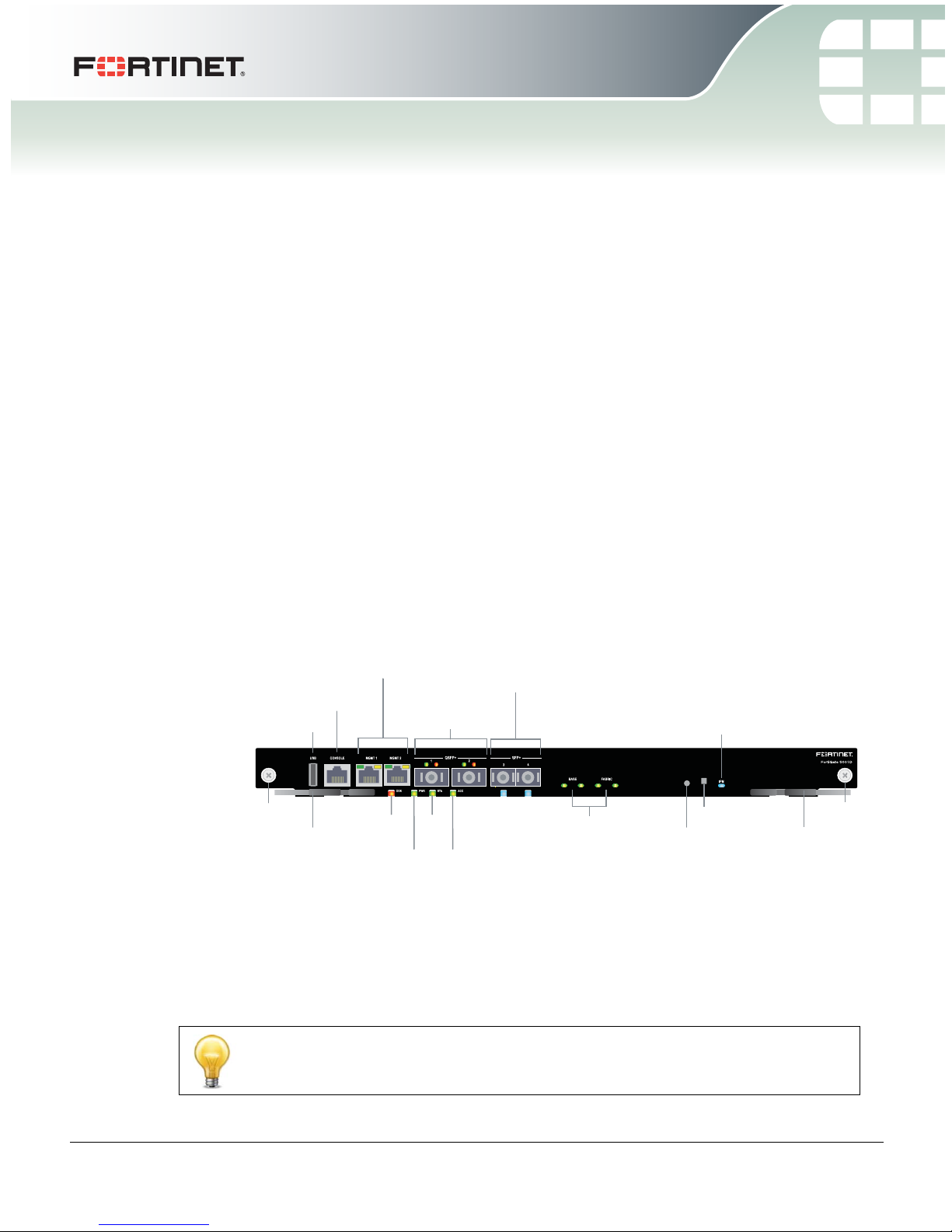
MGMT 1 and MGMT 2
10/100/1000 Copper
Management Interfaces
3 and 4
10 Gig
SFP+ Network
Interfaces
Base and Fabric
network activity
LEDs
RJ-45
Console
Extraction
Lever
Retention
Screw
US B
Extraction
Lever
Retention
Screw
IPM
LED
(board
position)
OOS
LED
STA
LED
PWR
LED
ACC
LED
Factory Use
NMI Switch
1 and 2
40 Gig
QSFP+ Network
Interfaces
FortiGate-5001D security system
The FortiGate-5001D security system is a high-performance Advanced
Telecommunications Computing Architecture (ATCA) compliant FortiGate security system
that can be installed in any ATCA chassis that can provide sufficient power and cooling.
Fortinet’s FortiGate-5144C chassis is recommended because it has a 40-gigabit fabric
backplane and the FortiGate-5001D has 40-gigabit fabric interfaces. You can also install
the FortiGate-5001D in a FortiGate-5060 or FortiGate-5140B chassis; both of which have
10-gigabit fabric backplanes.
See the FortiGate-5000 Compatability Guide for up-to-date information about
FortiGate-5000 series chassis and other components that are compatible with the
FortiGate-5001D.
The FortiGate-5001D security system contains two front panel 40-gigabit QSFP+
interfaces, two front panel 10-gigabit SFP+ interfaces, two base backplane 1-gigabit
interfaces, and two fabric backplane 40-gigabit interfaces. The front panel SFP+
interfaces can also operate as 1-gigabit SFP interfaces. Use the front panel interfaces for
connections to your networks and the backplane interfaces for communication across
the ATCA chassis backplane. The FortiGate-5001D also includes two front panel RJ45
10/100/1000 management Ethernet interfaces, one RJ45 front panel serial console port,
and one front panel USB port.
Figure 1: FortiGate-5001D front panel
The FortiGate-5001D front panel QSFP+ 40-gigabit, SFP+ 10-gigabit interfaces and
fabric backplane interfaces also provide NP6-accelerated network processing for eligible
traffic passing through these interfaces.
You can also configure two or more FortiGate-5001D boards to create a high availability
(HA) cluster using the base or fabric backplane interfaces for HA heartbeat
communication through the chassis backplane, leaving front panel interfaces available
for network connections.
In most cases the base backplane interfaces are used for HA heartbeat communication
and the fabric backplane interfaces are used for data communication.
01-500-0242101-20151109 5
http://docs.fortinet.com/
FortiGate-5001D Security System Guide
Page 6

Front panel components FortiGate-5001D security system
The FortiGate-5001D board also supports high-end FortiGate features including 802.1Q
VLANs, multiple virtual domains, 802.3ad aggregate interfaces, and FortiOS Carrier.
The FortiGate-5001D board includes the following features:
• Two front panel QSFP+ 40-gigabit interfaces (port1 and port2) accelerated by
FortiASIC NP6 network processors. port1 and port2 can each be split into four
10-gigabit ports using the config system global set split-port command.
• Two front panel SFP+ 10-gigabit interfaces (port3 and port4) also accelerated by
FortiASIC NP6 network processors. Can also be configured as SFP 1-gigabit
interfaces.
• Two front panel 10/100/1000Base-T copper 1-gigabit management ethernet
interfaces (mgmt1 and mgmt2).
• Two base backplane 1-gigabit interfaces (base1 and base2) for HA heartbeat
communications across the FortiGate-5000 chassis base backplane.
• Two fabric backplane 40-gigabit interfaces (fabric1 and fabric2) for data
communications across the FortiGate-5000 chassis fabric backplane.
• Two NP6 network processors that accelerate traffic on the interfaces port1, port2,
port3, port4, fabirc1, and fabric2.
• Four CP8 content processors that accelerate IPS, SSL VPN, and IPsec VPN.
• Internal 200 GByte SSD for storing log messages, DLP archives, historic reports, IPS
packet archiving, file quarantine, WAN Optimization byte caching and web caching.
• One RJ-45 RS-232 serial console connection.
•1 USB connector.
• NMI switch for troubleshooting as recommended by Fortinet Support.
• Mounting hardware.
• LED status indicators.
Front panel components
From the FortiGate-5001D front panel you can view the status of the front panel LEDs to
verify that the board is functioning normally. You also connect the FortiGate-5001D board
to your 40-gigabit network using the front panel QSFP+ connectors and to your
10-gigabit network using the front panel SFP+ or SFP connectors. The front panel also
includes two Ethernet management interfaces, an RJ-45 console port for connecting to
the FortiOS CLI and a USB port. The USB port can be used with any USB key for backing
up and restoring configuration files.
LEDs
Ports 1 and 2 can operate in 40-gigabit mode or 4 x 10-gigabit mode. The LEDs function
differently in each mode
Table 1: FortiGate-5001D Port 1 and 2 LEDs (40-gigabit mode)
Green LED (left) Amber LED (right) Description
On Off The correct cable is connected to the
Off Off No link is established.
interface and the connected equipment has
power.
6 01-500-0242101-20151109
FortiGate-5001D Security System Guide
http://docs.fortinet.com/
Page 7

FortiGate-5001D security system Front panel components
Table 2: FortiGate-5001D Port 1 and 2 LEDs (4 x 10-gigabit mode)
Green LED (left) Amber LED (right) Description
Flashing On The correct cable is connected to the
interface and the connected equipment has
power and all 10-gigabit connections are
connected.
Flashing Flashing The correct cable is connected to the
interface and the connected equipment has
power and only some of the 10-gigabit
connections are connected.
Off Off No link is established.
Table 3: Other FortiGate-5001D LEDs
LED State Description
Green The correct cable is connected to the interface and the
connected equipment has power.
3 and 4
Flashing
Network activity at the interface.
Green
Off No link is established.
Off Fabric backplane interface 1 or 2 (fabric1 or fabric2) is
connected at 10 Gbps.
Fabric 1 and 2
Flashing
Green
Network activity at fabric backplane interface 1 or 2
(fabric1 or fabric2).
Green Base backplane interface 1 or 2 (base1 or base2) is
connected at 1 Gbps.
Base 1 and 2
Flashing
Green
Network activity at base backplane interface 1 or 2
(base1 or base2).
Off Normal operation.
OOS
(Out of Service)
Amber A fault condition exists and the FortiGate-5001D blade
is out of service (OOS). This LED may also flash very
briefly during normal startup.
PWR (Power) Green The FortiGate-5001D board is powered on.
On The FortiGate-5001D board is powered on.
STA (Status)
Flashing
Green
The FortiGate-5001D is starting up. If this LED is
flashing at any time other than system startup, a fault
condition may exist.
FortiGate-5001D Security System Guide
01-500-0242101-20151109 7
http://docs.fortinet.com/
Page 8

Front panel components FortiGate-5001D security system
Table 3: Other FortiGate-5001D LEDs (Continued)
LED State Description
ACC (Disk
activity)
MGMT 1
and
MGMT 2
IPM
Link/Act
(Left
LED)
Speed
(Right
LED)
Off or
Flashing
green
The ACC LED flashes green when the FortiGate-5001D
board accesses the FortiOS flash disk. The FortiOS
flash disk stores the current FortiOS firmware build and
configuration files. The system accesses the flash disk
when starting up, during a firmware upgrade, or when
an administrator is using the CLI or GUI to change the
FortiOS configuration. Under normal operating
conditions this LED flashes occasionally, but is mostly
off.
Solid
Green
Indicates the management interface (mgmt1 or mgmt2)
is connected with the correct cable and the attached
network device has power.
Blinking
Indicates network traffic on this interface.
Green
Off No Link
Green Connection at 1 Gbps.
Amber Connection at 100 Mbps.
Off Connection at 10 Mbps.
Blue The FortiGate-5001D board is ready to be hot-swapped
(removed from the chassis). If the IPM light is blue and
no other LEDs are lit the FortiGate-5001D board has lost
power
Flashing
Blue
The FortiGate-5001D board is changing from hot swap
to running mode or from running mode to hot swap. This
happens when the FortiGate-5001D board is starting up
or shutting down.
Off Normal operation. The FortiGate-5001D board is in
contact with the chassis backplane.
Connectors
Table 4: FortiGate-5001D connectors
Connector Type Speed Protocol Description
CONSOLE
1 and 2
3 and 4
8 01-500-0242101-20151109
RJ-45 9600 bps
8/N/1
QSFP+ (40
gigabit),
40-gigabit full
10-gigabit full
SFP+ (10
gigabit)
SFP+ (10
gigabit) or
SFP (1
10-gigabit full
1-gigabit auto
1-gigabit full
gigabit)
RS-232
serial
Serial connection to the
command line interface.
Ethernet 40-gigabit QSFP+ connection to
40-gigabit networks or 10-gigabit
SFP+ connection to 10-gigabit
networks. Quad small form-factor
pluggable transceiver.
Ethernet 10-gigabit SFP+ connection to
10-gigabit networks or 1-gigabit
SFP connection to 1-gigabit
networks. Small form-factor
pluggable transceiver.
FortiGate-5001D Security System Guide
http://docs.fortinet.com/
Page 9

FortiGate-5001D security system Base backplane communication
Table 4: FortiGate-5001D connectors
Connector Type Speed Protocol Description
MGMT 1
and
MGMT 2
USB
RJ-45 10/100/1000
Base-T
USB USB key for firmware updates
NMI switch
When working with Fortinet Support to troubleshoot problems with the FortiGate-5001D
board you can use the front panel non-maskable interrupt (NMI) switch to assist with
troubleshooting. Pressing this switch causes the software to dump registers/backtraces
to the console. After the data is dumped the board reboots. While the board is rebooting,
traffic is temporarily blocked. The board should restart normally and traffic can resume
once its up and running.
Base backplane communication
The FortiGate-5001D base backplane 1-gigabit interfaces (base1 and base2) are typically
used for HA heartbeat or other management communication between FortiGate-5001D
boards installed in the same or in different FortiGate-5000 series chassis. You can also
configure FortiGate-5001D boards to use the base backplane interfaces for data
communication between FortiGate boards. To support base backplane communications
your FortiGate-series chassis must include one or more FortiSwitch or
FortiController-5000 series or other 1-gigabit base backplane switches installed in the
chassis in base slots 1 and 2.
For information about FortiSwitch and FortiController-5000 series boards, see the
FortiGate-5000 page of the Fortinet Technical Documentation website.
Ethernet Copper 1-gigabit connection to
10/100/1000Base-T copper
networks for management or
system administration.
and configuration backup.
Fabric backplane communication
The FortiGate-5001D fabric backplane interfaces (fabric1 and fabric2) are typically used
for data communication between FortiGate-5001D boards installed in the same or in
different FortiGate-5000 series chassis. These interfaces can operate as 40-gigabit or
10-gigabit interfaces
To support 40-gigabit fabric backplane communications your FortiGate-5000 series
chassis must include one or more FortiController-5903C boards or other 40-gigabit fabric
backplane switching boards installed in the chassis in fabric slots 1 and 2.
To support 10-gigabit fabric backplane communications your FortiGate-5000 series
chassis must include one or more FortiSwitch-5003B or FortiController-5903C boards or
other 10-gigabit fabric backplane switching boards installed in the chassis in fabric slots
1 and 2.
For information about FortiSwitch and FortiController-5000 series boards, see the
FortiGate-5000 page of the Fortinet Technical Documentation website.
FortiGate-5001D Security System Guide
01-500-0242101-20151109 9
http://docs.fortinet.com/
Page 10
Accelerated packet forwarding and policy enforcement (NP6 network processors) FortiGate-5001D security system
Accelerated packet forwarding and policy enforcement (NP6
network processors)
The FortiGate-5001D board includes two NP6 processors and an integrated switch fabric
that provides fastpath acceleration by offloading communication sessions from the
FortiGate CPU. All traffic from the front panel and backplane interfaces can be
accelerated. The result is enhanced network performance provided by the NP6 processor
plus the network processing load is removed from the CPU. The NP6 processor can also
handle some CPU intensive tasks, like IPsec VPN encryption/decryption. Because of the
integrated switch fabric, all sessions are fast-pathed and accelerated.
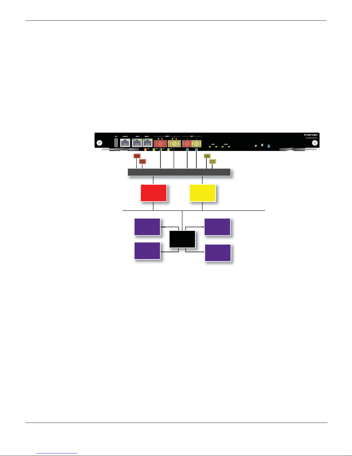
Figure 2: FortiGate-5001D NP6 to interface mapping
fabric1
base1
Integrated Switch Fabric
FortiASIC
NP6
CP8
CPU
CP8
FortiASIC
fabric2
base2
NP6
System Bus
CP8
CP8
The FortiGate-5001D features two NP6 processors.
• port1, port3, fabric1 and base1 share connections to the first NP6 processor.
• port2, port4, fabric2 and base2 share connections to the second NP6 processor.
Accelerated IPS, SSL VPN, and IPsec VPN (CP8 content
processors)
The FortiGate-5001D board includes four CP8 processors that provide the following
performance enhancements:
• Over 10Gbps throughput IPS content processor for packet content matching with
signatures
10 01-500-0242101-20151109
FortiGate-5001D Security System Guide
http://docs.fortinet.com/
Page 11

FortiGate-5001D security system Splitting the FortiGate-5001D front panel port1 and port2 interfaces
• High performance VPN bulk data engine
• IPSEC and SSL/TLS protocol processor
• DES/3DES/AES in accordance with FIPS46-3/FIPS81/FIPS197
• ARC4 in compliance with RC4
• MD5/SHA-1/SHA256 with RFC1321 and FIPS180
• HMAC in accordance with RFC2104/2403/2404 and FIPS198
• Key Exchange Processor support high performance IKE and RSA computation
• Public key exponentiation engine with hardware CRT support
• Primarily checking for RSA key generation
• Handshake accelerator with automatic key material generation
• Random Number generator compliance with ANSI X9.31
• Sub public key engine (PKCE) to support up to 4094 bit operation directly
• Message authentication module offers high performance cryptographic engine for
calculating SHA256/SHA1/MD5 of data up to 4G bytes (used by any application like
WAN opt.)
Splitting the FortiGate-5001D front panel port1 and port2
interfaces
You can use the following command to split the 40-gigabit front panel port1 interface into
a 4 x 10-gigabit interface:
config system global
set split-port port1
end
The FortiGate-5001D reboots and when it does you can see four new interfaces named
port1/1, port1/2, port1/3, and port1/4.
FortiGate-5001D Security System Guide
01-500-0242101-20151109 11
http://docs.fortinet.com/
Page 12

Splitting the FortiGate-5001D front panel port1 and port2 interfaces FortiGate-5001D security system
12 01-500-0242101-20151109
FortiGate-5001D Security System Guide
http://docs.fortinet.com/
Page 13

FortiGate-5001D
Hardware installation
Before use, the FortiGate-5001D board must be correctly inserted into an Advanced
Telecommunications Computing Architecture (ATCA) chassis that can provide sufficient
power and cooling.
This section describes:
• Installing QSFP+ and SFP+ transceivers
• Changing FortiGate-5001D SW6 switch settings
• FortiGate-5001D mounting components
• Inserting a FortiGate-5001D board
• Shutting down and removing a FortiGate-5001D board
• Power cycling a FortiGate-5001D board
• Installing QSFP+ and SFP+ transceivers
• Troubleshooting
Installing QSFP+ and SFP+ transceivers
You must install QSFP+ transceivers to connect the FortiGate-5001D front panel port1
and port2 interfaces to a 40-gigabit network. The QSFP+ transceivers are inserted into
cage sockets numbered 1 and 2 on the FortiGate-5001D front panel. You can install the
QSFP+ transceivers before or after inserting the FortiGate-5001D board into a chassis.
You must install SR SFP+ transceivers for normal operation of the FortiGate-5001D front
panel port3 and port4 interfaces. The FortiGate-5001D ships with two SR SFP+
transceivers. You can also configure front panel interfaces to operate at 1-gigabit and
install SFP transceivers. You can install the transceivers before or after inserting the
FortiGate-5001D board into a chassis.
You can install the following types of transceivers for connectors 3 and 4:
• SFP+ SR (10 gigabits)
• SFP+ LR (10 gigabits)
• SFP (1gigabit)
To install QSFP+, SFP+ or SFP transceivers
To complete this procedure, you need:
• A FortiGate-5001D board
• Two or QSFP+, SFP+ or SFP transceivers
• An electrostatic discharge (ESD) preventive wrist or ankle strap with connection cord
FortiGate-5001D boards must be protected from static discharge and physical shock.
Only handle or work with FortiGate-5001D boards at a static-free workstation. Always
wear a grounded electrostatic discharge (ESD) preventive wrist strap when handling
FortiGate-5001D boards.
FortiGate-5001D Security System Guide
01-500-0242101-20151109 13
http://docs.fortinet.com/
Page 14
Changing FortiGate-5001D SW6 switch settings Hardware installation
1 Attach the ESD wrist strap to your wrist and to an available ESD socket or wrist strap
terminal.
2 Remove the caps from the cage sockets on the FortiGate-5001D front panel.
Handling the QSFP+, SFP+ and SFP transceivers by holding the release latch can
damage the connector. Do not force transceivers into their cage slots. If the transceiver
does not easily slide in and click into place, it may not be aligned correctly. If this
happens, remove the transceiver, realign it and slide it in again.
3 Hold the sides of the transceiver and slide it into the cage socket until it clicks into
place.
Changing FortiGate-5001D SW6 switch settings
You should only change the SW6 switch setting if are required to install the
FortiGate-5001D board in a chassis that does not contain a functioning shelf manager.
The factory default SW6 setting is required for most uses of the FortiGate-5001D.
The SW6 switch on the FortiGate-5001D board can be set to operate the
FortiGate-5001D in standalone mode (without a shelf manager) or in normal mode in a
chassis with a shelf manager. The switch is factory set by Fortinet so that you can install
the FortiGate-5001D in normal mode in a chassis that includes an operating shelf manger
(such as a FortiGate-5000 series chassis).
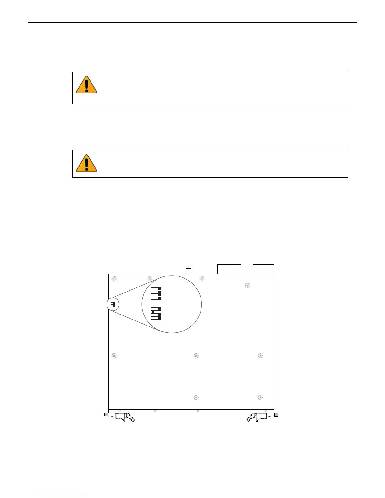
The top of the FortiGate-5001D board is covered with a metal panel. The printed circuit
board is under the metal panel. SW6 is located on the printed circuit board and is
accessible from the left side of the board under the metal panel as shown in Figure 3.
Figure 3: Location of SW6 on the FortiGate-5001D board
SW6
Normal Mode
3421
(Factory Default)
SW
3421
ON
ON
SW6
ON
Standalone Mode
3421
(No Shelf Manager)
Location of SW6
FortiGate-5001D
14 01-500-0242101-20151109
Front Faceplate
FortiGate-5001D Security System Guide
http://docs.fortinet.com/
Page 15

Hardware installation Changing FortiGate-5001D SW6 switch settings
Normal Mode
(Factory Default)
ON
SW6
3421
ON
SW6
3421
Standalone Mode
(No Shelf Manager)
ON
SW6
3421
ON
SW6
3421
Figure 4: Factory default shelf manager mode setting for SW6
By default a FortiGate-5001D board will not start up if the board is installed in a chassis
that does not contain a shelf manager or that contains a shelf manager that is not
operating. Before installing a FortiGate-5001D in a chassis that does not contain an
operating shelf manager you must change the SW6 switch setting to match Figure 5.
Figure 5: Standalone mode setting for SW6
In all cases you should confirm that you have the correct SW6 setting before installing the
board in a chassis.
Table 5: FortiGate-5001D SW6 settings
Correct
Chassis
FortiGate-5140B or 5060 or a
ATCA chassis with a compatible
operating shelf manager (factory
default shelf manager mode).
Any ATCA chassis without an
operating shelf manager
(standalone mode).
If the shelf manager in a FortiGate-5000 series chassis is missing or not functioning,
FortiGate-5001D boards with factory default SW6 settings will not start up.
To change or verify the SW6 switch setting
To complete this procedure, you need:
• A FortiGate-5001D board
• A tool for changing the SW6 switch setting (optional)
• An electrostatic discharge (ESD) preventive wrist strap with connection cord
FortiGate-5001D boards must be protected from static discharge and physical shock.
Only handle or work with FortiGate-5001D boards at a static-free workstation. Always
wear a grounded electrostatic discharge (ESD) preventive wrist strap when handling
FortiGate-5001D boards.
SW6
Setting
Result of wrong jumper setting
Shelf manager cannot find
FortiGate-5001D board. No shelf
manager information about the
FortiGate-5001D board available.
FortiGate-5001D board will not start
up.
FortiGate-5001D Security System Guide
01-500-0242101-20151109 15
http://docs.fortinet.com/
Page 16

FortiGate-5001D mounting components Hardware installation
Closed
Open
Alignment
Pin
Retention
Screw
Lock
Handle
Alignment Pin
Retention
Screw
Lock
Handle
Handle
Hook
Alignment Pin
Retention
Screw
Lock
Hook
Alignment
Pin
Retention
Screw
Lock
Handle
1 Attach the ESD wrist strap to your wrist and to an available ESD socket or wrist strap
terminal.
2 If you have installed the FortiGate-5001D board in a chassis, remove it.
For removal instructions, see “Shutting down and removing a FortiGate-5001D board”
on page 19.
3 Use Figure 3 on page 14 to locate SW6 on the FortiGate-5001D board.
4 If required, change SW6 to the correct setting.
5 Insert the FortiGate-5001D board into a chassis and verify that the board starts up
and operates correctly.
For inserting instructions, see “Inserting a FortiGate-5001D board” on page 17.
FortiGate-5001D mounting components
To install a FortiGate-5001D board you slide the board into an open slot in the front of an
ATCA chassis and then use the mounting components to lock the board into place in the
slot. When locked into place and positioned correctly the board front panel is flush with
the chassis front panel. The board is also connected to the chassis backplane.
FortiGate-5001D boards are horizontal when inserted into a FortiGate-5060 chassis and
vertical when inserted into a FortiGate-5140 chassis. The inserting and removing
procedures are the same in either case. For clarity the descriptions in this document
refer to the left (top) and right (bottom) mounting components.
To position the board correctly you must use the mounting components shown in
Figure 6 for the right (bottom) side of the front panel. The mounting components on the
left (top) side of the FortiGate-5001D front panel are the same but reversed. The
FortiGate-5001D mounting components align the board in the chassis slot and are used
to insert and eject the board from the slot.
Figure 6: FortiGate-5001D right (bottom) mounting components
16 01-500-0242101-20151109
FortiGate-5001D Security System Guide
http://docs.fortinet.com/
Page 17
Hardware installation Inserting a FortiGate-5001D board
The FortiGate-5001D handles align the board in the chassis slot and are used to insert
and eject the board from the slot. The right (bottom) handle activates a microswitch that
turns on or turns off power to the board. When the right (bottom) handle is open the
microswitch is off and the board cannot receive power. When the right (bottom) handle is
fully closed the microswitch is on and if the board is fully inserted into a chassis slot the
board can receive power.
You can use front panel reset switch to cycle the power and reset the board without
removing the board from the chassis. See “Power cycling a FortiGate-5001D board” on
page 21.
Inserting a FortiGate-5001D board
The FortiGate-5001D board must be fully installed in a chassis slot, with the handles
closed and locked and retention screws fully tightened for the FortiGate-5001D board to
receive power and operate normally. If the FortiGate-5001D board is not receiving power,
the IPM LED glows solid blue and all other LEDs remain off. See “Front panel
components” on page 6.
It is important to carefully seat the FortiGate-5001D board all the way into the chassis, to
avoid using excessive force on the handles, and to make sure that the handles are
properly locked. Only then will the FortiGate-5001D board power-on and start up
correctly.
FortiGate-5001D boards are hot swappable. The procedure for inserting
a FortiGate-5001D board into a chassis slot is the same whether or not the chassis is
powered on.
To insert a FortiGate-5001D board into a chassis slot
Do not carry the FortiGate-5001D board by holding the handles or retention screws.
When inserting or removing the FortiGate-5001D board from a chassis slot, handle the
board by the front panel. The handles are not designed for carrying the board. If the
handles become bent or damaged the FortiGate-5001D board may not align correctly in
the chassis slot.
To complete this procedure, you need:
• A FortiGate-5001D board
• An ATCA chassis with an empty slot
• An electrostatic discharge (ESD) preventive wrist strap with connection cord
FortiGate-5001D boards must be protected from static discharge and physical shock.
Only handle or work with FortiGate-5001D boards at a static-free workstation. Always
wear a grounded electrostatic discharge (ESD) preventive wrist strap when handling
FortiGate-5001D boards.
1 Attach the ESD wrist strap to your wrist and to an available ESD socket or wrist strap
terminal.
2 If required, remove the protective metal frame that the FortiGate-5001D board has
been shipped in.
3 Insert the FortiGate-5001D board into the empty slot in the chassis.
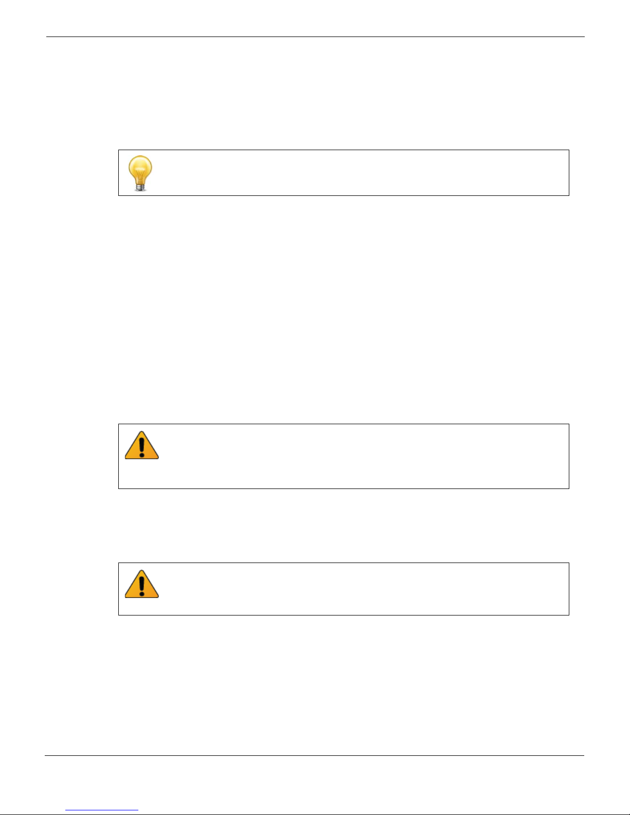
4 Unlock the handles by squeezing the handle locks.
FortiGate-5001D Security System Guide
01-500-0242101-20151109 17
http://docs.fortinet.com/
Page 18
Inserting a FortiGate-5001D board Hardware installation
5 Open the handles to their fully open positions.
To avoid damaging the lock, make sure you squeeze the handles fully to unlock them
before opening. The handles should pop easily out of the board front panel.
Alignment Pin
Alignment Pin
Handle
Open
Handle
Lock
6 Carefully guide the board into the chassis using the rails in the slot.
Insert the board by applying moderate force to the front faceplate (not the handles) to
slide the board into the slot. The board should glide smoothly into the chassis slot. If
you encounter any resistance while sliding the board in, the board could be aligned
incorrectly. Pull the board back out and try inserting it again.
7 Slide the board in until the alignment pins are inserted half way into their sockets in
the chassis.
8 Turn both handles to their fully-closed positions.
The handles should hook into the sides of the chassis slot. Closing the handles draws
the FortiGate-5001D board into place in the chassis slot and into full contact with the
chassis backplane. The FortiGate-5001D front panel should be in contact with the
chassis front panel and both handles should lock into place.
As the handles closed power is supplied to the board. If the chassis is powered on the
IPM LED starts flashing blue. If the board is aligned correctly, inserted all the way into
the slot, and the handles are properly closed the IPM LED flashes blue for a few
seconds. At the same time the STATUS LED flashes green, the interface LEDs flash
amber, and the ACC LED starts flashing green. After a few seconds the IPM LED goes
out and the FortiGate-5001D firmware starts up. During start up the STATUS LED may
continue to flash green. Once the board has started up and is operating correctly, the
front panel LEDs are lit as described in Ta bl e 6 .
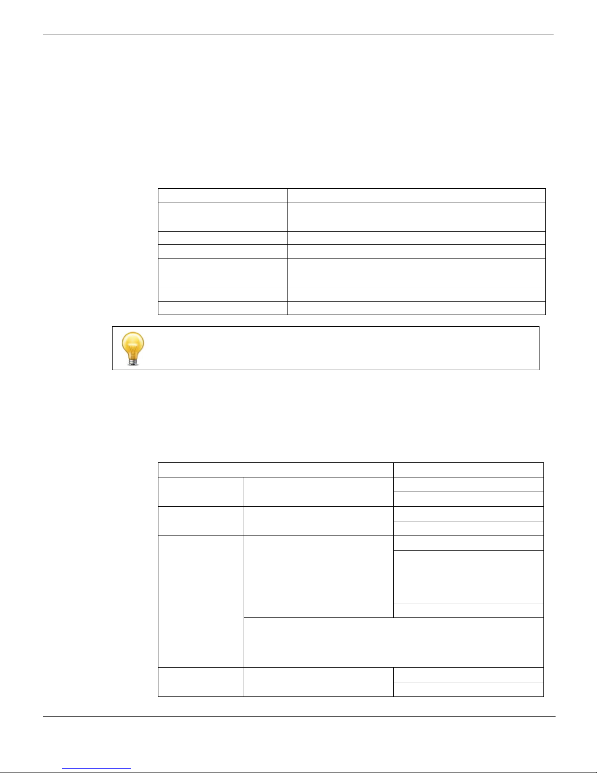
Table 6: FortiGate-5001D normal operating LEDs
LED State
OOS Off
PWR Green
STA Off
ACC
IPM Off
If the board has not been inserted properly the IPM LED changes to solid blue and all
other LEDS turn off. If this occurs, open the handles, slide the board part way out, and
repeat the insertion process.
18 01-500-0242101-20151109
Off (Or flashing green when the system accesses the
FortiGate-5001D flash disk.)
FortiGate-5001D Security System Guide
http://docs.fortinet.com/
Page 19

Hardware installation Shutting down and removing a FortiGate-5001D board
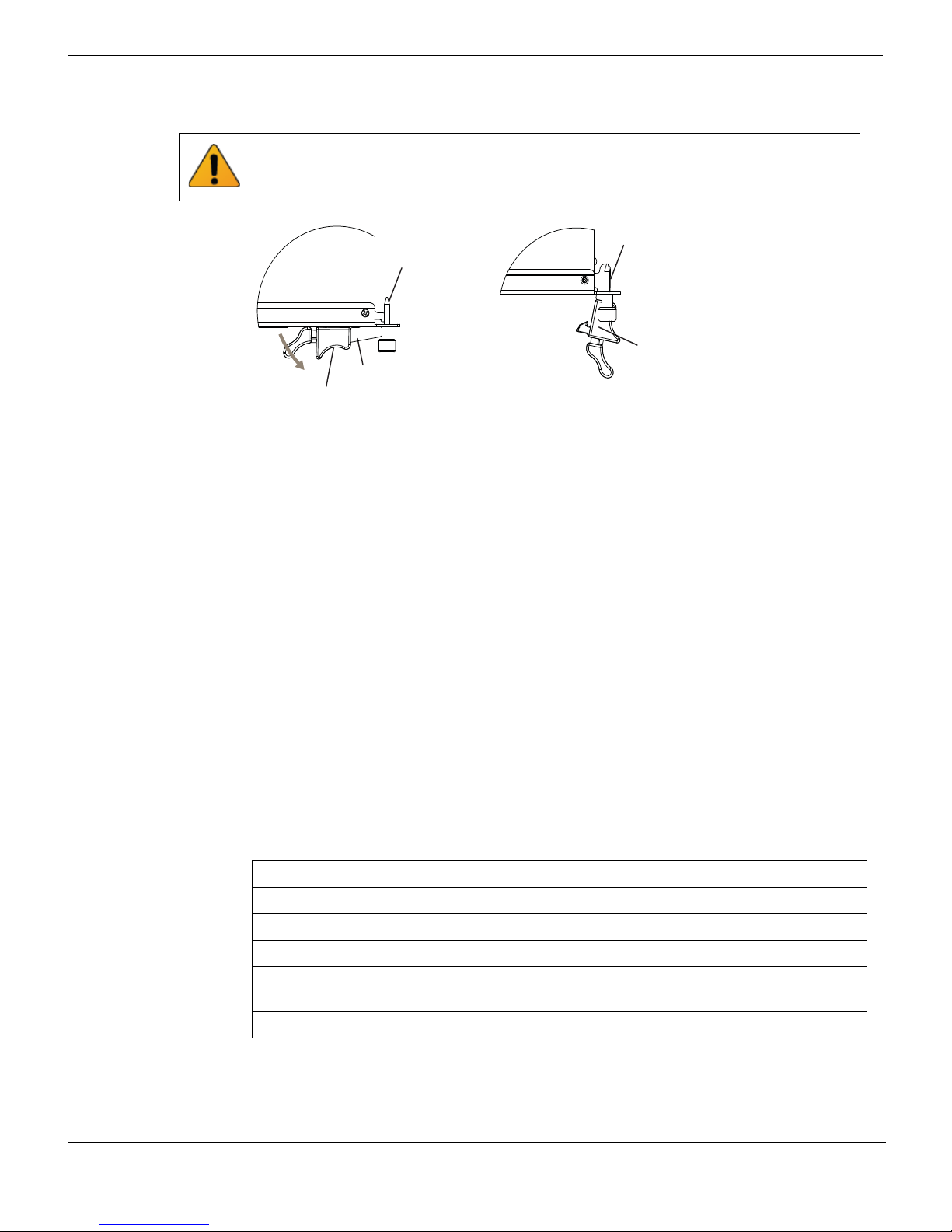
9 Once the board is inserted correctly, fully tighten the retention screws to lock the
FortiGate-5001D board into position in the chassis slot.
Retention
Screw
Tighten
Shutting down and removing a FortiGate-5001D board
The following procedure describes how to correctly use the FortiGate-5001D mounting
components described in “FortiGate-5001D mounting components” on page 16 to
remove a FortiGate-5001D board from an ATCA chassis slot.
To avoid potential hardware problems, always shut down the FortiGate-5001D operating
system (FortiOS) properly before power cycling the FortiGate-5001D board.
FortiGate-5001D boards are hot swappable. The procedure for removing
a FortiGate-5001D board from a chassis slot is the same whether or not the chassis is
powered on.
To remove a FortiGate-5001D board from a chassis slot
Do not carry the FortiGate-5001D board by holding the handles or retention screws.
When inserting or removing the FortiGate-5001D board from a chassis slot, handle the
board by the front panel. The handles are not designed for carrying the board. If the
handles become bent or damaged the FortiGate-5001D board may not align correctly in
the chassis slot.
To complete this procedure, you need:
• An ATCA chassis with a FortiGate-5001D board installed
• An electrostatic discharge (ESD) preventive wrist strap with connection cord
FortiGate-5001D boards must be protected from static discharge and physical shock.
Only handle or work with FortiGate-5001D boards at a static-free workstation. Always
wear a grounded electrostatic discharge (ESD) preventive wrist strap when handling
FortiGate-5001D boards.
1 Shut down the operating system running on the FortiGate-5001D board. For example:
• From the web-based manager, go to System > Status and from the Unit Operation
widget, select Shutdown and then select OK.
• From the CLI enter
execute shutdown
2 Attach the ESD wrist strap to your wrist and to an available ESD socket or wrist strap
terminal.
3 Disconnect all cables from the FortiGate-5001D board, including all network cables,
the console cable, and any USB cables or keys.
FortiGate-5001D Security System Guide
01-500-0242101-20151109 19
http://docs.fortinet.com/
Page 20
Shutting down and removing a FortiGate-5001D board Hardware installation
Handle
Alignment Pin
Open
Alignment Pin
Lock
Handle
Fully Closed
and Locked
Alignment Pin
Handle
Close
Alignment Pin
Handle
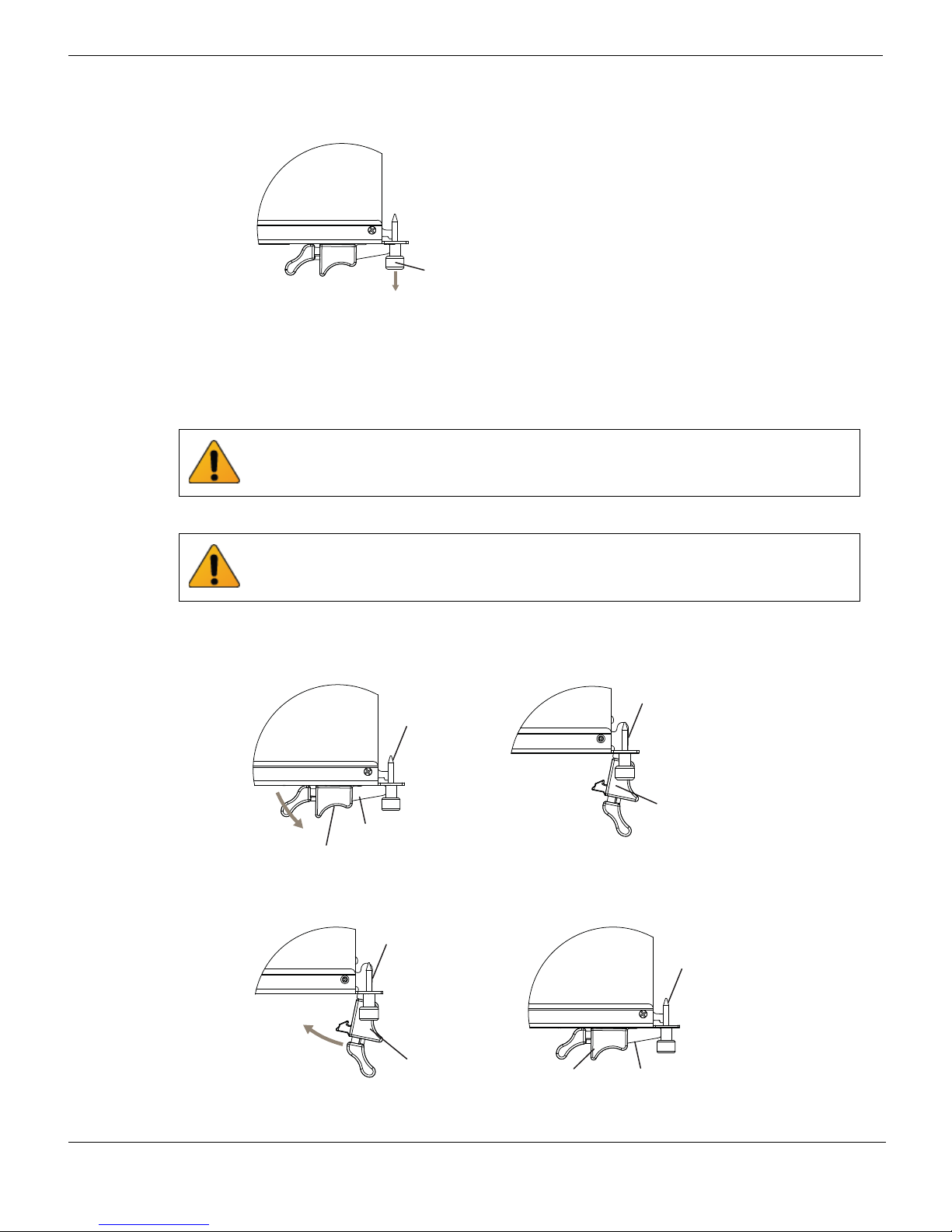
4 Fully loosen the retention screws on the FortiGate-5001D front panel.
Retention
Screw
Loosen
5 Unlock the handles by squeezing the handle locks.
6 Slowly open both handles a small amount (about 8 degrees) until the IPM LED flashes
blue.
7 Keep the handles in this position until the IPM LED stops flashing and becomes solid
blue.
Waiting for the IPM LED to change to solid blue makes sure that the board software
shutdowns completely before disconnecting it from backplane power.
8 Open the handles to their fully open positions.
To avoid damaging the lock, make sure you squeeze the handles fully to unlock them
before opening. The handles should pop easily out of the board front panel.
You need to open the handles with moderate pressure to eject the board from the
chassis. Pivoting the handles turns off the microswitch, turns off all LEDs, and ejects
the board from the chassis slot.
9 Pull the board about half way out.
10 Turn both handles to their fully-closed positions.
20 01-500-0242101-20151109
FortiGate-5001D Security System Guide
http://docs.fortinet.com/
Page 21

Hardware installation Power cycling a FortiGate-5001D board
11 Carefully slide the board completely out of the slot.
12 Re-attach the protective metal frame before shipping or storing the FortiGate-5001D
board.
Power cycling a FortiGate-5001D board
This section describes how to cycle the power on a FortiGate-5001D board by opening
the right handle (the lower handle when the board is installed vertically in a
FortiGate-5140 chassis) to activate a switch that cycles the power without removing the
board from the chassis. The steps recommend loosening the retention screws before
opening the handle to allow the handle to toggle the switch. During this process the
board may move out a small amount (less than 1 mm).
To avoid potential hardware problems, always shut down the FortiGate-5001D operating
system properly before power cycling the FortiGate-5001D board.
To power cycle a FortiGate-5001D board without fully removing the board from the
chassis
To complete this procedure, you need:
• An ATCA chassis with a FortiGate-5001D board installed
• An electrostatic discharge (ESD) preventive wrist strap with connection cord
FortiGate-5001D boards must be protected from static discharge and physical shock.
Only handle or work with FortiGate-5001D boards at a static-free workstation. Always
wear a grounded electrostatic discharge (ESD) preventive wrist strap when handling
FortiGate-5001D boards.
1 Shut down the operating system running on the FortiGate-5001D board. For example:
• From the web-based manager, go to the Unit Operation dashboard widget, select
Shutdown and then select OK.
• From the CLI enter
execute shutdown
2 Attach the ESD wrist strap to your wrist and to an available ESD socket or wrist strap
terminal.
3 Fully loosen the retention screws on the FortiGate-5001D front panel.
4 Unlock both handles by squeezing the handle locks.
Unlock
Handle
5 Slowly open both handles a small amount (about 8 degrees) until the IPM LED flashes
blue.
6 Keep the handles in this position until the IPM LED stops flashing and becomes solid
blue.
FortiGate-5001D Security System Guide
01-500-0242101-20151109 21
http://docs.fortinet.com/
Page 22

Troubleshooting Hardware installation
7 After 10 seconds snap both handles back into place.
The board powers up, the LEDs light and in a few minutes the FortiGate-5001D board
operates normally.
8 Fully tighten the retention screws to lock the FortiGate-5001D board into position in
the chassis slot.
Troubleshooting
This section describes some common troubleshooting topics.
FortiGate-5001D board does not start up
Shelf manager or firmware problems may prevent a FortiGate-5001D board from starting
up correctly.
Chassis with a shelf manager: no communication with shelf manager
If the FortiGate-5001D board is receiving power and the handles are fully closed and the
FortiGate-5001D still does not start up, the problem could be that the FortiGate-5001D
cannot communicate with the chassis shelf manager. This problem can only occur in an
ATCA chassis that contains a shelf manager.
To correct this problem power down and then restart the chassis. If you are operating a
FortiGate-5000 series chassis you can power down and then restart the chassis without
removing FortiGate-5000 series components.
All chassis: Firmware problem
If the FortiGate-5001D board is receiving power and the handles are fully closed, and you
have restarted the chassis and the FortiGate-5001D still does not start up, the problem
could be with FortiOS. Connect to the FortiGate-5001D console and try cycling the
power to the board. If the BIOS starts up, interrupt the BIOS startup and install a new
firmware image. If this does not solve the problem, contact Fortinet Customer Service
and Support.
FortiGate-5001D STA (status) LED is flashing during system operation
Normally, the FortiGate-5001D STA (status) LED is on when the FortiGate-5001D board is
operating normally. If this LED starts flashing while the board is operating, a fault
condition may exist. At the same time the FortiGate-5001D may stop processing traffic.
To resolve the problem you can try removing and reinserting the FortiGate-5001D board
in the chassis slot. Reloading the firmware may also help. If this does not solve the
problem there may have been a hardware failure or other problem. Contact Fortinet
Technical Support for assistance.
22 01-500-0242101-20151109
FortiGate-5001D Security System Guide
http://docs.fortinet.com/
Page 23

Hardware installation T roubleshooting
The FortiGate-5001D can’t join a FortiController-5903 SALB cluster and other
fabric backplane communication problems
In some SALB configurations and with some firmware builds you may have to manually
set the speeds of FortiGate-5001D interfaces that connect to the fabric blackplane (for
example, elbc-ctrl/1 and elbc-ctrl/2). Normally the speeds of these interfaces are set to
auto and normally this would work. But in some cases you have to set these interface
speeds to 40000full if the cluster is installed in a FortiGate-5144C chassis or 10000full if
the cluster is installed in a chassis with a 10-gbyte backplane (such as the FortiGate5060 of 5140B). If you have issues with the FortiGate-5001D communicating with the
fabric backplane you can use the following CLI command to change the speeds of these
interfaces:
To set the speed to be compatible with a 40-gbyte backplane:
config system interface
edit elbc-ctrl/1
set speed 40000full
next
edit elbc-ctrl/2
set speed 40000full
end
To set the speed to be compatible with a 10-gbyte backplane:
config system interface
edit elbc-ctrl/1
set speed 10000full
next
edit elbc-ctrl/2
set speed 10000full
end
FortiGate-5001D Security System Guide
01-500-0242101-20151109 23
http://docs.fortinet.com/
Page 24

Troubleshooting Hardware installation
24 01-500-0242101-20151109
FortiGate-5001D Security System Guide
http://docs.fortinet.com/
Page 25

FortiGate-5001D
Quick Configuration Guide
This section is a quick start guide to connecting and configuring a FortiGate-5001D
security system for your network.
Before using this chapter, your FortiGate-5000 series or compatible ATCA chassis should
be mounted and connected to your power system. In addition, your FortiGate-5001D
board should be inserted into the chassis and QSFP+ or SFP+ transceivers should be
installed. The FortiGate-5001D board should also be powered up and the front panel
LEDs should indicate that the board is functioning normally.
This chapter includes the following topics:
• Registering your Fortinet product
• Planning the configuration
• Choosing the configuration tool
• Factory default settings
• Configuring NAT/Route mode
• Configuring Transparent mode
• Upgrading FortiGate-5001D firmware
• FortiGate-5001D base backplane data communication
Registering your Fortinet product
Register your Fortinet product to receive Fortinet customer services such as product
updates and customer support. You must also register your product for FortiGuard
services such as FortiGuard Antivirus and Intrusion Prevention updates and for
FortiGuard Web Filtering and AntiSpam.
Register your product by visiting https://support.fortinet.com.
To register, enter your contact information and the serial numbers of the Fortinet products
that you or your organization have purchased. You can register multiple Fortinet products
in a single session without re-entering your contact information.
Planning the configuration
Before beginning to configure your FortiGate-5001D security system, you need to plan
how to integrate the system into your network. Your configuration plan depends on the
operating mode that you select: NAT/Route mode (the default) or Transparent mode.
NAT/Route mode
In NAT/Route mode, the FortiGate-5001D security system is visible to the networks that it
is connected to. Each interface connected to a network must be configured with an IP
address that is valid for that network. In many configurations, in NAT/Route mode all of
the FortiGate interfaces are on different networks, and each network is on a separate
subnet.
FortiGate-5001D Security System Guide
01-500-0242101-20151109 25
http://docs.fortinet.com/
Page 26

Planning the configuration Quick Configuration Guide
You would typically use NAT/Route mode when the FortiGate-5001D security system is
deployed as a gateway between private and public networks. In the default NAT/Route
mode configuration, the FortiGate-5001D security system functions as a firewall. Firewall
policies control communications through the FortiGate-5001D security system. No traffic
can pass through the FortiGate-5001D security system until you add firewall policies.
In NAT/Route mode, firewall policies can operate in NAT mode or in Route mode. In NAT
mode, the FortiGate firewall performs network address translation before IP packets are
sent to the destination network. In Route mode, no translation takes place.
Figure 7: Example FortiGate-5001D board operating in NAT/Route mode
Internal
network
Transparent mode
In Transparent mode, the FortiGate-5001D security system is invisible to the network. All
of the FortiGate-5001D interfaces are connected to different segments of the same
network. In Transparent mode you only have to configure a management IP address so
that you can connect to the FortiGate-5001D security system to make configuration
changes and so the FortiGate-5001D security system can connect to external services
such as the FortiGuard Distribution Network (FDN).
You would typically deploy a FortiGate-5001D security system in Transparent mode on a
private network behind an existing firewall or behind a router. In the default Transparent
mode configuration, the FortiGate-5001D security system functions as a firewall. No
traffic can pass through the FortiGate-5001D security system until you add firewall
policies.
port1
192.168.1.2
port2
204.23.1.2
FortiGate-5001D
board in NAT/Route
mode
NAT mode policies
controlling trafc
between internal
and extermal networks
26 01-500-0242101-20151109
FortiGate-5001D Security System Guide
http://docs.fortinet.com/
Page 27

Quick Configuration Guide Choosing the configuration tool
FortiGate-5001D
board in
Transparent mode
Internal
network
port1
Management
IP 192.168.1.99
port2
Transparent mode policies
controlling trafc
between internal
and extermal networks
192.168.1.1
Gateway to
public network
204.23.1.2
Figure 8: Example FortiGate-5001D board operating in Transparent mode
Choosing the configuration tool
You can use either the web-based manager or the Command Line Interface (CLI) to
configure the FortiGate board.
Web-based manager
The FortiGate-5001D web-based manager is an easy to use management tool. Use the
web-based manager to configure the FortiGate-5001D administrator password, the
interface addresses, the default gateway, and the DNS server addresses.
Requirements:
• An Ethernet connection between the FortiGate-5001D board and management
computer.
• Internet Explorer 6.0 or higher on the management computer.
Command Line Interface (CLI)
The CLI is a full-featured management tool. Use it to configure the administrator
password, the interface addresses, the default gateway, and the DNS server addresses.
Requirements:
• The serial connector that came packaged with your FortiGate-5001D board.
• Terminal emulation application (for example, HyperTerminal for Windows) on the
management computer.
FortiGate-5001D Security System Guide
01-500-0242101-20151109 27
http://docs.fortinet.com/
Page 28
Factory default settings Quick Configuration Guide
Factory default settings
The FortiGate-5001D unit ships with a factory default configuration. The default
configuration allows you to connect to and use the FortiGate-5001D web-based manager
to configure the FortiGate-5001D board onto the network. To configure the
FortiGate-5001D board onto the network you add an administrator password, change the
network interface IP addresses, add DNS server IP addresses, and, if required, configure
basic routing.
Table 7: FortiGate-5001D factory default settings
Operation Mode NAT/Route
Administrator Account
mgmt1 IP/Netmask 192.168.1.99/24
mgmt2 IP/Netmask 192.168.100.99/24
Default route
Primary DNS Server: 208.91.112.53
Secondary DNS Server: 208.91.112.52
User Name: admin
Password: (none)
Gateway: 192.168.100.1
Device: mgmt2
At any time during the configuration process, if you run into problems, you can reset the
FortiGate-5001D board to the factory defaults and start over. From the CLI enter
execute factory reset.
Configuring NAT/Route mode
Use Ta bl e 8 to gather the information you need to customize NAT/Route mode settings
for the FortiGate-5001D security system. You can use one table for each board to
configure.
Table 8: FortiGate-5001D board NAT/Route mode settings
Admin Administrator Password:
mgmt1
port1
port2
Default Route
DNS Servers
IP: _____._____._____._____
Netmask: _____._____._____._____
IP: _____._____._____._____
Netmask: _____._____._____._____
IP: _____._____._____._____
Netmask: _____._____._____._____
Device (Name of the Interface
connected to the external
network):
Default Gateway IP address: _____._____._____._____
The default route consists of the name of the interface connected
to an external network (usually the Internet) and the default gateway
IP address. The default route directs all non-local traffic to this
interface and to the external network.
Primary DNS Server: _____._____._____._____
Secondary DNS Server: _____._____._____._____
28 01-500-0242101-20151109
FortiGate-5001D Security System Guide
http://docs.fortinet.com/
Page 29

Quick Configuration Guide Configuring NAT/Route mode
Using the web-based manager to configure NAT/Route mode
1 Connect port1 of the FortiGate-5001D board to the same hub or switch as the
computer you will use to configure the FortiGate-5001D board.
If you cannot connect to port1, see “Using the CLI to configure NAT/Route mode” on
page 30.
2 Configure the management computer to be on the same subnet as the port1 interface
of the FortiGate-5001D board. To do this, change the IP address of the management
computer to 192.168.1.2 and the netmask to 255.255.255.0.
3 To access the FortiGate-5001D web-based manager, start Internet Explorer and
browse to https://192.168.1.99 (remember to include the “s” in https://).
4 Type admin in the Name field and select Login.
To change the admin administrator password
1 Go to System > Admin > Administrators.
2 Select Change Password for the admin administrator and enter a new password.
See the Fortinet Knowledge Base article Recovering lost administrator account
passwords if you forget or lose an administrator account password and cannot log into
your FortiGate-5001D unit.
To configure interfaces
1 Go to System > Network > Interface and edit each interface to configure.
2 Set the addressing mode for the interface. (See the online help for information.)
• For manual addressing, enter the IP address and netmask for the interface that you
added to Table 8 on page 28.
• For DHCP addressing, select DHCP and any required settings.
• For PPPoE addressing, select PPPoE and enter the username and password and
any other required settings.
To configure the Primary and Secondary DNS server IP addresses
1 Go to System > Network > DNS.
2 Enter the Primary and Secondary DNS IP addresses that you added to Tab le 8 on
page 28 as required and select Apply.
To configure the Default Gateway
1 Go to Router > Static > Static Route and Edit the static route.
2 Select the Device that you recorded above.
3 Set Gateway to the Default Gateway IP address that you added to Ta bl e 8 o n pa g e 28 .
4 Select OK.
FortiGate-5001D Security System Guide
01-500-0242101-20151109 29
http://docs.fortinet.com/
Page 30

Configuring NAT/Route mode Quick Configuration Guide
Using the CLI to configure NAT/Route mode
1 Use the serial cable supplied with your FortiGate-5001D board to connect the
FortiGate-5001D Console port to the management computer serial port.
2 Start a terminal emulation program (HyperTerminal) on the management computer.
Use these settings:
Baud Rate (bps) 9600, Data bits 8, Parity None, Stop bits 1, and Flow Control None.
3 At the Login: prompt, type admin and press Enter twice (no password required).
4 Change the administrator password.
config system admin
edit admin
set password <password>
end
See the Fortinet Knowledge Base article Recovering lost administrator account
passwords if you forget or lose an administrator account password and cannot log into
your FortiGate-5001D unit.
5 Configure the mgmt1, port1, and port1 interfaces to the settings that you added to
Table 8 on page 28.
config system interface
edit mgmt1
set ip <intf_ip>/<netmask_ip>
next
edit port1
set ip <intf_ip>/<netmask_ip>
next
edit port2
set ip <intf_ip>/<netmask_ip>
end
6 Configure the primary and secondary DNS server IP addresses to the settings that
you added to Table 8 on page 28.
config system dns
set primary <dns-server_ip>
set secondary <dns-server_ip>
end
7 Configure the default gateway to the setting that you added to Table 8 on page 28.
config router static
edit 1
set device <interface_name>
set gateway <gateway_ip>
end
30 01-500-0242101-20151109
FortiGate-5001D Security System Guide
http://docs.fortinet.com/
Page 31

Quick Configuration Guide Configuring Transparent mode
Configuring Transparent mode
Use Tab le 9 to gather the information you need to customize Transparent mode settings.
Table 9: Transparent mode settings
Admin Administrator Password:
IP: _____._____._____._____
Management
IP
Default Route
DNS Servers
Netmask: _____._____._____._____
The management IP address and netmask must be valid for
the network where you will manage the FortiGate-5001D unit.
Default Gateway IP address: _____._____._____._____
In Transparent mode the default route requires the default
gateway IP address. The default route directs all non-local
traffic to the external network.
Primary DNS Server: _____._____._____._____
Secondary DNS Server: _____._____._____._____
Using the web-based manager to configure Transparent mode
1 Connect port1 of the FortiGate-5001D board to the same hub or switch as the
computer you will use to configure the FortiGate-5001D board.
If you cannot connect to port1, see “Using the CLI to configure Transparent mode” on
page 32.
2 Configure the management computer to be on the same subnet as the port1 interface
of the FortiGate-5001D board. To do this, change the IP address of the management
computer to 192.168.1.2 and the netmask to 255.255.255.0.
3 To access the FortiGate-5001D web-based manager, start Internet Explorer and
browse to https://192.168.1.99 (remember to include the “s” in https://).
4 Type admin in the Name field and select Login.
To switch from NAT/Route mode to transparent mode
1 Go to System > Dashboard > Status and select the Change link beside Operation
Mode: NAT.
2 Set Operation Mode to Transparent.
3 Set the Management IP/Netmask to the settings that you added to Tabl e 9 on
page 31.
4 Set the default Gateway to the setting that you added to Table 9 on page 31.
To change the admin administrator password
1 Go to System > Admin > Administrators.
2 Select Change Password for the admin administrator and enter the password that you
added to Table 9 on page 31.
FortiGate-5001D Security System Guide
01-500-0242101-20151109 31
http://docs.fortinet.com/
Page 32

Upgrading FortiGate-5001D firmware Quick Configuration Guide
To change the management IP address
1 Go to System > Dashboard > Status and select the Change link beside Operation
Mode: Transparent.
2 Change the Management IP/Netmask to the address and netmask hat you added to
Table 9 on page 31 and select Apply.
To configure the Primary and Secondary DNS server IP addresses
1 Go to System > Network > DNS.
2 Enter the Primary and Secondary DNS IP addresses that you added to Tab le 9 on
page 31 as required and select Apply.
Using the CLI to configure Transparent mode
1 Use the serial cable supplied with your FortiGate-5001D board to connect the
FortiGate-5001D Console port to the management computer serial port.
2 Start a terminal emulation program (HyperTerminal) on the management computer.
Use these settings:
Baud Rate (bps) 9600, Data bits 8, Parity None, Stop bits 1, and Flow Control None.
3 At the Login: prompt, type admin and press Enter twice (no password required).
4 Change from NAT/Route mode to Transparent mode. Configure the Management IP
address and default gateway to the settings that you added to Table 9 on page 31.
config system settings
set opmode transparent
set manageip <mng_ip>/<netmask>
set gateway <gateway_ip>
end
5 Configure the primary and secondary DNS server IP addresses to the settings that
you added to Table 9 on page 31.
config system dns
set primary <dns-server_ip>
set secondary <dns-server_ip>
end
Upgrading FortiGate-5001D firmware
Fortinet periodically updates the FortiGate-5001D FortiOS firmware to include
enhancements and address issues. After you have registered your FortiGate-5001D
security system you can download FortiGate-5001D firmware from the support web site
http://support.fortinet.com.
Only FortiGate-5001D administrators (whose access profiles contain system read and
write privileges) and the FortiGate-5001D admin user can change the FortiGate-5001D
firmware.
To upgrade the firmware using the web-based manager
1 Copy the firmware image file to your management computer.
2 Log into the web-based manager as the admin administrator.
3 Go to System > Dashboard > Status.
4 Under System Information > Firmware Version, select Update.
32 01-500-0242101-20151109
FortiGate-5001D Security System Guide
http://docs.fortinet.com/
Page 33

Quick Configuration Guide FortiGate-5001D base backplane data communication
5 Type the path and filename of the firmware image file, or select Browse and locate the
file.
6 Select OK.
The FortiGate-5001D board uploads the firmware image file, upgrades to the new
firmware version, restarts, and displays the FortiGate-5001D login. This process takes
a few minutes.
7 Log into the web-based manager.
8 Go to System > Status and check the Firmware Version to confirm the firmware
upgrade is successfully installed.
9 Update the FortiGate-5001D antivirus and attack definitions. See the FortiGate-5001D
online help for details.
To upgrade the firmware using the CLI
To use the following procedure, you must have a TFTP server the FortiGate-5001D board
can connect to.
1 Make sure the TFTP server is running.
2 Copy the new firmware image file to the root directory of the TFTP server.
3 Log into the CLI.
4 Make sure the FortiGate-5001D board can connect to the TFTP server.
You can use the following command to ping the computer running the TFTP server.
For example, if the IP address of the TFTP server is 192.168.1.168:
execute ping 192.168.1.168
5 Enter the following command to copy the firmware image from the TFTP server to the
FortiGate-5001D board:
execute restore image <name_str> <tftp_ipv4>
Where <name_str> is the name of the firmware image file and <tftp_ipv4> is the
IP address of the TFTP server. For example, if the firmware image file name is
image.out and the IP address of the TFTP server is 192.168.1.168, enter:
execute restore image image.out 192.168.1.168
The FortiGate-5001D board responds with the message:
This operation will replace the current firmware version!
Do you want to continue? (y/n)
6 Ty pe y.
The FortiGate-5001D board uploads the firmware image file, upgrades to the new
firmware version, and restarts. This process takes a few minutes.
7 Reconnect to the CLI.
8 To confirm the firmware image is successfully installed, enter:
get system status
9 Update antivirus and attack definitions. You can use the command
execute update-now
FortiGate-5001D base backplane data communication
This section describes how to configure FortiGate-5001D boards for base backplane
data communication.
FortiGate-5001D Security System Guide
01-500-0242101-20151109 33
http://docs.fortinet.com/
Page 34
FortiGate-5001D base backplane data communication Quick Configuration Guide
By default the base backplane interfaces are not enabled for data communication. Once
the base backplane interfaces are configured for data communication you can operate
and configure them in the same way as any FortiGate-5001D interfaces.
Although not recommended, you can use base backplane interfaces for data
communication and HA heartbeat communication at the same time.
FortiGate-5001D base backplane communication requires one or two FortiSwitch-5000
series boards. A FortiSwitch board installed in chassis base slot 1 provides
communication on the base1 interface. A FortiSwitch board installed in chassis base slot
2 provides communication on the base2 interface.
Mixing different FortiSwitch-5000 series boards in the same chassis is not supported.
For details and configuration examples of FortiGate-5001D base backplane
communication, see the FortiGate-5000 Backplane Communications Guide and the
FortiSwitch-5000 Series CLI Reference.
To enable base backplane data communication from the FortiGate-5001D
web-based manager
From the FortiGate-5001D web-based manager use the following steps to enable base
backplane data communication.
1 Go to System > Network > Interface.
2 Select Show backplane interfaces.
The fabric1, fabric2, base1 and base2 and backplane interfaces now appear in all
Interface lists. You can now configure the base backplane interfaces and add routes,
firewall policies and other configuration settings using these interfaces.
To enable base backplane data communication from the FortiGate-5001D CLI
From the FortiGate-5001D board CLI you can use the following steps to enable base
backplane data communication.
1 Enter the following command to show the backplane interfaces:
config system global
set show-backplane-intf enable
end
The base1 and base2 backplane interfaces now appear in all Interface lists. You can
now configure the base backplane interfaces and add routes, firewall policies and
other configuration settings using these interfaces.
34 01-500-0242101-20151109
FortiGate-5001D Security System Guide
http://docs.fortinet.com/
Page 35

Quick Configuration Guide FortiGate-5001D fabric backplane data communication
FortiGate-5001D fabric backplane data communication
This section describes how to configure FortiGate-5001D boards for fabric backplane
data communication using the fabric1 and fabric2 interfaces. 10-gigabit Fabric
backplane data communication is supported for FortiGate-5001D boards installed in a
FortiGate-5000 chassis with a FortiSwitch board installed in chassis slot1 for the fabric1
interface and a chassis slot2 for the fabric2 interface.
By default the fabric backplane interfaces are not enabled for data communication. Once
the fabric backplane interfaces are configured for data communication you can operate
and configure them in the same way as any FortiGate-5001D interfaces.
Although not recommended, you can use fabric backplane interfaces for data
communication and HA heartbeat communication at the same time.
To enable fabric backplane data communication from the FortiGate-5001D
web-based manager
From the FortiGate-5001D web-based manager use the following steps to enable fabric
backplane data communication.
1 Go to System > Network > Interface.
2 Select Show backplane interfaces.
The fabric1, fabric2, base1 and base2 backplane interfaces now appear in all
Interface lists. You can now configure the fabric backplane interfaces and add routes,
firewall policies and other configuration settings using these interfaces.
To enable fabric backplane data communication from the FortiGate-5001D CLI
From the FortiGate-5001D board CLI you can use the following steps to enable fabric
backplane data communication.
1 Enter the following command to show the backplane interfaces:
config system global
set show-backplane-intf enable
end
The fabric1, fabric2, base1 and base2 backplane interfaces now appear in all
Interface lists. You can now configure the fabric backplane interfaces and add routes,
firewall policies and other configuration settings using these interfaces.
To enable sending heartbeat packets to the FortiSwitch-5003A and 5003B
Use the following command to enable sending heartbeat packets from the
FortiGate-5001D fabric interfaces. A FortiSwitch-5003A or 5003B board receives the
heartbeat packets to verify that the FortiGate-5001D board is still active.
The FortiGate-5001D board sends 10 packets per second from each fabric interface. The
packets are type 255 bridge protocol data unit (BPDU) packets.
1 Enter the following command to enable sending heartbeat packets:
config system global
set fortiswitch-heartbeat enable
end
FortiGate-5001D Security System Guide
01-500-0242101-20151109 35
http://docs.fortinet.com/
Page 36

FortiGate-5001D
For more information
Training Services
Fortinet Training Services offers courses that orient you quickly to your new equipment, and certifications to verify
your knowledge level. Fortinet training programs serve the needs of Fortinet customers and partners world-wide.
Visit Fortinet Training Services at http://campus.training.fortinet.com, or email training@fortinet.com.
Technical Documentation
Visit the Fortinet Technical Documentation web site, http://docs.fortinet.com, for the most up-to-date technical
documentation.
The Fortinet Knowledge Base provides troubleshooting, how-to articles, examples, FAQs, technical notes, and
more. Visit the Fortinet Knowledge Base at http://kb.fortinet.com.
Comments on Fortinet technical documentation
Send information about any errors or omissions in this or any Fortinet technical document to
techdoc@fortinet.com.
Customer service and support
Fortinet is committed to your complete satisfaction. Through our regional Technical Assistance Centers and
partners worldwide, Fortinet provides remedial support during the operation phase of your Fortinet product's
development life cycle. Our Certified Support Partners provide first level technical assistance to Fortinet
customers, while the regional TACs solve complex technical issues that our partners are unable to resolve.
Visit Customer Service and Support at http://support.fortinet.com.
Fortinet products End User License Agreement
See the Fortinet products End User License Agreement.
FortiGate-5001D Security System Guide
01-500-0242101-20151109 36
http://docs.fortinet.com/
Page 37

For more information Fortinet products End User License Agreement
FortiGate-5001D Security System Guide
November 9, 2015
01-500-0242101-20151109
Copyright© 2014 Fortinet, Inc. All rights reserved. Fortinet®, FortiGate®, FortiCare® and FortiGuard®, and
certain other marks are registered trademarks of Fortinet, Inc., and other Fortinet names herein may also be
registered and/or common law trademarks of Fortinet. All other product or company names may be trademarks of
their respective owners. Performance and other metrics contained herein were attained in internal lab tests under
ideal conditions, and actual performance and other results may vary. Network variables, different network
environments and other conditions may affect performance results. Nothing herein represents any binding
commitment by Fortinet, and Fortinet disclaims all warranties, whether express or implied, except to the extent
Fortinet enters a binding written contract, signed by Fortinet’s General Counsel, with a purchaser that expressly
warrants that the identified product will perform according to certain expressly-identified performance metrics
and, in such event, only the specific performance metrics expressly identified in such binding written contract
shall be binding on Fortinet. For absolute clarity, any such warranty will be limited to performance in the same
ideal conditions as in Fortinet’s internal lab tests. Fortinet disclaims in full any covenants, representations, and
guarantees pursuant hereto, whether express or implied. Fortinet reserves the right to change, modify, transfer, or
otherwise revise this publication without notice, and the most current version of the publication shall be
applicable.
Visit these links for more information and documentation for your Fortinet products:
Fortinet Knowledge Base - http://kb.fortinet.com
Technical Documentation - http://docs.fortinet.com
Training Services - http://campus.training.fortinet.com
Customer Service and Support - http://support.fortinet.com
You can report errors or omissions in this or any Fortinet technical document to techdoc@fortinet.com.
FortiGate-5001D Security System Guide
01-500-0242101-20151109 37
http://docs.fortinet.com/
Page 38
Regulatory Notices For more information
ম৷ષ৸১36(ૠؚᔳ౺ش
মଲષ௧৷౺ش৷ؚଲષઞ৷؛
Regulatory Notices
Federal Communication Commission (FCC) – USA
This device complies with Part 15 of FCC Rules. Operation is subject to the following two conditions:
(1) this device may not cause harmful interference, and
(2) this device must accept any interference received; including interference that may cause undesired operation.
This equipment has been tested and found to comply with the limits for a Class A digital device, pursuant to Part
15 of the FCC Rules. These limits are designed to provide reasonable protection against harmful interference
when the equipment is operated in a commercial environment. This equipment generates, uses, and can radiate
radio frequency energy, and if it is not installed and used in accordance with the instruction manual, it may cause
harmful interference to radio communications. Operation of this equipment in a residential area is likely to cause
harmful interference, in which case the user will be required to correct the interference at his own expense.
WARNING: Any changes or modifications to this product not expressly approved by the party responsible for
compliance could void the user’s authority to operate the equipment
Industry Canada Equipment Standard for Digital Equipment (ICES) – Canada
CAN ICES-3 (A) / NMB-3 (A)
This digital apparatus does not exceed the Class A limits for radio noise emissions from digital apparatus set out
in the Radio Interference Regulations of the Canadian Department of Communications.
Le présent appareil numérique n’emet pas de bruits radioélectriques dép¬assant les limites applicables aux
appareils numeriques de la classe A préscrites dans le Règlement sur le brouillage radioélectrique édicte par le
ministère des Communications du Canada.
Voluntary Control Council for Interference (VCCI) – Japan
Bureau of Standards Metrology and Inspection (BSMI) – Taiwan
China
European Conformity (CE) - EU
This is a Class A product. In a domestic environment, this product may cause radio interference, in which case the
user may be required to take adequate measures.
38 01-500-0242101-20151109
FortiGate-5001D Security System Guide
http://docs.fortinet.com/
 Loading...