

Page 1
FortiGate-5001B
Security System Guide
This FortiGate-5001B Security System Guide describes FortiGate-5001B hardware features, how to install a
FortiGate-5001B board in a FortiGate-5000 series chassis, and how to configure the FortiGate-5001B security system for
your network.
The most recent versions of this and all FortiGate-5000 series documents are available from the FortiGate-5000 page of
the Fortinet Technical Documentation web site (http://docs.fortinet.com).
Visit https://support.fortinet.com to register your FortiGate-5001B security system. By registering you can receive product
updates, customer support, and FortiGuard services.
FortiGate-5001B Security System Guide
01-400-134818-20120216
Page 2

Warnings and cautions
Only trained and qualified personnel should be allowed to install or maintain
FortiGate-5000 series equipment. Read and comply with all warnings, cautions and
notices in this document.
• Risk of Explosion if Battery is replaced by an Incorrect Type. Dispose of Used
Batteries According to the Instructions.
• Turning off all power switches may not turn off all power to the FortiGate-5000 series
equipment. Some circuitry in the FortiGate-5000 series equipment may continue to
operate even though all power switches are off.
• FortiGate-5000 equipment must be protected by a readily accessible disconnect
device or circuit breaker that can be used for product power down emergencies.
• Many FortiGate-5000 components are hot swappable and can be installed or
removed while the power is on. But some of the procedures in this document may
require power to be turned off and completely disconnected. Follow all instructions in
the procedures in this document that describe disconnecting FortiGate-5000 series
equipment from power sources, telecommunications links and networks before
installing, or removing FortiGate-5000 series components, or performing other
maintenance tasks. Failure to follow the instructions in this document can result in
personal injury or equipment damage.
• Install FortiGate-5000 series chassis at the lower positions of a rack to avoid making
the rack top-heavy and unstable.
• Do not insert metal objects or tools into open chassis slots.
• Electrostatic discharge (ESD) can damage FortiGate-5000 series equipment. Only
perform the procedures described in this document from an ESD workstation. If no
such station is available, you can provide some ESD protection by wearing an
anti-static wrist strap and attaching it to an available ESD connector such as the ESD
sockets provided on FortiGate-5000 series chassis.
• Make sure all FortiGate-5000 series components have reliable grounding. Fortinet
recommends direct connections to the building ground.
• If you install a FortiGate-5000 series component in a closed or multi-unit rack
assembly, the operating ambient temperature of the rack environment may be greater
than room ambient. Make sure the operating ambient temperature does not exceed
Fortinet’s maximum rated ambient temperature.
• Installing FortiGate-5000 series equipment in a rack should be such that the amount
of airflow required for safe operation of the equipment is not compromised.
• FortiGate-5000 series chassis should be installed by a qualified electrician.
• FortiGate-5000 series equipment shall be installed and connected to an electrical
supply source in accordance with the applicable codes and regulations for the
location in which it is installed. Particular attention shall be paid to use of correct wire
type and size to comply with the applicable codes and regulations for the installation /
location. Connection of the supply wiring to the terminal block on the equipment may
be accomplished using Listed wire compression lugs, for example, Pressure Terminal
Connector made by Ideal Industries Inc. or equivalent which is suitable for AWG-10.
Particular attention shall be given to use of the appropriate compression tool specified
by the compression lug manufacturer, if one is specified.
• This product is only intended for use in a Restricted Access Location.
FortiGate-5001B Security System Guide
01-400-134818-20120216
http://docs.fortinet.com/
Page 3

FortiGate-5001B
Contents
Warnings and cautions . . . . . . . . . . . . . . . . . . . . . . . . . . . . . . . . . . 2
FortiGate-5001B security system 5
Physical description . . . . . . . . . . . . . . . . . . . . . . . . . . . . . . . . . . . 6
Front panel components . . . . . . . . . . . . . . . . . . . . . . . . . . . . . . . . . 7
LEDs . . . . . . . . . . . . . . . . . . . . . . . . . . . . . . . . . . . . . . . . . 7
Connectors . . . . . . . . . . . . . . . . . . . . . . . . . . . . . . . . . . . . . . 8
NMI switch . . . . . . . . . . . . . . . . . . . . . . . . . . . . . . . . . . . . . . 9
Base backplane communication . . . . . . . . . . . . . . . . . . . . . . . . . . . . . 9
Fabric backplane communication . . . . . . . . . . . . . . . . . . . . . . . . . . . . 9
Accelerated packet forwarding and policy enforcement (NP4
network processors) . . . . . . . . . . . . . . . . . . . . . . . . . . . . . . . . . . . 9
Hardware installation 11
Installing SFP+ transceivers . . . . . . . . . . . . . . . . . . . . . . . . . . . . . . 11
Changing FortiGate-5001B SW2 switch settings . . . . . . . . . . . . . . . . . . . 12
FortiGate-5001B mounting components . . . . . . . . . . . . . . . . . . . . . . . . 14
Inserting a FortiGate-5001B board . . . . . . . . . . . . . . . . . . . . . . . . . . . 15
Shutting down and removing a FortiGate-5001B board . . . . . . . . . . . . . . . . 17
Power cycling a FortiGate-5001B board . . . . . . . . . . . . . . . . . . . . . . . . 19
Troubleshooting . . . . . . . . . . . . . . . . . . . . . . . . . . . . . . . . . . . . 20
FortiGate-5001B board does not start up . . . . . . . . . . . . . . . . . . . . . 20
FortiGate-5001B STA (status) LED is flashing during system operation. . . . . . 21
Quick Configuration Guide 23
Registering your Fortinet product . . . . . . . . . . . . . . . . . . . . . . . . . . . 23
Planning the configuration . . . . . . . . . . . . . . . . . . . . . . . . . . . . . . . 23
NAT/Route mode. . . . . . . . . . . . . . . . . . . . . . . . . . . . . . . . . . 23
Transparent mode . . . . . . . . . . . . . . . . . . . . . . . . . . . . . . . . . 24
Choosing the configuration tool . . . . . . . . . . . . . . . . . . . . . . . . . . . . 25
Web-based manager. . . . . . . . . . . . . . . . . . . . . . . . . . . . . . . . 25
Command Line Interface (CLI) . . . . . . . . . . . . . . . . . . . . . . . . . . . 25
Factory default settings . . . . . . . . . . . . . . . . . . . . . . . . . . . . . . . . 26
Configuring NAT/Route mode . . . . . . . . . . . . . . . . . . . . . . . . . . . . . 26
Using the web-based manager to configure NAT/Route mode . . . . . . . . . . 27
Using the CLI to configure NAT/Route mode . . . . . . . . . . . . . . . . . . . 28
FortiGate-5001B Security System Guide
01-400-134818-20120216 3
http://docs.fortinet.com/
Page 4

Contents
Configuring Transparent mode . . . . . . . . . . . . . . . . . . . . . . . . . . . . . 29
Using the web-based manager to configure Transparent mode . . . . . . . . . 29
Using the CLI to configure Transparent mode . . . . . . . . . . . . . . . . . . . 30
Upgrading FortiGate-5001B firmware . . . . . . . . . . . . . . . . . . . . . . . . . 30
FortiGate-5001B base backplane data communication . . . . . . . . . . . . . . . . 32
FortiGate-5001B fabric backplane data communication. . . . . . . . . . . . . . . . 32
For more information 35
Training Services . . . . . . . . . . . . . . . . . . . . . . . . . . . . . . . . . . . . 35
Technical Documentation . . . . . . . . . . . . . . . . . . . . . . . . . . . . . . . 35
Comments on Fortinet technical documentation . . . . . . . . . . . . . . . . . 35
Customer service and support . . . . . . . . . . . . . . . . . . . . . . . . . . . . . 35
Fortinet products End User License Agreement . . . . . . . . . . . . . . . . . . . . 35
4 01-400-134818-20120216
FortiGate-5001B Security System Guide
http://docs.fortinet.com/
Page 5
FortiGate-5001B
FortiGate-5001B security system
The FortiGate-5001B security system is a high-performance Advanced
Telecommunications Computing Architecture (ATCA) compliant FortiGate security system
that can be installed in any ATCA chassis that can provide sufficient power and cooling.
You can install FortiGate-5001B boards in a FortiGate-5060 chassis and in selected
versions of the NEBS-compliant FortiGate-5140-R chassis. Table 1 lists FortiGate-5000
series chassis that can support the FortiGate-5001B board. For most up-to-date list of all
chassis that can support the FortiGate-5001B board see the FortiGate-5001B Release
Notes.
Table 1: FortiGate-5000 series chassis that support the FortiGate-5001B board
Chassis
Model
Hardware ID System Part Number Serial Number
FG-5140B C4GL51-01BD-0000 P09297-01 FG514B3Y12000xxx
FG-5060 C4FN27-01AA-0000 P08588-01 FG50603S1XXXXXXX
FG-5140 C4GL51-01BC-0000 P05355-01 FG51403S0900000X
FG-5140 C4GL51-02BC-0000 P05355-02 FG51403S090010XX
FG-5140 C4DH67-01AA-0000 P05853-01 FG51403S090020XX
FG-5140 C4DH67-02AA-0000 P05853-02 FG51403S1003XXXX
For more information about FortiGate-5000 series chassis see the FortiGate-5000
Chassis Guides page of the Fortinet Technical Documentation web site.
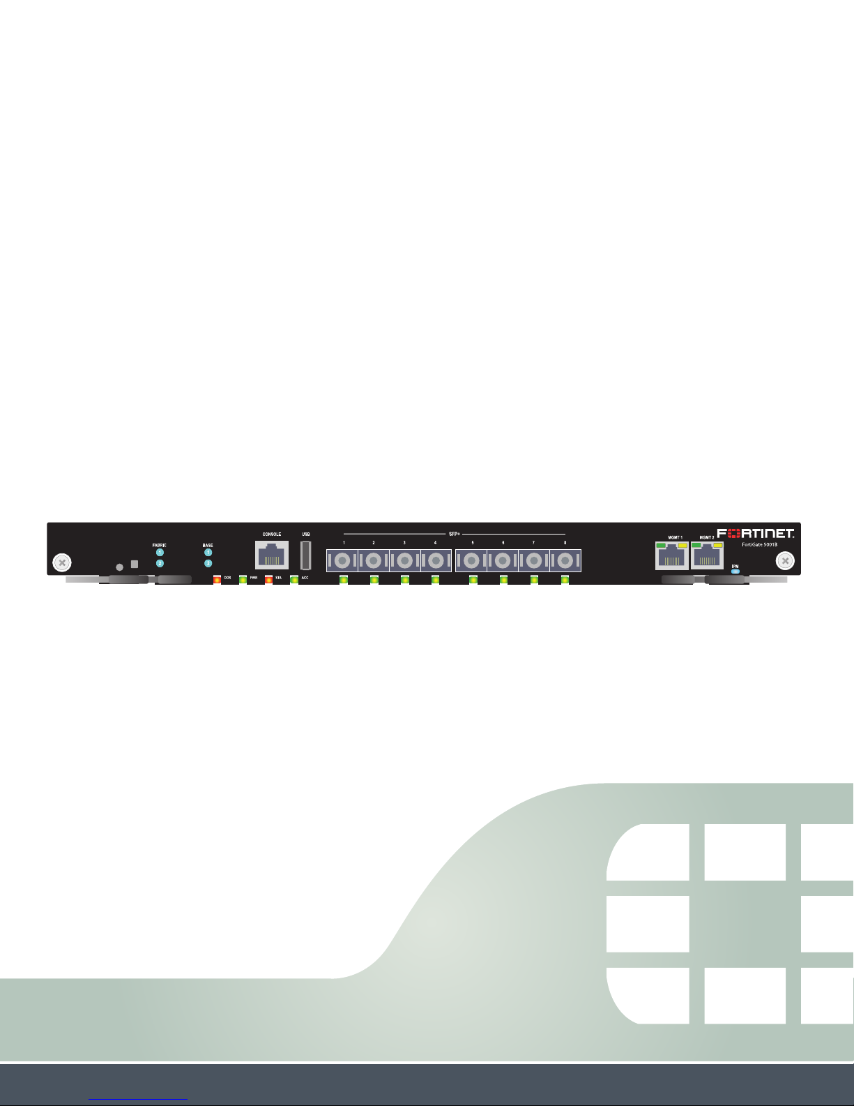
The FortiGate-5001B security system contains eight front panel 10-gigabit SFP+
interfaces, two base backplane 1-gigabit interfaces, and two fabric backplane 10-gigabit
interfaces. The front panel interfaces can also operate as 1-gigabit SFP interfaces. Use
the front panel interfaces for connections to your networks and the backplane interfaces
for communication across the ATCA chassis backplane. The FortiGate-5001B also
includes two front panel RJ45 10/100/1000 management Ethernet interfaces, one RJ45
front panel serial management port, and one front panel USB port.
Figure 1: FortiGate-5001B front panel
Factory Use
NMI Switch
Fabric and Base
network activity
LEDs
RJ-45
Console
USB
1 to 8
10 Gig
SFP+ Interfaces
IPM
LED
(board
position)
Retention
Screw
Extraction
Lever
FortiGate-5001B Security System Guide
01-400-134818-20120216 5
http://docs.fortinet.com/
OOS
LED
PWR
LED
STA
LED
ACC
LED
Retention
Screw
Extraction
Lever
MGMT 1 and MGMT 2
10/100/1000 Copper
Management Interfaces
Page 6
Physical description FortiGate-5001B security system
The FortiGate-5001B front panel 10-gigabit interfaces and fabric backplane interfaces
also provide NP4-accelerated network processing for eligible traffic passing through
these interfaces.
You can also configure two or more FortiGate-5001B boards to create a high availability
(HA) cluster using the base or fabric backplane interfaces for HA heartbeat
communication through the chassis backplane, leaving front panel interfaces available
for network connections.
In most cases the base backplane interfaces are used for HA heartbeat communication
and the fabric backplane interfaces are used for data communication.
The FortiGate-5001B board also supports high-end FortiGate features including 802.1Q
VLANs, multiple virtual domains, 802.3ad aggregate interfaces, and FortiOS Carrier.
The FortiGate-5001B board includes the following features:
• Eight front panel SFP+ 10-gigabit interfaces (port1 to port8) accelerated by two
FortiASIC NP4 network processors. Can also be configured as SFP 1-gigabit
interfaces.
• Two front panel 10/100/1000Base-T copper 1-gigabit management Ethernet
interfaces (mgmt1 and mgmt2). These interfaces are for management purposes only
and cannot forward traffic.
• Two base backplane 1-gigabit interfaces (base1 and base2) for HA heartbeat
communications across the FortiGate-5000 chassis base backplane.
• Two fabric backplane 10-gigabit interfaces (fabric1 and fabric2) for data
communications across the FortiGate-5000 chassis fabric backplane.
• Two NP4 network processors that provide firewall and IPsec VPN acceleration for the
port1 to port8 interfaces.
• Internal 64 GByte SSD for storing log messages, DLP archives, SQL log message
database, historic reports, IPS packet archiving, file quarantine, WAN Optimization
byte caching and web caching.
• One RJ-45 RS-232 serial console connection.
• 1 USB connector.
• NMI switch (for troubleshooting boards with part number P10633-01 and up, as
recommended by Fortinet Support).
• Mounting hardware.
• LED status indicators.
Physical description
Table 2: FortiGate-5001B board physical description
Dimensions
Weight 8.6 lb. (3.9 kg)
Operating Temperature 32 to 104°F (0 to 40°C)
Storage Temperature -13 to 158°F (-35 to 70°C)
Relative Humidity 5 to 90% (Non-condensing)
Power consumption Maximum: 225WDC; Average: 187 WDC
Max Current 4.69A
Heat Dissipation 768 BTU/h
6 01-400-134818-20120216
1.21 x 11.52 x 13.8 in. (3.1 x 29.3 x 35.1 cm) (Height x Width
x Depth)
FortiGate-5001B Security System Guide
http://docs.fortinet.com/
Page 7

FortiGate-5001B security system Front panel components
Front panel components
From the FortiGate-5001B front panel you can view the status of the front panel LEDs to
verify that the board is functioning normally. You also connect the FortiGate-5001B board
to your 10-gigabit network using the 1 to 8 front panel SFP+ or SFP connectors. The front
panel also includes two Ethernet management interfaces, an RJ-45 console port for
connecting to the FortiOS CLI and a USB port. The USB port can be used with any USB
key for backing up and restoring configuration files.
LEDs
Table 3: FortiGate-5001B LEDs
LED State Description
Off Fabric backplane interface 1 or 2 (fabric1 or fabric2) is
Fabric 1 and 2
Base 1 and 2
OOS
(Out of Service)
PWR (Power) Green The FortiGate-5001B board is powered on.
STA (Status)
ACC (Disk
activity)
1 to 8
Flashing
Green
Green Base backplane interface 1 or 2 (base1 or base2) is
Flashing
Green
Off Normal operation.
Amber A fault condition exists and the FortiGate-5001B blade
Off The FortiGate-5001B board is powered on.
Flashing
Green
Off or
Flashing
green
Green The correct cable is connected to the port1 to port8
Flashing
Green
Off No link is established.
connected at 10 Gbps.
Network activity at fabric backplane interface 1 or 2
(fabric1 or fabric2).
connected at 1 Gbps.
Network activity at base backplane interface 1 or 2
(base1 or base2).
is out of service (OOS). This LED may also flash very
briefly during normal startup.
The FortiGate-5001B is starting up. If this LED is
flashing at any time other than system startup, a fault
condition may exist.
The ACC LED flashes green when the FortiGate-5001B
board accesses the FortiOS flash disk. The FortiOS
flash disk stores the current FortiOS firmware build and
configuration files. The system accesses the flash disk
when starting up, during a firmware upgrade, or when
an administrator is using the CLI or GUI to change the
FortiOS configuration. Under normal operating
conditions this LED flashes occasionally, but is mostly
off.
interface and the connected equipment has power.
Network activity at the interface.
FortiGate-5001B Security System Guide
01-400-134818-20120216 7
http://docs.fortinet.com/
Page 8

Front panel components FortiGate-5001B security system
Table 3: FortiGate-5001B LEDs (Continued)
LED State Description
Link/Act
(Left
LED)
MGMT 1
and
MGMT 2
Speed
(Right
LED)
Solid
Green
Indicates the management interface (mgmt1 or mgmt2)
is connected with the correct cable and the attached
network device has power.
Blinking
Indicates network traffic on this interface.
Green
Off No Link
Green Connection at 1 Gbps.
Amber Connection at 100 Mbps.
Off Connection at 10 Mbps.
Blue The FortiGate-5001B board is ready to be hot-swapped
(removed from the chassis). If the IPM light is blue and
no other LEDs are lit the FortiGate-5001B board has lost
power
IPM
Flashing
Blue
The FortiGate-5001B board is changing from hot swap
to running mode or from running mode to hot swap. This
happens when the FortiGate-5001B board is starting up
or shutting down.
Off Normal operation. The FortiGate-5001B board is in
contact with the chassis backplane.
Connectors
Table 4: FortiGate-5001B connectors
Connector Type Speed Protocol Description
CONSOLE
RJ-45 9600 bps
8/N/1
RS-232
serial
Serial connection to the command
line interface.
SFP+ 10-gigabit/auto Ethernet 10-Gigabit SFP+ connection to
1 to 8
10-Gigabit networks (port1 to
port8). Small form-factor pluggable
transceiver.
SFP 1-gigabit/auto Ethernet 1-Gigabit SFP+ connection to
1 to 8
1-Gigabit networks (port1 to
port8). Small form-factor pluggable
transceiver.
MGMT 1
and MGMT
2
USB
RJ-45 10/100/1000
Base-T
USB USB key for firmware updates and
Ethernet Copper 1-gigabit connection to
10/100/1000Base-T copper
networks for management or
system administration.
configuration backup.
8 01-400-134818-20120216
FortiGate-5001B Security System Guide
http://docs.fortinet.com/
Page 9

FortiGate-5001B security system Base backplane communication
NMI switch
When working with Fortinet Support to troubleshoot problems with FortiGate-5001B
boards with part number P10633-01 and up you can use the front panel non-maskable
interrupt (NMI) switch to assist with troubleshooting. Pressing this switch causes the
software to dump registers/backtraces to the console. After the data is dumped the
board reboots. While the board is rebooting, traffic is temporarily blocked. The board
should restart normally and traffic can resume once its up and running.
Base backplane communication
The FortiGate-5001B base backplane 1-gigabit interfaces (base1 and base2) are typically
used for HA heartbeat or other management communication between FortiGate-5001B
boards installed in the same or in different FortiGate-5000 series chassis. You can also
configure FortiGate-5001B boards to use the base backplane interfaces for data
communication between FortiGate boards. To support base backplane communications
your FortiGate-series chassis must include one or more FortiSwitch-5000 series or other
1-gigabit base backplane switches installed in the chassis in base slots 1 and 2.
For information about base backplane communication in FortiGate-5000 series chassis,
see the FortiSwitch Backplane Communication Guide. For information about
FortiSwitch-5000 series boards, see the FortiSwitch-5000 Series documents on the
FortiSwitch page of the Fortinet Technical Documentation website.
Fabric backplane communication
The FortiGate-5001B fabric backplane interfaces (fabric1 and fabric2) are typically used
for data communication between FortiGate-5001B boards installed in the same or in
different FortiGate-5000 series chassis. To support 10-gigabit fabric backplane
communications your FortiGate-5000 series chassis must include one or more
FortiSwitch-5003A or FortiSwitch-5003B boards or other 10-gigabit fabric backplane
switching boards installed in the chassis in fabric slots 1 and 2.
For information about base backplane communication in FortiGate-5000 series chassis,
see the FortiSwitch Backplane Communication Guide. For information about
FortiSwitch-5000 series boards, see the FortiSwitch-5000 Series documents on the
FortiSwitch page of the Fortinet Technical Documentation website.
Accelerated packet forwarding and policy enforcement (NP4
network processors)
The FortiGate-5001B board includes two NP4 processors that provide accelerated
packet forwarding and policy enforcement for all FortiGate-5001B front panel and
backplane interfaces. Accelerated packet forwarding and policy enforcement results in
accelerated small packet performance required for voice, video, and other multimedia
streaming applications.
The following traffic scenarios are recommended for the accelerated interfaces:
• Small packet applications, such as voice over IP (VoIP).
The FortiGate-5001B accelerated interfaces provide wire speed performance for small
packet applications.
FortiGate-5001B Security System Guide
01-400-134818-20120216 9
http://docs.fortinet.com/
Page 10
Accelerated packet forwarding and policy enforcement (NP4 network processors) FortiGate-5001B security system
• Latency sensitive applications, such as multimedia.
The FortiGate-5001B accelerated interfaces add much less latency than normal (nonaccelerated) interfaces.
• Session Oriented Traffic with long session lifetime, such as FTP sessions.
Packet size does not affect performance for traffic with long session lifetime. For long
sessions, processing that would otherwise be handled by the FortiGate-5001B CPUs
is off-loaded to the acceleration module.
• Firewall, intrusion protection (IPS), and antivirus, when there is a reasonable
percentage of P2P packets.
• Firewall and IPsec VPN applications.
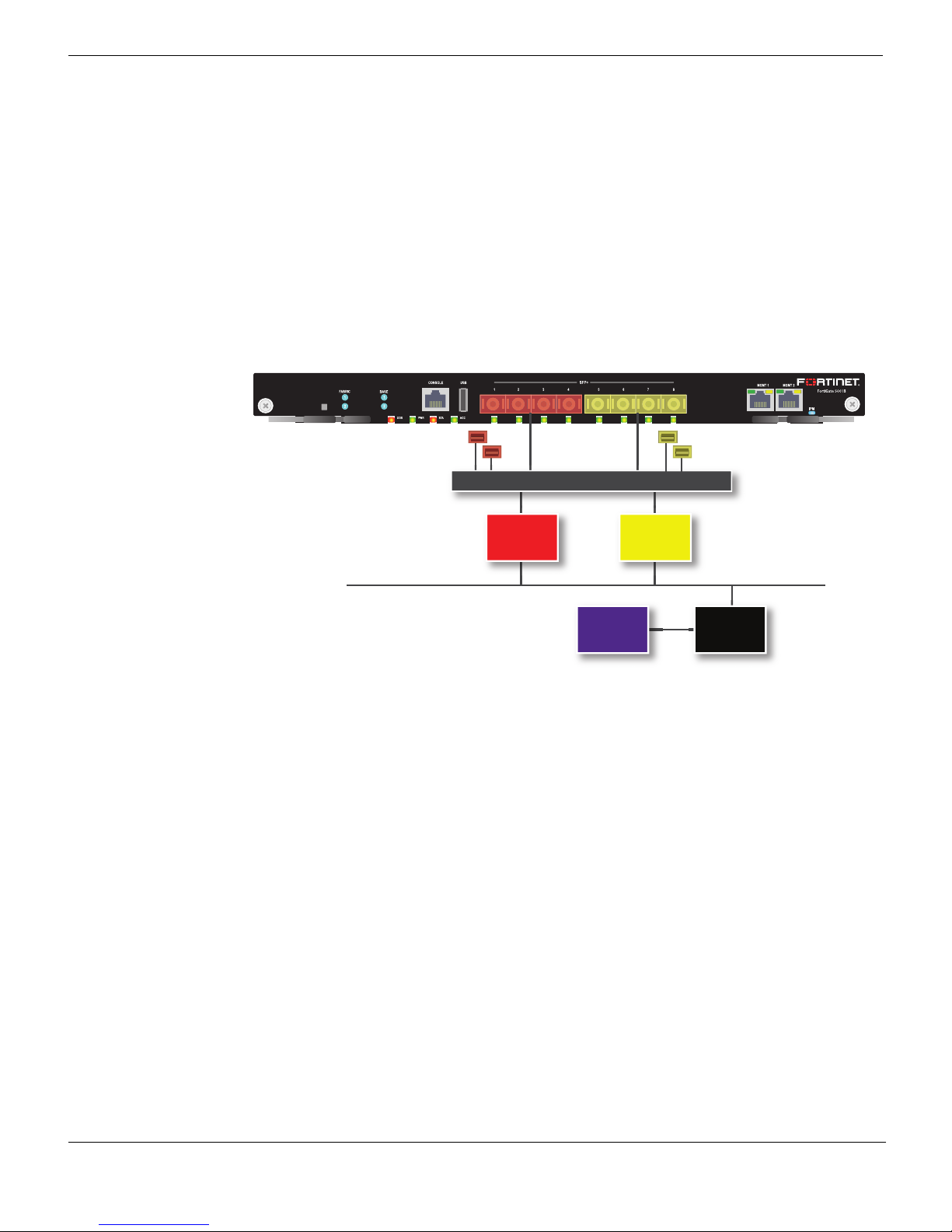
Figure 2: FortiGate-5001B NP4 to interface mapping
fabric1
base1
fabric2
base2
Ethernet Switch
FortiASIC
NP4
FortiASIC
NP4
System Bus
CPUCP7
Traffic between interfaces that use the same NP4 processor experiences the highest
acceleration.
• The port1, port2, port3, port4, fabric1 and base1 interfaces are connected to one NP4
processor.
• The port5, port6, port7, port8, fabric2 and base2 interfaces are connected to the other
NP4 processor.
For example, for maximum NP4 acceleration of traffic received on port1 the traffic must
exit the FortiGate-5001B board on port2, port3, port4, or fabric1. Also, for maximum
acceleration of traffic received on port5 the traffic must exit the FortiGate-5001B board
on port6, port7, port8, or fabric2.
10 01-400-134818-20120216
FortiGate-5001B Security System Guide
http://docs.fortinet.com/
Page 11

FortiGate-5001B
Hardware installation
Before use, the FortiGate-5001B board must be correctly inserted into an Advanced
Telecommunications Computing Architecture (ATCA) chassis that can provide sufficient
power and cooling (for example, the FortiGate-5060 chassis or the NEBS-compliant
FortiGate-5140-R chassis).
This section describes:
• Installing SFP+ transceivers
• Changing FortiGate-5001B SW2 switch settings
• FortiGate-5001B mounting components
• Inserting a FortiGate-5001B board
• Shutting down and removing a FortiGate-5001B board
• Power cycling a FortiGate-5001B board
• Installing SFP+ transceivers
• Troubleshooting
Installing SFP+ transceivers
The FortiGate-5001B board ships with two SR SFP+ transceivers that you must install for
normal operation of the FortiGate-5001B front panel interfaces (port1 to port8). Since the
board is shipped with 2 SPT+ interfaces, if you want to connect more than 2 front panel
interfaces you should purchase and install additional compatible SFP+ transceivers for
these interfaces. You can also configure front panel interfaces to operated at 1-gigabit
and install SFP transceivers.
The SFP transceivers are inserted into cage sockets numbered 1 to 8 on the
FortiGate-5001B front panel. You can install the SFP transceivers before or after inserting
the FortiGate-5001B board into a FortiGate-5000 series or other ATCA chassis.
You can install the following types of SFP transceivers for connectors 1 to 8:
• SFP+ SR (10 gigabits)
• SFP+ LR (10 gigabits)
• SFP (1gigabit)
To install SFP+ transceivers
To complete this procedure, you need:
• A FortiGate-5001B board
• Two or more SFP+ or SFP transceivers
• An electrostatic discharge (ESD) preventive wrist or ankle strap with connection cord
FortiGate-5001B boards must be protected from static discharge and physical shock.
Only handle or work with FortiGate-5001B boards at a static-free workstation. Always
wear a grounded electrostatic discharge (ESD) preventive wrist strap when handling
FortiGate-5001B boards.
FortiGate-5001B Security System Guide
01-400-134818-20120216 11
http://docs.fortinet.com/
Page 12

Changing FortiGate-5001B SW2 switch settings Hardware installation
1 Attach the ESD wrist strap to your wrist and to an available ESD socket or wrist strap
terminal.
2 Remove the caps from SFP+ or SFP cage sockets on the FortiGate-5001B front
panel.
Handling the SFP+ and SFP transceivers by holding the release latch can damage the
connector. Do not force the SFP+ or SFP transceivers into the cage slots. If the
transceiver does not easily slide in and click into place, it may not be aligned correctly. If
this happens, remove the SFP+ or SFP transceiver, realign it and slide it in again.
3 Hold the sides of the SFP+ or SFP transceiver and slide the transceiver into the cage
socket until it clicks into place.
Changing FortiGate-5001B SW2 switch settings
You should only change the SW2 switch setting if are required to install the
FortiGate-5001B board in a chassis that does not contain a functioning shelf manager.
The default SW2 setting is required for most uses of the FortiGate-5001B including
ELBCv3.
The SW2 switch on the FortiGate-5001B board is factory set by Fortinet to detect a shelf
manager (Figure 3). This is the correct setting if you are installing the FortiGate-5001B
board in a chassis that contains an operating shelf manager (such as a FortiGate-5000
series chassis).
The top of the FortiGate-5001B board is covered with a metal panel. The printed circuit
board is under the metal panel. SW2 is located on the printed circuit board and is
accessible through the small opening the metal panel as shown in Figure 3.
Figure 3: Location of SW2 on the FortiGate-5001B board
SW2
3421
ON
FortiGate-5001B
Front Faceplate
SW2
Factory Default
3421
(Requires Shelf
Manager)
ON
SW2
Standalone Mode
3421
(No Shelf Manager)
ON
Location of SW2
12 01-400-134818-20120216
FortiGate-5001B Security System Guide
http://docs.fortinet.com/
Page 13

Hardware installation Changing FortiGate-5001B SW2 switch settings
Figure 4: Factory default shelf manager mode setting for SW2
SW2
Factory Default
3421
(Requires Shelf
ON
By default a FortiGate-5001B board will not start up if the board is installed in a chassis
that does not contain a shelf manager or that contains a shelf manager that is not
operating. Before installing a FortiGate-5001B in a chassis that does not contain an
operating shelf manager you must change the SW2 switch setting to that shown in
Figure 5.
Figure 5: Standalone mode setting for SW2
SW2
ON
Manager)
Standalone Mode
3421
(No Shelf Manager)
In all cases you should confirm that you have the correct SW2 setting before installing the
board in a chassis.
Table 5: FortiGate-5001B SW2 settings
Correct
Chassis
FortiGate-5140B or 5060 or a
ATCA chassis with a compatible
operating shelf manager (factory
default shelf manager mode).
SW2
Setting
SW2
Result of wrong jumper setting
Shelf manager cannot find
FortiGate-5001B board. No shelf
manager information about the
3421
FortiGate-5001B board available.
ON
Any ATCA chassis without an
operating shelf manager
(standalone mode).
SW2
FortiGate-5001B board will not start
up.
3421
ON
If the shelf manager in a FortiGate-5000 series chassis is missing or not functioning,
FortiGate-5001B boards with factory default SW2 settings will not start up.
To change or verify the SW2 switch setting
To complete this procedure, you need:
• A FortiGate-5001B board
• A tool for changing the SW2 switch setting (optional)
FortiGate-5001B Security System Guide
01-400-134818-20120216 13
http://docs.fortinet.com/
Page 14

FortiGate-5001B mounting components Hardware installation
• An electrostatic discharge (ESD) preventive wrist strap with connection cord
FortiGate-5001B boards must be protected from static discharge and physical shock.
Only handle or work with FortiGate-5001B boards at a static-free workstation. Always
wear a grounded electrostatic discharge (ESD) preventive wrist strap when handling
FortiGate-5001B boards.
1 Attach the ESD wrist strap to your wrist and to an available ESD socket or wrist strap
terminal.
2 If you have installed the FortiGate-5001B board in a chassis, remove it.
For removal instructions, see “Shutting down and removing a FortiGate-5001B board”
on page 17.
3 Use Figure 3 on page 12 to locate SW2 on the FortiGate-5001B board.
4 If required, change SW2 to the correct setting.
5 Insert the FortiGate-5001B board into a chassis and verify that the board starts up
and operates correctly.
For inserting instructions, see “Inserting a FortiGate-5001B board” on page 15.
FortiGate-5001B mounting components
To install a FortiGate-5001B board you slide the board into an open slot in the front of an
ATCA chassis and then use the mounting components to lock the board into place in the
slot. When locked into place and positioned correctly the board front panel is flush with
the chassis front panel. The board is also connected to the chassis backplane.
FortiGate-5001B boards are horizontal when inserted into a FortiGate-5060 chassis and
vertical when inserted into a FortiGate-5140 chassis. The inserting and removing
procedures are the same in either case. For clarity the descriptions in this document
refer to the left (top) and right (bottom) mounting components.
To position the board correctly you must use the mounting components shown in
Figure 6 for the right (bottom) side of the front panel. The mounting components on the
left (top) side of the FortiGate-5001B front panel are the same but reversed. The
FortiGate-5001B mounting components align the board in the chassis slot and are used
to insert and eject the board from the slot.
14 01-400-134818-20120216
FortiGate-5001B Security System Guide
http://docs.fortinet.com/
Page 15

Hardware installation Inserting a FortiGate-5001B board
Figure 6: FortiGate-5001B right (bottom) mounting components
Closed
Alignment Pin
Retention
Screw
Handle
Lock
Handle
Alignment
Pin
Retention
Screw
Lock
Open
Alignment Pin
Alignment
Pin
Retention
Hook
Lock
Retention
Handle
Handle
Screw
Hook
Screw
Lock
The FortiGate-5001B handles align the board in the chassis slot and are used to insert
and eject the board from the slot. The right (bottom) handle activates a microswitch that
turns on or turns off power to the board. When the right (bottom) handle is open the
microswitch is off and the board cannot receive power. When the right (bottom) handle is
fully closed the microswitch is on and if the board is fully inserted into a chassis slot the
board can receive power.
You can use front panel reset switch to cycle the power and reset the board without
removing the board from the chassis. See “Power cycling a FortiGate-5001B board” on
page 19.
Inserting a FortiGate-5001B board
The FortiGate-5001B board must be fully installed in a chassis slot, with the handles
closed and locked and retention screws fully tightened for the FortiGate-5001B board to
receive power and operate normally. If the FortiGate-5001B board is not receiving power,
the IPM LED glows solid blue and all other LEDs remain off. See “Front panel
components” on page 7.
It is important to carefully seat the FortiGate-5001B board all the way into the chassis, to
avoid using excessive force on the handles, and to make sure that the handles are
properly locked. Only then will the FortiGate-5001B board power-on and start up
correctly.
FortiGate-5001B boards are hot swappable. The procedure for inserting
a FortiGate-5001B board into a chassis slot is the same whether or not the chassis is
powered on.
FortiGate-5001B Security System Guide
01-400-134818-20120216 15
http://docs.fortinet.com/
Page 16

Inserting a FortiGate-5001B board Hardware installation
To insert a FortiGate-5001B board into a chassis slot
Do not carry the FortiGate-5001B board by holding the handles or retention screws.
When inserting or removing the FortiGate-5001B board from a chassis slot, handle the
board by the front panel. The handles are not designed for carrying the board. If the
handles become bent or damaged the FortiGate-5001B board may not align correctly in
the chassis slot.
To complete this procedure, you need:
• A FortiGate-5001B board
• An ATCA chassis with an empty slot
• An electrostatic discharge (ESD) preventive wrist strap with connection cord
FortiGate-5001B boards must be protected from static discharge and physical shock.
Only handle or work with FortiGate-5001B boards at a static-free workstation. Always
wear a grounded electrostatic discharge (ESD) preventive wrist strap when handling
FortiGate-5001B boards.
1 Attach the ESD wrist strap to your wrist and to an available ESD socket or wrist strap
terminal.
2 If required, remove the protective metal frame that the FortiGate-5001B board has
been shipped in.
3 Insert the FortiGate-5001B board into the empty slot in the chassis.
4 Unlock the handles by squeezing the handle locks.
5 Open the handles to their fully open positions.
To avoid damaging the lock, make sure you squeeze the handles fully to unlock them
before opening. The handles should pop easily out of the board front panel.
Alignment Pin
Alignment Pin
Handle
Open
Handle
Lock
6 Carefully guide the board into the chassis using the rails in the slot.
Insert the board by applying moderate force to the front faceplate (not the handles) to
slide the board into the slot. The board should glide smoothly into the chassis slot. If
you encounter any resistance while sliding the board in, the board could be aligned
incorrectly. Pull the board back out and try inserting it again.
7 Slide the board in until the alignment pins are inserted half way into their sockets in
the chassis.
16 01-400-134818-20120216
FortiGate-5001B Security System Guide
http://docs.fortinet.com/
Page 17

Hardware installation Shutting down and removing a FortiGate-5001B board
8 Turn both handles to their fully-closed positions.
The handles should hook into the sides of the chassis slot. Closing the handles draws
the FortiGate-5001B board into place in the chassis slot and into full contact with the
chassis backplane. The FortiGate-5001B front panel should be in contact with the
chassis front panel and both handles should lock into place.
As the handles closed power is supplied to the board. If the chassis is powered on the
IPM LED starts flashing blue. If the board is aligned correctly, inserted all the way into
the slot, and the handles are properly closed the IPM LED flashes blue for a few
seconds. At the same time the STATUS LED flashes green, the interface LEDs flash
amber, and the ACC LED starts flashing green. After a few seconds the IPM LED goes
out and the FortiGate-5001B firmware starts up. During start up the STATUS LED may
continue to flash green. Once the board has started up and is operating correctly, the
front panel LEDs are lit as described in Table 6.
Table 6: FortiGate-5001B normal operating LEDs
LED State
OOS Off
PWR Green
STA Off
ACC
Off (Or flashing green when the system accesses the
FortiGate-5001B flash disk.)
IPM Off
If the board has not been inserted properly the IPM LED changes to solid blue and all
other LEDS turn off. If this occurs, open the handles, slide the board part way out, and
repeat the insertion process.
9 Once the board is inserted correctly, fully tighten the retention screws to lock the
FortiGate-5001B board into position in the chassis slot.
Retention
Screw
Tighten
Shutting down and removing a FortiGate-5001B board
The following procedure describes how to correctly use the FortiGate-5001B mounting
components described in “FortiGate-5001B mounting components” on page 14 to
remove a FortiGate-5001B board from an ATCA chassis slot.
To avoid potential hardware problems, always shut down the FortiGate-5001B operating
system (FortiOS) properly before power cycling the FortiGate-5001B board.
FortiGate-5001B Security System Guide
01-400-134818-20120216 17
http://docs.fortinet.com/
Page 18

Shutting down and removing a FortiGate-5001B board Hardware installation
FortiGate-5001B boards are hot swappable. The procedure for removing
a FortiGate-5001B board from a chassis slot is the same whether or not the chassis is
powered on.
To remove a FortiGate-5001B board from a chassis slot
Do not carry the FortiGate-5001B board by holding the handles or retention screws.
When inserting or removing the FortiGate-5001B board from a chassis slot, handle the
board by the front panel. The handles are not designed for carrying the board. If the
handles become bent or damaged the FortiGate-5001B board may not align correctly in
the chassis slot.
To complete this procedure, you need:
• An ATCA chassis with a FortiGate-5001B board installed
• An electrostatic discharge (ESD) preventive wrist strap with connection cord
FortiGate-5001B boards must be protected from static discharge and physical shock.
Only handle or work with FortiGate-5001B boards at a static-free workstation. Always
wear a grounded electrostatic discharge (ESD) preventive wrist strap when handling
FortiGate-5001B boards.
1 Shut down the operating system running on the FortiGate-5001B board. For example:
• From the web-based manager, go to System > Status and from the Unit Operation
widget, select Shutdown and then select OK.
• From the CLI enter
execute shutdown
2 Attach the ESD wrist strap to your wrist and to an available ESD socket or wrist strap
terminal.
3 Disconnect all cables from the FortiGate-5001B board, including all network cables,
the console cable, and any USB cables or keys.
4 Fully loosen the retention screws on the FortiGate-5001B front panel.
5 Unlock the handles by squeezing the handle locks.
6 Slowly open both handles a small amount (about 8 degrees) until the IPM LED flashes
blue.
7 Keep the handles in this position until the IPM LED stops flashing and becomes solid
blue.
Waiting for the IPM LED to change to solid blue makes sure that the board software
shutdowns completely before disconnecting it from backplane power.
18 01-400-134818-20120216
Retention
Screw
Loosen
FortiGate-5001B Security System Guide
http://docs.fortinet.com/
Page 19

Hardware installation Power cycling a FortiGate-5001B board
8 Open the handles to their fully open positions.
To avoid damaging the lock, make sure you squeeze the handles fully to unlock them
before opening. The handles should pop easily out of the board front panel.
You need to open the handles with moderate pressure to eject the board from the
chassis. Pivoting the handles turns off the microswitch, turns off all LEDs, and ejects
the board from the chassis slot.
Alignment Pin
Alignment Pin
Handle
Open
Handle
Lock
9 Pull the board about half way out.
10 Turn both handles to their fully-closed positions.
Alignment Pin
Close
Handle
11 Carefully slide the board completely out of the slot.
12 Re-attach the protective metal frame before shipping or storing the FortiGate-5001B
board.
Power cycling a FortiGate-5001B board
This section describes how to cycle the power on a FortiGate-5001B board by opening
the right handle (the lower handle when the board is installed vertically in a
FortiGate-5140 chassis) to activate a switch that cycles the power without removing the
board from the chassis. The steps recommend loosening the retention screws before
opening the handle to allow the handle to toggle the switch. During this process the
board may move out a small amount (less than 1 mm).
To avoid potential hardware problems, always shut down the FortiGate-5001B operating
system properly before power cycling the FortiGate-5001B board.
Fully Closed
and Locked
Alignment Pin
Handle
To power cycle a FortiGate-5001B board without fully removing the board from the
chassis
To complete this procedure, you need:
FortiGate-5001B Security System Guide
01-400-134818-20120216 19
http://docs.fortinet.com/
Page 20

Troubleshooting Hardware installation
• An ATCA chassis with a FortiGate-5001B board installed
• An electrostatic discharge (ESD) preventive wrist strap with connection cord
FortiGate-5001B boards must be protected from static discharge and physical shock.
Only handle or work with FortiGate-5001B boards at a static-free workstation. Always
wear a grounded electrostatic discharge (ESD) preventive wrist strap when handling
FortiGate-5001B boards.
1 Shut down the operating system running on the FortiGate-5001B board. For example:
• From the web-based manager, go to the Unit Operation dashboard widget, select
Shutdown and then select OK.
• From the CLI enter
execute shutdown
2 Attach the ESD wrist strap to your wrist and to an available ESD socket or wrist strap
terminal.
3 Fully loosen the retention screws on the FortiGate-5001B front panel.
4 Unlock both handles by squeezing the handle locks.
5 Slowly open both handles a small amount (about 8 degrees) until the IPM LED flashes
6 Keep the handles in this position until the IPM LED stops flashing and becomes solid
7 After 10 seconds snap both handles back into place.
8 Fully tighten the retention screws to lock the FortiGate-5001B board into position in
Troubleshooting
This section describes some common troubleshooting topics.
FortiGate-5001B board does not start up
Shelf manager or firmware problems may prevent a FortiGate-5001B board from starting
up correctly.
Chassis with a shelf manager: no communication with shelf manager
If the FortiGate-5001B board is receiving power and the handles are fully closed and the
FortiGate-5001B still does not start up, the problem could be that the FortiGate-5001B
cannot communicate with the chassis shelf manager. This problem can only occur in an
ATCA chassis that contains a shelf manager.
Unlock
Handle
blue.
blue.
The board powers up, the LEDs light and in a few minutes the FortiGate-5001B board
operates normally.
the chassis slot.
20 01-400-134818-20120216
FortiGate-5001B Security System Guide
http://docs.fortinet.com/
Page 21

Hardware installation Troubleshooting
To correct this problem power down and then restart the chassis. If you are operating a
FortiGate-5000 series chassis you can power down and then restart the chassis without
removing FortiGate-5000 series components.
All chassis: Firmware problem
If the FortiGate-5001B board is receiving power and the handles are fully closed, and you
have restarted the chassis and the FortiGate-5001B still does not start up, the problem
could be with FortiOS. Connect to the FortiGate-5001B console and try cycling the
power to the board. If the BIOS starts up, interrupt the BIOS startup and install a new
firmware image. If this does not solve the problem, contact Fortinet Customer Service
and Support.
FortiGate-5001B STA (status) LED is flashing during system operation
Normally, the FortiGate-5001B STA (status) LED is off when the FortiGate-5001B board is
operating normally. If this LED starts flashing while the board is operating, a fault
condition may exist. At the same time the FortiGate-5001B may stop processing traffic.
To resolve the problem you can try removing and reinserting the FortiGate-5001B board
in the chassis slot. Reloading the firmware may also help.
If this does not solve the problem there may have been a hardware failure or other
problem. Contact Fortinet Technical Support for assistance.
FortiGate-5001B Security System Guide
01-400-134818-20120216 21
http://docs.fortinet.com/
Page 22

Troubleshooting Hardware installation
22 01-400-134818-20120216
FortiGate-5001B Security System Guide
http://docs.fortinet.com/
Page 23

FortiGate-5001B
Quick Configuration Guide
This section is a quick start guide to connecting and configuring a FortiGate-5001B
security system for your network.
Before using this chapter, your FortiGate-5000 series or compatible ATCA chassis should
be mounted and connected to your power system. In addition, your FortiGate-5001B
board should be inserted into the chassis and SFP+ transceivers should be installed. The
FortiGate-5001B board should also be powered up and the front panel LEDs should
indicate that the board is functioning normally.
This chapter includes the following topics:
• Registering your Fortinet product
• Planning the configuration
• Choosing the configuration tool
• Factory default settings
• Configuring NAT/Route mode
• Configuring Transparent mode
• Upgrading FortiGate-5001B firmware
• FortiGate-5001B base backplane data communication
Registering your Fortinet product
Register your Fortinet product to receive Fortinet customer services such as product
updates and customer support. You must also register your product for FortiGuard
services such as FortiGuard Antivirus and Intrusion Prevention updates and for
FortiGuard Web Filtering and AntiSpam.
Register your product by visiting https://support.fortinet.com and selecting
Register/Renew.
To register, enter your contact information and the serial numbers of the Fortinet products
that you or your organization have purchased. You can register multiple Fortinet products
in a single session without re-entering your contact information.
Planning the configuration
Before beginning to configure your FortiGate-5001B security system, you need to plan
how to integrate the system into your network. Your configuration plan depends on the
operating mode that you select: NAT/Route mode (the default) or Transparent mode.
NAT/Route mode
In NAT/Route mode, the FortiGate-5001B security system is visible to the networks that it
is connected to. Each interface connected to a network must be configured with an IP
address that is valid for that network. In many configurations, in NAT/Route mode all of
the FortiGate interfaces are on different networks, and each network is on a separate
subnet.
FortiGate-5001B Security System Guide
01-400-134818-20120216 23
http://docs.fortinet.com/
Page 24

Planning the configuration Quick Configuration Guide
You would typically use NAT/Route mode when the FortiGate-5001B security system is
deployed as a gateway between private and public networks. In the default NAT/Route
mode configuration, the FortiGate-5001B security system functions as a firewall. Firewall
policies control communications through the FortiGate-5001B security system. No traffic
can pass through the FortiGate-5001B security system until you add firewall policies.
In NAT/Route mode, firewall policies can operate in NAT mode or in Route mode. In NAT
mode, the FortiGate firewall performs network address translation before IP packets are
sent to the destination network. In Route mode, no translation takes place.
Figure 7: Example FortiGate-5001B board operating in NAT/Route mode
Internal
network
Transparent mode
In Transparent mode, the FortiGate-5001B security system is invisible to the network. All
of the FortiGate-5001B interfaces are connected to different segments of the same
network. In Transparent mode you only have to configure a management IP address so
that you can connect to the FortiGate-5001B security system to make configuration
changes and so the FortiGate-5001B security system can connect to external services
such as the FortiGuard Distribution Network (FDN).
You would typically deploy a FortiGate-5001B security system in Transparent mode on a
private network behind an existing firewall or behind a router. In the default Transparent
mode configuration, the FortiGate-5001B security system functions as a firewall. No
traffic can pass through the FortiGate-5001B security system until you add firewall
policies.
port1
192.168.1.2
port2
204.23.1.2
FortiGate-5001B
board in NAT/Route
mode
NAT mode policies
controlling trafc
between internal
and extermal networks
24 01-400-134818-20120216
FortiGate-5001B Security System Guide
http://docs.fortinet.com/
Page 25

Quick Configuration Guide Choosing the configuration tool
Figure 8: Example FortiGate-5001B board operating in Transparent mode
Internal
network
Management
IP 192.168.1.99
port1
Transparent mode policies
controlling trafc
between internal
and extermal networks
FortiGate-5001B
board in
Transparent mode
Choosing the configuration tool
You can use either the web-based manager or the Command Line Interface (CLI) to
configure the FortiGate board.
Web-based manager
The FortiGate-5001B web-based manager is an easy to use management tool. Use the
web-based manager to configure the FortiGate-5001B administrator password, the
interface addresses, the default gateway, and the DNS server addresses.
Requirements:
• An Ethernet connection between the FortiGate-5001B board and management
computer.
• Internet Explorer 6.0 or higher on the management computer.
port2
192.168.1.1
Gateway to
public network
204.23.1.2
Command Line Interface (CLI)
The CLI is a full-featured management tool. Use it to configure the administrator
password, the interface addresses, the default gateway, and the DNS server addresses.
Requirements:
• The serial connector that came packaged with your FortiGate-5001B board.
• Terminal emulation application (for example, HyperTerminal for Windows) on the
management computer.
FortiGate-5001B Security System Guide
01-400-134818-20120216 25
http://docs.fortinet.com/
Page 26

Factory default settings Quick Configuration Guide
Factory default settings
The FortiGate-5001B unit ships with a factory default configuration. The default
configuration allows you to connect to and use the FortiGate-5001B web-based manager
to configure the FortiGate-5001B board onto the network. To configure the
FortiGate-5001B board onto the network you add an administrator password, change the
network interface IP addresses, add DNS server IP addresses, and, if required, configure
basic routing.
Table 7: FortiGate-5001B factory default settings
Operation Mode NAT/Route
Administrator Account
mgmt1 IP/Netmask 192.168.1.99/24
mgmt2 IP/Netmask 192.168.100.99/24
Default route
Primary DNS Server: 208.91.112.53
Secondary DNS Server: 208.91.112.52
User Name: admin
Password: (none)
Gateway: 192.168.100.1
Device: mgmt2
At any time during the configuration process, if you run into problems, you can reset the
FortiGate-5001B board to the factory defaults and start over. From the CLI enter
execute factory reset.
Configuring NAT/Route mode
Use Table 8 to gather the information you need to customize NAT/Route mode settings
for the FortiGate-5001B security system. You can use one table for each board to
configure.
Table 8: FortiGate-5001B board NAT/Route mode settings
Admin Administrator Password:
mgmt1
port1
port2
Default Route
DNS Servers
IP: _____._____._____._____
Netmask: _____._____._____._____
IP: _____._____._____._____
Netmask: _____._____._____._____
IP: _____._____._____._____
Netmask: _____._____._____._____
Device (Name of the Interface
connected to the external
network):
Default Gateway IP address: _____._____._____._____
The default route consists of the name of the interface connected
to an external network (usually the Internet) and the default gateway
IP address. The default route directs all non-local traffic to this
interface and to the external network.
Primary DNS Server: _____._____._____._____
Secondary DNS Server: _____._____._____._____
26 01-400-134818-20120216
FortiGate-5001B Security System Guide
http://docs.fortinet.com/
Page 27

Quick Configuration Guide Configuring NAT/Route mode
Using the web-based manager to configure NAT/Route mode
1 Connect port1 of the FortiGate-5001B board to the same hub or switch as the
computer you will use to configure the FortiGate-5001B board.
If you cannot connect to port1, see “Using the CLI to configure NAT/Route mode” on
page 28.
2 Configure the management computer to be on the same subnet as the port1 interface
of the FortiGate-5001B board. To do this, change the IP address of the management
computer to 192.168.1.2 and the netmask to 255.255.255.0.
3 To access the FortiGate-5001B web-based manager, start Internet Explorer and
browse to https://192.168.1.99 (remember to include the “s” in https://).
4 Type admin in the Name field and select Login.
To change the admin administrator password
1 Go to System > Admin > Administrators.
2 Select Change Password for the admin administrator and enter a new password.
See the Fortinet Knowledge Base article Recovering lost administrator account
passwords if you forget or lose an administrator account password and cannot log into
your FortiGate-5001B unit.
To configure interfaces
1 Go to System > Network > Interface and edit each interface to configure.
2 Set the addressing mode for the interface. (See the online help for information.)
• For manual addressing, enter the IP address and netmask for the interface that you
added to Table 8 on page 26.
• For DHCP addressing, select DHCP and any required settings.
• For PPPoE addressing, select PPPoE and enter the username and password and
any other required settings.
To configure the Primary and Secondary DNS server IP addresses
1 Go to System > Network > DNS.
2 Enter the Primary and Secondary DNS IP addresses that you added to Table 8 on
page 26 as required and select Apply.
To configure the Default Gateway
1 Go to Router > Static > Static Route and Edit the static route.
2 Select the Device that you recorded above.
3 Set Gateway to the Default Gateway IP address that you added to Table 8 on page 26.
4 Select OK.
FortiGate-5001B Security System Guide
01-400-134818-20120216 27
http://docs.fortinet.com/
Page 28

Configuring NAT/Route mode Quick Configuration Guide
Using the CLI to configure NAT/Route mode
1 Use the serial cable supplied with your FortiGate-5001B board to connect the
FortiGate-5001B Console port to the management computer serial port.
2 Start a terminal emulation program (HyperTerminal) on the management computer.
Use these settings:
Baud Rate (bps) 9600, Data bits 8, Parity None, Stop bits 1, and Flow Control None.
3 At the Login: prompt, type admin and press Enter twice (no password required).
4 Change the administrator password.
config system admin
edit admin
set password <password>
end
See the Fortinet Knowledge Base article Recovering lost administrator account
passwords if you forget or lose an administrator account password and cannot log into
your FortiGate-5001B unit.
5 Configure the mgmt1, port1, and port1 interfaces to the settings that you added to
Table 8 on page 26.
config system interface
edit mgmt1
set ip <intf_ip>/<netmask_ip>
next
edit port1
set ip <intf_ip>/<netmask_ip>
next
edit port2
set ip <intf_ip>/<netmask_ip>
end
6 Configure the primary and secondary DNS server IP addresses to the settings that
you added to Table 8 on page 26.
config system dns
set primary <dns-server_ip>
set secondary <dns-server_ip>
end
7 Configure the default gateway to the setting that you added to Table 8 on page 26.
config router static
edit 1
set device <interface_name>
set gateway <gateway_ip>
end
28 01-400-134818-20120216
FortiGate-5001B Security System Guide
http://docs.fortinet.com/
Page 29

Quick Configuration Guide Configuring Transparent mode
Configuring Transparent mode
Use Table 9 to gather the information you need to customize Transparent mode settings.
Table 9: Transparent mode settings
Admin Administrator Password:
IP: _____._____._____._____
Management
IP
Default Route
DNS Servers
Netmask: _____._____._____._____
The management IP address and netmask must be valid for
the network where you will manage the FortiGate-5001B unit.
Default Gateway IP address: _____._____._____._____
In Transparent mode the default route requires the default
gateway IP address. The default route directs all non-local
traffic to the external network.
Primary DNS Server: _____._____._____._____
Secondary DNS Server: _____._____._____._____
Using the web-based manager to configure Transparent mode
1 Connect port1 of the FortiGate-5001B board to the same hub or switch as the
computer you will use to configure the FortiGate-5001B board.
If you cannot connect to port1, see “Using the CLI to configure Transparent mode” on
page 30.
2 Configure the management computer to be on the same subnet as the port1 interface
of the FortiGate-5001B board. To do this, change the IP address of the management
computer to 192.168.1.2 and the netmask to 255.255.255.0.
3 To access the FortiGate-5001B web-based manager, start Internet Explorer and
browse to https://192.168.1.99 (remember to include the “s” in https://).
4 Type admin in the Name field and select Login.
To switch from NAT/Route mode to transparent mode
1 Go to System > Dashboard > Status and select the Change link beside Operation
Mode: NAT.
2 Set Operation Mode to Transparent.
3 Set the Management IP/Netmask to the settings that you added to Table 9 on
page 29.
4 Set the default Gateway to the setting that you added to Table 9 on page 29.
To change the admin administrator password
1 Go to System > Admin > Administrators.
2 Select Change Password for the admin administrator and enter the password that you
added to Table 9 on page 29.
FortiGate-5001B Security System Guide
01-400-134818-20120216 29
http://docs.fortinet.com/
Page 30

Upgrading FortiGate-5001B firmware Quick Configuration Guide
To change the management IP address
1 Go to System > Dashboard > Status and select the Change link beside Operation
Mode: Transparent.
2 Change the Management IP/Netmask to the address and netmask hat you added to
Table 9 on page 29 and select Apply.
To configure the Primary and Secondary DNS server IP addresses
1 Go to System > Network > DNS.
2 Enter the Primary and Secondary DNS IP addresses that you added to Table 9 on
page 29 as required and select Apply.
Using the CLI to configure Transparent mode
1 Use the serial cable supplied with your FortiGate-5001B board to connect the
FortiGate-5001B Console port to the management computer serial port.
2 Start a terminal emulation program (HyperTerminal) on the management computer.
Use these settings:
Baud Rate (bps) 9600, Data bits 8, Parity None, Stop bits 1, and Flow Control None.
3 At the Login: prompt, type admin and press Enter twice (no password required).
4 Change from NAT/Route mode to Transparent mode. Configure the Management IP
address and default gateway to the settings that you added to Table 9 on page 29.
config system settings
set opmode transparent
set manageip <mng_ip>/<netmask>
set gateway <gateway_ip>
end
5 Configure the primary and secondary DNS server IP addresses to the settings that
you added to Table 9 on page 29.
config system dns
set primary <dns-server_ip>
set secondary <dns-server_ip>
end
Upgrading FortiGate-5001B firmware
Fortinet periodically updates the FortiGate-5001B FortiOS firmware to include
enhancements and address issues. After you have registered your FortiGate-5001B
security system (see “Registering your Fortinet product” on page 23) you can download
FortiGate-5001B firmware from the support web site http://support.fortinet.com.
Only FortiGate-5001B administrators (whose access profiles contain system read and
write privileges) and the FortiGate-5001B admin user can change the FortiGate-5001B
firmware.
For complete details about upgrading and downgrading FortiGate-5001B firmware using
the web-based manager or CLI; and using a USB key, see the FortiGate-5000 Series
Firmware and FortiUSB Guide.
To upgrade the firmware using the web-based manager
1 Copy the firmware image file to your management computer.
2 Log into the web-based manager as the admin administrator.
30 01-400-134818-20120216
FortiGate-5001B Security System Guide
http://docs.fortinet.com/
Page 31

Quick Configuration Guide Upgrading FortiGate-5001B firmware
3 Go to System > Dashboard > Status.
4 Under System Information > Firmware Version, select Update.
5 Type the path and filename of the firmware image file, or select Browse and locate the
file.
6 Select OK.
The FortiGate-5001B board uploads the firmware image file, upgrades to the new
firmware version, restarts, and displays the FortiGate-5001B login. This process takes
a few minutes.
7 Log into the web-based manager.
8 Go to System > Status and check the Firmware Version to confirm the firmware
upgrade is successfully installed.
9 Update the FortiGate-5001B antivirus and attack definitions. See the FortiGate-5001B
online help for details.
To upgrade the firmware using the CLI
To use the following procedure, you must have a TFTP server the FortiGate-5001B board
can connect to.
1 Make sure the TFTP server is running.
2 Copy the new firmware image file to the root directory of the TFTP server.
3 Log into the CLI.
4 Make sure the FortiGate-5001B board can connect to the TFTP server.
You can use the following command to ping the computer running the TFTP server.
For example, if the IP address of the TFTP server is 192.168.1.168:
execute ping 192.168.1.168
5 Enter the following command to copy the firmware image from the TFTP server to the
FortiGate-5001B board:
execute restore image <name_str> <tftp_ipv4>
Where <name_str> is the name of the firmware image file and <tftp_ipv4> is the
IP address of the TFTP server. For example, if the firmware image file name is
image.out and the IP address of the TFTP server is 192.168.1.168, enter:
execute restore image image.out 192.168.1.168
The FortiGate-5001B board responds with the message:
This operation will replace the current firmware version!
Do you want to continue? (y/n)
6 Type y.
The FortiGate-5001B board uploads the firmware image file, upgrades to the new
firmware version, and restarts. This process takes a few minutes.
7 Reconnect to the CLI.
8 To confirm the firmware image is successfully installed, enter:
get system status
9 Update antivirus and attack definitions. You can use the command
execute update-now
FortiGate-5001B Security System Guide
01-400-134818-20120216 31
http://docs.fortinet.com/
Page 32

FortiGate-5001B base backplane data communication Quick Configuration Guide
FortiGate-5001B base backplane data communication
This section describes how to configure FortiGate-5001B boards for base backplane
data communication.
By default the base backplane interfaces are not enabled for data communication. Once
the base backplane interfaces are configured for data communication you can operate
and configure them in the same way as any FortiGate-5001B interfaces.
Although not recommended, you can use base backplane interfaces for data
communication and HA heartbeat communication at the same time.
FortiGate-5001B base backplane communication requires one or two FortiSwitch-5000
series boards. A FortiSwitch board installed in chassis base slot 1 provides
communication on the base1 interface. A FortiSwitch board installed in chassis base slot
2 provides communication on the base2 interface.
Mixing different FortiSwitch-5000 series boards in the same chassis is not supported.
For details and configuration examples of FortiGate-5001B base backplane
communication, see the FortiGate-5000 Backplane Communications Guide and the
FortiSwitch-5000 Series CLI Reference.
To enable base backplane data communication from the FortiGate-5001B
web-based manager
From the FortiGate-5001B web-based manager use the following steps to enable base
backplane data communication.
1 Go to System > Network > Interface.
2 Select Show backplane interfaces.
The fabric1, fabric2, base1 and base2 and backplane interfaces now appear in all
Interface lists. You can now configure the base backplane interfaces and add routes,
firewall policies and other configuration settings using these interfaces.
To enable base backplane data communication from the FortiGate-5001B CLI
From the FortiGate-5001B board CLI you can use the following steps to enable base
backplane data communication.
1 Enter the following command to show the backplane interfaces:
config system global
set show-backplane-intf enable
end
The base1 and base2 backplane interfaces now appear in all Interface lists. You can
now configure the base backplane interfaces and add routes, firewall policies and
other configuration settings using these interfaces.
FortiGate-5001B fabric backplane data communication
This section describes how to configure FortiGate-5001B boards for fabric backplane
data communication using the fabric1 and fabric2 interfaces. 10-gigabit Fabric
backplane data communication is supported for FortiGate-5001B boards installed in
FortiGate-5140 or 5060 chassis with a FortiSwitch-5003A or 5003B board installed in
chassis slot1 for the fabric1 interface and a chassis slot2 for the fabric2 interface.
32 01-400-134818-20120216
FortiGate-5001B Security System Guide
http://docs.fortinet.com/
Page 33

Quick Configuration Guide FortiGate-5001B fabric backplane data communication
By default the fabric backplane interfaces are not enabled for data communication. Once
the fabric backplane interfaces are configured for data communication you can operate
and configure them in the same way as any FortiGate-5001B interfaces.
Although not recommended, you can use fabric backplane interfaces for data
communication and HA heartbeat communication at the same time.
To enable fabric backplane data communication from the FortiGate-5001B
web-based manager
From the FortiGate-5001B web-based manager use the following steps to enable fabric
backplane data communication.
1 Go to System > Network > Interface.
2 Select Show backplane interfaces.
The fabric1, fabric2, base1 and base2 backplane interfaces now appear in all
Interface lists. You can now configure the fabric backplane interfaces and add routes,
firewall policies and other configuration settings using these interfaces.
To enable fabric backplane data communication from the FortiGate-5001B CLI
From the FortiGate-5001B board CLI you can use the following steps to enable fabric
backplane data communication.
1 Enter the following command to show the backplane interfaces:
config system global
set show-backplane-intf enable
end
The fabric1, fabric2, base1 and base2 backplane interfaces now appear in all
Interface lists. You can now configure the fabric backplane interfaces and add routes,
firewall policies and other configuration settings using these interfaces.
To enable sending heartbeat packets to the FortiSwitch-5003A and 5003B
Use the following command to enable sending heartbeat packets from the
FortiGate-5001B fabric interfaces. A FortiSwitch-5003A or 5003B board receives the
heartbeat packets to verify that the FortiGate-5001B board is still active.
The FortiGate-5001B board sends 10 packets per second from each fabric interface. The
packets are type 255 bridge protocol data unit (BPDU) packets.
1 Enter the following command to enable sending heartbeat packets:
config system global
set fortiswitch-heartbeat enable
end
FortiGate-5001B Security System Guide
01-400-134818-20120216 33
http://docs.fortinet.com/
Page 34

FortiGate-5001B fabric backplane data communication Quick Configuration Guide
34 01-400-134818-20120216
FortiGate-5001B Security System Guide
http://docs.fortinet.com/
Page 35

FortiGate-5001B
For more information
Training Services
Fortinet Training Services offers courses that orient you quickly to your new equipment,
and certifications to verify your knowledge level. Fortinet training programs serve the
needs of Fortinet customers and partners world-wide.
Visit Fortinet Training Services at http://campus.training.fortinet.com, or email
training@fortinet.com.
Technical Documentation
Visit the Fortinet Technical Documentation web site, http://docs.fortinet.com, for the
most up-to-date technical documentation.
The Fortinet Knowledge Base provides troubleshooting, how-to articles, examples,
FAQs, technical notes, and more. Visit the Fortinet Knowledge Base at
http://kb.fortinet.com.
Comments on Fortinet technical documentation
Send information about any errors or omissions in this or any Fortinet technical
document to techdoc@fortinet.com.
Customer service and support
Fortinet is committed to your complete satisfaction. Through our regional Technical
Assistance Centers and partners worldwide, Fortinet provides remedial support during
the operation phase of your Fortinet product's development life cycle. Our Certified
Support Partners provide first level technical assistance to Fortinet customers, while the
regional TACs solve complex technical issues that our partners are unable to resolve.
Visit Customer Service and Support at http://support.fortinet.com.
Fortinet products End User License Agreement
See the Fortinet products End User License Agreement.
FortiGate-5001B Security System Guide
01-400-134818-20120216 35
http://docs.fortinet.com/
Page 36

Fortinet products End User License Agreement For more information
February 16, 2012
01-400-134818-20120216
Copyright© 2012 Fortinet, Inc. All rights reserved. Fortinet®, FortiGate®, and
FortiGuard®, are registered trademarks of Fortinet, Inc., and other Fortinet names herein
may also be trademarks of Fortinet. All other product or company names may be
trademarks of their respective owners. Performance metrics contained herein were
attained in internal lab tests under ideal conditions, and performance may vary. Network
variables, different network environments and other conditions may affect performance
results. Nothing herein represents any binding commitment by Fortinet, and Fortinet
disclaims all warranties, whether express or implied, except to the extent Fortinet enters
a binding written contract, signed by Fortinet’s General Counsel, with a purchaser that
expressly warrants that the identified product will perform according to the performance
metrics herein. For absolute clarity, any such warranty will be limited to performance in
the same ideal conditions as in Fortinet’s internal lab tests. Fortinet disclaims in full any
guarantees. Fortinet reserves the right to change, modify, transfer, or otherwise revise this
publication without notice, and the most current version of the publication shall be
applicable.
Visit these links for more information and documentation for your Fortinet products:
Fortinet Knowledge Base - http://kb.fortinet.com
Technical Documentation - http://docs.fortinet.com
Training Services - http://campus.training.fortinet.com
Customer Service and Support - http://support.fortinet.com
You can report errors or omissions in this or any Fortinet technical document to
techdoc@fortinet.com.
36 01-400-134818-20120216
FortiGate-5001B Security System Guide
http://docs.fortinet.com/
 Loading...